Freescale Test Tool - Digchipapplication-notes.digchip.com/314/314-68458.pdf · This guide provides...
88
Document Number: TTUG Rev. 1.2 10/2008 Freescale Test Tool User’s Guide
Transcript of Freescale Test Tool - Digchipapplication-notes.digchip.com/314/314-68458.pdf · This guide provides...

Document Number: TTUGRev. 1.210/2008
Freescale Test ToolUser’s Guide

How to Reach Us:
Home Page:www.freescale.com
E-mail:[email protected]
USA/Europe or Locations Not Listed:Freescale SemiconductorTechnical Information Center, CH3701300 N. Alma School RoadChandler, Arizona 85224+1-800-521-6274 or [email protected]
Europe, Middle East, and Africa:Freescale Halbleiter Deutschland GmbHTechnical Information CenterSchatzbogen 781829 Muenchen, Germany+44 1296 380 456 (English)+46 8 52200080 (English)+49 89 92103 559 (German)+33 1 69 35 48 48 (French)[email protected]
Japan:Freescale Semiconductor Japan Ltd.HeadquartersARCO Tower 15F1-8-1, Shimo-Meguro, Meguro-ku,Tokyo 153-0064, Japan0120 191014 or +81 3 5437 [email protected]
Asia/Pacific:Freescale Semiconductor Hong Kong Ltd.Technical Information Center2 Dai King StreetTai Po Industrial EstateTai Po, N.T., Hong Kong+800 2666 [email protected]
For Literature Requests Only:Freescale Semiconductor Literature Distribution CenterP.O. Box 5405Denver, Colorado 802171-800-521-6274 or 303-675-2140Fax: [email protected]
Information in this document is provided solely to enable system and software implementers to use Freescale Semiconductor products. There are no express or implied copyright licenses granted hereunder to design or fabricate any integrated circuits or integrated circuits based on the information in this document.Freescale Semiconductor reserves the right to make changes without further notice to any products herein. Freescale Semiconductor makes no warranty, representation or guarantee regarding the suitability of its products for any particular purpose, nor does Freescale Semiconductor assume any liability arising out of the application or use of any product or circuit, and specifically disclaims any and all liability, including without limitation consequential or incidental damages. “Typical” parameters that may be provided in Freescale Semiconductor data sheets and/or specifications can and do vary in different applications and actual performance may vary over time. All operating parameters, including “Typicals”, must be validated for each customer application by customer’s technical experts. Freescale Semiconductor does not convey any license under its patent rights nor the rights of others. Freescale Semiconductor products are not designed, intended, or authorized for use as components in systems intended for surgical implant into the body, or other applications intended to support or sustain life, or for any other application in which the failure of the Freescale Semiconductor product could create a situation where personal injury or death may occur. Should Buyer purchase or use Freescale Semiconductor products for any such unintended or unauthorized application, Buyer shall indemnify and hold Freescale Semiconductor and its officers, employees, subsidiaries, affiliates, and distributors harmless against all claims, costs, damages, and expenses, and reasonable attorney fees arising out of, directly or indirectly, any claim of personal injury or death associated with such unintended or unauthorized use, even if such claim alleges that Freescale Semiconductor was negligent regarding the design or manufacture of the part.
Freescale and the Freescale logo are trademarks or registered trademarks of Freescale Semiconductor, Inc. in the U.S. and other countries. All other product or service names are the property of their respective owners. ARM is the registered trademark of ARM Limited. ARM7TDMI-S is the trademark of ARM Limited.© Freescale Semiconductor, Inc. 2005, 2006, 2007, 2008
Freescale Test Tool User’s Guide, Rev. 1.2
Freescale Semiconductor i
ContentsAbout This Book
Audience . . . . . . . . . . . . . . . . . . . . . . . . . . . . . . . . . . . . . . . . . . . . . . . . . . . . . . . . . . . . . . . . . . . . iiiOrganization . . . . . . . . . . . . . . . . . . . . . . . . . . . . . . . . . . . . . . . . . . . . . . . . . . . . . . . . . . . . . . . . . iiiRevision History . . . . . . . . . . . . . . . . . . . . . . . . . . . . . . . . . . . . . . . . . . . . . . . . . . . . . . . . . . . . . . iiiConventions . . . . . . . . . . . . . . . . . . . . . . . . . . . . . . . . . . . . . . . . . . . . . . . . . . . . . . . . . . . . . . . . . ivDefinitions, Acronyms, and Abbreviations . . . . . . . . . . . . . . . . . . . . . . . . . . . . . . . . . . . . . . . . . iv
Chapter 1 Introduction
1.1 Installing the Test Tool Software . . . . . . . . . . . . . . . . . . . . . . . . . . . . . . . . . . . . . . . . . . . . . . . . 1-21.2 Test Tool Interface Overview . . . . . . . . . . . . . . . . . . . . . . . . . . . . . . . . . . . . . . . . . . . . . . . . . . . 1-71.2.1 Using the Test Tool Menu Bar . . . . . . . . . . . . . . . . . . . . . . . . . . . . . . . . . . . . . . . . . . . . . . . 1-8
Chapter 2 Command Console
2.1 Command Console Hardware and Software Considerations . . . . . . . . . . . . . . . . . . . . . . . . . . . 2-12.2 Command Console Interface Overview . . . . . . . . . . . . . . . . . . . . . . . . . . . . . . . . . . . . . . . . . . . 2-22.2.1 Using the Command Console Menu Bar . . . . . . . . . . . . . . . . . . . . . . . . . . . . . . . . . . . . . . . 2-22.3 Board Setup. . . . . . . . . . . . . . . . . . . . . . . . . . . . . . . . . . . . . . . . . . . . . . . . . . . . . . . . . . . . . . . . . 2-32.3.1 Configure Serial Ports. . . . . . . . . . . . . . . . . . . . . . . . . . . . . . . . . . . . . . . . . . . . . . . . . . . . . . 2-62.4 Command Console Operation (802.15.4 MAC Applications) . . . . . . . . . . . . . . . . . . . . . . . . . . 2-82.4.1 Starting a MAC Coordinator and Associating a Device To It . . . . . . . . . . . . . . . . . . . . . . 2-102.5 Command Console Operation (ZigBee/BeeStack Applications) . . . . . . . . . . . . . . . . . . . . . . . 2-142.5.1 APS Layer Command Test . . . . . . . . . . . . . . . . . . . . . . . . . . . . . . . . . . . . . . . . . . . . . . . . . 2-142.5.2 .ZDO Test . . . . . . . . . . . . . . . . . . . . . . . . . . . . . . . . . . . . . . . . . . . . . . . . . . . . . . . . . . . . . . 2-172.5.3 TP2 Free Form Request Test . . . . . . . . . . . . . . . . . . . . . . . . . . . . . . . . . . . . . . . . . . . . . . . 2-202.5.4 Using Combo Devices . . . . . . . . . . . . . . . . . . . . . . . . . . . . . . . . . . . . . . . . . . . . . . . . . . . . 2-25
Chapter 3 Script Server
3.1 Python Script Language . . . . . . . . . . . . . . . . . . . . . . . . . . . . . . . . . . . . . . . . . . . . . . . . . . . . . . . 3-13.2 Script Server Hardware and Software Considerations . . . . . . . . . . . . . . . . . . . . . . . . . . . . . . . . 3-13.3 Script Server Interface Overview . . . . . . . . . . . . . . . . . . . . . . . . . . . . . . . . . . . . . . . . . . . . . . . . 3-23.3.1 Using the Script Server Menu Bar . . . . . . . . . . . . . . . . . . . . . . . . . . . . . . . . . . . . . . . . . . . . 3-33.4 Loading and Executing Scripts . . . . . . . . . . . . . . . . . . . . . . . . . . . . . . . . . . . . . . . . . . . . . . . . . . 3-33.5 Adding a Script or Test Set. . . . . . . . . . . . . . . . . . . . . . . . . . . . . . . . . . . . . . . . . . . . . . . . . . . . . 3-53.6 Saving a Test Set. . . . . . . . . . . . . . . . . . . . . . . . . . . . . . . . . . . . . . . . . . . . . . . . . . . . . . . . . . . . . 3-73.7 Test Set (Remove All) . . . . . . . . . . . . . . . . . . . . . . . . . . . . . . . . . . . . . . . . . . . . . . . . . . . . . . . . 3-73.8 Editing a Test Set . . . . . . . . . . . . . . . . . . . . . . . . . . . . . . . . . . . . . . . . . . . . . . . . . . . . . . . . . . . . 3-73.9 Test Set Items . . . . . . . . . . . . . . . . . . . . . . . . . . . . . . . . . . . . . . . . . . . . . . . . . . . . . . . . . . . . . . . 3-73.9.1 Moving a Test Set Item. . . . . . . . . . . . . . . . . . . . . . . . . . . . . . . . . . . . . . . . . . . . . . . . . . . . . 3-83.9.2 Viewing a Test Set Item . . . . . . . . . . . . . . . . . . . . . . . . . . . . . . . . . . . . . . . . . . . . . . . . . . . . 3-8

Freescale Test Tool User’s Guide, Rev. 1.2
ii Freescale Semiconductor
3.9.3 Properties . . . . . . . . . . . . . . . . . . . . . . . . . . . . . . . . . . . . . . . . . . . . . . . . . . . . . . . . . . . . . . . 3-83.9.4 Running a Single Test Set Script . . . . . . . . . . . . . . . . . . . . . . . . . . . . . . . . . . . . . . . . . . . . . 3-93.9.5 Deleting a Test Set Item . . . . . . . . . . . . . . . . . . . . . . . . . . . . . . . . . . . . . . . . . . . . . . . . . . . . 3-93.10 Execute Options . . . . . . . . . . . . . . . . . . . . . . . . . . . . . . . . . . . . . . . . . . . . . . . . . . . . . . . . . . . . . 3-93.10.1 Executing a Test Set . . . . . . . . . . . . . . . . . . . . . . . . . . . . . . . . . . . . . . . . . . . . . . . . . . . . . . 3-103.10.2 Emailing the Test Results . . . . . . . . . . . . . . . . . . . . . . . . . . . . . . . . . . . . . . . . . . . . . . . . . . 3-103.10.3 Search Path . . . . . . . . . . . . . . . . . . . . . . . . . . . . . . . . . . . . . . . . . . . . . . . . . . . . . . . . . . . . . 3-113.10.4 Script Output and Results . . . . . . . . . . . . . . . . . . . . . . . . . . . . . . . . . . . . . . . . . . . . . . . . . . 3-113.11 Python Scripts . . . . . . . . . . . . . . . . . . . . . . . . . . . . . . . . . . . . . . . . . . . . . . . . . . . . . . . . . . . . . . 3-133.11.1 Communication Between Scripts and Devices . . . . . . . . . . . . . . . . . . . . . . . . . . . . . . . . . . 3-143.11.2 Callback Functions . . . . . . . . . . . . . . . . . . . . . . . . . . . . . . . . . . . . . . . . . . . . . . . . . . . . . . . 3-163.11.3 Test Result from Python Script. . . . . . . . . . . . . . . . . . . . . . . . . . . . . . . . . . . . . . . . . . . . . . 3-173.11.4 Python Script Print Output . . . . . . . . . . . . . . . . . . . . . . . . . . . . . . . . . . . . . . . . . . . . . . . . . 3-17
Chapter 4 Firmware Loaders
4.1 Introducing the Firmware Loaders . . . . . . . . . . . . . . . . . . . . . . . . . . . . . . . . . . . . . . . . . . . . . . . 4-14.2 HCS08 Firmware Loader . . . . . . . . . . . . . . . . . . . . . . . . . . . . . . . . . . . . . . . . . . . . . . . . . . . . . . 4-14.2.1 HCS08 Firmware Loader Hardware and Software Considerations . . . . . . . . . . . . . . . . . . . 4-14.2.2 Starting the HCS08 Firmware Loader . . . . . . . . . . . . . . . . . . . . . . . . . . . . . . . . . . . . . . . . . 4-24.2.3 HCS08 Firmware Loader Main Window Overview. . . . . . . . . . . . . . . . . . . . . . . . . . . . . . . 4-44.2.4 Using the HCS08 Firmware Loader . . . . . . . . . . . . . . . . . . . . . . . . . . . . . . . . . . . . . . . . . . . 4-54.2.5 Using the HCS08 Firmware Loader NV-RAM Window . . . . . . . . . . . . . . . . . . . . . . . . . . . 4-64.3 MC1322x Firmware Loader . . . . . . . . . . . . . . . . . . . . . . . . . . . . . . . . . . . . . . . . . . . . . . . . . . . . 4-84.3.1 Starting the MC1322x Firmware Loader . . . . . . . . . . . . . . . . . . . . . . . . . . . . . . . . . . . . . . . 4-84.3.2 MC1322x Firmware Loader Main Window Overview . . . . . . . . . . . . . . . . . . . . . . . . . . . . 4-94.3.3 Using the MC1322x Firmware Loader . . . . . . . . . . . . . . . . . . . . . . . . . . . . . . . . . . . . . . . . . 4-9
Chapter 5 Radio Test
5.1 Radio Test Hardware and Software Considerations . . . . . . . . . . . . . . . . . . . . . . . . . . . . . . . . . . 5-15.2 Running Radio Test . . . . . . . . . . . . . . . . . . . . . . . . . . . . . . . . . . . . . . . . . . . . . . . . . . . . . . . . . . 5-25.3 Radio Test Interface Overview . . . . . . . . . . . . . . . . . . . . . . . . . . . . . . . . . . . . . . . . . . . . . . . . . . 5-35.3.1 Using the Radio Test Menu Bar . . . . . . . . . . . . . . . . . . . . . . . . . . . . . . . . . . . . . . . . . . . . . . 5-35.4 Running Radio Test on a Single Computer . . . . . . . . . . . . . . . . . . . . . . . . . . . . . . . . . . . . . . . . 5-35.5 Running Radio Test on Two Computers . . . . . . . . . . . . . . . . . . . . . . . . . . . . . . . . . . . . . . . . . . 5-55.6 Radio Test Advanced features . . . . . . . . . . . . . . . . . . . . . . . . . . . . . . . . . . . . . . . . . . . . . . . . . . 5-65.6.1 Continuous Tx/ Continuous Rx . . . . . . . . . . . . . . . . . . . . . . . . . . . . . . . . . . . . . . . . . . . . . . 5-65.6.2 PHY Tx . . . . . . . . . . . . . . . . . . . . . . . . . . . . . . . . . . . . . . . . . . . . . . . . . . . . . . . . . . . . . . . . . 5-65.6.3 Channel Scanning . . . . . . . . . . . . . . . . . . . . . . . . . . . . . . . . . . . . . . . . . . . . . . . . . . . . . . . . . 5-65.6.4 Reading/Writing in Memory Locations and Crystal Trimming . . . . . . . . . . . . . . . . . . . . . . 5-65.6.5 Radio Registers Window (HCS08 only). . . . . . . . . . . . . . . . . . . . . . . . . . . . . . . . . . . . . . . . 5-7

Freescale Test Tool User’s Guide, Rev. 1.2
Freescale Semiconductor iii
About This BookThis guide provides a detailed description of the Freescale Test Tool. The Test Tool utility is a Windows® based graphical interface that communicates via serial interface to Freescale development boards. The Test Tool provides the following applications:
• Command Console• Script Server• HCS08 Firmware Loader• MC1322x Firmware Loader• HCS08 Radio Test• MC1322x Radio Test
AudienceThis document is intended for software, hardware, and system engineers who want to test Freescale hardware with either the 802.15.4 MAC, Simple MAC (SMAC), Synkro, or the Freescale BeeStack ZigBee software.
OrganizationThis document is organized into 5 chapters:Chapter 1 Introduction — Provides an overview of the Freescale Test Tool.Chapter 2 Command Console — Describes how the Command Console allows users to
interact with the hardware and send 802.15.4 commands directly to a Freescale ZigBee development board.
Chapter 3 Script Server — Provides details about the Script Server which is a Python© programming language based Script and Test Set manager.
Chapter 4 Firmware Loader — This chapter describes the two firmware loader tools that come with the Test Tool, the HCS08 Firmware Loader and the MC1322x Firmware Loader.
Chapter 5 Radio Test — Describes the Radio Test portion of Test Tool that allows users to run the radio test scripts.
Revision HistoryThe following table summarizes revisions to this document since the previous release (Rev 1.1).
Revision History
Location Revision
Entire Document Update for MC1322x EVK.

Freescale Test Tool User’s Guide, Rev. 1.2
iv Freescale Semiconductor
ConventionsThis document uses the following notational conventions:
All source code examples are Python Scripts.File names and directories are in Courier font.
Definitions, Acronyms, and AbbreviationsThe following list defines the abbreviations used in this document.MAC Medium Access ControlPHY Physical layerZDP ZigBee Device ProfileZTC ZigBee Test ClientPAN Personal Area Network

Freescale Test Tool User’s Guide, Rev. 1.2
Freescale Semiconductor 1-1
Chapter 1 IntroductionThis chapter introduces the Freescale Test Tool features and basic components. The Freescale Test Tool is a Windows® based graphical interface that communicates with various Freescale ZigBee development boards. The Test Tool provides the following options:
• Command Console — Allows users to send and receive 802.15.4 commands from a PC to a Freescale ZigBee development board
• Script Server — Allows users to load, execute, and review results of Python Scripts and Test Sets.• HCS08 Firmware Loader — Allows users to flash different application code into Freescale ZigBee
HCS08 based development boards from Test Tool using a USB multilink device (BDM)• MC1322x Firmware Loader - Allows users to load application code into either RAM or flash
memory of MC1322x ARM7 based development boards, using a USB or serial cable connected to the board’s communication port
• Radio Test — Allows users to run various radio tests or Packet Error Rate (PER) estimation employing just one board for various radio tests or employing two boards for PER testing. The Radio Test can be instructed to act according to the boards under test (HCS08 or MC1322x ARM7)
NOTEThe Command Console and Script Server options require users to have knowledge of the IEEE® 802.15.4 and ZigBee® standards. See the 802.15.4 Standard from the IEEE group for detailed information about the 802.15.4 and ZigBee specifications. Visit www.ieee.org for more information.

Introduction
Freescale Test Tool User’s Guide, Rev. 1.2
1-2 Freescale Semiconductor
1.1 Installing the Test Tool SoftwareConfirm that the PC hardware requirements are met and then download the Freescale BeeKit download package from Freescale ZigBee web site at www.freescale.com/zigbee or install it from the CD shipped with the BeeKit Wireless Connectivity Toolkit software. The Install Wizard steps users through the installation process as follows.
To install the Test Tool Software:1. Insert CD into the drive (or if installing from internet or development kit, open up the folder and
double-click the BeeKitSetup.exe file).2. The installer launches automatically as shown in Figure 1-1. When this window displays the
Welcome message, click on the Next button.
Figure 1-1. BeeKit Installer’s Welcome page

Introduction
Freescale Test Tool User’s Guide, Rev. 1.2
Freescale Semiconductor 1-3
3. As shown in Figure 1-2, review and accept the License Agreement terms on the Information window by clicking the I Accept button.
Figure 1-2. License Agreement Terms
4. In the Components selection page of the Installer, users must make sure that the Test Tool check-box is selected.
5.
Figure 1-3. Installer Component Selection

Introduction
Freescale Test Tool User’s Guide, Rev. 1.2
1-4 Freescale Semiconductor
6. As shown in Figure 1-4, the C:\Program Files\Freescale\ program folder is the default installation folder for software in the BeeKit package. Test Tool will install at the default location C:\Program Files\Freescale\Test Tool. Users may choose another folder, but Freescale recommends using the default location by clicking the Next button.
Figure 1-4. Default Folder Location
7. Select the location in the Start Menu where the BeeKit shortcuts appear.8. During the file copying process, user may be asked to allow the installation of the Microsoft Visual
C++ 2005 Runtime Libraries, as shown in Figure 1-5. If users know that the Microsoft Visual C++ 2005 Runtime Libraries are already installed on their computer, press the No button and skip this step. Otherwise press the Yes button to install the libraries.
NOTETest Tool will not be able to run without these libraries. If unsure, press the Yes button.

Introduction
Freescale Test Tool User’s Guide, Rev. 1.2
Freescale Semiconductor 1-5
Figure 1-5. Microsoft Visual C++ 2005 Runtime Libraries
9. The Setup status displays a progress bar and the actual progress of file copying (Figure 1-6) while the BeeKit package is installing.
Figure 1-6. File Installation Progress
10. When finished, the BeeKit Installer displays the Setup Complete window as shown in Figure 1-7. Click on the Finish button to close the Wizard.

Introduction
Freescale Test Tool User’s Guide, Rev. 1.2
1-6 Freescale Semiconductor
Figure 1-7. Install finished
The Test Tool is ready to use immediately following installation. The included XML files automatically load all of the commands, parameters, and settings required for each test. These XML files allow users to generate API calls in the test environment.
Test Tool can be un-installed from Windows using the BeeKit uninstaller.

Introduction
Freescale Test Tool User’s Guide, Rev. 1.2
Freescale Semiconductor 1-7
1.2 Test Tool Interface OverviewThe Freescale Test Tool provides a Graphical User Interface (GUI) to perform various functions with Freescale development hardware and software. Test Tool works with the Freescale Simple MAC (SMAC), the IEEE 802.15.4 MAC, and the Freescale BeeStack® and will work with all Freescale ZigBee development hardware. Test Tool allows users to generate commands to control the interfaces between the software protocol layers on devices under test. See the appropriate hardware documentation for information on the development boards.
After installing Test Tool, from Windows, click on Start -> All Programs -> Freescale Test Tool-> Test Tool and the Test Tool main window appears as shown in Figure 1-8.
Figure 1-8. Test Tool Main Window

Introduction
Freescale Test Tool User’s Guide, Rev. 1.2
1-8 Freescale Semiconductor
1.2.1 Using the Test Tool Menu BarThis section describes the Test Tool menu options available from the Test Tool main window. From the Test Tool menu click on Help -> General Help for more detailed Test Tool interface information.
1.2.1.1 File OptionThe File option allows users to exit (close) the Test Tool program.
1.2.1.2 Views OptionThe Views option allows users to launch the Command Console, Script Server, HCS08 Firmware Loader, MC1322x Firmware Loader, HCS08 Radio Test and MC1322x Radio Test programs.
1.2.1.3 Tools OptionThe Tools option allows users to set the following options:
• Communication Settings — Launches the Device Settings window where users can configure the port settings for the boards
• Device Manager — Launches the Windows Device Manager• Save Test Tool Layout — Provides users the option of saving the current Test Tool layout.
1.2.1.4 WindowAllows users to cascade or tile windows as needed.
1.2.1.5 Help OptionThe Help option allows users to view general Test Tool help information and view help for the Command Console, Script Server, Firmware Loader, and ZigBee Radio Test programs. The help option also allows users to view Test Tool version information.

Freescale Test Tool User’s Guide, Rev. 1.2
Freescale Semiconductor 2-1
Chapter 2 Command ConsoleThe Command Console allows users to send and receive IEEE 802.15.4 and ZigBee commands from a PC to a Freescale ZigBee development board. The interface requires users to have a working knowledge of the IEEE 802.15.4 Standard and the ZigBee Specification.
2.1 Command Console Hardware and Software ConsiderationsBefore the Command Console becomes functional, users must set up at least one Freescale evaluation board by connecting it to the PC running Test Tool using a USB or RS-232 cable and making the correct port configuration for the board using the Test Tool Communication Settings option.
When using Test Tool with ZigBee applications, one board must serve as the ZigBee Coordinator. Additional boards can serve as either Routers or End Devices.
When boards are attached to the PC for the first time, the system may ask for the respective device drivers to be installed. The driver install procedure is described in the BeeKit Wireless Connectivity Toolkit User’s Guide, or the appropriate Freescale EVK documentation. If the BeeKit software is already installed at the default location, and the Windows New Hardware Found wizard appears, users should manually steer the software to the following driver location:
C:\Program Files\Freescale\Drivers
WARNINGSome USB hubs or port replicators experience problems assigning serial communication (COM) ports. If USB cables to support each device cannot be directly connected to a PC, consult the hub manufacturer's product specifications for help in resolving port conflicts or connectivity issues.
Before running the Command Console, ensure that the boards have either a MAC, SMAC, or a ZigBee application loaded with ZigBee Test Client (ZTC). See Chapter 4, “Firmware Loaders” for information on loading applications to boards.
NOTEAfter executing the AspDoze.Request or AspAutoDoze.Request command from the Command Console, the HCS08 part of the platform will not wake up again and therefore no communication on the UART is possible. The only solution is to power cycle the device.
Boards are configured using the Communication Settings from the menu bar as shown in Section 2.3.1, “Configure Serial Ports”.

Command Console
Freescale Test Tool User’s Guide, Rev. 1.2
2-2 Freescale Semiconductor
The USB driver for the boards maps the boards to a COM port. To determine the proper COM port for the USB driver, run the Windows Device Manager and check the COM ports to determine which port is mapped to the USB driver.
2.2 Command Console Interface OverviewThis section provides an overview of the Command Console which will help users understand its basic functionality by describing the Command Console main window and commonly used functions.
From the Test Tool menu bar, click on Help -> Command Console for details about the Command Console interface.
Figure 2-1 shows the Command Console main window.
Figure 2-1. Command Console Main Window
2.2.1 Using the Command Console Menu BarThis section describes the Command Console menu bar options available from the Command Console main window.
2.2.1.1 File OptionThe File option allows users to exit (close) the Command Console program.

Command Console
Freescale Test Tool User’s Guide, Rev. 1.2
Freescale Semiconductor 2-3
2.2.1.2 Views OptionThe Views option allows users to Save, Print, or Clear the Rx/Tx View.
2.2.1.3 Tools OptionThe Tools -> Options allows users to set the following options:
• Maximum number of items allowed in Command Console History• Maximum number of items allowed in the Rx/Tx View• The ability to automatically expand displayed commands and events
2.2.1.4 Help OptionThe Help -> About option allows users to view Command Console version information. More Help options are available from the Test Tool menu bar.
2.3 Board SetupInstalling network devices requires configuring a serial port for each device. To set up and configure a Coordinator Board, follow these steps.
1. Connect the board to a USB cable and then to one of the PC USB ports. Power on the board. As shown in Figure 2-2, the Found New Hardware window appears. Select the “No, not this time” option and click on the Next button.
Figure 2-2. Found New Hardware Window (“Not at this time” Option)

Command Console
Freescale Test Tool User’s Guide, Rev. 1.2
2-4 Freescale Semiconductor
2. Another Found New Hardware window appears as shown in Figure 2-3. Check the “Install from a list of specific location (Advanced)” option and click on the Next button.
Figure 2-3. Found New Hardware Window (Install From a Specific Location Option)
3. As shown in Figure 2-4, specify the actual location of the driver files. (When installing the Freescale BeeKit Wireless Connectivity Toolkit, by default, the drivers are installed in the following directory:
C:\Program Files\Freescale\Drivers)
Figure 2-4. Found New Hardware Window (Search and Installation Options)
Command Console
Freescale Test Tool User’s Guide, Rev. 1.2
Freescale Semiconductor 2-5
NOTEThe Hardware Installation Window may open with the message: “Freescale ZigBee USB Device has not passed Windows logo testing…” Choose the Continue Anyway option.
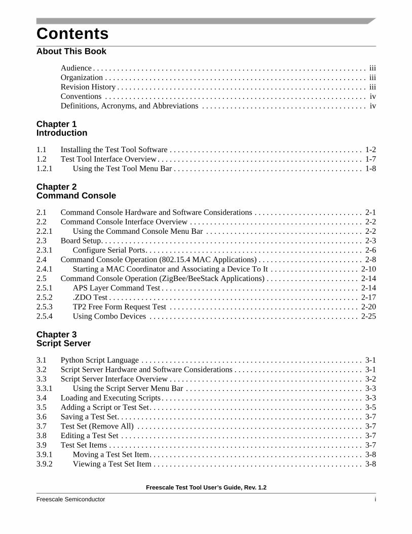
4. The Wizard searches for and installs the software for the USB Serial converter as shown in Figure 2-5 to allow the USB-connected device to operate in serial mode.
Figure 2-5. Hardware Installation Window
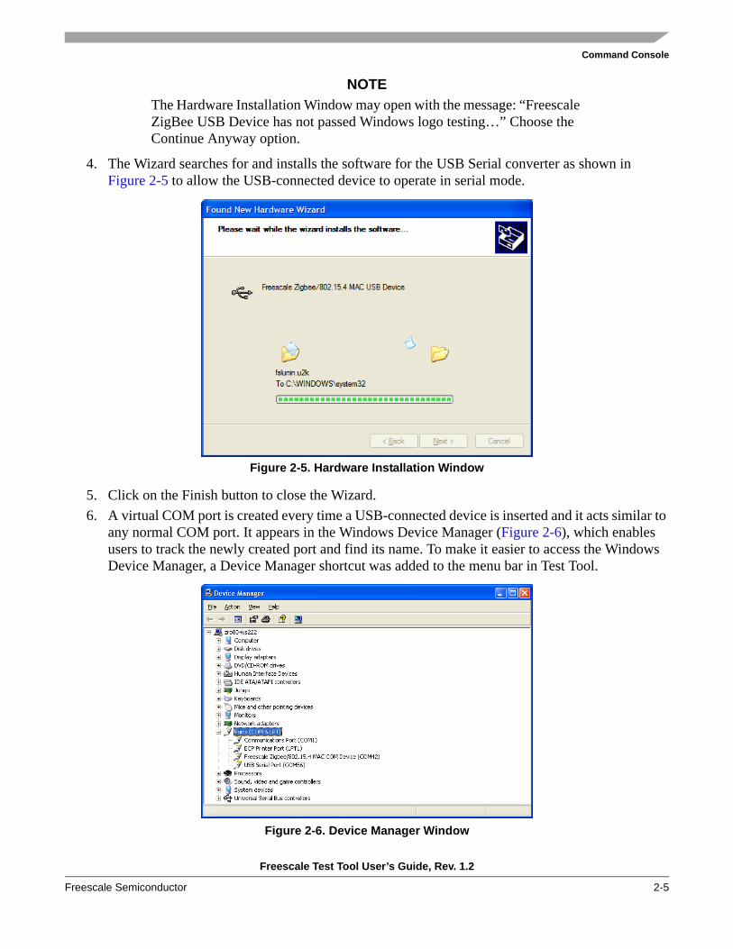
5. Click on the Finish button to close the Wizard.6. A virtual COM port is created every time a USB-connected device is inserted and it acts similar to
any normal COM port. It appears in the Windows Device Manager (Figure 2-6), which enables users to track the newly created port and find its name. To make it easier to access the Windows Device Manager, a Device Manager shortcut was added to the menu bar in Test Tool.
Figure 2-6. Device Manager Window

Command Console
Freescale Test Tool User’s Guide, Rev. 1.2
2-6 Freescale Semiconductor
NOTEBoth “Freescale Zigbee/802.15.4 MAC COM Device” and “USB Serial Port” can identify Freescale ZigBee evaluation boards in the Device Manager.
2.3.1 Configure Serial PortsEach board must now be configured using the Command Console. From the Tools option in Test Tool menu bar, select the Communications Settings option. The List of Devices window appears (Figure 2-7). If a device is not highlighted, only the following buttons are active:
• Add Internal• Add External• Close
NOTEIt is not possible to use the BDM when running the Command Console.
All other buttons are grayed out until a device already present in the list is highlighted, then the other buttons are enabled as shown in Figure 2-7.
Figure 2-7. List of Devices Window
To add the newly created devices, follow these steps:1. Click on the Add Internal button and the following window appears.

Command Console
Freescale Test Tool User’s Guide, Rev. 1.2
Freescale Semiconductor 2-7
Figure 2-8. Device Settings Window
2. Select the Serial/USB Connection radio button.3. Use the down arrow to the right of the COM port sub-menu to select the communication device. If
the menu defaults to another COM port, navigate to and select the correct COM port for each of the installed devices. If the device does not show up in the drop down list, highlight the value at the top of the drop down box and overwrite it with the correct COM port value.
4. If the board will be used for ZigBee testing, select 38400 as the baud rate. If the board will be used for IEEE 802.15.4 MAC testing, select 19200.
5. Click on the OK button.
As shown in Figure 2-8, it is also possible to select a device which is actually connected to a remote PC using TCP/IP connectivity. In this case, users should check the “WinSocket” radio button, and enter the IP address or hostname of the remote computer. The TCP/IP port number can be discovered by opening the device list window on the remote PC and observing the value corresponding to the respective device in the “location” column. Users must ensure that any firewall that may be running on the remote host allows incoming connections to the respective port.
The device may be renamed to make it easier to recall the assigned role for the device, for example, ZigBee Coordinator, by pressing the Rename button and editing the name of the device, as shown in Figure 2-7.
The Add External button allows users to add remote devices, with the added benefit of interactively searching the local network for machines having boards attached and running Test Tool. By pressing the Search button, users can browse the LAN using a tree-like widget and precisely point and click on the desired device.
To change the settings (type, port name, baud rate, location) of a device, press the Settings button. The device settings window appears and allows users to make the necessary changes. (Figure 2-8).

Command Console
Freescale Test Tool User’s Guide, Rev. 1.2
2-8 Freescale Semiconductor
2.4 Command Console Operation (802.15.4 MAC Applications)This section describes how to use the Command Console using an IEEE 802.15.4 MAC example.
Ensure that the boards are set up and cables correctly connected as shown in Section 2.3, “Board Setup”. Press the reset button of each board one time before starting the tests outlined in the following sections.
See Section 2.5, “Command Console Operation (ZigBee/BeeStack Applications)” on how to use Command Console using a ZigBee example.
To run the MAC example in Command Console perform the following steps.1. Ensure that the appropriate command set (ZigBee2006, ZigBee2007) is selected in the “Loaded
Command Set” drop down box. This example uses ZigBee2006.2. Type MAC in the Enter Command field (located at the bottom of the Command Console window).
The first field of the Status bar (the status field is below the Enter Command field) changes and displays the first available command with the prefix MAC. The Command field provides command completion so users do not have to enter the whole command name. To complete a command, press <Ctrl> + <Space>. Press <Ctrl> + <Space> again and a pop-up menu appears showing all the commands available starting with the MAC prefix.If an ambiguous command is entered, a pop-up menu appears (Figure 2-9) showing all available commands beginning with the string present in the input field.
Figure 2-9. Command Console (MAC Command Entries)
3. From the pop-up menu in the Command Console window, select MacPurge.Request.

Command Console
Freescale Test Tool User’s Guide, Rev. 1.2
Freescale Semiconductor 2-9
As shown in Figure 2-10, sub-sequent fields of the Status bar now display the parameter selected in the current command. In this case, the command is MACPurge.Request and the parameter is msduHandle with a values of 0x55. The right-most status field provides a description of the command.
Figure 2-10. Command Console (MACPurge.Reuqest Command)
4. Send the command by pressing the Enter key or clicking the Send button. The Rx/Tx view is now updated with the command that was just transmitted (MacPurge.Request). The device promptly responds with an event. The most recent item is always placed at the bottom of the list. A more detailed view of each command or event can be seen by expanding the line by clicking on the [+] symbol. In this example, the MacPurge.Request is expanded by clicking on the [+] symbol in the display area as shown in Figure 2-11.

Command Console
Freescale Test Tool User’s Guide, Rev. 1.2
2-10 Freescale Semiconductor
Figure 2-11. Command Console (Expanded Command View)
2.4.1 Starting a MAC Coordinator and Associating a Device To ItBefore working with MAC commands, ensure that the appropriate command set (ZigBee2006, ZigBee2007) is loaded. This example uses ZigBee2006. This example also requires that two boards are programmed with the ZTC application file.
A typical sequence of commands to start a Coordinator in non-beaconed mode is as follows:1. Reset the board.2. Hook the MCPS, MLME SAP using the ZTC-ModeSelect.Request command:

Command Console
Freescale Test Tool User’s Guide, Rev. 1.2
Freescale Semiconductor 2-11
Figure 2-12. Results Pane for ZTC-ModeSelect.Request
3. All boards require an extended (long) address assigned to them. Some boards may have lost their extended address or users may simply want to override the default IEEE extended address. In this case the ZTC-WriteExtAddr.Request is used to set the extended address to 0x1111111111111111.
Figure 2-13. Results Pane for ZTC-WriteExtAddr.Request
4. Use the MacSetPIBAttribute.Request to assign a short address. Then use the PIBAttribute pull-down menu and select the macShortAddress parameter to set the short address value to 0x0001.
Figure 2-14. Results Pane for MacSetPIBAttribute.Request - macShortAddress
Tx [19:59:51] ZTC-ModeSelect.Request A3 00 0A 01 01 01 00 00 00 00 00 00 00
Header [2 bytes] = A3 00UART Tx Blocking [1 byte ] = 01 (true)MCPS [1 byte ] = 01 (HookMode)MLME [1 byte ] = 01 (HookMode)ASP [1 byte ] = 00 (DisableMode)NLDE [1 byte ] = 00 (DisableMode)NLME [1 byte ] = 00 (DisableMode)APSDE [1 byte ] = 00 (DisableMode)AFDE [1 byte ] = 00 (DisableMode)APSME [1 byte ] = 00 (DisableMode)ZDP [1 byte ] = 00 (DisableMode)
Rx [19:59:51] ZTC-ModeSelect.Confirm A4 00 01 00Header [2 bytes] = A4 00PayloadLength [1 byte ] = 01 Status [1 byte ] = 00 (gSuccess)
Tx [19:59:56] ZTC-WriteExtAddr.Request A3 DB 08 11 11 11 11 11 11 11 11Header [2 bytes] = A3 DBAddress [8 bytes] = 11 11 11 11 11 11 11 11
Rx [19:59:56] ZTC-WriteExtAddr.Confirm A4 DB 01 00Header [2 bytes] = A4 DBPayloadLength [1 byte ] = 01 Status [1 byte ] = 00
Tx [20:00:10] MacSetPIBAttribute.Request 85 09 09 53 01 00 00 00 00 00 00 00
Header [2 bytes] = 85 09PIBAttribute [1 byte ] = 53 (macShortAddress)Value [8 bytes] = 00 00 00 00 00 00 00 01
Rx [20:00:10] MacSetPIBAttribute.Confirm 84 0D 06 00 53 02 00 01 00Header [2 bytes] = 84 0DPayloadLength [1 byte ] = 06 Status [1 byte ] = 00 (gSuccess_c)PIBAttribute [1 byte ] = 53 (macShortAddress

Command Console
Freescale Test Tool User’s Guide, Rev. 1.2
2-12 Freescale Semiconductor
5. Use the MacSetPIBAttribute.Request with macAssociationPermit parameter enabled. The value must be set to 0x01.
Figure 2-15. Results Pane for MacSetPIBAttribute.Request - macAssociationPermit
6. In the Command Set window, Start the Coordinator using the MacStart.Request command button.
Figure 2-16. Results Pane for MacStart.Request
7. Prepare a MacAssociate.Response message to be ready when the remote device will initiate the association.
Figure 2-17. Results Pane for MacAssociate.Response
To start an End Device, open a second Command Console by clicking View -> Command Console from the Test Tool menu bar. For ease of use, position the two Command Console windows side by side by dragging the windows in place or by clicking on Window -> Tile.
Tx [20:00:06] MacSetPIBAttribute.Request 85 09 09 41 01 00 00 00 00 00 00 00
Header [2 bytes] = 85 09PIBAttribute [1 byte ] = 41 (macAssociationPermit)Value [8 bytes] = 00 00 00 00 00 00 00 01
Rx [20:00:07] MacSetPIBAttribute.Confirm 84 0D 05 00 41 01 00 01Header [2 bytes] = 84 0DPayloadLength [1 byte ] = 05 Status [1 byte ] = 00 (gSuccess_c)PIBAttribute [1 byte ] = 41 (macAssociationPermit)
Tx [20:00:16] MacStart.Request 85 0A 09 AA 1A 13 0F 0F 01 00 00 00Header [2 bytes] = 85 0APANId [2 bytes] = 1A AA LogicalChannel [1 byte ] = 13 BeaconOrder [1 byte ] = 0F SuperframeOrder [1 byte ] = 0F PANCoordinator [1 byte ] = 01 (true)BatteryLifeExtension [1 byte ] = 00 (false)CoordRealignment [1 byte ] = 00 (false)SecurityEnable [1 byte ] = 00 (false)
Rx [20:00:16] MacStart.Confirm 84 0E 01 00Header [2 bytes] = 84 0EPayloadLength [1 byte ] = 01 Status [1 byte ] = 00 (gSuccess_c)
Tx [20:00:23] MacAssociate.Response 85 01 0C 22 22 22 22 22 22 22 22 FECA 00 00
Header [2 bytes] = 85 01DeviceAddress [8 bytes] = 22 22 22 22 22 22 22 22 AssocShortAddress [2 bytes] = CA FE SecurityEnable [1 byte ] = 00 (false)Status [1 byte ] = 00 (gSuccess_c)

Command Console
Freescale Test Tool User’s Guide, Rev. 1.2
Freescale Semiconductor 2-13
To start the End Device, perform the following steps from the second Command Console: 1. Repeat Steps 1 to 3 from the Coordinator example for the End Device replacing extended address
in Step 3 with 0x2222222222222222.2. In the Command Set window, use the MacAssociate.Request and set up the PANID with the
Coordinator’s PANID value (can get value from other device window). Also specify the Coordinator’s address and the correct address mode.
Figure 2-18. Results Pane for MacAssociate.Request
Tx [20:00:46] MacAssociate.Request 85 00 0E 11 11 11 11 11 11 11 11 AA1A 03 13 00 8E
Header [2 bytes] = 85 00CoordAddress [8 bytes] = 11 11 11 11 11 11 11 11 CoordPANId [2 bytes] = 1A AA CoordAddrMode [1 byte ] = 03 (64bitAddr)LogicalChannel [1 byte ] = 13 SecurityEnable [1 byte ] = 00 (false)CapabilityInformation [1 byte ] = 8E
Rx [20:00:46] MacAssociate.Confirm 84 01 03 FE CA 00Header [2 bytes] = 84 01PayloadLength [1 byte ] = 03 AssocShortAddress [2 bytes] = CA FE Status [1 byte ] = 00 (gSuccess_c)

Command Console
Freescale Test Tool User’s Guide, Rev. 1.2
2-14 Freescale Semiconductor
2.5 Command Console Operation (ZigBee/BeeStack Applications)This section describes how to initiate tests in Command Console for ZigBee applications. This involves use of the ZigBee Test Client (ZTC). For detailed information about the ZTC, see the Freescale ZigBee Test Client (ZTC) Reference Manual.
Ensure that the boards are set up and cables correctly connected as shown in Section 2.3, “Board Setup”. Press the reset button of each board one time before starting the tests outlined in the following sections.
At the host PC, start Test Tool, if it is not already running, and follow the steps to access the devices for testing.
From the Test Tool menu bar, follow these steps:1. Click on View -> Command Console. The Select Device window appears. 2. Highlight the first device to be monitored. In this example it is the ZigBee Coordinator. Click on
the OK button.3. Select the appropriate command set (ZigBee2006, ZigBee2007) from the Command Set window.
This example users ZigBee2007. This obtains the command and event sets from XML source files. Additionally, the Quick Access buttons now available correspond to the ZTC Mode, Addressing, and Start/Restart/Stop network request primitives.
4. Repeat Steps 1 through 3 in a new Command Console window to set up the second ZigBee device, for this test example, a ZigBee Router.
NOTESet up the environment so that it is easy to switch back and forth between the two Command Console windows. For example, click on Window -> Tile in the Test Tool menu bar.
2.5.1 APS Layer Command TestThe application support sub-layer (APS) enables direct data transmission between two devices using extended or short addresses. The APS creates the interface between the next higher layer entity and the NWK layer and allows binding of devices in the same network. The APS sub-layer services include the following:
• Direct data transmission between two devices using extended or short addresses• Indirect data transmission between two or more devices• Data transmission with end-to-end acknowledgement (APS ACK)• Data transmission using security• Setting up an authenticated relationship between two or more devices using SSP keys
The Application Support Sub-layer Management Entity (APSME) provides management services, and the Application Data Entity (APSDE) transports the APS protocol data units (APDUs) between layers.

Command Console
Freescale Test Tool User’s Guide, Rev. 1.2
Freescale Semiconductor 2-15
2.5.1.1 APS Data RequestThis APSDE-DATA.Request primitive requests the transfer of a next higher layer PDU (ASDU) from the local next higher layer entity (NHLE) to a peer NHLE entity.
This test scenario describes a simple direct APSDE data transfer from the Router to its Coordinator. Both devices must have the TestProfile2 application.
Start by resetting the devices, pressing the RESET button.
From the Command Console window of the ZigBee Coordinator:1. Click on the ZTC-ModeSelect.Request button.2. In the Parameter pane, select the MonitorMode option for APSME, APSDE and ensure the other
SAPs are set to DisableMode.3. Click on the Send button.4. Click on the ZTC-WriteExtAddr.Request button.5. In the parameters pane, type the new address: 0xaaaaaaaaaaaaaaaa.6. Click on the Send button.7. Click on the ZTC-RestartNWK.Request button.8. Click on the Send button.
Repeat the above steps for the ZigBee Router, replacing the address field in step 5 with 0x0000000100000000.
In order to send the APSDE data packet from the Router:1. Click on the All Commands button.2. Click on the APS Layer button.3. Select the APSDE-DATA.Request option.4. In the Parameters pane, select the following:
a) DstAddrMode 0x02 (16-bit address for DestAddress) b) DstAddress to 0x000000000000000 c) DstEndpoint 0xF0 d) Profileld 0x7F01 e) ClusterId 0x001C f) SrcEndpoint 0x01 g) asduLength 0x01 h) Asdu 0x00i) TxOptions 0x00 j) RadiusCounter 0x05
5. Click on the Send button.
On the Router, the following APSDE-Data messages will be displayed:

Command Console
Freescale Test Tool User’s Guide, Rev. 1.2
2-16 Freescale Semiconductor
Figure 2-19. APSDE Data Primitives on Router
On the Coordinator (receiver side) the following APSDE-Data messages will be displayed:
Figure 2-20. APSDE Data Primitive received on Coordinator
Tx [10:53:15.265] APSDE-DATA.Request 9C 00 13 02 00 00 00 00 00 00 00 00 F0 01 7F 1C 00 01 01 00 00 05
Header [2 bytes] = 9C 00DstAddrMode [1 byte ] = 02 DstAddress [8 bytes] = 00 00 00 00 00 00 00 00 DstEndpoint [1 byte ] = F0 Profileld [2 bytes] = 7F 01 ClusterId [2 bytes] = 00 1C SrcEndpoint [1 byte ] = 01 asduLength [1 byte ] = 01 Asdu [1 byte ] = 00
Asdu[0] = 00TxOptions [1 byte ] = 00 RadiusCounter [1 byte ] = 05
Rx [10:53:15.312] APSDE-DATA.Confirm 9D 00 11 02 00 00 00 00 00 00 00 00 F0 01 00 00 00 00 00 CCHeader [2 bytes] = 9D 00PayloadLength [1 byte ] = 11 DstAddrMode [1 byte ] = 02 DstAddress [8 bytes] = 00 00 00 00 00 00 00 00 DstEndpoint [1 byte ] = F0 SrcEndpoint [1 byte ] = 01 Status [1 byte ] = 00 (gSuccess)TxTime [4 bytes] = 00 00 00 00 ConfirmID [1 byte ] = CC
Rx [10:53:15.312] APSDE-DATA.Indication 9D 01 1D 02 00 00 F0 02 CB EB 01 01 7F 1C 00 01 00 00 00 AF BF 00 00 00 00 00 00 00 00 00 00 00
Header [2 bytes] = 9D 01PayloadLength [1 byte ] = 1D DestAddrMode [1 byte ] = 02 (16bit Addr and DstEndpoint)DstAddress [2 bytes] = 00 00 DstEndpoint [1 byte ] = F0 SrcAddrMode [1 byte ] = 02 SrcAddress [2 bytes] = EB CB SrcEndpoint [1 byte ] = 01 ProfileId [2 bytes] = 7F 01 ClusterId [2 bytes] = 00 1C asduLength [1 byte ] = 01 asdu [1 byte ] = 00
asdu[0] = 00Status [1 byte ] = 00 (Success)WasBroadcast [1 byte ] = 00 (FALSE)SecurityStatus [1 byte ] = AF (gUnsecured)LinkQuality [1 byte ] = BF RxTime [4 bytes] = 00 00 00 00 iMsgType [1 byte ] = 00 pNext [2 bytes] = 00 00 iDataSize [1 byte ] = 00 pData [2 bytes] = 00 00 iBufferNumber [1 byte ] = 00
Command Console
Freescale Test Tool User’s Guide, Rev. 1.2
Freescale Semiconductor 2-17
2.5.2 .ZDO TestZigBee Device Objects (ZDO) manages device and service discovery, and it serves as security manager, network manager, binding manager, and node manager. In general, ZigBee Device Objects function to:
• Initialize the NWK, APS, and SSP layers• Start the network • Provide applications with services to get information about routing, binding, addresses, device
capabilities, and endpoints
2.5.2.1 ZDP IEEE Address RequestThis test verifies that the Device Under Test (DUT) in the role of a ZigBee Coordinator is capable of operating a ZigBee Device Profile (ZDP).
The test ensures that the Router, can send a ZDP-IEEE-Adreess.Request to the Coordinator and receive a response.
1. Start by resetting the devices, pressing the RESET button.2. From the Command Console window of the ZigBee Coordinator:
a) Click on the ZTC-ModeSelect.Request button.b) In the Parameter pane, select the MonitorMode option for APSME, APSDE, ZDP and ensure
the other SAPs are set to DisableMode.c) Click on the Send button.d) Click on the ZTC-WriteExtAddr.Request button.e) In the parameters pane, type the new address: 0xaaaaaaaaaaaaaaaa.f) Click on the Send button.g) Click on the ZTC-RestartNWK.Request button.h) Click on the Send button.
Repeat the above steps for the ZigBee Router, replacing the address field in step 5 with 0x0000000100000000.
From the Command Console of the Router, initiate the ZDP IEEE address request test using these steps:1. Click on the All Commands button.2. Click on the ZDO layer commands button. 3. Select the ZDP-IEEE_addr_req.Request option. 4. In the Parameters pane do the following:
a) Select as the DestAddress 0x0000, coordinator address.b) Select as the NWKAddress 0x0000, coordinator addressc) RequestType 0x01, corresponding to extended response.d) StartIndex 0x00.
5. Click on the Send button.

Command Console
Freescale Test Tool User’s Guide, Rev. 1.2
2-18 Freescale Semiconductor
The results pane for the Router, as shown in Figure 2-21, displays the transmitted ZDP-IEEE_addr_req.Request primitive, followed by the APSDE-DATA.Request, and ASPDE-DATA.Confirm primitives.
Figure 2-21. Router sending ZDP IEEE Address Request
Tx [15:59:17.062] ZDP-IEEE_addr_req.Request A2 01 06 00 00 00 00 01 00Header [2 bytes] = A2 01DestAddress [2 bytes] = 00 00 NWKAddress [2 bytes] = 00 00 RequestType [1 byte ] = 01 StartIndex [1 byte ] = 00
Rx [15:59:17.203] APSDE-DATA.Request 9C 00 1B 02 00 00 00 00 00 00 00 00 00 00 00 01 00 00 05 05 00 00 01 00 00 0A 00 00 00 00
Header [2 bytes] = 9C 00PayloadLength [1 byte ] = 1B DstAddrMode [1 byte ] = 02 DstAddress [8 bytes] = 00 00 00 00 00 00 00 00 DstEndpoint [1 byte ] = 00 Profileld [2 bytes] = 00 00 ClusterId [2 bytes] = 00 01 SrcEndpoint [1 byte ] = 00 asduLength [1 byte ] = 05 Asdu [5 bytes] = 05 00 00 01 00
Asdu[0] = 05Asdu[1] = 00Asdu[2] = 00Asdu[3] = 01Asdu[4] = 00
TxOptions [1 byte ] = 00 RadiusCounter [1 byte ] = 0A iMsgType [1 byte ] = 00 pNextDataBlock [2 bytes] = 00 00 iDataSize [1 byte ] = 00
Rx [15:59:17.218] APSDE-DATA.Confirm 9D 00 11 02 00 00 00 00 00 00 00 00 00 00 00 00 00 00 00 96Header [2 bytes] = 9D 00PayloadLength [1 byte ] = 11 DstAddrMode [1 byte ] = 02 DstAddress [8 bytes] = 00 00 00 00 00 00 00 00 DstEndpoint [1 byte ] = 00 SrcEndpoint [1 byte ] = 00 Status [1 byte ] = 00 (gSuccess)TxTime [4 bytes] = 00 00 00 00 ConfirmID [1 byte ] = 96

Command Console
Freescale Test Tool User’s Guide, Rev. 1.2
Freescale Semiconductor 2-19
The results pane for the Router, as shown in Figure 2-22, displays the APSDE-DATA.Indication followed by ZDP-IEEE_addr.response primitive.
Figure 2-22. Router receiving the ZDP IEEE Address Response from Coordinator
Rx [15:59:17.234] APSDE-DATA.Indication 9D 01 2C 02 9B D7 00 02 00 00 00 00 00 01 80 10 05 00 AA AA AA AA AA AA AA AA 00 00 01 00 9B D7 00 00 AF B3 00 00 00 00 00 00 00 00 00 00 00
Header [2 bytes] = 9D 01PayloadLength [1 byte ] = 2C DestAddrMode [1 byte ] = 02 (16bit Addr and DstEndpoint)DstAddress [2 bytes] = D7 9B DstEndpoint [1 byte ] = 00 SrcAddrMode [1 byte ] = 02 SrcAddress [2 bytes] = 00 00 SrcEndpoint [1 byte ] = 00 ProfileId [2 bytes] = 00 00 ClusterId [2 bytes] = 80 01 asduLength [1 byte ] = 10 asdu [16 bytes] = 05 00 AA AA AA AA AA AA AA AA 00 00 01 00 9B D7
asdu[0] = 05asdu[1] = 00asdu[2] = AAasdu[3] = AAasdu[4] = AAasdu[5] = AAasdu[6] = AAasdu[7] = AAasdu[8] = AAasdu[9] = AAasdu[10] = 00asdu[11] = 00asdu[12] = 01asdu[13] = 00asdu[14] = 9Basdu[15] = D7
Status [1 byte ] = 00 (Success)WasBroadcast [1 byte ] = 00 (FALSE)SecurityStatus [1 byte ] = AF (gUnsecured)LinkQuality [1 byte ] = B3 RxTime [4 bytes] = 00 00 00 00 iMsgType [1 byte ] = 00 pNext [2 bytes] = 00 00 iDataSize [1 byte ] = 00 pData [2 bytes] = 00 00 iBufferNumber [1 byte ] = 00
Rx [15:59:17.250] ZDP-IEEE_addr.response A0 81 0F 00 AA AA AA AA AA AA AA AA 00 00 01 00 9B D7Header [2 bytes] = A0 81PayloadLength [1 byte ] = 0F Status [1 byte ] = 00 (Success)IEEEAddrRemoteDev [8 bytes] = AA AA AA AA AA AA AA AA NWKAddrRemoteDev [2 bytes] = 00 00 NumOfAssociatedDevice [1 byte ] = 01 StartIndex [1 byte ] = 00 ListOfShortAddress [2 bytes] = 9B D7
ListOfShortAddress[0] = D7 9B

Command Console
Freescale Test Tool User’s Guide, Rev. 1.2
2-20 Freescale Semiconductor
2.5.3 TP2 Free Form Request TestThis test verifies that the DUT in the role of a ZigBee Coordinator is capable of operating a profile on an endpoint (in this example TestProfile2 endpoints are used).
The test ensures that an endpoint on a ZigBee device, in this example the Router, can send a FreeForm.Request to another endpoint (to Coordinator) with an 8-bit integer, and receive a response.
The request type field specifies the FreeForm.Request type based on its value. As shown in Table 2-1, the field can take any one of the non-reserved values listed.
Start by resetting the devices, pressing the RESET button.
From the Command Console window of the ZigBee Coordinator:1. Click on the ZTC-ModeSelect.Request button.2. In the Parameter pane, select the MonitorMode option for APSME, APSDE, AFDE, ZDP and
ensure the other SAPs are set to DisableMode.3. Click on the Send button.4. Click on the ZTC-WriteExtAddr.Request button.5. In the parameters pane, type the new address: 0xaaaaaaaaaaaaaaaa.6. Click on the Send button.7. Click on the ZTC-RestartNWK.Request button.8. Click on the Send button.
Repeat the above steps for the ZigBee Router, replacing the address field in step 5 with 0x0000000100000000.
Table 2-1. Values of Request Type Field
Request Type Field Value Request Description
0x00 Request 8-bit integer value
0x01 Request character string
0x02 Request coordinates
0x03 Request 16-bit integer value
0x04 Request no data value
0x05 Request relative time value
0x06 Request absolute time value
0x07 - 0xff Reserved

Command Console
Freescale Test Tool User’s Guide, Rev. 1.2
Freescale Semiconductor 2-21
From the Command Console of the Router, initiate the Free Form test with these steps:1. Click on the All Commands button.2. Click on the Test Profile 2 button. 3. Select the FreeForm.Request option.4. In the Parameters pane, do the following:
a) Select as the Network Address 0x0000.b) Select as the Request Type 0x00 (the 8-bit integer).
5. Click on the Send button.
The results pane for the Router, as shown in Figure 2-23, displays the transmitted FreeForm.Request primitive, followed by the APSDE-DATA.Request, FreeForm.Confirm, and ASPDE-DATA.Confirm primitives.
Figure 2-23. Primitives Transmitted and Received by the Router
Tx [10:55:32.500] FreeformReq 69 0A 03 00 00 00Header [2 bytes] = 69 0aNetwork_Address [2 bytes] = 00 00 RequestType [1 byte ] = 00
Rx [10:55:32.625] APSDE-DATA.Request 9C 00 17 02 00 00 A1 A1 A1 A1 A1 A1 F0 01 7F A8 A0 01 01 00 00 0A 00 00 00 00
Header [2 bytes] = 9C 00PayloadLength [1 byte ] = 17 DstAddrMode [1 byte ] = 02 DstAddress [8 bytes] = A1 A1 A1 A1 A1 A1 00 00 DstEndpoint [1 byte ] = F0 Profileld [2 bytes] = 7F 01 ClusterId [2 bytes] = A0 A8 SrcEndpoint [1 byte ] = 01 asduLength [1 byte ] = 01 Asdu [1 byte ] = 00
Asdu[0] = 00TxOptions [1 byte ] = 00 RadiusCounter [1 byte ] = 0A iMsgType [1 byte ] = 00 pNextDataBlock [2 bytes] = 00 00 iDataSize [1 byte ] = 00
Rx [10:55:32.640] Freeform.confirm 69 0A 01 00Header [2 bytes] = 69 0aPayloadLength [1 byte ] = 01
Rx [10:55:32.640] APSDE-DATA.Confirm 9D 00 11 02 00 00 A1 A1 A1 A1 A1 A1 F0 01 00 00 00 00 00 CDHeader [2 bytes] = 9D 00PayloadLength [1 byte ] = 11 DstAddrMode [1 byte ] = 02 DstAddress [8 bytes] = A1 A1 A1 A1 A1 A1 00 00 DstEndpoint [1 byte ] = F0 SrcEndpoint [1 byte ] = 01 Status [1 byte ] = 00 (gSuccess)TxTime [4 bytes] = 00 00 00 00 ConfirmID [1 byte ] = CD
Command Console
Freescale Test Tool User’s Guide, Rev. 1.2
2-22 Freescale Semiconductor
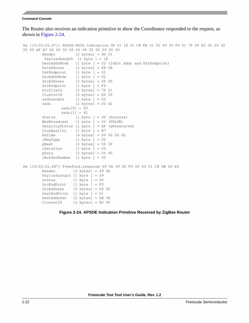
The Router also receives an indication primitive to show the Coordinator responded to the request, as shown in Figure 2-24.
Figure 2-24. APSDE Indication Primitive Received by ZigBee Router
Rx [10:55:32.671] APSDE-DATA.Indication 9D 01 1E 02 CB EB 01 02 00 00 F0 01 7F 00 E0 02 00 42 00 00 AF B7 00 00 00 00 00 00 00 00 00 00 00
Header [2 bytes] = 9D 01 PayloadLength [1 byte ] = 1E DestAddrMode [1 byte ] = 02 (16bit Addr and DstEndpoint)DstAddress [2 bytes] = EB CB DstEndpoint [1 byte ] = 01 SrcAddrMode [1 byte ] = 02 SrcAddress [2 bytes] = 00 00 SrcEndpoint [1 byte ] = F0 ProfileId [2 bytes] = 7F 01 ClusterId [2 bytes] = E0 00 asduLength [1 byte ] = 02 asdu [2 bytes] = 00 42
asdu[0] = 00asdu[1] = 42
Status [1 byte ] = 00 (Success)WasBroadcast [1 byte ] = 00 (FALSE)SecurityStatus [1 byte ] = AF (gUnsecured)LinkQuality [1 byte ] = B7 RxTime [4 bytes] = 00 00 00 00 iMsgType [1 byte ] = 00 pNext [2 bytes] = 00 00 iDataSize [1 byte ] = 00 pData [2 bytes] = 00 00 iBufferNumber [1 byte ] = 00
Rx [10:55:32.687] Freeform.response 69 0B 09 00 F0 00 00 01 CB EB 00 E0Header [2 bytes] = 69 0bPayloadLength [1 byte ] = 09 status [1 byte ] = 00 SrcEndPoint [1 byte ] = F0 SrcAddress [2 bytes] = 00 00 DestEndPoint [1 byte ] = 01 DestAddress [2 bytes] = EB CB ClusterID [2 bytes] = E0 00

Command Console
Freescale Test Tool User’s Guide, Rev. 1.2
Freescale Semiconductor 2-23
The results pane for the Coordinator displays the indication primitive, as shown in Figure 2-25, including the APSDE indication primitives captured using MonitorMode.
Figure 2-25. Free Form Results for ZigBee Coordinator
Rx [10:55:32.640] APSDE-DATA.Indication 9D 01 1D 02 00 00 F0 02 CB EB 01 01 7F A8 A0 01 00 00 00 AF BF 00 00 00 00 00 00 00 00 00 00 00
Header [2 bytes] = 9D 01PayloadLength [1 byte ] = 1D DestAddrMode [1 byte ] = 02 (16bit Addr and DstEndpoint)DstAddress [2 bytes] = 00 00 DstEndpoint [1 byte ] = F0 SrcAddrMode [1 byte ] = 02 SrcAddress [2 bytes] = EB CB SrcEndpoint [1 byte ] = 01 ProfileId [2 bytes] = 7F 01 ClusterId [2 bytes] = A0 A8 asduLength [1 byte ] = 01 asdu [1 byte ] = 00
asdu[0] = 00Status [1 byte ] = 00 (Success)WasBroadcast [1 byte ] = 00 (FALSE)SecurityStatus [1 byte ] = AF (gUnsecured)LinkQuality [1 byte ] = BF RxTime [4 bytes] = 00 00 00 00 iMsgType [1 byte ] = 00 pNext [2 bytes] = 00 00 iDataSize [1 byte ] = 00 pData [2 bytes] = 00 00 iBufferNumber [1 byte ] = 00

Command Console
Freescale Test Tool User’s Guide, Rev. 1.2
2-24 Freescale Semiconductor
The Coordinator additionally issues a response to request from the Router, shown in Figure 2-26, with the APSDE-DATA.Request primitive.
Figure 2-26. Request and Confirm Primitives for Coordinator
Rx [10:55:32.671] APSDE-DATA.Request 9C 00 18 02 CB EB A1 A1 A1 A1 A1 A1 01 01 7F 00 E0 F0 02 00 42 00 0A 00 00 00 00
Header [2 bytes] = 9C 00PayloadLength [1 byte ] = 18 DstAddrMode [1 byte ] = 02 DstAddress [8 bytes] = A1 A1 A1 A1 A1 A1 EB CB DstEndpoint [1 byte ] = 01 Profileld [2 bytes] = 7F 01 ClusterId [2 bytes] = E0 00 SrcEndpoint [1 byte ] = F0 asduLength [1 byte ] = 02 Asdu [2 bytes] = 00 42
Asdu[0] = 00Asdu[1] = 42
TxOptions [1 byte ] = 00 RadiusCounter [1 byte ] = 0A iMsgType [1 byte ] = 00 pNextDataBlock [2 bytes] = 00 00 iDataSize [1 byte ] = 00
Rx [10:55:32.687] Freeform.confirm 69 0A 09 00 01 CB EB F0 00 00 A8 A0Header [2 bytes] = 69 0aPayloadLength [1 byte ] = 09
Rx [10:55:32.687] APSDE-DATA.Confirm 9D 00 11 02 CB EB A1 A1 A1 A1 A1 A1 01 F0 00 00 00 00 00 98
Header [2 bytes] = 9D 00PayloadLength [1 byte ] = 11 DstAddrMode [1 byte ] = 02 DstAddress [8 bytes] = A1 A1 A1 A1 A1 A1 EB CB DstEndpoint [1 byte ] = 01 SrcEndpoint [1 byte ] = F0 Status [1 byte ] = 00 (gSuccess)TxTime [4 bytes] = 00 00 00 00 ConfirmID [1 byte ] = 98

Command Console
Freescale Test Tool User’s Guide, Rev. 1.2
Freescale Semiconductor 2-25
2.5.4 Using Combo DevicesTo start a network using the ComboDevice as the target, use the ZTC-StartNwkEx.Request. This command has the following parameters:
• DeviceType — specifies what type of device it is.— 0xC0: Start as coordinator(ZC);— 0x80: Start as router(ZR);— 0x20: Start as end device with RxOnWhenIdle = False(ZED);— 0x60: Start as end device with RxOnWhenIdle = True(ZED).
• StartupSet — specifies what working set will be used.— 0x00: Copy NVM set (if any) to working set, then start. If no NVM, use ROM set.— 0x08: Copy ROM set to working set (factory defaults), then start.— 0x10: Use working startup set in RAM.— 0x18: Copy commissioning cluster set to working set, then start. If not valid, use NVM set.
• StartupControlMode — specifies which way to start the device.— 0x00: Use association (ZR, ZED only), or form (ZC).— 0x01: FS specific: use orphan rejoin (ZR, ZED only).— 0x02: Use NWK rejoin (ZR, ZED only).— 0x03: Valid for ZR, ZED only, search for network on this and other channels, then silent join.— 0x04: Already part of the network (no form/join needed).
2.5.4.1 Forming a ZR, ZC and ZED Network using Combo DevicesPerform the following tasks to form a simple network using a ZR->ZC<-ZED, using ComboDevices.
• Reset the boards by pressing the Reset button on each board.• From the Command Console window of the device acting as the ZigBee Coordinator, perform the
following tasks:1. Click on the ZTC-ModeSelect.Request button.2. In the Parameter pane, select the MonitorMode option for ZDP and ensure the other SAPs are set
to DisableMode.3. Click on the Send button.4. Click on the ZTC-WriteExtAddr.Request button.5. In the parameters pane, type the new address: 0xaaaaaaaaaaaaaaaa.6. Click on the Send button.7. Click on the All Commands button.8. Click on the ZTC layer commands button.9. Select the ZTC-StartNwkEx.Request option. 10. In the Parameters pane do the following:
a) Select Device Type: Device as ZC.

Command Console
Freescale Test Tool User’s Guide, Rev. 1.2
2-26 Freescale Semiconductor
b) Select Startup Set: Use working set.c) Select Startup Control Mode: Association
11. Click on the Send button.
Repeat these steps for the ZigBee Router. Use extended address 0xbbbbbbbbbbbbbb in Step 5, and replace Device Type with Device as ZR in Step 10-a.
Repeat these steps for the ZigBee End Device. Use extended address 0xccccccccccccccc in Step 5 and replacing Device Type with Device as Device as ZED in step 10-a.
2.5.4.2 ZR -> ZC <- ZED Network CommandsThis section describes the Test Tool commands to create a simple network using a ZR->ZC<-ZED. This network sends data from the ZC to the ZR and ZED.
Command Console Log for ZC
Tx [10:58:46.375] ZTC-ModeSelect.Request A3 00 0A 01 00 00 00 00 00 02 00 02 02Header [2 bytes] = A3 00UART Tx Blocking [1 byte ] = 01 (true)MCPS [1 byte ] = 00 (DisableMode)MLME [1 byte ] = 00 (DisableMode)ASP [1 byte ] = 00 (DisableMode)NLDE [1 byte ] = 00 (DisableMode)NLME [1 byte ] = 00 (DisableMode)APSDE [1 byte ] = 02 (MonitorMode)AFDE [1 byte ] = 00 (DisableMode)APSME [1 byte ] = 02 (MonitorMode)ZDP [1 byte ] = 02 (MonitorMode)
Rx [10:58:46.406] SerialPortNoise 51 05 01 FFHeader [2 bytes] = 51 05PayloadLength [1 byte ] = 01 Payload [1 byte ] = FF
Rx [10:58:46.484] ZTC-ModeSelect.Confirm A4 00 01 00Header [2 bytes] = A4 00PayloadLength [1 byte ] = 01 Status [1 byte ] = 00 (gSuccess)
Tx [10:58:48.687] ZTC-WriteExtAddr.Request A3 DB 08 AA AA AA AA AA AA AA AAHeader [2 bytes] = A3 DBAddress [8 bytes] = AA AA AA AA AA AA AA AA
Rx [10:58:48.796] ZTC-WriteExtAddr.Confirm A4 DB 01 00Header [2 bytes] = A4 DBPayloadLength [1 byte ] = 01 Status [1 byte ] = 00
Tx [10:59:05.859] ZTC-StartNwkEx.Request A3 E7 03 C0 10 00Header [2 bytes] = A3 E7Device Type [1 byte ] = C0 (Device as ZC)Startup set [1 byte ] = 10 (Use working set)Startup control mode [1 byte ] = 00 (Association)

Command Console
Freescale Test Tool User’s Guide, Rev. 1.2
Freescale Semiconductor 2-27
Rx [10:59:05.968] ZTC-StartNwkEx.Confirm A4 E7 01 00Header [2 bytes] = A4 E7PayloadLength [1 byte ] = 01 Status [1 byte ] = 00 (gZbSuccess_c)
Rx [10:59:05.984] ZDO_EventOccurred.Indication A0 E6 01 00Header [2 bytes] = A0 e6PayloadLength [1 byte ] = 01 EventStatus [1 byte ] = 00 (Device Initialized)
Rx [10:59:06.000] ZDO_EventOccurred.Indication A0 E6 01 01Header [2 bytes] = A0 e6PayloadLength [1 byte ] = 01 EventStatus [1 byte ] = 01 (Device in Network Discovery State)
Rx [10:59:06.640] ZDO_EventOccurred.Indication A0 E6 01 03Header [2 bytes] = A0 e6PayloadLength [1 byte ] = 01 EventStatus [1 byte ] = 03 (Device in Coordinator starting state)
Rx [10:59:06.750] ZDO_EventOccurred.Indication A0 E6 01 10Header [2 bytes] = A0 e6PayloadLength [1 byte ] = 01 EventStatus [1 byte ] = 10 (Device in Coordinator Running state)
Rx [10:59:36.390] APSDE-DATA.Indication 9D 01 2C 02 00 00 00 02 87 C8 00 00 00 13 00 0C 02 87 C8 BB BB BB BB BB BB BB BB 8E 00 01 00 C0 00 00 00 00 00 00 00 00 00 00 00 00 00 00 00
Header [2 bytes] = 9D 01PayloadLength [1 byte ] = 2C DestAddrMode [1 byte ] = 02 (16bit Addr and DstEndpoint)DstAddress [2 bytes] = 00 00 DstEndpoint [1 byte ] = 00 SrcAddrMode [1 byte ] = 02 SrcAddress [2 bytes] = C8 87 SrcEndpoint [1 byte ] = 00 ProfileId [2 bytes] = 00 00 ClusterId [2 bytes] = 00 13 asduLength [1 byte ] = 0C asdu [12 bytes] = 02 87 C8 BB BB BB BB BB BB BB BB 8E
asdu[0] = 02asdu[1] = 87asdu[2] = C8asdu[3] = BBasdu[4] = BBasdu[5] = BBasdu[6] = BBasdu[7] = BBasdu[8] = BBasdu[9] = BBasdu[10] = BBasdu[11] = 8E
Status [1 byte ] = 00 (Success)WasBroadcast [1 byte ] = 01 (TRUE)SecurityStatus [1 byte ] = 00 (gUnsecured)LinkQuality [1 byte ] = C0 RxTime [4 bytes] = 00 00 00 00

Command Console
Freescale Test Tool User’s Guide, Rev. 1.2
2-28 Freescale Semiconductor
iMsgType [1 byte ] = 00 pNext [2 bytes] = 00 00 iDataSize [1 byte ] = 00 pData [2 bytes] = 00 00 iBufferNumber [1 byte ] = 00
Rx [11:00:01.312] APSDE-DATA.Indication 9D 01 2C 02 00 00 00 02 15 A6 00 00 00 13 00 0C 02 15 A6 CC CC CC CC CC CC CC CC 84 00 01 00 90 00 00 00 00 00 00 00 00 00 00 00 00 00 00 00
Header [2 bytes] = 9D 01PayloadLength [1 byte ] = 2C DestAddrMode [1 byte ] = 02 (16bit Addr and DstEndpoint)DstAddress [2 bytes] = 00 00 DstEndpoint [1 byte ] = 00 SrcAddrMode [1 byte ] = 02 SrcAddress [2 bytes] = A6 15 SrcEndpoint [1 byte ] = 00 ProfileId [2 bytes] = 00 00 ClusterId [2 bytes] = 00 13 asduLength [1 byte ] = 0C asdu [12 bytes] = 02 15 A6 CC CC CC CC CC CC CC CC 84
asdu[0] = 02asdu[1] = 15asdu[2] = A6asdu[3] = CCasdu[4] = CCasdu[5] = CCasdu[6] = CCasdu[7] = CCasdu[8] = CCasdu[9] = CCasdu[10] = CCasdu[11] = 84
Status [1 byte ] = 00 (Success)WasBroadcast [1 byte ] = 01 (TRUE)SecurityStatus [1 byte ] = 00 (gUnsecured)LinkQuality [1 byte ] = 90 RxTime [4 bytes] = 00 00 00 00 iMsgType [1 byte ] = 00 pNext [2 bytes] = 00 00 iDataSize [1 byte ] = 00 pData [2 bytes] = 00 00 iBufferNumber [1 byte ] = 00
Tx [11:00:34.062] APSDE-DATA.Request 9C 00 13 03 BB BB BB BB BB BB BB BB F0 01 7F 00 01 01 01 01 00 05
Header [2 bytes] = 9C 00DstAddrMode [1 byte ] = 03 DstAddress [8 bytes] = BB BB BB BB BB BB BB BB DstEndpoint [1 byte ] = F0 Profileld [2 bytes] = 7F 01 ClusterId [2 bytes] = 01 00 SrcEndpoint [1 byte ] = 01 asduLength [1 byte ] = 01 Asdu [1 byte ] = 01
Asdu[0] = 01TxOptions [1 byte ] = 00 RadiusCounter [1 byte ] = 05

Command Console
Freescale Test Tool User’s Guide, Rev. 1.2
Freescale Semiconductor 2-29
Rx [11:00:34.109] APSDE-DATA.Confirm 9D 00 11 03 BB BB BB BB BB BB BB BB F0 01 00 00 00 00 00 00Header [2 bytes] = 9D 00PayloadLength [1 byte ] = 11 DstAddrMode [1 byte ] = 03 DstAddress [8 bytes] = BB BB BB BB BB BB BB BB DstEndpoint [1 byte ] = F0 SrcEndpoint [1 byte ] = 01 Status [1 byte ] = 00 (gSuccess)TxTime [4 bytes] = 00 00 00 00 ConfirmID [1 byte ] = 00
Tx [11:01:16.500] APSDE-DATA.Request 9C 00 13 03 CC CC CC CC CC CC CC CC F0 01 7F 00 01 01 01 01 00 05
Header [2 bytes] = 9C 00DstAddrMode [1 byte ] = 03 DstAddress [8 bytes] = CC CC CC CC CC CC CC CC DstEndpoint [1 byte ] = F0 Profileld [2 bytes] = 7F 01 ClusterId [2 bytes] = 01 00 SrcEndpoint [1 byte ] = 01 asduLength [1 byte ] = 01 Asdu [1 byte ] = 01
Asdu[0] = 01TxOptions [1 byte ] = 00 RadiusCounter [1 byte ] = 05
Rx [11:01:19.312] APSDE-DATA.Confirm 9D 00 11 03 CC CC CC CC CC CC CC CC F0 01 00 00 00 00 00 01Header [2 bytes] = 9D 00PayloadLength [1 byte ] = 11 DstAddrMode [1 byte ] = 03 DstAddress [8 bytes] = CC CC CC CC CC CC CC CC DstEndpoint [1 byte ] = F0 SrcEndpoint [1 byte ] = 01 Status [1 byte ] = 00 (gSuccess)TxTime [4 bytes] = 00 00 00 00 ConfirmID [1 byte ] = 01

Command Console
Freescale Test Tool User’s Guide, Rev. 1.2
2-30 Freescale Semiconductor
Command Console Log for ZR
Tx [10:59:25.328] ZTC-ModeSelect.Request A3 00 0A 01 00 00 00 00 00 02 00 02 02Header [2 bytes] = A3 00UART Tx Blocking [1 byte ] = 01 (true)MCPS [1 byte ] = 00 (DisableMode)MLME [1 byte ] = 00 (DisableMode)ASP [1 byte ] = 00 (DisableMode)NLDE [1 byte ] = 00 (DisableMode)NLME [1 byte ] = 00 (DisableMode)APSDE [1 byte ] = 02 (MonitorMode)AFDE [1 byte ] = 00 (DisableMode)APSME [1 byte ] = 02 (MonitorMode)ZDP [1 byte ] = 02 (MonitorMode)
Rx [10:59:25.359] SerialPortNoise 51 05 01 FFHeader [2 bytes] = 51 05PayloadLength [1 byte ] = 01 Payload [1 byte ] = FF
Rx [10:59:25.359] ZTC-ModeSelect.Confirm A4 00 01 00Header [2 bytes] = A4 00PayloadLength [1 byte ] = 01 Status [1 byte ] = 00 (gSuccess)
Tx [10:59:27.015] ZTC-WriteExtAddr.Request A3 DB 08 BB BB BB BB BB BB BB BBHeader [2 bytes] = A3 DBAddress [8 bytes] = BB BB BB BB BB BB BB BB
Rx [10:59:27.125] ZTC-WriteExtAddr.Confirm A4 DB 01 00Header [2 bytes] = A4 DBPayloadLength [1 byte ] = 01 Status [1 byte ] = 00
Tx [10:59:35.093] ZTC-StartNwkEx.Request A3 E7 03 80 10 00Header [2 bytes] = A3 E7Device Type [1 byte ] = 80 (Device as ZR)Startup set [1 byte ] = 10 (Use working set)Startup control mode [1 byte ] = 00 (Association)
Rx [10:59:35.203] ZTC-StartNwkEx.Confirm A4 E7 01 00Header [2 bytes] = A4 E7PayloadLength [1 byte ] = 01 Status [1 byte ] = 00 (gZbSuccess_c)
Rx [10:59:35.203] ZDO_EventOccurred.Indication A0 E6 01 00Header [2 bytes] = A0 e6PayloadLength [1 byte ] = 01 EventStatus [1 byte ] = 00 (Device Initialized)
Rx [10:59:35.218] ZDO_EventOccurred.Indication A0 E6 01 01Header [2 bytes] = A0 e6PayloadLength [1 byte ] = 01 EventStatus [1 byte ] = 01 (Device in Network Discovery State)
Rx [10:59:35.750] ZDO_EventOccurred.Indication A0 E6 01 02Header [2 bytes] = A0 e6
Command Console
Freescale Test Tool User’s Guide, Rev. 1.2
Freescale Semiconductor 2-31
PayloadLength [1 byte ] = 01 EventStatus [1 byte ] = 02 (Device Join Network state)
Rx [10:59:36.250] ZDO_EventOccurred.Indication A0 E6 01 04Header [2 bytes] = A0 e6PayloadLength [1 byte ] = 01 EventStatus [1 byte ] = 04 (Device in Router Running state)
Rx [10:59:36.265] ZDP-EndDeviceAnnounce.Request A2 13 0D FD FF 87 C8 BB BB BB BB BB BB BB BB 8EHeader [2 bytes] = A2 13PayloadLength [1 byte ] = 0D DestinationAddress [2 bytes] = FF FD NwkAddress [2 bytes] = C8 87 IEEEAddress [8 bytes] = BB BB BB BB BB BB BB BB Capability [1 byte ] = 8E
Rx [10:59:36.359] APSDE-DATA.Request 9C 00 25 02 FD FF 00 00 00 00 00 00 00 00 00 13 00 00 0C 02 87 C8 BB BB BB BB BB BB BB BB 8E 00 1E 00 00 00 00 00 00 00
Header [2 bytes] = 9C 00PayloadLength [1 byte ] = 25 DstAddrMode [1 byte ] = 02 DstAddress [8 bytes] = 00 00 00 00 00 00 FF FD DstEndpoint [1 byte ] = 00 Profileld [2 bytes] = 00 00 ClusterId [2 bytes] = 00 13 SrcEndpoint [1 byte ] = 00 asduLength [1 byte ] = 0C Asdu [12 bytes] = 02 87 C8 BB BB BB BB BB BB BB BB 8E
Asdu[0] = 02Asdu[1] = 87Asdu[2] = C8Asdu[3] = BBAsdu[4] = BBAsdu[5] = BBAsdu[6] = BBAsdu[7] = BBAsdu[8] = BBAsdu[9] = BBAsdu[10] = BBAsdu[11] = 8E
TxOptions [1 byte ] = 00 RadiusCounter [1 byte ] = 1E iMsgType [1 byte ] = 00 pNextDataBlock [2 bytes] = 00 00 iDataSize [1 byte ] = 00
Rx [10:59:36.375] APSDE-DATA.Confirm 9D 00 11 02 FD FF 00 00 00 00 00 00 00 00 00 00 00 00 00 00Header [2 bytes] = 9D 00PayloadLength [1 byte ] = 11 DstAddrMode [1 byte ] = 02 DstAddress [8 bytes] = 00 00 00 00 00 00 FF FD DstEndpoint [1 byte ] = 00 SrcEndpoint [1 byte ] = 00 Status [1 byte ] = 00 (gSuccess)TxTime [4 bytes] = 00 00 00 00 ConfirmID [1 byte ] = 00
Command Console
Freescale Test Tool User’s Guide, Rev. 1.2
2-32 Freescale Semiconductor
Rx [11:00:01.421] APSDE-DATA.Indication 9D 01 2C 02 87 C8 00 02 15 A6 00 00 00 13 00 0C 02 15 A6 CC CC CC CC CC CC CC CC 84 00 01 00 BD 00 00 00 00 00 00 00 00 00 00 00 00 00 00 00
Header [2 bytes] = 9D 01PayloadLength [1 byte ] = 2C DestAddrMode [1 byte ] = 02 (16bit Addr and DstEndpoint)DstAddress [2 bytes] = C8 87 DstEndpoint [1 byte ] = 00 SrcAddrMode [1 byte ] = 02 SrcAddress [2 bytes] = A6 15 SrcEndpoint [1 byte ] = 00 ProfileId [2 bytes] = 00 00 ClusterId [2 bytes] = 00 13 asduLength [1 byte ] = 0C asdu [12 bytes] = 02 15 A6 CC CC CC CC CC CC CC CC 84
asdu[0] = 02asdu[1] = 15asdu[2] = A6asdu[3] = CCasdu[4] = CCasdu[5] = CCasdu[6] = CCasdu[7] = CCasdu[8] = CCasdu[9] = CCasdu[10] = CCasdu[11] = 84
Status [1 byte ] = 00 (Success)WasBroadcast [1 byte ] = 01 (TRUE)SecurityStatus [1 byte ] = 00 (gUnsecured)LinkQuality [1 byte ] = BD RxTime [4 bytes] = 00 00 00 00 iMsgType [1 byte ] = 00 pNext [2 bytes] = 00 00 iDataSize [1 byte ] = 00 pData [2 bytes] = 00 00 iBufferNumber [1 byte ] = 00
Rx [11:00:34.203] APSDE-DATA.Indication 9D 01 21 02 87 C8 F0 02 00 00 01 01 7F 00 01 01 01 00 00 00 BD 00 00 00 00 00 00 00 00 00 00 00 00 00 00 00
Header [2 bytes] = 9D 01PayloadLength [1 byte ] = 21 DestAddrMode [1 byte ] = 02 (16bit Addr and DstEndpoint)DstAddress [2 bytes] = C8 87 DstEndpoint [1 byte ] = F0 SrcAddrMode [1 byte ] = 02 SrcAddress [2 bytes] = 00 00 SrcEndpoint [1 byte ] = 01 ProfileId [2 bytes] = 7F 01 ClusterId [2 bytes] = 01 00 asduLength [1 byte ] = 01 asdu [1 byte ] = 01
asdu[0] = 01Status [1 byte ] = 00 (Success)WasBroadcast [1 byte ] = 00 (FALSE)SecurityStatus [1 byte ] = 00 (gUnsecured)LinkQuality [1 byte ] = BD RxTime [4 bytes] = 00 00 00 00

Command Console
Freescale Test Tool User’s Guide, Rev. 1.2
Freescale Semiconductor 2-33
iMsgType [1 byte ] = 00 pNext [2 bytes] = 00 00 iDataSize [1 byte ] = 00 pData [2 bytes] = 00 00 iBufferNumber [1 byte ] = 00
Command Console Log for ZED
Tx [10:59:53.750] ZTC-ModeSelect.Request A3 00 0A 01 00 00 00 00 00 02 00 02 02Header [2 bytes] = A3 00UART Tx Blocking [1 byte ] = 01 (true)MCPS [1 byte ] = 00 (DisableMode)MLME [1 byte ] = 00 (DisableMode)ASP [1 byte ] = 00 (DisableMode)NLDE [1 byte ] = 00 (DisableMode)NLME [1 byte ] = 00 (DisableMode)APSDE [1 byte ] = 02 (MonitorMode)AFDE [1 byte ] = 00 (DisableMode)APSME [1 byte ] = 02 (MonitorMode)ZDP [1 byte ] = 02 (MonitorMode)
Rx [10:59:53.781] SerialPortNoise 51 05 01 FFHeader [2 bytes] = 51 05PayloadLength [1 byte ] = 01 Payload [1 byte ] = FF
Rx [10:59:53.875] ZTC-ModeSelect.Confirm A4 00 01 00Header [2 bytes] = A4 00PayloadLength [1 byte ] = 01 Status [1 byte ] = 00 (gSuccess)
Tx [10:59:55.140] ZTC-WriteExtAddr.Request A3 DB 08 CC CC CC CC CC CC CC CCHeader [2 bytes] = A3 DBAddress [8 bytes] = CC CC CC CC CC CC CC CC
Rx [10:59:55.250] ZTC-WriteExtAddr.Confirm A4 DB 01 00Header [2 bytes] = A4 DBPayloadLength [1 byte ] = 01 Status [1 byte ] = 00
Tx [11:00:00.125] ZTC-StartNwkEx.Request A3 E7 03 20 10 00Header [2 bytes] = A3 E7Device Type [1 byte ] = 20 (Device as ZED)Startup set [1 byte ] = 10 (Use working set)Startup control mode [1 byte ] = 00 (Association)
Rx [11:00:00.234] ZTC-StartNwkEx.Confirm A4 E7 01 00Header [2 bytes] = A4 E7PayloadLength [1 byte ] = 01 Status [1 byte ] = 00 (gZbSuccess_c)
Rx [11:00:00.250] ZDO_EventOccurred.Indication A0 E6 01 00Header [2 bytes] = A0 e6PayloadLength [1 byte ] = 01 EventStatus [1 byte ] = 00 (Device Initialized)

Command Console
Freescale Test Tool User’s Guide, Rev. 1.2
2-34 Freescale Semiconductor
Rx [11:00:00.250] ZDO_EventOccurred.Indication A0 E6 01 01Header [2 bytes] = A0 e6PayloadLength [1 byte ] = 01 EventStatus [1 byte ] = 01 (Device in Network Discovery State)
Rx [11:00:00.781] ZDO_EventOccurred.Indication A0 E6 01 02Header [2 bytes] = A0 e6PayloadLength [1 byte ] = 01 EventStatus [1 byte ] = 02 (Device Join Network state)
Rx [11:00:01.281] ZDO_EventOccurred.Indication A0 E6 01 05Header [2 bytes] = A0 e6PayloadLength [1 byte ] = 01 EventStatus [1 byte ] = 05 (Device in End Device Running state)
Rx [11:00:01.296] ZDP-EndDeviceAnnounce.Request A2 13 0D FD FF 15 A6 CC CC CC CC CC CC CC CC 84Header [2 bytes] = A2 13PayloadLength [1 byte ] = 0D DestinationAddress [2 bytes] = FF FD NwkAddress [2 bytes] = A6 15 IEEEAddress [8 bytes] = CC CC CC CC CC CC CC CC Capability [1 byte ] = 84
Rx [11:00:01.375] APSDE-DATA.Request 9C 00 25 02 FD FF 00 00 00 00 00 00 00 00 00 13 00 00 0C 02 15 A6 CC CC CC CC CC CC CC CC 84 00 1E 00 00 00 00 00 00 00
Header [2 bytes] = 9C 00PayloadLength [1 byte ] = 25 DstAddrMode [1 byte ] = 02 DstAddress [8 bytes] = 00 00 00 00 00 00 FF FD DstEndpoint [1 byte ] = 00 Profileld [2 bytes] = 00 00 ClusterId [2 bytes] = 00 13 SrcEndpoint [1 byte ] = 00 asduLength [1 byte ] = 0C Asdu [12 bytes] = 02 15 A6 CC CC CC CC CC CC CC CC 84
Asdu[0] = 02Asdu[1] = 15Asdu[2] = A6Asdu[3] = CCAsdu[4] = CCAsdu[5] = CCAsdu[6] = CCAsdu[7] = CCAsdu[8] = CCAsdu[9] = CCAsdu[10] = CCAsdu[11] = 84
TxOptions [1 byte ] = 00 RadiusCounter [1 byte ] = 1E iMsgType [1 byte ] = 00 pNextDataBlock [2 bytes] = 00 00 iDataSize [1 byte ] = 00
Rx [11:00:01.390] APSDE-DATA.Confirm 9D 00 11 02 FD FF 00 00 00 00 00 00 00 00 00 00 00 00 00 00Header [2 bytes] = 9D 00PayloadLength [1 byte ] = 11

Command Console
Freescale Test Tool User’s Guide, Rev. 1.2
Freescale Semiconductor 2-35
DstAddrMode [1 byte ] = 02 DstAddress [8 bytes] = 00 00 00 00 00 00 FF FD DstEndpoint [1 byte ] = 00 SrcEndpoint [1 byte ] = 00 Status [1 byte ] = 00 (gSuccess)TxTime [4 bytes] = 00 00 00 00 ConfirmID [1 byte ] = 00
Rx [11:01:19.406] APSDE-DATA.Indication 9D 01 21 02 15 A6 F0 02 00 00 01 01 7F 00 01 01 01 00 00 00 96 00 00 00 00 00 00 00 00 00 00 00 00 00 00 00
Header [2 bytes] = 9D 01PayloadLength [1 byte ] = 21 DestAddrMode [1 byte ] = 02 (16bit Addr and DstEndpoint)DstAddress [2 bytes] = A6 15 DstEndpoint [1 byte ] = F0 SrcAddrMode [1 byte ] = 02 SrcAddress [2 bytes] = 00 00 SrcEndpoint [1 byte ] = 01 ProfileId [2 bytes] = 7F 01 ClusterId [2 bytes] = 01 00 asduLength [1 byte ] = 01 asdu [1 byte ] = 01
asdu[0] = 01Status [1 byte ] = 00 (Success)WasBroadcast [1 byte ] = 00 (FALSE)SecurityStatus [1 byte ] = 00 (gUnsecured)LinkQuality [1 byte ] = 96 RxTime [4 bytes] = 00 00 00 00 iMsgType [1 byte ] = 00 pNext [2 bytes] = 00 00 iDataSize [1 byte ] = 00 pData [2 bytes] = 00 00 iBufferNumber [1 byte ] = 00

Command Console
Freescale Test Tool User’s Guide, Rev. 1.2
2-36 Freescale Semiconductor

Freescale Test Tool User’s Guide, Rev. 1.2
Freescale Semiconductor 3-1
Chapter 3 Script ServerThe Script Server is a Python programming language based Script and Test Set manager. One or more scripts can be added to and saved as a Test Set. Several scripts can be executed to test multiple features. The Script Server is capable of loading and executing Scripts and Test Sets that contain only one or several Scripts and one or several Test Sets. The Script Server can create, name, edit, and save a Test Set that consists of several scripts. To execute all the scripts, users only have to load and execute the Test Set. A Test Set can include other Test Sets to automate the process even further (nesting). For example, a test set can contain a complete system test.
The output for the scripts can be displayed in a separate view as well as script execution progress and test results. The output and results can also be stored in text files and test results can be sent as e-mail messages.
3.1 Python Script LanguagePython (Python Software Foundation) is the script language used by the Test Tool Script Server. See www.python.org for more information about the Python language.
WARNINGDo not update the Python version installed with the Test Tool Script Server. This will cause a software fatal error when running Script Server.
3.2 Script Server Hardware and Software Considerations• Test Tool can only hold one instance of Script Server.• Content analysis is not performed. The commands and events are only displayed.• Script and Test Set properties such as Friendly Name, Author, and others are read-only.

Script Server
Freescale Test Tool User’s Guide, Rev. 1.2
3-2 Freescale Semiconductor
3.3 Script Server Interface OverviewThis section provides an overview of the Script Server window.
From the Test Tool menu bar, click on Help -> Script Server for details about the Script Server interface.
Figure 3-1 shows the Script Server window.
Figure 3-1. Script Server Window

Script Server
Freescale Test Tool User’s Guide, Rev. 1.2
Freescale Semiconductor 3-3
3.3.1 Using the Script Server Menu BarThis section describes the Script Server menu bar options available from the Script Server window.
3.3.1.1 File OptionThe File option allows users to exit (close) the Script Server view.
3.3.1.2 Views OptionThe Views option allows users to Save, Print, or Clear the following items:
• Test Scripts• Test Results• Output from Scripts
3.3.1.3 Help OptionThe Help -> About option allows users to view Script Server version information. More Help options are available from the Test Tool menu bar.
3.4 Loading and Executing ScriptsThis section shows how to load and execute a Script.
1. From the Test Tool menu bar, click on View -> Script Server and the Script Server window appears as shown in Figure 3-1.
2. To search for a Script or Test Set to load, click the Add button (F1) from the Test Set/Script Area of the Script Server window. The Search window appears as shown in Figure 3-2.
3.
Figure 3-2. Search Window
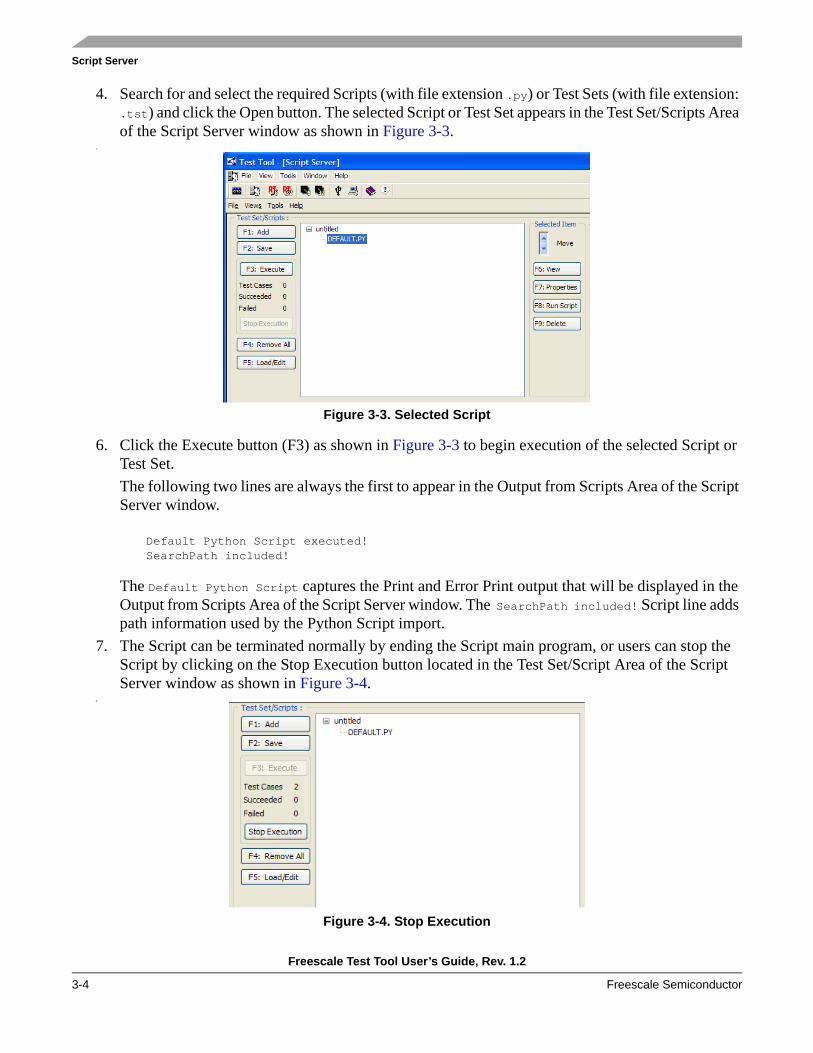
Script Server
Freescale Test Tool User’s Guide, Rev. 1.2
3-4 Freescale Semiconductor
4. Search for and select the required Scripts (with file extension .py) or Test Sets (with file extension: .tst) and click the Open button. The selected Script or Test Set appears in the Test Set/Scripts Area of the Script Server window as shown in Figure 3-3.
5.
Figure 3-3. Selected Script
6. Click the Execute button (F3) as shown in Figure 3-3 to begin execution of the selected Script or Test Set.The following two lines are always the first to appear in the Output from Scripts Area of the Script Server window.
Default Python Script executed!SearchPath included!
The Default Python Script captures the Print and Error Print output that will be displayed in the Output from Scripts Area of the Script Server window. The SearchPath included! Script line adds path information used by the Python Script import.
7. The Script can be terminated normally by ending the Script main program, or users can stop the Script by clicking on the Stop Execution button located in the Test Set/Script Area of the Script Server window as shown in Figure 3-4.
8.
Figure 3-4. Stop Execution

Script Server
Freescale Test Tool User’s Guide, Rev. 1.2
Freescale Semiconductor 3-5
9. The progress and result output is displayed in Test Results area of the Script Server window as shown in Figure 3-5.
Figure 3-5. Test Results
3.5 Adding a Script or Test Set1. Click the Add button and a standard file selection window appears as shown in Figure 3-6. This
allows users to search for Scripts and Test Sets. The File Types (file extensions) are .py for Python Scripts and.tst for Script Server Test Sets. User can select multiple files.
Figure 3-6. Select Script or Test Set

Script Server
Freescale Test Tool User’s Guide, Rev. 1.2
3-6 Freescale Semiconductor
2. Select a Script or a Test Set and click the Open button. The selected script or test set appears in the Test Set/Scripts area of the Script Server window as shown in Figure 3-7.
3.
Figure 3-7. Test Set/Scripts Display Area
NOTESelection order can change when files are inserted by the software in the Test Set tree view.
As show in Figure 3-8, Test Sets can be added and expanded.
Figure 3-8. Test Set Expansion

Script Server
Freescale Test Tool User’s Guide, Rev. 1.2
Freescale Semiconductor 3-7
3.6 Saving a Test Set1. Click the Save button to save and name a test set. The file extension is .tst.2.
Figure 3-9. Save Window
3.7 Test Set (Remove All) The Remove All button retrieves a new but empty Test Set.
NOTENo warning is given and no undo functionality is available.
3.8 Editing a Test SetOnly the Test Set main branch can be changed. That is, only deleting, inserting, and moving Scripts and Test Set items is allowed. Editing is only allowed when the Test Set is created or when using Load/Edit and selecting a Test Set. Selecting multiple Test Sets is not allowed.
3.9 Test Set ItemsWhen users highlight a Test Set file in the Test Set/Scripts area, the following functions are enabled:
• Move• View• Properties• RunScript• Delete

Script Server
Freescale Test Tool User’s Guide, Rev. 1.2
3-8 Freescale Semiconductor
3.9.1 Moving a Test Set ItemHighlight a Test Set item and use the Move arrows to move the selected file up or down the tree as displayed in the Test Set/Scripts area.
NOTEOnly files in the main branch can be moved. The arrows are grayed out when an item that is not in the main branch is selected.
3.9.2 Viewing a Test Set ItemSelecting a Script in the tree view enables the View button (F6). Clicking the View button launches a text editor with the selected Script loaded as shown in Figure 3-10. Only Scripts can be viewed.
Figure 3-10. View Script
3.9.3 PropertiesTo view the properties of a Test Set or a Script, select the file and click the Properties button (F7). The properties window appears as shown in Figure 3-11.
Figure 3-11. Properties Window

Script Server
Freescale Test Tool User’s Guide, Rev. 1.2
Freescale Semiconductor 3-9
NOTEAll information in the Properties Window is read only.
3.9.4 Running a Single Test Set ScriptUsers can run one Test Set Script at a time. Select the Script and click the Run Script button (F8). Users can stop script execution by clicking the Stop Execution button or wait until the script completes execution on its own. The Run Script button will only run a script and not a main branch Test Set.
3.9.5 Deleting a Test Set ItemTo remove an item from the main branch of a Test Set, select the item and click the Delete button (F9).
NOTENo warnings are displayed and no undo functionality is available.
3.10 Execute OptionsThe Execute Options consists of the following option sets:
• Execute Test Sets• Mail• Search Path
Figure 3-12. Execute Options Display Area
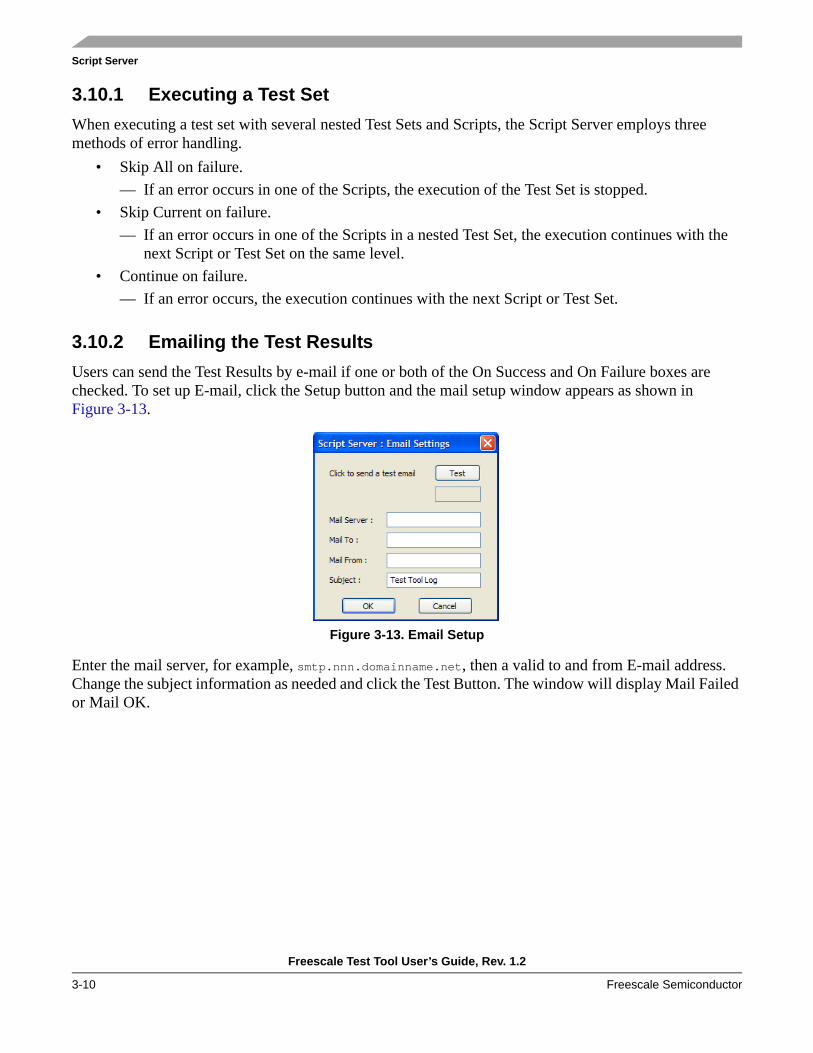
Script Server
Freescale Test Tool User’s Guide, Rev. 1.2
3-10 Freescale Semiconductor
3.10.1 Executing a Test SetWhen executing a test set with several nested Test Sets and Scripts, the Script Server employs three methods of error handling.
• Skip All on failure. — If an error occurs in one of the Scripts, the execution of the Test Set is stopped.
• Skip Current on failure. — If an error occurs in one of the Scripts in a nested Test Set, the execution continues with the
next Script or Test Set on the same level. • Continue on failure.
— If an error occurs, the execution continues with the next Script or Test Set.
3.10.2 Emailing the Test ResultsUsers can send the Test Results by e-mail if one or both of the On Success and On Failure boxes are checked. To set up E-mail, click the Setup button and the mail setup window appears as shown in Figure 3-13.
Figure 3-13. Email Setup
Enter the mail server, for example, smtp.nnn.domainname.net, then a valid to and from E-mail address. Change the subject information as needed and click the Test Button. The window will display Mail Failed or Mail OK.

Script Server
Freescale Test Tool User’s Guide, Rev. 1.2
Freescale Semiconductor 3-11
3.10.3 Search PathTo set search paths, click the Setup Search Path button and the Python Search Path window appears as shown in Figure 3-14. Notice the default locations and the ability to enter a custom user search path.
Figure 3-14. Search Path
3.10.4 Script Output and ResultsThe Script Server offers two display views, one for test results and execution progress, and one for output from scripts and Test Tool communication flow.
Figure 3-15. Test Results Window
3.10.4.1 Test Result OutputThe Display Test Results checkbox enables the output of the Test Results to appear in the view area. A timestamp can be added by activating the Display Timestamp checkbox. The view is cleared by clicking on the Clear button or pressing: <Alt> + C.
It is also possible to record the test results output to a file. Check the Save Results in File checkbox and enter a file name where the data will be saved.

Script Server
Freescale Test Tool User’s Guide, Rev. 1.2
3-12 Freescale Semiconductor
3.10.4.2 Script OutputThree check boxes control the Script output view. The Display Script Output starts and stops the update of the view. Timestamps are added if the Display Timestamp box is checked.
Enter a filename and set the Save output in file checkbox to save the output in a file. The file is placed into the py_output folder in the default Test Tool folder path.
Figure 3-16. Script Output Window
A number of check boxes control the Script output view. The Display Script Output option starts and stops the update of the view. Timestamps are added if the Display Timestamp box is checked.
Enter a filename and set the Save output in file checkbox to save the output in a file. The file is placed into the py_output folder in the default Test Tool folder path.
The Scripts send commands and receive events from devices. These commands and events can be displayed by checking the Display TX Packets and Display RX Packets check boxes. The number of sent and received packets is also displayed.
The Decode Packets checkbox allows Script Server to display the type of every packet sent and received based on the command set loaded from the XML directory.
As shown in Figure 3-17, the Display Timestamp option is set, two commands have been sent and two events received.
Figure 3-17. Script Output Example

Script Server
Freescale Test Tool User’s Guide, Rev. 1.2
Freescale Semiconductor 3-13
The display format is somewhat similar for commands and events. The first command is interpreted as follows:
The second one is the event.
3.11 Python ScriptsThe Script Server provides functions to access the Test Tool API. These functions are placed into the pyapi Python module. In order to make use of all the functionality of ZTC application on the boards, other Python modules should be included. For working with the ZigBee ZTC application, the user should include ztcsys.py.
Refer to the bundled example scripts to see exactly what modules should be included when creating and running user scripts. The example scripts provide also the best way of understanding the usage of
The pyapi module does the actual interfacing with the Test Tool, but the user has to use higher level primitives which are presented by ztcsys. To write their own scripts, users must understand the basic concepts that Test Tool uses:
1. Sending commands to a device. These kind of functions are used to assemble and send a command packet to a device the same way the command console does. An example of such a command is MLME_GETrequest(DeviceID, PIBAttribute).
2. All commands usually trigger a response from the device which translates into an API event. The user should use the look_for and wait_for functions, to retrieve and examine the event he/she is interested to get from the event queue. The look_for function searches the entire event
Device Handle = 1
Command Group = A3
Command Opcode
= 00 (ZTC-ModeSe-lect.Request)
Length = 0A
Payload = 01 01 01 00 00 00 00 00 00 00
Device Handle = 1
Command Group = A4
Command Opcode
= 00(ZTC-ModeSe-lect.Confirm)
Length = 01
Payload = 00 = Success

Script Server
Freescale Test Tool User’s Guide, Rev. 1.2
3-14 Freescale Semiconductor
queue returning either the respective event, if meanwhile occurred, or None. The wait_for function works in a similar manner, except that it blocks the script execution for a certain amount of time, specified by one of its parameters, while waiting for the desired event to occur.
3. An event is a Python dictionary, consisting of “Opcode”, and “OpcodeGroup”, end either a “Data” or “Status” member, depending on the response type from the device. These last two members are of interest for the user, because they contain the actual payload of the response. The Data member is usually a list of bytes. The Status member is a byte indicating, for instance, success or failure of a certain command.Still, the events in ztcsys.py present a particular structure for each kind of event, with separate dictionary items for each parameter of the response.For instance the _MLME_GETconfirm event contains a PIBAttribute and a PIBAttributeValue member.
When using the Test Tool API all functions must have pyapi. as prefix. However, these are seldom used. The functions in ztcsys effectively encapsulate the ZTC primitives.
In order to offer the user a real testing environment, the well known Python Unittest module is bundled with the Script Server. This provides a convenient way of running tests and recording the results.
3.11.1 Communication Between Scripts and DevicesThe devices can be connected by UART/USB or Winsockets. The devices are listed in the Test Tool List of Devices.
NOTEIt is not possible to use the BDM when running the Script Server.
To communicate to a device from a Script, the Script must start the device and retrieve a handle.
For example: LocalDeviceHandle = pyapi.StartDevice(DEV_ZIGBEE)
For example: LocalDevice = pyapi.StartDevice(0)
For example: pyapi.StopDevice(LocalDevice)SendCommand.
StartDevice: Starts the communication with the device and returns a handle to be used for communication.
Returns: 0 on failure, else a handle to the device.
StopDevice: Stops the communication with the device and releases the handle.
Parameter: unsigned short DeviceId
Returns: 0 (false) on failure , else 1 (true)

Script Server
Freescale Test Tool User’s Guide, Rev. 1.2
Freescale Semiconductor 3-15
3.11.1.1 SendCommandThe SendCommand sends a command to a device.
3.11.1.2 SendToolCommandThe SendToolCommand sends a command to all or one Test Tool API clients – see CallBack.
3.11.1.3 SendToolEvent
Parameters: unsigned short DevIdunsigned char *pCmdunsigned short Length
Parameter description: DevId is the Test Tool API for a device, the handle value is returned calling pyapi.StartDevice.pCmd is a pointer to an array of bytes holding the command.Length is the number of bytes in the command buffer pCmd.
Return value: Returns true (1) on success , false (0) on failure.
Function: RegisterToolCommands.
Parameters: unsigned short DevIdunsigned char *pCmdunsigned short Length
Parameter description: If DevId = 0 the command is send to all internal Test ToolAPI Clients. If DevId>0 the command is send to the device with the specified handle value. pCmd is a pointer to an array of bytes holding the command. Length is the number of bytes in the command buffer pCmd.
Note:The handle value was returned calling pyapi.StartDevice.
Return value: Returns true (1) on success , false (0) on failure.
Function: SendToolEvent.
Parameters: unsigned short DevIdunsigned char *pCmdunsigned short Length
Parameter description: DevId = 0. Values above 0 is used by devices or managed by the Test Tool API.pEvent is a pointer to an array of bytes holding the event.Length is the number of bytes in the command buffer pEvent.
Return value: Returns true (1) on success , false (0) on failure.

Script Server
Freescale Test Tool User’s Guide, Rev. 1.2
3-16 Freescale Semiconductor
3.11.2 Callback FunctionsThis group of functions must be used to receive events sent by the Test Tool API. A call can look like the following:
pyapi.RegisterToolEvents(__ToolEvent)
All Events have three parameters: • unsigned short DevId• unsigned char *pData • unsigned short Length.
All Callback Functions takes a Handle (pointer) to a CallBack function (PyObject).
3.11.2.1 Device EventsStart and stop receiving events from a device.
3.11.2.2 Tool Events
RegisterDeviceEvents Use to get events from a device, remote or internal.
Parameter Void * pFunc
Parameter Description pFunc must be a pointer to a callback function.
Return Value Returns true (1) on success , false (0) on failure.
DeregisterDeviceEvents Use to stop receiving events from the devices.
Parameter Void * pFunc
Parameter Description pFunc must be a pointer to a callback function.
Return Value Returns true (1) on success , false (0) on failure.
RegisterToolEvents Use to get Test Tool events, remote or internal.
Parameter Void * pFunc
Parameter Description pFunc must be a pointer to a callback function.
Return Value Returns true (1) on success , false (0) on failure.
DeregisterToolEvents Use to stop getting Test Tool events.
Parameter Void * pFunc
Parameter Description pFunc must be a pointer to a callback function.
Return Value Returns true (1) on success , false (0) on failure.

Script Server
Freescale Test Tool User’s Guide, Rev. 1.2
Freescale Semiconductor 3-17
3.11.2.3 Tool Commands
3.11.3 Test Result from Python ScriptTwo functions are used to display output from Scripts in the Test Result view.
3.11.4 Python Script Print OutputThe Python standard print function can be used to display tests in the Script output area of the Script Server window. Error prints are also displayed. Errors in Scripts are displayed with a description of the error, the file, and the line (as an aid for where to look for the error).
RegisterToolCommands Use to receive Test Tool commands, remote or internal.
Parameter Void * pFunc
Parameter Description pFunc must be a pointer to a callback function.
Return Value Returns true (1) on success , false (0) on failure.
DeRegisterToolCommands Use to stop receiving Test Tool commands.
Parameter Void * pFunc
Parameter Description pFunc must be a pointer to a callback function.
Return Value Returns true (1) on success , false (0) on failure.
SetTestResult Sets the result of a Script
Parameter integer
Result values PyTR_Failure = 0x00,PyTR_Success = 0x01,PyTR_Unknown = 0x02,PyTR_NoResult = 0x03, above this = Failure
WriteTestResult
WriteTestResult Used to print information in text format in the Test Result view.
Parameter Char * TextString

Script Server
Freescale Test Tool User’s Guide, Rev. 1.2
3-18 Freescale Semiconductor

Freescale Test Tool User’s Guide, Rev. 1.2
Freescale Semiconductor 4-1
Chapter 4 Firmware LoadersThis chapter describes the two firmware loaders that come with the Test Tool, the HCS08 Firmware Loader and the MC1322x Firmware Loader. They can flash new firmware into Freescale ZigBee evaluation boards and allow users to flash different application code into these boards from Test Tool without the need for other software.
4.1 Introducing the Firmware LoadersThe HCS08 Firmware Loader only operates with Freescale’s HCS08 architecture microcontroller based boards such as the 13192-EVB, SARD, 1321x-SRB, and 1321x-NCB boards. The HCS08 Firmware Loader only supports the S-record (.S19) files and uses the USB Multilink device to upload the content of the .s19 files into microcontroller’s FLASH.
The MC1322x Firmware Loader only operates with Freescale’s 1322x-NN, 1322x-SN, 1322x-SRB, 1322x-LPB and 1322x-USB development boards, which are based on Freescale’s MC1322x ARM7 based third-generation ZigBee platform which incorporate a complete, low power, 2.4 GHz radio frequency transceiver, 32-bit ARM7 core based MCU, and other features in a single package.
The MC1322x Firmware Loader only supports binary (.bin) files and makes use of the ARM7 microcontroller’s serial communication interface and the embedded bootloader in ROM, so no additional hardware is required, with the exception of the communication cable. The MC1322x Firmware Loader is capable of uploading applications into either the MC1322x RAM or FLASH.
4.2 HCS08 Firmware LoaderTo use this tool, a USB Multilink device is needed. Users must be able to upload the content of an S record file (.s19) into the microcontroller FLASH. Immediately after uploading, users have the opportunity to view and modify the parameters stored in the non-volatile memory (NVM), such as the MAC address, the transmitting power level on each channel, and the default crystal trim value among others.
4.2.1 HCS08 Firmware Loader Hardware and Software ConsiderationsNOTE
The procedures as described in this chapter assume that the BDM drivers are already installed on the PC.
Users must first register the BDM as one of the communication devices used by Test Tool. To do this, perform the following tasks:
1. Connect the BDM to one of the USB ports of the PC.2. Launch Test Tool. (See Chapter 1, “Introduction”.)

Firmware Loaders
Freescale Test Tool User’s Guide, Rev. 1.2
4-2 Freescale Semiconductor
3. From the Test Tool main menu bar, click on Tools -> Communication Settings.4. The List of Devices window appears as shown in the background of Figure 4-1.5. Click on the Add Internal button. The Device Settings window appears as shown in the foreground
of Figure 4-1.6. Check the USB BDM radio button and click on the OK button. A new device titled, ZigBee BDM
(USB) appears in the list of devices. 7. In the Device Settings window, click the Close button.
Figure 4-1. Registering the USB BDM using Test Tool
4.2.2 Starting the HCS08 Firmware Loader1. From the Test Tool menu bar, click on View -> Firmware Loader->HCS08 Firmware Loader.
The Firmware loader window appears (Figure 4-4), but users are first required to select a communication device from a list as it appears in the Select Device window (Figure 4-2). This list usually displays the registered items like those described in Section 4.2.1, “HCS08 Firmware Loader Hardware and Software Considerations”. In this particular case, the list only displays the registered USB Multilink device.
2. Ensure that the USB Multilink is connected to both the PC and to the board and that the board is powered on. Select the device from the list and click on the OK button as shown in Figure 4-2.

Firmware Loaders
Freescale Test Tool User’s Guide, Rev. 1.2
Freescale Semiconductor 4-3
Figure 4-2. Device Selection List
NOTEIf the USB Multilink device was left unconnected or the board was not powered up before starting the Firmware Loader, an error message appears that asks users to check the condition of the board and/or the BDM.
Figure 4-3. Firmware Loader Error Message
3. The Firmware Loader main window appears as in Figure 4-4.

Firmware Loaders
Freescale Test Tool User’s Guide, Rev. 1.2
4-4 Freescale Semiconductor
Figure 4-4. Firmware Loader Main Window
4.2.3 HCS08 Firmware Loader Main Window OverviewThe Firmware Loader window has the following functionality:
• The check boxes in the upper half of the window allow users to set parameters that affect Firmware Loader behavior and have the following functionality.— Overwrite production data in FLASH— The program expects to find data in the non-volatile
memory area, such as the MAC address, serial number, and some other functional values which should not be erased during a software upgrade. The default approach is to try and preserve these values. By selecting this option, the Firmware Loader assumes that this data can be safely erased. Always select this option if the microcontroller’s FLASH was previously completely erased, or the non-volatile memory does not contain any data.
— Do not reset after upload — After an upload, the system usually performs a software reset. Choosing this option prevents the reset from taking place.
NOTEThe user should always check this box if further editing of the parameters stored in the non volatile memory is needed. After reset, the content of the FLASH will always be protected from being read or changed.
— Skip firmware checksum verification — Usually the checksum in the S19 file is compared against the checksum of the flashed content. Choosing this option skips the checksum verification.

Firmware Loaders
Freescale Test Tool User’s Guide, Rev. 1.2
Freescale Semiconductor 4-5
• The lower half of the window contains a list of applications that are ready to be flashed. The list is populated with all the .s19 files currently placed in the default S19 subfolder which is located in the Test Tool installation folder.
• The Upload button uploads the application file selected in the list.• The NVRam Info button opens a window that allows further operations on the NVM.• At the bottom of the window, the progress bar shows how the upload process is progressing.
Further information about the upload process is also displayed in the window’s status bar.
4.2.3.1 HCS08 Firmware Loader Menu Bar OverviewThis section describes the Firmware Loader menu bar options available from the Firmware Loader main window.File Option The File option allows users to exit (close) the Firmware Loader program.Tools Option The Tools -> Option allows users to select the Upload and the NV-RAM options.
From the menu bar, the Upload option allows users to work with files not contained in the default S19 folder. (S19 files which do not appear in the Application files list.) The NV-RAM Info menu bar option has the same functionality as the NV-RAM info button.
Help Option The Help -> About option allows users to view Firmware Loader version information. More Help options are available from the Test Tool menu bar.
4.2.4 Using the HCS08 Firmware LoaderThis section describes how to choose HCS08 Firmware Loader options, upload files, and use the NV RAM window.
1. Start the HCS08 Firmware Loader as described in Section 4.2.2, “Starting the HCS08 Firmware Loader”.
2. Verify the state of the Optional firmware upload settings check boxes. If the microcontroller is erased or the FLASH contains some third party software, do not forget to select the Erase production data.. option. The same thing applies if the NVM is not used or has some other layout.
3. There are two ways to choose the file to be uploaded, depending on the location of the file.a) If the file is an example file and has been delivered together with the Test Tool, its name should
appear in the Application Files list. Select it from there and click on the Upload button to upload the file.
b) If the file is placed in some other folder, use the Firmware Loader’s menu bar and click on Tools -> Upload... A standard Windows Open file window appears that allows users to search for and select an S19 file that is not in the default location. The upload operation starts immediately after the window is closed.
NOTEPressing the Upload button in the Firmware Loader window (not the menu bar option), immediately begins the upload of the file chosen in the Application Files list. If the list is empty, nothing happens.
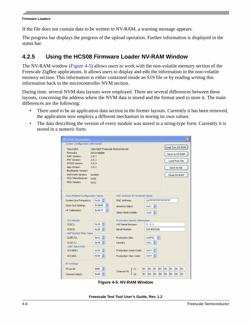
Firmware Loaders
Freescale Test Tool User’s Guide, Rev. 1.2
4-6 Freescale Semiconductor
If the file does not contain data to be written to NV-RAM, a warning message appears.
The progress bar displays the progress of the upload operation. Further information is displayed in the status bar.
4.2.5 Using the HCS08 Firmware Loader NV-RAM WindowThe NV-RAM window (Figure 4-5) allows users to work with the non-volatile memory section of the Freescale ZigBee applications. It allows users to display and edit the information in the non-volatile memory section. This information is either contained inside an S19 file or by reading writing this information back to the microcontroller NVM section.
During time, several NVM data layouts were employed. There are several differences between these layouts, concerning the address where the NVM data is stored and the format used to store it. The main differences are the following:
• There used to be an application data section in the former layouts. Currently it has been removed, the application now employs a different mechanism in storing its own values.
• The data describing the version of every module was stored in a string-type form. Currently it is stored in a numeric form.
Figure 4-5. NV-RAM Window

Firmware Loaders
Freescale Test Tool User’s Guide, Rev. 1.2
Freescale Semiconductor 4-7
The NV-RAM window can be displayed in three ways.• When users double-click on a file in the Application Files list of the Firmware Loader window.• When users click on the NV-RAM Info button in the Firmware Loader window• When users employ the Tools option from the Firmware Loader window. Using the Tools option
makes the NV-RAM window appear with the fields in a default state.
The software tries to read the NVM information from the selected file. A warning is issued on failure.
Some fields of the NV-RAM window are not active because of different memory layouts.
The NV-RAM window allows users to perform the following operations:• Reading the information from a file — This can either be previously saved by using the NV-RAM
window, or can be some other file containing a Freescale ZigBee application. To achieve this, click on the Load from file button and select the file from the standard file selection window that appears. The file should have a SREC format.
• Saving the NVM information to a file — Click on the Save to File button and select the target file.• The Load from NV-RAM button reads the NV-RAM section of the microcontroller as shown in
Figure 4-6. An error message is issued if the microcontroller does not have a valid NVM section or if the FLASH is protected.
• The Save to NV-RAM button writes back the NV-RAM section of the microcontroller. An error message is issued if the microcontroller does not have a valid NVM section or if the FLASH is protected. Users should employ caution using this option.

Firmware Loaders
Freescale Test Tool User’s Guide, Rev. 1.2
4-8 Freescale Semiconductor
4.3 MC1322x Firmware LoaderThe MC1322x Firmware Loader allows users to upload the contents of a binary file (.bin) into the MC1322x RAM or FLASH memory. Both of these operations make use of the embedded bootloader located in the MC1322x microcontroller’s ROM. Users do not need any extra hardware. The uploading procedure uses the MC1322x microcontroller’s serial interface, so a regular USB or serial communication cable, depending on what the board supports for serial communication, is enough to perform the task.
4.3.1 Starting the MC1322x Firmware LoaderPerform the following tasks to start and run the MC1322x Firmware Loader.
1. From the Test Tool main window menu bar, start the MC1322x Firmware Loader by clicking onView -> Firmware Loader->1322x Firmware Loader. The Select Device window appears as shown in Figure 4-6.
2. In the Select Device window, choose the correct COM port from the list of registered serial devices as shown in Figure 4-6.
Figure 4-6. “Select Device” Window
3. Select the device that corresponds to the attached MC1322x based board. Users must ensure that the corresponding baud rate is 115200. See Section 2.3.1, “Configure Serial Ports” for information on how to set the baud rate and other serial communication options.If communication with the device starts successfully, the MC1322x Firmware Loader main window appears as shown in Figure 4-7.
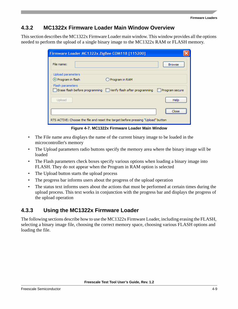
Firmware Loaders
Freescale Test Tool User’s Guide, Rev. 1.2
Freescale Semiconductor 4-9
4.3.2 MC1322x Firmware Loader Main Window OverviewThis section describes the MC1322x Firmware Loader main window. This window provides all the options needed to perform the upload of a single binary image to the MC1322x RAM or FLASH memory.
Figure 4-7. MC1322x Firmware Loader Main Window
• The File name area displays the name of the current binary image to be loaded in the microcontroller's memory
• The Upload parameters radio buttons specify the memory area where the binary image will be loaded
• The Flash parameters check boxes specify various options when loading a binary image into FLASH. They do not appear when the Program in RAM option is selected
• The Upload button starts the upload process• The progress bar informs users about the progress of the upload operation• The status text informs users about the actions that must be performed at certain times during the
upload process. This text works in conjunction with the progress bar and displays the progress of the upload operation
4.3.3 Using the MC1322x Firmware LoaderThe following sections describe how to use the MC1322x Firmware Loader, including erasing the FLASH, selecting a binary image file, choosing the correct memory space, choosing various FLASH options and loading the file.

Firmware Loaders
Freescale Test Tool User’s Guide, Rev. 1.2
4-10 Freescale Semiconductor
4.3.3.1 Uploading Application Files
To upload an application from a binary file into the MC1322x based board, perform the following tasks.1. Erase the FLASH memory. See Section 4.3.3.2, “Manually Erasing the FLASH”.
NOTEIf the MC1322x FLASH contains a valid application, uploading to either FLASH or RAM will only be possible after the FLASH is erased. Otherwise, communication with the board will not occur and the application that was already on the board will be launched at startup.
2. Select the binary file to upload. See Section 4.3.3.3, “Selecting the Binary Image”.3. Select the target memory space (RAM or FLASH). See Section 4.3.3.4, “Selecting the Upload
Parameters”.4. Select the FLASH parameter options. See Section 4.3.3.5, “Flash Parameter Option Definitions”.5. Press the reset button on the target board. See Section 4.3.3.6, “Uploading the Image File”.6. Click on the upload button to load the file. See Section 4.3.3.6, “Uploading the Image File”.
4.3.3.2 Manually Erasing the FLASH
Before trying to upload a binary image to the MC1322x based board, ensure that the FLASH was previ-ously erased. Otherwise, communication with the board will not even be initiated.
To erase the FLASH, perform the following tasks:1. Make sure the board is powered off.2. Use 2 (two) jumpers and short together the pin pairs marked VREFH (ADC2_VrefH) and VREFL
(ADC2_VrefL) on the 22x board. These pin pairs are clearly marked on the 22x boards.3. Power on the board.4. After a few seconds, power off the board.5. Remove the jumpers.6. After performing this procedure, restart the MC1322x Firmware Loader and select the device again
from the Select Device window as shown in Figure 4-6.
4.3.3.3 Selecting the Binary Image
A binary image file (*.bin) can be generated by the IAR Embedded Workbench for ARM IDE when the user compiles an application for MC1322x based applications. To select a binary image file, perform the following tasks:
1. After selecting and connecting to a device, from the MC1322x Firmware Loader main window, click on the Browse button. The Open Binary File window appears.
2. In the Open Binary File window, select the *.bin file and click OK. If the file successfully loads, its name appears in the File name area.

Firmware Loaders
Freescale Test Tool User’s Guide, Rev. 1.2
Freescale Semiconductor 4-11
4.3.3.4 Selecting the Upload ParametersUsing the radio buttons located in the Upload Parameters section of the MC1322x Firmware Loader main window, users can choose to upload the binary image file to either the FLASH or RAM. The default option uploads the image file to FLASH because the content of the RAM is lost after a board reset.
4.3.3.5 Flash Parameter Option DefinitionsErase FLASH before programming — Selecting this option erases the FLASH before actual programming.
This option is useful to clear the FLASH only if the FLASH was left in a corrupt state by a previous programming process. If the FLASH contains a valid application, communication with the board is not initiated, and users must manually erase the FLASH as described in Section 4.3.3.2, “Manually Erasing the FLASH” .
Verify FLASH after programming — Selecting this option reads the content of the FLASH from the board after programming and compares it to the original image file to verify that the programming was done correctly.
Program secure Selecting this option programs the FLASH using a secure mode that does not allows the FLASH content to be dumped or altered via the JTAG/Nexus interface. It basically disables the corresponding JTAG/Nexus pins on the board.
4.3.3.6 Uploading the Image FileNOTE
Before clicking the Upload button, users must press the Reset (RST) button on the board. The bootloader is initialized and is then able to sense the incoming UART communication by examining the state of the RTS line.
Clicking the Upload button starts the actual board programming process. When programming is complete, the corresponding message is displayed in the status bar at the bottom of the MC1322x Firmware Loader main window. Depending on the state of the FLASH parameter check boxes, the messages displayed on the status bar change according to the operation in progress.

Firmware Loaders
Freescale Test Tool User’s Guide, Rev. 1.2
4-12 Freescale Semiconductor

Freescale Test Tool User’s Guide, Rev. 1.2
Freescale Semiconductor 5-1
Chapter 5 Radio TestThe Radio Test program allows users to test the radio link between two boards. Radio Test can allows users to accomplish the following:
1. Radio Testing2. Packet Error Rate (PER) estimation3. Setting up various related parameters on the board such as crystal trim4. Inspecting and editing the transceiver registers (HCS08 based transceivers only)
NOTEThe PER must be less than 1% sending packets with 20 bytes payload to meet the 802.15.4 specification.
5.1 Radio Test Hardware and Software ConsiderationsUsers must have at least one board programmed with the ZigBee Test Client (ZTC) program. Two boards are required to perform the PER test and these two boards must be connected to the same instance of Test Tool. See Chapter 4, “Firmware Loaders”, for information on how to load applications to a board. Also, the two boards must employ the same type of transceivers (they both must be either HCS08 based, or MC1322x ARM7 based). However, because the PER only employs MAC commands (which work the same regardless of the architecture being used), the PER test allows the pairing of boards based on different architectures.
NOTEFor a PER test, users may want to have the second board located a certain distance away from the first board, usually further away than the standard USB cable length will allow. In this case, users will have to make use of Test Tool’s ability to use remote ports on TCP sockets. There may be noticeable delays due to the TCP latency, but users will still be able to conduct PER tests. See Section 5.5, “Running Radio Test on Two Computers” for more information.
It is not possible to use the BDM when running Radio Test.

Radio Test
Freescale Test Tool User’s Guide, Rev. 1.2
5-2 Freescale Semiconductor
5.2 Running Radio TestTo run Radio Test, perform the following tasks.
1. Launch the Radio Test program from the Test Tool menu bar. Click on View -> ZigBee Radio Test and then depending on the device being used, select either “HCS08 Radio Test” or “MC1322x Radio Test”. The Select Device window appears as shown in Figure 5-2.
Figure 5-1. Select Device Window
2. Choose a device. If a device has not been added, see 2.3.1, “Configure Serial Ports”.3. Click the OK button and the Radio Test main window appears as shown in Figure 5-2.
Figure 5-2. HCS08 Radio Test Main Window

Radio Test
Freescale Test Tool User’s Guide, Rev. 1.2
Freescale Semiconductor 5-3
5.3 Radio Test Interface OverviewThe Radio Test interface provides a Evaluation and Developing tab that allows users to test and setup a device, set the device into continuous transmit or receive modes and monitor various Packet Error Rate (PER) information. The Qualification tab allows users to set various receive and transmit parameters, set and monitor power amplifier levels, and monitor various Packet Error Rate (PER) information.
See the Radio Test online help and Section 5.6, “Radio Test Advanced features” for more detailed inter-face information.
5.3.1 Using the Radio Test Menu BarThis section describes the Radio Test menu bar options available from the Radio Test main window.
5.3.1.1 File OptionThe File option allows users to exit (close) the Radio Test program.
5.3.1.2 Views OptionThe Views option provides the following functionality:
• Allows users to expand or contract the Advanced view in the Radio Test main window (same as the Advanced view button).
• Save, Print, or Clear the Rx/Tx view as shown in the Radio Test main window.
5.3.1.3 Tools OptionThe Tools -> Options allows users to set the following options:
• Maximum number of items to allow in the Rx/Tx view area• The ability to automatically expand displayed commands and events
5.3.1.4 Help OptionThe Help -> About option allows users to view Radio Test version information. More Help options are available from the Test Tool menu bar.
5.4 Running Radio Test on a Single ComputerTo run Radio Test on a single computer, perform the following steps:
1. Launch the Radio Test program from the Test Tool menu bar by clicking on View -> ZigBee Radio Test. Users are required to select the port for the first device they use.
2. Users can check the serial connection to the device (Evaluation and Development tab) by pressing the Send Ping button.

Radio Test
Freescale Test Tool User’s Guide, Rev. 1.2
5-4 Freescale Semiconductor
3. Select the required channel to perform testing by clicking on the Qualification tab (Figure 5-3). Users can switch between three channels, one on each side of the allocated band, and one in the middle.
Figure 5-3. Setting the Channel in the Qualification Tab
4. As an alternative, clicking the Advanced View button allows users to choose any of the standard ZigBee channels to perform the test. If using the Advanced View option, the channel list is also available in the Evaluation & Developing tab as shown in Figure 5-4.
Figure 5-4. Choosing a Channel for Performing the Test
5. Set the Coordinator, End Device short addresses, and the PANID to the desired values. Users can use the defaults if they are sure that they do not interfere with other networks.

Radio Test
Freescale Test Tool User’s Guide, Rev. 1.2
Freescale Semiconductor 5-5
6. Set up the payload size and the total number of packets that need to be transmitted. Click on the Advanced View tab to see additional fields as shown in Figure 5-5.The slider also allows users to specify the payload size. The data format can only be “random” or “manual”. If users select “manual”, they will have to fill in the “data” field with the values of the payload bytes. They should be entered as an array of concatenated hexadecimal values. The following example describes a 5 byte payload:
0xa1c3441234
Users will only be able to type as many values as they specified for the payload size. If the value entered is less than the payload size, the remainder is filled with zeros.
Figure 5-5. Advanced view
7. Press the Start as Coordinator button to set the first board as the Coordinator.8. Press the Start as Device button. Users are asked if the Coordinator was started. The Select Device
window appears and users are required to select the port to which the second device is connected.9. During the test, users can see the current PER and the success rate of the current and previous tests.
5.5 Running Radio Test on Two Computers1. Start Test Tool on both computers. Connect one device to each computer and, if they are not already
registered, register the devices using the Tools -> Communication Settings option.2. On one of these computers, use the Tools -> Communication Settings option and write down the
port number associated to the device (which appears in the Location column). It is usually 1000x. Do not start the PER Test or Command Console or anything else on this computer. Leave Test Tool running in its initial state. Users must ensure that this TCP port is accessible from the outside. If a firewall is installed on this computer it must be set up to allow Test Tool to act as a server.
3. Find the IP address on the same computer. There are numerous ways to do this. For example, start DOS by going to the Windows Start menu and click Run..., then enter cmd in the text box. When the command prompt appears, enter ipconfig and press the Enter key. Examine the output from this command.
4. On the second computer select Tools -> Communication Settings. Press the Add External button. Select the ZigBee device as the device type. Write down the IP address (found in Step 3) in the host box. Write down the port number of the other device in the port box (also found in Step 3). Now the two devices are present on the same computer.
5. Start the PER test only on the second computer. To start, select one of the two devices. Then set up the test parameters. Then press the Start as coordinator option and the device will start as the Coordinator. Then press the Start as device button and select the other device. The PER test will start.There will be less throughput due to latency in the LAN, but users will still be able to conduct a reliability test.
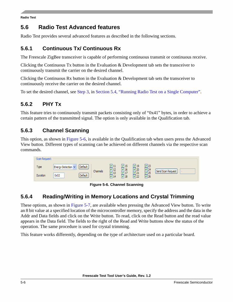
Radio Test
Freescale Test Tool User’s Guide, Rev. 1.2
5-6 Freescale Semiconductor
5.6 Radio Test Advanced featuresRadio Test provides several advanced features as described in the following sections.
5.6.1 Continuous Tx/ Continuous RxThe Freescale ZigBee transceiver is capable of performing continuous transmit or continuous receive.
Clicking the Continuous Tx button in the Evaluation & Development tab sets the transceiver to continuously transmit the carrier on the desired channel.
Clicking the Continuous Rx button in the Evaluation & Development tab sets the transceiver to continuously receive the carrier on the desired channel.
To set the desired channel, see Step 3, in Section 5.4, “Running Radio Test on a Single Computer”.
5.6.2 PHY TxThis feature tries to continuously transmit packets consisting only of “0x41” bytes, in order to achieve a certain pattern of the transmitted signal. The option is only available in the Qualification tab.
5.6.3 Channel ScanningThis option, as shown in Figure 5-6, is available in the Qualification tab when users press the Advanced View button. Different types of scanning can be achieved on different channels via the respective scan commands.
.
Figure 5-6. Channel Scanning
5.6.4 Reading/Writing in Memory Locations and Crystal TrimmingThese options, as shown in Figure 5-7, are available when pressing the Advanced View button. To write an 8 bit value at a specified location of the microcontroller memory, specify the address and the data in the Addr and Data fields and click on the Write button. To read, click on the Read button and the read value appears in the Data field. The fields to the right of the Read and Write buttons show the status of the operation. The same procedure is used for crystal trimming.
This feature works differently, depending on the type of architecture used on a particular board.

Radio Test
Freescale Test Tool User’s Guide, Rev. 1.2
Freescale Semiconductor 5-7
For the HCS08 based boards, there is only one value to set for crystal trimming as shown in Figure 5-7.
Figure 5-7. Read/Write Memory Locations and Crystal Trimming (HCS08 Based Boards)
For the MC1322x based boards, there are two values to set, as shown in Figure 5-8. In addition, when reading or writing memory locations on MC1322x microcontrollers, the Addr and Data fields are set to use 32 bit values.
Figure 5-8. Crystal Trimming (MC1322x Based Boards)
5.6.5 Radio Registers Window (HCS08 only)To see a graphical layout of the radio registers, press the Radio Registers button. The Radio Registers window appears as shown in Figure 5-9. This window allows users to view and set various bits and review radio register attributes.
The Radio Registers Window is an interactive version of the SPI register table as shown in the various Freescale 2.4 GHz low power ZigBee transceiver family data sheets. Users can read and write data to and from each SPI register. Additional information about each data element is displayed by hovering the mouse over the chosen item.
Data in each register can be read or written according to the way each register is organized. All read and written values are in hexadecimal form.

Radio Test
Freescale Test Tool User’s Guide, Rev. 1.2
5-8 Freescale Semiconductor
Figure 5-9. Radio Registers Window
NOTEUsers must perform a read operation of a register before changing the values in that register.
To perform a read operation on a single register, click on the Read button located to the right of the register index number. To read all register values at once, click the Read All button.
Change the value of a single register by pressing the Write button, located to the right of the register content area.
To see the remainder of the register stack, use the scroll bar located to the right of the window. The registers that are particular to a certain chip model (1321x) are located at the bottom of the window.
When finished with editing the registers, click the Close Radio Register button. All of the read/write actions are added to the Rx/Tx area in the parent Radio Test window, and an additional three read register operations are performed on close. The last three read operations are performed to update the current Channel, and PA Level settings.