Free-Flying Altimeter Study Final Report June 2003
39
Free-Flying Altimeter Study Final Report June 2003 R. K. Raney Johns Hopkins University Applied Physics Laboratory 11100 Johns Hopkins Road Laurel, MD 20723-6099 [email protected] Sponsor: Dr. Walter H. F. Smith NOAA Laboratory for Satellite Altimetry Code E/RA31 1335 East-West Highway, room 5408 Silver Spring, MD 20910-3282 Order No. DG133E-02-SE-0848 NOAA NEED3000-2-00151 Final Report, as required under Task LFR01
Transcript of Free-Flying Altimeter Study Final Report June 2003


12 June 2003 LFR01
TIN: 52-0595111 Ref: DG133E-02-SE-0848
To: Dr. Walter H. F. Smith NOAA Lab for Satellite Altimetry, code E/RA31
1335 East-West Highway, room 5408 Silver Spring MD 20910-3282
From: R. Keith Raney Johns Hopkins University Applied Physics Laboratory
FINAL REPORT Free-Flying Altimeter Study
ABYSS was a proposal in 2001-2002 to NASA by NOAA and the Johns Hopkins University Applied Physics Laboratory (JHU/APL) for an altimeter to be mounted on an instrument pallet at the International Space Station (ISS) [Smith, 2002]. The ISS orbit inclination (~51o) and non-repeat coverage would have been nearly ideal for the ABYSS mission, which was to provide high-resolution maps of oceanic gravity anomalies, from which bathymetric charts can be derived. Data from ABYSS would have provided approximately a four-fold improvement over gravimetry previously gathered by Geosat [MacArthur et al., 1987]. The improvement is due primarily to two factors: the height precision of the delay-Doppler radar altimeter [Raney, 1998], and the choice of orbit.
With the ABYSS science and engineering precedent as a foundation, NOAA agreed in the fall of 2002 to fund a small study at the JHU/APL of a dedicated satellite as an alternative version of ABYSS. The principal objective of the Free-Flying Altimeter Study was to derive a conceptual design and cost estimate for a dedicated radar altimeter spacecraft – Abyss-Lite – that would meet the science goals of ABYSS. Our objective was to come up with a small and affordable spacecraft system after the precedent of Geosat whose payload would be a Ku-band delay-Doppler radar altimeter. This objective has been met.
The study included spacecraft trade-offs, including especially the inventory of rapid development
Table 1. Altimeter Parameters Compared Parameters ISS-
ABYSS Geosat Abyss-
Lite Mass (kg) 143 87 27.5 Input Power (W) 138 146 50 Altitude (km) ~400 800 800 Science DR (kbps) 36 10 25 Bandwidth (MHz) 320 320 320 Peak Tx power (W) 10 20 2.5 Avg Tx power (W) 3.9 2.1 1 Antenna area (m2) 0.35 0.78 0.78 Antenna gain (dB) 35.6 37.6 40 Beamwidth (deg) 3.4 x 1.3 2.0 1.26 Burst length (ms) 2.097 - 4.8 Burst rate (Hz) 188 - 83.3 Interpulse period (usec) - 980 - Pulse width (usec) 65 102.4 75 Pulses/burst 32 - 64 Duty factor (%) 39 10 40 # range samples 256 63 128 Range intervals (m) 0.468 0.468 0.468

spacecraft maintained in the NASA GSFC RSDO inventory. Our conclusion is that it would be more cost-effective for JHU/APL to build a suitable spacecraft, than to adapt one of the RSDO candidates.
The study also reviewed launch costs. We applied a mass and size restraint on the ABYSS-Lite design with the intent that a Pegasus launch vehicle would suffice. This objective was met, with reserve.
The study hoped to show that the ABYSS-Lite instrumented spacecraft would cost less than ABYSS as originally proposed, which was approximately $60M. This goal was met. The resulting design came in at a cost of ~$56.7M, including the cost of the delay-Doppler altimeter (~$18M). Launch costs and reserves are estimated to be ~$30M and ~$9M, respectively. A propulsion system with sufficient delta-vee to maneuver the spacecraft from a non-repeating orbit to a repeating orbit would add ~$2.2M.
The Abyss-Lite study is summarized in [Raney et al., 2003], which is incorporated as an attachment to this report. Details of the spacecraft design and the underlying trade-off studies and costing may be found in [Reynolds, 2003], which also is a part of this report.
References MacArthur, J.L., P.C. Marth, and J.G. Wall, The GEOSAT Radar Altimeter, Johns Hopkins APL
Technical Digest, 8 (2), 176-181, 1987. Raney, R.K., The delay Doppler radar altimeter, IEEE Transactions on Geoscience and Remote
Sensing, 36 (5), 1578-1588, 1998. Raney, R.K., W.H.F. Smith, D.T. Sandwell, J.R. Jensen, D.L. Porter, and E. Reynolds, Abyss-
Lite: Improved Bathymetry from a Dedicated Small Satellite Delay-Doppler Radar Altimeter, in Proceedings of the International Geoscience and Remote Sensing Symposium IGARSS2003 (CD-ROM), IEEE, Toulouse, France, 2003.
Reynolds, E., Abyss-Lite Spacecraft Bus Costing Study (Internal Report), pp. 33, Johns Hopkins University Applied Physics Laboratory, Laurel, MD, 2003.
Smith, W.H.F., et al., ABYSS: Altimetric Bathymetry from Surface Slopes (Proposal to NASA ESSP), NOAA Laboratory for Satellite Altimetry and the Johns Hopkins University Applied Physics Laboratory, Laurel, Maryland, USA, 2002.

Abyss-Lite: Improved Bathymetry from a Dedicated Small Satellite
Delay-Doppler Radar Altimeter
R. K. Raney1, W. H. F. Smith, D. T. Sandwell, J. R. Jensen, D. L. Porter and E. Reynolds 1Johns Hopkins University Applied Physics Laboratory
11100 Johns Hopkins Road, Laurel, MD 20723-6099 USA
Abstract - We describe the rationale, scientific basis, and
implementation of a mission to map the ocean’s bottom topography with a spatial resolution of 6 km based on a high-precision radar altimeter on a dedicated free-flying spacecraft.
INTRODUCTION Local gravity deflections induce oceanic surface slopes.
Slope measurements provided by the Geosat and ERS-1 radar altimeters furnish the best resolution oceanic gravity from space to date. The resulting bathymetric resolution is limited to about 25 km north-south, and to even poorer resolution of east-west slope components.
The spatial resolution of gravity anomalies is degraded in proportion to the distance between the gravimetric source and the observed signal. Hence, the in-orbit gravity measurements of GRACE and GOCE cannot observe anomalies at wavelengths smaller than their altitudes above the Earth, about 485 km and 250 km, respectively. Even though Abyss-Lite is also a space-based instrument, its resolution will be two orders of magnitude better, about 12 kilometers (full wavelength). This is the physical limit for any method (including ship-based gravimetry) that can be achieved through observations at the ocean’s surface.
PHYSICAL PRINCIPLE
Gravity anomalies are caused by topographic relief on an interface between two volumes of differing mass density [1]. In the deep ocean, sediments are thin, and the basaltic sea floor crust is internally flat-layered, and so gravity anomalies reflect the topography of the ocean floor. Conversely, at continental margins the sea floor is nearly flat and sediments are generally thick. Beneath these sediments there may be basins or other geologic structures of interest. In such regions, surface slope signals are due primarily to topographic variations at the interface between crystalline rocks and their sedimentary overburden. The sediment/basement interface provides essential reconnaissance information for petroleum exploration. The correlation between slope and existing depth soundings readily distinguishes these two environments [2].
Sea surface slopes reveal gravity anomalies because the primary component of sea surface height is geoid height, the elevation of an equipotential of the gravity anomaly field. The
geoid height at a point is the integral of anomalies over the entire earth [3], and one must differentiate the geoid to reveal local anomalies. The horizontal derivatives (slopes) of the geoid indicate anomalies in the direction of gravity called deflections of the vertical.
MISSION REQUIREMENTS
Path Delay The slope signals required to estimate bathymetry are band-
limited (12 km to 400 km full-wavelength). Hence, the height measurements of an altimeter such as Abyss-Lite need to maintain relative accuracy only over this relatively narrow band. It has been shown that the Abyss-Lite signal – geoid slope – is best obtained by taking the along-track derivative of the instantaneous sea surface height signal. In most situations this is within 1 µrad of the geoid slope [4, 5]. Indeed, efforts to correct for path delays usually add noise to slope estimates [5]. Almost all sources of path delay error known to oceanographic radar altimetry have negligible impact to Abyss-Lite science. Hence, Abyss-Lite does not require two frequencies, nor a water vapor radiometer.
Precision
Within the desired spatial passband, excellent precision is required (1µrad) of slope, or only 6 mm height change per 6 km along-track). North and east slope components can be combined to recover gravity anomalies because the three components of the gravity vector are coupled through Laplace’s equation [6-8]. A gravity anomaly of 1 mGal (10-5 m s-2, or about 10-6 of total gravity) corresponds to a geoid slope of 1 µrad (10-6 radian, or 1 mm height change per km) [9, 10]. Abyss-Lite should measure slopes to the order of 1 µrad, down to a full-wavelength scale of 12 km.
Orbit
The orbit should not repeat for ~1.2 years, to yield an average ground track spacing of 6 km, and should have an inclination near 50o-63o (or 113o-120o retrograde) to resolve north and east slopes nearly equally, and to cover the lower latitudes where existing data are inadequate. Note that oceanographic radar altimeter missions (TOPEX/Poseidon, Jason-1, ERS1/2, Envisat, and Geosat ERM/GFO) normally are placed into exact-repeat orbits (10 to 35 days), and as a
IGARSS 2003, Toulouse, France, July 2003

consequence have widely spaced (80 km to 315 km) ground tracks. Such orbits cannot resolve the short-wavelength two-dimensional surface slopes required for useful bathymetry.
ALTIMETER PRECISION Sea surface slope measurements are derivatives of the
altimeter’s natural measurements, height. Taking derivatives eliminates constant and long-wave height errors, but it amplifies noise at short wavelengths, making Abyss-Lite resolution limits very sensitive to altimeter precision. Using a simple model in which height errors are assumed to be a Gaussian white noise process over the Abyss-Lite band, we find that the one-sigma slope error will be 1.8 µrad if the altimeter's one-sigma height precision is about 1 cm for a one-second averaged height value. Height precision degrades with increasing significant wave height (SWH). As a single point constraint sufficient for altimeter selection, we have stipulated the height precision to be 1 cm at 3 m SWH.
Fig. 1 shows a plot of height precision versus SWH for a delay-Doppler altimeter [11] (DDA) and a conventional radar altimeter (RA). The plot shows that the DDA meets the height precision requirement. This result is consistent with previous analyses that show the DDA to be significantly better in precision than an RA [12]. The figure also shows that the DDA is about half as sensitive as an RA to increasing SWH. This is important for Abyss-Lite, as measurement precision degraded by larger significant wave heights proved to be a major source of noise in Geosat surface slope estimates [5, 9].
Figure 1. Altimeter precision and significant wave height
ABYSS-LITE DESIGN The design study worked within the payload constraints of
the Pegasus launch vehicle. Table 1 shows the cost and mass to orbit for the Pegasus and Taurus for the baseline prograde orbit, and a typical retrograde orbit. Given the $16 million dollar price difference between Pegasus and Taurus, the motivation to fly on a Pegasus is strong. The baseline mass of the delay-Doppler altimeter is 27.5 kg, representing a modest mass fraction of eleven percent.
We looked at two implementation strategies. The first approach was to have the NASA Rapid Spacecraft Development Office respond to the Abyss-Lite requirements with a set of candidate buses (along with their ROM cost). The
second approach was to develop an original spacecraft design within the Johns Hopkins University Applied Physics Laboratory, based on previous missions such as CONTOUR. The in-house approach turned out to be more suitable, and less costly.
Table 1. Launch service characteristics
60o Cost 120o Cost Pegasus 250kg $31M 160kg $29M Taurus >600kg $47M 592kg $46M
1
3
1
3
The radar peak transmitted power is 2.5W, in contrast to
the 20W of Geosat. The Abyss-Lite lower power is due in part to its higher gain antenna, and also due to the delay-Doppler paradigm. Although Doppler ambiguities will be generated by the 1-m antenna combined with the ~13 KHz effective pulse repetition frequency, these can be suppressed through frequency- and range gate selection. In flight configuration, the antenna phase center should be directly below the center-of-gravity, which will minimize height errors that could be induced by spacecraft pitch or roll motions. The antenna just fits within the 1.1-meter dynamic envelope of the Pegasus fairing.
The Abyss-Lite altimeter would be assembled on a dedicated honeycomb deck independent of spacecraft development. Once integrated, the instrument would be environmentally tested, and calibrated before delivery to the
spacecraft’s integration facility. The integration with the spacecraft would occur toward the end of spacecraft assembly.
The nominal circular 800-kilometer orbit was analyzed for eclipse time characteristics, and for ground contact frequency and duration. The maximum duration for operating completely from battery power is about 35 minutes. The maximum delay between overpasses of a ground station with visibility down to six degrees is 13 hours. On-board data storage was sized to accommodate up to 48 hours of data. These results are independent of orbit inclination.
Fig ration
0
2
3
20 4 6 8
DelayDoppler
Conventional
Significant wave height (m)
Heightprecision
(cm)Science
Requirement
* Derived from white Gaussian noise process over the 10 km – 200 km band => one - sigma 1 microradian slope error ~1- cm height precision
*Geosat
0
2
3
20 4 6 8
DelayDoppler
Conventional
Significant wave height (m)
Heightprecision
(cm)Science
Requirement
Gaussian sigma 1
*Geosat
ure 2. Abyss-Lite on-orbit configu
IGARSS 2003, Toulouse, France, July 2003

CONCLUSIONS We have completed a conceptual design of a single-
equency high-precision radar altimeter hosted on a small edicated spacecraft whose mission would be to determine ear-global bathymetry to a resolution of 6 km (half-avelength) by measuring sea-surface slopes. The state-of-the-
rt in suc , based rimarily mproved athymetry and oceanic gravimetry is needed for better
ation on deep ocean circulation and mixing, as required r climate models for example, for navigation systems
(subsurface, as well as surface and airspace), for primary pet
REFERENCES [1] R. L. Parker, "The rapid calculation of potential anomalies," Geophys. J.
R. Astr. Soc., vol. 31, pp. 447-455, 1973. [2] W. H. F. Smith and D. T. Sandwell, "Bathymetric prediction from dense
satellite altimetry and sparse shipboard bathymetry," J. Geophys. Res., vol. 99, pp. 21803-21824, 1994.
[3] W. A. Heiskanen and H. Moritz, ysical Geodesy. San Francisco: W. H. Freeman and Co., 1967.
[4] D. T. Sandwell, "Geophysical a lications of satellite altimetry," Rev. Geophys. Suppl., vol. 29, pp. 132- 7, 1991.
[5] M. M. Yale, Modeling Upper Mantle Rheology with Numerical Experiments and Mapping Ma e Gravity with Satellite Altimetry, University of California at San Diego, 1997.
[6] W. F. Haxby, G. D. Karn e, and J. K. Weissel, "Digital images of combined oceanic and continental data sets and their use in
[8] rine gravity field from high-density
[9] H. F. Smith, "Marine gravity anomaly from
001, pp. 441-457.
[12] ement precision," in Proceedings IEEE Geoscience and Remote
frdnwa h measurements is no better than about 25 km
on data from the Geosat altimeter. Ipbinformfo
roleum exploration, and for trans-oceanic cable routing, among other applications. There are two mission parameters that dominate performance and that are required to achieve the desired resolution. They are (1) instrument precision (which implies a delay-Doppler radar altimeter), and (2) the orbit, which must be non-repeating or a repeat period longer than one year), and at a moderate inclination (either prograde or retrograde). Spacecraft and instrument cost are not sensitive to these parameters, although the launch cost and launch vehicle mass limits do depend on inclination.
The cost of the altimeter and spacecraft would be less than $60M. Added capabilities (such as propulsion for orbit maneuvers, gyro stabilization, or instrument redundancy) would increase that cost.
Ph
pp13
rin
er, J. L. LaBrecqu
tectonic studies," EOS Trans. Amer. Geophys. Un., vol. 64, pp. 995-1004, 1983.
[7] D. T. Sandwell, "A detailed view of the South Pacific from satellite altimetry," J. Geophys. Res., vol. 89, pp. 1089-1104, 1984. D. T. Sandwell, "Antarctic masatellite altimetry," Geophys. J. Int., vol. 109, pp. 437-448, 1992. D. T. Sandwell and W.Geosat and ERS-1 satellite altimetry," J. Geophys. Res., vol. 102, pp. 10039-10054, 1997.
[10] D. T. Sandwell and W. H. F. Smith, "Bathymetric Estimation," in Satellite Altimetry and Earth Sciences, Intl. Geophys., L.-L. Fu and A. Cazenave, Eds. New York: Academic Press, 2
[11] R. K. Raney, "The delay Doppler radar altimeter," IEEE Transactions on Geoscience and Remote Sensing, vol. 36, pp. 1578-1588, 1998. J. R. Jensen and R. K. Raney, "Delay Doppler radar altimeter: Better measurSensing Symposium IGARSS'98. Seattle, WA: IEEE, 1998, pp. 2011-2013.
IGARSS 2003, Toulouse, France, July 2003

Page 1 of 33
Version 1.1, March 2003
ABYSS-LITE SPACECRAFT
BUS COSTING STUDY
Prepared by Ed Reynolds
For
Keith Raney
Johns Hopkins University/Applied Physics Laboratory SRO Assistant Group Supervisor
7-374

Page 1 of 33
TABLE OF CONTENTS
1.1 STUDY OBJECTIVES......................................................................................3 1.2 GENERAL APPROACH ...................................................................................3 1.3 THE ALTIMETER INSTRUMENT ......................................................................4 1.4 ABYSS-LITE ORBIT CHARACTERISTICS ..........................................................4 1.5 GSFC’S RAPID SPACECRAFT DEVELOPMENT APPROACH (RSDO)...................7 1.6 ABYSS-LITE AND RSDO ..............................................................................7 1.7 BASELINE ARCHITECTURE..........................................................................10 1.8 ENHANCING THE ARCHITECTURE ................................................................13 1.9 DEVELOPING A FINAL CONFIGURATION .......................................................15 1.10 COSTING THE APL APPROACH....................................................................16 1.11 COSTING THE ABYSS-LITE MISSION ............................................................19
Figures
Figure 1 Pegasus Shroud Showing General “Abyss-Lite” Satellite Concept ....................................5 Figure 2 Orbit Eclipse Time Over a Two-Year Period ......................................................................6 Figure 3 OSC LEOSTAR-2 (SORCE)...............................................................................................8 Figure 4 BALL RS-300 Bus...............................................................................................................8 Figure 5 OSC’s PegaSTAR................................................................................................................8 Figure 6 APL SBSS Concept Spacecraft ...........................................................................................8 Figure 7 TRW T100 Bus (TOMS-EP) ...............................................................................................9 Figure 8 Ball BCP-600 .......................................................................................................................9 Figure 9 Abyss-Lite Minimum Configuration System Block Diagram...........................................11 Figure 10 APL Abyss-Lite Spacecraft Concept .................................................................................12 Figure 11 Abyss-Lite Enhanced Capability Single Sting Block Diagram.........................................14 Figure 12 A Final Recommended Configuration...............................................................................16 Figure 13 APL In-house Staffing over the Abyss-Lite Development Cycle .....................................19
Tables
Table 1 Abyss-Lite Top Level Requirements ......................................................................................3 Table 2 Launch Service Cost and Mass to Orbit for Different Inclinations ........................................4 Table 3 Ad Hoc Survey of the RSDO Catalog ....................................................................................9 Table 4 Summary of Mass, Mass Margin, and Power .......................................................................14 Table 5 Recommended Architecture Mass, Mass Margin, and Power Summary .............................15 Table 6 Abyss-Lite WBS for an APL Built Spacecraft .....................................................................17 Table 7 CONTOUR – Abyss-Lite Comparison of Effort ..................................................................18 Table 8 Spacecraft Bus Rollup (Without Reserves) ..........................................................................18 Table 9 Mission Development Cost Rollup (Includes Reserves) ......................................................19

Page 2 of 33
Appendix Appendix A Launch Vehicle Contracting Pricing............................................................................20 Appendix B Launch Vehicle Performance.......................................................................................21 Appendix C RSDO Request Requirements Template......................................................................23 Appendix D RSDO Response to Request.........................................................................................25 Appendix E Master Equipment List for Minimum Baseline Configuration....................................28 Appendix F More Agile Single String System ................................................................................29 Appendix G Added Propulsion System............................................................................................30 Appendix H Enhanced Redundancy ................................................................................................31 Appendix I Recommended Configuration......................................................................................32

Page 3 of 33
1.1 Study Objectives The Abyss radar altimeter concept is being considered for future APL missions as a free flying small spacecraft bus – referred to here as “Abyss-Lite.” The type of science and the sponsor constraints dictate that such a concept will compete for selection within a cost constrained/cost capped environment. The defined task was to come up with a basic spacecraft design including a ROM cost. The payload for this spacecraft is a radar altimeter whose most noticeable feature is a nadir pointing parabolic dish antenna. It was desirable for this antenna to be placed below the spacecraft’s on-orbit center-of-gravity. The cost estimate for the altimeter development and delivery have been estimated separately by Paul Marth. The top- level requirements for the spacecraft bus are given in Table 1.
Table 1. Abyss-Lite Top Level Requirements
Parameter Value Mass: 27.5 kg Power: 50 watts Altitude: 800 km Science Data Rate: 25 kbps Antenna Diameter: 1 meter Inclination: 50 to 63 degrees Pitch Control: +/- 0.5 degrees Roll Control: +/- 0.5 degrees Yaw Control: no requirement Navigation: GPS Mission Duration: 5 years (@ 0.85)
1.2 General Approach The study started with the Pegasus launch vehicle. The Pegasus is ava ilable as a launch service within NASA’s small expendable launch vehicle (SELVS) contract along with the Taurus and the Delta II. Table 2 shows the cost and mass to orbit for the Pegasus and Taurus for the baseline 60-degree inclination along with several retrograde orbits; the Delta II is more capable than the Pegasus and Taurus but its costs are substantially higher. Given the $16 million dollar price difference between Pegasus and Taurus, the motivation to fly on a Pegasus is strong. For the desired orbit of 800 kilometers, 60-degree inclination, the Pegasus will deliver 250 kilograms to orbit. The baseline mass of the altimeter is 27.5 kilograms representing a mass fraction of eleven percent – a modest number for a LEO orbiting spacecraft. Appendix A documents the launch service costs for the Pegasus and Taurus vehicles. Appendix B shows the mass to orbit performance of these vehicles for different orbit inclinations.

Page 4 of 33
There were two approaches in meeting the objectives. The first approach was to have the NASA Rapid Spacecraft Development Office look at the “Abyss-Lite” requirements and respond with a set of candidate buses (along with a ROM cost). The second approach was to develop a spacecraft design – after surveying APL capability and several accepted small satellite approaches. With the design in hand, a development timeline and a cost estimate were formulated using existing spacecraft development data (mostly CONTOUR) that was properly adjusted.
1.3 The Altimeter Instrument The natural arrangement for this payload design is shown in Figure 1. The altimeter would occupy the nose of the launch vehicle’s fairing. The altimeter components are shown in blue. Altimeter components, including the antenna, mount to the top and bottom sides of the instrument’s primary structure, an aluminum honeycomb deck. This deck interfaces with the spacecraft’s primary structure. The size of the altimeter antenna is constrained by the maximum diameter of the Pegasus dynamic envelope. At one-meter, the antenna just fits within the 1.1-meter dynamic envelope of the Pegasus fairing. Regardless of approach, the Abyss-Lite instrument would be assembled on its honeycomb deck independent of spacecraft development. Once integrated, the instrument would be environmentally tested, and calibrated before delivery to the spacecraft’s integration facility. The integration with the spacecraft would occur toward the end of spacecraft assembly – shortly before spacecraft level environmental testing.
1.4 Abyss-Lite Orbit Characteristics The nominal circular 800-kilometer orbit was analyzed for eclipse time characteristics and for ground contact frequency and duration. Figure 2 shows the eclipse time durations for the orbit over a two-year period. The graphic identifies the maximum duration for operating completely from battery power is 2,111 seconds (35.1 minutes). This result is the same regardless of inclination. Given the five year lifetime desire, the spacecraft’s battery should be sized for depths-of-discharge no greater than 30 percent, regardless of battery technology.
Table 2. Launch Service Cost and Mass to Orbit for Different Inclinations
Orbit: 800 km circular Vehicles 60 deg
(WAPS) Cost
113 deg (VAFB)
Cost
120 deg (VAFB)
Cost
Pegasus 250 kg 31 M$ 170 kg 29 M$ 160 kg 29 M$ Taurus 2210 47 M$ 609 kg 46 M$ 592 kg 46 M$ For ground contact frequency and duration, the orbit was studied through a one-week period of time. A ground antenna elevation of six degrees was used as the cut-off point for a viable pass. For the 60-degree inclination, passes occur in one large cluster of up to seven per day (some are not usable) followed by about a 13-hour wait.

Page 5 of 33
For a 120-degree inclination orbit, there are fewer total passes but the overall quality is about the same. Also the clustering is different; there are two clusters of three within a 12-hr period, with the two clusters separated by three orbits (about 5 hours). Then about a 13 hr wait.
Figure 1 – Pegasus Shroud Showing General “Abyss-Lite” Satellite Concept Regardless of which orbit is used, there are at least three passes per day that are 10 minutes in duration or longer. The spacecraft’s four megabit per second downlink rate will completely empty the data recorder in less than 10 minutes (1 pass).

Page 6 of 33
Figure 2 – Orbit Eclipse Time Over a Two-Year Period.
0.0
500.0
1000.0
1500.0
2000.0
2500.0
Time -- 2 Years
Ecc
lipse
Tim
e -
Sec
onds

Page 7 of 33
1.5 GSFC’s Rapid Spacecraft Development Approach (RSDO) The NASA Goddard Rapid Spacecraft Development Office (RSDO) was setup in response to complaints that it could take over a year to award a competitive contract for a spacecraft bus. The challenge was to reduce that time down to 30 days. Presently, 90 days is the cycle time from initiation of a competitive procurement to a signed contract. The RSDO business model consists of NASA pre-approved vendors that offer existing, heritage-based designs in a streamlined competition. To be a qualified, the vendor must: be ISO9000 compliant, have taken the bus design through launch processing, and have adequate facilities to perform the work. There are currently 8 vendors offering a total of 21 bus designs. The bus designs are modifiable to meet the unique needs of the customer’s payload. Payload mass can range from 1 kg to 800 kg and payload power requirements can range from 1 watt of power to 800 watts. The RSDO vendors operate within a well defined statement-of-work that enforces many of NASA’s current practices. Of the 21 bus designs, there appear to be five that would be compatible with the Abyss-Lite payload requirements and the Pegasus launch vehicle. One positive aspect of the RSDO contract is the clause for bus replacement in the event of an on-orbit bus failure. This is usually accommodated by the vendor through an insurance policy whose cost is applied within the cost of the contract’s price. Contracts are fixed price and are structured so that payments are based on real task milestones. A bus contract includes integration of the payload, environmental testing of the system, launch processing and on-orbit commissioning. If desired, the contracted vendor can operate the spacecraft during its lifetime and essentially provide a ‘data spigot’ to the customer.
1.6 Abyss-Lite and RSDO As part of this study, contact was made with NASA’s RSDO office for a ROM price quote. After a review of the RSDO approach and the standardized RSDO statement-of-work, a completed RSDO template was forwarded to RSDO. Appendix C contains the Abyss-Lite template. The RSDO worked within their office (not going out to the vendors) using cost data provided by the vendors to come up with a list of suitable buses and a ROM estimate for a simple bus procurement – including some required modifications and enhancements. Three buses (TRW T100, TRW T200A, and Ball BCP 600) were presented and their range of estimated cost varied between 38 to 43 million dollars. RSDO also identified the Spectrum Astro SA-200B as a viable bus candidate – if enhanced with more redundancy to improve its lifetime. The response letter and bus description matrix are included in Appendix D. I also looked at the publicly available information regarding the RSDO bus catalog. One bus that looked compatible with Abyss-Lite was the OSC LeoStar2 bus. RSDO confirmed that the bus was compatible but was ‘overkill’ for the requirements and this was reflected in the price tag of 50 to 55 million dollars. My own survey of the catalog yielded similar results which are shown in Table 3. Of the three buses presented by RSDO, two were TRW designs. One has flown on a Pegasus (TOMS-EP) but that was over seven years ago. This is a concern from the point of view of parts availability and obsolescence. The other TRW design is meant for an Athena launch vehicle –

Page 8 of 33
which is not available under NASA’s SELVS contract. The Ball design (BCP-600) does claim to be compatible with the Pegasus – but to date that bus has only flown on larger launch vehicles and the buses themselves could not have fit on a Pegasus without major modifications. Ball Aerospace does have a design that is currently under development (funded by in-house IRAD) referred to as the RS300. Because it is not fully developed, it is currently not in RSDO’s catalog. The RS300 is applying recent Ball miniaturization advances – particularly from its NASA Discovery Deep Impact mission – and is targeting to put high capability into a Pegasus sized bus. In a conversation with Ball representatives, it is unclear whether the miniaturization would lead to a fully redundant bus for the Pegasus. Once developed, expect to see the RS300 on-ramped into the RSDO catalog. The figures below [3 – 8] show different Pegasus designs that could be made suitable for an Abyss-Lite payload. A common theme that runs through the different designs is the modularization of the spacecraft bus and a clean interface with the scientific payload. This works well for the Abyss-Lite concept.
Figure 3. OSC LEOSTAR-2 (SORCE) Figure 4. BALL RS-300 Bus
Figure 5. OSC’s PegaSTAR Figure 6. APL SBSS Concept Spacecraft

Page 9 of 33
Figure 7. TRW T100 Bus (TOMS-EP) Figure 8. Ball BCP-600
Table 3 – Ad hoc survey of the RSDO Catalog APL Approach
Much of the work in developing an APL Abyss-Lite system is based on Mark Perry’s work in defining a small bus for the military Space-Based Space Surveillance (SBSS) concept. Additional
Candidate Buses OSC LeoStar-2 TRW T100 Bal l BCP600 SA-200SCost Scale 50-55 M$
ConstructionHexagonal
modu le , H o n e y c o m b
Hexagonal , A luminum, Mult ideck
Graphite-epoxy Octagonal
Unibody
Irregular, A luminum ha l f
f rames, h o n e y c o m b
Bus Dry Mass (w/o payload)
178 kg (w/o redundancy)
185 kg 1 7 0 k g Unknown
PropulsionHydrazine,
b lowdown up to 43.7 kg of prop.*
Hydrazine, up to 73 kg.
Hydrazine, Up to 2 8 k g *
Hydrazine, up to 21.3 kg
Battery Size 16 Amp-Hr N iH 9 A m p - H r20 Amp-Hr ,
N iH215 Amp-Hr
Array Size Fixed, 3 m2 Fixed, 3.75m2 Fixed, 2.4 m2 Fixed, 1 .62 m2Array Technology Triple Junct ion Sil icon Dua l Junc t ion Dua l Junc t ion
Payload Power Acc118 Wat ts a t 29
deg inc .25 Watts OAP
Up to 125 wat ts OAP.
66 W
Attitude Control 3-Axis ZM 3-Axis, PM bias 3-Axis, ZM 3-Axis ZMKnowledge 0.03 deg .25 deg 0.0034 deg 7 7 8 u d e g .
Control 0.042 deg.3 deg P/R, 1 deg
Y0.004 deg 0.01 deg
GPS Yes No No Yes
Redundancy Yes - 6 years* Yes, Ful ly Yes, 6 yearsRequ i res
enhancement*Delivery Time ARO 3 0 m o n t h s 18 mon ths 32 mon ths ARO 36 months
Data StorageScalable to 32
G b *16.7 Mbytes 2 Gbi ts 2 G b i t
Downlink rate >4 Mbps* 200 kbps 1 to 2 Mbps2.8 Mbps carr ier
w i th 128 kbps sc .* option required to meet requirement.Red means does not meet requi rementI tal ic means: does not meet requirement but can be made to work by operat ional change.
38-43 M$

Page 10 of 33
insight from other current design practices have also been applied to the design. At the heart of an APL development approach is the necessity to use a focused ‘project team’ similar to those used for Scout sized projects like PolarBEAR and HILAT. The spacecraft bus would most likely be a modular structure with six or eight sides. This report assumes that the module is a regular hexagon that is one meter tall. Most of the bus components would fit within the structure. The star trackers would stare out through holes in the sidewalls. The outside of the structure would be populated with solar cells and four sun sensors. Historically, mass estimates of structure have been 15 percent of dry mass. This assumes construction using basic aluminum and honeycomb aluminum materials. For this report, 16 percent of the rolled up mass has been allocated for spacecraft bus primary structure – including fasteners.
1.7 Baseline Architecture A baseline architecture was developed that incorporates existing APL practices and techniques. The approach in this study is to develop an absolute minimum configuration necessary to meet (or try to meet) Abyss-Lite performance requirements and then to augment the configuration with more capability and robustness. In each of the configurations studied, the components are given mass growth allowances that are based on technical maturity or the certainty that the sizing of the component to the Abyss-Lite requirement is correct. The masses (including the growth allowances) are tallied and the overall number is compared with launch vehicle capability – which is reported as margin. For configurations in which the margin is greater than 15 percent, then the development risk is considered low and no additional money reserves are deemed necessary to counter mass risk issues. For configurations when the margin is less than 15 percent, then the development risk is considered high and funding reserves, and mitigation plans, really do need to be considered. Figure 9 shows the Abyss-Lite (minimum configuration) system block diagram. This is a single string design – and would be greatly challenged to meet the five-year lifetime requirement. On the left of the diagram is the altimeter instrument and on the right is the spacecraft bus. With the exception of switched power (designated by red triangle in the block corners), a 1553 bus interface, and an I2C bus interface, the two systems are well isolated from each other. The power system is a direct energy transfer system that packages the electronics responsible for power generation, regulation, storage, and distribution into a single box. The box is constructed using packaging techniques developed for the APL MESSENGER power system. The solar array is assumed to be fixed panels populated with triple junction GaAs cells of 26.5% efficiency. The spacecraft’s power requirements exceed the power generation capability of a body mounted solar array requiring additional panels to deploy from each sidewall as shown in Figure 10.

Page 11 of 33
Figure 9. Abyss-Lite Minimum Configuration System Block Diagram
The battery is a nickel-hydrogen common pressure vessel sized for a maximum on-orbit depth-of-discharge of 30 percent. The IEM uses the same card architecture and card size as the IEM design used on TIMED and CONTOUR. For this study, it is assumed that the overall box mass can be reduced. On TIMED and CONTOUR, the per card mass of the IEM was 1.2 kilograms – this includes cards, motherboard, housing, and connectors. The five card MESSENGER IEM has a per card mass of 1.1 kilograms. For ‘Abyss-Lite’, a goal of 1 kilogram per card is assumed feasible. Two additional cards have been added to the IEM and designated as ‘cold spares’ to either improve redundancy or as development reserve.

Page 12 of 33
Figure 10. APL Abyss-Lite Spacecraft Concept
Within the IEM, the data cards all communicate with each other over the PCI backplane. A single Synova Mongoose V processor board is used for both Command & Data Handling and for Attitude Determination & Control. Also within the IEM is a 2.5 Gbit solid-state recorder card representing 27.7 hours of science data storage. The telecommunications system uses S-band cards that reside in the IEM. These cards represent the next generation S-band design that was flown on TIMED. More of the cards functionality is implemented in digital circuitry and hence operate at a lower power. The transmitter card outputs 3 watts of RF energy providing a 4 Mbps downlink to the ground – assuming TIMED geometries and ground station. When not transmitting, the downlink card is in a low power standby mode. At 4 Mbps, a single 10-minute ground pass can downlink 26.6 hours of science data. The orbit used provides several of the passes every day. The spacecraft has a nadir and zenith antenna arrangement similar to TIMED. The use of a transfer switch and combiner allow the antenna selection to change from nadir only (for operational use) to both nadir and zenith simultaneous use for near omni-directional coverage (for spacecraft commissioning and emergency situations). The primary attitude determination sensor is a multi-head star tracker developed by Danish Technical University. It is the advanced stellar compass (ASC) architecture that has flown on PROBA, OERSTED, and CONTOUR. It has been repackaged into the ‘microASC’. The new package is smaller, less power, and more reliable than the earlier design. It is fully redundant. There are three optical sensing heads to the star tracker; each is independently oriented to insure that even if two are blinded by the Sun and Moon, the third head is looking toward space. The microASC provides 21 quaternion attitude solutions per second, enabling the system to operate in a ‘gyroless’ mode while still meeting attitude requirements. Gyroless mode systems have been flown before,

Page 13 of 33
generally as a result of gyro’s failing in orbit. With this tracker, and its fast update rate, it is feasible to think in gyroless terms during the conceptual development of the project. As backup attitude sensors, there are four coarse (~3 degree) Sun sensors and a three-axis magnetometer. Attitude control is through a pitch bias system. The single wheel provides gyroscopic stiffness to the system and controls agility about the pitch axis. The other axes are controlled via magnetic torquers. Given the inclination of 60 degrees, it is uncertain whether there is enough torque authority of the magnetic torquers to guarantee control within the requirements. Such an analysis is beyond the scope of this study. The interfaces to the wheel, magnetometer, and the magnetic torquers are via an attitude interface card that resides within the IEM and communicates with the spacecraft processor over the PCI backplane. The mass and power rollup of this single string design fit well within the Pegasus’ capability. The drawback to the configuration is lifetime since there is almost no redundancy and performance capability given attitude control uses torquer bars. Because the system relies on torquer bar for control, it has no agility to move the spacecraft in short timescales. To counter this, the solar array configuration needs to provide an almost ‘omni-directional’ power generation capability to handle emergency situations and anomalous attitudes.
1.8 Enhancing the Architecture A more capable design is shown in Figure 11. See Appendix F for the Master Equipment List for this approach. It adds a gyro and two more wheels into the system. The addition of the gyro removes any performance uncertainty of operating in a gyroless environment and the three wheels provide for a complete, single string, complement of zero momentum, three axis attitude control capability that is not dependant on magnetic field strength. The gyro does not come for free; its cost is nearly five hundred thousand dollars and its power consumption is twenty watts. Later, as the system gets developed further, the gyro will be deleted from the configuration in favor of a ‘gyroless’ control system. Because the wheels were added for primary attitude control, the torquer bar functionality was reduced from ‘attitude control’ to dumping momentum from the spinning reaction wheels. The result is that smaller torquer bars can be used. These augmentations work to improve the capability of the system but still do not address lifetime reliability. Ironically, they work to reduce reliability.

Page 14 of 33
Figure 11. Abyss-Lite Enhanced Capability Single Sting Block Diagram Two more incremental variations of the APL spacecraft were developed for evaluation. These included an onboard propulsion system and a final version that included the propulsion system and more redundancy. In developing the mass spreadsheets for these systems, it became clear, that while the architecture was compliant to accept additional components, the mass margin was being reduced to the point that substantial development risk would begin to be a factor. Table 4 shows a summary of the mass, mass margin, and power.
Table 4. Summary of Mass, Mass Margin, and Power
Minimum Configuration
Added Gyro, two more wheels
Added propulsion system
Added another gyro, GPS, wheel, IEM
Rolled Up Mass 178 197 233 262Mass Margin % 29% 21% 7% -5%Rolled Up Power 160 192 212 244

Page 15 of 33
1.9 Developing a Final Configuration Table 4 shows that it is not possible to have an agile, capable spacecraft that meets performance, has propulsion, and arguably meets the five year lifetime requirement. A change in architecture or a descoping of requirements is needed. The biggest change to the architecture is the adoption of a ‘gyroless’ attitude system. Because it is a departure from traditional techniques, it should be modeled and analyzed early in the projects development. If successfully implemented, then the trade space is between lifetime or propulsion. To meet the project’s five year lifetime requirement, there are two approaches: (1) a comprehensive parts screening, testing, and analysis project – similar to the STEREO effort or (2) a more relaxed, traditional parts screening, testing, and analysis approach that incorporates brute force component redundancy. The approach taken here is to employ component redundancy and to have onboard ‘cold’ spares. Table 5 and Figure 12 summarize this approach. Appendix I contains the master equipment list, inc luding a mass and power rollup for this final version. Note that the basic rolled up mass is 176 kilograms. It is the application of the component growth allowances that take the mass up to 218 kilograms. That leaves 13% margin between the 213 kilograms and the launch mass. A prudent approach would be to refine the design early in the project to lower the uncertainty in the growth allowance and if the outcome is positive, then to insert a modest propulsion system. If the full growth allowance appears to be required, then the propulsion system would be descoped.
Table 5. Recommended Architecture Mass, Mass Margin, and Power Summary.
Rolled Up Mass 176 kg Mass+Growth Allowance 218 kg
Mass Margin % 13% Rolled Up Power 203 watts

Page 16 of 33
Figure 12. – A Final Recommended Configuration
1.10 Costing the APL Approach A cost model was developed for Abyss-Lite using CONTOUR “actuals” and appropriately scaling the data within a work-breakdown-structure. This effort was performed without soliciting the groups for new inputs. The following WBS was used in the model is shown in Table 6. Given the scope of work envisioned and a familiarity with the CONTOUR mission, weighting factors were developed and applied to the staffing costs to generate the Abyss-Lite staffing estimates. For Phase A/B, the weight factors were all unity value (1.0). For Phase C/D up through integration, the weighting factors are shown in red in column two of Table 6. The weighting factors used during the I&T phase are shown in blue. The weighting factors reflect the rationale stated in Table 7. In reviewing the comparison chart it is clear that Abyss-Lite is a smaller spacecraft, with less instruments, and less required capability. In some cases, it did not make sense to fractionate below what was felt to be a critical level of staffing. The total staff months for these WBS elements are identified in the third column of Table 6.

Page 17 of 33
A three-year development cycle was selected – from project initiation up through launch plus thirty days. Three years is within the historical range of past APL spacecraft development projects. NEAR developed within 27 months and had greater capability than Abyss-Lite.
Table 6. Abyss-Lite WBS for an APL Built Spacecraft.
WBS Element Weight Factor
Staff Months
WBS Task Description
Project Management/PA (1** )
0.90 0.90
245.6
Includes: Project Manager, Administrative Assistant, Resource Manager, Mission System Engineer, Verification Engineer, Mission Manager, Product Assurance Engineer, Autonomy Engineer, and G&C lead engineer.
Flight Software Dev & Testing (58*)
0.60 0.50
178.4 Includes: Lead Software Engineer, G&DH Software, G&C Software (non-automated code), Boot Software, and Software Testing.
MOC Software (760) 0.40 0.40
63.3 Includes: Ground Software and its testing.
Mech, Structural , Thermal, Prop. (510-
530) 0.80 1.00
192.6
Includes: Mechanical Engineer, Mechical Technician, Thermal Engineer, Thermal technician, Structural analyst, Shop labor in support of the primary and secondary structures, shop labor in support of the fabrication of harness, rf, and thermal mockups.
G&C Procurement Oversite (535)
1.00 1.00
25.4 Includes: writing performance specs and RFPs, reviewing proposals, and technical contract management.
IEM (all cards & TRIO) (54*+522)
0.80 0.70
241.9
Includes: Development, fabrication, testing and delivery of all the cards in the IEM including RF cards, motherboard, chassis. Includes integration and testing of the assembled IEM. Also includes fabrication and testing of the flight TRIOs.
Power Subsystem (55*)
0.60 0.70
152.9
Includes: the development, fabrication, testing and delivery of the power electronics box and its GSE. The writing performance specs and RFPs, reviewing proposals for the battery and the solar array and their technical contract management. The development of a solar simulator and battery GSE.
RF Subsystem (w/o cards) (56*) 0.40
0.40
59.3
Includes the antenna development. The RF switch plate assembly. RF GSE (uplink rack and downlink rack). Any any subsystem testing that precedes delivery to spacecraft integration.
Harness Design (570) 0.80 0.70
28.4 Includes: the development of harness drawings and wire-run lists prior to harness fabrication.
Parts Engineering & SC QA (59*) 0.60
0.60 115.3
Includes: parts procurement labor, parts engineering labor, parts testing labor – also includes quality assurance engineering labor.
System GSE (71*) 0.60 0.60
53.1 Includes: the development of the MOC and miniMOC hardware. The development of the command and telemetry databases.
MOC Preparation (75*) 0.50 0.50
68.6 Includes: the development of the MOC facility. The development and testing of operational scripts.
Spacecraft Assembly, Test, Launch Ops (72*) 0.80
0.60
177.4
Includes: I&T Team, All other subsystem team members once their subsystem has been delivered to the integration facitiy. Also includes harness fabrication and the harness tech.

Page 18 of 33
Table 7. CONTOUR – Abyss-Lite Comparison of Effort
CONTOUR Abyss-Lite 4+ Year mission 5 Year mission 4 instruments, high pointing requirements, instrument data rates of 20 Mbps, special interfaces. SSR card, Instrument interface card modifications
1 instrument, modest nadir pointing requirements. Standard 1553 interface for instrument.
Dual model attitude control. Spinning and 3-axis control.
Nadir pointing attitude control
Compatibility with DSN infrastructure Simple S-band RF for LEO mission Required complex mission simulations Simple operational verification 400 kilogram dry mass spacecraft, dust shield, solid rocket motor, three antenna types
200 kilogram spacecraft, single hinge solar array deployment.
Figure 13 shows the “month-to-month” staffing profile projected to design, assemble, test, and launch the Abyss-Lite spacecraft bus. Each one of the vertical bars represents a month in the project’s 36-month schedule. This staffing profile does not include the instrument costs. Note that the project phases and significant milestones are shown across the bottom. The legend for the WBS elements within the vertical bars is shown at the top of the graphic. The project peaks at 70 staff-months per month midway between CDR and the beginning of Integration and Test (I&T). At this point, the shop staffing is high due to the fabrication of the spacecraft’s components and structure. The total spacecraft bus development staffing, without reserves, is 1,602 staff months – or 133.5 staff years. The total current dollar value of this labor is just over $28 million. A roll-up of the staffing, subcontracts, and procurements is shown in Table 8. The procurements and subcontracts costs are rolled up from an itemized listing that is based on recent historical expenses. The values have been adjusted to incorporate recent past inflation and are stated in current year dollars. For a future mission, they would need to be adjusted for future inflation. Included in the rollup are the costs of a hydrazine propulsion system. These values also do not carry an explicit reserve. At this point in the design -- and at the current level of mass margin – I would recommend a reserve of 10 percent on the APL labor and 20 percent for the procurements and subcontracts. By incorporating the reserves, the total spacecraft bus costs would be $46.85 million, compared with the $38 to $43 million estimated by the RSDO approach. Given, that the roll-up of the RSDO approach appears several million dollars less than an APL built bus, it would make sense to take RSDO to the next step and solicit the actual vendors for price quotes. RSDO has the advantage of a fixed price contract and also bus replacement for on-orbit failure. If the RSDO price quotes are off, then the APL price is almost as competitive – but with no bus replacement clause.
Table 8 – Spacecraft Bus Rollup. (Without Reserves)
Bus Development Staffing Costs $28,038,576Bus Procurement & Subcontracts $13,341,830Total $41,380,406
Once operational, the staffing required to operate this spacecraft should be similar to the TIMED mission – seven people.

Page 19 of 33
Figure 13. APL In-House Staffing Over the Abyss-Lite Development Cycle.
1.11 Costing the Abyss-Lite Mission The overall costs to get ‘Abyss-Lite’ developed and in orbit are shown in Table 9. The instrument costs were developed by Paul Marth in a separate report. A similar reserve strategy was applied to the instrument costs. The Launch Service costs were taken from the NASA SELVS contract. Any mission proposal would need to apply future inflation to the numbers below when developing a spending profile.
Table 9 – Mission Development Cost Rollup (Includes Reserves)
Bus Development Staffing Costs $30,842,433Instrument Development Staffing Costs $13,382,600Bus Procurement & Subcontracts $16,010,196Instrument Procurement & Subcontracts $7,466,066Launch Vehicle $31,000,000Total A/B/C/D $98,701,295

Page 20 of 33
Appendix A – Launch Vehicle Contract Pricing. NASA SELVS Contract Pricing for a 2007 Launch.
LAUNCH SERVICE FY’04 FY’05 FY ‘06 FY ‘07TOTAL COST
SELVS-KSC Pegasus (VAFB) 1 13 6 9 29
SELVS-KSC Pegasus (East Coast) 1 14 6 10 31
SELVS-KSC Pegasus (Equatorial) 1 15 6 11 33
SELVS-KSC Taurus (VAFB) 1 22 9 14 46
SELVS-KSC Taurus (CCAS) 1 22 9 15 47
LAUNCH SERVICE FY’04 FY’05 FY ‘06 FY ‘07TOTAL COST
SELVS-KSC Pegasus (VAFB) 1 13 6 9 29
SELVS-KSC Pegasus (East Coast) 1 14 6 10 31
SELVS-KSC Pegasus (Equatorial) 1 15 6 11 33
SELVS-KSC Taurus (VAFB) 1 22 9 14 46
SELVS-KSC Taurus (CCAS) 1 22 9 15 47
LAUNCH SERVICELAUNCH SERVICE FY’04FY’04 FY’05FY’05 FY ‘06FY ‘06 FY ‘07FY ‘07TOTAL COST
TOTAL COST
SELVS-KSC Pegasus (VAFB)SELVS-KSC Pegasus (VAFB) 11 1313 66 99 2929
SELVS-KSC Pegasus (East Coast)SELVS-KSC Pegasus (East Coast) 11 1414 66 1010 3131
SELVS-KSC Pegasus (Equatorial)SELVS-KSC Pegasus (Equatorial) 11 1515 66 1111 3333
SELVS-KSC Taurus (VAFB)SELVS-KSC Taurus (VAFB) 11 2222 99 1414 4646
SELVS-KSC Taurus (CCAS)SELVS-KSC Taurus (CCAS) 11 2222 99 1515 4747

Page 21 of 33
Appendix B – Launch Vehicle Performance.

Page 22 of 33
Appendix B – Launch Vehicle Performance (cont’d)

Page 23 of 33
Appendix C – RSDO Request Requirements Template
RSDO Rough Order of Magnitude (ROM) Request Form Mission Name: Altimeter Lite
As of:16 January 2003 Mission Contact Name Edward Reynolds Mission Contact Phone 240-228-5101 Mission Contact Email [email protected] Mission Payload Accommodation Requirements: Payload Mass kg 34 kg, includes antenna (1 meter diameter circular parabolic
dish) Payload Power (EOL) Required W
75 watts, continuous operation
Science Data Downlink/Band kbps
25 kbps continuous.
Science Data Storage Gbits 5 Gbits, allows for 2+ days of onboard storage. Pointing Knowledge arcsecs +900 arc-seconds (+0.25 deg.) Pointing Control arcsecs Instrument is nadir pointed. +1800 arc-seconds (+0.5 deg.) for
pitch and roll. yaw has no requirement. Pointing Stability (Jitter) arcsecs/sec
Instrument not sensitive to jitter.
Launch Date Oct 1, 2006 Acquisition Date Oct 1, 2003 Mission Life years 5 years Launch Vehicle Pegasus XL – ‘Wet’ spacecraft must be less than 250 kg Orbit km 800 km, circular, 60 degree inclination Orbit Knowledge 1 meter radial, 500 meters cross-track, 500 meters along track Radiation Dosage kRads 10 kRads Propulsion requirement 25 m/s. Trim insertion errors, station keeping, orbit adjust. Other considerations Instrument interfaces are: 28 volts power (unregulated), a
serial command/data interface, and analog temperature sensor wires (5). No deployables. Survival heaters to be provided.
Other Assumptions Used in the Estimate: Downlink Communication Band
S-band or X-band. 4 Mbps data rate required to data downlink. Assume a generic 10 meter ground antenna.
Redundancy Needed 75% probability of meeting 5 year mission life Propulsion Yes. Trim insertion errors, station keeping, orbit adjust. Star Trackers If necessary for attitude determination, control. GPS Receivers Required for orbit knowledge and time knowledge Schedule Assumption Three year maximum for Phases B/C/D
Page 24 of 33
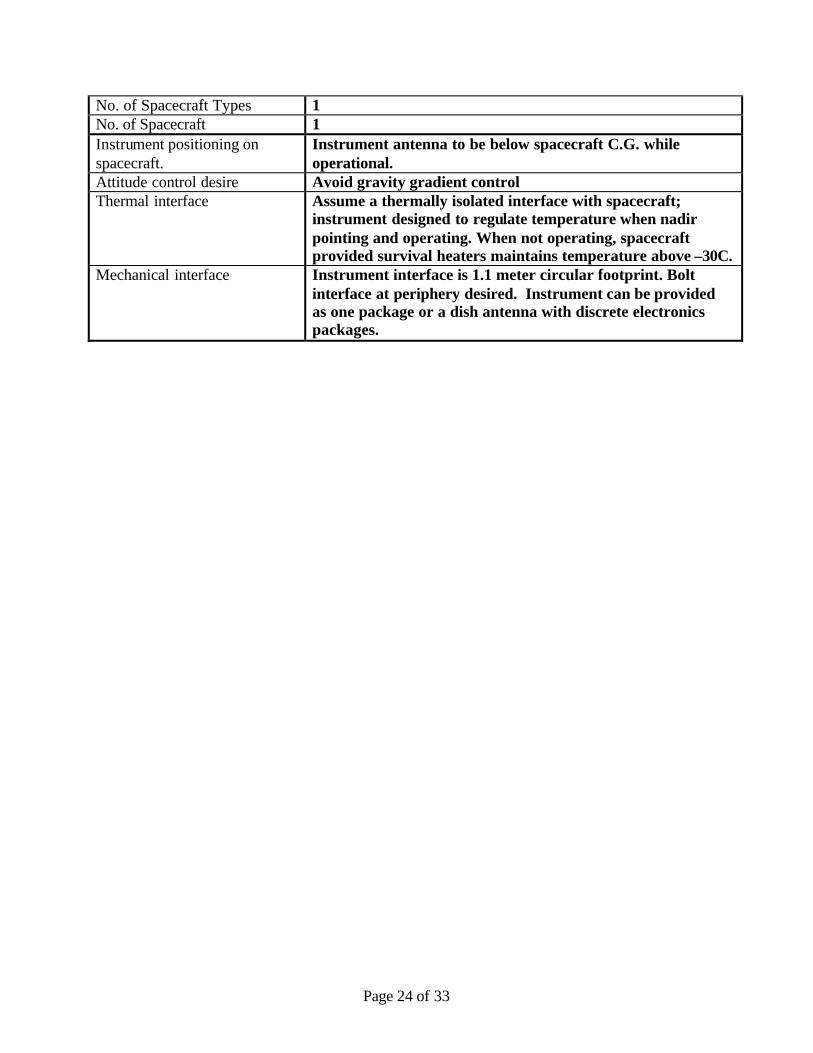
No. of Spacecraft Types 1 No. of Spacecraft 1 Instrument positioning on spacecraft.
Instrument antenna to be below spacecraft C.G. while operational.
Attitude control desire Avoid gravity gradient control Thermal interface Assume a thermally isolated interface with spacecraft;
instrument designed to regulate temperature when nadir pointing and operating. When not operating, spacecraft provided survival heaters maintains temperature above –30C.
Mechanical interface Instrument interface is 1.1 meter circular footprint. Bolt interface at periphery desired. Instrument can be provided as one package or a dish antenna with discrete electronics packages.

Page 25 of 33
Appendix D – RSDO Response to Request
January 27, 2003 To: Edward Reynolds Johns Hopkins University, Applied Physics Laboratory Thank you for your inquiry. You requested a Technical Assessment of RSDO Catalog bus Applicability, and a Rough Order of Magnitude (ROM) estimate of price. We understand that the ALT-LITE mission comprises one spacecraft in a low earth orbit, carrying a single altimeter payload complement, including a fixed dish antenna. The estimate of mission requirements that you sent to us is enclosed. In the absence of detail knowledge of the instrument, we have assumed easily packaged, benign boxes, with relatively simple interfaces. RSDO has conducted an in-house Bus Applicability study, identifying at least five potential candidate buses for your mission. The results are detailed in the accompanying spreadsheet. The TRW T100, TRW T200A, and Ball BCP 600 buses appear most interesting. The Spectrum Astro SA-200B bus may also be of interest: it is identified as having only a 1 year life capability, but we have included their option to incorporate full redundancy. The Orbital MicroStar bus may also be of interest, although the suitability of its configuration for your payload mission requires deeper study. The Applicability spreadsheet lists your estimated performance requirements and shows the corresponding performance parameters of the buses. Color-coding identifies the following:
• Green Meets requirement • Light Green Meets requirement with addition of contract option • Yellow Close to meeting requirement • Red Clearly does not meet requirement • Blue Overkill-- much more capability than needed.
Contract options that would be needed are identified in the spreadsheet. Other modifications that would be needed are also identified at the bottom. We have adjusted Catalog prices to include estimates for these modifications. Please note that three of the buses have fixed solar array wings. Two have single axis drives. We have not conducted an orbital analysis to determine if there are any resulting impacts relative to payload attitude restrictions.

Page 26 of 33
The anticipated ROM price range, when acquired competitively through the Rapid-II contract is expected to be $38 – 43 M, based purely on the in-house study. The Orbital MicroStar Bus may be somewhat less expensive. These prices are based upon the Rapid-II contracts Statement of Work and Terms and Conditions, including full refund or replacement in the event of spacecraft failure. More accurate ROM prices can be obtained only if RSDO contacts the Vendors with a more detailed Request for Information (RFI). If you would like to pursue an RFI, we will arrange additional time working with you to develop further the mission requirements information. Rapid Spacecraft Acquisition contracts are performance based, fixed price contracts that baseline utilizing Vendors’ practices where appropriate, although all terms and conditions can be modified to suit your needs. Please note that these prices may not be valid for contracts with other terms, conditions, or processes. These estimates are to be used for planning purposes and should not be distributed beyond APL direct employees or government civil servants, except on a need-to-know basis. For any additional information or discussion, please feel free to contact Bruce Clark, Associate Chief of RSDO, at [email protected]. 301-286-0404. Gregory F. Smith Chief, RSDO GSFC Code 473

Page 27 of 33
TRW Orbital TRW Ball Aerospace Spectrum Astro
ALT-LITE RQMTS Units T100 MicroStar T200A BCP 600 SA-200B
75 Max Avg PL Power EOL
W (EOL) 25 50 94125 w/SA normal to
sun86
34Payload Mass Limit of Bus
kg 36 68 75 90 100
250 wet massBus Dry Mass
(w/o PL)kg 184.1 58.6 242.4 203 90
25 science gen, 400 downlink
Science Data Downlink Capability
kbps 200 2000 140017,000
(two channels)2500
5000Science Data
Storage Capability Mbit 16.7 3 2000 2000 2000
900 Pointing Knowldg arcsec 694 2880 360 - R/P, 324 - Y 12 (3sigma); 17 yaw 317
1800 Pointing Control arcsec 833 R/P, 2777 Y 2160 1080 - R/P, 1440 - Y 13 (3sigma); 17 yaw 360
No Requirement Pointing Stability (Jitter)
arcsec/sec Unknown 36 18 arcsecs per 0.1 sec above 3 Hz
< 4.2 (3sigma) 360
Slew rate deg / min 300 60 120 ~ 60 240
5 Miss. Design Life years 3 3 4 6 1 @ .76
Pegasus XL Compatible LVs names Standard Pegasus Pegasus, Taurus Athena 1Pegasus XL, Taurus
multiple manifestMino, Peg, Taur, Ath,
Del, T-II, Atlas800 km, 60 deg
inclination Nominal Orbit 750 circular sun-synch 580 km, 97.75 deg 600 circular600 km
60 deg inclin 555 km, 28.5 deg
Types of Orbits available N / A
LEO: All inclinations, 580 - 1000 km
LEO 250 - 1000 km, any inclination
450 to 900 km, 0 deg to sun synch
All LEO sun synch, mod PL duty cycle
External Volume available for PL
6.114 cubic feet atop bus structure 1.5 m dia x 1 m h
80" diameter to LV fairing, 12.7 ft^3
111 dia taper to 70 dia at height of 101 (cm) .71 x .38 x 1.20 m
Internal Volume available for PL N/A
Special (additional PL rings as needed) N/A
71 cm x 71 cm x 55 cm high
Slots for up to 7 6U VME cards
Earth Pointing ACS type Pitch-momentum bias 3 Axis zero momentumPitch mom-biased 3
axis3 axis, zero net
momentum3 axis zero bias, wheels, mag tqs
YES GPS $ receivers 1 1, intl redund Option #3Batteries type / Ah NiCd / 9 NiH2 / 10 Super NiCd / 21 NiH2 CPV / 20 NiCd / 4 Ah (3)
Arrays cell type, area
5796 N-on-P Si, 3.75 sq. m.
Single junction GaAs, 1.57 m^2
Si 1710 x 2 / 2 wings, total 5.71 m^2
GaAs / Ge dual-j, 2.35 m^2
Si, 2.54 m^2
28 VDC Nominal Voltage V 28 14, 5, 28 28 28 28C&DH Bus Architecture description
80C86 bus central processor RS-422 distributed
1553 + 80C86 bus, central processor
HLDC, LLDC, 1553, serial digital RS422, 1553
Downlink Formats STDN STDN, CCSDS NASA/STDN & ESA CCSDS STDN CCSDS
S or X-Band Downlink Band S-Band S-Band S-Band S-Band S-Band
Structure description Hexagon / AluminumDual faced cyl,
AlBeMet/Al h'comb Hexagon / AluminumRectangular, Al h'comb
w/graph face sheets Rectangular, Al h'comb
Yes Propulsion typeMonoprop, Blowdn,
N2H4 NoneMonoprop, Blowdn,
N2H4 None None
Propellant Capacity kg 73 None 73 None None
25 Max delta v m / s 548 None 352 None None
Heritage mission name(s) TOMS-EP BATSAT, ORBCOMM ROCSAT GEOSAT follow-on MightySat II.1
nominal schedule months 18 22 21 32 37
OPTION 1 Remove PropulsionCustom struc ring for
flexible PL accomFine Pointing Battery Bypass Full Redundancy
OPTION 2Increase power up to
270 wMonoprop 28.4 kg
N2H4High data: 80 M down,
32 G storage
OPTION 3 Add 1553/1773 PL data interface
GPS (1)
OPTION 4Enhanced data storage
256 MbGround segment
integration support
OPTION 5Add propulsion
module
OPTION 6 Reduced pointing accuracy
OPTION 7 Operations for 2 yearsOPTION 8 Delete SW maintain
Rapid-II Summary

Page 28 of 33
Appendix E – Master Equipment List for Minimum Baseline Configuration
Abyss Lite - Base model 3/10/2003
QtyMass (kg)
Growth Allowance (reserves)
Total Mass not to
exceed
Ave. Power (watts) Notes
Abyss Lite 27.30 20% 32.76 50.00
RF 4.00 28% 5.20 0.00 Transceiver 1 0.00 20% 0.00 0.00 Mass and power covered in IEM S-Band omni antenna 2 1.00 30% 1.30 0.00 Hemispherical low can antennas Combiner/Diplexer/Xfer Switch Assy 1 2.00 30% 2.60 0.00 Plate mounted components Cabling 1 1.00 30% 1.30 0.00 Cabling from IEM to antennas
G&C 16.56 14% 20.03 22.00 Star tracker redundant DPU 1 0.86 10% 0.94 4.00 DTU Redundant microASC Star tracker inner baffles 3 0.21 10% 0.23 0.00 CONTOUR actuals Star tracker outer baffles 3 1.50 10% 1.65 0.00 CONTOUR actuals Star tracker heads & cables 3 0.93 10% 1.02 0.00 CONTOUR actuals Magnetic Torque rods 3 5.10 30% 6.63 6.00 Ithaco Model TR60CFR Pitch wheel 1 2.55 10% 2.81 5.00 Type-A Ithaco wheel Wheel electronics 1 0.91 10% 1.00 1.00 Ithaco data sheet Magnetometer 1 0.50 10% 0.55 1.00 EO-1 TAM mass, Used for momentum dumping GPS 1 4.00 30% 5.20 5.00 EO-1 mass. Includes antennas
Power 47.40 27% 58.82 12.00 Solar Array - Body mounted cells 6 5.40 30% 7.02 0.00 cells on all six walls.
Deployed panels (six petals) 6 9.00 30% 11.70 0.00CONTOUR panel density of 3 kg/m2. Assumes 0.5 m by 1 meter area per panel.
Battery 1 14.00 10% 15.40 0.00 12 A-H (30% max orbital DOD) PSE/PDU 1 12.00 30% 15.60 12.00 Partially redundant, one box; DET system Shunt Panel 1 1.00 30% 1.30 0.00 S/A launch restraint&hinges 1 6.00 30% 7.80 0.00 1 kg/panel for hardware
C&DH 9.15 18% 10.53 33.50 IEM 1 9.00 15% 10.35 33.50 Nine card IEM. Duty cycled transmitter TRIO (Temperture Units) 3 0.15 20% 0.18 45 Temperature readings
Bus Structure 1 22.56 30% 29.33Note that a 1 inch honeycomb deck is included in the instrument allocation
Thermal 1 7.00 30% 9.10 20.00 MLI, heaters, thermisters
Harness 1 9.23 30% 12.00 2.06 6.5% of mass + 30 percent growthReserve Power 20.00SC Total 143.20 177.77 159.56
Launch Mass 250.00Pegasus XL to 800 km; Incl=60 degrees.
Mass Margin- Dry 29% This is in addition to growth

Page 29 of 33
Appendix F – More Agile Single String System
Single String - Enhanced Capability 3/7/2003
Qty Mass (kg)
Growth Allowance (reserves)
Total Mass not to
exceed
Ave. Power (watts) Notes
Abyss-Lite 27.30 20% 32.76 50.00
RF 4.00 28% 5.20 0.00
Transceiver 1 0.00 20% 0.00 0.00Mass and power covered in IEM S-Band omni antenna 2 1.00 30% 1.30 0.00Hemispherical low can antennas Combiner/Diplexer/Xfer Switch Assy 1 2.00 30% 2.60 0.00Plate mounted components Cabling 1 1.00 30% 1.30 0.00Cabling from IEM to antennas
G&C 27.38 15% 32.26 54.00
Star tracker redundant DPU 1 0.86 10% 0.94 4.00DTU Redundant microASC Star tracker inner baffles 3 0.21 10% 0.23 0.00CONTOUR Actual Star tracker outer baffles 3 1.50 10% 1.65 0.00CONTOUR Actual Star tracker heads & cables 3 0.93 10% 1.02 0.00CONTOUR Actual
Magnetic Torque rods 3 3.00 30% 3.90 6.00Ithaco Model TR30CFR, momentum dump only
Reaction wheels 3 7.65 10% 8.42 15.00Type-A Ithaco wheel Wheel electronics 3 2.73 10% 3.00 3.00NEAR heritage Magnetometer 1 0.50 10% 0.55 1.00EO-1 TAM mass IRU 1 4.50 20% 5.40 20.00Honeywell (Clearwater) RLG
GPS 1 5.50 30% 7.15 5.00EO-1 mass, includes GPS antennas cabling
Power 46.40 27% 57.12 12.00
Solar Array - Body mounted cells 6 5.40 30% 7.02 0.00cells on all six walls.
Deployed panels (six petals) 6 9.00 30% 11.70 0.00Assumes 0.5 m by 1 meter area per panel.
Battery 1 16.00 10% 17.60 0.00Minimum of 14 A-H NiH
PSE/PDU 1 12.00 30% 15.60 12.00Partially redundant, one box; DET system
Shunt Panel 1 1.00 30% 1.30 0.00 S/A launch restraint&hinges 1 3.00 30% 3.90 0.00Placeholder. Need stiff s/a
C&DH 9.15 18% 10.53 45.00 IEM 1 9.00 15% 10.35 45.00Nine card IEM
TRIO (Temperture Units) 3 0.15 20% 0.18 45 Temperature readings
Bus Structure 1 27.20 30% 35.36 Note that a 1 inch honeycomb deck is included in the instrument allocation
Thermal 1 7.00 30% 9.10 20.00MLI, heaters, thermisters
Harness 1 10.99 30% 14.28 2.726.5% of mass + 30 percent growth Reserve Power 20.00
Spacecraft Totals 159.41 196.62 203.72
Launch Mass 250.00 Pegasus XL to 800 km; Incl=60 degrees.
Mass Margin- Dry 21% This is in addition to growth Unallocated Reserves 53.38

Page 30 of 33
Appendix G – Added Propulsion System
Abyss Lite - OnBoard Propulsion 3/10/2003
QtyMass (kg)
Growth Allowance (reserves)
Total Mass not to
exceed
Ave. Power (watts) Notes
Abyss Lite 27.30 20% 32.76 50.00
RF 4.00 28% 5.20 0.00 Transceiver 1 0.00 20% 0.00 0.00 Mass and power covered in IEM
S-Band omni antenna 2 1.00 30% 1.30 0.00 Hemispherical low can antennas
Combiner/Diplexer/Xfer Switch Assy 1 2.00 30% 2.60 0.00 Plate mounted components
Cabling 1 1.00 30% 1.30 0.00 Cabling from IEM to antennas
G&C 42.38 16% 51.76 54.00 Star tracker redundant DPU 1 0.86 10% 0.94 4.00 DTU Redundant microASC
Star tracker inner baffles 3 0.21 10% 0.23 0.00 CONTOUR Actual
Star tracker outer baffles 3 1.50 10% 1.65 0.00 CONTOUR Actual
Star tracker heads & cables 3 0.93 10% 1.02 0.00 CONTOUR Actual
Magnetic Torque rods 3 3.00 30% 3.90 6.00 Ithaco Model TR30CFR, momentum dump only
Reaction wheels 3 7.65 10% 8.42 15.00 Type-A Ithaco wheel
Wheel electronics 3 2.73 10% 3.00 3.00 NEAR heritage
Magnetometer 1 0.50 10% 0.55 1.00 EO-1 TAM mass
IRU 1 4.50 20% 5.40 20.00 Honeywell (Clearwater) RLG
GPS 1 5.50 30% 7.15 5.00 EO-1 mass, includes GPS antennas cabling
Propulsion (hydrazine based) 1 15.00 30% 19.50 0.00 Estimate based on other bus designs.
Power 51.40 27% 63.22 12.00 Solar Array - Body mounted cells 6 5.40 30% 7.02 0.00 cells on all six walls.
Deployed panels (six petals) 6 9.00 30% 11.70 0.00 Assumes 0.5 m by 1 meter area per panel.
Battery 1 18.00 10% 19.80 0.00 Minimum of 15.6 A-H NiH
PSE/PDU 1 15.00 30% 19.50 12.00 Partially redundant, one box; DET system
Shunt Panel 1 1.00 30% 1.30 0.00 S/A launch restraint&hinges 1 3.00 30% 3.90 0.00 Placeholder. Need stiff s/a
C&DH 9.15 18% 10.53 33.50 IEM 1 9.00 15% 10.35 33.50 Nine card IEM
TRIO (Temperture Units) 3 0.15 20% 0.18 45 Temperature readings
Bus Structure 1 30.24 30% 39.31Note that a 1 inch honeycomb deck is included in the instrument allocation
Thermal 1 11.00 30% 14.30 40.00 MLI, heaters, thermisters
Harness 1 12.29 30% 15.97 2.84 6.5% of mass + 30 percent growth
Reserve Power 20.00Spacecraft Totals 187.75 233.06 212.34
Launch Mass 250.00Pegasus XL to 800 km; Incl=60 degrees.
Mass Margin- Dry 7% This is in addition to growthUnallocated Reserves 16.94 Used for fuel

Page 31 of 33
Appendix H – Enhanced Redundancy
Abyss Lite - Higher Redundancy 3/10/2003
QtyMass (kg)
Growth Allowance (reserves)
Total Mass not to
exceed
Ave. Power (watts) Notes
Abyss Lite 27.30 20% 32.76 50.00
RF 5.00 28% 6.50 0.00 Transceiver 1 0.00 20% 0.00 0.00 Mass and power covered in IEM
S-Band omni antenna 2 1.00 30% 1.30 0.00 Hemispherical low can antennas
Combiner/Diplexer/Xfer Switch Assy 1 3.00 30% 3.90 0.00 Plate mounted components
Cabling 1 1.00 30% 1.30 0.00 Cabling from IEM to antennas
G&C 54.54 16% 65.58 80.00 Star tracker redundant DPU 1 0.86 10% 0.94 4.00 DTU Redundant microASC
Star tracker inner baffles 3 0.21 10% 0.23 0.00 CONTOUR
Star tracker outer baffles 3 1.50 10% 1.65 0.00 CONTOUR
Star tracker heads & cables 3 0.93 10% 1.02 0.00 CONTOUR
Magnetic Torque rods 3 1.70 30% 2.21 6.00 Ithaco Model TR30CFR, momentum dump only
Reaction wheels 4 10.20 10% 11.22 20.00 Type-A Ithaco wheel
Wheel electronics 4 3.64 10% 4.00 4.00 NEAR heritage
IRU 2 9.00 10% 9.90 20.00 Honeywell (Clearwater) RLG
Magnetometer 1 0.50 20% 0.60 1.00 EO-1 TAM mass
GPS 2 11.00 30% 14.30 20.00 EO-1 mass
Propulsion 1 15.00 30% 19.50 5.00
Power 53.40 27% 65.42 12.00 Solar Array - Body mounted cells 6 5.40 30% 7.02 0.00 cells on all six walls.
Deployed panels (six petals) 6 9.00 30% 11.70 0.00 Assumes 0.5 m by 1 meter area per panel.
Battery 1 20.00 10% 22.00 0.00 Minimum of 17.8 A-H NiH
PSE/PDU 1 15.00 30% 19.50 12.00 Partially redundant, one box; DET system
Shunt Panel 1 1.00 30% 1.30 0.00 S/A launch restraint&hinges 1 3.00 30% 3.90 0.00 Placeholder. Need stiff s/a
C&DH 16.31 18% 18.77 38.50 IEM 2 16.00 15% 18.40 38.50 Redundant 8-card IEM
TRIO (Temperture Units) 6 0.31 20% 0.37 45 Temperature readings
Bus Structure 1 32.00 30% 41.60Note that a 1 inch honeycomb deck is included in the instrument allocation
Thermal 1 11.00 30% 14.30 40.00 MLI, heaters, thermisters
Harness 1 13.00 30% 16.90 3.31 8% of mass.
Reserve Power 20.00SC Total Mass 212.54 261.83 243.81
Launch Mass 250.00Pegasus XL to 800 km; Incl=60 degrees.
Mass Margin- Dry -5% This is in addition to growthUnallocated Reserves -11.83

Page 32 of 33
Appendix I - Recommended Configuration.
Note: This configuration does not have a propulsion system in its mass rollup. In the feasibility study (Phase A), the design would be tightened up to see in a propulsion system could be implemented with mass currently allocated to the ‘growth allowance’. The system mass margin would still remain a >13%.
Abyss Lite - Recommended Long Life Configuration 3/10/2003
QtyMass (kg)
Growth Allowance (reserves)
Total Mass not to
exceed
Ave. Power (watts) Notes
Abyss Lite 27.30 20% 32.76 50.00
RF 5.00 28% 6.50 0.00 Transceiver 1 0.00 20% 0.00 0.00 Mass and power covered in IEM
S-Band omni antenna 2 1.00 30% 1.30 0.00 Hemispherical low can antennas
Combiner/Diplexer/Xfer Switch Assy 1 3.00 30% 3.90 0.00 Plate mounted components
Cabling 1 1.00 30% 1.30 0.00 Cabling from IEM to antennas
G&C 30.54 16% 36.18 40.00 Star tracker redundant DPU 1 0.86 10% 0.94 4.00 DTU Redundant microASC
Star tracker inner baffles 3 0.21 10% 0.23 0.00 CONTOUR Actual
Star tracker outer baffles 3 1.50 10% 1.65 0.00 CONTOUR Actual
Star tracker heads & cables 3 0.93 10% 1.02 0.00 CONTOUR Actual
Magnetic Torque rods 3 1.70 30% 2.21 6.00 Ithaco Model TR30CFR, momentum dump only
Reaction wheels 4 10.20 10% 11.22 20.00 Type-A Ithaco wheel
Wheel electronics 4 3.64 10% 4.00 4.00 NEAR heritage
Magnetometer 1 0.50 20% 0.60 1.00 EO-1 TAM mass
GPS 2 11.00 30% 14.30 5.00 EO-1 mass, includes GPS antennas cabling
Power 49.40 27% 61.02 12.00 Solar Array - Body mounted cells 6 5.40 30% 7.02 0.00 cells on all six walls.
Deployed panels (six petals) 6 9.00 30% 11.70 0.00 Assumes 0.5 m by 1 meter area per panel.
Battery 1 16.00 10% 17.60 0.00 Minimum of 15 A-H NiH
PSE/PDU 1 15.00 30% 19.50 12.00 Partially redundant, one box; DET system
Shunt Panel 1 1.00 30% 1.30 0.00 S/A launch restraint&hinges 1 3.00 30% 3.90 0.00 Placeholder. Need stiff s/a
C&DH 14.31 18% 16.47 38.50 IEM 2 14.00 15% 16.10 38.50 Redundant 8-card IEM
TRIO (Temperture Units) 6 0.31 20% 0.37 45 Temperature readings
Bus Structure 1 27.68 30% 35.98Note that a 1 inch honeycomb deck is included in the instrument allocation
Thermal 1 11.00 30% 14.30 40.00 MLI, heaters, thermisters
Harness 1 11.25 30% 14.62 2.71 8% of mass.
Reserve Power 20.00Spacecraft Totals 176.47 217.83 203.21
Launch Mass 250.00Pegasus XL to 800 km; Incl=60 degrees.
Mass Margin- Dry 13% This is in addition to growthUnallocated Reserves 32.17