Free Energy Research Basics - WordPress.com Energy Research Basics or ... Coil - capacitor ... Here...
196
Free Energy Research Basics or what every FE researcher need to know Revision 1 FE R&D group http://groups.yahoo.com/neo/groups/ferd041/info 2014
Transcript of Free Energy Research Basics - WordPress.com Energy Research Basics or ... Coil - capacitor ... Here...

Free Energy Research Basics
or
what every FE researcher need to know
Revision 1
FE R&D group http://groups.yahoo.com/neo/groups/ferd041/info
2014

2
Chapter 1. Power measurements ................................................................................................................ 4
Hello, ...................................................................................................................................................... 4 Magic Box #1 ......................................................................................................................................... 6 Light bulbs..............................................................................................................................................8 Measuring power in AC circuits .......................................................................................................... 11 Magic Box #2 ....................................................................................................................................... 13
Chapter 2. Flyback ................................................................................................................................... 16 Flyback circuit...................................................................................................................................... 19 Looping flyback ................................................................................................................................... 20 Trying harder….................................................................................................................................... 23 Simulating flyback ............................................................................................................................... 25 Magic Box #3 ....................................................................................................................................... 27 Joule Thief and LED lights .................................................................................................................. 31 Observing core saturation..................................................................................................................... 36 Simulation with “real” core and “real” diode....................................................................................... 37 B-H curve model .................................................................................................................................. 39 Plotting BH curves yourself ................................................................................................................. 43 HV power source.................................................................................................................................. 46
Chapter 3. Resonance............................................................................................................................... 49 Parallel and series resonance circuits ................................................................................................... 49 Single switch driver.............................................................................................................................. 51 Push pull driver .................................................................................................................................... 53 Half bridge driver ................................................................................................................................. 56 Bridge drivers ....................................................................................................................................... 57 Analogue approach............................................................................................................................... 62 Extracting power .................................................................................................................................. 64 More examples of power extracting circuits ........................................................................................ 67 Ferroresonance ..................................................................................................................................... 72 Properties of ferroresonance................................................................................................................. 77 Tesla switch and Co. ............................................................................................................................ 82 Switching coils and caps ...................................................................................................................... 83 Simulating switched capacitors ............................................................................................................ 87 Switching coils and caps ...................................................................................................................... 90 Variable Inductor.................................................................................................................................. 93 Magnetic amplifiers.............................................................................................................................. 98 Parametric resonance.......................................................................................................................... 103 Building parametric resonator ............................................................................................................ 106 Standing waves or resonance in a media............................................................................................ 109 Waves in ferrite core .......................................................................................................................... 111
Chapter 4. Bifilar coils ........................................................................................................................... 113 Permanent magnets ............................................................................................................................ 113 Magnetic field of a”regular” coil ....................................................................................................... 117 Simple magnetic field probe............................................................................................................... 119 Magnetic field of bifilar coil .............................................................................................................. 120 Magnetic field of bifilar coil 2 ........................................................................................................... 124 Opposite coils on ferrite rod............................................................................................................... 128 Opposite coils on the ring core........................................................................................................... 131 Reversed Phi transformer ................................................................................................................... 135 Scalar coil ........................................................................................................................................... 137
Chapter 5. Displacement current ............................................................................................................ 145

3
How they do that? .............................................................................................................................. 145 Coaxial transformer with a «pipe»..................................................................................................... 150 Properties of coaxial transformer ....................................................................................................... 152 Displacement current in capacitor...................................................................................................... 155 Capacitor with a coil on ring core ...................................................................................................... 159 Capacitor with a coil of ferrite rod ..................................................................................................... 162 Coil - capacitor ................................................................................................................................... 167 Aligned and anti-aligned connection.................................................................................................. 170 Coil-capacitor on the ring core........................................................................................................... 173
Chapter 6. Negative resistance ............................................................................................................... 175 Examples of NDR with transistors..................................................................................................... 179 Zener diode......................................................................................................................................... 181 Core saturation ................................................................................................................................... 182 LC circuit as negative resistance........................................................................................................ 184 Avalanche breakdown effect in transistor .......................................................................................... 187 Broomstick antenna............................................................................................................................ 189 Spark gap............................................................................................................................................ 190 Shorting .............................................................................................................................................. 192
Afterword ............................................................................................................................................... 194 Software .................................................................................................................................................195

4
Chapter 1. Power measurements
Hello ,
I am starting a series of posts about FE research b asics. As a start topic, let’s consider some typical mista kes when power measurements performed. Here an example of message from overunity.com (it i s from 2007 but you still can occasionally re-posted by somebody).

5
Another similar device, looks like Bedini’s Tesla s witch.
Here a photo of working device ☺

6
In other words, author said “Hey, I have one bulb i n series with power supply and one on the output of my magic box. See, first lamp is just glowing, and second one is shining bright. I got OU !” I am sure that everyone has seen such claims made b y different people with different devices many many times.
Magic Box #1 Let's take a look inside a "magic box" ;-) To simplify simulation I am using alternative curre nt and... just an regular step-down transformer (1:10) as a "magic box" ;-) I am also using resistors instead of light bulbs.
pic. Magic Box design
7
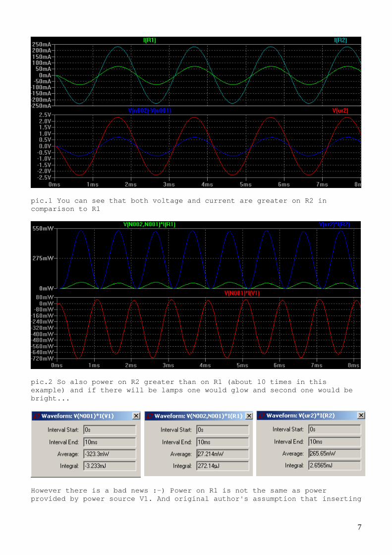
pic.1 You can see that both voltage and current are greater on R2 in comparison to R1
pic.2 So also power on R2 greater than on R1 (about 10 times in this example) and if there will be lamps one would glow and second one would be bright...
However there is a bad news :-) Power on R1 is not the same as power provided by power source V1. And original author's assumption that inserting
8
a light bulb in series with device could help compa ring input vs. output power is obviously wrong. As it was expected in this setup all power comes fr om V1 and it is equal to sum of power on R1 and R2 (not taking into account loses in the transformer). I let you as an "exercise" to design a "magic box" which works similar way but with direct current :-)
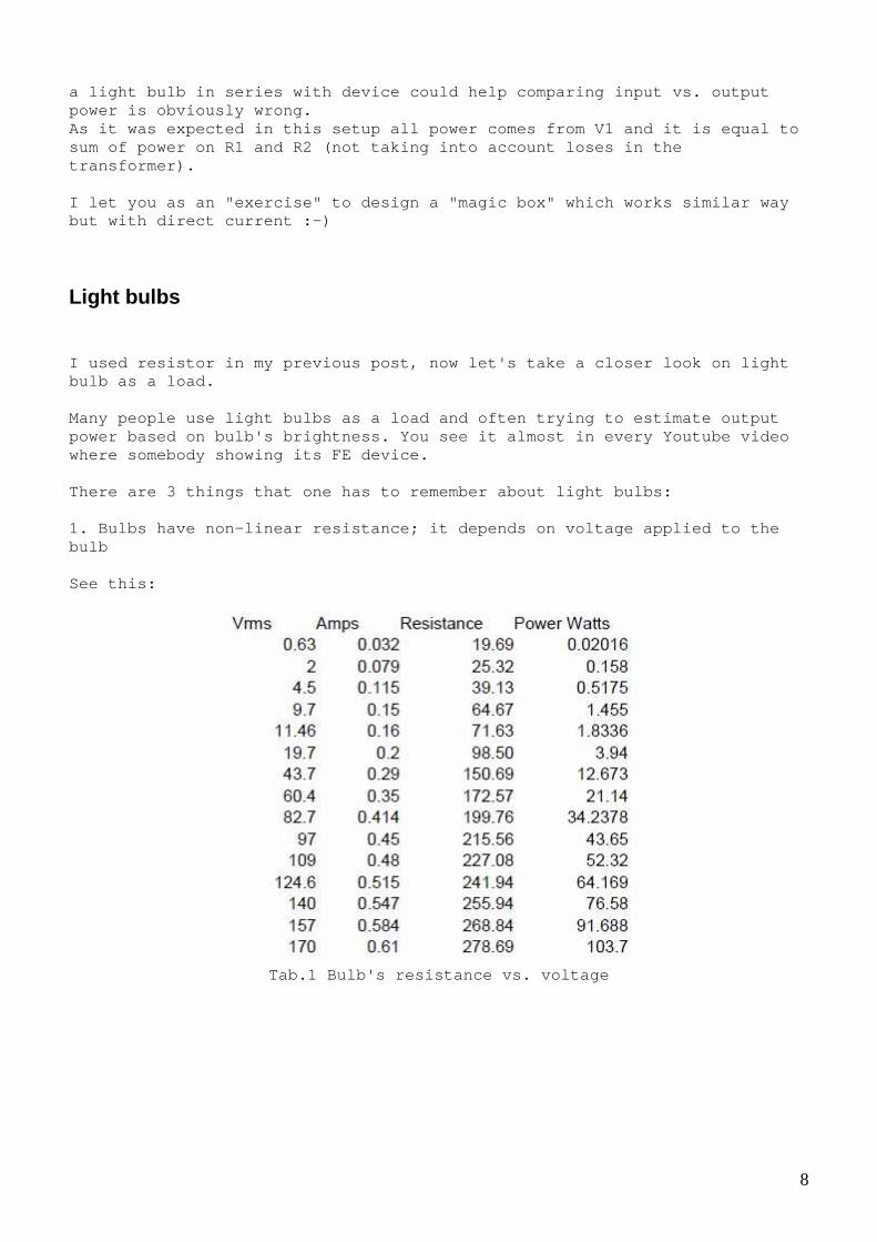
Light bulbs I used resistor in my previous post, now let's take a closer look on light bulb as a load. Many people use light bulbs as a load and often try ing to estimate output power based on bulb's brightness. You see it almost in every Youtube video where somebody showing its FE device. There are 3 things that one has to remember about l ight bulbs: 1. Bulbs have non-linear resistance; it depends on voltage applied to the bulb See this:
Tab.1 Bulb's resistance vs. voltage

9
pic. 1 Bulb's resistance vs. voltage
and this
pic.2a Bulb's current vs. voltage

10
pic2b. Power vs. voltage
(original document can be found here http://site.devicecraft.com/ApplicationNotes/60_wat t_Incandescent_Bulb_Characteristics.pdf ) 2. Bulb's brightness also non-linearly depends on v oltage (and frequency) and it also changing with the lamp's age. See this < http://www.photometrictesting.co.uk/File/lamp_depre ciation.php > 3. Bulbs have "inertia". This means that it takes m illiseconds or seconds until current thru the lamp became stable when cons tant voltage applied. All these properties make accurate power estimation based on light bulb's brightness very difficult. Gustavo mentioned that bulb can be used as a curren t limiter. It's a quite common application but one always has to remember a bout bulbs "inertia". Many sensitive circuits can blow up completely whil e lamp is warming up :-) P.S. Perhaps it would be interesting to make experi ment and study bulb's nonlinearities.

11
Measuring power in AC circuits Another interesting topic is Measuring power in AC circuits. Let's consider a practical example. You have some circuit, it produce some power on the output. You put a load resistor and observing voltage on it with oscillosc ope. Here example picture (from my TV research)
pic.1 Sample waveform
Let's assume that load is 10 ohm resistor and peak- to-peak voltage on it 5.28v (channel one on the picture) What is an output power here? Let's use Ohm's law and calculate ;-) I = U / R P = U * I = U 2 / R = 5.28 * 5.28 / 10 = 2.78 W Ok, did you get OU? Ha, ha, perhaps :-) After thinking a while you remember that it was act ually peak-to-peak voltage... so to get number comparable with DC you have to divide result by 2.... Oh no! Actually by 4 (because there is U * U in the formula)

12
So it will be P = 2.78 / 4 = 0.69 W (is it still OU ? ;-) After thinking one more moment, you probably rememb er that you also have to use RMS coefficient, so... again divide by two squa re root of 2, or
P = 0.69 / / = 0.34 W (what a disappointment! :-) And if we collect everything in one formula we get P = Upk * Upk / R / 8.
This coefficient ( ) depends on signal shape. Here some reading about RMS https://en.wikipedia.org/wiki/Root_mean_square and an example simulation to consider
pic. Comparison of power in DC and AC

13
Magic Box #2 And last thing I can't leave without our attention in this thread - yet another "magic box" case :-) a.k.a. Power consumption drop under load. Have you ever met a person who claims: "Hey guys, I made amazing device. When I put load on it actual power consumption is d ropped. This is a straight way to over unity!" He, he... I have met many... So let's consider another magic box (version 2)
pic.1 Magic Box #2 concept
In first case (top picture), power source is drivin g only the Magic Box. When we attach some load (bottom picture), amazingl y, power consumption decreases even some power goes into load. Ok, can we make such "magic box"? Sure, we can :-) Here my design. I am again being lazy and do it for AC, you can build DC version yourself.

14
pic.2 Magic box design and simulation

15
pic.3 Power measurements
After all, do you think it was "wrong way"? ;-)
16
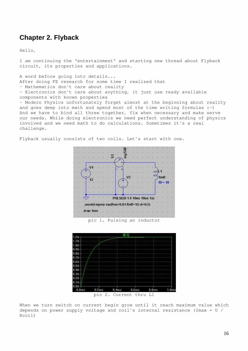
Chapter 2. Flyback Hello, I am continuing the "entertainment" and starting ne w thread about Flyback circuit, its properties and applications. A word before going into details... After doing FE research for some time I realized th at - Mathematics don't care about reality - Electronics don't care about anything, it just us e ready available components with known properties - Modern Physics unfortunately forget almost at the beginning about reality and goes deep into math and spend most of the time writing formulas :-) And we have to bind all three together, fix when ne cessary and make serve our needs. While doing electronics we need perfect understanding of physics involved and we need math to do calculations. Somet imes it's a real challenge. Flyback usually consists of two coils. Let’s start with one.
pic 1. Pulsing an inductor
pic 2. Current thru L1
When we turn switch on current begin grow until it reach maximum value which depends on power supply voltage and coil’s internal resistance (Imax = U / Rcoil)

17
This “grow” is exponential as it shown on pic.2, ho wever in practice usually we will be using only very beginning of the process so current grow will be almost linear (see region t < 0.1ms). It is often said that current thru coil can’t chang e “fast” or “momentary”. This is not exactly true as we will see soon. While current grows magnetic field also “building up” and some energy being “sto red” in magnetic field across the coil (E = L * I * I / 2) If we disconnect coil from power source, current th ru coil stops abruptly, so magnet field collapse and big voltage spike appe ars across the coil (if no load connected).
pic.3 Switching off
This process can be seen on pic.3, “size” of voltag e spike across the coil depends on coils parameters (capacitance, internal resistance etc.)

18
pic.4 Same process observed in real schematic with oscilloscope
pic5. Here an example schematic which can be used f or this experiment
And here some links with info to consider: http://www.electronics-tutorials.ws/electromagnetis m/magnetism.html http://hyperphysics.phy-astr.gsu.edu/hbase/electric /indsol.html

19
Flyback circuit As we saw in previous post, when we disconnect powe r supply energy stored in magnetic fields "disappears" (from our circuit). Th is is not very good, so let's add another coil and "capture" this energy ba ck :-)
pic.1 This a typical Flyback setup.
Diode in the secondary needed to prevent current th ru the load during first working phase when energy “stored” into magnetic fi eld. In the second phase, collapsing magnetic field creates voltage on the se condary coil and if there is a load connected; current begins to flow (almost immediately). This current creates own magnetic field which oppose to original field. It is interesting that the lower load resistance the high er current will be in secondary and stronger field it creates, therefore the longer (wider) output pulse will be. Another interesting feature is that fly back always draws

20
same power from power supply independently what loa d applied to secondary, it also does not “afraid” of shorting output. This kind of setup used in many different variation s in nowadays power supplies. Here some interesting is reading about flyback: http://www.dos4ever.com/flyback/flyback.html http://www.ti.com/lit/ml/slup261/slup261.pdf
Looping flyback As we discussed earlier, we “put” some energy into magnetic field with primary coil and then “collect” it back with second ary coil. By some reason people tend to think that we can get out here more than we put in. Just imagine, you put some water in a cup and when you drink it appeared that there is more water than you put in. Wouldn’t it be nice to have such magic cup ☺ Ha, ha, anyway, people keep trying and I can’t resi st give it a try as well…

21
pic.1 Simulation of “looped flyback”
Notice power supply and coils current values ;-)
pic.2 Experiment’s schematic

22
pic3. Switch control pulse (A) and voltage in point (B)
pic4. Switch control pulse (A) and voltage in point (C) = current thru coil
L1 (Spikes at the beginning of the pulse caused by MOSFET gate charging process)
pic5. Switch control pulse (A) and voltage in point (D) = current thru coil
L2

23
pic6. Experimental setup (some components are not u sed in this experiment)
As simulation show, this setup consumes very small current 100uA – 5mA depends on pulse width and coils and can be used to measure loses in ferrite.
Trying harder… Somebody probably say: "You not being serious and y ou not trying hard!" Ha! ha! Being serious will not help us ☺ Here similar “Flyback looped” setup I tried earlier

24
pic1. One of the earlier trials
The issue with flybacks is diode in secondary, volt age drop on it, internal capacitance and limited turn-on time (delay). Addin g small inductor in series sometimes can help to “handle” current spike s. Decreasing capacitor connected to power gives possi bility observe how power transferred from secondary.
25
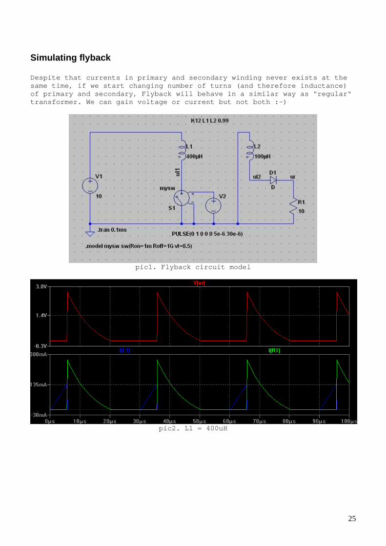
Simulating flyback Despite that currents in primary and secondary wind ing never exists at the same time, if we start changing number of turns (an d therefore inductance) of primary and secondary, Flyback will behave in a similar way as "regular" transformer. We can gain voltage or current but not both :-)
pic1. Flyback circuit model
pic2. L1 = 400uH

26
pic3. L1 = 200uH
pic4.L1 = 100uH
I made this simulation to illustrate how change off L1/L2 ratio affects output voltage and current.

27
Magic Box #3 Let’s consider another “Magic Box”. From time to time you see a video or post where som e smart guy telling that he invented very advanced schematics which allow yo u to power some load from battery and charge the battery at the same time. Wo uldn’t it be nice to have such circuit?
pic.1 Magic Box #3 concept – we attach something to the battery via current meter and… surprisingly it shows that current actua lly flowing into the battery...Does it charging the battery ? Well, this magic box creates much more controversy rather than two previous. I would like to show two similar devices behaving l ike described “magic box”, both devices are based on flyback circuit.
pic1. “Magic” LED light “charging” small NiMH batte ry

28
pic2. top – MOSFET’s drain, bottom – current thru b attery
pic3. top – MOSFET’s gate, bottom – current thru ba ttery

29
pic4. top(yellow) – MOSFET’s gate, bottom (blue) – voltage on battery
As you can see, circuit creates current pulses “int o battery” ;-)
pic5. Experimental setup
I let you decide yourself what is “wrong” with this “magic box”…

30
pic6. Another similar device
Author claims that this circuit allows power some s mall load from rechargeable battery for period about 2 years. He also said that after that time battery's electro des dissolved almost completely and he had to throw it away…

31
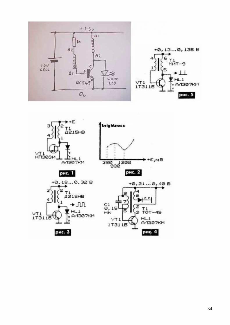
Joule Thief and LED lights I think you agree that Joule Thief is one of most p opular circuits on the web. It is not a flyback but I think it is kind of relat ed circuit and it would be interesting to mention it.
pic1. Joule Thief simulation
32
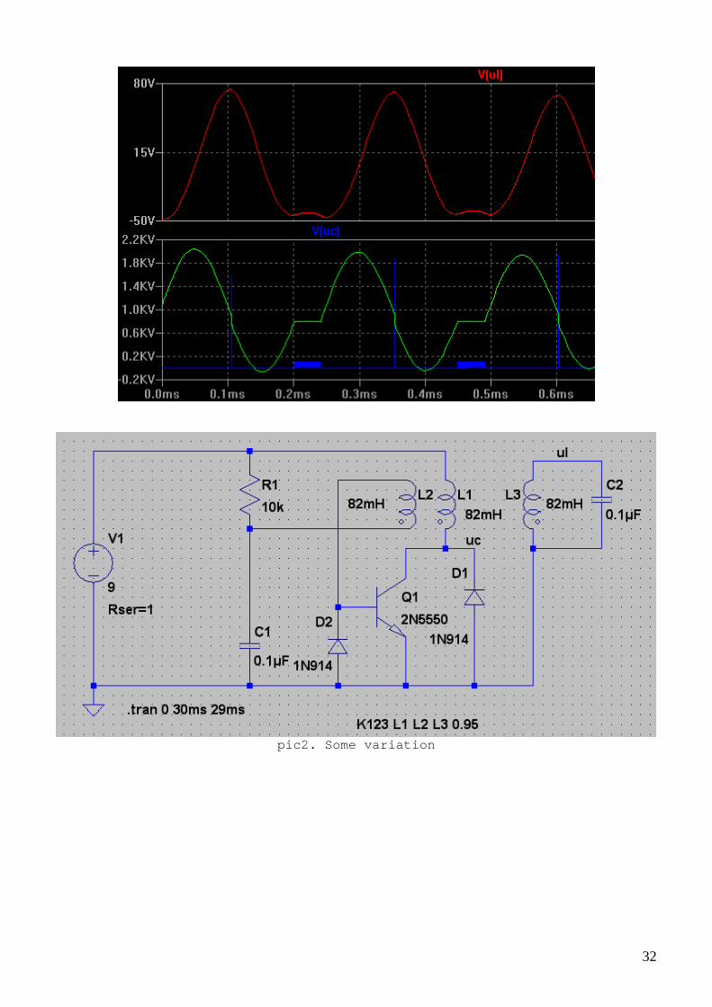
pic2. Some variation

33
pic3. MCU based flash light
pic4. Slightly modified MCU based flash light
34
35
pic5. Different JT-like circuits
pic6. My version of LED flash light, I think more p ractical ☺ Suggested reading: - SMPS http://en.wikipedia.org/wiki/Switched-mode_power_su pply - blocking oscillator http://mysite.du.edu/~etuttle/electron/elect37.htm

36
Observing core saturation
pic1. Core saturation
top – MOSFET control pulse; bottom – current in the primary coil (observed across resistor in MOSFET’s source) * Notice that after some time current start growing very fast (and non-linear)
pic2. Example circuit
This is same ”looped flyback” circuit I posted befo re.

37
To observe saturation you just need gradually incre ase pulse width and observe current thru resistor in MOSFET’s source (p oint C). When experimenting with saturation you should take care about MOSFET cooling because current grows very fast and transistor can became very hot. Transformer core saturation one of most common reas ons of low efficiency in power supply circuits. Some related links http://en.wikipedia.org/wiki/Saturation_%28magnetic %29 (Surprisingly not much information on the topic on the web)
Simulation with “real” core and “real” diode LTSpice gives some possibilities to simulate behavi our of real cores and other components like diodes. I don’t think that it is very practical but interes ting to try ☺

38
pic.1 Flyback with real core (based on LTSpice buil t-in model)
* notice shape of current in primary and secondary

39
pic2. Adding real diode to the simulation
* notice oscillations on primary So it’s looks quite similar to what real oscillosco pe shows.
B-H curve model As we saw "real" core in transformer brings non-lin earity Let's consider these effects in more details
pic.1 A page from LTSpice manual about built-in cor e model

40
pic.2 BH curves drawn with above formulas
41
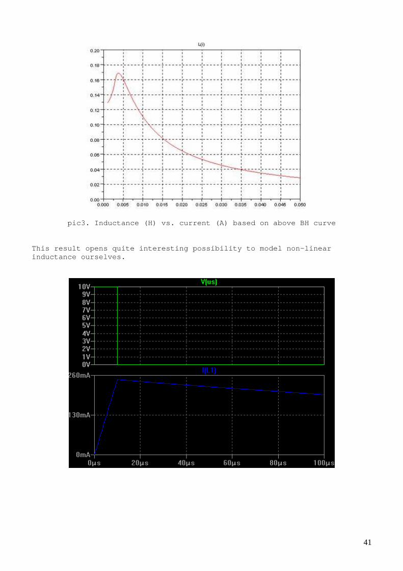
pic3. Inductance (H) vs. current (A) based on above BH curve
This result opens quite interesting possibility to model non-linear inductance ourselves.

42
pic4. Simple circuit with linear inductance
pic5. Simulation for above circuit made in SCI lab using model for non-linear core

43
Graphs from top to bottom: - voltage on power source, - current thru inductor, - voltage on inductor, - inductance of inductor vs. time * Notice current and inductance variations This simulation made using Finite difference method to solve differential equation Us = IR + L dI / dt It might be not very straight forward to perform (c omparing to LTSpice simulation) but it gives us full control on the mod el. Some links: https://www.dropbox.com/s/lx23vkvjpsgi0hc/John%20Ch an%20Nonlinear_Transformer_Model_for_Circuit_Simulation.pdf http://en.wikipedia.org/wiki/Finite_difference_meth od
Plotting BH curves yourself We saw quite a lot of theoretical staff about BH cu rve and core non-linearity. Perhaps it would be interesting to do something pra ctical about it.
pic.1 Core tracer schematic
With this simple circuit and oscilloscope we can ob serve actual magnetization curves for different cores. It is also interesting how magnet affects these cur ves.

44
pic2. Effect of magnet attached to the core's side
Here some pictures of experimentally obtained BH cu rves for Ferroxcube N30 ring core.

45
pic3. Effect of magnet inserted into core’s gap

46
pic4. BH curve for N87 ferrite from datasheet - loo ks similar to what we see in experiment ☺ Plotting Magnetization Curves http://info.ee.surrey.ac.uk/Workshop/advice/coils/B HCkt/index.html http://www.cliftonlaboratories.com/type_43_ferrite_ b-h_curve.htm
HV power source We saw a step-down flyback application in MB3, another very important application of step-up flyba ck is a spark gap drivers and HV DC power sources.

47
pic1. Schematic HV pulse generator and optional vol tage multiplier
pic2. Pulse generator and multiplier assembled in p lastic boxes

48
pic3. Side view
pic4. Testing before placing into boxes
This simple circuit produces short pulses up to 5KV (without multiplier) and capable to supply about 1ma current at 5KV with 10 stage multiplier. Output voltage can be adjusted in some range by cha nging pulse width (20k pot.). Please be careful when working with high voltage! Some related links: 10KV power source http://www.sentex.ca/~mec1995/circ/hv/hvdcgen/hvdcg en.html

49
Chapter 3. Resonance Resonance is next topic I would like to discuss. Let’s start with two most common setups –
Parallel and series resonance circuits
In these two setups energy from capacitor (C * U * U / 2) flow to inductor (L * I * I / 2) and back. “Originally” this energy comes from power supply (V1). Resonance circuit «accumulate» energy until p ower of source became equal to power of loses in the circuit. Or Pcirc = Psource * Q where Q is quality factor
pic1. Parallel resonance circuit
pic2. Simulation of parallel resonance circuit

50
In parallel resonance circuit we have circulating c urrent Q times more than power source current * notice current decreasing while oscillation settl ing down
pic3. Series resonance circuit
pic4. Simulation of series resonance circuit In series resonance circuit voltage on capacitor (a nd inductor) Q times more than voltage on power source. * notice voltage grow while oscillations settling d own We can “accumulate” some energy in resonance circui t, we can “extract” this energy back at any time and rate but…no more than w e put there from power source. By some reason people tend to believe that there is extra power in resonance circuit and we just need to find a way how to get i t from there ;-)
51
Some reading about resonance: http://www.allaboutcircuits.com/vol_2/chpt_6/1.html http://www.electronics-tutorials.ws/accircuits/seri es-resonance.html http://www.electronics-tutorials.ws/accircuits/para llel-resonance.html http://farside.ph.utexas.edu/teaching/315/Waves/nod e12.html
Single switch driver
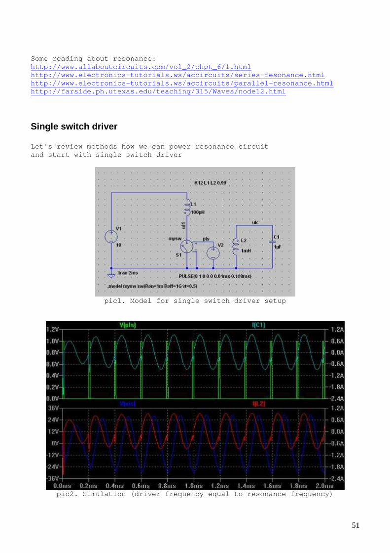
Let's review methods how we can power resonance cir cuit and start with single switch driver
pic1. Model for single switch driver setup
pic2. Simulation (driver frequency equal to resonan ce frequency)

52
pic3. Simulation (driver frequency 10 times lower t han resonance frequency)
pic4. Simple driver setup schematic
* notice diode in MOSFET’s drain to prevent built-i n zener diode to interfere
53
pic5. top – driver signal (point A), bottom – volta ge on inductor and
capacitor (point B) This circuit quite simple and can be used for exper iments on frequencies up to 100kHz. Two transistors can be replaced with int egral MOSFET driver like TC4020…4029 (or similar) For higher frequencies cd4 011 can be replaced with 74hc00 (requires 5v power supply and changes in MOS FET driver).
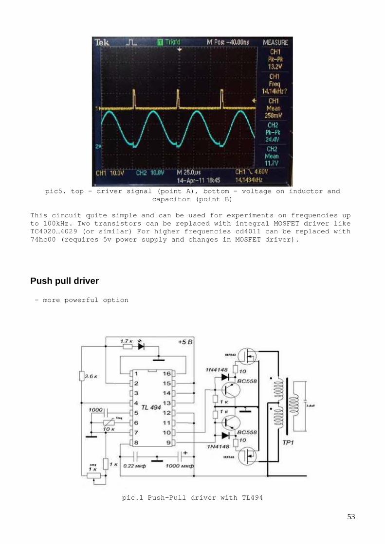
Push pull driver – more powerful option
pic.1 Push-Pull driver with TL494

54
It appeared that TL494 does not work well on low fr equencies so I made a simple substitution for it using CD4011 and CD4013. Other possibility is to use KA7500 (pin-to-pin replacement for TL494 which works ok on low frequencies) or some other PWM chip.
pic2. Push pull driver using CMOS logic
* 50k pots are mechanically connected so driver leg s adjusted synchronously ** Additional 4011 elements after 4013 needed to av oid loading 4013 outputs by RC chains (number of elements can be reduced by using 4001 elements and rearranging the circuit)

55
pic3.top - one MOSFET’s drain, bottom - secondary ( w/o capacitor)
pic4. MOSFET drains
pic5. top – one of MOSFET’s drain, bottom - seconda ry (with capacitor
connected) This circuit can also be used as an inverter to pro vide power to some appliances like led lamps etc.

56
Links: - Designing Switching Voltage Regulators With the T L494 http://www.ti.com/lit/an/slva001e/slva001e.pdf - http://www.instructables.com/id/250-to-5000-watts-P WM-DCAC-220V-Power-Inverter/
Half bridge driver
pic1. Simple half-bridge driver based on 74HC4046 V CO.
* Power supply voltage can be increased up to 35v ** Value of resistor in 2n7000 drain may be need to be changed (depends on frequency and power supply voltage)
pic2. Voltage and current in inductor
This driver works quite ok up to 200-300kHz

57
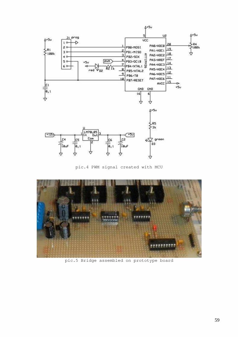
Bridge drivers Let’s review one of possible MCU controlled HBridge setup
pic.1 Regulated DC-DC converter (output voltage can be adjusted 50-200v)

58
pic.2 One half of bridge driver
pic.3 LPF filter
59
pic.4 PWM signal created with MCU
pic.5 Bridge assembled on prototype board
60
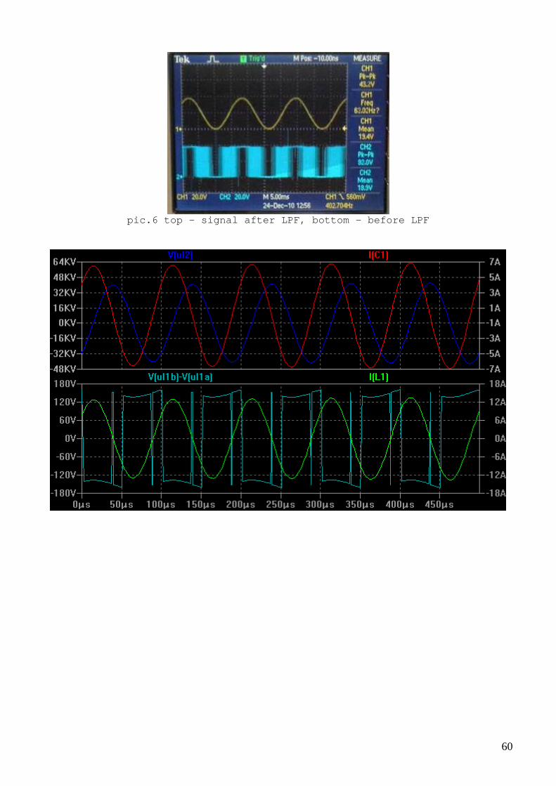
pic.6 top - signal after LPF, bottom - before LPF

61
pic.7 Simulation of HBridge
This is example of much more complicated setup. MCU s allow modify operation of the bridge without changing circuit. But it is a lso possible use “hardware” PWM like TL494 to produce PWM signal to control the bridge output. Embedded software for MCUs created using Win AVR C compiler (see attached archives). Some links: - see page 40 for more advanced version of the brid ge driver <https://04e8faec-a-62cb3a1a-s-sites.googlegroups.com/site/vasik041/homebrewtools. pdf?attachauth=ANoY7cqaamgaX-JXJRbIvErNtp4oVDipTLpw8NCUaF6guZH622pxRZFsEKfUf7rxr 6RRJziZ2sa5h1sKsMRELqgyBKtBBHR4_hlT7884j9Mb9MEAX04mO1mauadYqHKhOUHz20_Gc0i1S0ABrvvWf6yZJEgyyCKNPGUOf79k6F3Ne7oiTyuFd6xwBFDyH8mYLfxfxfelQBj_Z741wnWr98H3b Wy2nOJXpw%3D%3D&attredirects=0 > - http://www.tantratron.tk/index/tantratron.html - http://winavr.sourceforge.net/ - http://www.wpi.edu/Pubs/E-project/Available/E-proje ct-042711-190851/unrestricted/PWM_Techniques_final.pdf - http://uzzors2k.4hv.org/index.php?page=ihpll1 - http://webpages.charter.net/dawill/tmoranwms/Elec_I ndHeat1.html - https://www.fairchildsemi.com/an/AN/AN-9012.pdf

62
Analogue approach We saw variety of digital drivers, but it is also p ossible to do it in a "pure analogue" way. This is more (or less) convent ional electronics, so I will just list circuits which I tried.
pic.1 Sin wave generator
pic2. Simple sin wave generator which require with one power supply voltage

63
* Disadvantage of both generators is that FET trans istor and precise selection of components needed
pic3. Simple power amplifier
* Perhaps too simple, it has big crossover distorti on
pic4. Simple driver (circuit found as a generator f or tape recorder erase
head) * Despite simplicity it works very nice, it tunes r esonance automatically if L or C changes Links: http://sound.westhost.com/articles.htm

64
Extracting power We saw many different driver setups; all of them al low us “put” some power into resonance circuit and create some oscillations . Now let’s consider ways how we can extract power back.
pic1. We can use small additional winding on induct or
pic2. Simulation for circuit with additional windin g

65
pic3. We can take power from capacitor
pic4. Simulation for “extracting from capacitor” ci rcuit
Some people are claiming that they “just invented” new and very advanced concept of extracting power from resonance circuit. Well, for me it sounds naive. It all was invented about 100 years ago, we just got better components (e.g. diodes) but ideas are the same.

66
pic5. Crystal radio as an example of power extracti on circuit
pic6. More powerful setup
We cam use different setups, with diodes or switche s but at the end load (or extracted power) always “work” as Q factor loss in resonant circuit. (This claim easy to prove using electrical circuits theor y by drawing equivalent schematics). Links: High Power Crystal Set http://hibp.ecse.rpi.edu/~john/xtal.html http://www.crystalradio.net/crystalplans/ http://www.makearadio.com/ http://www.radiosparks.com/schematics.asp?UID=Cryst al+Radio http://en.wikipedia.org/wiki/Mihajlo_Pupin http://en.wikipedia.org/wiki/Loading_coil

67
More examples of power extracting circuits These two circuits are my implementation of Hector’ s transverter (TV) which is often discussed on EVGRAY group. It could be a nice tool to learn about resonance, d rivers and power extracting circuits… However, I see these circuits as an “over complication” in a hunt for “magic” resonance or frequency. If th ere would be a real “extra” power no such complex setup would be needed , just a regular diode bridge work fine ;-) First setup is MCU based, MCU control driver and di ode plug switches.
pic1. MCU used to control the setup

68
pic2. Other parts of the setup (driver, transformer , diode plug, zero
crossing detector and discharge switches) Below shown less complicated setup, without MCU.

69
pic3. Simple “diode plug” (two zero-crossing detect ors and triac drivers)
Here some diagrams from important points in the cir cuit
pic4. top – transformer output, bottom - voltage on positive leg capacitor

70
pic5. top – transformer output, bottom - voltage on negative leg capacitor
pic6. top – transformer output (more power injected ), bottom - voltage on
the output (Rn) I made this simulation to illustrate the idea of TV setup. Transformer core is linear in this simulation.

71
pic7. Simple TV model
72
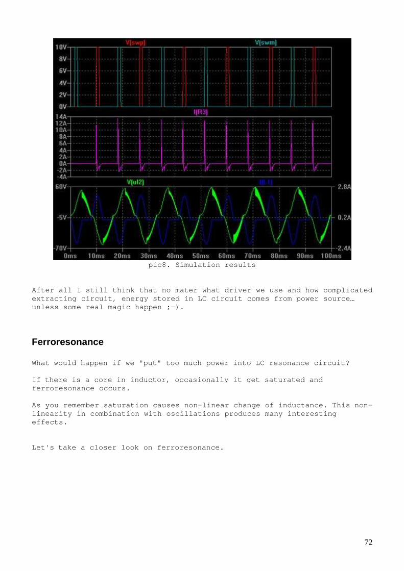
pic8. Simulation results
After all I still think that no mater what driver w e use and how complicated extracting circuit, energy stored in LC circuit com es from power source… unless some real magic happen ;-).
Ferroresonance What would happen if we "put" too much power into LC res onance circuit? If there is a core in inductor, occasionally it get sa turated and ferroresonance occurs. As you remember saturation causes non-linear change of inductance. This non-linearity in combination with oscillations produces many interesting effects. Let's take a closer look on ferroresonance.

73
pic1. Parallel ferroresonance model
pic2. Simulation of parallel ferroresonance
* notice frequency variations and current shape

74
pic3. Series ferroresonace model
pic4. Simulation of series frerroresonance
* notice voltage on the inductor Here a simple setup to observe a ferroresonance

75
I used 4,7uF capacitor and 20 turns coil on 35mm N3 0 ferrite ring, signal generator and audio amplifier as a signal source. B elow waveforms I got after tuning resonance:
pic5. Observing series ferroresonance
In simple words, when current increase core saturat ing and inductance decrease, this cause current increase even more. When studding non-linear inductance we managed to g et a formula how inductance depends on current, now we can use this to draw a resistance of LC circuit witch take into account inductance varia tions.

76
pic6. Drawing reactance (reactive resistance) for L C circuit with saturating
inductor (voltage vs. current) Formulas used to draw above graphs:
Does it look interesting? (yes, it is negative differential resistance, I am going to discuss it later in more details) Some links: http://en.wikipedia.org/wiki/Electrical_reactance http://www05.abb.com/global/scot/scot235.nsf/verity display/2e4528a2d55c5414c12572dd00247313/$file/vt%20guard_presentation-ferro res_sales_version_eng.pdf http://www.kau.edu.sa/Files/320/Researches/52676_22 982.pdf

77
Properties of ferroresonance To observe interesting properties of ferroresonance circuits I made a simple sweep generator and loaded it with parallel LC circ uit.
pic.1 VCO generator
pic.2 Driver

78
pic3. Triangle generator (I will use it as a modula tor to control VCO
frequency)
pic4. Experimental setup assembled on bread board
In first experiment I didn’t use modulation but slo wly adjusted frequency manually. I measured voltage and current on inducto r, here results
and graphs drawn based on the data

79
pic5. Voltage on inductor vs. frequency
pic5a. Inductor’s current vs. frequency
You can see interesting effect - sometimes it calle d “trigger effect”. When frequency slowly increased voltage and current also increasing until some point and then amplitude drop sharply. Frequency ne ed to be decreased significantly first to repeat this effect. Below pictures obtained with modulation generator, circuit tuned so that we can continuously observe trigger effect.

80
pic6. yellow - voltage on inductor U, blue – inductor current I, red - U * I
pic7. voltage on inductor pic8. inductor current
pic9. inductor’s current (bigger scale)
In resonance energy is «accumulated» in LC tank, bu t after some point it "does not fit" into the coil anymore because induct ance decrease due to saturation, this cause non-linear oscillations and trigger effect. I also tried to adjust power supply voltage and see how it affects oscillations. Below pictures obtained for different power supply voltage

81
pic.10 Ups=20v
pic.11 Ups=25v
pic.12 Ups=30v
The higher the power supply voltage the greater fre quency up to which the ferroresonance occurs. So in this mode of operation to achieve more current and voltage we have to “apply” more energy from pow er source (again).

82
Tesla switch and Co. We saw a "natural" non-linearity caused by saturati ton, but what if we want create non-linearity ourselves? One interesting app roach is to change inductance and capacitance in LC circuit “on-the-fl y”. Let's consider first “switching capacitors”.
pic1. Two capacitors in series and in parallel
Often people confused with capacitance, charge and stored energy when rearranging capacitors. This confusion cause some “ interesting” claims about extra energy etc. Let’s remember what we learned in school and calculate capacitance, charge and stored energy for these two cases shown on pic1. For series connection: Cs = C/2 Qs = C/2 * U = C * U / 2 Es = C/2 * U * U / 2 = C * U * U / 4 For parallel connection: Cp = 2*C Qp = 2*C * U/2 = C * U Ep = 2*C * U/2 * U/2 / 2 = C * U * U / 4 These are interesting results; we see that stored e nergy does not change if we re-connect capacitors, but charge change. Perhaps we can use this somehow… Some links: http://en.wikipedia.org/wiki/Capacitor

83
Switching coils and caps Let’s try switching something ☺
pic1. My variant of switching capacitors
pic2. Simple MCU based generator to control the swi tch (see plsgen.rar for
source code)

84
pic3. Updated switch use MOSFETs
pic4. Experimental setup assembled on bread board
Below some oscilloscope traces for the switch conne cted to 12v power source thru resistor С1 = C2 = 4.7uF

85
pic5. Switched capacitors and resistor; top – on th e switch, bottom one of switch control signals * notice that half of time current flowing back to battery (or power source), however this does not mean that we got FE device here ;-)

86
pic6. Switching capacitors connected to power sourc e thru transformer (as
shown on pic3) In this setup С1 = C2 = 0.1uF
pic7. Switched capacitors and transformer; top-on t he switch, bottom-on of the load (third coil) Both are same picture, but th e right is bigger scale. Link: http://web.archive.org/web/20120826225130/http://ww w.energenx.com/john34/tesla.html
87
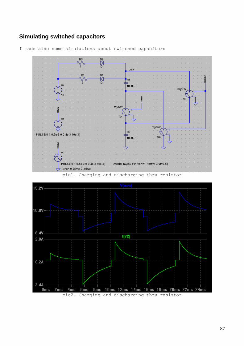
Simulating switched capacitors I made also some simulations about switched capacit ors
pic1. Charging and discharging thru resistor
pic2. Charging and discharging thru resistor

88
pic3. “rotating” capacitor with coil
pic4. “rotating” capacitor with coil simulation
* this setup somehow similar to synchronous rectifi er

89
pic5. “rotating” capacitor with resistor
pic6. Simulation results for “rotating” capacitor w ith resistor
Links: http://scholar.lib.vt.edu/theses/available/etd-173510281975580/unrestricted/chapter2.pdf http://www.irf.com/product-info/fact_sheet/farnell/ 10142.pdf http://www.ti.com/lit/an/snva595/snva595.pdf

90
Switching coils and caps We tried switching caps, coils (in flyback), now we can try switching both caps and coils. Here a model for L/4L – 2C/0.5C switch. Such combin ation of switched L and C keeps resonance frequency the same. However frequency can also be adjusted as we will s ee soon.
pic1. Switching both L and C
pic2. Simulation results for switching both L and C
* notice that waveforms have offset ;-) ** coils can also be switched using diodes. Real implementation of switches is difficult. I tri ed several different setups before I got something working ok. Here one of setups which works. I use optocouplers to avoid any interference between control circuit and LC circuit.

91
pic3. Switch based on optocouplers
pic4. Trying switch with resistor (in series to pow er supply)
top – switch control, bottom - current
pic5. Trying switch with inductor (in series to pow er supply)
top – switch control, bottom - current

92
pic6. Inductor and 2C / 0.5C switching, timing adju sted for resonance
top – voltage, bottom - current
pic7. Optocouplers switch assembled on bread board
This experiment shows quite well that energy stored in LC tank does not change when we re-arranging capacitors or coils. Follow my analogy with water I can say that the amo unt of water does not change if you pour it in different size cup ☺ Links: http://en.wikipedia.org/wiki/Opto-isolator

93
Variable Inductor We already saw non-linearity and inductance variati ons due to saturation. This effect can be used to create a variable induct or, electrically controlled variable inductor. Below shown one of the simplest setups which allow create variable inductor. We need two identical ring cores with two identical coils on each inductor. One pair of coils connected “co-directional” and se cond pair connected “in opposite” direction. One pair will be used to contr ol inductance and other will be “variable” inductor.
pic.1 Two ring cores Ferroxcube FE25 3E25 25/14/10 2x18 turns on each L1 = 2080uH L1 + L2 = 4186 uH
pic.2 experimental setup current adjusted with potentiometer inductance measured with L – meter
I,ma 0 4 8 12 16 28 48 72 88 140 200 L,uH 4186 4228 4400 4255 4200 3980 3253 2424 1978 840 383
tab1. Inductance vs. control current

94
pic.3 inductance (L,uH) vs control current (I,ma)
pic4. Comparison of measured inductance with theore tically calculated based
on formula used for non-linear inductance. blue – e xperimental; red - theoretical

95
pic5. Same setup but bigger cores used
pic6. Even bigger cores
96
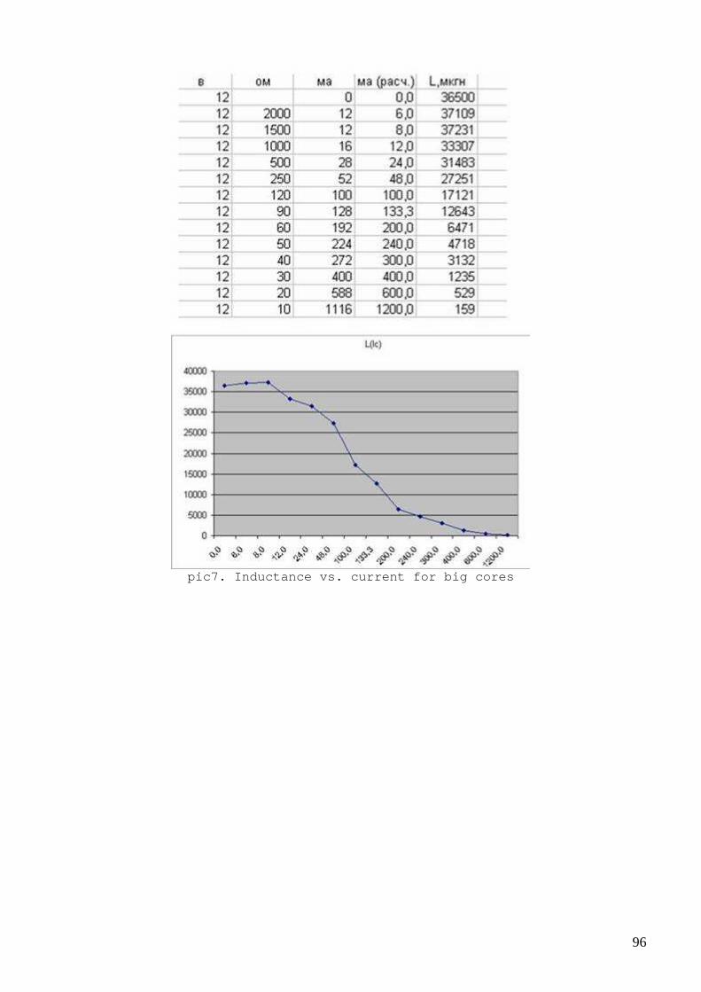
pic7. Inductance vs. current for big cores

97
pic8. This a page from old russian book with differ ent variable inductors setups shown Some links: http://translate.google.com/translate?sl=auto&tl=en &js=n&prev=_t&hl=en&ie=UTF-8&u=http%3A%2F%2Fwww.hcrs.at%2FPARAMET.HTM http://jnaudin.free.fr/html/paraconv.htm

98
Magnetic amplifiers Let’s consider one of traditional application of va riable inductor – magnetic amplifier. If we make “primary” coils in variable inductor wit h many turns and “secondary” coils with small number of turns we can control our variable inductor with small current and build an amplifier out of it. Below measured inductance vs. current for coils sho wn on pic.2
I,ma 0 2,7 3,6 4 5,1 7 10 15,2 21 26,7 30,5 40 50,7 L,mH 35,1 39 37,2 28,4 26,9 21,8 17,2 9,1 5,7 3,4 2,47 1,26 0,75
tab1. Measuring Inductance vs. control current
pic1. Inductance vs. control current (ma)
pic2. coils two ring cores Ferroxcube FE25-3F3 I 11m -> 250t ф0.35 II 1.5m -> 25t ф0.5
Now we can try building simple magnetic amplifier
99
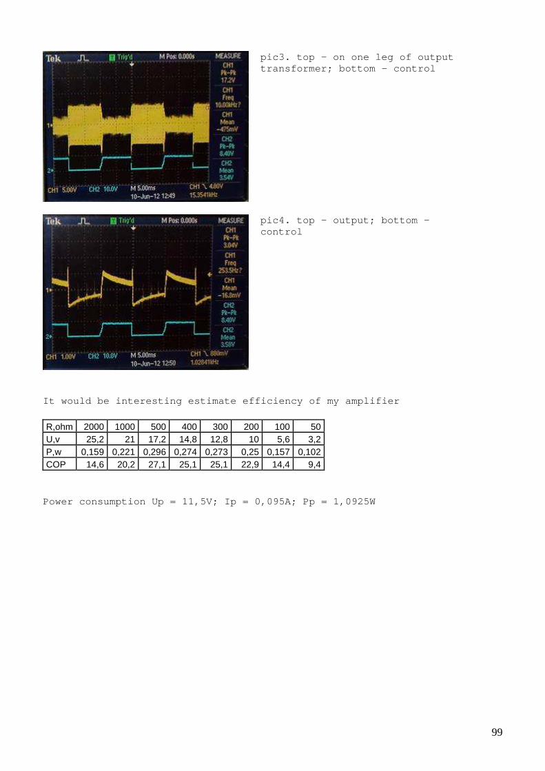
pic3. top – on one leg of output transformer; bottom - control
pic4. top – output; bottom – control
It would be interesting estimate efficiency of my a mplifier R,ohm 2000 1000 500 400 300 200 100 50 U,v 25,2 21 17,2 14,8 12,8 10 5,6 3,2 P,w 0,159 0,221 0,296 0,274 0,273 0,25 0,157 0,102 COP 14,6 20,2 27,1 25,1 25,1 22,9 14,4 9,4
Power consumption Up = 11,5V; Ip = 0,095A; Pp = 1,0 925W

100
pic5. Trying measure COP of my magnetic amplifier ( COP in percents vs R load in ohms)
pic6. Experimental setup
* two secondary winding 24v from small power transf ormer used as output transformer

101
pic7. Experiment schematic (hi frequency about 15 K Hz, low frequency about 1 KHz) It’s probably not very useful model but it is inter esting if we can simulate magnetic amplifier.
pic8. Model for magnetic amplifier

102
pic9. Simulation of magnetic amplifier
It is interesting why some people tend to believe t hat magnetic amplifiers have some “magic” properties e.g. can have COP more than 100%. What is actually different from a “regular” amplifier which uses transistors? (Power for output signal coming from power source i n both cases) Links: http://sparkbangbuzz.com/mag-audio-amp/mag-audio-am p.htm http://www.rfcafe.com/references/popular-electronic s/magnetic-amplifiers-jul-1960-popular-electronics.htm http://www.themeasuringsystemofthegods.com/magnetic %20amplifiers.pdf http://www.grimeton.info/long_wave_transmitter.html http://earlyradiohistory.us/1920alt.htm

103
Parametric resonance - other interesting type of resonance I would like to mention
pic1. Parametric resonator with variable inductor a nd a bit of theory We can see that not only current variation but also inductance variation affects voltage on the inductor (usually inductance is constant, so second term is zero).

104
pic2. Simulation for sinusoidal control current
pic3. Simulation for sinusoidal control current wit h offset

105
Simulation made using finite difference method to s olve differential equation shown above. Below two examples of parametric resonators from pa tents
pic4. Mechanical parametric resonator with variable capacitor (see patent 4522510)
pic5. Parametric resonator with electrically contro lled inductor Mechanically controlled inductance is also possible , inductance can be changed e.g. by changing coils relative position or orientation.

106
pic6. One of setups which were used by L. Mandelsta m. Inductance controlled by changing distance between coil and aluminum plate. Links: http://www.tuks.nl/pdf/Reference_Material/Mandelsta m_Papalexi/Concerning%20the%20Excitation%20of%20Electrical%20Waves%20Through %20Parameter%20Changes%20English%20translation%201934.pdf http://www.tuks.nl/pdf/Reference_Material/Mandelsta m_Papalexi/ http://www.animations.physics.unsw.edu.au/jw/AC.htm l http://aa1tj.blogspot.fi/2012/02/dl3pbs-all-tunnel- diode-parametric.html
Building parametric resonator Let’s try building parametric resonator ourselves. We can use variable inductor from our previous expe riments.
pic1. Parametric resonator experiment I use signal generator and audio amplifier to contr ol variable inductor. Below shown waveforms for different modes of oscill ations in parametric resonator.
107
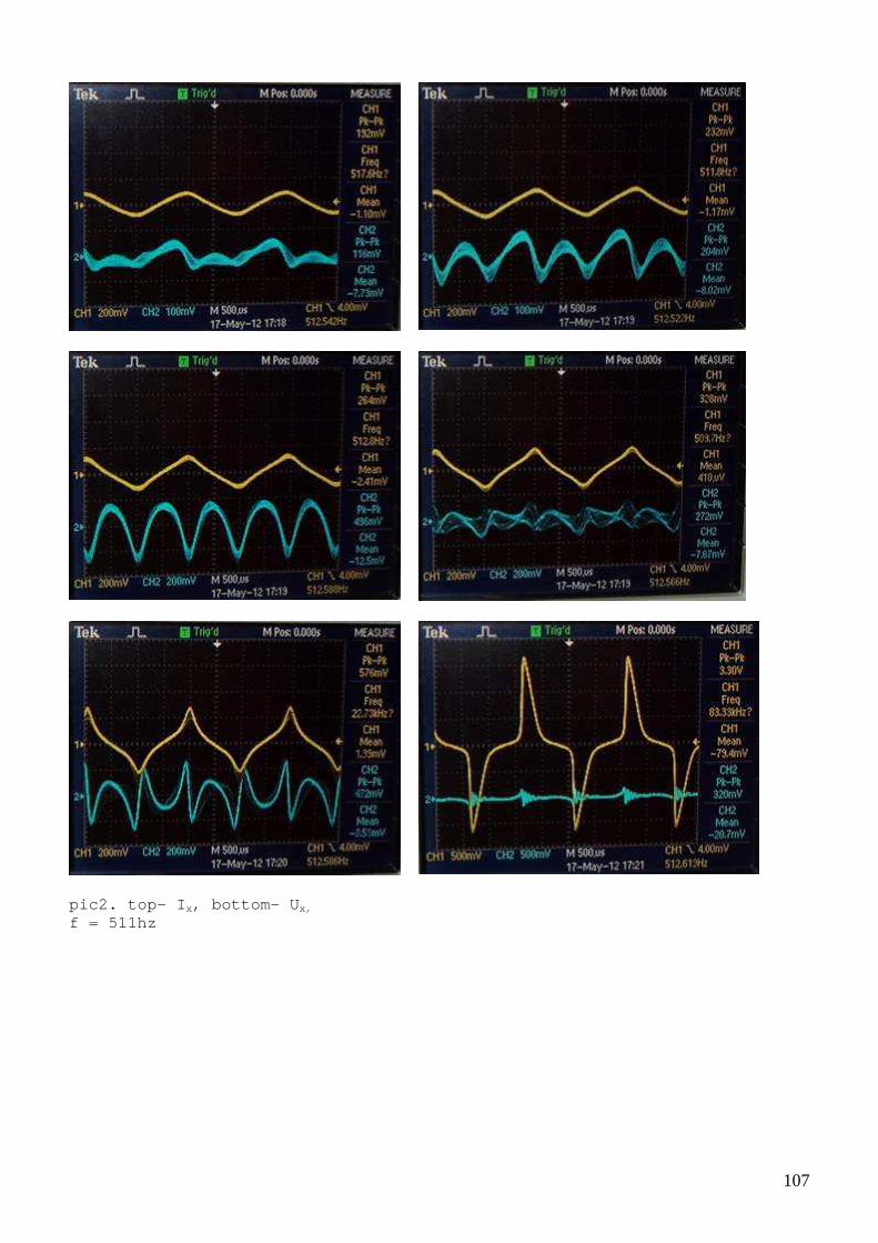
pic2. top- I x, bottom- U x,
f = 511hz

108
Same circuit but 2x control frequency
pic3. top- I x, bottom - U x, f = 911hz This is very interesting setup, our variable induct or has “inductive” input reactance, so theoretically we can have “normal” re sonance in a control circuit and parametric resonance on the output ;-)

109
Standing waves or resonance in a media So far we observed resonance which was ”localized” in components or circuit but it is possible to have a dimensional resonance when oscillations occurs e.g. due to limited propagation velocity and reflec tions. As first example let’s see a resonance in 10m long coaxial cable shorted at one end (1/4 wave resonance, frequency near 8 MHz).
pic1. Generator I used for this experiment
pic2. Power amplifier

110
pic3. Experimental setup
pic4. Resonance in coaxial cable top – voltage on the amplifier output, bottom – on the end of the line
pic5. Same but frequency adjusted a little
Links: http://physics.info/waves-standing/ http://en.wikipedia.org/wiki/Reflections_of_signals _on_conducting_lines http://www.youtube.com/watch?v=Il_eju4D_TM

111
Waves in ferrite core There can be different type of media where resonanc e occur, sound waves inside some objects can produce very powerful reson ance. See this for example http://www.youtube.com/watch?v=17tqXgvCN0E ☺ Similar effects can be created in ferrite cores. Co nventional use of this effect is ultrasonic sound sources but perhaps, one day we can find some other interes ting applications.
pic1. How oscillations occur in a rod
pic2. How oscillations occur in a ring core
I made a small Java program which simulate waves (b ased on wave equation) Here a video with results captured https://www.dropbox.com/s/annxxvnmh8chq9v/wave.flv and here Java application itself https://www.dropbox.com/s/4dmte1747d4lbe9/wave.jar (source code included) It is easy to modify the program to simulate differ ent setups.
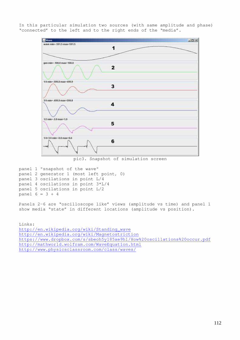
112
In this particular simulation two sources (with sam e amplitude and phase) “connected” to the left and to the right ends of th e “media”.
pic3. Snapshot of simulation screen
panel 1 "snapshot of the wave" panel 2 generator 1 (most left point, 0) panel 3 oscilations in point L/4 panel 4 oscilations in point 3*L/4 panel 5 oscilations in point L/2 panel 6 = 3 + 4 Panels 2-6 are “oscilloscope like” views (amplitude vs time) and panel 1 show media “state” in different locations (amplitud e vs position). Links: http://en.wikipedia.org/wiki/Standing_wave http://en.wikipedia.org/wiki/Magnetostriction https://www.dropbox.com/s/sbeoh5y185xe9h1/How%20osc illations%20occur.pdf http://mathworld.wolfram.com/WaveEquation.html http://www.physicsclassroom.com/class/waves/

113
Chapter 4. Bifilar coils
Permanent magnets and magnetic fields of different coils is a next to pic I would like to discuss.
pic1. Ring magnets
pic2. Magnetic flux density vs distance from magnet for ring magnet

114
pic3. Rectangular magnets
pic4. Magnetic flux density vs distance from magnet for rectangular magnet
115
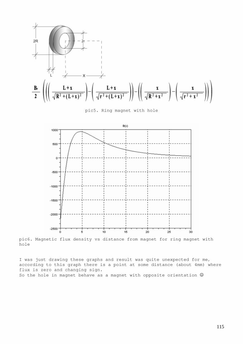
pic5. Ring magnet with hole
pic6. Magnetic flux density vs distance from magnet for ring magnet with hole I was just drawing these graphs and result was quit e unexpected for me, according to this graph there is a point at some di stance (about 4mm) where flux is zero and changing sign. So the hole in magnet behave as a magnet with oppos ite orientation ☺
116
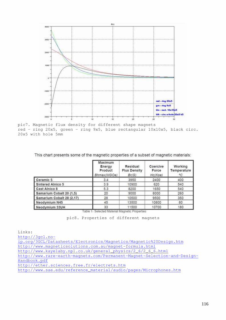
pic7. Magnetic flux density for different shape mag nets red – ring 20x5, green – ring 9x5, blue rectangular 10x10x5, black circ. 20x5 with hole 5mm
pic8. Properties of different magnets
Links: http://3gcl.no-ip.org/3GCL/Datasheets/Electronics/Magnetics/Magnet ic%20Design.htm http://www.magneticsolutions.com.au/magnet-formula. html http://www.kayelaby.npl.co.uk/general_physics/2_6/2 _6_6.html http://www.rare-earth-magnets.com/Permanent-Magnet- Selection-and-Design-Handbook.pdf http://ether.sciences.free.fr/electrets.htm http://www.sae.edu/reference_material/audio/pages/M icrophones.htm

117
Magnetic field of a”regular” coil There is a lot of confusion about magnetic field an d especially about anti-aligned or opposed magnetic fields. Some people tend to believe that field lines and po les are exist in reality, also often said that fields “adding” or “compensati ng” each other. When you use geographical map, are you expecting to see geodesic lines on the field or mountain? ;-) No, of course not. We k now that these are “imaginary” lines showing places with equal height. Please remember about this when dealing with fields in physics. Don’t mi x math which used for calculations with reality.
pic1. Magnetic field of solenoid, see (1) for more details.

118
pic2. Magnetic field of solenoid calculated using formula above
pic3. Magnetic field lines, see (1) for more detail s.
Links: http://web.mit.edu/8.02t/www/materials/StudyGuide/g uide09.pdf (1) http://en.wikipedia.org/wiki/Helmholtz_coil http://ocw.mit.edu/ans7870/8/8.02T/f04/visualizatio ns/magnetostatics/24-coilsopposed/24-coilsopposed320.html http://homepages.ius.edu/kforinas/physlets/magnetis m/magnetism.html http://www.rakeshkapoor.us/ClassNotes/MagneticField duetoCurrent.html

119
Simple magnetic field probe Before going into details, I would like to warn you . Even mainstream medicine accepts that pulse magneti c fields have very significant effect on human body and consciousness, not always positive effects. It is known that about 10% of animals can feel magn etic fields. Some people also can feel and even see fields but due to curren t social conditions these skills are not appreciated, so most people are not even aware that it is possible. To avoid any potential damage we can (must) build s imple magnetic field probe.
pic1. Probe’s schematic
* second LED is optional Wind some coil on the ferrite rod and attach LED th ru 1k resistor. You can use this probe as indicator and as a safety tool.
pic2. Picture of my probe
* Assembled on a wood ruler ** One layer coil, 0.4mm wire on ferrite rod (mu = 400) When you see LED glowing, it means that strength of magnetic field is high enough, so you should never be near that place, do not expose your body to magnetic fields until you want risk your health (an d may be life). Please note that that often results of exposure are “cumulative”, symptoms appeared after some time and grows exponentially. I t could be too late. Do not neglect your health and safety! Now you have been warned.
120
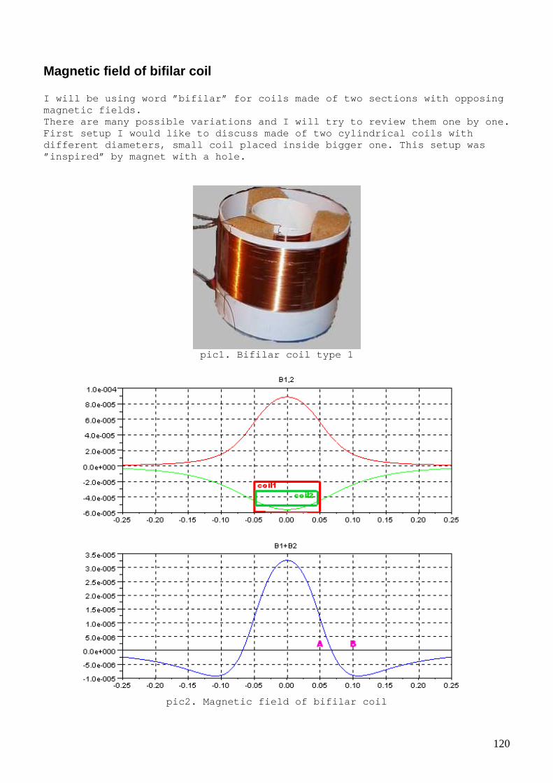
Magnetic field of bifilar coil I will be using word ”bifilar” for coils made of tw o sections with opposing magnetic fields. There are many possible variations and I will try t o review them one by one. First setup I would like to discuss made of two cyl indrical coils with different diameters, small coil placed inside bigge r one. This setup was ”inspired” by magnet with a hole.
pic1. Bifilar coil type 1
pic2. Magnetic field of bifilar coil

121
top – red magnetic field of outer(bigger) coil, gre en - magnetic field of inner (smaller) coil, bottom – resulting magnetic field (sum) Please note that this graph represent Bz, component of B which is directed along central axe of the coils. Don’t be confused, there is a magnetic field at the point where Bz = 0, it is just have vector B perpendicular to z. It is similar to situation when two magnets face ea ch other with same poles. Field in the middle is not zero, only horizontal co mponent (on pic2a) is zero in the middle point.
pic2a. Magnetic field lines of two “opposed” magnet s
pic3. Driver schematic

122
pic4. Experimental setup
Coils parameters: Inner coil diameter 5cm, outer coil diameter 10cm, height (of winding) 5,5cm, Approximately 140 turns, wire 0,4mm Inductance of outer coil L 10 = 1415uH, Inductance of inner coil L 5 = 450uH Inductance when coil connected “same direction” L + = 2540 uH, when connected in opposite L -- = 1292 uH
pic5. top – voltage on primary, bottom - voltage on small test coil

123
pic6. Two pickup coils (connected also in opposite) placed symmetrically related to zero Bz point (see points A and B on pic 2)
pic7. top - – voltage on primary, bottom – voltage on pickup coils (with some small load resistor) * It seems that my calculations give realistic shap e of the magnetic field, * Even symmetric bifilar pickup coils affects reson ance in primary coil when loaded. Links: http://homepages.ius.edu/kforinas/physlets/magnetis m/magnetism.html (see case B, anti parallel)

124
Magnetic field of bifilar coil 2 Next possible setup is - two cylindrical coils near each other (also known as anti aligned Helmholtz coils)
pic1. Calculation of magnetic field of ”anti aligne d Helmholtz coils”
pic2. Bifilar coil type 2

125
pic3. top-voltage on the coil, bottom – voltage on one turn coil used as magnet field sensor
pic4. When moving test coil amplitude decrease and then increase again, phase change when we cross “0” point
pic5. Phase changed
126
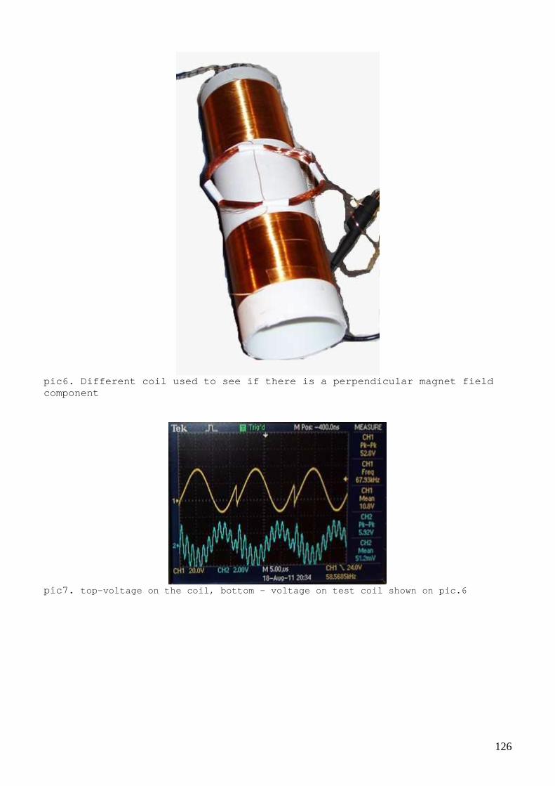
pic6. Different coil used to see if there is a perp endicular magnet field component
pic7. top-voltage on the coil, bottom – voltage on test c oil shown on pic.6

127
pic8. Two coils wound in opposite direction placed symmetrically relative to 0 point used as pick-up coils
pic9. top-voltage on the coil, bottom – voltage on two c oil shown on pic.8
* Loading pickup coils affects resonance in primary coil, again.

128
Opposite coils on ferrite rod It is interesting to see how ferrite (core) affects behavior of our setup. So I decided to try setup with two opposed coils on ferrite rod. Usually it said that core ”absorbs” magnetic field and there i s very small part of magnetic field exists outside transformer core. Wit h opposed coils it is not true, significant part of magnetic field is forced out. (this can be confirmed easily with simple magnetic field probe)
pic1. Similar setup but with ferrite
Two section of primary coil, about 200 turns each, wire 0.33mm
pic2. Moving test coil along the rod
moving small coil from left to right, minimum amplitude in the middle and phase change

129
pic3. Moving test coil and observing amplitude and phase change Often people tend to believe that bifilar coils doe s not create magnetic field and therefore bifilar pickup coils will not l oad primary coil. It is difficult to resist checking this again ;-)
pic4. Two pickup coils placed symmetrically

130
pic5. Setup for power extraction test top – on the primary coil, bottom – on pickup coils, both pairs connected in opposite Circuit consumption Ups = 11.6v, Ips = 8ma, P = 90mW
pic6. Under load R load = 1k
R,k 0,1 0,2 0,3 0,4 0,5 0,6 0,7 0,8 0,9 1 U,v 1,5 2,2 3,3 4,1 5 5,5 6,2 7 7,5 8,1 P,mW 22,5 24,2 36,3 42 50 50,4 54,9 61,3 62,5 65,6
Tab.1 Voltage on pickup coils vs load resistance

131
pic7. Voltage and power vs load resistance
Some how magic doesn’t work and we can see that loa d affect primary coils…
Opposite coils on the ring core I am continuing fun with opposite coils on ferrite cores and now I decided test ring core.
pic1. Two coils wound on ring ferrite core
Primary coils parameters: Two coils about 40 turns each (4m of wire used for each), wire 0.44mm L1,2 = 2540uH L1+2 = 9420uH L1-2 = 540uH

132
pic2. Test setup
pic2a. Test setup, coils arrangement.
Secondary coils same as primary (40 turns each)
pic3. Testing the setup, top – voltage on the prima ry, bottom – voltage on pickup coils

133
R,ohm 1 2 3 4 5 10 20 30 40 50 U,v 0,7 0,8 1 1,2 1,3 1,7 2,2 2,5 2,8 3 P,mW 490,00 320,00 333,33 360,00 338,00 289,00 242,00 208,33 196,00 180,00
Tab1. Measuring voltage vs load resistance R,ohm 100 200 300 400 500 1000 1500 2000 U,v 3,6 4,2 4,5 4,6 4,7 5 5 5 P,mW 129,60 88,20 67,50 52,90 44,18 25,00 16,67 12,50
Tab1. part 2
pic4. Voltage on the load vs load resistance

134
pic5. Power on the load vs load resistance
It is interesting that this setup shows quite ”good ” behavior under load (but it’s still not OU, at least in my tests).

135
Reversed Phi transformer - another interesting setup I would like to show.
pic. Phi transformer, picture from ”A Practical Gui de to ‘Free-Energy’ Devices” by Patrick Kelly Instead of rotating magnet and attaching load to th e coils, we can connect coils in opposite and apply some power to them. The n significant part of magnetic field will be forced out of the core on th e points where coils “connects” (points A and B). We can put a pickup co il between these two points.
pic1a. Two variants of winding of pickup coils
pic1. Pickup coil wound on a tube assembled of 8 ri ng cores (variant 1)

136
pic2. Test setup schematic
pic3. top – voltage on primary, bottom – voltage on pickup coil, does not work very well
pic4. Rewound pickup coil (variant 2)

137
pic5. top – voltage on primary, bottom – voltage on pickup coil for second setup, works better. Second attempt seems to be working ok; it has very small effect on primary under load, but also does not provide much power. Links: http://frienergi.alternativkanalen.com/Chapt1.html http://www.free-energy-info.co.uk/
Scalar coil If you take two wires and wind two coils together, then connect coils to have opposing magnetic fields you get “non-inductiv e” bifilar coil. Two variants of connection presented on pic.4 and pic.5 . Both variant will have similar magnetic field configuration.
pic1. Picture and formula for magnetic field produc ed by one turn of wire (from MIT 8.02 physics course chapter 9)

138
pic2. Magnetic field of one turn.
pic3. Magnetic field of two turns with opposite cur rents (top) and sum (bottom).

139
pic4. Parallel connection
pic5. Serial connection
pic6. Drawing field of scalar coil
top – field of separate turns, bottom – resulting s um Please note that this graph again represent only Bz , component of B which is directed along central axe of the coil. Don’t be confused, there is a magnetic field at the point where Bz = 0, it is just have vector B perpendicular to z.
140
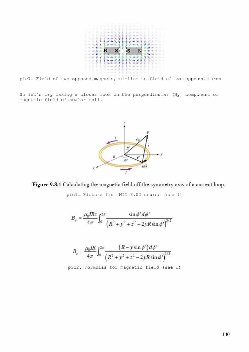
pic7. Field of two opposed magnets, similar to fiel d of two opposed turns So let’s try taking a closer look on the perpendicu lar (By) component of magnetic field of scalar coil.
pic1. Picture from MIT 8.02 course (see 1)
pic2. Formulas for magnetic field (see 1)

141
Strength of By change significantly with distance f rom the coil (y) I will draw By at tree fixed distance (3.5, 4, 4.5 cm from the coil central axe)
pic3. Field of one turn By(z) red y=4.5, green y=4, blue y=3.5
pic4a. By(z), y = 3.5 Field of two turns

142
pic4b. By(z), y = 4
pic4c. By(z), y = 4.5

143
pic5a. By(z), y = 3.5 Field of 10 turns
pic5b. By(z), y = 4

144
pic5c. By(z), y = 4.5
The simulation use very simple algorithm for integr al calculation, it can give some calculation errors. However, main point here is that fields of “scalar” coil are far non–zero and mainly located outside the coil and core (if it present). I hope this help to avoid unexpected interference a nd exposure to magnetic fields. Links: http://web.mit.edu/8.02t/www/materials/StudyGuide/g uide09.pdf (1) http://christopherbradshaw.net/The_Project_Bin/Schu mann%20Frequency%20Oscillator%20with%20Scalar%20Coil.html http://en.wikipedia.org/wiki/Bifilar_coil
145
Chapter 5. Displacement current
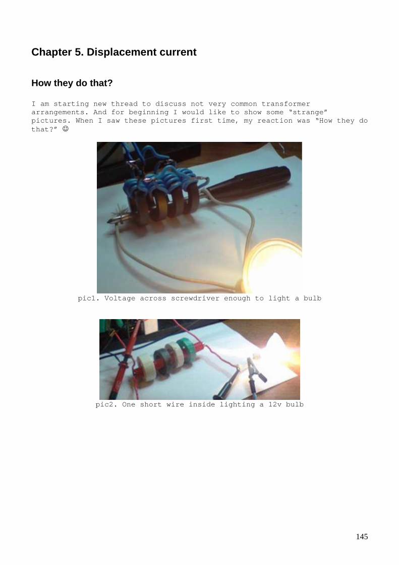
How they do that? I am starting new thread to discuss not very common transformer arrangements. And for beginning I would like to sho w some “strange” pictures. When I saw these pictures first time, my reaction was “How they do that?” ☺
pic1. Voltage across screwdriver enough to light a bulb
pic2. One short wire inside lighting a 12v bulb

146
pic3. Voltage across tweezer’s leg enough to light a bulb.
pic4. Capacitor placed inside the coil lighting a b ulb, primary coil also
capacitor
pic5. Again primary and secondary are capacitors

147
pic6. Transformer layout
pic7. If we take N transformers with N:1 windings and connect them like it shown on the picture we will get 1:1 transformer. Inductance is proportional to the square of turns. Ring with 10 turns has an inductance of 100. Ten rings in parallel have inductance 10. This is 10 times greater than a single turn.
So after consideration it appeared to be just a dif ferent step down transformer setup. After studding this subject more I found that such transformers used in different equipment and not in vention of some “smart” guy on FE forum (as it usually claimed :-). See bel ow some examples.

148
pic8. transformer from modern welding machine
pic9. Picture from http://www.classeradio.com/driver.htm (MOSFET driver)

149
pic10. Picture from http://homepage.tinet.ie/~ei9gq/pa1.html (HF amplifier) That’s fine, but what about capacitors instead of w indings? Well, it seems that transformer actually don’t care whether winding is a wire or capacitor (some combination of wires or “pl ates”). I will show more of it in next posts ;-) Links: http://homepage.tinet.ie/~ei9gq/pa1.html http://www.classeradio.com/driver.htm

150
Coaxial transformer with a «pipe» Let’s consider similar setup to what we seen in pre vious post but this time we will take a copper pipe as a primary and use jus t one wire as a secondary (and put this wire inside the pipe). Let’s do a sim ple experiment and let physicists explain why and how it works ;-)
pic. A transformer layout
pic1. Experiment with coaxial transformer (only one half used in this
experiment)

151
pic2. Schematic for the experiment
pic3. top – voltage on primary (pipe), bottom - on the secondary (single wire inside pipe) connected to a small light bulb.
pic4. top – voltage on primary (pipe), bottom – current in primary (measured on 0.03 ohm resistor) Circuit's power consumption: Ups = 11.6v Is = 245ma Ps = 2.7W
Small light bulb from car side lights used as a loa d.

152
pic5. Similar setup, different driver and ferrite r ings used
Amazingly it works! Do you see something unusual or strange in this setup?
Properties of coaxial transformer So, what’s wrong with coaxial transformer? Ok, let’ s try remember some physics.
pic1. Magnetic field of wire (see 1 for more detail s)

153
pic2. Magnetic field of the wire
1) Based on above information we can conclude that magnetic field inside a pipe (our primary) should be zero (because there is no current inside it). However why then our transformer works? How voltage /current in secondary induced? ;-)
pic3. More weird experiments to consider
2) Why phase of current in secondary same as in pri mary? (remember oscilloscope sots from previous post ?)

154
3) Let say if use single wire as a secondary we get 10v output voltage. Now if we take a longer wire and make a coil of it and insert it in side or primary… Guess what voltage we get… ok, same 10v. So we have different inductance but same voltage, i sn’t it nice? We can wound bifilar coil, other different types of coils but result will be same, same voltage on the ends. ( Still nothing strange ?) 4) We can put capacitor inside “pipe”, we will get same voltage on it. What ever we put inside e.g. screwdriver - same vol tage will be on it’s ends ☺ Links: http://web.mit.edu/8.02t/www/materials/StudyGuide/g uide09.pdf (1)
155
Displacement current in capacitor Some people say that there is a magnetic field insi de capacitor, some other people say that this magnetic field created by disp lacement current and… if we put a coil inside capacitor we will get some vol tage induced on the coil and if put load on the coil there will be no reacti on on the circuit where capacitor connected. Despite these claims sounds obscure ”philosophicall y” let’s try consider them more deeply. (Obscure, because usually we don’ t see actions without reactions in nature) When talking about magnetic field usually picture l ike this presented
pic1. Calculating magnetic field
and formula like this appeared
pic2. Magnetic field inside ”thin” capacitor accord ing to (2)
We can even draw the magnetic field using above for mula

156
pic3. Drawing magnetic field inside capacitor
However if you read explanations you see that there is definetly something wrong. To illustrate how really bad situation is I would like to quote explanations about displacement current from (2)
pic6. Quote from (2)
Sure, it is a challenge to understand what is ”virt ual” wire and ”virtual” magnetic field ;-) (see 2 for more challenges) I got impression that the only thing guys care abou t is to make their equations look nice. And what I actually would like to know - is there really displacement current and magnetic filed insi de capacitor ? After some search I found these measurements result s (see 4)

157
pic4. Magnetic field measured inside capacitor (see 4 for more details)
So it seems that there is really a magnetic field i nside capacitor.

158
pic5. Current in capacitor’s plates (picture from 6 )
However this fields caused by currents inside capac itor plates and no ”actual” current exists inside capacitor. Let’s try check other ”obscure” claims in practice ;-) Links: http://web.mit.edu/8.02t/www/materials/StudyGuide/g uide13.pdf http://www.physics.princeton.edu/~mcdonald/examples /displacement.pdf (2) http://www.phy.duke.edu/~rgb/Class/Electrodynamics/ Electrodynamics/node28.html https://www.dropbox.com/s/ijvf7o6czndn893/dc_meas.p df (4) https://www.dropbox.com/s/8l8uyqwqwk5alsm/809.full. pdf http://www.ivorcatt.org/icrwiworld78dec1.htm (6) http://download.antennex.com/preview/Nov02/Nov0602/ dca-1.pdf http://www.antennex.com/shack/Apr07/dc_factfan.pdf http://www.antennex.com/shack/Aug05/dc-final_piece. pdf http://itee.uq.edu.au/~aupec/aupec04/papers/PaperID 84.pdf http://www.overunityresearch.com/index.php?topic=21 0.0

159
Capacitor with a coil on ring core I took big ferrite ring core and put two aluminum d isks (made from cooking foil) on core sides. I made about 1/4 length gap in the disks and wound a test coil there. Here a picture (see layout on pic. 3)
pic1. “Capacitor with coil”
pic2. Experimental setup, half bridge driver connec ted to capacitor-with-coil
160
pic3. Capacitor with coil layout
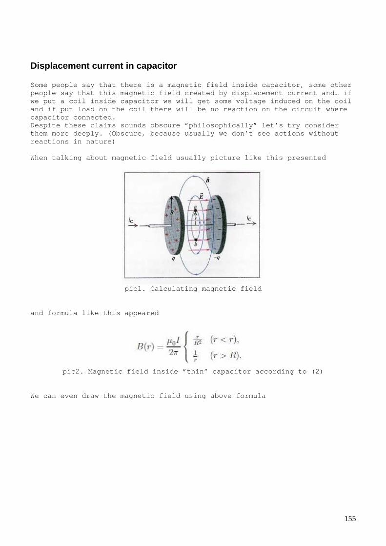
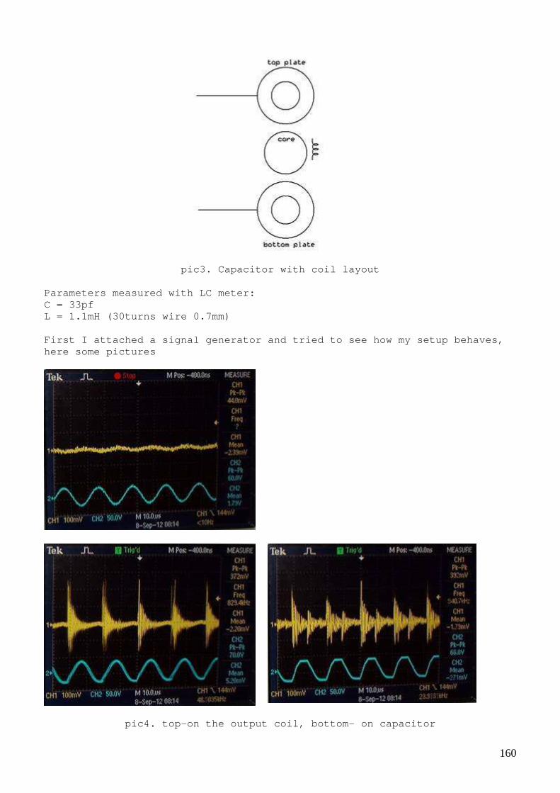
Parameters measured with LC meter: C = 33pf L = 1.1mH (30turns wire 0.7mm) First I attached a signal generator and tried to se e how my setup behaves, here some pictures
pic4. top-on the output coil, bottom- on capacitor

161
Then I tried same with half bridge driver.
pic5. ”Rectangular” pulses seems produce better results
pic6. Load resistance 10 к
Perhaps capacitance is too small.

162
Capacitor with a coil of ferrite rod After failure with “ring capacitor” I decided try s lightly different arrangement. I made a capacitor like this
and wound it on ferrite rod, than I wound a pickup coil on top of it. I used aluminum foil and got about 2000pf capacitan ce for my capacitor.
pic1. Half bridge driver, 390uH inductor and capaci tor-with-coil wound on ferrite rod

163
I decided try use resonance in primary; this could help see if load affects driver circuit.
pic2. Capacitor-with-coil on ferrite rod layout (se rial resonance)
R,ohm 50 100 200 300 400 500 1000 2000 3000 U,v 0,7 1,28 2,4 3,6 4,6 5,2 7,8 9,6 10,2 P,mW 9,8 16,38 28,8 43,2 52,9 54,08 60,84 46,08 34,68
It seems that load does not affect the much input! I can see even in some cases that amplitude on capacitor increased under l oad, but Pin/Pout ratio is far from 1. If we manage to optimize the geometr y and the driver perhaps…we can get something interesting ;-)
pic3. Voltage vs load resistance

164
pic4. Power vs load resistance
I also tried longer pickup coil and parallel resona nce in primary.
pic5. Experimental setup with longer pickup coil

165
pic6. Capacitor-with-coil on ferrite rod layout (pa rallel resonance)
R,ohm 50 130 250 500 1000 1500 2000 3000 4200 5200 6200 U,v 0,8 2 4 6,4 10 12,5 16 20,8 27,2 28,8 30 P,mW 12,8 30,77 64 81,92 100 104,2 128 144,2 176,2 159,5 145,2
pic7. top – on the capacitor, bottom – on the coil

166
pic8. Voltage vs load resistance
pic9. Power vs load resistance
I thought that this is interesting and I continued efforts in this direction.
167
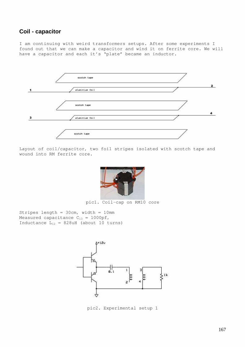
Coil - capacitor I am continuing with weird transformers setups. Aft er some experiments I found out that we can make a capacitor and wind it on ferrite core. We will have a capacitor and each it’s “plate” became an in ductor.
Layout of coil/capacitor, two foil stripes isolated with scotch tape and wound into RM ferrite core.
pic1. Coil-cap on RM10 core
Stripes length = 30cm, width = 10mm Measured capacitance C 13 = 1000pf, Inductance L 12 = 828uH (about 10 turns)
pic2. Experimental setup 1

168
We have a capacitor (points 1,4) and it is also a p rimary coil. At the same time we can use one of “plates” as a secondary coil (points 3,4) to connect some load.
pic3. top – voltage in point 1, bottom – voltage on resistor (point 3)
pic4. Resonance setup 1 (serial resonance inductor + our capacitor 14)
We can have resonance in this setup by adding extra inductor and using corresponding frequency.
pic5. top – voltage in point 1, bottom – voltage on resistor (point 3)

169
pic6. Resonance setup 2 (parallel with extra induct or)
pic7. top – voltage in point 1, bottom – voltage on resistor (point 3), frequency too small for resonance on this picture. In all these setups we can also use extra “normal” winding as a secondary and our “capacitor” as a primary winding.

170
Aligned and anti-aligned connection Thinking more about different combinations and how coil-capacitor can be used I found that there are two different connectio ns possible.
pic1. Experimental setup with coil-capacitor
pic2. Two connections
When we use points 1,2 as a capacitor connection cu rrents in ”plates” will flow in opposite directions and will have anti-alig ned magnetic fields. But if we use points 1,4 currents in ”plates” will flow in same direction and will have aligned magnetic fields. In both cases ex ternal circuit will “see” our coil-capacitor as a capacitor.
171
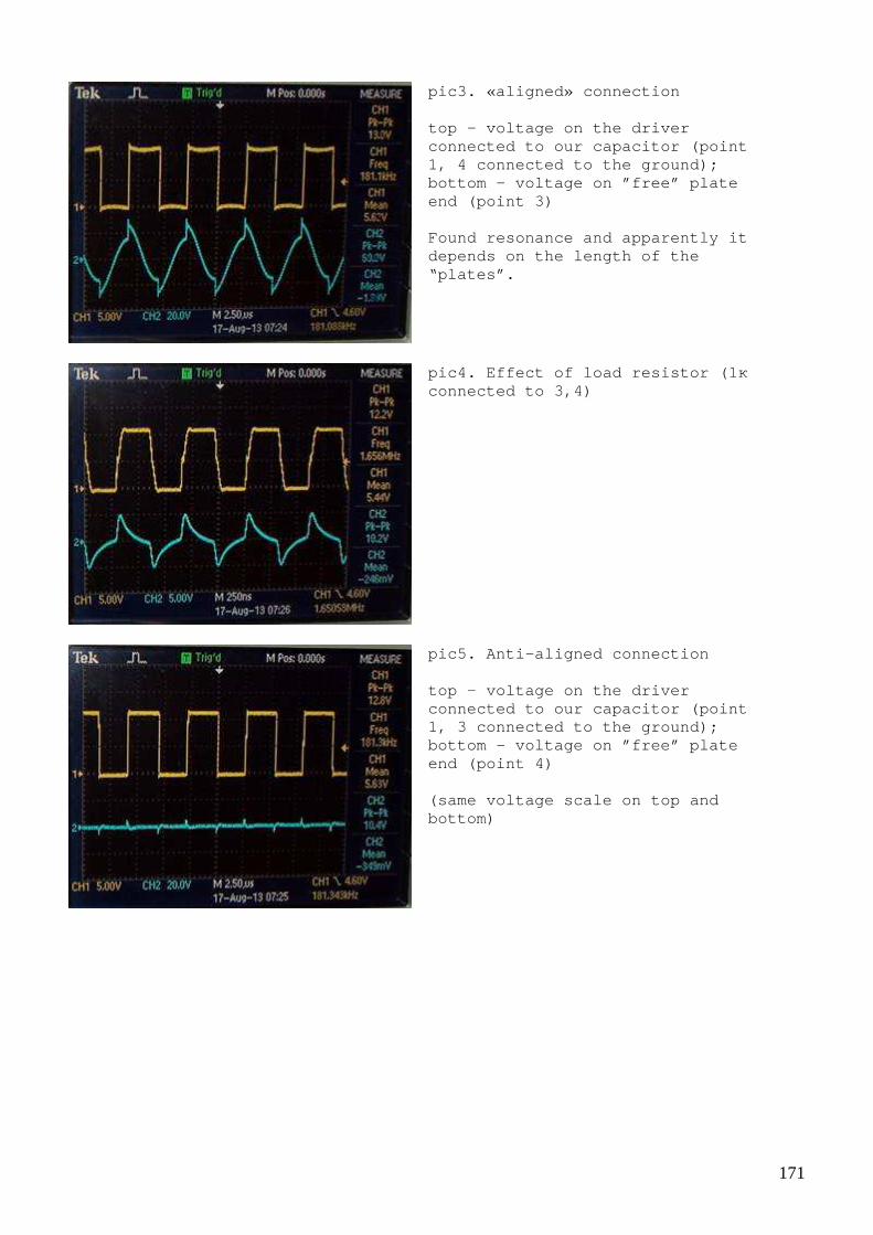
pic3. «aligned» connection top – voltage on the driver connected to our capacitor (point 1, 4 connected to the ground); bottom – voltage on ”free” plate end (point 3) Found resonance and apparently it depends on the length of the “plates”.
pic4. Effect of load resistor (1 к connected to 3,4)
pic5. Anti-aligned connection top – voltage on the driver connected to our capacitor (point 1, 3 connected to the ground); bottom – voltage on ”free” plate end (point 4) (same voltage scale on top and bottom)

172
pic6. Same as pic.5, but bigger scale on bottom
After all these exercises it seems that coil-capaci tor behaves more like a transmission line (line with distributed inductance and capacitance) Links: http://en.wikipedia.org/wiki/Transmission_line

173
Coil-capacitor on the ring core First successful experiments with coil-capacitor we re performed on RM cores; it was interesting for me to see if it will work sa me way on core with different shape, so I made a coil-capacitor on ferr ite ring core.
pic. Coil-capacitor layout, prepared to be wound on the core
I used foil stripes with length 30cm and width 15mm . I got capacitance 3400pf and inductance 270uH
pic1. Coil-capacitor on a ring core (Epcos N30 34x2 0,5x12,5)
pic2. Aligned and anti-aligned connection
I tried how aligned and anti-aligned connection wor ks

174
pic3. Anti-aligned connection (1-3) top – voltage on the driver connected to our capacitor (point 1, 3 connected to the ground); bottom – voltage on ”free” plate end (point 4)
pic4. Aligned connection (1-4) top – voltage on the driver connected to our capacitor (point 1, 4 connected to the ground); bottom – voltage on ”free” plate end (point 3)
Behavior looks very similar to coil-capacitor made using RM-10 core. Links: http://www.ferroxcube.com/prod/assets/rm10ilp.pdf
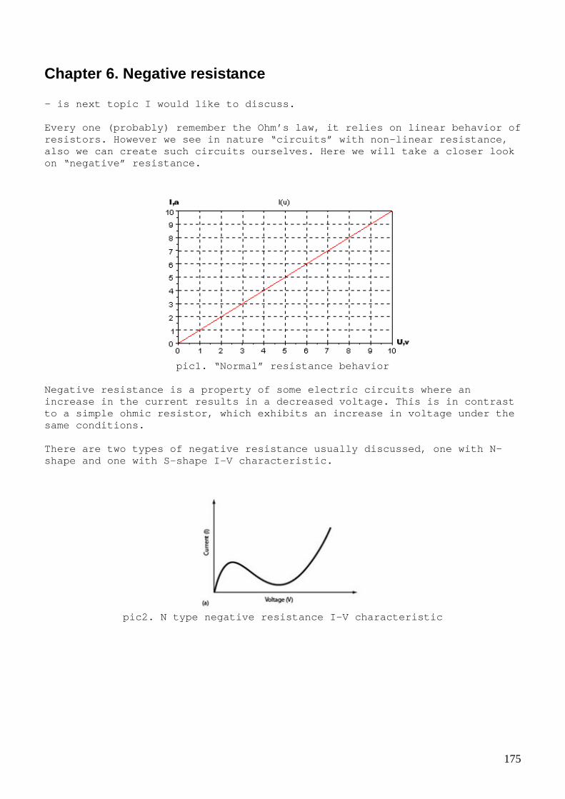
175
Chapter 6. Negative resistance - is next topic I would like to discuss. Every one (probably) remember the Ohm’s law, it rel ies on linear behavior of resistors. However we see in nature “circuits” with non-linear resistance, also we can create such circuits ourselves. Here we will take a closer look on “negative” resistance.
pic1. “Normal” resistance behavior
Negative resistance is a property of some electric circuits where an increase in the current results in a decreased volt age. This is in contrast to a simple ohmic resistor, which exhibits an incre ase in voltage under the same conditions. There are two types of negative resistance usually discussed, one with N-shape and one with S-shape I-V characteristic.
pic2. N type negative resistance I-V characteristic

176
pic2a. Here a simulation which tries to create N ty pe of negative resistance top – R(U), bottom – I(U) I think it is obvious that even resistance changes here overall behavior of circuit will be similar to “normal” resistance, so all power in the circuit comes from power source. Often people give this as an argument when they saying that “it’s negative differential resistance” and no power comes from it. Yes, it is true but only for this type of NDR. Second type of negative resistance is S type.
pic3. S type negative resistance I-V characteristic
Here some more consideration required because we ha ve to increase voltage and decrease it in order to enter negative resistan ce region. I tried make a simulation where voltage grows linearly and then de crease back to zero.

177
pic3a. Simulation of S type NDR, top-voltage, middl e-R(U),bottom-I(U)
I think it is obvious that in some cases circuit wi th negative resistance have to deliver extra power into circuit in order t o “implement” S shaped I-V curve. (Even Wikipedia admits it :-) So theoretically, if we subject some circuit with S type NDR to short pulses we could have some extra power (Short pulses needed because we have to enter negative resistance region with a minimal energy lo ses). I tried to illustrate this with the next simulation
pic4. Circuit for energy balance estimation

178
pic5. Simulation of circuit shown on pic.4
pic6.Energy consumed from power source pic7. Energy on load (R1)
I think this is very interesting theoretical conclu sion which can help us in a search for FE. There are many “natural” circuits with S shaped NDR characteristic. I will try list different NDR circuits in next post s. Links: http://en.wikipedia.org/wiki/Ohm%27s_law http://users.tpg.com.au/ldbutler/NegativeResistance .htm http://encyclopedia2.thefreedictionary.com/S-Type+N egative-Resistance+Semiconductor+Device http://en.wikibooks.org/wiki/Circuit_Idea/Revealing _the_Mystery_of_Negative_Impedance http://en.wikibooks.org/wiki/Circuit_Idea/Negative_ Resistance http://www.sparkbangbuzz.com/els/zincosc-el.htm

179
Examples of NDR with transistors Let’s see two example circuits with “artificially” created N-shape negative resistance type.
pic1. N-shape negative resistance circuit using tra nsistors
pic2. I-V curve and R(I) characteristic
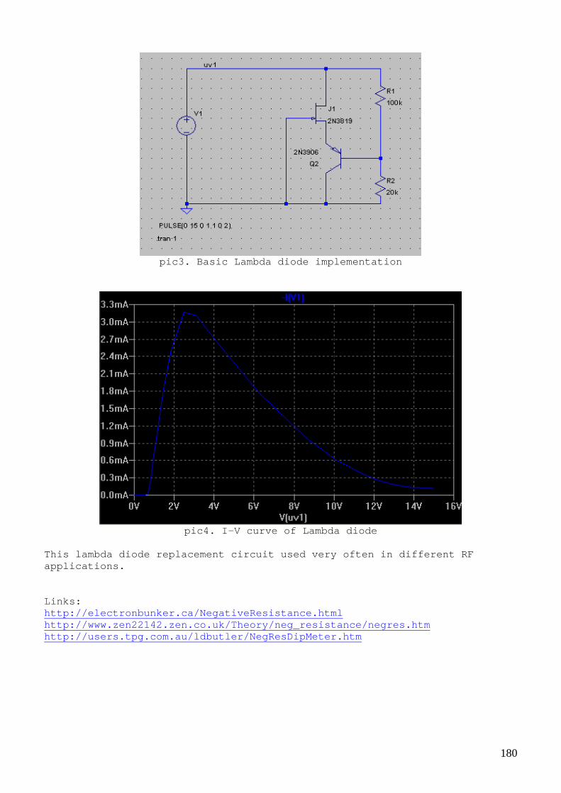
180
pic3. Basic Lambda diode implementation
pic4. I-V curve of Lambda diode
This lambda diode replacement circuit used very oft en in different RF applications. Links: http://electronbunker.ca/NegativeResistance.html http://www.zen22142.zen.co.uk/Theory/neg_resistance /negres.htm http://users.tpg.com.au/ldbutler/NegResDipMeter.htm

181
Zener diode - also can be seen as an negative resistance in som e cases
pic1. Test circuit
pic2. U,I and R=U/I for zener diode
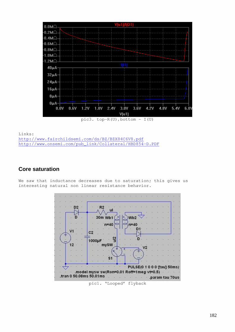
182
pic3. top-R(U),bottom - I(U)
Links: http://www.fairchildsemi.com/ds/BZ/BZX84C6V8.pdf http://www.onsemi.com/pub_link/Collateral/HBD854-D. PDF
Core saturation We saw that inductance decreases due to saturation; this gives us interesting natural non linear resistance behavior.
pic1. “Looped” flyback

183
pic2. V,I and R=V/I
pic3. I-V and R(V) graphs

184
LC circuit as negative resistance Core saturation in inductor together with capacitor can behave as negative resistance. This often causes “unwanted” oscillatio ns in power lines and serious efforts made to prevent it.
pic1. Parallel LC as NDR
pic2. Simulating parallel LC as NDR
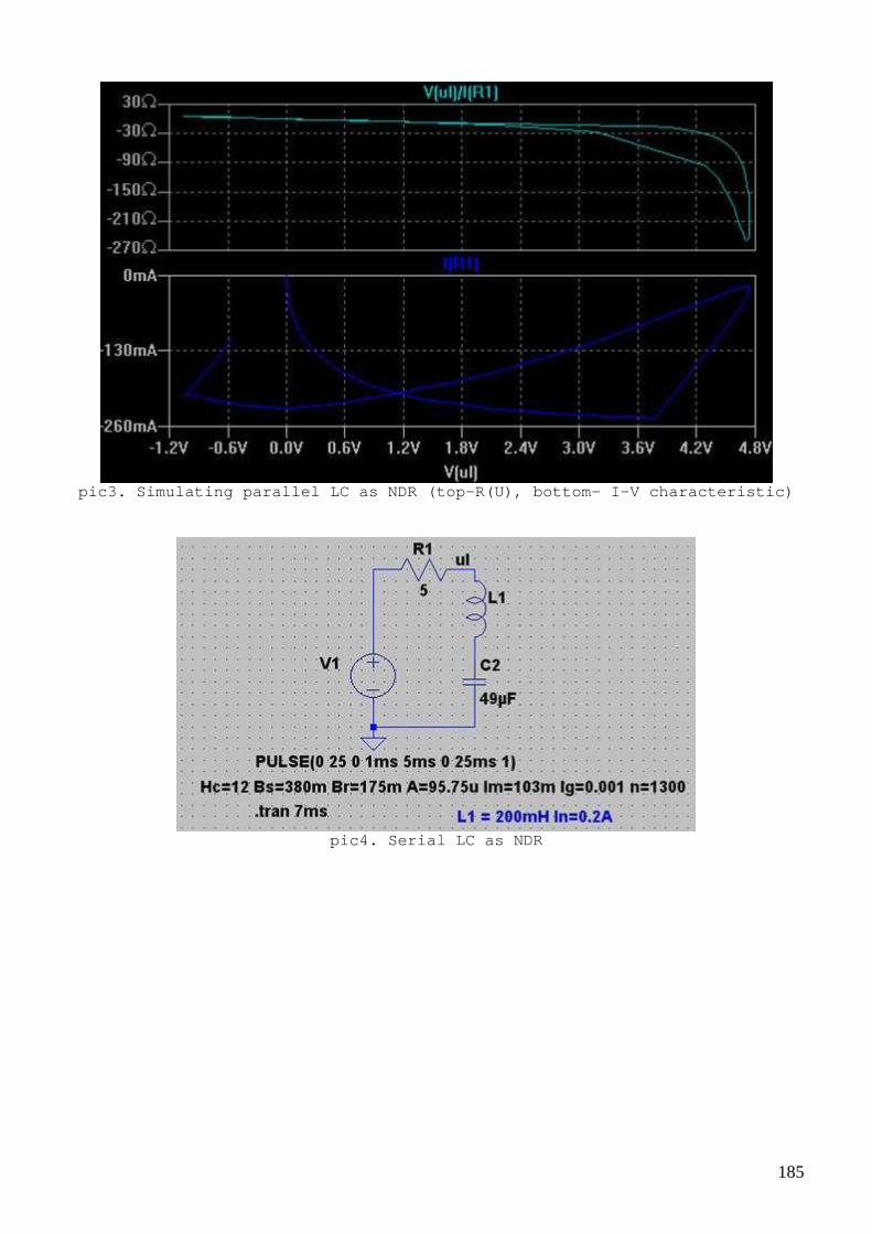
185
pic3. Simulating parallel LC as NDR (top-R(U), bott om- I-V characteristic)
pic4. Serial LC as NDR

186
pic5. Simulating serial LC as NDR
pic6. Simulating serial LC as NDR (top-R(U), bottom - I-V characteristic)

187
Avalanche breakdown effect in transistor Almost any bipolar transistor can be used as a nega tive resistance. Below shown S type I-V curve for npn transistor. (Unfortu nately can’t find any better quality picture)
pic1. I-V curve for reverse biased npn transistor

188
pic2. Test schematics with transistor in avalanche mode (see 1 for more details)
pic3. Waveforms for above circuits Links: http://jlnlabs.online.fr/cnr/negosc.htm (1) http://www.onsemi.com/pub_link/Collateral/AN1628-D. PDF http://www.elektor.com/magazines/2012/september/ele ctronics-for-starters-%287%29.2235967.lynkx (3)
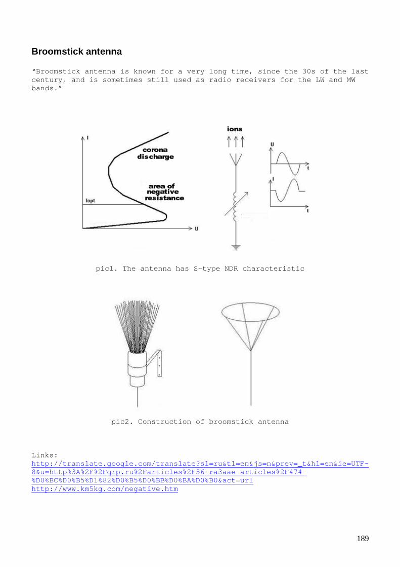
189
Broomstick antenna “Broomstick antenna is known for a very long time, since the 30s of the last century, and is sometimes still used as radio recei vers for the LW and MW bands.”
pic1. The antenna has S-type NDR characteristic
pic2. Construction of broomstick antenna
Links: http://translate.google.com/translate?sl=ru&tl=en&j s=n&prev=_t&hl=en&ie=UTF-8&u=http%3A%2F%2Fqrp.ru%2Farticles%2F56-ra3aae-arti cles%2F474-%D0%BC%D0%B5%D1%82%D0%B5%D0%BB%D0%BA%D0%B0&act=url http://www.km5kg.com/negative.htm

190
Spark gap The spark gap is most common “effect” used by FE re searchers since 19 th century. However not many researchers recognize it as S type NDR and therefore good candidate for energy source itself.
pic1. Test circuit with spark gap
pic2. Spark gap simulation

191
pic3. Same as pic.2 but larger time scale
pic4. Voltage versus current characteristics for ne on gas (turn picture 90 degree to see S shape I-V NDR) “Voltage versus current characteristics for neon ga s at 1 Torr pressure between flat electrodes spaced 50 cm. A-D dark disc harge, D-I glow discharge, I-K arc. A-B represent non-self-sustaini ng discharge and collection of spontaneously-generated ions. B-D is the Townsend region, where the cascade multiplication of carriers takes place. D-E is the transition to a glow discharge, breakdown of the ga s. E-G represents transition to a normal glow; in the regions around G, voltage is nearly constant for varying current. The region G-I repres ents abnormal glow, as current density rises. I-J represents transition to an arc discharge.” *picture and text from (1)

192
Links: http://en.wikipedia.org/wiki/Electric_discharge (1) http://mysite.du.edu/~jcalvert/phys/dischg.htm
Shorting The idea of shorting transformer secondary often di scussed on EVGRAY group. Shorting creates an “artificial” negative resistanc e and oscillations.
pic1. Model
pic2. Simulation without shorting switch

193
pic3. Simulation with switch active
In last posts I tried to show different types of ND R and theoretical possibility to get some extra energy. This is just an idea. I hope it helps somebody who wants research this subject deeper.

194
Afterword I tried present some practical stuff and provide ma ny theoretical links. I hope that is was interesting and you found somethin g new and useful. This knowledge will be a “common ground” for further dev elopment. I think that we can’t build a FE device without a precise understan ding how it supposed to work, so next book will be about different FE devic e concepts.

195
Software Simulation software used in this book can be found - LTspice IV is a high performance SPICE simulator http://www.linear.com/designtools/software/?gclid=C LbO1aT367kCFZN8cAodRQIAMQ#LTspice - Scilab is free and open source software for numer ical computation providing a powerful computing environment for engi neering and scientific applications. See www.scilab.org

196
Good luck!