Free Energy LT.pdf
14
Free Energy LT FREE ENERGY!!!! FREE INFO!!!! PEACE!!!! The free energy - in every home!!!! Please save this page, video, it contains very important information for replication!!!!!!!!!! FREE DOWLOAD INFO FILE .... MUSTAFA 007 FREE ENERGY .... IN = 250 W OUT = 6 KW FORUM .... http://realstrannik.ru/forum/39-kapanadze/47235-rabochaya-sxema-generatora-kapanadze.html
-
Upload
victor-valdez -
Category
Documents
-
view
2.064 -
download
369
Transcript of Free Energy LT.pdf

Free Energy LT FREE ENERGY!!!! FREE INFO!!!! PEACE!!!!
The free energy - in every home!!!!
Please save this page, video,
it contains very important information for replication!!!!!!!!!!
FREE DOWLOAD INFO FILE ....
MUSTAFA 007 FREE ENERGY ....
IN = 250 W
OUT = 6 KW
FORUM ....
http://realstrannik.ru/forum/39-kapanadze/47235-rabochaya-sxema-generatora-kapanadze.html

Google Translate My
Page
Gadgets
powered by
FreeEnergyLT
ANONIMUS FREE ENERGY
HG Fischer
TPU
free energy transformer
LITHUANIA EXPERIMENT
Tariel Kapanadze SECRECY
URAN235KFFM
mustafa007 NAZAR
MINIMIZATOR
Energy Saver
BOLOTOV
FREE ENERGY
TESLA
SMIT
WIND ENERGY
WATER POVER
Ismael Aviso Car
JOULE THIEF
MULLER DYNAMO
NEOGEN
BEDINI
VEGA
Bobby Amarasingam energy
PERENDEV
KAPANADZE
KAPANADZE 2
KAPANADZE 3
KAPANADZE 4
KAPANADZE 5
KAPANADZE 6
Milutin Miletic
Cold electricity
E. V. Gray Motor
Alexander Kugushov
igor_pavlovic_kuldosin
TIGER
DYNATRON
DELAMORTO
VIDEO
MY FILES
MY SITES
SITE LINK
PROGRAMS
MY ARTICLES
ANOTHER MATTER
Free counters


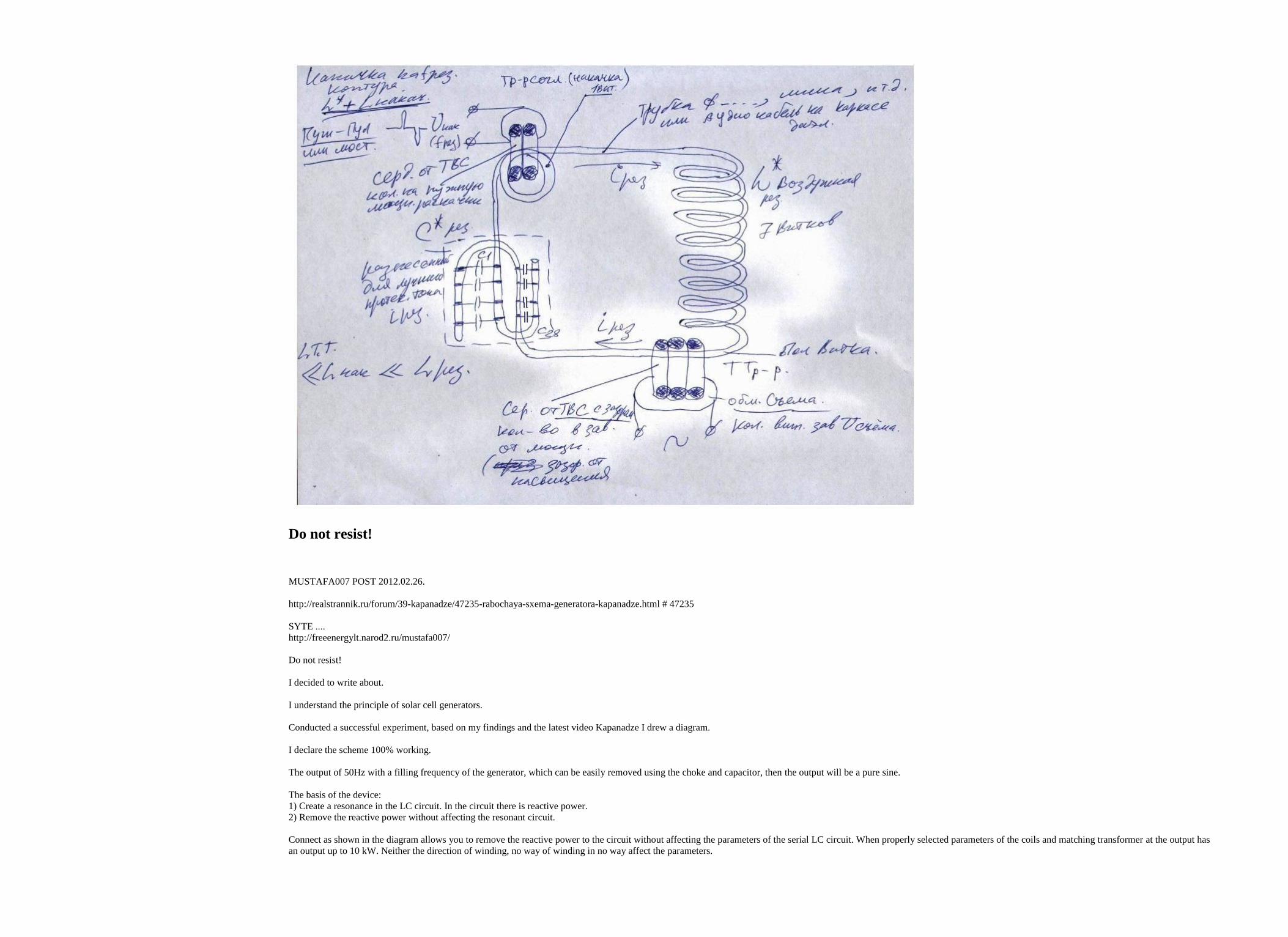
Do not resist!
MUSTAFA007 POST 2012.02.26.
http://realstrannik.ru/forum/39-kapanadze/47235-rabochaya-sxema-generatora-kapanadze.html # 47235
SYTE ....
http://freeenergylt.narod2.ru/mustafa007/
Do not resist!
I decided to write about.
I understand the principle of solar cell generators.
Conducted a successful experiment, based on my findings and the latest video Kapanadze I drew a diagram.
I declare the scheme 100% working.
The output of 50Hz with a filling frequency of the generator, which can be easily removed using the choke and capacitor, then the output will be a pure sine.
The basis of the device:
1) Create a resonance in the LC circuit. In the circuit there is reactive power.
2) Remove the reactive power without affecting the resonant circuit.
Connect as shown in the diagram allows you to remove the reactive power to the circuit without affecting the parameters of the serial LC circuit. When properly selected parameters of the coils and matching transformer at the output has
an output up to 10 kW. Neither the direction of winding, no way of winding in no way affect the parameters.

Important notes to a current transformer:
1) The primary coil is no more than one turn. Best version 0.5 turns.
2) current transformer to do on the ferrite
3) The overall mass should correspond to the reactive power in the circuit.
Important notes to the LC circuit:
1) The best result. Reactance of the capacitance at the operating frequency must be equal to the reactance of inductance on the same frequency.
2) Inductance is best done in the air, so you can achieve more reactive power.
3) The currents in this circuit sooo big lead to take not less than 4 mm can be more
4) the capacity to do the composite. If you for example need 2 uF it must be composed of 20 pieces of 0.1 uF. This is done for the distribution of flowing currents.
Everything else you see in the video is tinsel.
BB unnecessary, the inductor is unnecessary.
Also enclose a drawing which shows a device with a transformer Kapanadze.
I recommend not to do so, because such an arrangement of coils reduces the output power.
Above a certain power of changing the magnetic permeability, and the circuit upset.
This is done for the disposal of inquiring minds.
I have a different circuitry.
A test version input 250W output 6kW. It depicted a diagram of the video Kapanadze.
Consider the temporal characteristics of the serial LC circuit. At resonance, the current lags the voltage by 90 degrees. I use a current transformer overcurrent sostovlyaet, so I am submitting changes to the circuit, even at full load current
of the transformer. While working there, when the load is compensated inductors (in other words not picked up) circuit adjusts itself without letting go of the resonant frequency.
For example, the coil turns in the air six copper tubes 6mm2 diameter 100mm frame, and the capacitance of 3 pF has a resonant frequency around 60 kHz. In this circuit can be accelerated up to 20 kW reagent. Accordingly, the current
trans should have overall capacity of not less than 20 kW. You can use anything. Ring - fine, but when such facilities more likely withdrawal of the core into saturation, so we need to introduce a gap in the core, and this is the easiest way
with ferrites on TVSA. At this frequency, a core is able to dissipate about 500 watts, so it is necessary 20 000 \ 500 is not less than 40 cores.
An important condition - to create a resonance in series LC circuit. The processes occurring in such a resonance is well described. An important element - a current transformer. Its inductance should be less than one tenth circuit
inductance. If there are, the resonance will fall apart. It should also take into account the transformation coefficients, and the matching of the current transformers. The first is calculated from the impedance of the generator and the
oscillator circuit. The second depends on the voltage developed in the circuit. In the previous example, the circuit 6 turns the voltage developed at 300 volts. It turns on the coil of 50 volts. Current trans uses 0.5 turns, then the primary will
be in his 25 volts, so secondary housing must contain 10 turns to reach the voltage of 250 volts at the output.
Everything else is even in principle, and it is calculated according to classical schemes.
How will you initiate the contour irrelevant. An important part - is a matching trans, an oscillating circuit, and current trans for the removal of the reagent.
If you want this effect to realize the TT. You need to know and have experience in building high-frequency circuits. In the TT with 1/4 wave resonance, as is the separation of current and the voltage by 90 degrees. On top of tension, the
bottom current. If you spend an analogy with the submitted scheme and TT, you will see the similarity, both pumping and removal occurs on the side of the current component. Similarly, the device works, and Smith. So do not
recommend starting with CT or Smith not being experienced. But this device can literally build on the knee, while having only one tester. How to post in one of said lazj "... Kapanadze oscilloscope because of the angle seen ..."
Thus there is a modulation of the carrier. But such a decision - after all transistors with single shock can work. If they did not submit the rectified, it will be only one half wave.
modulation is needed in order so you do not suffer with the transformation of 50 HZ standard ...
To obtain the output of the sine of 50 Hz. Without it, then it will be possible to feed only a resistive load (light bulbs, heating spirals ...). The engine, or a transformer at 50 Hz will not work without this modulation.
The master oscillator, I outlined rectangle. It provides a stable frequency at which the LC circuit resonates. Pulsating voltage change (sine) is served only on weekends keys. The resonance of the tuned circuit will not bounced just in time
kzhdy in the loop to spin more or less power to the beat of the sinus. It's as if the swing talkan, with greater or lesser degree, the resonance of the swing does not change, only the energy.
The resonance of free oscillations can only disrupt the load it directly, because it changes the parameters of the contour. In this scheme, the load does not affect the parameters of the circuit, it is self-tuning. Impacting the current
transformer, on the one hand changing the parameters of the circuit and the other is changing the permeability of the transformer core, umenshaya its inductance. Thus for the circuit load "not visible". And the contour of the free vibrations
of a committed and continues to commit. By varying the voltage of keys (modulation), the only change amlituda free vibration and all. If you have an oscilloscope and generator, perform an experiment to serve on the generator circuit
resonance frequency of the circuit, then change the amplitude of the input signal. And see that there is no breakdown.
Yes, the matching transformer and current transformer based on ferrite, air resonant circuit. The more it turns the higher the quality factor, on one side. On the other higher the resistance, which reduces the ultimate capacity, because the
main power goes into heating the circuit. Therefore, you should seek a compromise. With regard to merit. Even with Q 10 at 100 W input power of 1,000 kW will reagent. Of these, 900 W can be removed. It is perfectly attuned with the
conditions. In the real world from 0.6-0.7 reagent.
But all this stuff, as compared with the fact that we should not bury the radiator and steam from the earth! And it even had Cape Island broke ground on the device! And it turns out is not nada!
Revktiv rushing and without working zazemleniya.Eto bezsporno.A here with removable current transformer, will have to mess ... Not all prosto.Obratnoe imeetsya.Stepanov effect once it is decided in the patent from him out there for
this purpose diodes narisovany.Hotya the presence of the diodes have Stepanova each interprets differently.
This option can only be set to 50 Hz resonant frequency. Since the circuit spinning high currents, respectively, the diodes are needed for strong current. For these diodes do not kHz. With vibrant trance, in a magazine article met scoop
"diode circuit," or something like that. There should be the same inductance as a consequence the number of turns.
In the current transformer. Here we must also look for a compromise. Its inductance should be as little as possible from the resonant transformer. This means a small number of turns. But the decrease in turns leads to a decrease in voltage

on the coil, as a consequence of the output (secondary housing current trance) is needed to make more turns. And this leads to a decrease in output current, due to increased winding resistance. A vicious circle. From my observations, I
wrote about it, the inductance of the primary current transformer must be less than one tenth of inductance resonating circuit. So do not hesitate to wound more turns in the primary current transformer, measuring the inductance of the
course. For 50 Hz, it will not hurt the result.
MUSTAFA007 POST 2012.02.28.
Welcome! I'm not lost. Some friends from the forum have built the circuit. Made adjustments in the design of the coil to increase the quality factor, which is very good. Created a removal that does not affect the resonant circuit, or if there
is a slight effect. Now is the time to tell someone put it, the flavor. In the next post will give a full description and block diagram. Schematic of each of the blocks, I think an experienced ham does not cost anything to create.
MUSTAFA007 POST 2012.02.29.
Many argue that a resonant circuit, as a true and resonance, nothing is impossible to remove. Applying the classical method of removal is really off-resonance with the extra energy it can not simply take from there. To understand the
effective method of removal is necessary to know and understand classical music circuit work. Pretty good description is here http://www.meanders.ru/energyrezonans.shtml sure to read before continuing read more, refresh the memory.
And a pretty clear conclusion, "The law of conservation of energy has not been canceled! Perpetual motion machine based on the resonance does not happen, and can not be! When using an oscillatory circuit, there is an accumulation of
energy cherezperiodnoe current source, so as a result of the accumulation, at some point in time the energy of the circuit may exceed the energy supplied to it. The energy of the "emptiness" can not appear. "In the judgment I'm from the
energy conservation law does not go my way, and in every way try to correct the idea of passing it through this" filter ".
Perhaps I'll start with "interview with Tesla's lawyer," because it does not explain it more understandable.
Lawyer
I understood very little of your application, some time ago when you
have reported the use of several thousand horsepower for charging the capacitor and the receipt of
million hp when it is discharged. I'd be very surprised if you get the same
on this machine.
Tesla
Yes, I charge the capacitor 40.000 volts. When it was fully charged, I discharged
it at once, after a short circuit, which gave me a scale of very fast oscillations.
Let us suppose that I charge the capacitor 10 watts. For such a wave energy flux is
(4 X 10⁴) 2, and this, multiplied by the rate of 100,000. You see, so you can get thousands of
or millions of HP
Lawyer
I would like to clarify: it depended on the suddenness of (fast) discharge?
Tesla
Yes. This is - just an electrical analog of copra, or hammer. You accumulate energy from the
by distance traveled, and then you release it with a huge surprise
(Speed). The distance that overcomes the mass-· low, so the pressure
turns out great.
We return to these words, "When the oscillatory circuit is cherezperiodnoe energy storage power source." Note the accumulation of energy in the capacitor requires constant current, and if we divide the time of the capacitor charge, he
always resisted the charge. The work is an oscillatory circuit at resonance does not cause resistance when it "charges". On the contrary, it absorbs energy from the source. It is therefore very important to have a chain of removal, which
will not, or if so, at a minimum, to make the distortion of the parameters of the circuit, tearing off resonance. Thus, small portions of energy is a "charge" of the circuit. "You accumulate energy from the
by distance traveled, and then you release it with a huge surprise
(Speed) ... so the pressure
turns out great.
Suppose the circuit with each pulse are making 100 watts of energy, consuming 100 watts of power + losses. For 10 of the pump pulses, the circuit have 1 kW - · loss. Now, on the 11th pulse contour remove from 1kW of energy, again
waiting until the accumulated energy of the circuit. And so on. Proceeding from this. There should be a dynamic removal. Let's say if the frequency of the resonant circuit 100 kHz, 10 kHz and eat, we have an increase of 10. As in the
"lever".
A quote from the translation of Don Smith:
"Well, what about the pulsing electronic system voltage? As the output power of such a system
will depend on the growth of tension? Our first thought suggests that the power can be a little
increase, but then remember the formula Watts = Volts x Amps, ie if we increase the voltage by half,
capacity will be doubled. And we agree with the inference that is not really true.
Don Smith points out that since the capacitors and inductors store energy, and they included
in the chain, then the output will be proportional to the square of the voltage in the circuit. Udvoy voltage
and power output increased fourfold. Increase the voltage by 3 times and the capacity will increase by 9 times. In 10
fold increase in voltage, and power will increase by 100 times!

Don says that the energy stored in the system multiplied by the pulsation cycles per second (hertz) - a ·
power system swings (not her). Inductors and capacitors to temporarily accumulate
electrons, and their effectiveness is shown by the following formula:
The formula for the capacitance:
W = 0.5 x C x V x Hz
where:
W - energy in joules (J = volts x amps x seconds)
C - capacitance in Farad
V - voltage
Hz - the frequency of vibrations per second (Hertz)
The formula for the inductance:
W = 0.5 x L x A x Hz
where:
W - energy in Joules
L - the inductance in Henry
A - current in amperes
Hz - the frequency in hertz
Have you noticed that if there is an inductance (coil in the circuit), the output power increases by
square of the current in the circuit. Twice the voltage and twice the current yield increase in power four times because of the
voltage, and this power has multiplied four-fold increase due to the increase of current, giving the total
increase in power output by 16 times.
Have you noticed the formulas that the output power is directly proportional to the frequency of oscillations in
chain (the number of pulses per second). It does not come all at once intuitively. If vdoe increase the frequency of
pulses, the power is doubled. When it catches up, once you begin to understand why Tesla
using millions of volts and millions of pulses per second.
Don Smith said that when the chain c oscillating circuit is at resonance with the frequency
ripple, loop resistance drops to zero, and this chain becomes a superconductor. The energy of the system
at the resonance point:
W = 0.5 x C x V x (Hz)
where:
W energy in Joules
C capacitance in Farad
V the voltage in volts
Hz frequency in Hertz
If so, then an increase in frequency in the resonant circuit has a huge impact on the output power
device.
I think this information is sufficient to close all inferences in a single chain.
Therefore turn to an analysis flowchart devices.
The left side of the pump oscillator circuit, which operates on a push-pull circuit, and controlled PWM controller (you can use the TL494). The width of the pulse from this generator is regulated by feedback from the oscillator circuit.
Upon reaching a certain power in the circuit, changing the pulse width to decrease, so the next pulse will make the circuit less energy while maintaining the energy level in the circuit at the same level.
The right side of the controller circuit built pickup. It also has a pulse width of the PWM controller which varies according to a sinusoidal signal from the oscillator 50 Hz. In the circuit from the generator to a sine PWM controller is an
amplifier with adjustable gain, which is controlled by the output voltage. This technique is necessary to maintain the output voltage of 220 volts regardless of load. In addition to the sine PWM controller and signal output from the current
transformer to synchronize the phase of pulses of the bridge, consisting of two keys on the right and left of the current transformer. As described above, the left side of working at high frequency, low right.
----------------------------------------------
For details of all is the classic formula, who wants to do something - do it.
Mustafa, that is, the modulation of the supply voltage do you end up abandoned?
Or it never was and it was the first conditional block diagram
The first scheme - this is what I saw on the video, plus my knowledge. Modulation of her have it, I brought, because this is not a video, and standard output to get.

От модуляции в первой части схемы (левой) я отказался сразу, так как изменение количества энергии в контуре - это по меньшей мере неэффективно. Лучше энергию контура держать на одном уровне. А съём
модулировать. Таким образом в каждый момент времени снимается больше или меньше энергии с контура, и среднеквадратичное значение энергии в контуре постоянно, что есть эффективно.
Площадь круга - наши знания, периметр - незнания.
--------------------------------------
ale написал:
Conclusions:
A). мощности в контуре при последовательном резонансе гуляют нешуточные.
2). СЕ там нет. Что вложил в раскрутку "маховика", то и собрал...
Правильно, с маховика ничего не возмешь. Маховик же не колебательный контур. Если считаете его таковым, назовите резонансную частоту вращения маховика. С какой скоростью вы его крутите, на той он и вращается.
А Мустафа чего-то не договаривает.
Я все рассказал для поверхностного представления, если вам интересно понять всю суть. Произведите расчёты.
Когда в переводе Смита читал: "Вы заметили, что если присутствует индуктивность (катушка в цепи), то выходная мощность увеличивается на квадрат тока в цепи. Вдвое больше напряжение и вдвое тока дают увеличение
мощности в четыре раза из-за напряжения, и эта умноженная мощность еще увеличивается вчетверо из-за увеличения тока, давая общее увеличение выходной мощности в 16 раз."
Мягко говоря, недоумевал, какими это сказочными формулами Смит считает. Потом понял, он считает реактивную энергию, в контуре.
Как вычисляется реактивная энергия контура?
Для индуктивности:
PL = I2· Rx / 2
Для емкости:
PC = U2/2· Rx
При резонансе:
PL = PС
Энергия из индуктивности перетекает в ёмкость и назад.
Как видно из формул, при внесении в контур дополнительного тока, при следующем обороте приобретает квадратурное значение, и так на каждое внесение в контур энергии. Если интересно проведите расчёты, иначе
покачайте качели, и понаблюдайте за амплитудой.
Рассчитайте, сколько совершит контур свободных колебаний при нагрузке. Затем рассчитайте, как будет меняться количество энергии в контуре, от периода к периоду с момента когда в контуре энергия от "0" и до
рабочей мощности. Потом посчитайте, сколько необходимо совершить колебаний, для получения рабочей мощности без нагрузки.
Проводил такой эксперимент. Вносил в контур импульс по длительности равный колебательной частоте, следующий импульс через несколько секунд. На осциллографе наблюдаю затухающие колебания, амплитуда
первого примерно равна входному импульсу. Теперь подаю два подряд импульса, амплитуда около 1,5. 3 импульса примерно 5 и так далее. That is, амплитуда с каждым последующим импульсом возрастает нелинейно, и
аккумулируется. Вот преимущество резонанса.
Для резонансного контура очень важно, при нагрузке, оказывать минимум влияния на параметры контура. Над этим я долго думал, как при жёсткой связи с контуром не влиять на него. Иначе колебания затухают быстрее
уходя в компенсацию изменений параметров, чем в нагрузку. Допустим раскачали, качели и изменили один из параметров, допустим длину подвеса, энергия рассеется, колебания затухнут.
Про съем мне сразу было известно, нельзя реактив нагружать непосредственно, на каждый входной импульс, иначе просто можно нагрузку подключить к источнику. Его сперва необходимо раскачать, а затем снимать.
Вопрос про волновой резонанс был, нет его у меня, это другой тип реактива. Он возникает в контуре с распределёнными параметрами.
Интересный вопрос:
Мустафа, это не трансформатор тока , это обычный повышающий транс
Тогда изобразите токовый транс. Это условное название. Да это повышающий, ток большой величины и напряжение низкой величины в первичной, трансформируется в напряжение высокой величины и ток низкой
величины.
ПРЕДЛАГАЙУ ПОЦИТАТ ЕТОТ ПДФ ...
ТОГДА САМИ РЕСИТЕ КТО ПРАВ ...
Как рассчитывается импульсная мощность, я в курсе. Это учтено.
Так в том то и разница, что обычный транс нагрузит контур и прощай резонанс
Выше ответил. Нагружая резонансный контур непосредственно, даже один виток это ого-го. Так как у них общие электромагнитные поля, а с отдельным трансом, электромагнитные поля разные. Это я у Мельниченко
усвоил, только применил по другому.
-----------------------
Foton написал:
пока писал, Мустафа ответил. Ну чтож, тогда вопрос - Если мы будем снимать Х кВт с повышающего транса (или токового - выходного для данной схемы), то какой ток будет гулять в обмотке "согласующего" или
трансформатора "раскачки" контура?
OTVET MUSTAFA...
По вторичной обмотке согласующего, протекает тот же самый ток, ведь цепь одна. В первичке того же транса, будет наводится ЭДС, а вот тока не будет, генератор в эти моменты отключён от транса.
-----------------
Foton написал:
mustafa007 написал:
По вторичной обмотке согласующего, протекает тот же самый ток, ведь цепь одна. В первичке того же транса, будет наводится ЭДС, а вот тока не будет, генератор в эти моменты отключён от транса.
Вот, уже интереснее. А изобразить графически эти моменты можно? Это я к тому, что в моменты когда отключен ген, с первички можно снимать энергию, ведь по Вашему, там есть эдс, причем она там нехилая. Ну
должна быть .
MUSTAFA OTVET...
An interesting solution! Использовать этот же транс. Это уже усовершенствование. Меньше дополнительных индуктивностей. Это надо обмозговать.
-----------------------
2012.02.29. ...........