Francisco Borges Carreiro Comunicação Tempo-Real Embutidos ... · Elioena que me conferem o...
168
Universidade de Aveiro 2008 Departamento de Electrónica, Telecomunicações e Informática (DETI) Francisco Borges Carreiro Usando o Protocolo Ethernet em Sistemas de Comunicação Tempo-Real Embutidos Using the Ethernet Protocol for Real-Time Communications in Embedded Systems
Transcript of Francisco Borges Carreiro Comunicação Tempo-Real Embutidos ... · Elioena que me conferem o...

Universidade de Aveiro
2008
Departamento de Electrónica, Telecomunicações e Informática (DETI)
Francisco Borges Carreiro
Usando o Protocolo Ethernet em Sistemas de Comunicação Tempo-Real Embutidos
Using the Ethernet Protocol for Real-Time Communications in Embedded Systems

Francisco Borges Carreiro
Usando o Protocolo Ethernet em Sistemas de Comunicação Tempo-Real Embutidos
Using the Ethernet Protocol for Real-Time Communications in Embedded Systems Tese apresentada à Universidade de Aveiro para cumprimento dos requisitos necessários à obtenção do grau de Doutor em Engenharia Electrotécnica, realizada sob a orientação científica do Dr. José Alberto Gouveia Fonseca, Professor Associado do Departamento de Electrónica, Telecomunicações e Informática (DETI) da Universidade de Aveiro e do Dr. Francisco Manuel Madureira e Castro Vasques de Carvalho, Professor Associado da Faculdade de Engenharia da Universidade do Porto. Apoio financeiro da Unidade de Investigação IEETA da Universidade de Aveiro


O júri / The Jury Presidente / President Vogais / Examiners committee
Prof. Dr. Jorge Carvalho Arroteia Professor Catedrático do Departamento de Ciências da Educação da Universidade de Aveiro.
Prof. Dr. Carlos Eduardo Pereira Professor Associado do Departamento de Engenharia Eléctrica da Universidade Federal do Rio Grande do Sul - UFRGS, Brasil.
Prof. Dr. Francisco Manuel Madureira e Castro Vasques de Carvalho Professor Associado do Departamento de Engenharia Mecânica da Faculdade de Engenharia da Universidade do Porto (Co-orientador).
Prof. Dr. José Alberto Gouveia Fonseca Professor Associado do Departamento de Electrónica, Telecomunicações e Informática da Universidade de Aveiro (Orientador).
Prof. Paulo José Lopes Machado Portugal Professor Auxiliar do Departamento de Engenharia Electrotécnica e de Computadores da Faculdade de Engenharia da Universidade do Porto.
Prof. Dr. Luís Miguel Pinho de Almeida Professor Auxiliar do Departamento de Electrónica, Telecomunicações e Informática da Universidade de Aveiro.
Prof. Dr. Paulo Bacelar dos Reis Pedreiras Professor Auxiliar do Departamento de Electrónica, Telecomunicações e Informática da Universidade de Aveiro.


agradecimentos
A realização de uma tese de doutoramento conta com a colaboração directa e indirecta de diversas pessoas. Bem sei que corro o risco de não dar conta de expressar nominalmente o meu ‘muitíssimo obrigado’ a todos aqueles que colaboraram. Contudo devido ao seu especial envolvimento, gostaria de particularizar os seguintes agradecimentos. A José Alberto Fonseca, Professor da Universidade de Aveiro e meu orientador, a quem quero expressar meu profundo reconhecimento pelo empenho, amizade, disponibilidade, estímulo, sugestões, e apoio incondicional nos momentos mais difíceis. A Francisco Vasques, Professor da Universidade do Porto e meu co-orientador, pela disponibilidade e inestimáveis contribuições que em muito ajudaram a valorizar o meu trabalho. A Luis Almeida e Paulo Pedreiras pelas sugestões e clarificações em diversos assuntos discutidos ao longo deste trabalho. A Joaquim Ferreira pela amizade e discussões científicas. A Valter Silva pelas sugestões, discussões científicas e principalmente em programação dos microcontroladores e por sua amizade. Aos colegas Ricardo Marau, Filipe, Vasco, Maxmauro, Manuel Barranco, Iria, Arnaldo, Whatney e muitos outros que tive contacto no DETI durante o desenvolvimento deste trabalho. E por últimos mas não os últimos quero agradecer a minha esposa e filhos. A Neldeci pelo suporte incansável de esposa e aos filhos Francisco Filho e Elioena que me conferem o orgulho de ser pai.


palavras-chave
Tempo-real, ethernet, barramentos de campo, passagem de testemunho virtual, VTPE
resumo
Os Sistemas Computacionais de Controlo Distribuído (SCCD) estão muitodisseminados em aplicações que vão desde o controlo de processos e manufactura a automóveis, aviões e robôs. Muitas aplicações são de natureza tempo-real, ou seja, impõem fortes restrições às propriedades subjacentes aos sistemas de controlo, gerando a necessidade de fornecer um comportamento temporal previsível durante períodos alargados de tempo. Em particular, dependendo da aplicação, uma falha em garantir as restrições pode causar importantes perdas económicas ou mesmo pôr vidas humanas em risco. Actualmente, a quantidade e funcionalidade dos modernos SCCD têm crescido firmemente. Esta evolução é motivada por uma nova classe de aplicações que requer maior demanda de recursos tais como aplicações de multimedia (por exemplo visão), bem como pela tendência em usar grande número de processadres simples e interconectados, em vez de poucos e poderosos processadores, encapsulando cada funcionalidade num único processador. Consequentemente, a quantidade de informação que deve ser trocada entre os nós da rede também cresceu drasticamente nos últimos anos e está agora atingindo os limites que podem ser obtidos por tradicionais barramentos de campo, como por exempo CAN, WorldFIP, PROFIBUS. Outras alternativas são pois requeridas para suportar a necessidade de largura de banda e a manutenção de exigências dos sistemas de comunicação tempo-real: previsibilidade, pontualidade, atraso e variação de período limitados. Uma das linhas de trabalho tem apostado na Ethernet, tirando vantagem dos baixos custos dos circuitos, da elevada largura de banda, da fácil integração com a Internet, e da simplicidade em promover expansões e compatibilidade com redes usadas na estrutura administrativa das empresas industriais. Porém, o mecanismo padronizado de acesso ao meio da Ethernet (CSMA/CD) é destrutivo e não determinístico, o que impede seu uso directo ao nível de campo ou pelo menos em aplicações de comunicação tempo-real. Apesar disso, muitas abordagens diferentes têm sido propostas e usadas para obter comportamento tempo-real em Ethernet. As abordagens actuais para dotar de comportamento tempo-real Ethernet partilhada apresentam desvantagens tais como: exigência de hardware especializado, fornecimento de garantias temporais estatísticas, ineficiência na utilização da largura de banda ou na reposta tempo-real. São ainda por vezes inflexíveis com respeito às propriedades de tráfego bem como com as políticas de escalonamento. Podem exigir processadores com elevado poder de cálculo. Finalmente não permitem que estações tempo-real possam coexistir com estações Ethernet standard no mesmo segmento. Uma proposta recente, o algoritmo hBEB, permite a coexistência de estações tempo-real e standard no mesmo segmento. Contudo, apenas uma estação tempo-real pode estar activa, o que é inaceitável para aplicações deautomação e controlo. Esta tese discute uma nova solução para promover tempo-real em Ethernet partilhada, baseando-se na passagem implícita de testemunho de formasimilar à usada pelo protocolo P-NET. Esta técnica é um mecanismo de acesso ao meio físico pouco exigente em termos de processamento, sendo portanto adequada para implementar uma rede de dispositivos baseados em processadores de baixo poder de cálculo e controladores Ethernet standard.
Esta tese apresenta ainda uma proposta de implementação do VTPE em IP core para superar algumas dificuldades derivadas de funcionalidades que não são suportadas por controladores standard, nomeadamente a arbitragem do meio físico durante a transmissão de uma trama. Esta nova proposta pode aumentar muito a eficiência do VTPE no uso da largura de banda. O VTPE, assim como P-NET ou protocolos similares, permite a uma estação apenas comunicar uma vez por cada circulação do testemunho. Esta imposição pode causar bloqueios de comunicação por períodos inaceitáveis em aplicações com tráfego isócrono, por exemplo multimedia. Uma solução proposta permite que uma estação possa aceder ao meio físico mais de uma vez por cada circulação do token. Os resultados experimentais a as análises desenvolvidas mostram que o bloqueio pode ser drasticamente reduzido. Por último esta tese discute uma variante do protocolo VTPE, o VTPE/h-BEB, que permite que mais de uma estação hBEB possa coexistir com diversas estações Ethernet standard num mesmo segmento partilhado. Um demonstrador para prova de conceito bem como uma aplicação foram também implementados.

keywords abstract
Real-time, ethernet, fieldbus, virtual token passing, VTPE Distributed Computer-Control Systems (DCCS) are widely disseminated in applications ranging from automation and control to automotive, avionics and robotics. Many of these applications are real-time, posing stringent constraints to the properties of underlying control systems, which arise from the need to provide predictable behaviour during extended time periods. Depending on the particular type of application, a failure to meet these constraints can cause important economic losses or can even put human life in risk. Currently the number and functionality of modern DCCSs have been increasing steadily. This evolution has been motivated for a new class of applications of more resource demanding applications, such as multimedia (e.g. machine vision), as well as by the trend to use large numbers of simple interconnected processors, instead of a few powerful ones, encapsulating each functionality in one single processor. Consequently, the amount of information that must be exchanged among the network nodes has also increased dramatically and is now reaching the limits achievable by traditional fieldbuses. Therefore, other alternatives are required to support higher bandwidth demands while keeping the main requirements of a real-time communication system: predictability, timeliness, bounded delays and jitter. Efforts have been made with Ethernet to take advantage of the low cost of the silicon, high bandwidth, easy integration with the Internet, easy expansion and compatibility with the networks used at higher layers in the factory structure. However its standardized media access control (CSMA/CD) is destructive and not deterministic, impairing its direct use at field level at least for real-time communication. Despite this, many solutions have been proposed to achieve real-time behavior in Ethernet. However they present several disadvantages: requiring specialized hardware, providing statistical timeliness guarantees only, beingbandwidth or response-time inefficient, being inflexible concerning traffic properties and/or scheduling policy, or finally not allowing real-time stations to coexist with standard Ethernet stations in the same segment. A recent proposal, the hBEB algorithm, allows the coexistence of real-time andstandard Ethernet stations in the same shared segment. However hBEB limits at most one real-time station per segment which is unacceptable forapplications in industrial automation and process control. This thesis discusses a new real-time shared Ethernet solution based on the virtual token passing technique similarly to the one used by the P-NET protocol. This technique is a medium access control mechanism that requires small processing power, being suitable to implement devices based on processors with small processing power. The solution is called Virtual Token Passing Ethernet or VTPE. This proposal discusses the modifications required in the Ethernet frame format, the temporal analysis to guarantee real-time communication and the implementation of two demonstrators based on microcontrollers and standard Ethernet controllers.

This thesis also presents a proposal to implement VTPE in an IP Core to overcome some difficulties derived from limitations of standard Ethernet controllers, namely to allow medium access control during a frame transmission. This proposal can increase the bandwidth efficiency of VTPE. VTPE, as well as P-NET or any other protocol based on circular token rotation technique, only allows a station to communicate once for each token round. This design imposition can cause unacceptable communication blocking in applications with isochronous traffic such as multimedia. An improvement in the VTPE proposal enables a station to access the medium more than once per token round. The experimental results as well as the temporal analysis showthat the blocking can be drastically reduced. This improvement can also be used in the P-NET protocol. Finally this thesis proposes a variant of VTPE, named VTPE/hBEB, to be implemented in Ethernet controllers that are able to support the hBEB algorithm. The VTPE/hBEB allows more than one hBEB station to coexist with several standard Ethernet stations in the same shared Ethernet segment. A demonstrator for the VTPE/hBEB validation, as well as an application, are also presented and discussed.


apoios
Este trabalho foi apoiado pelas seguintes instituições: Unidade de Investigação IEETA da Universidade de Aveiro, que me apoiou financeiramente com uma bolsa de investigação científica, bem como, para participação em várias conferências internacionais para apresentação de resultados parciais obtidos no âmbito desta tese. Centro Federal de Educação Tecnológica do Maranhão CEFET-MA (Brasil), que me dispensou de serviço docente durante quatro anos.
1
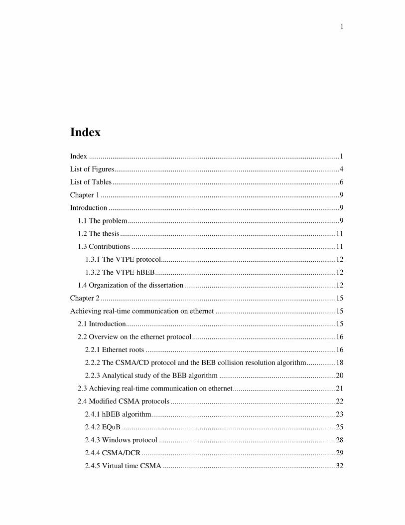
Index
Index .................................................................................................................................1
List of Figures....................................................................................................................4
List of Tables .....................................................................................................................6
Chapter 1 ...........................................................................................................................9
Introduction .......................................................................................................................9
1.1 The problem.............................................................................................................9
1.2 The thesis ...............................................................................................................11
1.3 Contributions .........................................................................................................11
1.3.1 The VTPE protocol..........................................................................................12
1.3.2 The VTPE-hBEB.............................................................................................12
1.4 Organization of the dissertation ..............................................................................12
Chapter 2 .........................................................................................................................15
Achieving real-time communication on ethernet ..............................................................15
2.1 Introduction............................................................................................................15
2.2 Overview on the ethernet protocol..........................................................................16
2.2.1 Ethernet roots ..................................................................................................16
2.2.2 The CSMA/CD protocol and the BEB collision resolution algorithm...............18
2.2.3 Analytical study of the BEB algorithm ............................................................20
2.3 Achieving real-time communication on ethernet.....................................................21
2.4 Modified CSMA protocols .....................................................................................22
2.4.1 hBEB algorithm...............................................................................................23
2.4.2 EQuB ..............................................................................................................25
2.4.3 Windows protocol ...........................................................................................28
2.4.4 CSMA/DCR....................................................................................................29
2.4.5 Virtual time CSMA .........................................................................................32
2
2.5 Token passing technique ........................................................................................33
2.5.1 RETHER.........................................................................................................34
2.5.2 RT-EP: Real-Time Ethernet Protocol...............................................................35
2.5.3 Other ...............................................................................................................37
2.6 Virtual token passing..............................................................................................37
2.7 Time division multiple access – TDMA .................................................................41
2.7.1 The MARS bus................................................................................................41
2.7.2 Variable bandwidth allocation scheme.............................................................42
2.8 Master/slave techniques..........................................................................................43
2.8.1 FTT-Ethernet protocol .....................................................................................44
2.8.2 ETHERNET Powerlink ...................................................................................45
2.9 Switched ethernet ...................................................................................................47
2.9.1 EDF scheduled switch .....................................................................................49
2.9.2 EtheReal..........................................................................................................51
2.10 Recent advances ...................................................................................................53
2.11 Conclusion ...........................................................................................................55
Chapter 3 .........................................................................................................................57
Virtual Token Passing Ethernet –VTPE ...........................................................................57
3.1 Introduction............................................................................................................57
3.2 The classic virtual token-passing approach .............................................................58
3.2.1 The VTPE format frame ..................................................................................61
3.2.2 The VTPE parameters t1 and t2 ........................................................................63
3.2.3 VTPE real-time worst-case computation..........................................................64
3.2.4 Some experimental results ...............................................................................66
3.3. Adapting VTPE to support isochronous traffic ......................................................67
3.3.1 The bandwidth allocation scheme ....................................................................68
3.3.2 Timing analysis ...............................................................................................70
3.3.3 Example ..........................................................................................................73
3.3.4 Adapting the classic VTPE frame ....................................................................75
3.4. Conclusions...........................................................................................................75
Chapter 4 .........................................................................................................................77
The VTPE-hBEB Protocol ...............................................................................................77

3
4.1 Introduction............................................................................................................77
4.2 The VTPE-hBEB protocol......................................................................................79
4.2.1 VTPE-hBEB topology .....................................................................................79
4.2.2 VTPE-hBEB protocol......................................................................................79
4.2.3 Timing analysis ...............................................................................................81
4.2.4 Adapting the VTPE-hBEB proposal ................................................................84
4.3 Conclusions............................................................................................................88
Chapter 5 .........................................................................................................................89
VTPE and VTPE-hBEB Implementations ........................................................................89
5.1 Introduction............................................................................................................89
5.2 Implementation based on single ethernet controller ................................................90
5.2.1 System architecture based on single ethernet controller....................................90
5.2.2 Hardware of master based on single controller.................................................91
5.2.3 The VTPE stack architecture ...........................................................................93
5.2.4 Using VTPE with application program ............................................................97
5.3 Implementation based on a dual ethernet controller architecture .............................98
5.3.1 The dual ethernet controller architecture ..........................................................98
5.3.2 Hardware of master based on dual ethernet controller architecture.................100
5.3.3 VTPE or VTPE-hBEB software for the dual ethernet controllers architecture 102
5.3.4 Using VTPE with an application program......................................................107
5.4 Implementation based on an IP core .....................................................................108
5.5 Conclusions..........................................................................................................110
Chapter 6 .......................................................................................................................113
Timing Behavior and Validation of VTPE and VTPE-hBEB..........................................113
6.1 Introduction..........................................................................................................113
6.2 Timing behavior of VTPE in the implementation based on single controller.........114
6.3 Timing behavior of VTPE in the implementation based on the dual controller
architecture ................................................................................................................116
6.4 Demonstration system for validation of VTPE-hBEB...........................................121
6.4.1 The Evaluation setup .....................................................................................124
6.5 Timing analysis ....................................................................................................128
6.6 Results .................................................................................................................132
4
6.6.1 Unloaded network .........................................................................................133
6.6.2 Full loaded ethernet .......................................................................................135
6.7 Conclusions..........................................................................................................139
Chapter 7 .......................................................................................................................141
Conclusions and Future Works ......................................................................................141
7.1 Thesis validation ..................................................................................................142
7.2 Future work..........................................................................................................144
Bibliography..................................................................................................................147
List of Figures
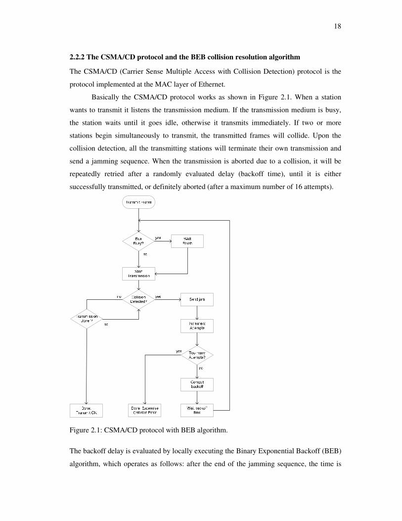
Figure 2.1: CSMA/CD protocol with BEB algorithm. ......................................................18
Figure 2.2: Chanel Efficiency...........................................................................................21
Figure 2.3: Control Flow Summary – hBEB.....................................................................23
Figure 2.4: Black burst contention resolution mechanism.................................................27
Figure 2.5: Resolving collisions with the Windows protocol. ...........................................29
Figure 2.6: Example of tree search with CSMA/DCR. .....................................................31
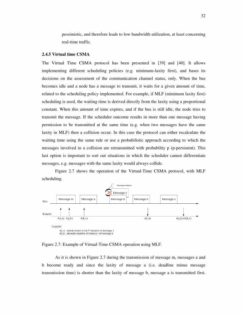
Figure 2.7: Example of Virtual-Time CSMA operation using MLF..................................32
Figure 2.8: Sample network configuration for RETHER. .................................................35
Figure 2.9: Concepts of message cycle, token holding time (H), slave's turnaround time,
master's reaction time (ρ), idle token time (σ) and token passing time (τ) in P-NET. .........39
Figure 2.10: Byte structure in a P-NET frame. .................................................................40
Figure 2.11: Frame of P-NET...........................................................................................40
Figure 2.12: The structure of a TDMA frame. ..................................................................42
Figure 2.13: FTT-Ethernet traffic structure.......................................................................44
Figure 2.14: Powerlink cycle structure. ............................................................................46
Figure 2.15: Switch internal architecture. .........................................................................48
Figure 2.16: System architecture. .....................................................................................50
Figure 2.17: Connection set-up procedure in the EtheReal architecture. ...........................52
Figure 3.1: The Virtual Token-passing in a VTPE system. ...............................................58
Figure 3.2: VTPE flowchart. ............................................................................................60
5
Figure 3.3: Virtual Token-Passing Ethernet MAC frame. .................................................61
Figure 3.4: VTPE frame format........................................................................................62
Figure 3.5: VTPE real-time behavior................................................................................64
Figure 3.6: State machine of the bandwidth allocation scheme. ........................................69
Figure 3.7: New VTPE frame...........................................................................................75
Figure 4.1: Heterogeneous Ethernet environment. ............................................................77
Figure 4.2: VTPE-hBEB Topology. .................................................................................79
Figure 4.3: Control Flow Summary – VTPE-hBEB..........................................................80
Figure 4.4: Collision scenario solved by the hBEB collision resolution algorithm. ...........82
Figure 4.5: VTPE-hBEB token holding time. ...................................................................84
Figure 4.6: VTPE flowchart for a dual Ethernet controller implementation. .....................86
Figure 5.1: VTPE system architecture ..............................................................................90
Figure 5.2: Experimental setup.........................................................................................91
Figure 5. 3: Hardware of a VTPE master..........................................................................92
Figure 5. 4:VTPE master software architecture ................................................................93
Figure 5. 5: Path of application to the VTPE ....................................................................96
Figure 5.6: Dual Ethernet controller architecture. .............................................................99
Figure 5. 7:Experimental setup for dual Ethernet controller architecture.........................100
Figure 5. 8: Hardware of master based on dual Ethernet controllers. ..............................101
Figure 5. 9:VTPE or VTPE-hBEB based on dual Ethernet controller architecture. .........103
Figure 5. 10: VTPE or VTPE-hBEB for dual Ethernet controller architecture. ...............103
Figure 5. 11: Software for the second part of the dual Ethernet Controller architecture...107
Figure 5. 12:VTPE IP core block diagram......................................................................109
Figure 6. 1: t1 (µs) x bus utilisation (%)..........................................................................116
Figure 6. 2: VTPE transmission scenario in the dual Ethernet controller architecture......119
Figure 6. 3: Testing a dedicated MIDI link. ....................................................................121
Figure 6. 4: MIDI to RS232 level logic adaptation. ........................................................122
Figure 6. 5: MIDI to VTPE-hBEB link...........................................................................122
Figure 6.6: MIDI to VTPE-hBEB link with Ethernet traffic injection. ............................123
6
Figure 6. 7: Evaluation test-bed......................................................................................124
Figure 6. 8: Application sub-node flowchart...................................................................125
Figure 6. 9: Application sub-node ISRs flowchart. .........................................................126
Figure 6. 10: Delay Measurement System. .....................................................................127
Figure 6. 11: Ethereal capture – unloaded network. ........................................................133
Figure 6.12: Delay histogram - unloaded network. .........................................................134
Figure 6.13: TRT histogram - unloaded network. ...........................................................134
Figure 6.14: Ethereal capture – fully loaded network......................................................136
Figure 6.15: Delay histogram – fully loaded network. ....................................................136
Figure 6. 16: TRT histogram – fully loaded network. .....................................................137
Figure 6. 17: Worst case TRT time line..........................................................................138
List of Tables
Table 2.1: Tree search example (contending sequence). ...................................................31
Table 3.1: Tasks on received frame. .................................................................................64
Table 3.2: VTPE experimental results. .............................................................................66
Table 3.3: Bandwidth allocation table for the example of Figure 3.6. ...............................70
Table 3.4: Bandwidth allocation table for an example with 5 nodes..................................73
Table 3.5:Real-time analysis results for the example of Table 3.4 ....................................75
Table 4.1: Maximum delay to start transferring a message in the hBEB algorithm. ..........82
Table 5. 1:Set of functions for RTL8019AS initialisation. ................................................95
Table 5. 2:VTPE Layer. ...................................................................................................97
Table 5. 3: Set of functions for CS8900A-CQ initialisation. ...........................................105
Table 5. 4: Set of functions for the VTPE or VTPE-hBEB Layer. ..................................105
Table 6.1: t1 and bus utilisation in the implementation based on a single Ethernet controller.
......................................................................................................................................115
Table 6. 2: Arbitration time on the dual Ethernet controller architecture.........................118
7
Table 6. 3: Unloaded network – summary. .....................................................................135
Table 6.4: Fully loaded network – summary...................................................................138

8

9
Chapter 1
Introduction
1.1 The problem
Distributed Computer-Control Systems (DCCS) are widely disseminated, appearing in
applications ranging from automated process and manufacturing control to automotive,
avionics and robotics. Many of these applications have real-time nature, i.e., pose stringent
constraints to the properties of the underlying control systems, which arise from the need
to provide predictable behaviour during extended time periods. Depending on the
particular type of application, failure to meet these constraints can cause important
economic losses or can even put human life in risk [1].
Nowadays, the quantity and functionality of microprocessor-based nodes in modern
DCCS have been increasing steadily [2]. This evolution has been motivated by new classes
of more resource demanding applications, such as multimedia applications (e.g. machine
vision), as well as by the trend to use large numbers of simple interconnected processors,
instead of few powerful ones [3], encapsulating each functionality in one single processor
[3]. Consequently, the amount of information that must be exchanged among the network
nodes has also increased dramatically over the last years and it is now reaching the limits
that are achievable using traditional fieldbuses [4], e.g. CAN, WorldFIP, PROFIBUS.
Therefore, other alternatives are required to support higher bandwidth demands
while keeping the main requirements of a real-time communication system: predictability,
timeliness, bounded delays and jitter.
Well-known networks, such as FDDI and ATM, have been extensively analysed for
both hard and soft real-time communication systems [4]. However, due to high complexity,

10
high cost, lack of flexibility and interconnection capacity, they have not gained general
acceptance for the use at the field level [4].
Similar efforts have been done with Ethernet, trying to take advantage of the
availability of cheap silicon, easy integration with Internet, clear path for future
expandability, and compatibility with networks used at higher layers in the factory
structure [5]. However, its standardized non-deterministic arbitration mechanism
(CSMA/CD) prevents its direct use at field level, at least for hard real-time
communications. Despite of this, there are many different approaches for achieving real-
time behaviour on Ethernet.
The techniques that have been used to achieve deterministic message transmission
on Ethernet are the well-known medium access control techniques for shared broadcast
networks such as Modified CSMA protocols, Time Division Multiple Access – TDMA,
Token-passing, Master/slave technique, and Switched Ethernet.
Since roughly one decade ago that the interest on using Ethernet switches has been
growing as a means to improve global throughput, traffic isolation and to reduce the
impact of the non-deterministic features of the original CSMA/CD arbitration mechanism.
However a common misconception is that the use of switches, due to the elimination of
collisions, is enough to enforce real-time behaviour in Ethernet networks, but this is not
true in the general case.
Despite of the recent proposals consisting in using switched Ethernet to replace
fieldbuses in control and factory automation, the interest on shared Ethernet is not over,
yet, either for applications requiring frequent multicasting, in which case the benefits of
using switches are substantially reduced, as well as for applications requiring precise
control of transmission timing, such as high speed servoing (Almeida and Pedreiras [6]).
Solving the collision problem however is only part of a useful shared Ethernet
solution to field level application. There are many other important requirement that a real-
time Ethernet solution must have, or at least, that it is desirable to have. For example some
of those are the introduction of operational flexibility, like to add and to remove nodes, to
have an online bandwidth allocation scheme, to have an efficient support of multicast
messages, and to be fault tolerant.
Nowadays there are many approaches to achieve real-time on shared Ethernet, but
it is interesting to notice that such approaches either require specialized hardware, or just

11
provide statistical timeliness guarantees, or are bandwidth or response-time inefficient, or
are inflexible concerning the properties of the network traffic as well as the traffic
scheduling policy, or finally, they are costly in terms of processing power and memory
requirements. Also, recent proposals such as hBEB [9] limit the number of real-time nodes
to just a single transmission station which is unacceptable for automation applications.
Thus they are not well suited for use in small sensors, actuators and controllers with
communications capability. So there is a need to find Ethernet deterministic solutions, so
that it becomes possible to take profit of its higher data-communication capacity to
interconnect sensors, controllers and actuators at the field level.
This thesis discourses about a new real-time Ethernet solution based on the virtual
token-passing in order to override the destructive and non-deterministic CSMA/CD
medium access arbitration mechanism of Ethernet. Virtual token-passing technique is a
real-time bus arbitration mechanism especially suitable for shared networks which use
small processing power processors in most of the nodes.
1.2 The thesis
This thesis presents a proposal and the development of the Virtual Tokenpassing Ethernet
(VTPE), a new real-time implementation to support real-time traffic on shared Ethernet,
and the VTPE-hBEB protocol, an improvement of VTPE to support real-time
communication in unconstrained shared Ethernet, i.e., an environment comprised of an
unlimited number of Ethernet standard stations and real-time stations (hBEB).
EQuB and hBEB, according our best knowledge are the unique solutions that
provide traffic separation, allowing real-time devices to coexist with standard Ethernet
devices in the same network segment.
1.3 Contributions
Two general contributions of this thesis are summarized in the following subsections. The
first one is the proposal and development of the VTPE protocol, and the second one is the
VTPE-hBEB protocol a variant of VTPE, to support real-time communication in
unconstraint shared Ethernet.

12
1.3.1 The VTPE protocol
The VTPE [7] is a real-time Ethernet approach based on implicit token rotation (virtual
token passing) like the one used in the P-NET fieldbus protocol [8]. The virtual token-
passing approach is a simple and efficient technique suitable for shared bus networks,
especially when small processing power processors are used as CPUs.
The following goals have been established to develop VTPE:
• Support on the same bus of slow and cheap devices based in microcontrollers, as
well as more demanding devices integrating powerful processors;
• Low processing overhead in order to be implemented in microcontrollers with low
processing power;
• Hardware based in COTs components;
• Online bandwidth allocation scheme
• Support for hBEB protocol to work as multi-node (VTPE-hBEB protocol);
• Efficient support of multicast messages;
1.3.2 The VTPE-hBEB
The VTPE-hBEB protocol, as the name indicates, is an implementation of VTPE over
hBEB protocol. hBEB is a real-time shared Ethernet protocol proposed in [9] which main
advantage is to support real-time traffic separation on a shared Ethernet bus. However
hBEB has a disadvantage: it is single-node, i.e., it just allows one node with real-time
privileges. hBEB lacks a mechanism to support multi-node implementation and the VTPE
is indicated as the principal bus arbitration mechanism to solve this problem. So the VTPE-
hBEB is other important contribution of this thesis.
1.4 Organization of the dissertation
In order to support the thesis previously stated this dissertation is organized in the
following chapters.
Chapter 2 - Presents a background on the Ethernet protocol and discusses the main
Ethernet approaches proposed for real-time communication on shared Ethernet networks
throughout Ethernet evolution. Chapter 2 also presents some discussions and approaches
for real-time communication on switched Ethernet considering its current popularity.
However it is focused on shared Ethernet that is the context of this thesis.

13
Chapter 3 – Presents the Virtual Token-Passing Ethernet protocol - VTPE. In the Chapter
3 are presented the VTPE classic approach similar to the P-NET protocol and an adaptation
of VTPE in order to support isochronous traffic.
Chapter 4 - Presents the VTPE-hBEB protocol. VTPE-hBEB is an improvement of VTPE
aimed for real-time communication on shared Ethernet. VTPE-hBEB allows the
coexistence of real-time devices as well as standards Ethernet devices in the same network
segment.
Chapter 5 - Presents the implementations of VTPE and VTPE-hBEB protocol.
Implementation aspects as well as software and hardware are presented and discussed.
Chapter 6 - Presents the experimental results obtained for both implementations.
Chapter 7 - This chapter presents the conclusions and future works. As future works are
proposed the implementation of VTPE and its variants on IP cores and a new version of
VTPE for power line communication.

14
15
Chapter 2
Achieving real-time communication on ethernet
2.1 Introduction
Ethernet is the most frequently used wired local area network technology today. The Main
factors that favour the use of the Ethernet protocol are [6]:
• It is cheap, due to mass production;
• Integration with Internet is easy (TCP/IP stacks over Ethernet are widely available,
allowing the use of application layer protocols such as FTP, HTTP and so on);
• Steady increases on the transmission speed have happened in the past, and are
expected to occur in the near future;
• Due to its inherent compatibility with the communication protocols used at higher
levels, the information exchange with the plant level becomes easier;
• The bandwidth made available by existing fieldbuses is insufficient to support
some recent developments, like the use of multimedia (e.g. machine vision) at the
field level;
• Availability of technicians familiar with this protocol;
• Wide availability of test equipment from different sources;
• Mature technology, well specified and with equipment available from many
sources, without incompatibility issues.
However Ethernet does not fulfil some fundamental requirements that are expected from a
communication protocol operating at the field level. In particular, the destructive and non-
deterministic arbitration mechanism has been regarded as the main obstacle faced by
Ethernet concerning this applications domain. The answer to this concern is the use of

16
switched Ethernet, which allows bypassing the native CSMA/CD arbitration mechanism.
In these cases, provided that a single network interface card (NIC) is connected to each
port, and the operation is full duplex, no collisions occur. However, just avoiding collisions
does not make Ethernet deterministic: for example, if a burst of messages destined to a
single port arrive at the switch in a given time interval, they must be serialized and
transmitted one after the other. If the arriving rate is greater that the transmission rate,
buffers will be exhausted and messages will be lost. Therefore, even with switched
Ethernet, some kind of higher-level coordination is required. Moreover, bounded
transmission delay is not the only requirement of a fieldbus, some other important factors
commonly referred to in the literature are: temporal consistency indication, precedence
constraints, efficient handling of periodic and sporadic traffic. Clearly, Ethernet, even with
switches, does not provide answers to all these demands [6].
This chapter presents and discusses the state of the art of the main real-time
protocols based on Ethernet, proposed during Ethernet evolution. It is focused on shared
Ethernet. However, a brief overview on switched Ethernet is also presented, considering its
current popularity.
The remaining of this chapter is as follows: Section 2.2 presents an overview on the
Ethernet protocol. Section 2.3 presents the main medium access control techniques for
shared broadcast networks that are commonly used to guarantee real-time communication.
Section 2.4 to section 2.8 discusses each one of the medium access control techniques and
the main shared Ethernet real-time approaches based on these techniques. Section 2.9
presents some discussions and techniques related to switched Ethernet and section 2.10
presents the recent advances in the Ethernet issues. Finally section 2.11 presents the
conclusions.
2.2 Overview on the ethernet protocol
2.2.1 Ethernet roots
Ethernet was born about 30 years ago, invented by Bob Metcalfe at the Xerox’s Palo Alto
Research Center. Its initial purpose was to connect two products developed by Xerox: a
personal computer and a brand new laser printer. Since then, this protocol has evolved in
many ways. For instance, concerning the transmission speed, it has grown from the
17
original 2.94Mbps to 10Mbps [10] [11] [12] [13] [14] then to 100Mbps [15] and more
recently to 1Gbps [16] and 10Gbps [17]. Concerning physical medium and network
topology, Ethernet also has evolved: it started by a bus topology based firstly on thick
coaxial cable [11]and afterwards on thin coaxial cable [12]. In the mid 80’s a more
structured and fault-tolerant approach, based on a star topology, was standardized [13],
running however only at 1Mbps. In the beginning of the 90’s an improvement of this latter
technology was standardized [14], running at 10Mbps over category 5 unshielded twisted
pair cable.
Along this way, two fundamental properties have been kept unchanged:
• Single collision domain, that is, frames are broadcast on the physical medium and
all the network interface cards (NIC) connected to it receive them;
• The arbitration mechanism, which is called Carrier Sense Multiple Access with
Collision detection (CSMA/CD).
The use of a single broadcast domain and the CSMA/CD arbitration mechanism has
created a bottleneck when facing highly loaded networks: above a certain threshold, when
the submitted load increases the throughput of the bus decreases, a phenomenon referred to
as thrashing. In the beginning of the 90’s, the use of switches in place of hubs has been
proposed as an effective way to deal with thrashing. A switch creates a single collision
domain for each of its ports. If a single node is connected to each port, collisions never
actually occur unless they are created on purpose, e.g. for flow control. Switches also keep
track of the addresses of the NICs connected at each port by inspecting the source address
in the incoming messages. This allows forwarding incoming messages directly to the
respective outgoing ports according to the respective destination address, a mechanism
generally known as forwarding. When a match between a destination address and a port
cannot be established, the switch forwards the respective message to all ports, a process
commonly referred to as flooding. The former mechanism, forwarding, allows a higher
degree of traffic isolation so that each NIC receives the traffic addressed to it, only.
Moreover, since each forwarding action uses a single output port, several of these actions
can be carried out in parallel, resulting in multiple simultaneous transmission paths across
the switch and, consequently, in a significant increase in the global throughput.
18
2.2.2 The CSMA/CD protocol and the BEB collision resolution algorithm
The CSMA/CD (Carrier Sense Multiple Access with Collision Detection) protocol is the
protocol implemented at the MAC layer of Ethernet.
Basically the CSMA/CD protocol works as shown in Figure 2.1. When a station
wants to transmit it listens the transmission medium. If the transmission medium is busy,
the station waits until it goes idle, otherwise it transmits immediately. If two or more
stations begin simultaneously to transmit, the transmitted frames will collide. Upon the
collision detection, all the transmitting stations will terminate their own transmission and
send a jamming sequence. When the transmission is aborted due to a collision, it will be
repeatedly retried after a randomly evaluated delay (backoff time), until it is either
successfully transmitted, or definitely aborted (after a maximum number of 16 attempts).
Figure 2.1: CSMA/CD protocol with BEB algorithm.
The backoff delay is evaluated by locally executing the Binary Exponential Backoff (BEB)
algorithm, which operates as follows: after the end of the jamming sequence, the time is

19
divided into discrete slots, whose length is equal to the slot time1. The backoff time is
given by tbackoff = r x T, where r is a random integer in the range 120 −≤≤ kr , k is the smaller
of n or 10 (n is the number of retransmission attempts) and T is the slot time in seconds.
This means that the station will wait between 0 and 2k–1 slot times. After 10 attempts, the
waiting interval is fixed at 1023 slot times, and finally, after 16 attempts, the transmission
is discarded.
The CSMA/CD protocol seems to have a random queue service discipline, i.e., the
message to be transferred after a successful transmission seems to be randomly chosen
among the N hosts with ready messages. However, Christensen [18] demonstrated that the
BEB algorithm imposes a last come first serve policy, as a station with the more recently
queued packet, will have a higher probability for the acquisition of the medium.
Another particularity of the CSMA/CD protocol is the Packet Starvation Effect.
Wheten et al. [19] demonstrated that, in heavily loaded networks, an older packet will have
a smaller probability to be transferred than a newer one. For example: consider that 2
stations have packets ready to be transmitted (station1 and station2), which will be
transmitted at approximately the same time; a collision will occur and then both stations
will backoff during a randomly selected delay between 0 and 2n-1 slot times, where n is the
number of previous collisions. In the first collision resolution interval, if station1 waits 0
slot times and station2 waits 1 slot time, station1 will transmit its packet while station2 will
wait. Supposing that station1 has other packets to be transferred, then, in the following
collision, the backoff time of station1 will be 0 or 1, and the backoff time of the station2
will be 0, 1, 2 or 3. Therefore, station1 will have a higher transmission probability. Such
Packet Starvation Effect will occur whenever a station has a sequence of packets to be
consecutively transferred, if the network interface adapter is able to effectively contend for
the network access at the end of every transmitted frame. Otherwise, another station will
acquire the transmission medium.
1 For Ethernet and Fast Ethernet (10/100 Mbps) networks, one slot time is the time required for transmitting
the minimum frame size (512 bits), that is, respectively, 51.2 and 5.12 µsec. For Gigabit Ethernet (1Gbps),
one slot time corresponds to the transmission time of 4096 bits.
20
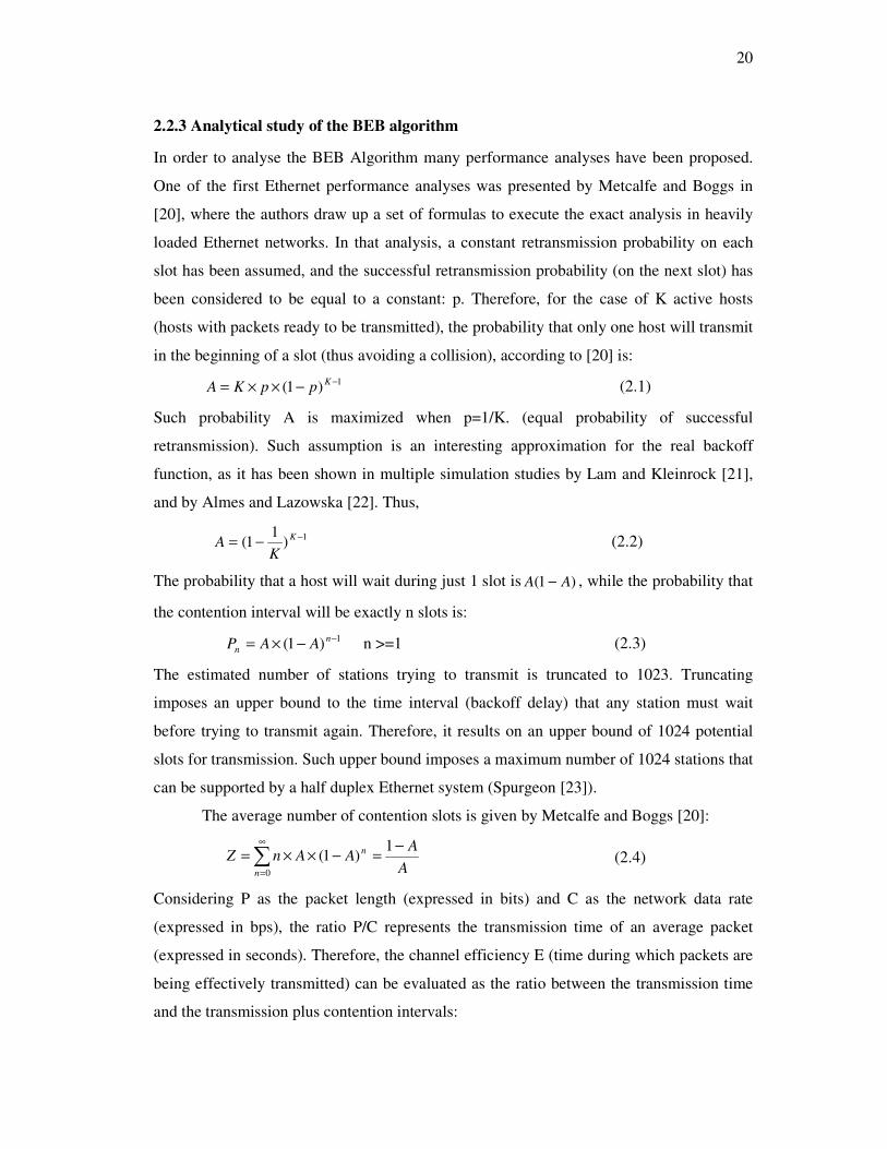
2.2.3 Analytical study of the BEB algorithm
In order to analyse the BEB Algorithm many performance analyses have been proposed.
One of the first Ethernet performance analyses was presented by Metcalfe and Boggs in
[20], where the authors draw up a set of formulas to execute the exact analysis in heavily
loaded Ethernet networks. In that analysis, a constant retransmission probability on each
slot has been assumed, and the successful retransmission probability (on the next slot) has
been considered to be equal to a constant: p. Therefore, for the case of K active hosts
(hosts with packets ready to be transmitted), the probability that only one host will transmit
in the beginning of a slot (thus avoiding a collision), according to [20] is:
1)1( −−××=
KppKA (2.1)
Such probability A is maximized when p=1/K. (equal probability of successful
retransmission). Such assumption is an interesting approximation for the real backoff
function, as it has been shown in multiple simulation studies by Lam and Kleinrock [21],
and by Almes and Lazowska [22]. Thus,
1)1
1( −−= K
KA (2.2)
The probability that a host will wait during just 1 slot is )1( AA − , while the probability that
the contention interval will be exactly n slots is:
1)1( −−×= n
n AAP n >=1 (2.3)
The estimated number of stations trying to transmit is truncated to 1023. Truncating
imposes an upper bound to the time interval (backoff delay) that any station must wait
before trying to transmit again. Therefore, it results on an upper bound of 1024 potential
slots for transmission. Such upper bound imposes a maximum number of 1024 stations that
can be supported by a half duplex Ethernet system (Spurgeon [23]).
The average number of contention slots is given by Metcalfe and Boggs [20]:
A
AAAnZ n
n
−=−××=∑
∞
=
1)1(
0
(2.4)
Considering P as the packet length (expressed in bits) and C as the network data rate
(expressed in bps), the ratio P/C represents the transmission time of an average packet
(expressed in seconds). Therefore, the channel efficiency E (time during which packets are
being effectively transmitted) can be evaluated as the ratio between the transmission time
and the transmission plus contention intervals:

21
( )TZCP
CPE
×+= (2.5)
where Z×T represents the average acquisition time before effectively transmitting (T is the
slot time in seconds). Figure 2.2 illustrates the “channel efficiency” in heavily loaded
networks, assuming a 10Mbps Ethernet network (C=10 Mbps; T=51.2ms).
Figure 2.2: Chanel Efficiency.
According to Boggs et al. [24], one of the most widely accepted Ethernet myths is that it
saturates at an offered load of 37%. Such assertion is well founded when dealing with short
sized frames and a significant number of hosts. However, for longer frames, the channel
efficiency is significantly improved. Schoch and Hupp [25] presented measurements
results indicating that for 4096 bit frames and small number of hosts, the channel
utilization approaches 97%; however, for small packets and larger number of hosts the
utilization approaches 1/e, that is, approaches the 37% bound. These results are consistent
with the Metcalfe and Boggs analysis [20], as it can be observed in the channel efficiency
results represented in Figure 2.2.
2.3 Achieving real-time communication on ethernet
In the quest for real-time communication over Ethernet several approaches have been
developed and used. Many of them override the Ethernet CSMA/CD medium access
control by setting an upper transmission control layer that eliminates, or at least reduces,
the occurrence of collisions at the medium access. Other approaches propose the

22
modification of the CSMA/CD medium access control layer so that collisions either occur
seldom or when they do, the collision resolution is deterministic and takes a bounded
worst-case time.
Moreover, some approaches support such deterministic reasoning on the network
access delay while other ones allow a probabilistic characterization, only.
The solutions to make shared Ethernet real time are mainly based on the usual medium
access control techniques for shared broadcast networks. For the sake of clarity, they are
classified and presented as follows in the remainder of this chapter:
• Modified CSMA protocols;
• Token-passing;
• Virtual token passing;
• Time Division Multiple Access - TDMA;
• Master/slave techniques;
Switched Ethernet doesn’t enable the use of a shared Ethernet bus because the switch
creates a single collision domain. In spite of this large difference, Switched Ethernet is also
discussed, considering its current popularity.
2.4 Modified CSMA protocols
In this category the CSMA mechanism is adequately modified in order to improve the
temporal behaviour of the network (e.g. [26] [27] [28]). The result is still a fully distributed
arbitration protocol of the CSMA family (Carrier Sense, Multiple Access) that determines
when to transmit based on local information and on the current state of the bus, only.
There are two most common options, either sorting out collisions in a more
deterministic way than the Ethernet original BEB mechanism (truncated Binary
Exponential Backoff) or reducing the probability of collisions. This section presents five
modified CSMA/CD protocols, the first four, i.e., hBEB algorithm, EQuB, Windows
protocol and the CSMA/DCR follow the first option. The last one, that is, the Virtual Time
CSMA follows the second option by implementing a type of CSMA/CA (Collision
Avoidance) that delays message transmissions according to a temporal parameter.

23
2.4.1 hBEB algorithm
Moraes and Vasques [9] proposed the “high priority Binary Exponential Backoff (hBEB)”
collision resolution algorithm. The main advantage of hBEB is allowing Ethernet standard
devices to coexist with one hBEB modified station. As a consequence, it becomes possible
the implementation of traffic separation policies, which are the foundation for the support
of real-time communication, in heterogeneous Ethernet environments.
A station implementing the hBEB algorithm has the same operating behavior of
BEB algorithm, except for the backoff delay, which is set to 0. In such case, an hBEB
station starts immediately to transmit after the end of the jamming sequence. This behavior
guarantees the highest transmitting probability to the hBEB station, in a shared Ethernet
segment with multiple BEB stations. The hBEB station will always try to transmit its
frame in the first available slot after the jamming sequence, while all the other stations
implementing the BEB algorithm will wait between 0 and 2n-1 slot times, where n is the
number of collision resolution rounds. Figure 2.3 summarize the dynamic behavior of the
CSMA/CD protocol with the hBEB collision resolution algorithms.
Transmit Frame
BusBusy?
ColisionDetect
Start Transmission
W aitFinish
yes
yes
no
TransmissionDone?
no
send jam
Done:TransmitOk
yes
IncrementAttempts
too manyattempts?
Done:ExcessiveCollision
Error
yes
no
no
Figure 2.3: Control Flow Summary – hBEB.
The hBEB collision resolution algorithm is therefore able to impose real-time
traffic separation, as the traffic generated by the hBEB station will always be transferred
before the traffic generated by the other stations. Therefore, this algorithm is adequate to
support real-time communications in shared Ethernet segments, as long as all the real-time
traffic in the network is generate by the hBEB station. According to Moraes and Vasques
this behavior is highly adequate for real-time video/voice transferring applications in
24
legacy shared Ethernet networks. By simply plugging a notebook computer with the
modified hardware to the shared Ethernet segment, it becomes possible to transfer traffic at
a higher priority than the traffic generated by all the other stations.
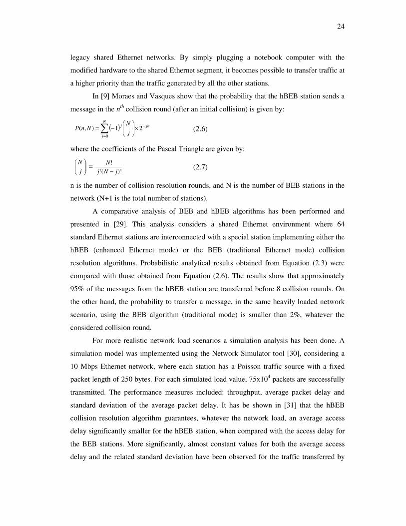
In [9] Moraes and Vasques show that the probability that the hBEB station sends a
message in the nth collision round (after an initial collision) is given by:
( )∑=
−×
−=
N
j
jnj
j
NNnP
0
21),( (2.6)
where the coefficients of the Pascal Triangle are given by:
j
N =
)!(!
!
jNj
N
− (2.7)
n is the number of collision resolution rounds, and N is the number of BEB stations in the
network (N+1 is the total number of stations).
A comparative analysis of BEB and hBEB algorithms has been performed and
presented in [29]. This analysis considers a shared Ethernet environment where 64
standard Ethernet stations are interconnected with a special station implementing either the
hBEB (enhanced Ethernet mode) or the BEB (traditional Ethernet mode) collision
resolution algorithms. Probabilistic analytical results obtained from Equation (2.3) were
compared with those obtained from Equation (2.6). The results show that approximately
95% of the messages from the hBEB station are transferred before 8 collision rounds. On
the other hand, the probability to transfer a message, in the same heavily loaded network
scenario, using the BEB algorithm (traditional mode) is smaller than 2%, whatever the
considered collision round.
For more realistic network load scenarios a simulation analysis has been done. A
simulation model was implemented using the Network Simulator tool [30], considering a
10 Mbps Ethernet network, where each station has a Poisson traffic source with a fixed
packet length of 250 bytes. For each simulated load value, 75x104 packets are successfully
transmitted. The performance measures included: throughput, average packet delay and
standard deviation of the average packet delay. It has be shown in [31] that the hBEB
collision resolution algorithm guarantees, whatever the network load, an average access
delay significantly smaller for the hBEB station, when compared with the access delay for
the BEB stations. More significantly, almost constant values for both the average access
delay and the related standard deviation have been observed for the traffic transferred by
25
the hBEB station. This is a very important result, as it forecasts a predictable
communication delay when supporting real-time communications.
The authors of hBEB showed by simulation analysis that the hBEB traffic must be
tightly controlled, as it has a high interference level over the non-real-time traffic [32],
otherwise, if the load generated by the hBEB station is not closely controlled, the standard
Ethernet stations may experience extended access delays.
A probabilistic timing analysis of hBEB was presented in [33] for two cases.
Firstly, the analytical study for a heavily loaded network scenario shows that the maximum
access delay for 95% of the messages is smaller than 1,86ms. Secondly, for more realistic
load scenarios (intermediate load cases), the simulation analysis shows that the maximum
access delay for 98% of the messages is always smaller than 1ms. More importantly, it
shows a nearly constant message transfer jitter, which is one order of magnitude smaller
than the maximum access delay for 98% of the messages. Also it is shown that concerning
the probability of a message frame being discarded by the hBEB algorithm, for the heavily
loaded network scenario, such probability is always smaller than 2x10⁻³ and for more
realistic load scenarios, the simulation analysis never detected any discarded frame.
According to Moraes and Vasques these are important results, as they forecast a
predictable communication delay when supporting real-time communications with the
hBEB collision resolution algorithm. These results are also consistent with the claim that
the hBEB algorithm is adequate to support most part of the soft real-time applications.
The main drawback of the hBEB algorithm is that it allows at most one hBEB
station per shared Ethernet segment. However, this mechanism has been extended by the
use of a virtual token passing procedure in [34], allowing multiple hBEB (real-time)
stations to coexist with multiple standard Ethernet stations in the same network segment,
and still imposing a higher priority for the transfer of privileged traffic. This new version
of hBEB is named Virtual Token Passing over hBEB or VTPE-hBEB for short and is
presented in Chapter 4.
2.4.2 EQuB
Sobrinho and Krishnakumar [35] propose the EQuB protocol, which allows achieving
predictable behaviour on shared Ethernet networks. EQuB consists on an overlay
mechanism to the native CSMA/CD while providing privileged access to the former over

26
the latter, with a FCFS (First-Come-First-Served) access discipline between contending
real-time sources.
The collision resolution mechanism for real-time sources (EQuB hosts) requires the
disabling of the native exponential backoff mechanism of Ethernet and the transmission of
jamming sequences with pre-defined durations. Both features are configured in the
network interface card of the respective hosts. The underlying real-time traffic model
assumes that, during long intervals of time called sessions, real-time hosts generate
continuously periodic streams of data to be transmitted over the network.
Collisions involving non-real-time hosts, only, are sorted out by the native
CSMA/CD mechanism of Ethernet. However, when real-time hosts participate in a
collision, they start transmitting a jamming signal, as specified in the Ethernet MAC
protocol, but with duration different from the specified 32 bit times. These crafted
jamming signals are called black bursts and their maximum duration is set proportionally
to the time a given host has been waiting to transmit a given message, i.e. the duration of
the collision resolution process. During the transmission of a black burst, the bus state is
continuously monitored. If, at some moment, a real-time host contending for the bus
detects that no other nodes are sending black bursts, it infers that itself is the host having
the oldest ready message (highest priority according to FCFS), subsequently aborts the
transmission of its own black burst and immediately after it transmits the data message. If
a real-time host transmits its black burst completely and still feels the bus jammed it infers
that other hosts having longer black bursts, and consequently having a longer waiting
times, are also disputing the bus. In these circumstances the host relinquishes the bus
access, waiting for it to become idle for the duration of an IFS. At this time the black burst
duration is recomputed, to reflect the increased waiting time.
Figure 2.4 illustrates the mechanism explained before. Two hosts have one real-
time message each, 1 and 2, scheduled for transmission at instants t0 and t1, respectively,
while a third data message is being transmitted (Figure 2.4). Since both hosts feel the bus
busy, they wait for the end of the message transmission and for the IFS, which occurs at
instant t3. According to EQuB, both nodes attempt to transmit their message at time t3 but
feel a collision and start the transmission of black bursts (t4). Since message 2 has a shorter
waiting time than message 1, its black burst is completely transmitted, terminating at
instant t5, and the respective host backs-off, waiting for the bus to become idle again,
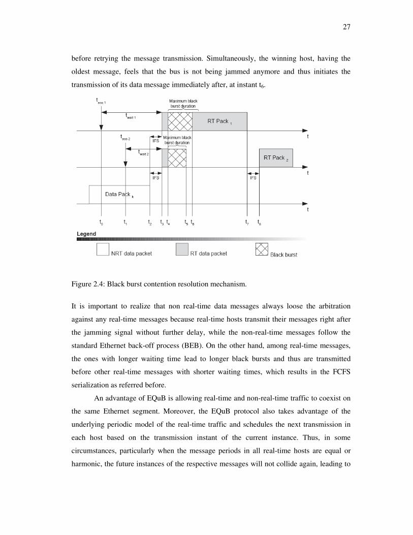
27
before retrying the message transmission. Simultaneously, the winning host, having the
oldest message, feels that the bus is not being jammed anymore and thus initiates the
transmission of its data message immediately after, at instant t6.
Figure 2.4: Black burst contention resolution mechanism.
It is important to realize that non real-time data messages always loose the arbitration
against any real-time messages because real-time hosts transmit their messages right after
the jamming signal without further delay, while the non-real-time messages follow the
standard Ethernet back-off process (BEB). On the other hand, among real-time messages,
the ones with longer waiting time lead to longer black bursts and thus are transmitted
before other real-time messages with shorter waiting times, which results in the FCFS
serialization as referred before.
An advantage of EQuB is allowing real-time and non-real-time traffic to coexist on
the same Ethernet segment. Moreover, the EQuB protocol also takes advantage of the
underlying periodic model of the real-time traffic and schedules the next transmission in
each host based on the transmission instant of the current instance. Thus, in some
circumstances, particularly when the message periods in all real-time hosts are equal or
harmonic, the future instances of the respective messages will not collide again, leading to

28
a high efficiency in bus utilization and to a round-robin service of real-time hosts.
However the implementation of EQuB requires special hardware because, according to our
best knowledge, there are no Ethernet controllers able to disable the backoff algorithm and
to perform timing control of the jamming sequence.
2.4.3 Windows protocol
The Windows protocol has been proposed both for CSMA/CD and token ring networks
[36]. Concerning the CSMA/CD implementation, the operation is as follows. The nodes on
a network agree on a common time interval (referred to as window). All nodes synchronize
upon a successful transmission, restarting the respective window. The bus state is used to
assess the number of nodes with messages to be transmitted within the window:
• If the bus remains idle, there are no messages to be transmitted in the window;
• If only one message is in the window, it will be transmitted;
• If two or more messages are within the window, a collision occurs.
Depending on the bus state, several actions can be performed:
• If the bus remains idle, the window duration is increased in all nodes;
• In the case of a collision, the time window is shortened in all nodes;
• In case of a successful transmission, the window is restarted and its duration is
kept as it is.
In the first two cases, the window duration is changed but the window is not
restarted. Moreover, the window duration varies between a maximum (initial) and
minimum values. Whenever there is a sufficiently long idle period in the bus, the window
will return to its original maximum length. If a new node enters dynamically in the system,
it may have instantaneous window duration different from the remaining nodes. This may
cause some perturbation during an initial period, with more collisions than expected.
However, as soon as an idle period occurs, all windows will converge to the initial length.
A probabilistic retry mechanism may also be necessary when the windows are shrunk to
their minimum and collisions still occur (e.g. when two messages have the same
transmission time).

29
Figure 2.5: Resolving collisions with the Windows protocol.
Figure 2.5 shows an example of the operation of the windows protocol used to
implement MLF message scheduling. The top axis represents the latest send times (lst) of
messages A, B and C. The lst of a message is the latest time instant by which the message
transmission must start so that the respective deadline is met. The first window (Step 1)
includes the lst of the three messages, thus leading to a collision. The intervenient nodes
feel the collision and the window is shrunk (Step 2). However, the lst of messages A and B
are still inside the window, causing another collision. In response to this event the window
size is shrunk again (Step 3). In this case only message A has its lst within the window,
leading to a successful transmission.
This method exhibits properties that are very similar to those of the previous
method (virtual time protocol). However, it is somewhat more efficient due to its adaptive
behaviour. In general, it also aims at soft real-time systems and uses a fully distributed
symmetrical approach with relatively low computational overhead. Notice that all message
parameters are relative and that there is no global time base again. Moreover, the protocol
efficiency is substantially influenced by the magnitude of variations in the window
duration, either when increasing or decreasing it.
2.4.4 CSMA/DCR
In [27], LeLann and Rivierre present the CSMA/DCR protocol, where DCR stands for
Deterministic Collision Resolution. This protocol implements a fully deterministic network
access scheme that consists on a binary tree search of colliding messages, i.e. there is a

30
hierarchy of priorities in the retry that allows calculating the maximum network delay a
message can suffer.
During normal operation, the CSMA/DCR follows the standard IEEE 802.3
protocol (Random Access mode). However, whenever a collision is detected the protocol
switches to the Epoch mode. In this mode, lower priority message sources voluntarily
cease contending for the bus, and higher priority ones try again. This process in repeated
until a successful transmission occurs. After all frames involved in the collision are
transmitted, the protocol switches back to random access mode.
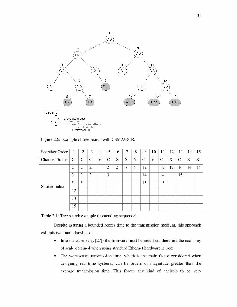
Figure 2.6 together with Table 2.1 depict the CSMA/DCR operation in a situation
where 6 messages collide. Considering that lower indexes correspond to higher priorities,
after the initial collision the right branch of the tree (messages 12, 14 and 15) cease
contending for the bus. Since there are still three messages on the left branch, a new
collision appears, between messages 2, 3 and 5. Thus, the left sub-branch is selected again,
leaving message 5 out. In the following slot, messages 2 and 3 will collide again. The sub-
branch selected after this collision has no active message sources, and thus in the following
time slot the bus will be idle (step 4). This causes a move to the right sub-branch, where
messages 3 and 5 reside, resulting in a new collision. Finally, in step 6 the branch
containing only the message with index 5 is selected, resulting in a successful
transmission. The algorithm continues this way until all messages are successfully
transmitted.
31
Figure 2.6: Example of tree search with CSMA/DCR.
Searcher Order 1 2 3 4 5 6 7 8 9 10 11 12 13 14 15
Channel Status C C C V C X X X C V C X C X X
2 2 2 2 2 3 5 12 12 12 14 14 15
3 3 3 3 14 14 15
5 5 15 15
12
14
Source Index
15
Table 2.1: Tree search example (contending sequence).
Despite assuring a bounded access time to the transmission medium, this approach
exhibits two main drawbacks:
• In some cases (e.g. [27]) the firmware must be modified, therefore the economy
of scale obtained when using standard Ethernet hardware is lost;
• The worst-case transmission time, which is the main factor considered when
designing real-time systems, can be orders of magnitude greater than the
average transmission time. This forces any kind of analysis to be very
32
pessimistic, and therefore leads to low bandwidth utilization, at least concerning
real-time traffic.
2.4.5 Virtual time CSMA
The Virtual Time CSMA protocol has been presented in [39] and [40]. It allows
implementing different scheduling policies (e.g. minimum-laxity first), and bases its
decisions on the assessment of the communication channel status, only. When the bus
becomes idle and a node has a message to transmit, it waits for a given amount of time,
related to the scheduling policy implemented. For example, if MLF (minimum laxity first)
scheduling is used, the waiting time is derived directly from the laxity using a proportional
constant. When this amount of time expires, and if the bus is still idle, the node tries to
transmit the message. If the scheduler outcome results in more than one message having
permission to be transmitted at the same time (e.g. when two messages have the same
laxity in MLF) then a collision occur. In this case the protocol can either recalculate the
waiting time using the same rule or use a probabilistic approach according to which the
messages involved in a collision are retransmitted with probability p (p-persistent). This
last option is important to sort out situations in which the scheduler cannot differentiate
messages, e.g. messages with the same laxity would always collide.
Figure 2.7 shows the operation of the Virtual-Time CSMA protocol, with MLF
scheduling.
Figure 2.7: Example of Virtual-Time CSMA operation using MLF.
As it is shown in Figure 2.7 during the transmission of message m, messages a and
b become ready and since the laxity of message a (i.e. deadline minus message
transmission time) is shorter than the laxity of message b, message a is transmitted first.

33
However during the transmission of message a, message c arrives and the messages b and c
have the same deadline and the same laxity. Therefore, an attempt will be made to transmit
them at the same time, causing a collision. Then the algorithm uses the probabilistic
approach, with message b having a lower waiting time than message c, and thus being
transmitted next. Finally, message c is transmitted on the bus. Since the only global
information is the channel status, there is no way to know that there is only a single
message pending. For this reason, after the transmission of message b the waiting time
corresponding to message c is computed, and only after the expiration of this interval
message c is finally transmitted.
Beyond the advantage of using standard Ethernet hardware, this approach also has
the advantage of not requiring any other global information but the channel status, which is
readily available at all Network Interface Cards (NICs). Thus, a fully distributed and
symmetric implementation is possible, which, in this case, also incurs in relatively low
computational overhead. Nevertheless, this approach presents some important drawbacks:
1- Performance highly dependent on the proportional constant value used to relate the
waiting time with the scheduling policy in use, leading to:
• Collisions if it is too short;
• Large amount of idle time if it is too long;
2- Proportional constant depends on the properties of the message set; therefore on-line
changes to that set can lead to poor performance;
3- The waiting times are computed locally using relative parameters, only. There is no
global time base and thus, relative phasing is hard to implement;
4- Due to possible collisions, worst-case transmission time is much higher than average
transmission time and only probabilistic timeliness guarantees can be given (soft real-
time systems).
2.5 Token passing technique
Token passing is other well-know medium access control technique suited for shared
broadcast bus or ring networks. The token is a special kind of network frame to regulate
network access of the individual nodes. The token flows from node to node and each node
may transmit a message only when it has acquired the token. In the simplest and more
common way, the token rotates in a circular fashion, which tends to divide the bandwidth

34
equally among all nodes in high traffic load conditions. For asymmetrical bandwidth
distribution some protocols allow the token to visit the same node more than once in each
token round as proposed by Cheng et al in [41]. In both cases, a basic condition for real-
time operation is that the time spent by the token at each node must be bounded. This can
be achieved by using a timed-token protocol [42] as in the well-known cases of FDDI,
IEEE 802.4 Token Bus and PROFIBUS (this one still belonging to the same class but
exhibiting a few differences).
The token passing technique is frequently used to override the native Ethernet
CSMA/CD arbitration mechanism. This subsection presents three approaches using the
token passing technique.
2.5.1 RETHER
The RETHER protocol was proposed by Venkatramani and Chiueh in [43]. This protocol
operates in normal Ethernet CSMA/CD mode until the arrival of real-time requests upon
which it switches to token-bus mode.
In token-bus mode real-time data is considered to be periodic and the time is
divided in cycles of fixed duration. During the cycle duration the access to the bus is
regulated by a token, both for real-time and non-real-time traffic. First the token visits all
nodes that are sources of RT messages. After, if there is enough time until the end of the
cycle, the token visits the sources of NRT data. An on-line admission control policy
assures that all accepted RT requests can always be served and that new RT requests
cannot jeopardize the guarantees of existing RT messages. Therefore, in each cycle all RT
nodes can send their RT messages. However, concerning the NRT traffic, no timeliness
guarantees are granted.
Figure 2.8 illustrates a possible network configuration with 6 nodes. Nodes 1 and 4
are sources of RT messages, forming the RT set. The remaining nodes have no such RT
requirements and constitute the NRT set. The token first visits all the members of the RT
set and after, if possible, the members of the NRT set.

35
Figure 2.8: Sample network configuration for RETHER.
A possible token visit sequence could be: cycle i {1 – 4 – 1 – 2 – 3 – 4 – 5 – 6}, cycle i+1
{1 – 4 – 1 – 2}, cycle i+2 {1 – 4 – 1 – 2 – 3 – 4}…. In the ith cycle the load is low enough
so that the token has time to visit the RT set plus all nodes in the NRT set, too. In the
following cycle, besides the RT set, the token only visits nodes 1 and 2 of the NRT set and,
in the next cycle, only nodes 1 through 4 of the NRT set are visited.
Due to the complete elimination of collisions, this approach supports deterministic
analysis of the worst-case network access delay, particularly for the RT traffic.
Furthermore, if the NRT traffic is known a priori, it is also possible to determine a bound
to the respective network access delay, which can be important for example, for sporadic
real-time messages. However, since the bandwidth available for NRT messages is
distributed according to the nodes order established in the token circulation list, the first
nodes always get precedence over the following ones, which end up with too long worst-
case network delays. Moreover, this method involves a considerable communication
overhead caused by the circulation of the token.
2.5.2 RT-EP: Real-Time Ethernet Protocol
The Real-Time Ethernet Protocol (RT-EP) [44] [45] is a token-passing protocol which
operates over Ethernet and which was designed to be easily analyzable using well-known
schedulability analysis techniques.

36
An RT-EP network is logically organized as a ring, each node knowing which other
nodes are its predecessor and successor. The token circulates from node to node within this
logical ring.
Access to the bus is carried in two phases, arbitration and application message
transmission. In the arbitration phase the token visits all the nodes engaged in the logical
ring. Upon token reception, each node compares the priority of its own highest priority
ready message, if any, with the priority carried in the token. If higher, the token priority is
updated. The token also carries the identity of the node that contains the highest priority
message found so far.
After one token round the arbitration phase is concluded and the token is sent
directly to the node having the highest priority ready message so that it can transmit it
(application message transmission phase). After concluding the application message
transmission, the same node starts a new arbitration phase.
RT-EP packets are carried in the Data filed of the Ethernet frames. There are two
distinct types of RT-EP packets, Token Packets and Info Packets.
The Token Packets are used during the arbitration phase, and contain: a packet
identifier, specifying the functionality of the packet; priority and station address fields,
identifying the highest priority ready message as well as the respective station ID; a set of
fields used to handle faults.
The Info Packets carry the actual application data, and contain: a packet identifier
field, specifying the packet’s type; a priority field, which contains the priority of the
message being carried; a channel ID field, identifying the receiver node; a length field,
defining the message data size; an info field, carrying the actual message data; and a packet
number field, which is a sequence number used by the fault-tolerance mechanism.
The fault-tolerance mechanism [45] allows reducing the negative impact of
message losses, particularly tokens, recovering from them within bounded time. This
mechanism is based on forcing all stations to permanently listen to the bus. Following any
transaction, the predecessor station monitors the bus waiting for the transmission of the
next frame by the receiving station. If the receiving station does not transmit any frame
within a given time window, the predecessor one assumes a message loss and retransmits
it. After a predefined number of unsuccessful retries, the receiving station is considered as
a “failing station” and it is excluded from the logical ring. This mechanism may lead to the

37
occurrence of message duplicates. The sequence number field, present both in Token and
Info packets, is used to discard the duplicate messages at the receiving nodes.
2.5.3 Other
Steffen et al [46] present an implementation of a token-passing over Ethernet. Although
aiming particularly shared Ethernet, the method may also be applied to networks like
HomePNA [47] and Power line [48].
All the nodes connected to the network have a QoS sub layer (Token-Passing
Protocol), which interfaces the Logical Link Control and the Medium Access Control
layers. The QoS sub layer overrides the native arbitration mechanism, controlling the
access to the bus via a token passing mechanism.
This protocol defines two distinct types of message streams, synchronous and
asynchronous. Synchronous traffic is assumed to be periodic, and is granted real-time
guarantees. Synchronous streams are defined by a frame transmission time, a period and a
deadline. Asynchronous traffic is handled according to a best-effort policy, and thus no
real-time guarantees are provided. Asynchronous streams are defined by frame
transmission time and a desired average bandwidth.
Whenever the token arrives at a node, the synchronous frames are sent in first
place. All nodes are granted at least a pre-defined synchronous bandwidth in all token
visits to send such type of traffic. After the synchronous bandwidth is exhausted, a node
can continue to transmit up to the exhaustion of its token holding time. After that, the token
is forwarded to the next node in the circulation list.
2.6 Virtual token passing
In essence the virtual token passing medium access control technique is a token passing.
However, rather than passing an actual data token message between masters, as is the case
in some protocol types, sufficient information is present within a normal message for each
master to assess whether it has the authority to communicate (Jenkins [49]).
This section presents the virtual token-passing bus arbitration technique according
to the implementation on the P-NET fieldbus as presented in [49], P-NET website [50] and
Tovar [51].

38
P-NET is a multi-master system that can have up to 32 masters with equal priority,
and no hierarchy needs to be managed. In P-NET all communication is based on a message
cycle principle, where a master sends a request and the addressed slave immediately
returns a response. P-NET works with the fixed data rate of 76,800 bps
The virtual token passing is implemented using two protocol counters. The first
one, the access counter (AC), holds the node address of the currently transmitting master.
When a request has been completed and the bus has been idle for τ = 40 bit periods (520µs
at 76.8Kbps), each one of the access counters is incremented by one. The master whose
access counter value equals its own unique node address is said to be holding the token,
and is allowed to access the bus. When, as the access counter is incremented, it exceeds the
“maximum number of masters”, the access counter in each master is reset to one. This
allows the first master in the cycling chain to gain access again.
The second counter, the idle bus bit period counter (IBBPC), increments for each
inactive bus bit period. Should any transactions occur, the counter is reset to zero. As
explained above, when the bus has been idle for 40 bit periods following a transfer, all the
access counters are incremented by one, and the next master is thus allowed to access the
bus.
If a master has nothing to transmit (or indeed is not even present), the bus will
continue to be inactive. Following a further period of σ = 10 bit periods (130µs), the idle
bus bit period counter will have reached 50, (60, 70…) so all the access counters will be
incremented again, allowing the next master access. The virtual token passing will
continue every 10 bit periods, until a master does require access.
The P-NET standard allows each master to perform at most one message cycle per
token visit. After receiving the token, the master must transmit a request before a certain
time has elapsed. This is denoted as the master’s reaction time, and the standard imposes a
worst-case value of up to ρ = 7 bit periods. A slave is allowed to access the bus between 11
and 30 bit periods after receiving a request, measured from the beginning of the stop bit in
the last byte of the request frame. The maximum allowed delay is then 30 bit periods
(390µs). This delay is denoted as the slave's turnaround time. To illustrate these basic
MAC procedures and the notation used, refer to Figure 2.9.

39
Figure 2.9: Concepts of message cycle, token holding time (H), slave's turnaround time, master's reaction time (ρ), idle token time (σ) and token passing time (τ) in P-NET.
Figure 2.9 shows an example of the virtual token passing principle as it is
implemented in P-NET for a system with 4 masters. According with the Figure 2.9, master
3 has the virtual token, and is receiving a response from a slave, and then the bus becomes
idle. When 40 idle bit periods have been counted, all access counters are incremented by 1,
and master 4 is allowed to access the bus. Since master 4 has not anything to send, and
after 50 bit periods, master 1 is allowed to access the bus. Master 1 does not need to use
the bus either (it may not even be present), so the virtual token is passed to master 2, when
the idle bus bit period counter reaches 60.
Since masters 2 and 3 do not require the access, the token is eventually passed on to
master 4, when the idle bus bit period counter is equal to 80. This time, master 4 does
require access. Data appears on the bus, so all idle bus bit period counters are reset to zero,
all access counters are preset to 1 and a new token cycle starts with master 1 holding the
virtual token.
All communication in P-NET is structured in a frame that consists of a series of
asynchronously transmitted 9-bit bytes (Jenkins [52]). The byte structure is shown in
Figure 2.10.
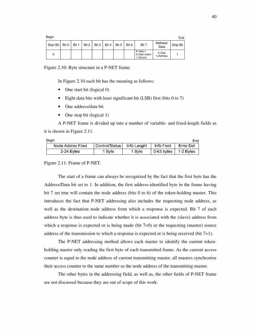
40
Start Bit Bit 0 Bit 1 Bit 2 Bit 3 Bit 4 Bit 5 Bit 6 Bit 7Address/
DataStop Bit
Begin End
0IF Add=1
0=Dest.ination
1=Source
0=Data
1=Address1
Figure 2.10: Byte structure in a P-NET frame.
In Figure 2.10 each bit has the meaning as follows:
• One start bit (logical 0)
• Eight data bits with least significant bit (LSB) first (bits 0 to 7)
• One address/data bit
• One stop bit (logical 1)
A P-NET frame is divided up into a number of variable- and fixed-length fields as
it is shown in Figure 2.11.
Figure 2.11: Frame of P-NET.
The start of a frame can always be recognized by the fact that the first byte has the
Address/Data bit set to 1. In addition, the first address-identified byte in the frame having
bit 7 set true will contain the node address (bits 0 to 6) of the token-holding master. This
introduces the fact that P-NET addressing also includes the requesting node address, as
well as the destination node address from which a response is expected. Bit 7 of each
address byte is thus used to indicate whether it is associated with the (slave) address from
which a response is expected or is being made (bit 7=0) or the requesting (master) source
address of the transmission to which a response is expected or is being received (bit 7=1).
The P-NET addressing method allows each master to identify the current token-
holding master only reading the first byte of each transmitted frame. As the current access
counter is equal to the node address of current transmitting master, all masters synchronise
their access counter to the same number as the node address of the transmitting master.
The other bytes in the addressing field, as well as, the other fields of P-NET frame
are not discussed because they are out of scope of this work.
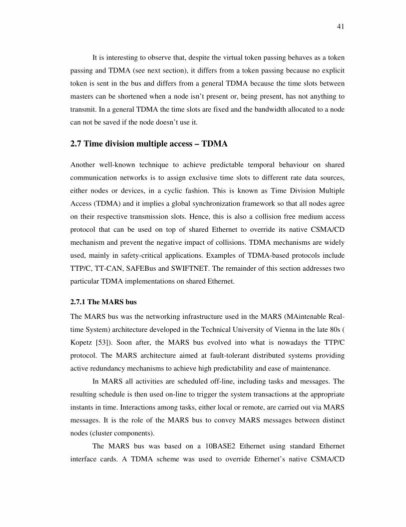
41
It is interesting to observe that, despite the virtual token passing behaves as a token
passing and TDMA (see next section), it differs from a token passing because no explicit
token is sent in the bus and differs from a general TDMA because the time slots between
masters can be shortened when a node isn’t present or, being present, has not anything to
transmit. In a general TDMA the time slots are fixed and the bandwidth allocated to a node
can not be saved if the node doesn’t use it.
2.7 Time division multiple access – TDMA
Another well-known technique to achieve predictable temporal behaviour on shared
communication networks is to assign exclusive time slots to different rate data sources,
either nodes or devices, in a cyclic fashion. This is known as Time Division Multiple
Access (TDMA) and it implies a global synchronization framework so that all nodes agree
on their respective transmission slots. Hence, this is also a collision free medium access
protocol that can be used on top of shared Ethernet to override its native CSMA/CD
mechanism and prevent the negative impact of collisions. TDMA mechanisms are widely
used, mainly in safety-critical applications. Examples of TDMA-based protocols include
TTP/C, TT-CAN, SAFEBus and SWIFTNET. The remainder of this section addresses two
particular TDMA implementations on shared Ethernet.
2.7.1 The MARS bus
The MARS bus was the networking infrastructure used in the MARS (MAintenable Real-
time System) architecture developed in the Technical University of Vienna in the late 80s (
Kopetz [53]). Soon after, the MARS bus evolved into what is nowadays the TTP/C
protocol. The MARS architecture aimed at fault-tolerant distributed systems providing
active redundancy mechanisms to achieve high predictability and ease of maintenance.
In MARS all activities are scheduled off-line, including tasks and messages. The
resulting schedule is then used on-line to trigger the system transactions at the appropriate
instants in time. Interactions among tasks, either local or remote, are carried out via MARS
messages. It is the role of the MARS bus to convey MARS messages between distinct
nodes (cluster components).
The MARS bus was based on a 10BASE2 Ethernet using standard Ethernet
interface cards. A TDMA scheme was used to override Ethernet’s native CSMA/CD

42
medium access control. The TDMA round consisted of a sequence of slots of equal
duration, each assigned to one node in a circular fashion. Moreover, during each slot the
tasks in each node were scheduled in a way to prevent contention between tasks on bus
access (Schabl [54]).
2.7.2 Variable bandwidth allocation scheme
The Variable Bandwidth Allocation Scheme has been proposed in [55] for Ethernet
networks by Lee and Shin. Basically, it is a TDMA transmission control mechanism in
which the slots assigned to each node in the TDMA round can have different durations.
This feature allows tailoring the bandwidth distribution among nodes according to their
effective communication requirements and thus it is more bandwidth efficient than other
TDMA-based mechanisms relying on equal duration slots, as it was the case in the MARS
bus. Nowadays, this feature has been incorporated in most of the existing TDMA-based
protocols, e.g. TTP/C and TT-CAN, improving their bandwidth efficiency.
Moreover, this technique also comprises the possibility of changing the system
configuration on-line, namely adding or removing nodes, a feature that is sometimes
referred to as Flexible TDMA (FTDMA) [56].
The nomenclature used in [55] uses the expression frame to refer to the TDMA
round. Both the frame duration (frame time - F) together with the slot durations (slot times
- Hi) are computed according to the specific traffic characteristics. The first slot in each
frame (Tc) is reserved for control purposes such as time synchronization and
addition/deletion of nodes. The structure of a TDMA frame is depicted in Figure 2.12.
Figure 2.12: The structure of a TDMA frame.
The transmission of the control slot, Tc, as well as the inter-slot times, represents
communication overhead. The inter-slot time must be sufficient to accommodate a residual
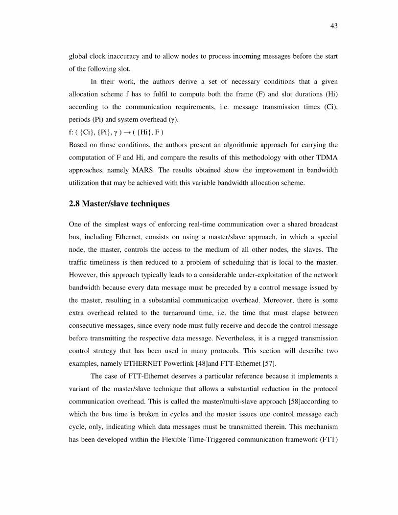
43
global clock inaccuracy and to allow nodes to process incoming messages before the start
of the following slot.
In their work, the authors derive a set of necessary conditions that a given
allocation scheme f has to fulfil to compute both the frame (F) and slot durations (Hi)
according to the communication requirements, i.e. message transmission times (Ci),
periods (Pi) and system overhead (γ).
f: ( {Ci}, {Pi}, γ ) → ( {Hi}, F )
Based on those conditions, the authors present an algorithmic approach for carrying the
computation of F and Hi, and compare the results of this methodology with other TDMA
approaches, namely MARS. The results obtained show the improvement in bandwidth
utilization that may be achieved with this variable bandwidth allocation scheme.
2.8 Master/slave techniques
One of the simplest ways of enforcing real-time communication over a shared broadcast
bus, including Ethernet, consists on using a master/slave approach, in which a special
node, the master, controls the access to the medium of all other nodes, the slaves. The
traffic timeliness is then reduced to a problem of scheduling that is local to the master.
However, this approach typically leads to a considerable under-exploitation of the network
bandwidth because every data message must be preceded by a control message issued by
the master, resulting in a substantial communication overhead. Moreover, there is some
extra overhead related to the turnaround time, i.e. the time that must elapse between
consecutive messages, since every node must fully receive and decode the control message
before transmitting the respective data message. Nevertheless, it is a rugged transmission
control strategy that has been used in many protocols. This section will describe two
examples, namely ETHERNET Powerlink [48]and FTT-Ethernet [57].
The case of FTT-Ethernet deserves a particular reference because it implements a
variant of the master/slave technique that allows a substantial reduction in the protocol
communication overhead. This is called the master/multi-slave approach [58]according to
which the bus time is broken in cycles and the master issues one control message each
cycle, only, indicating which data messages must be transmitted therein. This mechanism
has been developed within the Flexible Time-Triggered communication framework (FTT)

44
[59], and has been implemented over different network protocols, such as Controller Area
Network [60]and Ethernet [57].
2.8.1 FTT-Ethernet protocol
The FTT-Ethernet protocol [57] combines the master/multi-slave transmission control
technique with centralized scheduling, maintaining both the communication requirements
and the message scheduling policy localized in one single node, the Master, and facilitating
on-line changes to both, thus supporting a high level of operational flexibility.
The bus time is divided in fixed duration time-slots called Elementary Cycles (ECs)
that are further decomposed in two phases, the synchronous and asynchronous windows
(Figure 2.13), which have different characteristics.
Figure 2.13: FTT-Ethernet traffic structure.
The synchronous window carries the periodic time-triggered traffic that is
scheduled by the master node. The expression time-triggered implies that this traffic is
synchronized to a common time reference, which in this case is imposed by the master.
The asynchronous window carries the sporadic traffic either related to protocol control
messages, such as those conveying change requests for the time-triggered traffic, event-
triggered messages, such as those related to alarms, and other non-real-time traffic. There
is a strict temporal isolation between both phases so that the sporadic traffic does not
interfere with the time-triggered one.
Despite allowing on-line changes to the attributes of the time-triggered traffic,
global timeliness is enforced by the FTT-Ethernet protocol by means of on-line admission
control. Due to the global knowledge and centralized control of the time-triggered traffic,
the protocol supports arbitrary scheduling policies (e.g. RM and EDF), and may easily
support dynamic QoS management complementary to admission control.
45
Beyond the flexibility and timeliness properties that this protocol exhibits, there are
also some drawbacks that concern the computational overhead required in the master to
execute both the message scheduling and the schedulability analysis on-line. This is,
however, confined to one node. The computational power required by the slaves in what
concerns the communication protocol is just to decode the trigger message in time and start
the due transmissions in the right moments. Finally, in safety-critical applications the
master must be replicated, for which there are specific mechanisms to ensure coherency
between their internal databases that hold the system communication requirements.
2.8.2 ETHERNET Powerlink
ETHERNET Powerlink [77] is a commercial protocol providing deterministic isochronous
real-time communication, operating over hub-based Fast-Ethernet networks. The protocol
supports either periodic (isochronous) as well as event (asynchronous) data exchanges, a
very tight time synchronization (accuracy better than 1µs) and fast update cycles (in the
order of 500µs) for the periodic traffic. From architectural and functional points of view,
this protocol bears many resemblances with the WorldFIP fieldbus.
The ETHERNET Powerlink protocol uses a Master-Slave transmission control
technique, which completely prevents the occurrence of collisions at the bus access [61].
The network architecture is asymmetric, comprising a so-called Powerlink Manager
(Master), and a set of Powerlink Controllers (Slaves). The former device controls all the
communication activities, assigning time slots to all the remaining stations. The latter
devices, Controllers, are passive bus stations, sending information only after explicit
request from the Manager.
The Powerlink protocol operates isochronously, with the data exchanges occurring
in a cyclic framework based on a micro cycle of fixed duration, i.e. the Powerlink cycle.
Each cycle is divided in four distinct phases, called Start, Cyclic, Asynchronous and Idle
Periods (Figure 2.14).
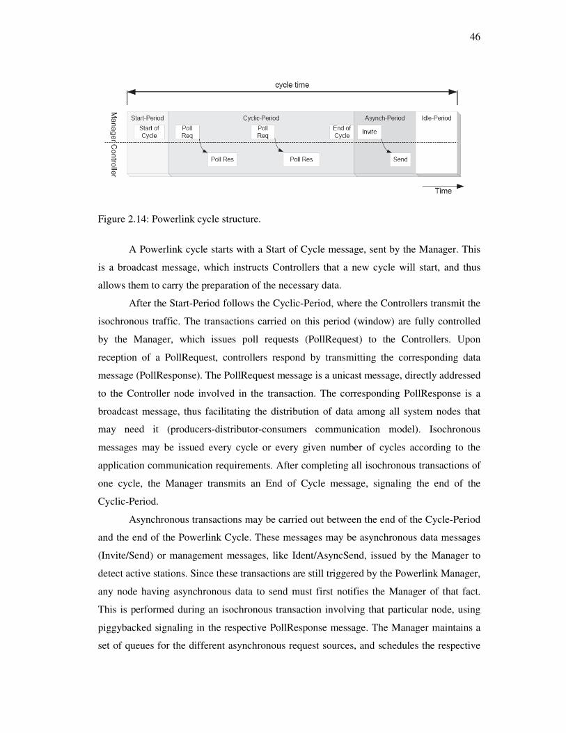
46
Figure 2.14: Powerlink cycle structure.
A Powerlink cycle starts with a Start of Cycle message, sent by the Manager. This
is a broadcast message, which instructs Controllers that a new cycle will start, and thus
allows them to carry the preparation of the necessary data.
After the Start-Period follows the Cyclic-Period, where the Controllers transmit the
isochronous traffic. The transactions carried on this period (window) are fully controlled
by the Manager, which issues poll requests (PollRequest) to the Controllers. Upon
reception of a PollRequest, controllers respond by transmitting the corresponding data
message (PollResponse). The PollRequest message is a unicast message, directly addressed
to the Controller node involved in the transaction. The corresponding PollResponse is a
broadcast message, thus facilitating the distribution of data among all system nodes that
may need it (producers-distributor-consumers communication model). Isochronous
messages may be issued every cycle or every given number of cycles according to the
application communication requirements. After completing all isochronous transactions of
one cycle, the Manager transmits an End of Cycle message, signaling the end of the
Cyclic-Period.
Asynchronous transactions may be carried out between the end of the Cycle-Period
and the end of the Powerlink Cycle. These messages may be asynchronous data messages
(Invite/Send) or management messages, like Ident/AsyncSend, issued by the Manager to
detect active stations. Since these transactions are still triggered by the Powerlink Manager,
any node having asynchronous data to send must first notifies the Manager of that fact.
This is performed during an isochronous transaction involving that particular node, using
piggybacked signaling in the respective PollResponse message. The Manager maintains a
set of queues for the different asynchronous request sources, and schedules the respective
47
transactions within the Asynch-Period, if there is time enough up to the end of the cycle. In
case there is not time enough to complete a given asynchronous transaction or there is no
scheduled asynchronous transaction then the protocol inserts idle-time in the cycle (Idle-
Period) in order to strictly respect the period of the Start of Cycle message.
ETHERNET Powerlink also handles Ethernet packets with foreign protocols, such
as TCP/IP. This traffic is conveyed within the asynchronous period. Powerlink provides a
special-purpose device driver that interfaces with such upper protocol stacks.
2.9 Switched ethernet
Since roughly one decade ago that the interest on using Ethernet switches has been
growing as a means to improve global throughput, traffic isolation and reduce the impact
of the non-deterministic features of the original CSMA/CD arbitration mechanism.
Switches, unlike hubs, provide a private collision domain for each of its ports, i.e., there is
no direct connection between its ports. When a message arrives at a switch port, it is
buffered, analyzed concerning its destination, and moved to the buffer of the destination
port (Figure 2.15). The “packet handling” block in the figure, commonly referred to as
switch fabrics, transfers messages from input to output ports. When the arrival rate of
messages at each port, either input or output, is greater than the rate of departure, the
messages are queued. Currently, most switches are fast enough handling message arrivals
so that queues do not build up at the input ports (these are commonly referred to as non-
blocking switches). However, queues may always build up at the output ports whenever
several messages arrive in a short interval and are routed to the same port. In such case,
queued messages are transmitted sequentially, normally in FCFS order. This queue
handling policy may, however, lead to substantial network-induced delays because higher-
priority or more important messages may be blocked in the queue while lower priority or
less important ones are being transmitted. Therefore, the use of several parallel queues for
different priority levels has been proposed (IEEE 802.1p). The number of distinct priority
levels is limited to 8 but many current switches that support traffic prioritization offer even
a further limited number. The scheduling policy used to handle the messages queued at
each port also impacts strongly on the network timing behavior [62].
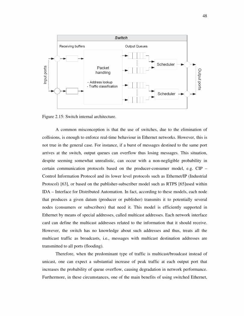
48
Figure 2.15: Switch internal architecture.
A common misconception is that the use of switches, due to the elimination of
collisions, is enough to enforce real-time behaviour in Ethernet networks. However, this is
not true in the general case. For instance, if a burst of messages destined to the same port
arrives at the switch, output queues can overflow thus losing messages. This situation,
despite seeming somewhat unrealistic, can occur with a non-negligible probability in
certain communication protocols based on the producer-consumer model, e.g. CIP –
Control Information Protocol and its lower level protocols such as Ethernet/IP (Industrial
Protocol) [63], or based on the publisher-subscriber model such as RTPS [65]used within
IDA – Interface for Distributed Automation. In fact, according to these models, each node
that produces a given datum (producer or publisher) transmits it to potentially several
nodes (consumers or subscribers) that need it. This model is efficiently supported in
Ethernet by means of special addresses, called multicast addresses. Each network interface
card can define the multicast addresses related to the information that it should receive.
However, the switch has no knowledge about such addresses and thus, treats all the
multicast traffic as broadcasts, i.e., messages with multicast destination addresses are
transmitted to all ports (flooding).
Therefore, when the predominant type of traffic is multicast/broadcast instead of
unicast, one can expect a substantial increase of peak traffic at each output port that
increases the probability of queue overflow, causing degradation in network performance.
Furthermore, in these circumstances, one of the main benefits of using switched Ethernet,

49
i.e. multiple simultaneous transmission paths, can be compromised. A possible way to limit
the impact of multicasts is using virtual LANs (VLANs) so that flooding affects only the
ports of the respective VLAN [63].
Other problems concerning the use of switched Ethernet are referred in [5]such as
the additional latency introduced by the switch in absence of collisions as well as the low
number of available priority levels that hardly supports the implementation of efficient
priority based scheduling.
According to Almeida and Pedreiras these problems are, however, essentially
technological and are expected to be attenuated in the near future. Moreover, switched
Ethernet does alleviate the non-determinism inherent to CSMA/CD medium access control
and opens to the way to efficient implementations of real-time communication over
Ethernet.
The remainder of this section presents two protocols that operate over switched
Ethernet to support real-time communication.
2.9.1 EDF scheduled switch
Hoang et al [66] [67] developed a technique that supports a mix of real-time (RT) and non-
real-time (standard IP) traffic coexisting in a switch-based Ethernet network. The RT
traffic is scheduled according to the Earliest Deadline First policy and is granted with
timeliness guarantees by means of adequate on-line admission control.
The proposed system architecture, depicted in Figure 2.16, requires the addition of
a real-time layer (RT-l) on network components, either end nodes as well as the switch.
The RT-l is responsible for establishing real-time connections, performing their admission
control, providing time synchronization, and finally managing the message transmission
and reception of both real-time and non-real-time traffic classes.

50
Figure 2.16: System architecture.
The switch RT channel management layer is responsible for providing time
synchronization through the periodic transmission of a time reference message. Moreover,
this layer also takes part in the admission control process, both by assessing the internal
state of the switch, and consequently its ability to fulfil the timeliness requirements of the
real-time message streams, as well as by acting as a broker between the nodes requesting
RT channels and the targets of such requests. Finally, this layer also disseminates the
internal switch state, namely in what concerns the queues status, to allow flow-control of
non-real-time traffic on the end nodes.
Real-time communication is carried out within real-time channels, a point-to-point
logical connection with reserved bandwidth. Whenever a node needs to send real-time
data, it issues a request to the switch, indicating both the source and destination addresses
(both MAC and IP), and the period, transmission time and deadline of the message. Upon
reception of one such request, the switch performs the first part of the admission control
mechanism, which consists in evaluating the feasibility of the communication between the
source node and the switch (uplink) and between the switch and the target node
(downlink). If the switch finds the request feasible, forwards the request to the destination
node. The target node analyses the request and informs the switch about its will on
accepting or not the real-time connection. The switch, then, forwards this answer to the
originator node. If the RT channel is accepted, it is assigned with a system wide channel ID
that univocally identifies the connection.

51
The real-time layer comprises two distinct queues, one for the real-time traffic, and
the other for the non-real-time traffic. The former is a priority queue, where messages are
kept according to the distance to their deadlines. The non-real-time queue holds the
messages in a First-In-First-Out scheme. Thus, real-time messages are transmitted
according to their deadlines, while non-real-time messages are transmitted according to
their arrival instant.
The feasibility analysis proposed by the authors is derived from EDF task scheduling
analysis, but with adaptations to account for some system specifics, such as including the
overheads due to control messages and the impact of non-preemptive message
transmission. Deadlines are defined in an end-to-end basis. Since the traffic is transmitted
in two separate steps (uplink and downlink), the analysis must assure that the total delay
induced by these steps together does not exceed the total end-to-end deadline. For a given
real-time message stream i, if diu is the deadline for the uplink and did the deadline for the
downlink, then the end-to-end deadline diee must be at least as large as the sum of the
previous two: diu + did ≤ diee. In [68] Hoang et al assume end-to-end deadlines equal to
periods, and a symmetric partitioning of the deadline between the uplink and the downlink.
An improvement is presented in [67], where the authors propose an asymmetric deadline
partition scheme. Although more complex, this method allows a higher efficiency in the
bandwidth usage, because more loaded links can receive a higher portion of the deadline,
thus increasing the overall schedulability level.
2.9.2 EtheReal
The EtheReal protocol [70] is another proposal to achieve real-time behaviour on switched
Ethernet networks. In this approach, the authors decided to leave end nodes’ operating
system and network layers untouched. The protocol is supported by services implemented
on the switch, only, and its services are accessible to the end nodes by means of user-level
libraries.
EtheReal has been designed to support both real-time and non-real-time traffic via
two distinct classes. The Real-Time Variable Bit Rate service class (RT-VBR) is meant to
support real-time applications. These services use reserved bandwidth and try to minimize
the packet delay and packet delay variation (jitter). Applications must provide the traffic
characteristics during the connection set-up, namely average traffic rate and maximum
burst length. If these parameters are violated at run-time, the real-time guarantees do not
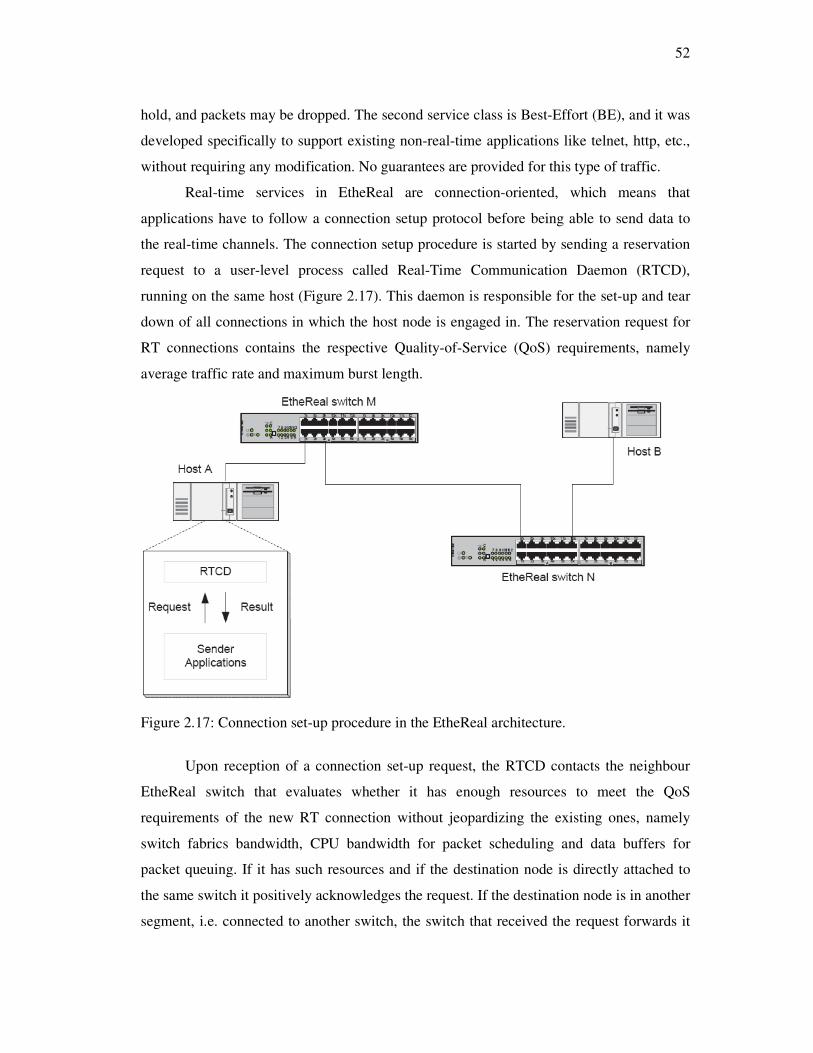
52
hold, and packets may be dropped. The second service class is Best-Effort (BE), and it was
developed specifically to support existing non-real-time applications like telnet, http, etc.,
without requiring any modification. No guarantees are provided for this type of traffic.
Real-time services in EtheReal are connection-oriented, which means that
applications have to follow a connection setup protocol before being able to send data to
the real-time channels. The connection setup procedure is started by sending a reservation
request to a user-level process called Real-Time Communication Daemon (RTCD),
running on the same host (Figure 2.17). This daemon is responsible for the set-up and tear
down of all connections in which the host node is engaged in. The reservation request for
RT connections contains the respective Quality-of-Service (QoS) requirements, namely
average traffic rate and maximum burst length.
Figure 2.17: Connection set-up procedure in the EtheReal architecture.
Upon reception of a connection set-up request, the RTCD contacts the neighbour
EtheReal switch that evaluates whether it has enough resources to meet the QoS
requirements of the new RT connection without jeopardizing the existing ones, namely
switch fabrics bandwidth, CPU bandwidth for packet scheduling and data buffers for
packet queuing. If it has such resources and if the destination node is directly attached to
the same switch it positively acknowledges the request. If the destination node is in another
segment, i.e. connected to another switch, the switch that received the request forwards it

53
to the next switch in the path. A successful connection is achieved if and only if all the
switches in the path between the source and the target node have enough resources to
accommodate the new RT connection. If some switch has not enough resources, it sends
back a reject message, which is propagated down to the requester node. This procedure
serves to notify the requester application about the result of the operation, as well as to let
the intermediate EtheReal switches to de-allocate the resources associated with that
connection request.
The EtheReal architecture employs traffic shaping and policing, both at hosts and
switches. The traffic shaping is performed to smooth the inter-packet arrival time,
generating a constant rate flow of traffic. Traffic policing is used to ensure that the
declared QoS parameters are met during runtime. Those functions are also implemented on
the switches to ensure that an ill-behaved node, either due to malfunction or malicious
software, does not harm the other connections on the network.
With respect to the packet scheduling inside the switch, the EtheReal architecture
employs a cyclic round-robin scheduling algorithm. All real-time connections are served
within a predefined cycle. A part of that cycle is also reserved to best-effort traffic, to
avoid starvation and subsequent time-outs on the upper layer protocols.
Applications access the real-time services by means of a Real-Time Data
Transmission/Reception library (RTTR), which, besides other internal functions, like the
traffic shaping and policing, provides services to connection set-up and tear down and data
transmission and reception.
Another interesting feature of this protocol is its scalability and high recovery
capability, when compared with standard switches. For example, the spanning tree protocol
(IEEE 802.3D) is used in networks of standard switches to allow redundant paths and
automatic reconfiguration upon a link/switch failure. However, such reconfiguration may
take up to 30s with the network down, which is intolerable for most real-time applications.
On the other hand, the authors claim that EtheReal networks may recover nearly 1000
times faster, within 32 ms [71].
2.10 Recent advances
Most of the recent work performed on real-time Ethernet targets switch-based
implementations. However, as discussed before, just replacing a hub by a switch is not
54
enough to make an Ethernet network exhibit real-time behaviour. One of the issues
recently addressed in the literature concerns the way packets are handled by the protocol
software (protocol stack) within the system nodes. Most of the operating systems
implement a single queue, usually working according to a First-Come First-Served policy,
for both real and non-real-time traffic. This approach induces important delays and priority
inversions. A methodology that has been proposed to solve this problem is the
implementations of multiple transmit/receive queues [72]. With this approach, the real-
time traffic is intrinsically separated from the non-real-time traffic. Non-real-time traffic is
only sent/processed when the real-time queues are empty. It is also possible to build
separate queues for each traffic class, providing internal priority-aware scheduling.
Other important issue concerns the degree of freedom in the network topology (e.g.
bus, star). The topology impacts on the number of switches that messages have to cross
before reaching the target, which impacts on the temporal properties of the traffic [73][74].
For instance, the bus (or line) topology, in which each device integrates a simplified switch
eases the cabling, but is the most unfavourable topology for real-time behaviour.
Another aspect concerning switch-based Ethernet networks respects the scheduling
policy within the switch itself. Switches support up to eight distinct statically prioritized
traffic classes. Different message scheduling strategies have a strong impact on the real-
time behaviour of the switch [75]. Particularly, strategies oriented towards average
performance and fairness, which is relevant for general-purpose networks, may impact
negatively on the switch real-time performance.
Finally, the interest on shared Ethernet is not over, yet, either for applications
requiring frequent multicasting, in which case the benefits of using switches are
substantially reduced, as well as for applications requiring precise control of transmission
timing, such as high speed visual servoing. In fact, switches induce higher delay and jitter
in message forwarding than hubs, caused by internal mechanisms such as MAC address to
port translation in forwarding and spanning-tree management protocol. In the previous
sections, several examples of this interest were discussed, such as the recent work on
adaptive traffic smoothing [76]and master/slave techniques including both the
ETHERNET Powerlink [77]as well as FTT-Ethernet [57]protocols. This last protocol is
also being analyzed for implementation on switched Ethernet, taking advantage of the
message queuing in the switch ports and thus simplifying the transmission control. This

55
has the potential to ease the implementation of slave nodes since then it would not be
necessary to enforce fine control of the transmission instants of both synchronous and
asynchronous messages, strongly reducing the computational overhead. Several existing
Ethernet-based industrial protocols, such as Ethernet/IP, are also taking advantage of
switches to improve their real-time capabilities [78][79]. Particularly this protocol is now
receiving unprecedented support from major international associations of industrial
automation suppliers, such as Open DeviceNet Vendor Association (ODVA), ControlNet
International (CNI), Industrial Ethernet Association (IEA) and Industrial Automation Open
Networking Alliance (IAONA).
2.11 Conclusion
Due to several reasons, Ethernet became the most popular technology for LANs, today.
This makes it very attractive even in application domains for which it was not originally
designed, in order to benefit from its low cost, high availability and easy integration with
other networks, just to name a few arguments. Some of such application domains, e.g.
industrial automation, impose real-time constraints on the communication services that
must be delivered to the applications. These conflicts with the original medium access
control technique embedded in the protocol, CSMA/CD, which is non-deterministic and
behaves very poorly with medium to high network loads. Therefore, along its near 30 years
of existence, many adaptations and technologies for Ethernet have been proposed in order
to support the desired real-time behaviour.
This chapter has presented some real-time Ethernet approaches, ranging from
changes to the bus arbitration, to the addition of transmission control layers and also, to the
use of special networking equipment, such as switches. Such techniques have been
described and analyzed in what concerned their pros and cons for different types of
application. By last is presented a reference to recent trends where the growing impact of
switches is clear. However, shared Ethernet might still be preferable, such as when the
traffic is mainly of a multicast nature or a precise transmission timing control is required.
With the current high pressure to bring Ethernet more and more into the world of
distributed automation systems, it is likely that such technology will end up taking the
place of existing fieldbuses and establishing itself as the de facto communication standard
for this area. Although its efficiency in terms of bandwidth utilization is still low when

56
considering short messages, particularly lower than with several fieldbuses, its high and
still growing bandwidth seems more than enough to supplant such aspect. Ethernet will
then become the long awaited single networking technology within automation systems,
which will support the integration of all levels, from the plant floor to the management,
maintenance and supply-chain.

57
Chapter 3
Virtual Token Passing Ethernet –VTPE
3.1 Introduction
Chapter 2 presented and discussed the most relevant approaches to achieve real-time
communication over Ethernet. It is interesting to remember that such approaches have
some drawbacks such as specialized hardware is required, or it is a single node solution as
the hBEB protocol, or they are not well suited to be implemented in devices with small
processing power due to the overhead imposed and the memory requirements, or finally
they are not able to separate the standard Ethernet traffic from the real-time traffic. We
believe that shared Ethernet is yet a promising solution to interconnect devices at the field
level due to the numerous advantages discussed in the previous chapters. We advocate then
that there is a need to find a real-time shared Ethernet solution adequate to be installed in
sensors, controllers and actuators used in distributed embedded systems. We also believe
that the VTPE protocol can be one of those solutions.
So, in order to develop the VTPE protocol, the following goals have been defined:
• Support, on the same bus, of slow and low cost devices based in
microcontrollers, as well as more demanding devices integrating powerful
processors;
• Low processing overhead in order to be implemented in microcontrollers
with low processing power;
• Implementation based on COTS components;
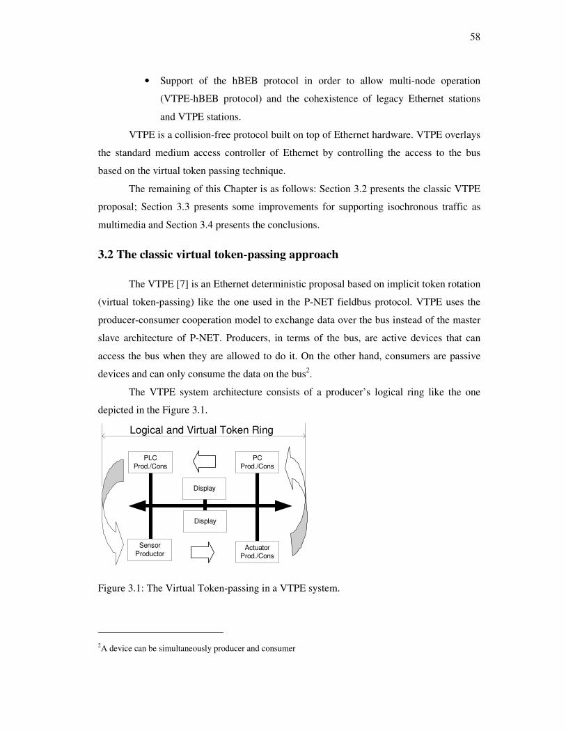
58
• Support of the hBEB protocol in order to allow multi-node operation
(VTPE-hBEB protocol) and the cohexistence of legacy Ethernet stations
and VTPE stations.
VTPE is a collision-free protocol built on top of Ethernet hardware. VTPE overlays
the standard medium access controller of Ethernet by controlling the access to the bus
based on the virtual token passing technique.
The remaining of this Chapter is as follows: Section 3.2 presents the classic VTPE
proposal; Section 3.3 presents some improvements for supporting isochronous traffic as
multimedia and Section 3.4 presents the conclusions.
3.2 The classic virtual token-passing approach
The VTPE [7] is an Ethernet deterministic proposal based on implicit token rotation
(virtual token-passing) like the one used in the P-NET fieldbus protocol. VTPE uses the
producer-consumer cooperation model to exchange data over the bus instead of the master
slave architecture of P-NET. Producers, in terms of the bus, are active devices that can
access the bus when they are allowed to do it. On the other hand, consumers are passive
devices and can only consume the data on the bus2.
The VTPE system architecture consists of a producer’s logical ring like the one
depicted in the Figure 3.1.
PLC
Prod./Cons
PC
Prod./Cons
Display
Display
Sensor
ProductorActuator
Prod./Cons
Logical and Virtual Token Ring
Figure 3.1: The Virtual Token-passing in a VTPE system.
2A device can be simultaneously producer and consumer

59
In the example of Figure 3.1, the distributed system is composed of six nodes, one
producer (sensor), three producer/consumers (actuator, PC and PLC) and two consumers
(Displays). The hardware of each node consists of a processor or microcontroller attached
to an Ethernet controller.
This proposal of VTPE uses broadcast destination addressing. The reasons for
broadcast addressing are to simplify the hardware, to reduce costs, and to allow the VTPE
to be implemented in a wide range of available Ethernet controllers. When using broadcast
addressing an interrupt is generated whenever a frame is transmitted in the bus and the
interrupts are used to do the system synchronisation.
In a VTPE system each producer node has a node address (NA), between 1 and the
number of producers expected within a system. All producers have an Access Counter
(AC), which identifies the node that can access the bus in a specific time interval.
Whenever a frame is sent to the bus, an interrupt must be generated in all producer nodes.
After the interrupt all nodes increase their ACs and the producer node whose AC value is
equal to its own unique address, is allowed to access the bus. If the actual node doesn’t
have anything to transmit (or indeed is not present), the bus becomes idle and, after a
certain time, all the access counters are increased by one. The next producer is then
allowed to access the bus. If, again, it has nothing to transmit, the bus continues idle and
the described procedure is repeated until a producer effectively uses the bus.
The procedure described in the previous paragraph accelerates token rotation time
when producers have nothing to transmit. However, if it is used just like described, it can
lead to a long idle time in the bus. The absence of bus activity can result in clock drift,
which, in turn, could lead to AC inconsistencies among system nodes. To prevent this
situation the VTPE forces the periodic transmission of a frame with k period to
synchronize all access counters. To do this all producers must have an Idle Bus Counter
IBC, which indicates how many times the bus became idle and no message was sent. All
producers also have a timer, which can be programmed with time value t1 or t2. t1 must be
long enough to enable the slowest processor in the system to decode the VTPE frame (read
the frame). t2 is used to guarantee the token passing when one or more producers don’t
have something to transmit. t1 and t2 will be discussed further as well as the k value.
To explain the VTPE operation lets see the flow chart depicted in Figure 3.2.
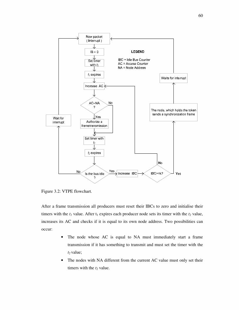
60
Figure 3.2: VTPE flowchart.
After a frame transmission all producers must reset their IBCs to zero and initialise their
timers with the t1 value. After t1 expires each producer node sets its timer with the t2 value,
increases its AC and checks if it is equal to its own node address. Two possibilities can
occur:
• The node whose AC is equal to NA must immediately start a frame
transmission if it has something to transmit and must set the timer with the
t2 value;
• The nodes with NA different from the current AC value must only set their
timers with the t2 value.
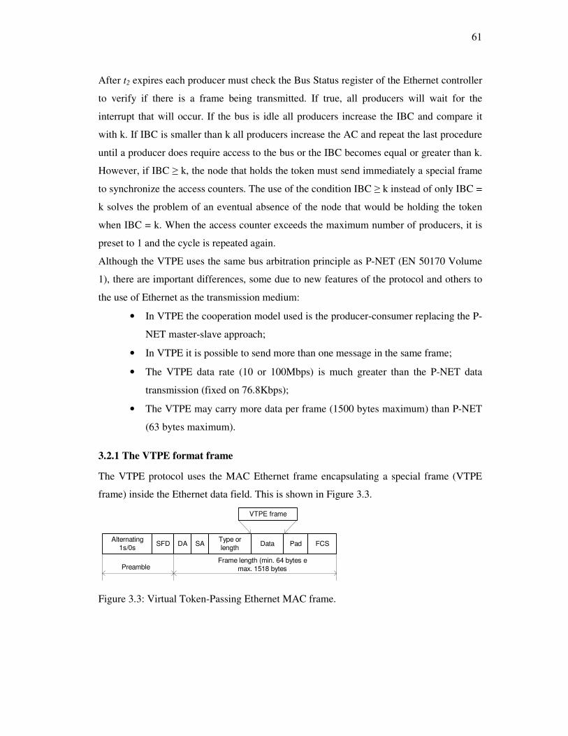
61
After t2 expires each producer must check the Bus Status register of the Ethernet controller
to verify if there is a frame being transmitted. If true, all producers will wait for the
interrupt that will occur. If the bus is idle all producers increase the IBC and compare it
with k. If IBC is smaller than k all producers increase the AC and repeat the last procedure
until a producer does require access to the bus or the IBC becomes equal or greater than k.
However, if IBC ≥ k, the node that holds the token must send immediately a special frame
to synchronize the access counters. The use of the condition IBC ≥ k instead of only IBC =
k solves the problem of an eventual absence of the node that would be holding the token
when IBC = k. When the access counter exceeds the maximum number of producers, it is
preset to 1 and the cycle is repeated again.
Although the VTPE uses the same bus arbitration principle as P-NET (EN 50170 Volume
1), there are important differences, some due to new features of the protocol and others to
the use of Ethernet as the transmission medium:
• In VTPE the cooperation model used is the producer-consumer replacing the P-
NET master-slave approach;
• In VTPE it is possible to send more than one message in the same frame;
• The VTPE data rate (10 or 100Mbps) is much greater than the P-NET data
transmission (fixed on 76.8Kbps);
• The VTPE may carry more data per frame (1500 bytes maximum) than P-NET
(63 bytes maximum).
3.2.1 The VTPE format frame
The VTPE protocol uses the MAC Ethernet frame encapsulating a special frame (VTPE
frame) inside the Ethernet data field. This is shown in Figure 3.3.
Alternating
1s/0sSFD DA SA
Type or
lengthData Pad FCS
VTPE frame
PreambleFrame length (min. 64 bytes e
max. 1518 bytes
Figure 3.3: Virtual Token-Passing Ethernet MAC frame.

62
The VTPE uses the type field instead of the length. It represents a reserved constant
value, which must be used by all the VTPE messages on the network. The use of this field
allows supporting the coexistence, in the same network, of other protocols. On frame
reception, the nodes check the type field and only perform further processing if the frame
is relevant. Nevertheless, the nodes producing non-VTPE frames must implement the
VTPE access control, and transmit frames only if its AC is equal to its NA.
The VTPE frame carries one control field and one or more messages as it is
depicted in the Figure 3.4.
NI,GI R Identifier Length TTD Data
Control field Message field
Figure 3.4: VTPE frame format.
Since VTPE can send more than one message inside a single Ethernet frame more
efficient bandwidth utilization is achieved due to the reduction on padding in case of small
messages. Like it is shown in Figure 3.4, the VTPE frame is composed of two parts: the
control field and the messages field.
Control field
The control field is two bytes long and the first byte is divided in two parts. The four less
significant bits (NI) identify the number of messages inside the Ethernet frame (up to 16
messages). However this number can be reduced to bind the amount of information that
each node must handle on frame reception, favouring the use of small processing power
devices. The remaining four bits are the Group Identifier (GI), which will be used to create
different producer groups, i.e, sub-networks. The GI idea permits to reduce processing
overhead in the nodes by isolating devices that do not belong to the same group. In fact, on
frame reception, the nodes check the GI field and only perform further processing if the
frame is relevant. Nevertheless, the node must implement the VTPE medium access
control. The second byte of the control field (R) is reserved for future use.
Message field
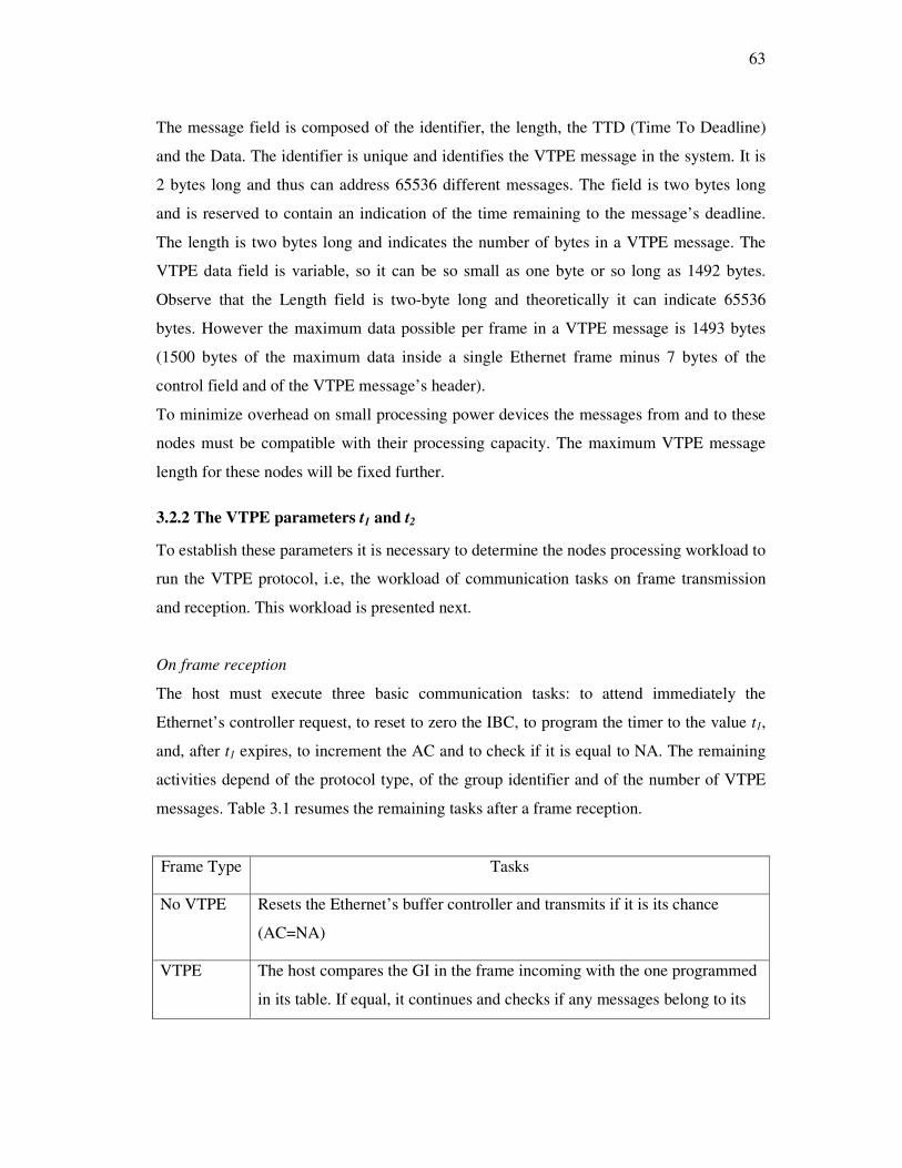
63
The message field is composed of the identifier, the length, the TTD (Time To Deadline)
and the Data. The identifier is unique and identifies the VTPE message in the system. It is
2 bytes long and thus can address 65536 different messages. The field is two bytes long
and is reserved to contain an indication of the time remaining to the message’s deadline.
The length is two bytes long and indicates the number of bytes in a VTPE message. The
VTPE data field is variable, so it can be so small as one byte or so long as 1492 bytes.
Observe that the Length field is two-byte long and theoretically it can indicate 65536
bytes. However the maximum data possible per frame in a VTPE message is 1493 bytes
(1500 bytes of the maximum data inside a single Ethernet frame minus 7 bytes of the
control field and of the VTPE message’s header).
To minimize overhead on small processing power devices the messages from and to these
nodes must be compatible with their processing capacity. The maximum VTPE message
length for these nodes will be fixed further.
3.2.2 The VTPE parameters t1 and t2
To establish these parameters it is necessary to determine the nodes processing workload to
run the VTPE protocol, i.e, the workload of communication tasks on frame transmission
and reception. This workload is presented next.
On frame reception
The host must execute three basic communication tasks: to attend immediately the
Ethernet’s controller request, to reset to zero the IBC, to program the timer to the value t1,
and, after t1 expires, to increment the AC and to check if it is equal to NA. The remaining
activities depend of the protocol type, of the group identifier and of the number of VTPE
messages. Table 3.1 resumes the remaining tasks after a frame reception.
Frame Type Tasks
No VTPE Resets the Ethernet’s buffer controller and transmits if it is its chance
(AC=NA)
VTPE The host compares the GI in the frame incoming with the one programmed
in its table. If equal, it continues and checks if any messages belong to its
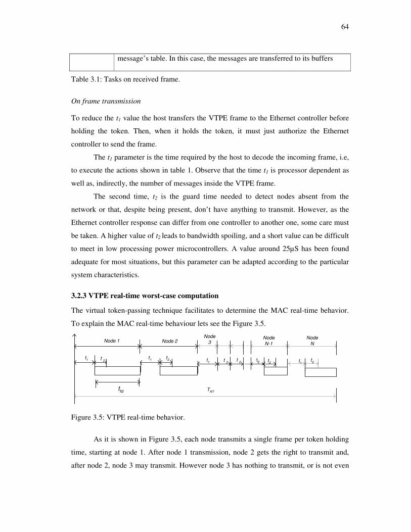
64
message’s table. In this case, the messages are transferred to its buffers
Table 3.1: Tasks on received frame.
On frame transmission
To reduce the t1 value the host transfers the VTPE frame to the Ethernet controller before
holding the token. Then, when it holds the token, it must just authorize the Ethernet
controller to send the frame.
The t1 parameter is the time required by the host to decode the incoming frame, i.e,
to execute the actions shown in table 1. Observe that the time t1 is processor dependent as
well as, indirectly, the number of messages inside the VTPE frame.
The second time, t2 is the guard time needed to detect nodes absent from the
network or that, despite being present, don’t have anything to transmit. However, as the
Ethernet controller response can differ from one controller to another one, some care must
be taken. A higher value of t2 leads to bandwidth spoiling, and a short value can be difficult
to meet in low processing power microcontrollers. A value around 25µS has been found
adequate for most situations, but this parameter can be adapted according to the particular
system characteristics.
3.2.3 VTPE real-time worst-case computation
The virtual token-passing technique facilitates to determine the MAC real-time behavior.
To explain the MAC real-time behaviour lets see the Figure 3.5.
t1 t
2t2
t1
Node 1 Node 2
t1
t2
t2
t2
tfd T
RT
Node
N-1
t1
Node
N
t2
Node
3
t2
Figure 3.5: VTPE real-time behavior.
As it is shown in Figure 3.5, each node transmits a single frame per token holding
time, starting at node 1. After node 1 transmission, node 2 gets the right to transmit and,
after node 2, node 3 may transmit. However node 3 has nothing to transmit, or is not even

65
connected to the bus, thus no transmission occurs and then only t1 appears in the timeline.
After node 3 some other nodes are not present or have nothing to transmit and the bus
remains silent until a node in the chain gets the right to transmit and transmits. When node
N, the last node, transmits a frame the AC is preset to 1 and the node 1 gets the right of
transmission again. The TRT(n) is the time between the nth and (n+1)th token visits of a
specific node, i.e., the time between two consecutive transmissions. Its value can be found
based on the scenario depicted in the Figure 3.5.
Thus from Eq 3.1 it is possible to calculate the TRT(n) where N is the number of
nodes, t1 is as mentioned before, and tfd(k,n) is the duration of the frame transmitted by
node k in the nth token visit. The term f(k,n) is a flag which is equal to 1 if node k
transmits during the nth token visit and is 0 otherwise.
[ ]∑=
−++=N
k
fdRT nkftnkfnkttnT1
21 )),(1(*),(*)),(()( (3.1)
The maximum Token Rotation Time TRTmax can be calculated by equation Eq 3.2
where tfd max(k) is the time to transmit the largest VTPE frame from node k. It is assumed
that all nodes transmit during this worst case round.
∑=
+=N
k
fdRT kttNT1
max1max )(* (3.2)
The equation (3.1) and equation (3.2) show that the VTPE MAC behaviour is
deterministic, besides being very simple to determine the TRT.
VTPE, as well as P-NET, were designed to ensure that any particular master has no
hierarchical priority over any other. In VTPE the virtual token rotates in a circular list
according to the increasing addresses of masters and each master can access the bus once
per each token rotation cycle. VTPE, as well as P-NET, due to the nature of token-passing
in a circular list, has the potential to create large blocking periods between consecutive
token arrivals. In VTPE the blocking is strongly dependent of the quantity of nodes and of
the length of each transmitted message during a token rotation. The blocking B, in the
worst case, can be calculated by the equation (3.3). As it shown in equation (3.3) each
node is blocked by (N-1) times per each rotation time.
∑−
=
+−=1
1max1 )(*)1(
N
kfd
ktNB t (3.3)

66
A solution to avoid or, at least, to limit this blocking will be discussed further in this
document.
3.2.4 Some experimental results
An implementation of VTPE over an Ethernet 10Mbps hub was reported in [80]. An
enlarged description of the experimental setup can be found in the Chapter 6. In this
implementation the nodes are based on a PIC microcontroller 18F458 with full processing
capacity allocated to run VTPE. Some results of this implementation are summarised in
Table 3.2.
Table 3.2 shows the t1 values according to the maximum length of the transmitted
frames and the network utilisation achieved for the implementation presented in the
Section 3.2. The modest network throughput is due to the low processing power of the
microcontrollers and to the overhead imposed to the nodes in order to accept all
transmitted frames and to do some processing on each frame. In fact, using current
standard Ethernet controllers, it becomes heavy to implement the VTPE, because it is
impossible to read a frame during its transmission and to execute the VTPE procedure
simultaneously. This can be minimised with adapted controllers, e.g., using dual controller
architectures, or can be solved using FPGAs and IP cores [81].
Data
(Bytes)
Frame Length including preamble
(Bytes) and Start Frame Delimiter
tfdmax (µS) t1 (µS) Network Utilisation
U=(1-t1/(t1+tfd))
46 72 57.6 297.60 16.2
138 164 131.2 693.60 15.9
276 302 241.6 1288.8 15.8
414 440 352.0 1883.2 15.8
552 578 462.4 2476.8 15.7
690 716 572.8 3071.2 15.7
828 854 683.2 3665.6 15.7
966 992 793.6 4260.0 15.7
1104 1130 904.0 4854.4 15.7
1242 1268 1014.4 5448.0 15.7
Table 3.2: VTPE experimental results.
67
Using the values from the implementation referred above, we can highlight the
problem associated to the blocking caused by the circular token rotation. For example,
consider a system comprised of 5 nodes with the frame parameters shown in the bold line
of Table 3.2. The maximum token rotation time, TRTmax, calculated by equation (3.2) is
14.696ms. This means that a node can only transmit about 68 frames per second, which is
clearly insufficient for bandwidth and timeliness demanding streams such as those of
multimedia applications.
Therefore, the classic version of VTPE is not well suited to support multimedia traffic that
is becoming more frequent in control and monitoring applications. The two main
disadvantages are:
• The token rotation time depends on the processing power of the processors
used because t1 must be long enough to enable the decoding of the
maximum frame broadcasted;
• By protocol definition there is no priority among the nodes;
The first disadvantage can be solved if nodes are restricted to be implemented with
high processing power processors and 100Mbps Ethernet controllers. However, to
overcome the last restriction, enhancements in the VTPE protocol must be made.
3.3. Adapting VTPE to support isochronous traffic
Besides the usual control loops where sensors, controllers and actuators must exchange
information, the use of more resource demanding applications, such as multimedia for
control and monitoring has increased significantly in modern Digital Computer Control
Systems (DCCS). This means that the communication link among the different system
elements must allow the coexistence of multimedia traffic and control traffic. These
communications needs have been already pointed out by Javier Blanes [82], Stankovic
[83], Pimentel [84], Dietrich [85], and Neumann [86], among others.
At the field level, a network capable to perform the integration of multimedia and
control traffic must be able to handle large frames in a bounded time, besides supporting
the generic requirements of DCCSs pointed out by Pimentel [84] and Decotignie [5], such
as the indication of temporal consistency, point-to-point and multicast communication,
robustness in terms of interference and vibration, etc. Then the network protocol must
allocate the network bandwidth so that the nodes that are source of multimedia traffic or

68
any other control traffic with stringent timing constraints have guaranteed access to the
medium in the time specified by the application. To alleviate the blocking problem caused
by the circular list, two main approaches have been followed: using a sufficiently small
target token rotation time, with appropriate design of synchronous bandwidths [87] and
creating non-circular lists where a given node can be visited several times in a full token
rotation [41].
In order to alleviate the blockings caused by the circular token rotation, we decided
to follow an approach similar to the one proposed in [41], which consists in using a non-
circular token rotation so that the token may visit the same node more than once in each
rotation. In order to support this feature an extension of VTPE is proposed which
implements a bandwidth allocation scheme that gives higher priority to the nodes that are
source of isochronous traffic or, at least, gives them the right to access the network more
often than regular nodes. This more frequent access can be accomplished with an almost
regular period, which may be different from node to node and which seems adequate for
isochronous traffic.
3.3.1 The bandwidth allocation scheme
The bandwidth allocation scheme proposed is a simple mechanism that can be readily
added to both VTPE and P-NET protocols. This scheme also uses an access counter which
value must be similar in all nodes and which must also be incremented simultaneously in
each node, either after a time out or after the end of transmission of a frame. Instead of
comparing the access counter AC value with the node address, as in the referred protocols,
masters will use this value to check the status of a flag located in the correspondent
position within a table. This table has been named Bandwidth Allocation Table (BAT) and
it consists of an array of flags with a dimension M (Table 3.3). If a master finds a flag ON
in the position corresponding to its current AC counter value then it is allowed to access
the network. The AC value is then now a pointer to a position in the BAT table when the
correspondent flag indicates if there is or not the right to transmit. This means that all other
masters must have their flags OFF in the same position. In order to reuse the software from
the virtual token passing scheme, the ON flags can be integer numbers from 1 to M. It
means that, in a real implementation, the BAT table in every node contains not a “0” or “1”
value, i.e. a flag, but a 0 or n figure n being the current BAT position. For instance, BAT1
in the exempla of Table 3.3 that follows would be 1,0,3,0 instead of 1,0,1,0. From now on
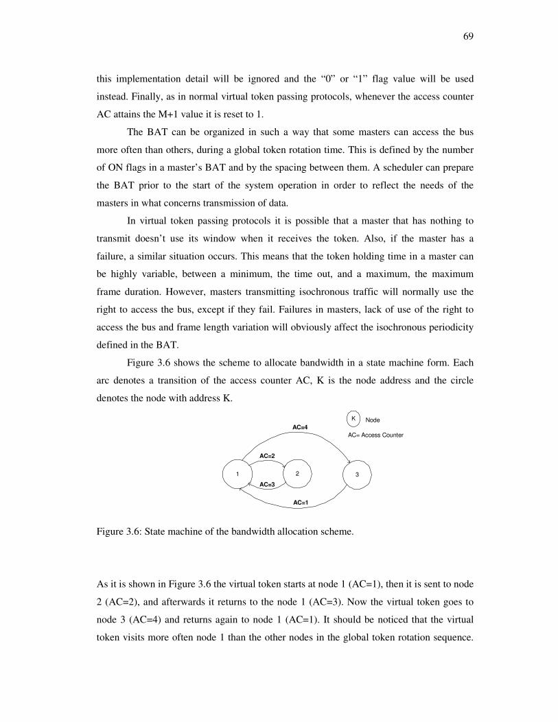
69
this implementation detail will be ignored and the “0” or “1” flag value will be used
instead. Finally, as in normal virtual token passing protocols, whenever the access counter
AC attains the M+1 value it is reset to 1.
The BAT can be organized in such a way that some masters can access the bus
more often than others, during a global token rotation time. This is defined by the number
of ON flags in a master’s BAT and by the spacing between them. A scheduler can prepare
the BAT prior to the start of the system operation in order to reflect the needs of the
masters in what concerns transmission of data.
In virtual token passing protocols it is possible that a master that has nothing to
transmit doesn’t use its window when it receives the token. Also, if the master has a
failure, a similar situation occurs. This means that the token holding time in a master can
be highly variable, between a minimum, the time out, and a maximum, the maximum
frame duration. However, masters transmitting isochronous traffic will normally use the
right to access the bus, except if they fail. Failures in masters, lack of use of the right to
access the bus and frame length variation will obviously affect the isochronous periodicity
defined in the BAT.
Figure 3.6 shows the scheme to allocate bandwidth in a state machine form. Each
arc denotes a transition of the access counter AC, K is the node address and the circle
denotes the node with address K.
1 2 3
AC=2
AC=4
AC=1
AC=3
K Node
AC= Access Counter
Figure 3.6: State machine of the bandwidth allocation scheme.
As it is shown in Figure 3.6 the virtual token starts at node 1 (AC=1), then it is sent to node
2 (AC=2), and afterwards it returns to the node 1 (AC=3). Now the virtual token goes to
node 3 (AC=4) and returns again to node 1 (AC=1). It should be noticed that the virtual
token visits more often node 1 than the other nodes in the global token rotation sequence.
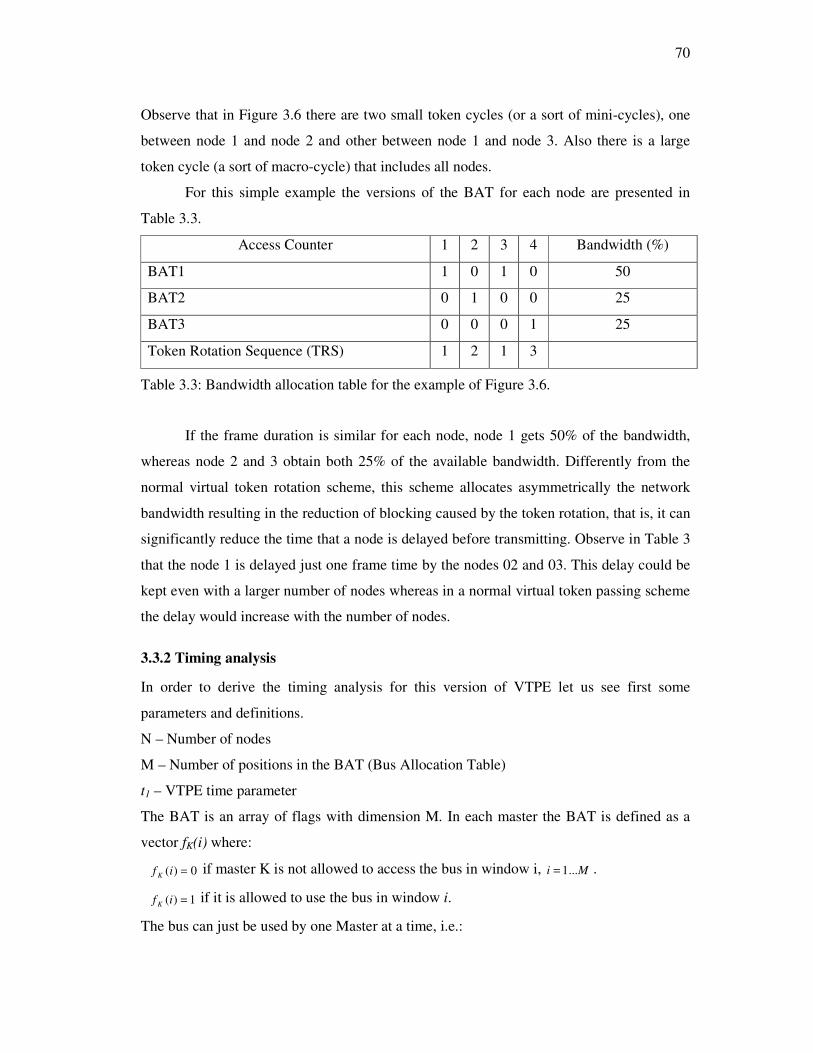
70
Observe that in Figure 3.6 there are two small token cycles (or a sort of mini-cycles), one
between node 1 and node 2 and other between node 1 and node 3. Also there is a large
token cycle (a sort of macro-cycle) that includes all nodes.
For this simple example the versions of the BAT for each node are presented in
Table 3.3.
Access Counter 1 2 3 4 Bandwidth (%)
BAT1 1 0 1 0 50
BAT2 0 1 0 0 25
BAT3 0 0 0 1 25
Token Rotation Sequence (TRS) 1 2 1 3
Table 3.3: Bandwidth allocation table for the example of Figure 3.6.
If the frame duration is similar for each node, node 1 gets 50% of the bandwidth,
whereas node 2 and 3 obtain both 25% of the available bandwidth. Differently from the
normal virtual token rotation scheme, this scheme allocates asymmetrically the network
bandwidth resulting in the reduction of blocking caused by the token rotation, that is, it can
significantly reduce the time that a node is delayed before transmitting. Observe in Table 3
that the node 1 is delayed just one frame time by the nodes 02 and 03. This delay could be
kept even with a larger number of nodes whereas in a normal virtual token passing scheme
the delay would increase with the number of nodes.
3.3.2 Timing analysis
In order to derive the timing analysis for this version of VTPE let us see first some
parameters and definitions.
N – Number of nodes
M – Number of positions in the BAT (Bus Allocation Table)
t1 – VTPE time parameter
The BAT is an array of flags with dimension M. In each master the BAT is defined as a
vector fK(i) where:
0)( =if K if master K is not allowed to access the bus in window i, Mi ...1= .
1)( =if K if it is allowed to use the bus in window i.
The bus can just be used by one Master at a time, i.e.:
71
[ ] [ ]NKjMiifif jK ,1,,1,0)(1)( ∈≠∀∈∀=⇒= (3.4)
So, the overall bus allocation can be represented by the array of binary flags indicated in
eq.3.5. In each position the flag will be 1 when there is a master that has the right to
transmit with AC=i and 0 otherwise:
MiififN
j
j ...1,)()(1
0 ==∑=
(3.5)
The token rotation time is not anymore identical for all masters. If a master K is just
allowed to access the bus once per full count of the Access Counter AC, then the token
rotation cycle has a duration given by equation (3.6).
( )[ ]∑=
+−−++−=M
i
fdRTmc ttififittifift1
2100100 )*)1((*))(1()(*)1(*)( (3.6)
In equation (3.6) the tfd(i) are the durations of the frames transmitted by the nodes with
AC=i, if they have something to transmit. These are considered identical in every token
cycle n, and then this index is dropped in tfd. If the tfd values are unknown then tfdmax, the
maximum frame duration, can be used. Also notice that f0(0) = f0(M) by definition.
The tRTmc figure measures the time it takes to repeat the token visit sequence
pattern. It is independent of the specific master considered. It is similar to what is called a
macro-cycle in communication schedules. Because of that a mc subscript is added.
If the bus is fully used, then every element of the array of eq. 3.5 will be 1. The
maximum rotation time of a master that transmits only once during this sort of macro cycle
(i.e. the maximum macro cycle duration), happens when all masters transmit a frame with
maximum duration and when the macro-cycle is fully used. Equation (3.7) can then be
applied:
)(* max1max fdRTmc ttMt += (3.7)
Masters with isochronous traffic will be authorized to access the bus more than
once per macro-cycle. The number of accesses per macro-cycle is given by:
∑=
=M
i
KK ifNacc1
)( (3.8)

72
A maximum bound for the average value of the token rotation time for these
masters can be obtained using the worst case macro-cycle duration:
K
RTmcKRTavg
Nacc
tt max
, = (3.9)
An average value can be obtained using a tRTmcavg that results from replacing in
equation (3.7) tfdmax with tfdavg, which is the average frame duration.
In normal situations different periodicity requirements of isochronous traffic of the
masters will result in mutual interference between traffic flows. A bus schedule without
period jitter will be practically impossible to obtain as it is typical in token-based system.
In order to analyze the period variations for a master, it is required to determine the
minimum and maximum time between consecutive token visits for that specific master.
One possibility is to determine the number of the BAT positions between consecutive flags
ON for that master. This leads to NaccK number of LK(i) values as given by equation
(3.10).
[ ]KMMODK NacciabiL ,1)()( ∈∀−=
where
(3.10)
( ) bjajfbfaf KKK <<=∧== ,0)(1)( (3.11)
Using modulus M arithmetic it is easy to obtain the value for the interval between
the last access in the current macro-cycle and the first in the next one.
The minimum and maximum values for the token rotation time of master K can
then be obtained either using a pessimistic view that ignores the schedule of the bus
between two successive accesses of the master or using a more accurate estimate resulting
from the analysis of the effective bus usage between the a and b points of the LK(i)
calculation.
For the first case, considering that t2 < t1 + tfd min, i.e., that the time out to detect the
bus idle when a node has nothing to transmit is always smaller than the minimum
occupation of the bus when the nodes are transmitting, the minimum token rotation time is:
)1))(((min(* ...121minmin, −++= = NaccKiKfdKRT iLtttt (3.12)
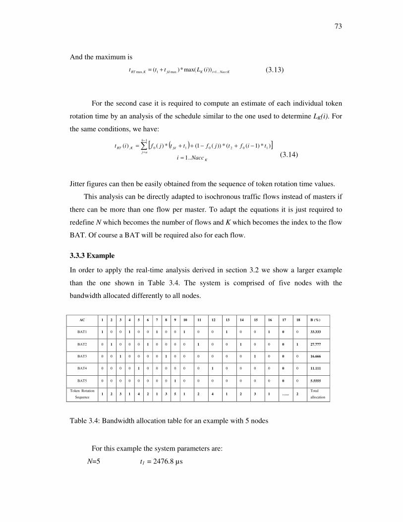
73
And the maximum is
NaccKiKfdKRTiLttt ...1max1max, ))(max(*)( =+= (3.13)
For the second case it is required to compute an estimate of each individual token
rotation time by an analysis of the schedule similar to the one used to determine LK(i). For
the same conditions, we have:
( )[ ]
K
b
aj
fdKRT
Nacci
tiftjfttjfit
..1
)*)1((*))(1(*)()(1
102010,
=
−+−++= ∑−
=
(3.14)
Jitter figures can then be easily obtained from the sequence of token rotation time values.
This analysis can be directly adapted to isochronous traffic flows instead of masters if
there can be more than one flow per master. To adapt the equations it is just required to
redefine N which becomes the number of flows and K which becomes the index to the flow
BAT. Of course a BAT will be required also for each flow.
3.3.3 Example
In order to apply the real-time analysis derived in section 3.2 we show a larger example
than the one shown in Table 3.4. The system is comprised of five nodes with the
bandwidth allocated differently to all nodes.
For this example the system parameters are:
N=5 t1 = 2476.8 µs
AC 1 2 3 4 5 6 7 8 9 10 11 12 13 14 15 16 17 18 B (%)
BAT1 1 0 0 1 0 0 1 0 0 1 0 0 1 0 0 1 0 0 33.333
BAT2 0 1 0 0 0 1 0 0 0 0 1 0 0 1 0 0 0 1 27.777
BAT3 0 0 1 0 0 0 0 1 0 0 0 0 0 0 1 0 0 0 16.666
BAT4 0 0 0 0 1 0 0 0 0 0 0 1 0 0 0 0 0 0 11.111
BAT5 0 0 0 0 0 0 0 0 1 0 0 0 0 0 0 0 0 0 5.5555
Token Rotation
Sequence 1 2 3 1 4 2 1 3 5 1 2 4 1 2 3 1 …... 2
Total
allocation
Table 3.4: Bandwidth allocation table for an example with 5 nodes
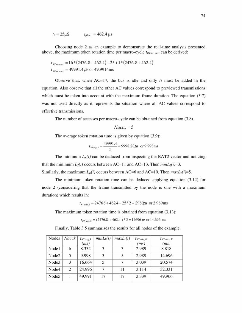
74
t2 = 25µS tfdmax = 462.4 µs
Choosing node 2 as an example to demonstrate the real-time analysis presented
above, the maximum token rotation time per macro-cycle tRTmc max can be derived:
( ) ( )
49.9914msor s49991.4
4.4628.2476*1254.4628.2476*16
max
max
µ=
++++=
RTmc
RTmc
t
t
Observe that, when AC=17, the bus is idle and only t2 must be added in the
equation. Also observe that all the other AC values correspond to previewed transmissions
which must be taken into account with the maximum frame duration. The equation (3.7)
was not used directly as it represents the situation where all AC values correspond to
effective transmissions.
The number of accesses per macro-cycle can be obtained from equation (3.8).
52 =Nacc
The average token rotation time is given by equation (3.9):
9.998msor s9998.285
49991.42, µ==RTavgt
The minimum LK(i) can be deduced from inspecting the BAT2 vector and noticing
that the minimum L2(i) occurs between AC=11 and AC=13. Then minL2(i)=3.
Similarly, the maximum LK(i) occurs between AC=6 and AC=10. Then maxL2(i)=5.
The minimum token rotation time can be deduced applying equation (3.12) for
node 2 (considering that the frame transmitted by the node is one with a maximum
duration) which results in:
ms 2.989or 29892*254.4628.24762min, stRT µ=++=
The maximum token rotation time is obtained from equation (3.13):
ms 14.696or 146965*) 462.4 2476.8(2max, st RT µ=+=
Finally, Table 3.5 summarises the results for all nodes of the example.
Nodes Nacck tRTavg,k
(ms)
minLk(i) maxLk(i) tRTmin,K
(ms)
tRTmax,K
(ms)
Node1 6 8.332 3 3 2.989 8.818
Node2 5 9.998 3 5 2.989 14.696
Node3 3 16.664 5 7 3.039 20.574
Node4 2 24.996 7 11 3.114 32.331
Node5 1 49.991 17 17 3.339 49.966

75
Table 3.5:Real-time analysis results for the example of Table 3.4 The nodes transmission schedule for this example was chosen only to clarify the
application of the derived real-time analysis. It shows a possible asymmetric bandwidth
distribution among the 5 nodes that was not possible with the common circular token
rotation. For example, in this case, the bandwidth allocated to node 1 has been
substantially improved, with a maximum blocking caused by the token circulation of
8.818ms. With circular token rotation, this blocking would be 14.969ms if the same
operational parameters were used.
Table 3.5 also allows deducing the maximum jitter in the token arrivals, which is
substantial for nodes with less bandwidth but smaller for nodes with high bandwidth,
which are the most demanding ones.
3.3.4 Adapting the classic VTPE frame
In order to implement this new feature in VTPE the real value of the access counter must
be sent inside each frame. This is because the access counter can be different of the node
address due to the fact that a node can be visited more than once by token rotation time. A
little modification in the definition of the VTPE frame should be done. The new VTPE
frame is shown in the Figure 3.7.
Figure 3.7: New VTPE frame.
In Figure 3.7 the AC field is one byte long, the reserved field, R, is two bytes long
and all other fields remain according to Section 3.2. Being AC one byte long than 256
different values per token rotation time can be addressed and this value is enough for the
aimed application of VTPE.
3.4. Conclusions
The VTPE classic approach in which a master sends just a frame per token rotation was the
first version presented in this chapter. It is simple and easy to be implemented. However in
this approach there is no prioritized bandwidth allocation among the nodes and this lack
can cause blocking depending of the number of masters in the system. If this number

76
increases this approach becomes unsuited for application such as multimedia because it can
lead to significant blocking. The improved VTPE approach alleviates the blocking caused
by the circular token rotation because the token may visit the same node more than once in
each rotation. This improvement gives higher priority to the nodes that are source of
isochronous traffic or, at least, gives them the right to access the network more often than
regular nodes. This more frequent access can be accomplished with an almost regular
period, which may be different from node to node and which seems adequate for
isochronous traffic. Then the bandwidth can be differently allocated to the masters
depending on their communication needs. This technique does not require significant
changes to the “normal” scheme, thus inheriting its advantages and being suited to VTPE
and P-NET protocols. By making a careful schedule of the traffic and an adequate choice
of parameters it is possible to limit the jitter of periodic traffic. Isochronous traffic flows
can then be transmitted. However, some additional work must yet be done on this issue.

77
Chapter 4
The VTPE-hBEB Protocol
4.1 Introduction
Despite the increasing use of switches to interconnect Ethernet devices, the vast majority
of Ethernet networks still operate in heterogeneous environments. Figure 4.1 shows a
heterogeneous environment with Ethernet Switching Hubs interconnecting both
independent node stations and Ethernet Repeater Hubs with multiple interconnected node
stations (equivalent to shared Ethernet segments).
Figure 4.1: Heterogeneous Ethernet environment.
In such heterogeneous environments, the Switching Hubs impose separate collision
domains at each port (network segmentation), allowing the implementation of service

78
policies with different priorities. However, within each of the collision domains (i.e.,
among node stations interconnected by each Repeater Hub), the network still operates in
the traditional shared Ethernet mode; that is, collisions are solved by means of a
probabilistic contention resolution algorithm, i.e., the medium access is inherently non-
deterministic.
Several approaches and techniques have been developed to provide real-time
behaviour to Ethernet-supported applications. However, few of those techniques allow
standard devices to coexist with enhanced stations in the same network segment. Relevant
exceptions such as [9] and [35] have strong limitations related to the number of allowed
real-time stations [9] or the requirement for the use of specific hardware [35].
This chapter proposes a shared Ethernet deterministic architecture, able to
interconnect sensors, controllers and actuators at the field level, allowing the coexistence
of standard Ethernet devices with enhanced (real-time) devices. Such solution is based on
the control of the medium access right, by means of the virtual token passing technique
among enhanced stations, complemented by the underlying prioritization mechanism, the
hBEB algorithm. Such underlying mechanism, as presented in the Chapter 2, guarantees
that, whenever an enhanced (real-time) station is contending for the bus access, it will be
able to access the bus prior to any other station. Thus, it enables the traffic separation
between standard and enhanced (real-time) stations, being able to guarantee real-time
communication in unconstrained traffic environments. This proposal has been named
Virtual Token Passing Ethernet over hBEB algorithm or VTPE-hBEB for short.
The development of this proposal joining VTPE with hBEB resulted from a fruitful
collaboration with the University of Porto, Faculty of Engineering. The team in Porto was
responsible for the validation through simulation of some of the proposals discussed in this
thesis. A PhD Thesis including some of the correpondent results can be found in [102].
The remaining of this chapter is as follows: Section 4.2 presents two VTPE-hBEB
proposals: a general one considering that VTPE-hBEB can be implemented in any Ethernet
controller that supports the BEB algorithm disabling and interrupts, and an adaptation
leading to an implementation of VTPE-hBEB in a specific Ethernet controller. Finally,
section 4.3 presents the conclusions.
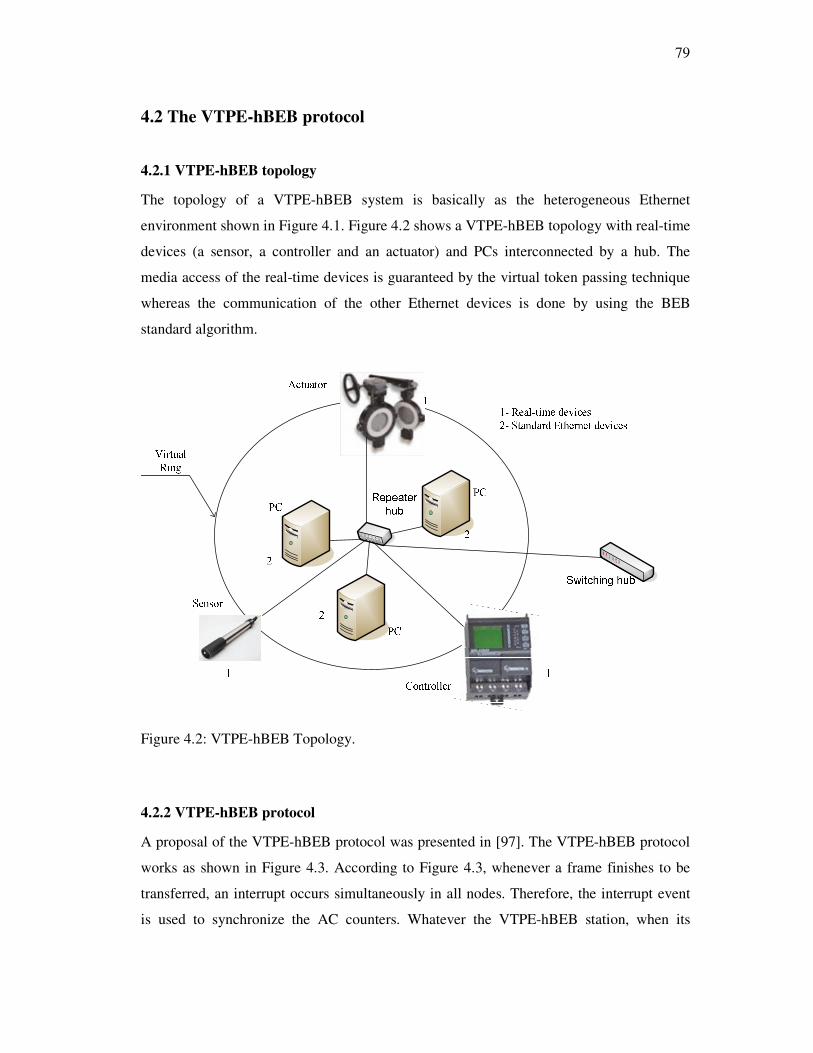
79
4.2 The VTPE-hBEB protocol
4.2.1 VTPE-hBEB topology
The topology of a VTPE-hBEB system is basically as the heterogeneous Ethernet
environment shown in Figure 4.1. Figure 4.2 shows a VTPE-hBEB topology with real-time
devices (a sensor, a controller and an actuator) and PCs interconnected by a hub. The
media access of the real-time devices is guaranteed by the virtual token passing technique
whereas the communication of the other Ethernet devices is done by using the BEB
standard algorithm.
Figure 4.2: VTPE-hBEB Topology.
4.2.2 VTPE-hBEB protocol
A proposal of the VTPE-hBEB protocol was presented in [97]. The VTPE-hBEB protocol
works as shown in Figure 4.3. According to Figure 4.3, whenever a frame finishes to be
transferred, an interrupt occurs simultaneously in all nodes. Therefore, the interrupt event
is used to synchronize the AC counters. Whatever the VTPE-hBEB station, when its

80
Access Counter (AC) is equal to the Node address (NA), it means that the station is
holding the token. If the station has something to transmit, the hBEB algorithm will
immediately start, guaranteeing that the station will win the medium access in a bounded
time.
If the station holding the virtual token does not have any message to be transferred,
it will allow Ethernet standard stations to contend for accessing the bus, during a time
interval t2. If the bus remains idle during t2, an interrupt will be generated in all the stations
and all the AC counters will be incremented, which corresponds to an implicit token
passing.
Interrupt
Increment
AC
AC=NA
?
Yes No
Has message to
be transmittedSet
t2
No
Bus
Idle
t2
elapsed?
Yes No
Set
t3
t3
Expired?
Set
H-BEB
Algorithm
h-BEB
Finished ?
Message being
transferred ?
Message
Transf.
Finished?Bus
Idle during
More than
9.6µs
Yes
No
Yes
No
Yes
No
Yes No
No
Yes
NoYes
1
12
34
5
6
7
Nothing happens during
t2, i.e., bus is idle, no
station is transmitting.
1
2 Collisions or
transmission of
a message
were detected
3 Collisions were solved
and a message is
being transmitted.
Collisions not yed
solved.
4
No VTPE/h-BEB node is
involved in the colisions,
otherwise the contention
interval would be shorter.
5
Collision resolution still in
progress. It is not possible
to know if a VTPE/h-BEB
node is involved or not.
6
7 No VTPE/h-BEB node is
involved otherwise
contention resolution would
be solved in less than t3.
Figure 4.3: Control Flow Summary – VTPE-hBEB.
If an Ethernet standard station tries to transmit during the time interval t2, two
different situations can arise: either the message is normally transmitted or a collision
81
resolution procedure starts. If a transmission occurs, then the algorithm just waits for the
interrupt at the end of the message transfer. If a collision resolution starts, then it can be
either generated just by standard Ethernet stations or it can also include an active hBEB
station holding the token. The first scenario, i.e., a collision involving just standard
Ethernet stations, can be detected if a bus idle occurs with duration greater than 51,2µs
(slot time duration at 10Mbps). In such case, the VTPE-hBEB stations can pass the virtual
token as the hBEB station that is holding the token has nothing to transmit.
As deduced in [9] and also as presented in Chapter 2, the hBEB algorithm solves
collisions in a bounded time, or it eventually discards the message. This enables the
definition of a time interval t3, greater than the hBEB collision resolution interval. If a
message does not start to be transferred during the t3 interval, then a collision between
messages from multiple standard Ethernet stations has occurred (as the hBEB collision
resolution algorithm would have succeeded during that interval). If the t3 interval expires,
it is then possible to pass again the token and thus an interrupt is generated.
The VTPE-hBEB frame format is the same as the VTPE discussed in the Section
3.3.3 and no modification is necessary in it.
4.2.3 Timing analysis
In this section, it is presented the timing analysis of an Ethernet network interconnecting
multiple VTPE-hBEB stations with Ethernet standard stations. This analysis clearly
illustrates the real-time behaviour of the proposed VTPE-hBEB architecture.
Consider a network with n VTPE-hBEB stations, with addresses ranging from 1 to
N. Each VTPE-hBEB station accesses the network according to the VTPE-hBEB scheme,
i.e., first station 1, then station 2, 3,… until station N, and then again station 1, 2,…N. The
standard Ethernet stations implement the traditional BEB collision resolution algorithm.
First of all, consider a two-collision scenario. In such case, the maximum delay to
transfer a real-time message, when the VTPE-hBEB station is holding the token, is
illustrated in Figure 4.4.

82
Figure 4.4: Collision scenario solved by the hBEB collision resolution algorithm.
According to the VTPE-hBEB scheme, such station transmits its message using the
hBEB algorithm; that is, it always tries to transmit its message in the first time slot.
Therefore, when a VTPE-hBEB station holding the token has a message ready to be
transferred (PA), it will wait an Inter Frame Gap (I1: 12 byte times) before starting to
transmit. If a collision occurs during the transfer of the first 64 bytes of message PA, a
jamming sequence will be broadcasted (J1: 4 byte times). Afterwards, the station will wait
again during an Inter Frame Gap (I2: 12 byte times) and, according to the hBEB algorithm,
it will immediately start to transmit its message. If a second collision occurs, a new
jamming sequence (J2) will be broadcasted and station A will wait again for the Inter
Frame Gap (I3), before starting to transmit. The cumulative result (from t0 up to the
beginning of the third attempt) is 160 bytes or 0.128ms (at a 10 Mbps bit rate). The
maximum time that a VTPE-hBEB station holding the token will wait before starting to
transfer a message, or eventually to discard it, is 0.960ms as shown in Table 4.1.
Retry Number
Max delay (# slots)
Max cumulative delay (# slots)
Max delay (ms)
1 1 1 0,064
2 1 2 0,128
3 1 3 0,192
…
9 1 9 0,576
10 1 10 0,640
…
14 1 14 0,896
15 1 15 0,960
16 discard frame
Table 4.1: Maximum delay to start transferring a message in the hBEB algorithm.
Table 4.1 shows that the hBEB algorithm solves collisions in a bounded time, or it
eventually discards the message. Therefore, it is of utmost importance to focus on the
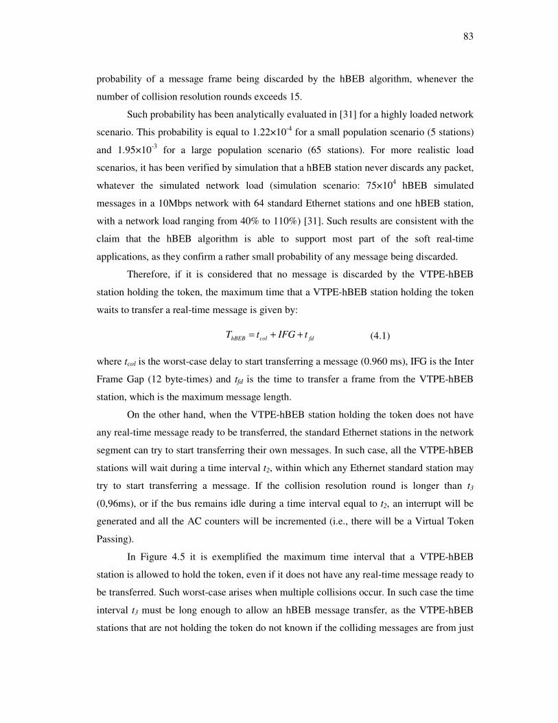
83
probability of a message frame being discarded by the hBEB algorithm, whenever the
number of collision resolution rounds exceeds 15.
Such probability has been analytically evaluated in [31] for a highly loaded network
scenario. This probability is equal to 1.22×10⁻⁴ for a small population scenario (5 stations)
and 1.95×10⁻³ for a large population scenario (65 stations). For more realistic load
scenarios, it has been verified by simulation that a hBEB station never discards any packet,
whatever the simulated network load (simulation scenario: 75×104 hBEB simulated
messages in a 10Mbps network with 64 standard Ethernet stations and one hBEB station,
with a network load ranging from 40% to 110%) [31]. Such results are consistent with the
claim that the hBEB algorithm is able to support most part of the soft real-time
applications, as they confirm a rather small probability of any message being discarded.
Therefore, if it is considered that no message is discarded by the VTPE-hBEB
station holding the token, the maximum time that a VTPE-hBEB station holding the token
waits to transfer a real-time message is given by:
fdcolhBEB tIFGtT ++= (4.1)
where tcol is the worst-case delay to start transferring a message (0.960 ms), IFG is the Inter
Frame Gap (12 byte-times) and tfd is the time to transfer a frame from the VTPE-hBEB
station, which is the maximum message length.
On the other hand, when the VTPE-hBEB station holding the token does not have
any real-time message ready to be transferred, the standard Ethernet stations in the network
segment can try to start transferring their own messages. In such case, all the VTPE-hBEB
stations will wait during a time interval t2, within which any Ethernet standard station may
try to start transferring a message. If the collision resolution round is longer than t3
(0,96ms), or if the bus remains idle during a time interval equal to t2, an interrupt will be
generated and all the AC counters will be incremented (i.e., there will be a Virtual Token
Passing).
In Figure 4.5 it is exemplified the maximum time interval that a VTPE-hBEB
station is allowed to hold the token, even if it does not have any real-time message ready to
be transferred. Such worst-case arises when multiple collisions occur. In such case the time
interval t3 must be long enough to allow an hBEB message transfer, as the VTPE-hBEB
stations that are not holding the token do not known if the colliding messages are from just

84
Ethernet standard stations, or if there is also a message from a VTPE-hBEB station holding
the token. In the latter, the time interval t3 guarantees that the VTPE-hBEB station that
holds the token will be able to transmit its message and an interrupt will occur when the
message transfer is finished. Otherwise, if the collision resolution is not solved during the
time interval t3, it means that the collisions are occurring just among standard Ethernet
stations. Therefore, an interrupt will be generated after t3 and the next VTPE-hBEB station
in the logical ring will be able to contend for the medium access.
Figure 4.5: VTPE-hBEB token holding time.
The worst-case for the token holding time occurs when, at instant (t3 - ε), a standard
Ethernet station starts to transmit a 1518-byte message (tover), which is the longest message
that can be transferred in an Ethernet network.
Therefore, the maximum time that a VTPE-hBEB station may hold the token is
given by:
overTH ttT += 3 (4.2)
As the token rotation time is the time interval between two consecutive token visits
to a particular station, the worst-case token rotation time, denoted as TRT, is given by:
THTNTRT *= (4.3)
where TTH is as defined in equation 4.2. The value TRT represents the worst-case time
interval between two consecutive token arrivals to any VTPE-hBEB station (M=1… N).
4.2.4 Adapting the VTPE-hBEB proposal
The VTPE-hBEB protocol essentially requires both interrupt and BEB algorithm disabling
support in order to be implemented in COTS hardware. Due to the fact that the BEB
algorithm disabling does not belong to the IEEE 802.3 standard, this feature is not usually
supported in the Ethernet controllers aimed for general purpose applications. In fact, when

85
this work has been started, there was a lack of Ethernet controllers able to support backoff
disabling and only the CS8900A-CQ [88] Ethernet controller was found. However the
BEB disabling feature is becoming common in those Ethernet controllers aimed for
embedded application. More recently some new embedded Ethernet controllers, able to
support backoff disabling, were launched such as the ENC28J60 from Microchip [89] and
the CP2200-GQ and CP2201-GM from Silabs [90]. The BEB disabling support seems now
to be a common feature in the Ethernet controllers aimed for embedded application.
The CS8900A-CQ controller allows BEB disabling but interrupt is not well
supported when it is used with an 8-bit host processor. According to Ayres [91] the polling
method to a receive event register must be used instead of the interrupt for sensing and
getting received frames. Eady [94] points out that CS8900A-CQ will work in 8-bit mode
since the Ethernet traffic is kept very light. However VTPE-hBEB is aimed to be used
either in small processing power controllers and or in powerful ones as well, working in
very loaded traffic environments. These drawbacks imply some changes in the proposal
presented in Section 4.2.2 and in the hardware as well.
Our hardware solution uses a couple of CS8900A-CQ/microcontroller per node,
that is, one couple of CS8900A-CQ/microcontroller runs the VTPE-hBEB and the other
runs the application. A detailed explanation of hardware will be presented in the Chapter 5.
A flowchart for adaptation of VTPE-hBEB proposal is shown in Figure 4.6.

86
Figure 4.6: VTPE flowchart for a dual Ethernet controller implementation.
As shown in Figure 4.6, VTPE-hBEB runs in Microcontroller 1 while the application runs
in Microcontroller 2. According to Figure 4.6, the Microcontroller 1 (left side) starts a
timer with t1 and polls continuously looking for received Ethernet frames in the receive
event register. Whenever a new frame is received the microcontroller initiates the
transference and the frame decoding immediately. The frame decoding process checks the
access counter (AC) in the VTPE-hBEB header field (the same as the VTPE header field –
Section 3.3.3), refreshes its own AC with the received AC, increases AC and checks AC
against its NA or BAT table. If (AC=NA or AC=BAT(i)) a level logic transition is
signalised in a pin of Microcontroller 1. This pin is the source of interruption and then it is
tied to an external interrupt pin of Microcontroller 2. If the application in the
Microcontroller 2 has a ready frame to transmit it starts transmitting as soon as the
interrupt is serviced and the bus is free, otherwise, having nothing to transmit, t1 is allowed

87
to timeout and the next node of the virtual ring gets the right to access the bus according to
the VTPE fashion.
In order to evaluate the timing behaviour, targeting the best network performance, it
is considered that the application produces and loads a ready frame into the CS8900A-CQ
until the last but one byte and that it waits for the interrupt. When interrupted, the two
remaining bytes of the ready frame are loaded into the CS8900A-CQ and the frame is
dispatched on the bus as soon as the bus is free.
In order to find the bounded VTPE-hBEB arbitration time, it is required to
determine the elapsed time since the Microcontroller 1 senses a received frame until the
Microcontroller 2 starts transmitting a frame on the bus. This time can be obtained by
measuring the time intervals involved in the VTPE-hBEB implementation. These time
intervals are as follows:
• The time spent in the polling cycle, tpoll, in Microcontroller 1;
• The decoding time of Microcontroller 1, td. The decoding time td is the sum
of the time to transfer and check a received frame until checking the VTPE-
hBEB header field, the time to get the AC of the received frame and to
refresh the node AC variable, the time to increase AC and to compare to NA
or BAT table and the time signalising the interrupt in the pin of
Microcontroller 1.
• The interrupt service routine time, tisr, in Microcontroller 2.
The VTPE-hBEB arbitration time is the sum of the three time intervals reported
above and it is represented by equation (4.4).
isrdpollVTPE tttt ++= (4.4)
In order to measure each time interval of equation (4.4) a method commonly used is
to count the amount of assembly instructions provided by the compiler in the assembly list
and to convert the figure to machine cycle times of the used microcontroller. This method
and the time results are detailed in the Chapter 6.

88
4.3 Conclusions
As referred in the section 4.1 the major motivation of this chapter is to propose a solution
enabling the support of real-time communications in shared Ethernet environments, where
Ethernet standards devices can coexist with multiple enhanced devices.
To address this problem, it was proposed a solution based on the Virtual Token-
Passing procedure, where an underlying high priority Binary Exponential Backoff (hBEB)
algorithm guarantees the medium access right to the VTPE station that is holding the
token. This allows Ethernet standard devices to coexist with multiple VTPE enhanced
stations, imposing a higher priority for the transfer of VTPE-hBEB related traffic and
guaranteeing the required traffic separation. Initially it was presented a general proposal
considering that the VTPE-hBEB protocol can be implemented in any Ethernet controller
that supports the BEB algorithm disabling. After, an adaptation was proposed considering
its implementation with an available Ethernet controller. Also it was presented the timing
analysis of VTPE-hBEB for a shared Ethernet segment with a moderate number of nodes.
In this case the token rotation can be in the order of several milliseconds. This figure seems
adequate for real-time applications in the automation domain.
89
Chapter 5
VTPE and VTPE-hBEB Implementations
5.1 Introduction
The virtual token passing implementation in the P-NET protocol allows each master to
identify if an in progress frame is coming from a master or a slave, only by reading the first
byte of the frame being transmitted. This procedure allows the masters to always maintain
their access counters synchronised. Even though increasing the processing overhead of the
masters due to large number of frames that must be read, this procedure allows to reduce
further processing, because they must only accept and perform further processing if the in
progress frame is meaningful.
The above procedure can not be implemented using current standard Ethernet
controllers because they don’t support the facility of reading the content of frames before
the end of their transmissions. Then any implementation of the virtual token passing
principle using standard Ethernet controllers requires that any transmitted frame must be
accepted first and checked after by a software layer over the Ethernet layer.
To implement the VTPE or VTPE-hBEB protocol allowing the masters to identify
the frames during their transmission requires a special Ethernet controller. An
implementation of the Ethernet controller using an IP core solves this because the frame
decoding and the virtual token passing procedure can be executed during the frame
transmission.
The implementation of VTPE or VTPE-hBEB using a standard Ethernet controller
is basically the same in terms of hardware. However a slight distinction can be pointed out
according to some Ethernet controller features. VTPE can be implemented using any

90
controller but VTPE-hBEB can only be implemented if the Ethernet controller offers BEB
disabling support.
This chapter discusses two implementations for proof of concept of VTPE and
VTPE-hBEB protocols based on standard Ethernet controllers. The first one uses a single
Ethernet controller per node and the other uses a dual Ethernet controller architecture. It is
also presented a proposal for future implementation of VTPE and VTPE-hBEB based on
an IP core.
The remaining of this chapter is as follows: Section 5.2 presents an implementation
of VTPE based on a single Ethernet controller. Section 5.3 presents an implementation of
VTPE and VTPE-hBEB proposals based on a dual Ethernet controller architecture. Section
5.4 presents a proposal for the implementation of VTPE and VTPE-hBEB using an IP core
and section 5.5 presents the conclusions.
5.2 Implementation based on single ethernet controller
The implementation discussed in this section is based on a classic Realtek RTL8019AS
Ethernet controller [93]. It is aimed only for VTPE because RTL8019AS doesn’t support
the BEB algorithm disabling. The microcontroller used is the PIC 18F458 [89], working at
40 MHz frequency.
5.2.1 System architecture based on single ethernet controller
An implementation of the VTPE protocol using a single Ethernet controller was carried out
and reported in [80]. The VTPE system architecture based on single Ethernet controller is
shown in Figure 5.1.
Master
1Master
2
Master
3
Virtual
Token
HUB
Figure 5.1: VTPE system architecture
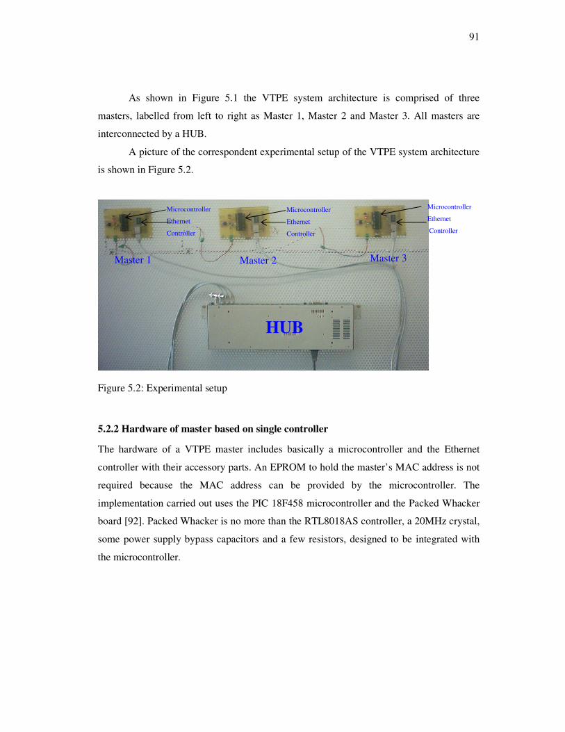
91
As shown in Figure 5.1 the VTPE system architecture is comprised of three
masters, labelled from left to right as Master 1, Master 2 and Master 3. All masters are
interconnected by a HUB.
A picture of the correspondent experimental setup of the VTPE system architecture
is shown in Figure 5.2.
Figure 5.2: Experimental setup
5.2.2 Hardware of master based on single controller
The hardware of a VTPE master includes basically a microcontroller and the Ethernet
controller with their accessory parts. An EPROM to hold the master’s MAC address is not
required because the MAC address can be provided by the microcontroller. The
implementation carried out uses the PIC 18F458 microcontroller and the Packed Whacker
board [92]. Packed Whacker is no more than the RTL8018AS controller, a 20MHz crystal,
some power supply bypass capacitors and a few resistors, designed to be integrated with
the microcontroller.
HUB
Microcontroller
Ethernet
Controller
Microcontroller
Ethernet
Controller
Master 1 Master 2 Master 3
Microcontroller
Ethernet
Controller

92
Packed
WhackerPIC
18F458
SA0:SA4
RSTDRV
IOW
IORB
EED0
INT0
RE2
To HUB
RB0
RA1
RE0
RE1
SD0:SD7 RD0:RD7
RB1:RB5
Figure 5. 3: Hardware of a VTPE master
Figure 5. 3 shows a diagram with the main connections between the RTL8019AS
and the PIC18F458 microcontroller. The RTL8019AS controller was originally designed
for major Ethernet applications in desktop personal computers and some of its functionality
will be useless when attached to the 8-bit microcontroller. This useless functionality allows
the simplification of the hardware, namely:
• The EPROM can be unnecessary. This feature allows simplifying the
hardware and makes easier the modification of the MAC address value;
• Only 5 addresses lines (SA0 – SA4) are necessary to manage all the
RTL8019AS internal registers available for operation in 8-bit mode;
• Only 8 data lines (SD0 - SD7) are necessary to transfer data between the
RTL8019AS and the processor/microcontroller.
In order to prevent the RTL8019AS from expecting data from an external
EEPROM at initialization, the RTL8019AS’s EEDO (EEPROM Data Output) line must be
low at startup and left low forever.
The RTL8019AS raises the INT0 I/O line to signal to the microcontroller the
reception of an Ethernet frame. The IOW and IORB are I/O lines that allow the
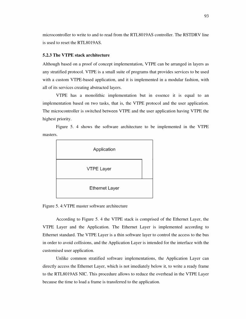
93
microcontroller to write to and to read from the RTL8019AS controller. The RSTDRV line
is used to reset the RTL8019AS.
5.2.3 The VTPE stack architecture
Although based on a proof of concept implementation, VTPE can be arranged in layers as
any stratified protocol. VTPE is a small suite of programs that provides services to be used
with a custom VTPE-based application, and it is implemented in a modular fashion, with
all of its services creating abstracted layers.
VTPE has a monolithic implementation but in essence it is equal to an
implementation based on two tasks, that is, the VTPE protocol and the user application.
The microcontroller is switched between VTPE and the user application having VTPE the
highest priority.
Figure 5. 4 shows the software architecture to be implemented in the VTPE
masters.
Figure 5. 4:VTPE master software architecture
According to Figure 5. 4 the VTPE stack is comprised of the Ethernet Layer, the
VTPE Layer and the Application. The Ethernet Layer is implemented according to
Ethernet standard. The VTPE Layer is a thin software layer to control the access to the bus
in order to avoid collisions, and the Application Layer is intended for the interface with the
customised user application.
Unlike common stratified software implementations, the Application Layer can
directly access the Ethernet Layer, which is not imediately below it, to write a ready frame
to the RTL8019AS NIC. This procedure allows to reduce the overhead in the VTPE Layer
because the time to load a frame is transferred to the application.

94
The VTPE suite is written in the C programming language using the Custom
Computer Services C Compiler (CCS). The code implementing for each layer resides in a
separate source file, while the services and APIs (Application Programming Interfaces) are
defined through header/include files. The source and header files are presented in the
media attached to this thesis.
Each layer of the VTPE architecture is presented as follows.
The Ethernet Layer
This version of the Ethernet Layer has been specifically written to make use of the Realtek
RTL8019AS NIC. RTL8019AS is a NE2000 compatible NIC that implements both the
Ethernet physical (PHY) and MAC layers. The on-chip SRAM memory of RTL8019AS is
used as a holding buffer for an incoming frame until the VTPE layer reads it, and for an
outgoing frame until the master dispatches it to the bus. In order to control the outgoing
traffic according to the VTPE protocol only one frame can be stored in the RTL8019AS at
a time. This is because VTPE can not control the instant to start transmiting each frame
when more than one is loaded in the RTL8019AS. On the other hand, only one received
frame can be stored at a time to avoid overflow in the receive buffer memory of the
RTL8019AS. In order to understand the RTL8019AS set up a lot of information on
internal registers is required. A detailed description of the RTL8019AS controller can be
found in the datasheet [93]. A detailed description of the step-by-step style on how to write
code to RTL8019AS can be found in [94]. The application notes for National DP8390
Ethernet controller are also very useful for the development [95] [96].
The Ethernet Layer is implemented by means of the rtl8019as.c source file. The rtl8019as.c
source file has a set of functions to put the RTL8019AS ready to receive and transmit
frames. Table 5. 1 summarises the functions for RTL8019AS initialisation.
Module/
Dependence
Function Purpose
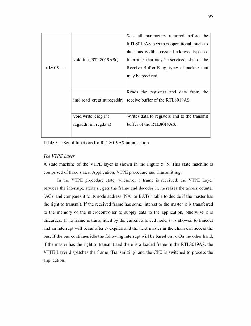
95
void init_RTL8019AS()
Sets all parameters required before the
RTL8019AS becomes operational, such as
data bus width, physical address, types of
interrupts that may be serviced, size of the
Receive Buffer Ring, types of packets that
may be received.
int8 read_creg(int regaddr)
Reads the registers and data from the
receive buffer of the RTL8019AS.
rtl8019as.c
void write_creg(int
regaddr, int regdata)
Writes data to registers and to the transmit
buffer of the RTL8019AS.
Table 5. 1:Set of functions for RTL8019AS initialisation.
The VTPE Layer
A state machine of the VTPE layer is shown in the Figure 5. 5. This state machine is
comprised of three states: Application, VTPE procedure and Transmitting.
In the VTPE procedure state, whenever a frame is received, the VTPE Layer
services the interrupt, starts t1, gets the frame and decodes it, increases the access counter
(AC) and compares it to its node address (NA) or BAT(i) table to decide if the master has
the right to transmit. If the received frame has some interest to the master it is transferred
to the memory of the microcontroller to supply data to the application, otherwise it is
discarded. If no frame is transmitted by the current allowed node, t1 is allowed to timeout
and an interrupt will occur after t1 expires and the next master in the chain can access the
bus. If the bus continues idle the following interrupt will be based on t2. On the other hand,
if the master has the right to transmit and there is a loaded frame in the RTL8019AS, the
VTPE Layer dispatches the frame (Transmitting) and the CPU is switched to process the
application.

96
Figure 5. 5: Path of application to the VTPE
The VTPE Layer is implemented by the vtpe.c source file, which includes a set of
functions to execute the VTPE procedure. Table 5. 2 shows the set of functions regarding
this Layer.
Module/
Dependence
Function Purpose
void ext_int()
This function is an Interrupt Service Routine
(ISR). Then, whenever RTL8019AS rises on
the INT0 pin, the ISR sets t1, and dispatches a
previously loaded frame if AC is equal to NA
or BAT(i). After, AC is increased and
compared with M. If AC=M, it is preset to 1,
otherwise the ISR is terminated.
vtpe.c
void isrt1 ()
This function is another Interrupt Service
Routine. Whenever t1 expires, the ISR sets t1
again, and dispatches a previously loaded frame
if AC is equal to NA or BAT(i). After AC is
increased and compared to M. If AC=M, it is
preset to 1, otherwise the ISR is terminated.
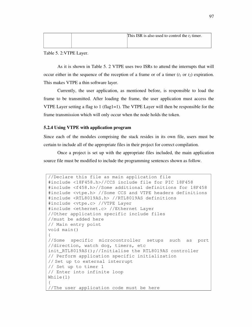
97
This ISR is also used to control the t2 timer.
Table 5. 2:VTPE Layer.
As it is shown in Table 5. 2 VTPE uses two ISRs to attend the interrupts that will
occur either in the sequence of the reception of a frame or of a timer (t1 or t2) expiration.
This makes VTPE a thin software layer.
Currently, the user application, as mentioned before, is responsible to load the
frame to be transmitted. After loading the frame, the user application must access the
VTPE Layer setting a flag to 1 (flag1=1). The VTPE Layer will then be responsible for the
frame transmission which will only occur when the node holds the token.
5.2.4 Using VTPE with application program
Since each of the modules comprising the stack resides in its own file, users must be
certain to include all of the appropriate files in their project for correct compilation.
Once a project is set up with the appropriate files included, the main application
source file must be modified to include the programming sentences shown as follow.
//Declare this file as main application file
#include <18F458.h>//CCS include file for PIC 18F458
#include <f458.h>//Some additional definitions for 18F458
#include <vtpe.h> //Some CCS and VTPE headers definitions
#include <RTL8019AS.h> //RTL8019AS definitions
#include <vtpe.c> //VTPE Layer
#include <ethernet.c> //Ethernet Layer
//Other application specific include files
//must be added here
// Main entry point
void main()
{
//Some specific microcontroller setups such as port
//direction, watch dog, timers, etc
init_RTL8019AS();//Initialise the RTL8019AS controller
// Perform application specific initialization
// Set up to external interrupt // Set up to timer 1
// Enter into infinite loop
While(1)
{
//The user application code must be here

98
//The application produces and loads a VTPE frame
//When the frame is loaded flag1 is set to 1
flag1=1;//Signalise to VTPE that a frame wait for
//transmission
While(flag1);//waits for the transmission right
}
5.3 Implementation based on a dual ethernet controller architecture
5.3.1 The dual ethernet controller architecture
The VTPE implementation based on a dual Ethernet controller architecture uses two
microcontroller/Ethernet-controllers per master as shown in Figure 5.6. The
microcontroller is the PIC 18F458 working at a 40 MHz frequency and the Ethernet
controller is the CS8900A-CQ [88]. The dual Ethernet controller architecture
implementation allows to run either VTPE or VTPE-hBEB because the referred Ethernet
controller allows BEB algorithm disabling.
The main reasons for an implementation based on a dual Ethernet controller
architecture are:
• Resolving the CS8900A-CQ interrupt problem when it works in 8-bit mode;
• Increasing the processing power because it uses two microcontrollers;
• Separating the VTPE or VTPE-hBEB from the application;
• Reducing the processing overhead in the microcontroller that hosts the
application due to:
o The application is interrupted only when the master has the right to
access the bus;
o The broadcasting traffic is not necessary for all frames because
unicast and multicast addressing can be used.
An essential feature of the Ethernet controller for VTPE-hBEB implementation is
to allow the BEB algorithm disabling. The CS8900A-CQ controller was the unique found
with support to this feature when this work has been started. However the CS8900A-CQ

99
controller doesn’t support interrupt in 8-bit mode and interrupt is a very important issue for
protocol synchronisation either for VTPE or VTPE-hBEB. According to the application
note AN181 [91], when the CS8900A-CQ operates in 8-bit mode, it is mandatory to use
the polling method instead of interrupts, to access the receive event register. Our hardware
uses two CS8900A-CQ/microcontrollers per master in order to overcome this drawback.
One of the CS8900A-CQ/microcontroller sets is responsible to run VTPE or VTPE-hBEB
(bus arbitration) and to generate an interrupt. The other hosts the application.
Figure 5.6: Dual Ethernet controller architecture.
Recently some new Ethernet controllers with support to BEB disabling and
intended for embedded applications were launched in the market. According to our best
knowledge there is no problem reported with the interrupt support in 8-bit mode. Then
these controllers would also be suitable for VTPE-hBEB implementation using a single
controller per node instead of two. The ENC28J60 from Microchip [89], and the CP2200-
GQ and CP2201-GM from Silabs [90] are just some examples.
An experimental setup for the dual Ethernet controller was developed during this
work. Figure 5. 7 shows a picture of the actual setup.
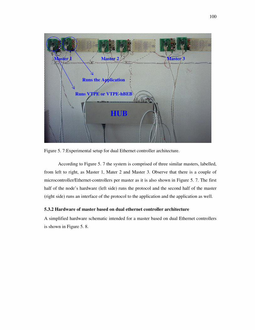
100
Figure 5. 7:Experimental setup for dual Ethernet controller architecture.
According to Figure 5. 7 the system is comprised of three similar masters, labelled,
from left to right, as Master 1, Mater 2 and Master 3. Observe that there is a couple of
microcontroller/Ethernet-controllers per master as it is also shown in Figure 5. 7. The first
half of the node’s hardware (left side) runs the protocol and the second half of the master
(right side) runs an interface of the protocol to the application and the application as well.
5.3.2 Hardware of master based on dual ethernet controller architecture
A simplified hardware schematic intended for a master based on dual Ethernet controllers
is shown in Figure 5. 8.
Master 1 Master 2 Master 3
Runs the Application
Runs VTPE or VTPE-hBEB
HUB
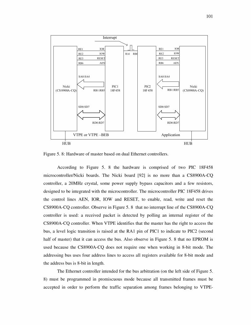
101
Nicki
(CS8900A-CQ)
Nicki
(CS8900A-CQ)
PIC1
18F458
PIC2
18F458
HUB HUB
Interrupt
RESET
IOR
IOW
AEN
RB0RA1
VTPE or VTPE -BEB Application
RESET
IOR
IOW
AEN
RE3
RE1
RE2
RB6
RE3
RE1
RE2
RB6
SA0:SA4
RB1:RB5
SA0:SA4
RB1:RB5
SD0:SD7
RD0:RD7
SD0:SD7
RD0:RD7
Figure 5. 8: Hardware of master based on dual Ethernet controllers.
According to Figure 5. 8 the hardware is comprised of two PIC 18F458
microcontroller/Nicki boards. The Nicki board [92] is no more than a CS8900A-CQ
controller, a 20MHz crystal, some power supply bypass capacitors and a few resistors,
designed to be integrated with the microcontroller. The microcontroller PIC 18F458 drives
the control lines AEN, IOR, IOW and RESET, to enable, read, write and reset the
CS8900A-CQ controller. Observe in Figure 5. 8 that no interrupt line of the CS8900A-CQ
controller is used: a received packet is detected by polling an internal register of the
CS8900A-CQ controller. When VTPE identifies that the master has the right to access the
bus, a level logic transition is raised at the RA1 pin of PIC1 to indicate to PIC2 (second
half of master) that it can access the bus. Also observe in Figure 5. 8 that no EPROM is
used because the CS8900A-CQ does not require one when working in 8-bit mode. The
addressing bus uses four address lines to access all registers available for 8-bit mode and
the address bus is 8-bit in length.
The Ethernet controller intended for the bus arbitration (on the left side of Figure 5.
8) must be programmed in promiscuous mode because all transmitted frames must be
accepted in order to perform the traffic separation among frames belonging to VTPE-
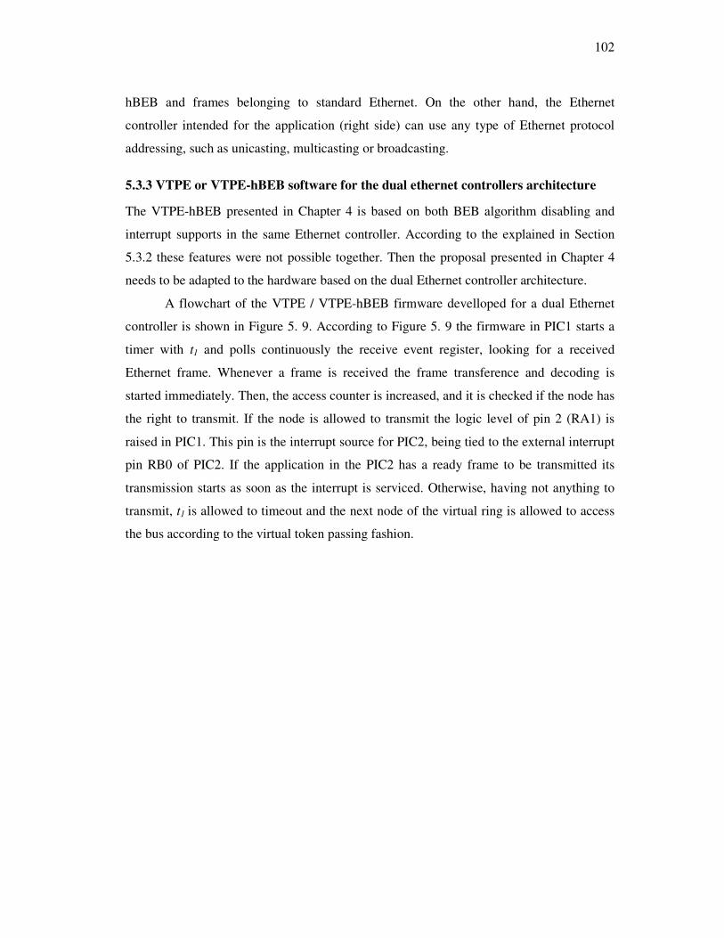
102
hBEB and frames belonging to standard Ethernet. On the other hand, the Ethernet
controller intended for the application (right side) can use any type of Ethernet protocol
addressing, such as unicasting, multicasting or broadcasting.
5.3.3 VTPE or VTPE-hBEB software for the dual ethernet controllers architecture
The VTPE-hBEB presented in Chapter 4 is based on both BEB algorithm disabling and
interrupt supports in the same Ethernet controller. According to the explained in Section
5.3.2 these features were not possible together. Then the proposal presented in Chapter 4
needs to be adapted to the hardware based on the dual Ethernet controller architecture.
A flowchart of the VTPE / VTPE-hBEB firmware develloped for a dual Ethernet
controller is shown in Figure 5. 9. According to Figure 5. 9 the firmware in PIC1 starts a
timer with t1 and polls continuously the receive event register, looking for a received
Ethernet frame. Whenever a frame is received the frame transference and decoding is
started immediately. Then, the access counter is increased, and it is checked if the node has
the right to transmit. If the node is allowed to transmit the logic level of pin 2 (RA1) is
raised in PIC1. This pin is the interrupt source for PIC2, being tied to the external interrupt
pin RB0 of PIC2. If the application in the PIC2 has a ready frame to be transmitted its
transmission starts as soon as the interrupt is serviced. Otherwise, having not anything to
transmit, t1 is allowed to timeout and the next node of the virtual ring is allowed to access
the bus according to the virtual token passing fashion.
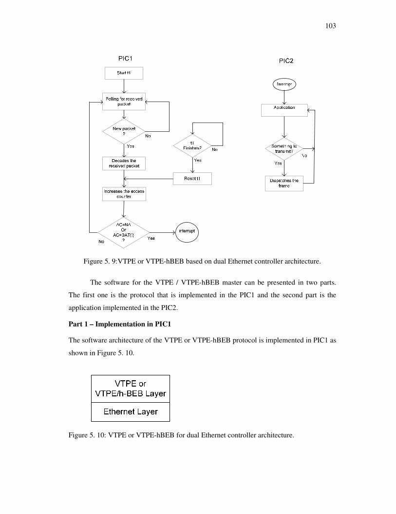
103
Figure 5. 9:VTPE or VTPE-hBEB based on dual Ethernet controller architecture.
The software for the VTPE / VTPE-hBEB master can be presented in two parts.
The first one is the protocol that is implemented in the PIC1 and the second part is the
application implemented in the PIC2.
Part 1 – Implementation in PIC1
The software architecture of the VTPE or VTPE-hBEB protocol is implemented in PIC1 as
shown in Figure 5. 10.
Figure 5. 10: VTPE or VTPE-hBEB for dual Ethernet controller architecture.

104
As shown in Figure 5. 10 the software implemented in PIC1 doesn’t include the
application because it is executed in the PIC2. Then the software architecture is comprised
only of the Ethernet Layer and the VTPE or VTPE-hBEB Layer. Remember that VTPE
differs from VTPE-hBEB because VTPE-hBEB requires the BEB algorithm disabling to
allow traffic separation in order to work in unconstrained environment. The Ethernet Layer
and the VTPE or VTPE-hBEB Layer are presented bellow.
The Ethernet Layer
The Ethernet Layer is implemented with the firmware included in the cs8900.c
source file. The cs8900.c source file has a set of functions to put the CS8900A-CQ ready to
receive and transmit frames.
Table 5. 3 summarises the set of functions for the CS8900A-CQ initialisation and
to write data into and read data from the controller.
Module/
Dependence
Function Purpose
void init_CS8900AC()
Sets all parameters required before the
CS8900A-CQ becomes operational, such
as data bus width, physical address, types
of interrupts that may be serviced, size of
the Receive Buffer Ring, types of packets
that may be received.
void PPRead()
Reads data from a Packet Page of the
registers of the CS8900A-CQ controller.
void PPWrite()
Writes data to a Packet Page of the
registers of the CS8900A-CQ Ethernet
controller.
cs8900.c
void RPP(int16 ppoffset)
Reads data from the Packet Page
specified by the offset in the argument of
the function.
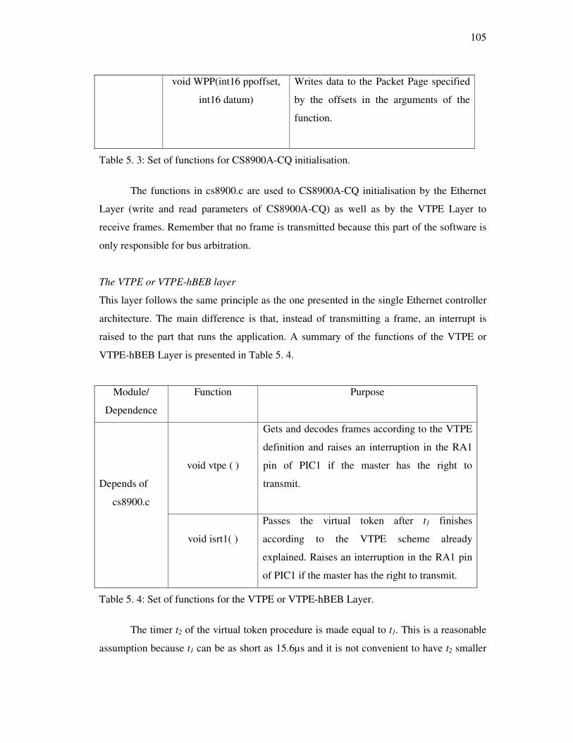
105
void WPP(int16 ppoffset,
int16 datum)
Writes data to the Packet Page specified
by the offsets in the arguments of the
function.
Table 5. 3: Set of functions for CS8900A-CQ initialisation.
The functions in cs8900.c are used to CS8900A-CQ initialisation by the Ethernet
Layer (write and read parameters of CS8900A-CQ) as well as by the VTPE Layer to
receive frames. Remember that no frame is transmitted because this part of the software is
only responsible for bus arbitration.
The VTPE or VTPE-hBEB layer
This layer follows the same principle as the one presented in the single Ethernet controller
architecture. The main difference is that, instead of transmitting a frame, an interrupt is
raised to the part that runs the application. A summary of the functions of the VTPE or
VTPE-hBEB Layer is presented in Table 5. 4.
Module/
Dependence
Function Purpose
void vtpe ( )
Gets and decodes frames according to the VTPE
definition and raises an interruption in the RA1
pin of PIC1 if the master has the right to
transmit.
Depends of
cs8900.c
void isrt1( )
Passes the virtual token after t1 finishes
according to the VTPE scheme already
explained. Raises an interruption in the RA1 pin
of PIC1 if the master has the right to transmit.
Table 5. 4: Set of functions for the VTPE or VTPE-hBEB Layer.
The timer t2 of the virtual token procedure is made equal to t1. This is a reasonable
assumption because t1 can be as short as 15.6µs and it is not convenient to have t2 smaller

106
than 15.6µs. This is because in this hardware it will increase unnecessarily the overhead in
the application. The application must be compatible with the processing capacity of the
microcontroller.
Chapter 6 discusses the timing behavior of implementations based on single and
dual Ethernet controllers as well.
A summary of the software that must be programmed in the Part 1 of the master is
as follows:
#include <18F458.h>//CCS include file for PIC 18F458
#include <vtpe.h> //Some CCS and VTPE header definitions
#include <cs8900a.h> //CS8900A-CQ pin and registers
//definitions
#include <cs890a.c> // Include the Ethernet Layer here
//according to CCS compiler ruler
#include <vtpe.c> //Include the VTPE Layer here
according //to CCS compiler ruler
// Main entry point
{
//Some specific microcontroller setups such as port
//direction, watch dog, timers, etc
void init_CS8900AC();//Initialise the CS890A-CQ
// Enter into infinite loop
While(1)
{
void vtpe (); //polling for receiving frame, decoding of
//received frame according to the VTPE procedure and
//signalise with RA1=1 when the master can access the
bus.
}
Part 2 – Implementation in PIC2
The software architecture for the second part of VTPE or VTPE-hBEB implementation
based on the dual Ethernet controller architecture is shown in Figure 5. 11
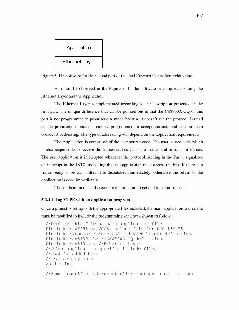
107
Figure 5. 11: Software for the second part of the dual Ethernet Controller architecture.
As it can be observed in the Figure 5. 11 the software is comprised of only the
Ethernet Layer and the Application.
The Ethernet Layer is implemented according to the description presented in the
first part. The unique difference that can be pointed out is that the CS8900A-CQ of this
part is not programmed in promiscuous mode because it doesn’t run the protocol. Instead
of the promiscuous mode it can be programmed to accept unicast, multicast or even
broadcast addressing. The type of addressing will depend on the application requirements.
The Application is comprised of the user source code. The user source code which
is also responsible to receive the frames addressed to the master and to transmit frames.
The user application is interrupted whenever the protocol running in the Part 1 signalises
an interrupt in the INT0, indicating that the application must access the bus. If there is a
frame ready to be transmitted it is dispatched immediately, otherwise the return to the
application is done immediately.
The application must also contain the function to get and transmit frames.
5.3.4 Using VTPE with an application program
Once a project is set up with the appropriate files included, the main application source file
must be modified to include the programming sentences shown as follow.
//Declare this file as main application file
#include <18F458.h>//CCS include file for PIC 18F458
#include <vtpe.h> //Some CCS and VTPE header definitions
#include <cs8900a.h> //CS8900A-CQ definitions
#include <cs890a.c> //Ethernet Layer
//Other application specific include files
//must be added here
// Main entry point
void main()
{
//Some specific microcontroller setups such as port
108
//direction, watch dog, timers, etc
init_CS8900AC();//Initialise the CS890A-CQ
// Perform application specific initialization
// Set up to external interrupt // Enter into infinite loop
While(1)
{
get_frame ();//Looks for received frame
//The user application code must be here
//The application produces and loads a VTPE frame.
//When the frame is loaded flag1 is set to 1
flag1=1;
While(flag1); //wait for VTPE
}
5.4 Implementation based on an IP core
This is a work in progress approach. It consists in embedding the VTPE and
Ethernet protocols in a single-chip. The main advantage of this solution is to run the
VTPE and Ethernet protocols simultaneously. In this proposal the VTPE arbitrates the bus
during the frame transmission and the inter-frame gap (IFG), so no extra arbitration time is
wasted. Consequently, the saved time is reverted in the efficiency throughput. This
improvement is possible due to the low VTPE processing requirements, to the processing
power of FPGAs and to the use of the transceiver, which makes possible to run VTPE
during the frame transmission. Then this new proposal will permit to reach,
deterministically, the theoretical limits of Ethernet 10/100Mbps efficiency throughput
(54.6% for minimal size frame and 97.5% for maximum size frame) that is found when
there is a single transmitting node in the bus. On the other hand, it should be remembered
that, in a shared Ethernet segment with more than one node, these throughput values are
unreachable due to the collisions and the probabilistic resolution algorithm (back-off
algorithm). This proposal was presented in [81] and is summarized as follows. A
simplified block diagram of the VTPE IP core is shown in Figure 5. 12.

109
Microcontroller or Processor
Memory
Data
Bus
Address
Bus
Control
Bus
VTPE
Frame Decoder
VTPE
Frame Generator
AC and NA
Checker
Receiver Control Block Transmission Control Block
Ethernet Transceiver
Receive
Signals
Transmit
Signals
t1 timer
t2 timer
t1 control t1 timeout
t2 control t2 timeout
Shared Ethernet Segment
Figure 5. 12:VTPE IP core block diagram
In the VTPE IP core proposal a node is composed of an Ethernet transceiver and its
accessory parts (magnetic transformers and RJ45 connector), a FPGA where the VTPE-
MAC firmware is implemented and a processor/microcontroller where the application
runs. It is focused in the VTPE IP core, so the Ethernet transceiver and the
microcontroller/processor aren’t presented.
The Receive Control Block controls the frame’s reception from the Ethernet
transceiver and delivers the received frame to the VTPE Frame Decoder and signalises to
the AC Counter and NA=AC Checker that a frame was received.

110
The VTPE frame decoder checks the Source Address to actualise the node’s active
table, the Data/Type field, and the data field. If there is relevant data (VTPE messages) it
delivers them to the memory, otherwise it discards the frame.
The AC and NA Checker block increments the AC and compares its value with NA
in accordance to the classic VTPE proposal or with some value in the Bandwidth
Allocation Table (BAT) in accordance to the improved VTPE proposal. It sets a flag to “1”
if AC=NA or AC=BAT(i), otherwise it sets a flag to “0” if AC ≠ NA or AC≠BAT(i).
The Transmission Control Block gets a frame to be transmitted from the VTPE
Frame Generator, controls the t1 and t2 timers, and controls the frame transmission.
The VTPE Frame Generator gets data from the Memory (VTPE messages),
generates the CRC, adds padding bits to complete the 46 minimum bytes, if necessary, and
encapsulates all this data in the Ethernet frame and delivers it to the Transmission Control
Block so that it can be transmitted to the bus.
The memory consists of two memory blocks in ring format: The Received Data
Ring and the Transmit Data Ring. Two local DMA (Direct Memory Access Controller)
channels, not shown in Figure 5. 12, are used to manage received data and to manage the
transmission of data. The first one, during a frame reception, stores the received data from
the VTPE Frame Decoder into the Received Data Ring and, during a frame transmission,
transfers data from the Transmit Data Ring to the VTPE Frame Generator to be transmitted
to the controller. The second DMA channel is used to transfer data between memory
(Received Data Ring or Transmit Data Ring) and the host processor.
5.5 Conclusions
This chapter presents two implementation carried out during the VTPE and VTPE-hBEB
development. The first implementation is based on a single Ethernet controller and it is
aimed for VTPE because the used Ethernet controller doesn’t support BEB algorithm
disabling. A similar implementation can be suitable for VTPE-hBEB protocol if the
Ethernet controller is changed to one that supports the BEB algorithm disabling. The
implementation based on a single Ethernet controller is simpler and cheaper than the one
based on a dual controller.
The implementation based on dual Ethernet controller architecture uses Ethernet
controllers that support BEB disabling, then it is suitable to implement the VTPE-hBEB
111
protocol. The dual Ethernet controller architecture is also suitable to implement VTPE
because VTPE can also work with the BEB algorithm disabled.
The VTPE-hBEB protocol avoids the collision of frames coming from masters
(hBEB algorithm) and the hBEB algorithm solves the collisions that can occur among
standard Ethernet stations and VTPE-hBEB masters. This procedure allows separating the
real-time traffic from the non real-time.
The implementation based on a dual Ethernet has the advantages to solve the
interrupt problem of CS8900A-CQ when it works in 8-bit mode, to increase the processing
power, because it uses two microcontrollers, and to reduce the processing overhead in the
microcontroller (PIC2) because the interruption is raised on only when the master has the
right to access the bus. However this implementation has a disadvantage, that is being
more expensive than the one based on a single Ethernet controller because it uses a couple
of microcontroller/Ethernet-controller per node and requires more cabling.
The implementation based on a dual Ethernet controller architecture doesn’t
invalidate the implementation of VTPE or VTPE-hBEB protocols because, conceptually, it
is equivalent to a node with more processing power with an Ethernet controller able to
support the BEB algorithm disabling and interrupt.
The implementation based on IP core is not finished yet but it seems a very
promising proposal. This implementation will permit deterministically to reach the
maximum bus utilization that can be achieved on a shared Ethernet segment without
collisions.

112
113
Chapter 6
Timing Behavior and Validation of VTPE and
VTPE-hBEB
6.1 Introduction
This chapter discusses the arbitration time of VTPE and VTPE-hBEB and the timing
behavior of these protocols regarding to the transmission of a time sensitive data flow. The
discussion is according to the implementations carried out in the demonstrators discussed
in the Chapter 5.
In order to evaluate the timing behavior of VTPE and VTPE-hBEB, the medium
arbitration time, i.e., the required time to run these protocols was determined.
Two methods are envisaged to determine the time to execute the VTPE and VTPE-
hBEB protocols:
• The first method consists in starting an internal timer of the microcontroller to
count the number of machine cycles between an interrupt of the Ethernet controller
and the instant when the master can access the bus and dispatch the frame. The
number of instruction cycles to start and to stop must be discounted from the
obtained number of machine cycles. The total of machine cycles is then converted
to time using the time taken to execute a machine cycle in the specific hardware
architecture. The measured time is exactly the lower bound for t1.
• The second method consists in totalising the number of machine cycles using the
assembly list provided by the compiler and, after, in converting the total number of
114
machine cycles to time using the time taken to execute a machine cycle in the
specific hardware architecture.
Both methods have shown to be adequate and have produced similar results.
To validate VTPE and VTPE-hBEB, the transmission of a time sensitive data flow
was used. The choice was the MIDI protocol which is a de facto standard for the
interconnection of musical instruments. MIDI data flows use an exclusive communication
channel and time is implicitly encoded in the transmission instant. The MIDI hardware
uses a RS-232 like character oriented transmission with a baud rate of 31.25kbps, thus it is
suitable for validation of VTPE and VTPE-hBEB protocols because it is not too heavy in
bandwidth requirements and it is also compatible with the processing capacity of the
microcontrollers used in the demonstrators.
The remaining of this chapter is as follows: Section 6.2 presents the timing
behavior of VTPE in the implementation based on single controller. Section 6.3 presents
the timing behavior of VTPE and VTPE-hBEB implementations based on the dual
controller architecture. Section 6.4 presents an overview of the MIDI protocol, describes
the application setup for the validation of the protocols, and discusses some results. Section
6.5 presents the conclusions.
6.2 Timing behavior of VTPE in the implementation based on single
controller
The tests carried out in the implementation based on a single Ethernet controller were
aimed to show the system working according to the virtual token-passing procedure and to
determine the minimum t1 value to run the VTPE, as well as to determine the bus
utilization. For this particular test it was defined that:
• Each master must transmit a predefined Ethernet frame;
• The Ethernet frame carries a VTPE frame inside the data field. The VTPE frame
(header plus data) varies from the smallest Ethernet data field (46 bytes of data) to
1242 bytes. The limit of 1242 bytes is due to the built in RAM memory of the
microcontroller used to store the frame and the other variables regarding the VTPE
implementation;

115
• All masters must receive each transmitted frame and transfer it to the PIC memory.
The bus utilisation will be calculated using the t1 value and the time to transmit the
correspondent Ethernet frame. The bus utilisation is calculated according to the following
equation (6.1).
))/(1( 11 fdtttU +−= (6.1)
The t1 and tfd parameters are as already defined. The tfd includes the time to transmit the
Ethernet frame including the preamble bytes and the start frame delimiter.
Table 6.1 summarises the experimental results of the tests carried out.
Data
(Bytes)
Frame Length including preamble
(Bytes) and Start Frame Delimiter
tfdmax
(µS)
t1 (µS)
Network Utilisation
U=(1-t1/(t1+tfd))
46 72 57.6 297.60 16.2
138 164 131.2 693.60 15.9
276 302 241.6 1288.8 15.8
414 440 352.0 1883.2 15.8
552 578 462.4 2476.8 15.7
690 716 572.8 3071.2 15.7
828 854 683.2 3665.6 15.7
966 992 793.6 4260.0 15.7
1104 1130 904.0 4854.4 15.7
1242 1268 1014.4 5448.0 15.7
Table 6.1: t1 and bus utilisation in the implementation based on a single Ethernet controller.
The data of
Table 6.1 are plotted in Figure 6. 1.

116
t1 x Utilisation
15,6
15,7
15,8
15,9
16
16,1
16,2
16,3
0 2 4 6 8 10 12
t1 (ms)
Uti
lisati
on
(%
)
Series1
Figure 6. 1: t1 (µs) x bus utilisation (%).
Table 6.1 and Figure 6. 1 show that the obtained utilisation is quite modest and
decreases when the Ethernet frame length increases. The modest network utilisation is due
to the low processing power of the microcontrollers and to the overhead imposed to the
nodes in order to accept all transmitted frames and to do some processing on each frame.
In order to minimise the impact of the processing overhead in the small processing power
processors a solution was foreseen in the classic proposal as presented in the Chapter 3.
This solution consists in avoiding that these masters transmit long frames and receive long
frames as well. To implement this solution, it was provided the NI,GI field in the VTPE
header. This field enables the creation of sub networks to which can be connected small
processing power processors. However, in the implementation based on a single Ethernet
controller presented in the Chapter 5, the best utilisation is bounded to 16.2 %.
6.3 Timing behavior of VTPE in the implementation based on the dual
controller architecture
To determine the arbitration time of VTPE or VTPE-hBEB in the dual Ethernet
controller architecture, the elapsed time since PIC1 senses a received frame until a new
frame starts being transmitted on the bus by PIC2, must be determined. The time portions
involved with the implementation based on the dual Ethernet controller were presented in
Chapter 4 and now repeated for clarity reason. The time portions involved in the arbitration
time are:
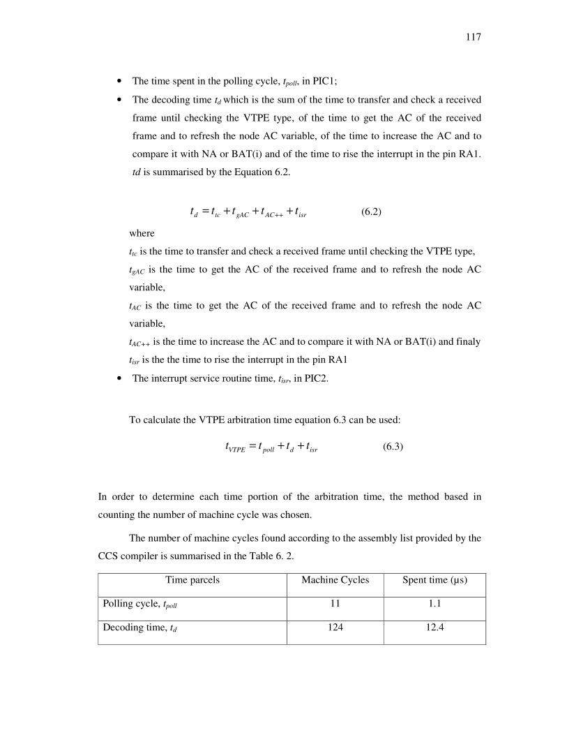
117
• The time spent in the polling cycle, tpoll, in PIC1;
• The decoding time td which is the sum of the time to transfer and check a received
frame until checking the VTPE type, of the time to get the AC of the received
frame and to refresh the node AC variable, of the time to increase the AC and to
compare it with NA or BAT(i) and of the time to rise the interrupt in the pin RA1.
td is summarised by the Equation 6.2.
isrACgACtcd ttttt +++= ++ (6.2)
where
ttc is the time to transfer and check a received frame until checking the VTPE type,
tgAC is the time to get the AC of the received frame and to refresh the node AC
variable,
tAC is the time to get the AC of the received frame and to refresh the node AC
variable,
tAC++ is the time to increase the AC and to compare it with NA or BAT(i) and finaly
tisr is the the time to rise the interrupt in the pin RA1
• The interrupt service routine time, tisr, in PIC2.
To calculate the VTPE arbitration time equation 6.3 can be used:
isrdpollVTPE tttt ++= (6.3)
In order to determine each time portion of the arbitration time, the method based in
counting the number of machine cycle was chosen.
The number of machine cycles found according to the assembly list provided by the
CCS compiler is summarised in the Table 6. 2.
Time parcels Machine Cycles Spent time (µs)
Polling cycle, tpoll 11 1.1
Decoding time, td 124 12.4

118
Interrupt service routine time, tisr (PIC2) 21 2.1
VTPE arbitration time tVTPE 156 15.6
Table 6. 2: Arbitration time on the dual Ethernet controller architecture.
Observe in Table 6. 2 that the number of machine cycles is converted to time taking
into account 0.1µs (100ns) per machine cycle. 0.1µs is the machine cycle time for the PIC
18F458 at 40 MHz.
As shown in Table 6. 2, VTPE requires at least 15.6µs to arbitrate the bus when
implemented in the dual Ethernet controller architecture reported in the Chapter 5. Then t1
must be equal or greater than 15.6µs and should be chosen taking into account the
processing capacity of the microcontroller that hosts the application. A small value of t1,
near 15.6µs, can cause unnecessary overhead in the application.
Remember that, according to the dual Ethernet controller architecture, the VTPE
and the application run in different microcontrollers. Then the application is interrupted
only when the node has the right to transmit. Then, if the application has a ready frame to
transmit whenever it is interrupted, VTPE will be able to transmit a frame with an inter-
frame gap of 15.6µs. If the application in PIC2 is not able to dispatch a frame with 15.6µs
of inter-frame gap the protocol’s velocity is not reduced because, when the master can
access the bus but it is not ready to transmit, the token will be passed after t2 expires. Also
remember that, according to the VTPE definition, t2 is smaller then t1 but, due to the small
value of t1, it can be done equal to t1. This is a reasonable assumption because t1 can be as
short as 15.6µs and it is not convenient to have t2 smaller than 15.6µs because this
increases unnecessarily the overhead in the application.
A possible transmission scenario in VTPE when implemented in the dual Ethernet
controller architecture is depicted in Figure 6. 2.
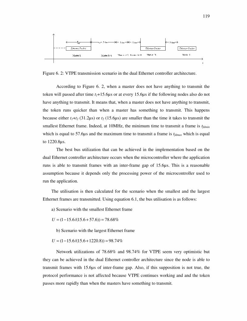
119
Figure 6. 2: VTPE transmission scenario in the dual Ethernet controller architecture.
According to Figure 6. 2, when a master does not have anything to transmit the
token will passed after time t1+15.6µs or at every 15.6µs if the following nodes also do not
have anything to transmit. It means that, when a master does not have anything to transmit,
the token runs quicker than when a master has something to transmit. This happens
because either t1+t2 (31.2µs) or t2 (15.6µs) are smaller than the time it takes to transmit the
smallest Ethernet frame. Indeed, at 10MHz, the minimum time to transmit a frame is tfdmin
which is equal to 57.6µs and the maximum time to transmit a frame is tfdmax which is equal
to 1220.8µs.
The best bus utilization that can be achieved in the implementation based on the
dual Ethernet controller architecture occurs when the microcontroller where the application
runs is able to transmit frames with an inter-frame gap of 15.6µs. This is a reasonable
assumption because it depends only the processing power of the microcontroller used to
run the application.
The utilisation is then calculated for the scenario when the smallest and the largest
Ethernet frames are transmitted. Using equation 6.1, the bus utilisation is as follows:
a) Scenario with the smallest Ethernet frame
%68.78))6.576.15/(6.151( =+−=U
b) Scenario with the largest Ethernet frame
%74.98))8.12206.15/(6.151( =+−=U
Network utilizations of 78.68% and 98.74% for VTPE seem very optimistic but
they can be achieved in the dual Ethernet controller architecture since the node is able to
transmit frames with 15.6µs of inter-frame gap. Also, if this supposition is not true, the
protocol performance is not affected because VTPE continues working and and the token
passes more rapidly than when the masters have something to transmit.

120
For the VTPE-hBEB protocol, t1 must be chosen according to the time required by
the hBEB algorithm to win the collisions that can occur due to the nature of the
unconstrained environment. As presented in the Section 4.2.3 of Chapter 4, if no frame is
discarded, the maximum time that a VTPE-hBEB station holding the token waits to
transfer a real-time message is given by the equation (4.1):
fdcolhBEB tIFGtT ++= 4.1
where tcol is the worst-case delay to start transferring a message (0.960 ms as shown in
Table 4.1), IFG is the Inter Frame Gap (12 byte-times) and tfd is the time to transfer a
frame from the VTPE-hBEB station, which is the maximum message length.
The equation 4.1 can be adapted to include the arbitration time of the
implementation based on a dual Ethernet controller architecture. Then, equation 4.1 can be
rewritten as shown bellow:
ustIFGtt fdcol 6.151 +++=
6.4
Remember that, according to the hBEB algorithm (Chapter 2 Section 2.4.1), the
probabilistic timing analysis had shown that, in a heavily loaded network scenario, the
maximum access delay for 95% of the messages is smaller than 1.86ms. Secondly, and for
more realistic load scenarios (intermediate load cases), the simulation analysis shows that
the maximum access delay for 98% of the messages is always smaller than 1ms (1000µs).
Then, including the arbitration time required in the dual Ethernet controller architecture,
the access delay t1 can be bounded to 1875.6µs for a heavily loaded network scenario and
to 1015.6µs for more realistic load scenarios (intermediate load cases).
In order to guarantee that no collisions between VTPE-hBEB frames will occur, t1
must be set equal to the bound found for VTPE-hBEB as stated above. However, if the
node doesn’t have anything to transmit, the system must wait that t1 expires in order to
pass the virtual token. If the bounded for t1 is too long then the network utilisation is
reduced. A solution is to use two bounds for t1. One is uded when a VTPE-hBEB frame
contends for the medium with a standard Ethernet frame, and other, is used otherwise.
However, the current Ethernet controllers don’t support this feature. An implementation of
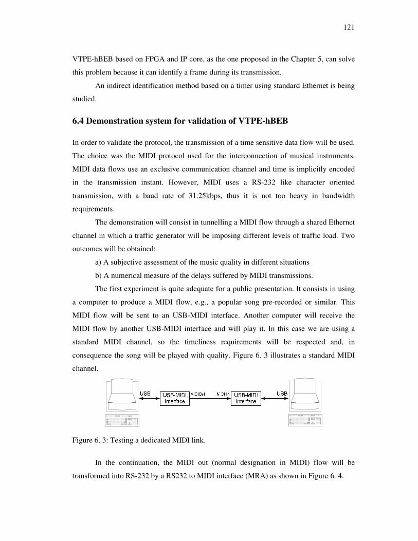
121
VTPE-hBEB based on FPGA and IP core, as the one proposed in the Chapter 5, can solve
this problem because it can identify a frame during its transmission.
An indirect identification method based on a timer using standard Ethernet is being
studied.
6.4 Demonstration system for validation of VTPE-hBEB
In order to validate the protocol, the transmission of a time sensitive data flow will be used.
The choice was the MIDI protocol used for the interconnection of musical instruments.
MIDI data flows use an exclusive communication channel and time is implicitly encoded
in the transmission instant. However, MIDI uses a RS-232 like character oriented
transmission, with a baud rate of 31.25kbps, thus it is not too heavy in bandwidth
requirements.
The demonstration will consist in tunnelling a MIDI flow through a shared Ethernet
channel in which a traffic generator will be imposing different levels of traffic load. Two
outcomes will be obtained:
a) A subjective assessment of the music quality in different situations
b) A numerical measure of the delays suffered by MIDI transmissions.
The first experiment is quite adequate for a public presentation. It consists in using
a computer to produce a MIDI flow, e.g., a popular song pre-recorded or similar. This
MIDI flow will be sent to an USB-MIDI interface. Another computer will receive the
MIDI flow by another USB-MIDI interface and will play it. In this case we are using a
standard MIDI channel, so the timeliness requirements will be respected and, in
consequence the song will be played with quality. Figure 6. 3 illustrates a standard MIDI
channel.
Figure 6. 3: Testing a dedicated MIDI link.
In the continuation, the MIDI out (normal designation in MIDI) flow will be
transformed into RS-232 by a RS232 to MIDI interface (MRA) as shown in Figure 6. 4.

122
Figure 6. 4: MIDI to RS232 level logic adaptation.
In order to insert a MIDI data flow in a VTPE-BEB system, the MRA will be
connected to the serial port of the microprocessor used in the VTPE-hBEB Master modules
(VMMs) as shown in Figure 6. 5.
Figure 6. 5: MIDI to VTPE-hBEB link.
As it is also depicted in Figure 6. 5, an application running in the VMM will pack
each MIDI character incoming from the computer (left side) into an Ethernet packet
(padding bytes will be required) and will transmit the packet at once. This operation should
be very fast in order to avoid introducing excessive delay in the MIDI flow.
The inverse operation will be done in another system similar to the VMM which
will operate just as a consumer of the information. This device will receive the Ethernet
frame, extract the character and send it to its serial port. A RS232 to MIDI electrical
adaptation is also required in order to connect the serial port to the USB-MIDI interface. A
second computer (right side) will receive the MIDI flow and play the song.
In this experiment the Ethernet channel will be undisturbed by injected traffic. If
the delays introduced are negligible there will be again a good quality output. Figure 6.6
illustrates the MIDI to VTPE-hBEB link with Ethernet traffic injection.

123
Figure 6.6: MIDI to VTPE-hBEB link with Ethernet traffic injection.
This experiment will continue by perturbing now the shared Ethernet channel with
random traffic produced by a traffic injector, in our case the Distributed Internet Traffic
Generator (D-ITG).
The D-ITG [99] traffic generator allows injecting traffic in the Ethernet shared
channel in a controlled way. The main features of D-ITG concerning timing in the traffic
generation are:
• The traffic load can be controlled by setting the length and number of frames to
send;
• It is capable to produce traffic at packet level accurately replicating appropriate
stochastic processes for both IDT (Inter Departure Time) and PS (Packet Size)
random variables (exponential, uniform, cauchy, normal, pareto,).
In order to validate the VTPE-hBEB protocol, the following experiment will use
the VTPE-hBEB middleware in two VMMs, each transmitting a MIDI traffic flow. A
consumer (or two) can be switched to receive the MIDI flow. Now, by using the VTPE-
hBEB protocol, the timeliness of the flow will, in principle, be substantially improved.
A qualitative assessment can be made by playing the MIDI traffic flows in the
consumer computer.
In order to quantify the results, an additional unit is required to measure the delay
between the MIDI traffic flow in the producing node and the received flow in the
consumer node. The measuring unit measures the end-to-end time between the start bit at
the producer and at the consumer. The measuring unit will be described in the Section
6.4.1.
In order to complement the experiment to validate the VTPE-hBEB, a PC will be
used to capture all transmitted Ethernet frames during the experiment using the Ethereal
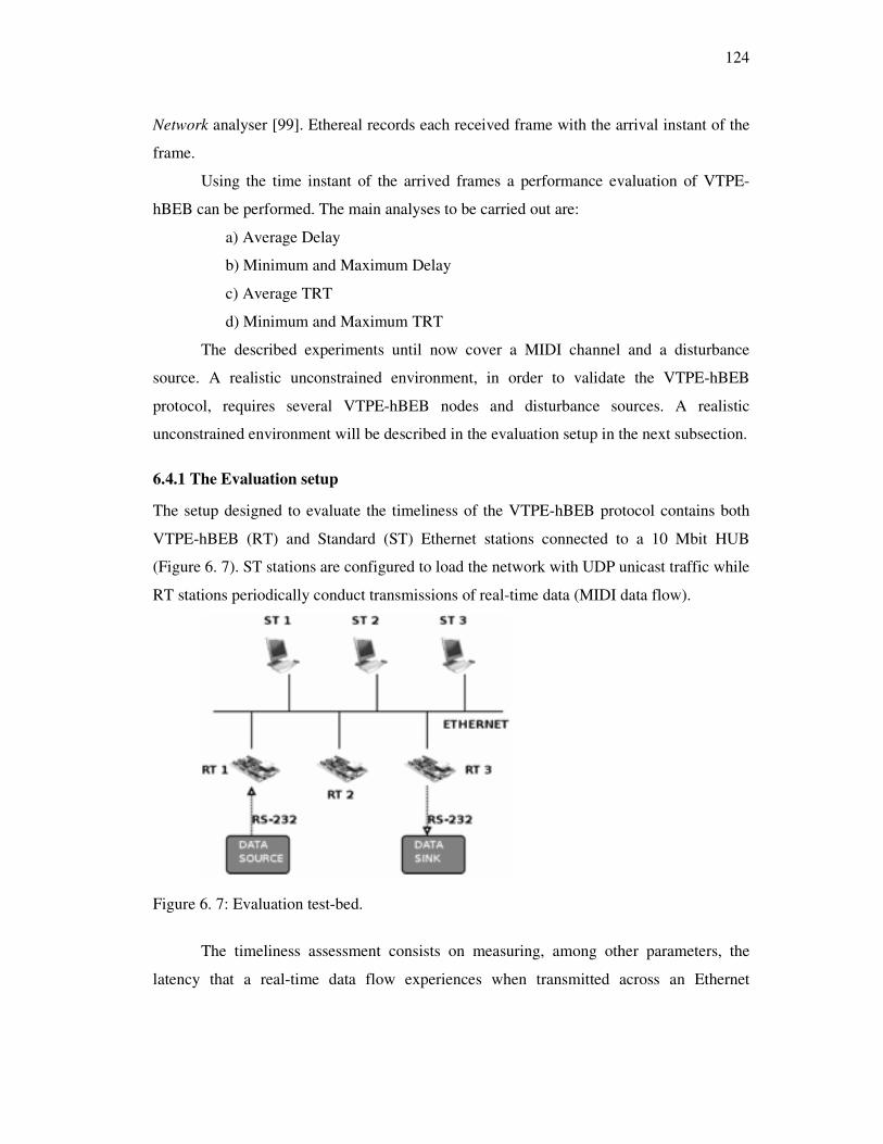
124
Network analyser [99]. Ethereal records each received frame with the arrival instant of the
frame.
Using the time instant of the arrived frames a performance evaluation of VTPE-
hBEB can be performed. The main analyses to be carried out are:
a) Average Delay
b) Minimum and Maximum Delay
c) Average TRT
d) Minimum and Maximum TRT
The described experiments until now cover a MIDI channel and a disturbance
source. A realistic unconstrained environment, in order to validate the VTPE-hBEB
protocol, requires several VTPE-hBEB nodes and disturbance sources. A realistic
unconstrained environment will be described in the evaluation setup in the next subsection.
6.4.1 The Evaluation setup
The setup designed to evaluate the timeliness of the VTPE-hBEB protocol contains both
VTPE-hBEB (RT) and Standard (ST) Ethernet stations connected to a 10 Mbit HUB
(Figure 6. 7). ST stations are configured to load the network with UDP unicast traffic while
RT stations periodically conduct transmissions of real-time data (MIDI data flow).
Figure 6. 7: Evaluation test-bed.
The timeliness assessment consists on measuring, among other parameters, the
latency that a real-time data flow experiences when transmitted across an Ethernet
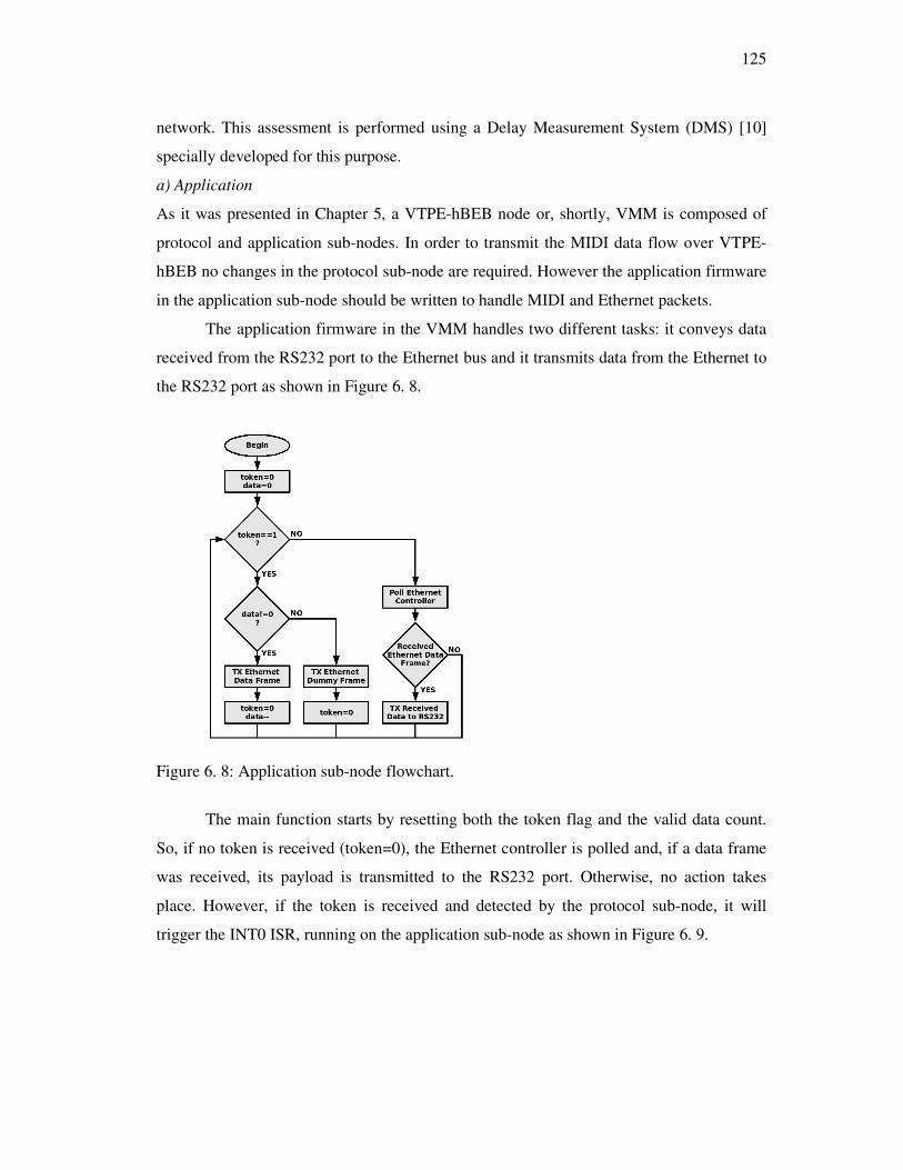
125
network. This assessment is performed using a Delay Measurement System (DMS) [10]
specially developed for this purpose.
a) Application
As it was presented in Chapter 5, a VTPE-hBEB node or, shortly, VMM is composed of
protocol and application sub-nodes. In order to transmit the MIDI data flow over VTPE-
hBEB no changes in the protocol sub-node are required. However the application firmware
in the application sub-node should be written to handle MIDI and Ethernet packets.
The application firmware in the VMM handles two different tasks: it conveys data
received from the RS232 port to the Ethernet bus and it transmits data from the Ethernet to
the RS232 port as shown in Figure 6. 8.
Figure 6. 8: Application sub-node flowchart.
The main function starts by resetting both the token flag and the valid data count.
So, if no token is received (token=0), the Ethernet controller is polled and, if a data frame
was received, its payload is transmitted to the RS232 port. Otherwise, no action takes
place. However, if the token is received and detected by the protocol sub-node, it will
trigger the INT0 ISR, running on the application sub-node as shown in Figure 6. 9.
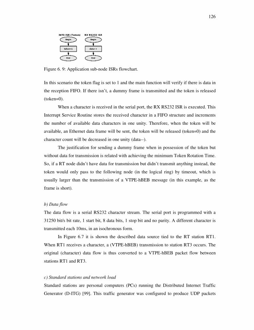
126
Figure 6. 9: Application sub-node ISRs flowchart.
In this scenario the token flag is set to 1 and the main function will verify if there is data in
the reception FIFO. If there isn’t, a dummy frame is transmitted and the token is released
(token=0).
When a character is received in the serial port, the RX RS232 ISR is executed. This
Interrupt Service Routine stores the received character in a FIFO structure and increments
the number of available data characters in one unity. Therefore, when the token will be
available, an Ethernet data frame will be sent, the token will be released (token=0) and the
character count will be decreased in one unity (data--).
The justification for sending a dummy frame when in possession of the token but
without data for transmission is related with achieving the minimum Token Rotation Time.
So, if a RT node didn’t have data for transmission but didn’t transmit anything instead, the
token would only pass to the following node (in the logical ring) by timeout, which is
usually larger than the transmission of a VTPE-hBEB message (in this example, as the
frame is short).
b) Data flow
The data flow is a serial RS232 character stream. The serial port is programmed with a
31250 bit/s bit rate, 1 start bit, 8 data bits, 1 stop bit and no parity. A different character is
transmitted each 10ms, in an isochronous form.
In Figure 6.7 it is shown the described data source tied to the RT station RT1.
When RT1 receives a character, a (VTPE-hBEB) transmission to station RT3 occurs. The
original (character) data flow is thus converted to a VTPE-hBEB packet flow between
stations RT1 and RT3.
c) Standard stations and network load
Standard stations are personal computers (PCs) running the Distributed Internet Traffic
Generator (D-ITG) [99]. This traffic generator was configured to produce UDP packets
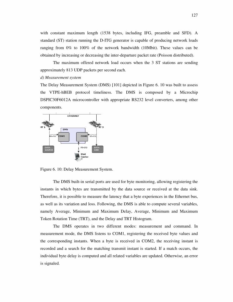
127
with constant maximum length (1538 bytes, including IFG, preamble and SFD). A
standard (ST) station running the D-ITG generator is capable of producing network loads
ranging from 0% to 100% of the network bandwidth (10Mbit). These values can be
obtained by increasing or decreasing the inter-departure packet rate (Poisson distributed).
The maximum offered network load occurs when the 3 ST stations are sending
approximately 813 UDP packets per second each.
d) Measurement system
The Delay Measurement System (DMS) [101] depicted in Figure 6. 10 was built to assess
the VTPE-hBEB protocol timeliness. The DMS is composed by a Microchip
DSPIC30F6012A microcontroller with appropriate RS232 level converters, among other
components.
Figure 6. 10: Delay Measurement System.
The DMS built-in serial ports are used for byte monitoring, allowing registering the
instants in which bytes are transmitted by the data source or received at the data sink.
Therefore, it is possible to measure the latency that a byte experiences in the Ethernet bus,
as well as its variation and loss. Following, the DMS is able to compute several variables,
namely Average, Minimum and Maximum Delay, Average, Minimum and Maximum
Token Rotation Time (TRT), and the Delay and TRT Histogram.
The DMS operates in two different modes: measurement and command. In
measurement mode, the DMS listens to COM1, registering the received byte values and
the corresponding instants. When a byte is received in COM2, the receiving instant is
recorded and a search for the matching transmit instant is started. If a match occurs, the
individual byte delay is computed and all related variables are updated. Otherwise, an error
is signaled.

128
A measurement trial ends when one of the following events occur: automatic time-
out, automatic number of bytes or manual trigger. Any of them will cause the DMS to
commute to command mode. The automatic time-out (duration of the trial) and the number
of bytes can be setup by the user. The manual trigger event is generated by switching a
knob on the DMS, and overrides any of the automatic ending mechanisms.
In command mode the DMS operates by accepting character sequences from the PC
(“commands”) and replying with status messages or with statistical information. The DMS
also allows the configuration of statistical related parameters. Both (Delay and TRT)
histograms can be customized by changing the beginning time, the number of used points
and resolution. The user is then able to change the appearance of the histogram to fit
his/her requirements.
6.5 Timing analysis
Considering a real-time data flow connected to an RT node, e.g. the RS-232 stream in the
example used the instances of the flow messages can be represented by:
Mn,i, where n is the number of the RT node and i the instance of the message.
As the external system (the RS-232 source) and the VTPE-hBEB evaluation system
are independent and thus not synchronized, the activation instant of the message Mn,i is
asynchronous relatively to the VTPE token rotation.
The connection between the external system and the RT node is point to point. If
the end of the reception at the RT node is considered the activation instant of Mn,i within
the VTPE system, then the time it takes to transmit the payload between the external
system and the RT node can be ignored.
However, after the activation, two time intervals must be taken into consideration
before Mn,i can be transmitted in the Ethernet network. These are the time required to
handle the reception of Mn,i from the external system, thr,i, and the time it takes to transfer
the payload of Mn,i to the Ethernet controller of the RT node, ttc,i.
After thr,i two situations can occur:
a) The Ethernet controller is busy transmitting a previous message Mn,i-1 from the node and
thus the loading of the message in the controller is delayed.
b) The Ethernet controller is available and Mn,i can be loaded at once.

129
In situation a), the transmission of Mn,i-1 can be considered a part of the token
rotation time. In this case the token rotation counting starts right after the start of the
transmission of Mn,i-1. The delay in a) doesn’t need to be taken into account provided that
the time to transfer Mn,i to the Ethernet controller is sufficiently low to fit within the slack
obtained by the token rotation time subtracted from the transmission time of Mn,i-1. That is:
[ ]Nttt iitRTiitc .....1,1,1, ∈∀−= −− (6.5)
Where:
N is the maximum number of messages
ttc,i is the time required to transfer the message Mn,i from the reception buffer of the
RT node to its Ethernet controller. This time can not be ignored due to the use of
low-processing power microcontrollers.
tRTi-1 is the token rotation time that occurred in the sequence of the transmission of
message Mn,i-1.
tt,i-1 is the transmission time of message Mn,i-1.
This condition can be made completely general by using the worst case concerning
the loading of the payload in the Ethernet controller, the length of the transmitted messages
and the minimum token rotation time. The general condition is then the following:
tMAXRTMINItcMAX TTT −< (6.6)
Where:
TtcMAX.= Max(ttc,i), [1.. ]i N∀ ∈ , is the maximum time it takes to transfer the payload
to the Ethernet controller.
TRTMIN .= Min(trt,i), [1.. ]i N∀ ∈ , is the minimum token rotation time.
TtMAX = Max(tt,i), [1.. ]i N∀ ∈ , is the maximum transmission time of every Ethernet
frame from the RT node.
The worst case delay concerning scenario a), till the start of transmission of
message Mn,i is then:
T tD RTwcihr,i(a)wc, += (6.7)

130
Considering now scenario b), the worst case occurs when the loading of the
Ethernet controller finishes immediately after the exhausting of the time out (named t2 in
the original VTPE protocol specification) [4], when node n had nothing to transmit in the
previous token round. That means then that the token has been just released by node n.
This situation doesn’t happen in the application example as we are forcing the RT stations
to transmit a dummy frame even when there are no RT messages.
If it is avoided to perform a fine tuning of the token rotation time (as it was done for
scenario a)), then the maximum time between the release of the token and its next
reception can be limited by the maximum token rotation time. Then, for this case, we have:
RTwcitc,ihr,iwc, T t t (b)D ++= ( 8.6 )
That is, without fine tuning of the token rotation time, one must consider D’wc,i(b)
as the worst case delay.
The maximum time that a RT station holding the token waits to transfer a real-time
message is given by [33]:
ThBEB = tcol +InterFrameGap+TtMAX
where tcol is the worst-case delay to start transferring a message (0.960 ms) due to blocking
in the network in the sequence of 15 collision rounds.
and TtMAX is the maximum time to transfer a message from the VTPE-hBEB station,
which is the maximum message length, as defined above.
After the D’ interval, Mn,i is ready to start competing for the bus and then the
ThBEB equation gives the time it takes to be transmitted. In consequence, the worst case
delay till the end of transmission for Mn,i is:
RTwcihBEB,itc,ihr,iwc, T t t t D +++= ( 9.6 )
Where thBEB,i is the time it takes to transmit the message Mn,i once the token is in
possession of the station n.
The use of low-processing power microcontrollers has also other implications in the
VTPE-hBEB protocol implementation. Recalling the VTPE protocol, after a successful
transmission of a VTPE RT message or after a time out called t2 [80], an interrupt will be
generated in every RT node in order to increment the AC counters. After this increment,
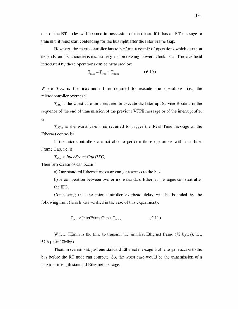
131
one of the RT nodes will become in possession of the token. If it has an RT message to
transmit, it must start contending for the bus right after the Inter Frame Gap.
However, the microcontroller has to perform a couple of operations which duration
depends on its characteristics, namely its processing power, clock, etc. The overhead
introduced by these operations can be measured by:
tRTmISRuCo T T T += ( 10.6 )
Where TuCo is the maximum time required to execute the operations, i.e., the
microcontroller overhead.
TISR is the worst case time required to execute the Interrupt Service Routine in the
sequence of the end of transmission of the previous VTPE message or of the interrupt after
t2.
TtRTm is the worst case time required to trigger the Real Time message at the
Ethernet controller.
If the microcontrollers are not able to perform those operations within an Inter
Frame Gap, i.e. if:
TuCo > InterFrameGap (IFG)
Then two scenarios can occur:
a) One standard Ethernet message can gain access to the bus.
b) A competition between two or more standard Ethernet messages can start after
the IFG.
Considering that the microcontroller overhead delay will be bounded by the
following limit (which was verified in the case of this experiment):
EminuCo T GapInterFrame T +< ( 11.6 )
Where TEmin is the time to transmit the smallest Ethernet frame (72 bytes), i.e.,
57.6 µs at 10Mbps.
Then, in scenario a), just one standard Ethernet message is able to gain access to the
bus before the RT node can compete. So, the worst case would be the transmission of a
maximum length standard Ethernet message.

132
However, in scenario b), a worst situation can occur. It consists in the end of a
contention process followed by the start of a transmission of a standard Ethernet message
immediately before the end of the overhead interval. So, scenario b) leads to the worst case
situation arising from these microcontroller non-idealities. The maximum delay, maximum
overhead time, is then:
EmaxuCoMAXoMAX T T T += ( 12.6 )
Where TuCoMAX is the maximum microcontroller overhead handling the interrupt.
TEmax is the time to transmit the largest Ethernet message (1526 bytes), i.e., 1220.8
µs at 10Mbps.
This delay must be added to the worst case delay identified in the ThBEB equation, giving
origin to a corrected value for the non-ideal case of small processing power
microcontrollers:
hBEBoMAXhBEB T T T += ( 6.13 )
We can now derive the maximum delay that suffers, in a real VTPE-hBEB system,
the Mn,i instance of an external RT flow, considering the asynchrony between the external
system and the VTPE-hBEB evaluation system and the non-idealities of the RT nodes. It
is:
RTwcihBEB,oMAXitc,ihr,iwc, T t T t t D ++++= ( 14.6 )
This is the value that must be verified experimentally.
6.6 Results
This section presents a preliminary evaluation of the VTPE-hBEB practical
implementation. A test-bed similar to the arrangement shown in Figure 6.7 was used
altogether with the Delay Measurement System shown in Figure 6.10. All trials were
conducted using the following settings:
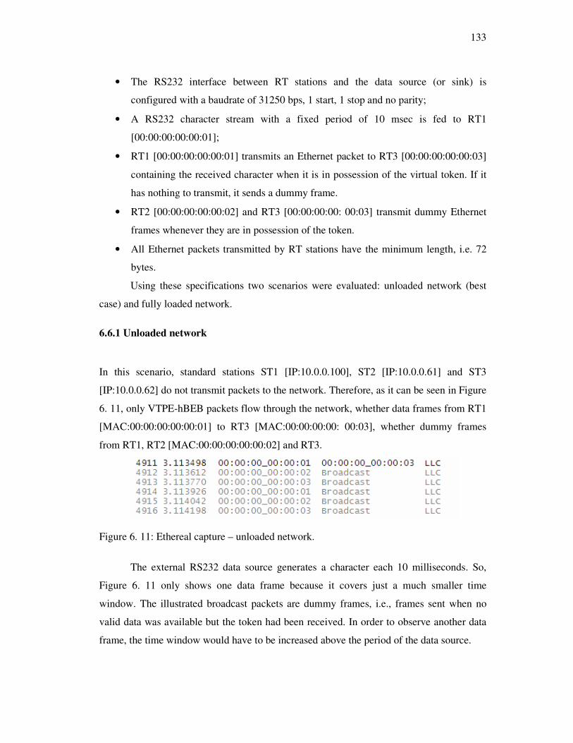
133
• The RS232 interface between RT stations and the data source (or sink) is
configured with a baudrate of 31250 bps, 1 start, 1 stop and no parity;
• A RS232 character stream with a fixed period of 10 msec is fed to RT1
[00:00:00:00:00:01];
• RT1 [00:00:00:00:00:01] transmits an Ethernet packet to RT3 [00:00:00:00:00:03]
containing the received character when it is in possession of the virtual token. If it
has nothing to transmit, it sends a dummy frame.
• RT2 [00:00:00:00:00:02] and RT3 [00:00:00:00: 00:03] transmit dummy Ethernet
frames whenever they are in possession of the token.
• All Ethernet packets transmitted by RT stations have the minimum length, i.e. 72
bytes.
Using these specifications two scenarios were evaluated: unloaded network (best
case) and fully loaded network.
6.6.1 Unloaded network
In this scenario, standard stations ST1 [IP:10.0.0.100], ST2 [IP:10.0.0.61] and ST3
[IP:10.0.0.62] do not transmit packets to the network. Therefore, as it can be seen in Figure
6. 11, only VTPE-hBEB packets flow through the network, whether data frames from RT1
[MAC:00:00:00:00:00:01] to RT3 [MAC:00:00:00:00: 00:03], whether dummy frames
from RT1, RT2 [MAC:00:00:00:00:00:02] and RT3.
Figure 6. 11: Ethereal capture – unloaded network.
The external RS232 data source generates a character each 10 milliseconds. So,
Figure 6. 11 only shows one data frame because it covers just a much smaller time
window. The illustrated broadcast packets are dummy frames, i.e., frames sent when no
valid data was available but the token had been received. In order to observe another data
frame, the time window would have to be increased above the period of the data source.

134
Figure 6.12 shows the delay distribution for an unloaded Ethernet network and
Figure 6.13 shows the TRT histogram for the same scenario. Delays are spread between 430
µs and 930 µs while the token rotation time is almost always in the range of 420 µs to 460
µs.
Figure 6.12: Delay histogram - unloaded network.
Figure 6.13: TRT histogram - unloaded network.
Table 6. 3 resumes the statistical results obtained for the Delay and Token Rotation
Time experienced on an unloaded Ethernet network.
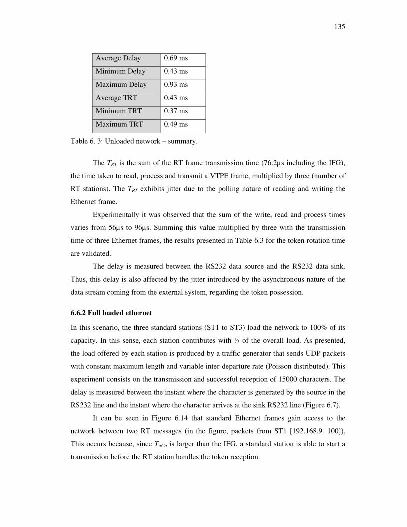
135
Average Delay 0.69 ms
Minimum Delay 0.43 ms
Maximum Delay 0.93 ms
Average TRT 0.43 ms
Minimum TRT 0.37 ms
Maximum TRT 0.49 ms
Table 6. 3: Unloaded network – summary.
The TRT is the sum of the RT frame transmission time (76.2µs including the IFG),
the time taken to read, process and transmit a VTPE frame, multiplied by three (number of
RT stations). The TRT exhibits jitter due to the polling nature of reading and writing the
Ethernet frame.
Experimentally it was observed that the sum of the write, read and process times
varies from 56µs to 96µs. Summing this value multiplied by three with the transmission
time of three Ethernet frames, the results presented in Table 6.3 for the token rotation time
are validated.
The delay is measured between the RS232 data source and the RS232 data sink.
Thus, this delay is also affected by the jitter introduced by the asynchronous nature of the
data stream coming from the external system, regarding the token possession.
6.6.2 Full loaded ethernet
In this scenario, the three standard stations (ST1 to ST3) load the network to 100% of its
capacity. In this sense, each station contributes with ⅓ of the overall load. As presented,
the load offered by each station is produced by a traffic generator that sends UDP packets
with constant maximum length and variable inter-departure rate (Poisson distributed). This
experiment consists on the transmission and successful reception of 15000 characters. The
delay is measured between the instant where the character is generated by the source in the
RS232 line and the instant where the character arrives at the sink RS232 line (Figure 6.7).
It can be seen in Figure 6.14 that standard Ethernet frames gain access to the
network between two RT messages (in the figure, packets from ST1 [192.168.9. 100]).
This occurs because, since TuCo is larger than the IFG, a standard station is able to start a
transmission before the RT station handles the token reception.

136
Figure 6.14: Ethereal capture – fully loaded network.
Figure 6.15: Delay histogram – fully loaded network.
The delay distribution shown in Figure 6.15 has become wider and ranging from
430µs to 5.77ms.
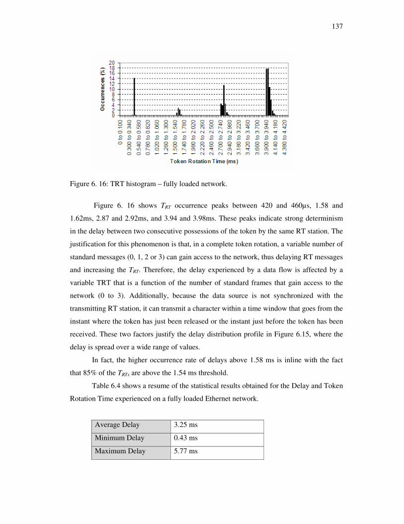
137
Figure 6. 16: TRT histogram – fully loaded network.
Figure 6. 16 shows TRT occurrence peaks between 420 and 460µs, 1.58 and
1.62ms, 2.87 and 2.92ms, and 3.94 and 3.98ms. These peaks indicate strong determinism
in the delay between two consecutive possessions of the token by the same RT station. The
justification for this phenomenon is that, in a complete token rotation, a variable number of
standard messages (0, 1, 2 or 3) can gain access to the network, thus delaying RT messages
and increasing the TRT. Therefore, the delay experienced by a data flow is affected by a
variable TRT that is a function of the number of standard frames that gain access to the
network (0 to 3). Additionally, because the data source is not synchronized with the
transmitting RT station, it can transmit a character within a time window that goes from the
instant where the token has just been released or the instant just before the token has been
received. These two factors justify the delay distribution profile in Figure 6.15, where the
delay is spread over a wide range of values.
In fact, the higher occurrence rate of delays above 1.58 ms is inline with the fact
that 85% of the TRTs are above the 1.54 ms threshold.
Table 6.4 shows a resume of the statistical results obtained for the Delay and Token
Rotation Time experienced on a fully loaded Ethernet network.
Average Delay 3.25 ms
Minimum Delay 0.43 ms
Maximum Delay 5.77 ms
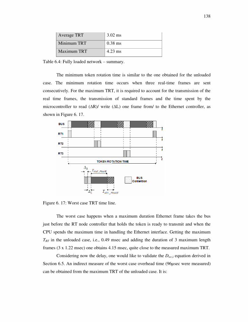
138
Average TRT 3.02 ms
Minimum TRT 0.38 ms
Maximum TRT 4.23 ms
Table 6.4: Fully loaded network – summary.
The minimum token rotation time is similar to the one obtained for the unloaded
case. The minimum rotation time occurs when three real-time frames are sent
consecutively. For the maximum TRT, it is required to account for the transmission of the
real time frames, the transmission of standard frames and the time spent by the
microcontroller to read (∆R)/ write (∆L) one frame from/ to the Ethernet controller, as
shown in Figure 6. 17.
Figure 6. 17: Worst case TRT time line.
The worst case happens when a maximum duration Ethernet frame takes the bus
just before the RT node controller that holds the token is ready to transmit and when the
CPU spends the maximum time in handling the Ethernet interface. Getting the maximum
TRT in the unloaded case, i.e., 0.49 msec and adding the duration of 3 maximum length
frames (3 x 1.22 msec) one obtains 4.15 msec, quite close to the measured maximum TRT.
Considering now the delay, one would like to validate the Dwc,i equation derived in
Section 6.5. An indirect measure of the worst case overhead time (96µsec were measured)
can be obtained from the maximum TRT of the unloaded case. It is:

139
0.105msec 3 / 0.058) . 3 (0.490 T
N)/ T . NS - (T t T T
omax
SEminRTumaxtcmaxuCoMAXomax
==
=+=
Now, decomposing the Dwc,i equation, we have:
RTwctMAXcol
EmaxuCoMAXitc,ihr,iwc,
T T GapInterFrame t
T T t t D
++++
++++=
Ignoring thr,i, which must be small as it corresponds just to a small ISR and a write in a
buffer, and InterFrameGap which is around 10µsec, we have:
tcol 5.614 D
4.230 0.058 tcol 1.221 0.105 D
wc
wc
+=
++++=
tcol represents the possible collision resolution of the hBEB process, with a worst case of
0.96 msec. It seems that, in our experiment, RT nodes were able to win the collision in one
of the first back off slots (which last 64, 128, 196, ... µsec). This is a reasonable
assumption since we are just using three stations to induce traffic load.
6.7 Conclusions
The conclusions are presented according to the implementations and the experimental
setup for VTPE-hBEB validation.
About the Implementations
The implementation of VTPE based on a single Ethernet controller has a very small
footprint. It occupies approximately 9% of the available flash memory of the
microcontroller used. This is an important result because this VTPE version is to be used in
small processing power processors. A modest network utilisation (16.2% with minimum
frame size) was obtained. However, this is can be considered a good result since a small
processing power microcontroller is used. The utilisation decreases noticeably with the
Ethernet frame length due to the interface between the microcontroller and the Ethernet
controller which is 8 bits in length. This interface requires a significant time to transfer a
frame from the Ethernet controller to the PIC memory and to write a frame to the Ethernet
controller. This overhead has consequences in the VTPE performance.
The implementation based on the dual Ethernet controller architecture presents an
excellent network utilisation. The network utilisations of 78.68% and 98.74% for the
smallest and the longest Ethernet frame, respectively, can be achieved since the master is
able to transmit frames with 15.6µs of inter-frame gap. On the other hand, if this

140
assumption is not true, the protocol performance is not affected because VTPE continues
working and, if the nodes have nothing to transmit, the virtual token can be passed at each
15.6µs.
About the validation of VTPE-hBEB
The VTPE-hBEB protocol enables the co-exhistence of standard and real-time stations in a
shared Ethernet network without imposing excessive overhead even for reduced processing
power microcontrollers. In this Chapter the impact of the non-idealities of such processors
and of the overall protocol operation was studied. This study includes a theoretical analysis
and an experimental validation to confirm the equations derived. The experimental
validation was done with small nodes based in PIC Microchip processors and legacy
Ethernet controllers. A specifically developed delay measurement system was used to
obtain the required parameters.
141
Chapter 7
Conclusions and Future Works
The central propositions of the thesis stated throughout this dissertation were:
• The development of the Virtual Token Passing Ethernet protocol or VTPE,
which enables the support of real-time traffic on shared Ethernet networks;
• The development of the VTPE-hBEB mechanism, an improvement of the
VTPE proposal to support real-time communication in unconstrained shared
Ethernet environment, i.e., an environment where Ethernet standard stations
are able to coexist with VTPE-hBEB real-time stations;
• The development of a set of equations enabling the assessment of the timing
determinism of both the VTPE and VTPE-hBEB protocols and
demonstrating its suitability to support real-time communication.
• The adaptation of the VTPE proposal, allowing the token to be addressed to
a node more than once per token rotation. This adaptation enables a better
match between the nodes’ transmission requirements and the bandwidth
allocated to each one of them.
The VTPE proposal is aimed to be used in networks which use small processing
power processors in most of the nodes. VTPE is based on the virtual token passing
technique, which is a real-time bus arbitration mechanism especially suitable for shared
networks that use small processing power processors.
The VTPE-hBEB protocol is an implementation of the VTPE mechanism over the
hBEB algorithm. This VTPE-hBEB implementation allows the support of real-time
communication in open communication environments, where real-time stations coexist

142
with Ethernet standard stations, prioritizing the real-time traffic, enhancing the VTPE
mechanism.
7.1 Thesis validation
The VTPE and VTPE-hBEB proposals have been experimentally validated in order to
confirm the real-time analytical models of VTPE and VTPE-hBEB. The results of
experimental setup and analytical models confrontation are discussed as follows.
The experimental validation setups
The first experimental setup consists on a single Ethernet controller, whether the second
one is based on a dual Ethernet controller architecture. For both implementations, the
defined target was to develop experimental setups enabling the assessment of both VTPE
and VTPE-hBEB proposals presented in the Chapter 1.
The implementation based on a single Ethernet controller presents a rather reduced
network utilisation: 16.2%. Such reduced utilisation threshold corresponds to an useful
data rate of 1.62 Mbps. Despite of such small network utilisation, it can be considered a
useful result because:
• Very small processing power microcontroller were used;
• The achieved bandwidth of 16.2% is larger than the better usage that can be
obtained when using a widespread fieldbus such as the Controller Area Network,
where the hardware of the nodes is almost similar in price, processing power; in
this case the payload per frame is larger;
• The 1.62Mbps is the lower bound for the VTPE implementation upon a 8-bit
microcontrollers with a 10Mbps Ethernet controller. So, there is a large freedom
degree to increase the bandwidth with the use of more powerful processors and
100Mbps Ethernet controllers.
The implementation based on the dual Ethernet controller architecture presents a
much higher network utilisation, namely:
• 78.68% when transmitting the smallest Ethernet frame (46 data bytes);

143
• 98.74% when transmitting the longest Ethernet frame (1500 data bytes);
The above depicted utilisation bounds are directly tied to the ability of the low processing
power microcontroller to transmit frames with an inter-frame gap of just 15.6µs. However,
if this assumption is not true, VTPE is not severely affected because the virtual token can
be passed at every 15.6µs in the worst case.
The implementation based on the dual Ethernet controller architecture has a cost
disadvantage, because it uses two microcontrollers and two Ethernet controllers per node
and requires more cabling. However, this architecture doesn’t invalidate the
implementation of VTPE or VTPE-hBEB protocols because, conceptually, it is equivalent
to a node with higher processing power, with an Ethernet controller able to support the
BEB algorithm disabling and interrupt.
The real-time analytical models
Two analytical timing models were derived to highlight the VTPE capability to meet the
determinism required for real-time applications. A similar timing model was also presented
for the VTPE-hBEB protocol.
The first model is intended to derive the timeliness of the classical VTPE proposal.
It consists of a set of equations that enable the evaluation of the token rotation time for the
average and the worst case. The second model derives the timeliness of the enhanced
VTPE proposal intended to support real-time isochronous traffic. This analytical model
allows the evaluation of the token rotation time for the average and worst-case, considering
a macro-cycle, i.e., the token rotation after performing all the dispatching table, and mini-
cycles, i.e., the token rotation time observed by a specific node which is visited several
times by the token during the macro-cycle.
Finally, an analytical timing model for VTPE-hBEB was also presented. It includes
a set of equations that enable the evaluation of the token rotation time and the time interval
t1, which is a fundamental parameter in the protocol.
Validation of VTPE-hBEB protocol in an unconstrained environment

144
The VTPE-hBEB protocol enables the co-existence of standard and real-time stations in a
shared Ethernet network, prioritizing the real-time traffic upon the timing unconstrained
traffic. The VTPE-hBEB protocol is able to support such kind of traffic separation, without
imposing an excessive amount of overhead, even for reduced processing power
microcontrollers. An experimental setup and a theoretical analysis confirm the assumption
that led to the VTPE-hBEB development. This means that VTPE-hBEB can be considered
as a protocol able to allow the co-existence of real-time and non real-time stations in an
unconstrained environment.
7.2 Future work
The work carried out throughout this thesis fulfils the targets initially proposed. However
some developments should still be done to continue the VTPE development. Some
suggestions are pointed out to future work namely: an implementation of VTPE and
VTPE/h-BEB in FPGA using IP cores and the implementation of the VTPE protocol over
power line communication.
Implementation of VTPE and VTPE/h-BEB in FPGA using IP cores
The implementations of VTPE and VTPE/h-BEB protocols using FPGA and IP cores was
proposed in this thesis but they were not yet implemented. These implementations will
support some features not supported by the current Ethernet standard controllers, as to
integrate these protocols in the same Ethernet controller. As a consequence, this integration
will allow running VTPE or VTPE-hBEB much faster than the implementation based on
single and dual Ethernet controller implementations. The implementation based on IP core
will improve the network utilisation to the theoretical limits of Ethernet. It is interesting to
point out that this limit can not be found in the traditional shared Ethernet implementations
due to the probabilistic BEB algorithm used in the CSMA/CD medium access.
This implementation requires a programmable hardware as a FPGA and an Ethernet
physical layer chipset with MII (Media Independent Interface) interface.
VTPE for power line communication (VTPE-PLC)

145
The power line for communication purposes is an attractive solution because it allows the
use of the existing power cabling to deliver both electrical power and a data
communication medium. The ubiquity of electrical outlets in the buildings and simplicity
to use the power outlets as communication points are an important issue to consider.
However due to the hostile power line environment for communication purposes such as
impulsive noise, distortion and attenuation, reflections, randomly time-varying, it has been
difficult the use of power lines as a communication medium, at least, for application
requiring high bandwidth utilisation.
The interest for power line communication has been increasingly motivated by the
current support of high speed communication that allows application such as multimedia
and internet. On the other hand, applications aimed for home automation, home security,
and lighting control must share the same communication medium working with different
protocols. So there is the need to find a power line communication protocol suitable to
interconnect home automation devices and multimedia devices.
Well known MAC techniques suited for wired networks are not well suited for
power line communication. Polling can handle heavy traffic and inherently provides
quality of service guarantees. However, polling can be highly inefficient under light or
highly asymmetric traffic patterns or when polling lists must he update frequently as
network terminals are added or removed.
The token passing techniques (token ring, token bus) are efficient under heavy
symmetric loads, but can be expensive to implement and serious problems could arise with
lost tokens on noisy unreliable media such as the power grid used in PLC.
On the other hand, the use of collision detection (CSMA/CD) techniques upon
power line networks is a difficult task, due to the wide variation of the received signal and
noise levels that makes the collision detection difficult. An alternative to collision
detection that can be easily employed in PLC is the collision avoidance (CSMA/CA)
technique. Such CSMA/CA techniques are usually used in the implementation of
powerline chips.
We believe that the VTPE and CSMA/CA combination can be highly suitable for
Power Line Communication because:
• The VTPE protocol does not require explicit token for protocol’s synchronisation
purpose, therefore there is no explicit token loss;
146
• The transmitted frames are used in the protocol synchronisation instead of time
slices resulted of a clock agreement among the nodes as it is done in TDMA based
protocols.
Nevertheless due to the hostile power line environment, frame loss can occur and
can cause loss of synchronisation in the VTPE over PLC. However as each transmitted
frame carries the source MAC address or eventually the Access Counter, there is
information at each frame enough to implement an efficient token loss recovery
mechanism. We also believe that VTPE over PLC is suitable to interconnect small
processing power devices, such as those devices used in home automation as well as more
powerful processing devices as those used in multimedia communication.
Currently there are physical layer chipsets aimed to PLC and able to communicate
with data rates up to 14Mbps and, more recently, up to more than 100Mbps. These chipsets
have support on-chip of the standardised Ethernet MII interface. Then we believe that
using the VTPE implementation on IP core with a physical layer power line chipset is
possible to develop an efficient version of VTPE over power line.
147
Bibliography
[1] H. Kopetz. Real-Time Systems, Design Principles for Distributed Embedded
Applications. Kluwer Academic Publishers, Massachusetts, 1997.
[2] Dietrich, D., Sauter, T.. Evolution Potentials for Fieldbus Systems. WFCS 2000,
IEEE Workshop on Factory Communication Systems. Porto, Portugal, September
2000.
[3] Pedreiras, P., L. Almeida, and P. Gai, The FTT- Ethernet protocol: Merging
flexibility, timeliness and efficiency, Proceedings of the 14th Euromicro Conference
on Real-Time Systems, Viena, Austria, June 19-21, 2001.
[4] Song, Y. Time Constrained Communication over Switched Ethernet. FeT’01, 4th Int.
Conf. on Fieldbus Systems and their Applications. Nancy, France. Nov. 2001.
Shimokawa, Y. and Y. Shiobara. Real-Time Ethernet.
[5] Decotignie, J-D. A perspective on Ethernet as a Fieldbus. FeT’01, 4th Int. Conf. on
Fieldbus Systems and their Applications. Nancy, France. Nov. 2001.
[6] Almeida L., Pedreiras P. “Approaches to Enforce Real-Time Behavior in Ethernet” -
The Industrial Communication Technology Handbook”, ISBN 0-8493-3077-7 Edited
by Richard Zurawski, pp 20-1 – 2-28, 2005.
[7] Carreiro, F. Borges, Fonseca, J. Alberto, and Pedreiras, P, “Virtual Token-Passing
Ethernet-VTPE”, FET 2003 5th IFAC International Conference on Fieldbus Systems
and their Applications, Aveiro, Portugal, July 2003.
[8] EN 50170, Volume 1- European Fieldbus Standard
[9] R. Moraes and F. Vasques, "A Probabilistic Analysis of Traffic Separation in Shared
Ethernet Systems Using the hBEB Collision Resolution Algorithm," presented at 13th
International Conference on Real-Time Systems - RTS'2005, Paris - France, 2005.
[10] DIX Ethernet V2.0 specification, 1982.
[11] IEEE 802.3 10BASE5 standard

148
[12] IEEE 802.3 10BASE2 standard
[13] IEEE 802.3c 1BASE5 StarLan standard
[14] IEEE 802.3i 10BASE-T.
[15] IEEE 802.3u 100BASE-T.
[16] IEEE802.3z 1000BASE-T.
[17] IEEE 802.3ae-2002 – 10Gbps.
[18] K. J. Christensen, "Performance evaluation of the binary logarithmic arbitration
method (BLAM)," presented at Proceedings of LCN - 21st Annual Conference on
Local Computer Networks, 13-16 Oct. 1996, Minneapolis, MN, USA, 1996.
[19] B. Whetten, S. Steinberg, and D. Ferrari, "The packet starvation effect in CSMA/CD
LANs and a solution," presented at Proceedings of 19th Conference on Local
Computer Networks, 2-5 Oct. 1994, Minneapolis, MN, USA, 1994.
[20] R. M. Metcalfe and D. R. Boggs, "Ethernet: distributed packet switching for local
computer networks," Communications of the ACM, vol. 19, pp. 395-404, 1976.
[21] S. S. Lam and L. Kleinrock, "Packet Switching in a Multiaccess Broadcast Channel:
Dynamic Control Procedures," vol. CM-23, pp. 891-904, 1975.
[22] G. T. Almes and E. D. Lazowska, "The behavior of Ethernet-like computer
communications networks," presented at Proceedings of the Seventh Symposium on
Operating Systems Principles, 10-12 Dec. 1979, Pacific Grove, CA, USA, 1979.
[23] C. E. Spurgeon, Ethernet: The definitive Guide: O´Reilly & Associates, Inc., 2000.
[24] D. R. Boggs, J. C. Mogul, and C. A. Kent, "Measured capacity of an Ethernet:
myths and reality," Computer Communication Review, vol. 25, pp. 123-136, 1995.
[25] J. F. Shoch and J. A. Hupp, "Measured performance of an Ethernet local network,"
Commun. ACM, vol. 23, pp. 711-721, 1980.
[26] Court, R..“Real-Time Ethernet”. Computer Communications, vol. 15 pp. 198-201.
April 1992.
[27] LeLann, G, N. Rivierre. Real-Time Communications over Broadcast Networks: the
CSMA-DCR and the DOD-CSMA-CD Protocols. INRIA Report RR1863. 1993.
[28] Shimokawa, Y., Y. Shiobara. “Real-Time Ethernet for Industrial Applications”.
Proceedings of IECON, pp829-834. 1985.
149
[29] R. Moraes and F. Vasques, "High Priority Traffic Separation in Shared Ethernet
Networks," presented at 4th International Workshop on Real- Time Networks -
RTN´2005, Palma Mallorca, Spain, 2005.
[30] "ns-2 Network Simulator," 2.27 ed, 2004. Available at: http://www.isi.edu/nsnam/ns
[31] R. Moraes and F. Vasques, "Real-Time Traffic Separation in Shared Ethernet
Networks: Simulation Analysis of the hBEB Collision Resolution Algorithm,"
presented at 11th IEEE International Conference on Embedded and Real-Time
Computing Systems and Applications, Hong Kong, China, 2005.
[32] R. Moraes and F. Vasques, "Interference Caused by the Insertion of an hBEB Station
in Standard Shared-Ethernet Networks: Simulation Analysis," presented at ESM
Conference - Simulation Methodology and Tools, Porto, Portugal, 2005.
[33] R. Moraes and F. Vasques, "Probabilistic Timing Analysis of the hBEB Collision
Resolution Algorithm," presented at 6th IFAC International Conference on Fieldbus
System and thei Application, Puebla, México, 2005.
[34] F. Carreiro, R. Moraes, J. A. Fonseca, and F. Vasques, "Real-Time Communication
in Unconstrained Shared Ethernet Networks: The Virtual Token-Passing Approach,"
presented at 10th IEEE International Conference on Emerging Technologies and
Factory Automation - ETFA, Catania, Italy, 2005.
[35] Sobrinho, J. L., A. S. Krishnakumar. "EQuB-Ethernet Quality of Service Using
Black Bursts," in Proc. 23rd Conference on Local Computer Networks, pp. 286-296,
Boston, Massachusetts, October 1998.
[36] Malcolm, N., W. Zhao. Hard Real-Time Communications in Multiple-Access
Networks. Real Time Systems 9, 75-107. Kluwer Academic Publishers. 1995.
[37] Court, R..“Real-Time Ethernet”. Computer Communications, vol. 15 pp. 198-201.
April 1992.
[38] LeLann, G, N. Rivierre. Real-Time Communications over Broadcast Networks: the
CSMA-DCR and the DOD-CSMA-CD Protocols. INRIA Report RR1863. 1993.
[39] Malcolm, N., W. Zhao. Hard Real-Time Communications in Multiple-Access
Networks. Real Time Systems 9, 75-107. Kluwer Academic Publishers. 1995.
[40] Molle, M., L. Kleinrock. “Virtual Time CSMA: Why two clocks are better than
one.”. IEEE Transactions on Communications. COM-33(9):919-933. 1985.
150
[41] T. Cheng, J.Y. Chung, and C.J. Georgiou. Enhancement of token bus protocols for
multimedia applications. In Digest of papers, IEEE COMPCON Spring, pages 30–
36, 1993.
[42] Steffen, R., Zeller, M. Knorr, R. “Real-Time Communication over Shared Media
Local Area Networks”. Proceedings of the 2nd Int. Workshop on Real-Time LANs in
the Internet Age, RTLIA’03. Porto, Portugal. July 2003.
[43] Venkatramani, C., T. Chiueh. Supporting Real-Time Traffic on Ethernet.
Proceedings of IEEE Real-Time Systems Symposium. San Juan, Puerto Rico.
December 94.
[44] Martínez, J., Harbour, M., Gutiérrez, J.”A Multipoint Communication Protocol
Based on Ethernet for Analyzable Distributed Applications”. Proc. of the 1st Int.
Workshop on Real-Time LANs in the Internet Age, RTLIA’02, Vienna, Austria.
Published by Edições Politema, Porto, Portugal, 2002.
[45] Martínez, J., Harbour, M., Gutiérrez, J. “RT-EP: Real-Time Ethernet Protocol for
Analyzable Distributed Applications on a Minimum Real-Time POSIX Kernel”.
Proceedings of the 2nd Int. Workshop on Real-Time LANs in the Internet Age,
RTLIA’03. Porto, Portugal. July 2003.
[46] Steffen, R., Zeller, M. Knorr, R. “Real-Time Communication over Shared Media
Local Area Networks”. Proceedings of the 2nd Int. Workshop on Real-Time LANs in
the Internet Age, RTLIA’03. Porto, Portugal. July 2003.
[47] Home Phoneline Association. http://www.homepna.org
[48] Powerline Alliance. http://www.powerlineworld.com
[49] C. Jenkins, “P-NET as a European Fieldbus Standard EN 50170 vol. 1”, in Institute
of Measurement + Control Journal, 1997.
[50] P-NET organization http://www.p-net.org/booklet/bookpg13.html
[51] Eduardo Tovar. Supporting Real-Time Communications with Standard Factory-Floor
Networks. PhD thesis, Faculdade de Engenharia da Universidade do Porto, Portugal,
July 1999.
[52] C. Jenkins., “The Anatomy of the P-NET Fieldbus” - The Industrial Communication
Technology Handbook”, ISBN 0-8493-3077-7 Edited by Richard Zurawski, pp 20-1
– 20-28, 2005.
151
[53] Kopetz, H., Damm, A., Koza, C., Mulazzani, M., Schwabl, W., Senft, C., Zainlinger,
R. “Distributed Fault-Tolerant Real-Time Systems: The MARS approach”. IEEE
Micro, 9(1):25-40. February 1989.
[54] Schabl, W., Reisinger, J., Grunsteidl, G. “A Survey of MARS”. Vienna University of
Technology, Austria. Research Report Nr. 16/89. October 1989.
[55] Lee, J., Shin, H. “A Variable Bandwidth Allocation Scheme for Ethernet-Based
Real-Time Communication”. Proceedings of the 2nd International Workshop on
Real-Time Computing Systems and Applications, pp. 28-33. Tokyo, Japan. October
1995.
[56] Willig A. A MAC Protocol and a Scheduling Approach as Elements of a Lower
Layers Architecture in Wireless Industrial LANs. Proceedings of WFCS '97 (IEEE
Int. Works. on Factory Communication Systems). Barcelona, Spain. October, 1997.
[57] Pedreiras, P., Gai, P., Almeida, L.. “The FTT-Ethernet Protocol: Merging Flexibility,
Timeliness and Efficiency”, pp.152-160. Proceedings of the 14th Euromicro
Conference on Real-Time Systems. Vienna, Austria. IEEE Press, 2002.
[58] Almeida L., Pedreiras P. and Fonseca J. A.. “The FTT-CAN protocol: Why and
How”. IEEE Transactions on Industrial Electronics, 49(6), December 2002.
[59] FTT web page, available a http://www.ieeta.pt/lse/ftt
[60] Almeida L., Pedreiras P. and Fonseca J. A.. “The FTT-CAN protocol: Why and
How”. IEEE Transactions on Industrial Electronics, 49(6), December 2002.
[61] “ETHERNET Powerlink Data Transport Services White-Paper Ver. 0005”.
Bernecker + Rainer Industrie-Elektronic Ges.m.b.H, available at
http://www.ethernet-powerlink.org . September 2002.
[62] Jasperneit, J., P. Neumann. “Switched Ethernet for Factory Communication”.
Proceedings of ETFA2001 – 8th IEEE International Conference on Emerging
Technologies and Factory Automation. Antibes, France. October 2001.
[63] Moldovansky, A., Utilization of Modern Switching Technology in Ethernet/IP
Networks, Proc. of the 1st Int. Workshop on Real-Time LANs in the Internet Age,
RTLIA’02, Vienna, Austria. Published by Edições Politema, Porto, Portugal, 2002.
[64] RTPS (Real-Time Publisher/Subscriber protocol) part of the IDA (Interface for
Distributed Automation) specification, available on www.ida-group.org.
152
[65] RTPS (Real-Time Publisher/Subscriber protocol) part of the IDA (Interface for
Distributed Automation) specification, available on www.ida-group.org.
[66] Hoang, H. Jonsson, M., Hagstrom, U., Kallerdahl, A. "Switched Real-Time Ethernet
with Earliest Deadline First Scheduling - Protocols and Traffic Handling".
Proceedings of WPDRTS 2002, the 10th Intl. Workshop on Parallel and Distributed
Real-Time Systems. Fort Lauderdale, Florida, USA. April 2002.
[67] Hoang, H. Jonsson, M. "Switched Real-Time Ethernet in Industrial Applications –
Asymmetric Deadline Partitioning Scheme”. Proceedings of the 2nd Int. Workshop
on Real-Time LANs in the Internet Age, RTLIA’03. Porto, Portugal. July 2003.
[68] Hoang, H. Jonsson, M., Hagstrom, U., Kallerdahl, A. "Switched Real-Time Ethernet
with Earliest Deadline First Scheduling - Protocols and Traffic Handling".
Proceedings of WPDRTS 2002, the 10th Intl. Workshop on Parallel and Distributed
Real-Time Systems. Fort Lauderdale, Florida, USA. April 2002.
[69] Hoang, H. Jonsson, M. "Switched Real-Time Ethernet in Industrial Applications –
Asymmetric Deadline Partitioning Scheme”. Proceedings of the 2nd Int. Workshop
on Real-Time LANs in the Internet Age, RTLIA’03. Porto, Portugal. July 2003.
[70] Varadarajan, S., Chiueh, T. “EtheReal: A Host-Transparent Real-Time Fast Ethernet
Switch”. Proceedings of the 6th International Conference on Network Protocols, pp.
12-21. Austin, USA. October 1998.
[71] Varadarajan, S. “Experiences with EtheReal: A Fault-Tolerant Real-Time Ethernet
Switch”. Proceedings of the 8th IEEE International Conference on Emerging
Technologies and Factory Automation (ETFA). pp. 184-195. Antibes, France.
October 2001.
[72] Skeie, T., Johannesses, S., Holmeide, O.. “The road to an end-to-end Deterministic
Ethernert”. Proc of WFCS’02 - 4th IEEE International Workshop on Factory
Communication Systems”, pp. 3-9. Västeras, Sweden, August 2002.
[73] Jasperneit, J., Neumann, P., Theis, M. and Watson, K.. “Deterministic Real-Time
Communication with Switched Ethernet”. Proc of WFCS’02 - 4th IEEE Workshop
on Factory Communication Systems”, pp. 11--18. Västeras, Sweden, August 2002.
[74] Rondeau, E., Divoux, T., Adoud, H.. “Study and method of Ethernet architecture
segmentation for Industrial applications”, pp. 165-172. 4th IFAC Conference on
Fieldbus Systems and Their Applications. Nancy, France, November 2001.
153
[75] Jasperneit, J., Neumann, P., Theis, M. and Watson, K.. “Deterministic Real-Time
Communication with Switched Ethernet”. Proc of WFCS’02 - 4th IEEE Workshop
on Factory Communication Systems”, pp. 11--18. Västeras, Sweden, August 2002.
[76] Lo Bello, L., Mirabella, O., et al., “Fuzzy Traffic Smoothing: an Approach for Real-
time Communication over Ethernet Networks”, Proc of WFCS 2002, 4th IEEE
Workshop on Factory Communication Systems”, Västeras, Sweden, August 2002.
[77] ETHERNET Powerlink protocol, available at www.ethernet-powerlink.org
[78] Ethernet/IP (Industrial Protocol) specification, available on www.odva.org
[79] Moldovansky, A., Utilization of Modern Switching Technology in Ethernet/IP
Networks, Proc. of the 1st Int. Workshop on Real-Time LANs in the Internet Age,
RTLIA’02, Vienna, Austria. Published by Edições Politema, Porto, Portugal, 2002.
[80] Carreiro F., et al, "The Virtual Token Passing Ethernet: Implementation and
Experimental Results" Proc. 3rd Workshop on Real-Time Networks, Catania, Italy,
2004.
[81] Carreiro F., et al, "Virtual Token-Passing Ethernet Proposal using Programmable
Hardware," Proc. VII Workshop de Tempo Real, May 13, Fortaleza, Brazil.
[82] J. Silvestre “Diseño, Implementación y Evaluación de Estrategias para el Transporte
de Imagens sobre Redes Industriales Profibus”, PhD Thesis, Escuela Politécnica
Superior de Alcoy, Spain, October 2004.
[83] J. A. Stankovic et al., Strategic directions in real-time and embedded systems, ACM
Computer Surveys 28 (1996), no. 4, 751–763.
[84] J.R Pimentel, Industrial multimedia systems, IES Industrial Electronics News Letter
45 (1998), no. 2.
[85] D. Dietrich and T. Sauter, Evolution potentials for fieldbus systems, Proc.
WFCS’2000, IEEE International Workshop on Factory Communications Systems,
Oporto, Portugal, 2000.
[86] P. Neumann, Integration of fieldbus systems and telecommunication systems in the
field of industrial automation, Proceedings V. Simpósio Brasileiro de Automação
Inteligente (2001).
[87] Nicholas Malcolm and Wei Zhao, “Protocol for Real-Time Communications”,
Computer 27(1), January 1994.
[88] Cyrrus Logig website http://www.cirrus.com/en/
154
[89] Microchip website www.microchip.com
[90] Silabs website www.silabs.com
[91] Ayres, J. “Using the Crystal CS8900A in 8-bit Mode”, Cirrus application note
AN181, available in http://www.cirrus.com/en/
[92] Edtp website www.edtp.com
[93] RTL8019 Realtek Full-Duplex Ethernet Controller with Plug and Play Function
(RealPNP)
[94] Eady, F. “Networking and Internetworking with Microcontrollers”, ISBN 0-7506-
7698-1, ELSEVIER, 2004.
[95] Application Note AN-47, “DP8390 Network Interface Controller: An Introductory
Guide”. National Semiconductors, May 1993.
[96] Application Note 874, “Writing Drivers for the DP8390 NIC Family of Ethernet
Controllers”. National Semiconductor, National Semiconductor.
[97] Carreiro. F., R. Moraes, J. A. Fonseca, and F. Vasques, "Real-Time Communication
in Unconstrained Shared Ethernet Networks: The Virtual Token-Passing Approach,"
presented at 10th IEEE International Conference on Emerging Technologies and
Factory Automation - ETFA, Catania, Italy, 2005.
[98] Bartolomeu P., “Evaluating Bluetooth® for the wireless transmission of MIDI”, MsC
dissertation, University of Aveiro - Portugal, 2005.
[99] D-ITG, Distributed Internet Traffic Generator,
http://www.grid.unina.it/software/ITG/, April 2007.
[100] Ethereal network analyser www.ethereal.org
[101] P. Bartolomeu, V. Silva, J. Fonseca, “Delay Measurement System for Serial Data
Flows”, subm. to 12th IEEE Conference on Emerging Technologies and Factory
Automation, Greece, September 2007.
[102] R. Moraes “Supporting Real-Time Communication in CSMA-Based Networks: The
VTP-CSMA Virtual Token Passing Approach”, PhD Thesis, University of Porto,
Portugal, July 2007.