FRANÇAIS ENGLISH EL100 - niceforyou.com · impulsion decommandeau début la manœuvre...
2
FR - Instructions et avertissements pour l’installation et l’utilisation EN - Instructions and warnings for installation and use IT - Istruzioni ed avvertenze per l’installazione e l’uso PL - Instrukcje i ostrzeżenia do instalacji i użytkowania Interface pour serrure électrique Warning • The installation, test and commissioning of gate automations must be performed by qualified and experienced personnel who must establish which tests to conduct based on the risks involved, and verify the compliance with the applicable regula- tions, legislation and standards. • Nice disclaims liability for any damage resulting from uses of the product other than those described in this manual. • The packing materials must be disposed of in com- pliance with local regulations. • EL100 interface must never be immersed in water or other liquids. In the event that liquid substances have penetrated inside the device, immediately disconnect the power supply and contact the Nice customer service department; the use of EL100 in these conditions can be dangerous. • Keep EL100 interface away from heat sources and open flames; these could damage the components and cause malfunctions, fire or dangerous situa- tions. Product description and applications Electronic locks fitted on swing gate automatisms can be activated by means of the EL100 device from the Nice Home range. The EL100 device is only compatible with: – Initial release type electronic locks (single command impulse at the beginning of the opening manoeuvre), with a maximum power supply of 12 V 15 VA – Nice Home control units compatibili come riportato nel rispettivo manuale di istruzione. Installation All installation operations are performed with the system disconnected from the power supply; disconnect the buffer battery if present. 01. Because the EL100 device is not protected against the rain or the infiltration of other liquids, it must be fitted inside the control unit box or in a protected location. 02. Following the manufacturers instructions, install the electronic lock on the leaf that is operated by motor No. 2. 03. Following the indications in table 1, connect the EL100 interface as shown in fig. 1. The polarity does not need to be respected when making the connections. TABLE 1 Connection Cable type Maximum length allowed Control unit 2x1 mm 2 Cable 1 m Flash 2x0,5 mm 2 Cable 20 m EL100 2x1 mm 2 Cable 20 m Warning: the cables used must be suitable for the type of installation; for example, an H03VV-F type cable is recommended for indoor applications, while H07RN-F is suitable for outdoor applications. 04. Replace fuse [A] (2A type F) (fig. 2) in the control unit with the one supplied with the EL100 interface (3.15A type F). 05. Stick the “3.15A type F” label, which is supplied with the EL100 interface, on top of the Fuse 2A F label of the control unit. Recognition After the EL100 device has been installed it must be recognised by the control unit; the operation takes place by performing the recognition of the leaf open- ing and closing angles in the following manner: 01. Release the motors with the dedicated keys (see relevant instruction manual). 02. Place the leafs in a half open position so that they are free to open and close, then block the motors. 03. To start the recognition of the opening and closing angles, push and hold the P3 button on the con- trol unit as in fig. 3. 04. Release the button after the leafs have closed and have started their opening phase. 05. Wait until the angles recognition manoeuvre (leafs closing, opening and closing) has finished correct- ly (L3 led in fig. 3 off). The EL100 interface has now been recognised. Operating checks and test With the gate closed, usando uno dei dispositivi collegati al morsetto SbS or transmitter, and check that the electronic lock activates for approximately 2 seconds at the beginning of the manoeuvre, thereby allowing the normal opening of the leaf; the indicator light remains on during the 2 second interval. Maintenance and Disposal EL100 interface needs no particular maintenance. some electronic components may contain pol- luting substances; do not pollute the environment. Enquire about the recycling or disposal systems of EL100 available in compliance with regulations locally in force. Technical characteristics EL100 is produced by NICE S.p.A. (TV) Italy. Nice S.p.A., in order to improve its products, reserves the right to modify their technical characteristics at any time without prior notice. In any case, the manufac- turer guarantees their functionality and fitness for the intended purposes. Note: all technical specifications refer to a temperature of 20°C. ■ Type: electronic lock activation control interface ■ Flashing light output: For indicator lights with 12 V, max. 21W bulb ■ Electronic lock output: 12 V , max. 15 VA ■ Electronic lock activation time: approx. 2 s. ■ Maximum cable length: See Table 1 ■ Operating ambient temperature: -20°C ... +50°C ■ Installation and connections: Installation in the control unit or gearmotor ■ Protection class: IP30 ■ Dimensions and weight: 60 x 59 x 422 with flaps, 60 x 38 x 422 without flaps / 50 g EL100 IS0479A00MM_20-12-2016 www.niceforyou.com Nice S.p.A. Via Pezza Alta, 13 31046 Oderzo TV Italy [email protected] Service Après Vente France En cas de panne, merci de contacter obligatoi- rement notre Service Après Vente par téléphone ou par email : 0 820 859 203 Service 0,15 €/min + prix appel [email protected] Merci de ne pas retourner le produit en magasin Worldwide Customer Service [email protected] FRANÇAIS ENGLISH Instructions traduites de l’italien Instructions translated from Italian Avertissements • L’installation, l’essai et la mise en service des auto- matismes pour portails doivent être effectués par du personnel qualifié et expérimenté qui devra se charger d’établir les essais prévus en fonction des risques présents et de vérifier le respect de ce qui est prévu par les lois, les normes et réglementations. • Nice ne répond pas des dommages résultant d’une utilisation impropre des produits, différente de ce qui est prévu dans le présent manuel. • Les matériaux d’emballage doivent être mis au rebut dans le plein respect des normes locales en vigueur. • Éviter que l’interface EL100 puisse être immergée dans l’eau ou dans d’autres substances liquides. Si des substances liquides pénètrent à l’intérieur du dispositif, déconnecter immédiatement l’alimenta- tion électrique et s’adresser au service après-vente Nice ; l’emploi du composant dans ces conditions peut représenter un danger. • Ne pas mettre l’interface EL100 à proximité de sources de chaleur et ne pas l’exposer à des flammes; cela pourrait l’endommager et causer des problèmes de fonctionnement, un incendie ou des situations de danger. Description et application EL100 est un dispositif qui permet d’activer une ser - rure électrique installée dans un automatisme pour portails battants de la ligne Nice Home. EL100 est compatible uniquement avec : – serrures électriques ayant une alimentation de 12 V 15 VA maximum, du type à déclenchement initial (une seule impulsion de commande au début de la manœuvre d’ouverture). – logiques de commande de la gamme Nice Home compatibili (vedere rispettivo manuale di istruzione). Installation Toutes les opérations d’installation doivent être effectuées en l’absence de tension dans le circuit; si une batterie tampon est présente, il faut la déconnecter. 01. EL100 n’est pas protégée contre la pluie ou la pénétration d’autres substances liquides ; elle doit donc être placée à l’intérieur du boîtier de la logique de commande ou dans un endroit à l’abri. 02. Installer la serrure électrique, conformément aux instructions du fabricant, sur le battant actionné par le moteur N. 2. 03. Connecter l’interface EL100 comme l’indique la fig. 1, en suivant les indications du Tableau 1. Dans les connexions, il n’est pas nécessaire de respecter une polarité quelconque. TABLEAU 1 Connexion Type de câble Longueur maximum admise Logique de commande Câble 2x1 mm 2 1 m Flash Câble 2x0,5 mm 2 20 m EL100 Câble 2x1 mm 2 20 m Attention: les câbles utilisés doivent être adaptés au type d’ins- tallation; nous conseillons par exemple un câble type H03VV-F pour la pose à l’intérieur ou H07RN-F pour la pose à l’extérieur 04. Dans la logique de commande remplacer le fusible [A] (2A type F) (fig. 2) par celui qui est fourni avec l’interface EL100 (3,15A type F). 05. Appliquer l’étiquette « 3,15A F » fournie avec l’interface EL100, sur l’étiquette de la logique de commande au-dessus de l’inscription Fuse 2A F. Reconnaissance Après avoir installé EL100 il faut faire reconnaître la présence du dispositif par la logique de commande; l’opération consiste à effectuer la reconnaissance des angles d’ouverture et de fermeture des battants de la façon suivante : 01. Débrayer les moteurs avec les clés spéciales (voir la notice d’instruction correspondante). 02. Positionner les battants à mi-course de manière qu’ils soient libres de bouger en ouverture et en fermeture puis rembrayer les moteurs. 03. Sur la logique de commande, presser et maintenir enfoncée la touche P3 de la fig. 3 de manière à lancer la phase de reconnaissance des angles d’ouverture et de fermeture. 04. Relâcher la touche après que les battants, une fois refermés, ont commencé la manœuvre d’ouver - ture. 05. Attendre que la manœuvre de reconnaissance des angles (fermeture, ouverture et fermeture battants) se soit conclue correctement (led L3 de la fig. 3 éteinte). L’interface EL100 est maintenant reconnue par la logique de commande. Vérification du fonctionnement et essai Con il cancello chiuso, usando uno dei dispositivi collegati al morsetto SbS ou l’émetteur, effectuer une manœuvre d’ouverture et vérifier quela serrure électrique s’active pendant environ 2 secondes au début de la manœuvre, en permettant ainsi l’ouverture régulière du battant; durant les 2 secondes le cligno- tant reste allumé. Maintenance et mise au rebut L’interface EL100 n’a besoin d’aucun entretien. certains composants électroniques pourraient contenir des substances polluantes, ne pas les aban- donner dans la nature. Informez-vous sur les sys- tèmes de recyclage ou de démantèlement du EL100 en respectant les normes en vigueur au niveau local. Caractéristiques techniques EL100 est produit par NICE S.p.A. (TV) Italy. Dans le but d’améliorer les produits, NICE S.p.A. se réserve le droit de modifier les caractéristiques techniques à tout moment et sans préavis, en garantissant dans tous les cas le bon fonctionnement et le type d’utilisation prévus. N.B. : toutes les caractéristiques techniques se réfèrent à la température de 20°C. ■ Typologie : interface de commande pour l’activa- tion d’une serrure électrique ■ Sortie clignotant : pour signaux lumineux avec ampoule de 12 V, maximum 21 W ■ Sortie serrure électrique : 12 V , maximum 15 VA ■ Temps d’activation de la serrure électrique : environ 2 s ■ Longueur maximum des câbles : voir indica- tions du Tableau 1 ■ Température ambiante de fonctionnement : -20°C ... +50°C ■ Montage et connexions : montage dans les coffrets des logiques de commande ou dans les opérateurs ■ Indice de protection : IP30 ■ Dimensions/poids : 60 x 59 x 422 avec ailettes, 60 x 38 x 422 sans ailettes / 50 g M M M M FLASH ECS bus STOP M1 M2 Flash ECSbus Stop Open Aerial SbS 1 2 6 7 8 9 10 11 3 4 5 1 M FLASH ECS bus STOP SbS M M M FLASH ECS bus STOP SbS P2 P3 3 L3 2 A
Transcript of FRANÇAIS ENGLISH EL100 - niceforyou.com · impulsion decommandeau début la manœuvre...
FR - Instructions et avertissements pour l’installation et l’utilisation
EN - Instructions and warnings for installation and use
IT - Istruzioni ed avvertenze per l’installazione e l’uso
PL -Instrukcjeiostrzeżeniadoinstalacjiiużytkowania
Interface pour serrure électrique
Warning• The installation, test and commissioning of gate automations must be performed by qualified andexperienced personnel who must establish which tests to conduct based on the risks involved, and verify the compliance with the applicable regula-tions, legislation and standards.
•Nicedisclaimsliabilityforanydamageresultingfromuses of the product other than those described in this manual.
• The packing materials must be disposed of in com-pliance with local regulations.
• EL100 interface must never be immersed in water orother liquids. Intheeventthat liquidsubstanceshave penetrated inside the device, immediatelydisconnectthepowersupplyandcontacttheNicecustomer service department; the use of EL100 in these conditions can be dangerous.
•KeepEL100interfaceawayfromheatsourcesandopen flames; these could damage the components and cause malfunctions, fire or dangerous situa-tions.
Product description and applicationsElectronic locks fitted on swing gate automatisms can beactivatedbymeansoftheEL100devicefromtheNice Home range.TheEL100deviceisonlycompatiblewith:
–Initialreleasetypeelectroniclocks(singlecommandimpulse at the beginning of the opening manoeuvre), withamaximumpowersupplyof12V 15VA– Nice Home control units compatibili come riportato nel rispettivo manuale di istruzione.
Installation All installation operations are performed with
the system disconnected from the power supply; disconnect the buffer battery if present.01. Because the EL100 device is not protected
against the rainor the infiltrationofother liquids,it must be fitted inside the control unit box or in a protected location.
02. Following the manufacturers instructions, install theelectroniclockontheleafthatisoperatedbymotorNo.2.
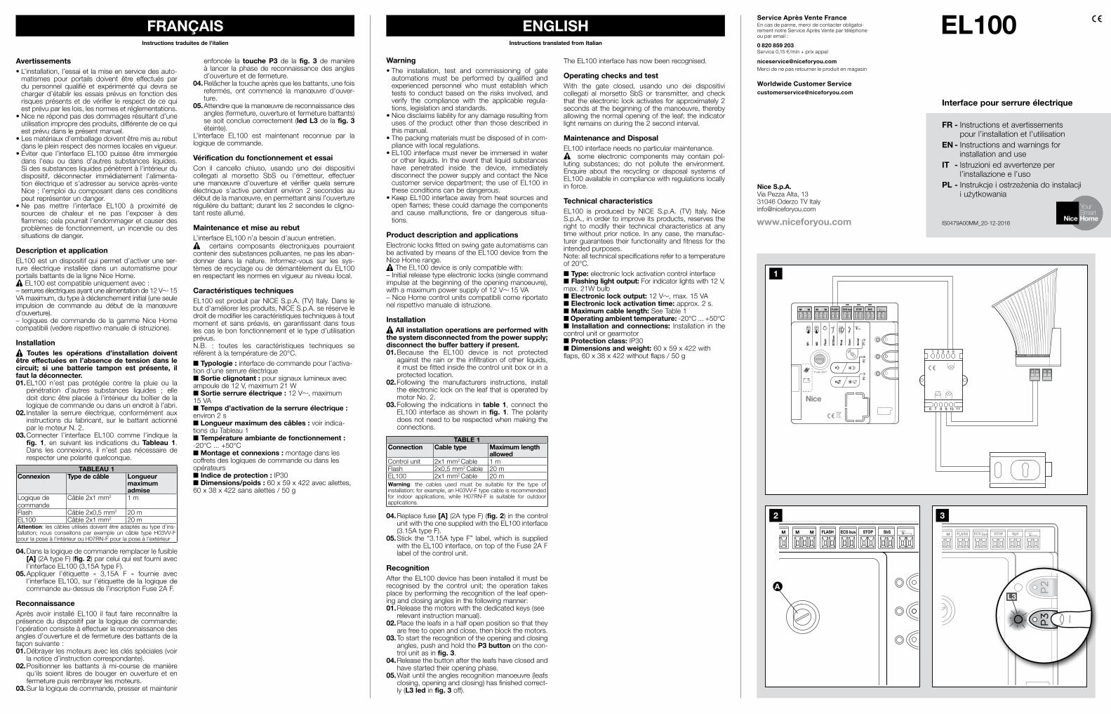
03. Following the indications in table 1, connect the EL100 interface as shown in fig. 1. The polaritydoes not need to be respected when making the connections.
TABLE 1Connection Cable type Maximum length
allowedControl unit 2x1mm2Cable 1 mFlash 2x0,5mm2Cable 20mEL100 2x1mm2Cable 20mWarning: the cables used must be suitable for the type ofinstallation;forexample,anH03VV-Ftypecableisrecommendedfor indoor applications, while H07RN-F is suitable for outdoor applications.
04. Replace fuse [A](2AtypeF) (fig. 2) in the control unit with the one supplied with the EL100 interface (3.15AtypeF).
05.Stick the “3.15A typeF” label,which is suppliedwiththeEL100interface,ontopoftheFuse2AFlabel of the control unit.
RecognitionAftertheEL100devicehasbeeninstalleditmustberecognised by the control unit; the operation takesplacebyperformingtherecognitionoftheleafopen-ingandclosinganglesinthefollowingmanner:01.Releasethemotorswiththededicatedkeys(see
relevant instruction manual).02.Placetheleafsinahalfopenpositionsothatthey
are free to open and close, then block the motors.03. To start the recognition of the opening and closing
angles, push and hold the P3 button on the con-trol unit as in fig. 3.
04. Release the button after the leafs have closed and have started their opening phase.
05.Waituntiltheanglesrecognitionmanoeuvre(leafsclosing, opening and closing) has finished correct-ly(L3 led in fig. 3 off).
The EL100 interface has now been recognised.
Operating checks and test With the gate closed, usando uno dei dispositivi collegati al morsetto SbS or transmitter, and check that theelectronic lockactivates forapproximately2secondsat thebeginningof themanoeuvre, therebyallowing the normal opening of the leaf; the indicator lightremainsonduringthe2secondinterval.
Maintenance and DisposalEL100 interface needs no particular maintenance. some electronic components may contain pol-
luting substances; do not pollute the environment. Enquire about the recycling or disposal systems ofEL100availableincompliancewithregulationslocallyin force.
Technical characteristicsEL100 is produced by NICE S.p.A. (TV) Italy. NiceS.p.A., inordertoimproveitsproducts,reservestheright to modify their technical characteristics at anytimewithoutpriornotice. Inanycase, themanufac-turerguaranteestheirfunctionalityandfitnessfortheintended purposes. Note:alltechnicalspecificationsrefertoatemperatureof20°C.■ Type: electronic lock activation control interface ■ Flashing light output:Forindicatorlightswith12V,max.21Wbulb■ Electronic lock output:12V ,max.15VA■ Electronic lock activation time:approx.2s.■ Maximum cable length: See Table 1■ Operating ambient temperature:-20°C...+50°C■ Installation and connections: Installation in the control unit or gearmotor■ Protection class: IP30■ Dimensions and weight:60x59x422withflaps,60x38x422withoutflaps/50g
EL100
IS0479A00MM_20-12-2016www.niceforyou.com
Nice S.p.A.ViaPezzaAlta,[email protected]
Service Après Vente FranceEn cas de panne, merci de contacter obligatoi-rementnotreServiceAprèsVentepartéléphoneouparemail:
0 820 859 203Service0,15€/min+prixappel
niceservice@niceforyou.comMercidenepasretournerleproduitenmagasin
Worldwide Customer [email protected]
FRANÇAIS ENGLISHInstructions traduites de l’italien Instructions translated from Italian
Avertissements• L’installation, l’essai et la mise en service des auto-matismes pour portails doivent être effectués pardu personnel qualifié et expérimenté qui devra sechargerd’établir lesessaisprévusen fonctiondesrisquesprésentsetdevérifier le respectdecequiestprévuparleslois,lesnormesetréglementations.
•Nicenerépondpasdesdommagesrésultantd’uneutilisationimpropredesproduits,différentedecequiestprévudansleprésentmanuel.
•Lesmatériauxd’emballagedoiventêtremisaurebutdans le plein respect des normes locales en vigueur.
•Éviter que l’interface EL100 puisse être immergéedans l’eau ou dans d’autres substances liquides.Sidessubstancesliquidespénètrentàl’intérieurdudispositif, déconnecter immédiatement l’alimenta-tionélectriqueets’adresserauserviceaprès-venteNice ; l’emploi du composant dans ces conditions peutreprésenterundanger.
•Ne pas mettre l’interface EL100 à proximité desources de chaleur et ne pas l’exposer à desflammes; cela pourrait l’endommager et causer des problèmes de fonctionnement, un incendie ou dessituations de danger.
Description et applicationEL100estundispositifquipermetd’activeruneser-rure électrique installée dans un automatisme pourportails battants de la ligne Nice Home.EL100estcompatibleuniquementavec:
–serruresélectriquesayantunealimentationde12V 15 VAmaximum,dutypeàdéclenchementinitial(uneseuleimpulsion de commande au début de la manœuvred’ouverture).– logiques de commandede la gammeNiceHomecompatibili(vedererispettivomanualediistruzione).
Installation Toutes les opérations d’installation doivent
être effectuées en l’absence de tension dans le circuit; si une batterie tampon est présente, il faut la déconnecter.01.EL100 n’est pas protégée contre la pluie ou la
pénétration d’autres substances liquides ; elledoitdoncêtreplacéeà l’intérieurduboîtierde lalogiquedecommandeoudansunendroitàl’abri.
02.Installer la serrure électrique, conformément auxinstructions du fabricant, sur le battant actionnéparlemoteurN.2.
03.Connecter l’interface EL100 comme l’indique lafig. 1, en suivant les indications du Tableau 1. Dans les connexions, il n’est pas nécessaire derespecterunepolaritéquelconque.
TABLEAU 1Connexion Type de câble Longueur
maximum admise
Logiquedecommande
Câble2x1mm2 1 m
Flash Câble2x0,5mm2 20mEL100 Câble2x1mm2 20mAttention: lescâblesutilisésdoiventêtreadaptésautyped’ins-tallation; nous conseillons par exemple un câble type H03VV-Fpourlaposeàl’intérieurouH07RN-Fpourlaposeàl’extérieur
04.Danslalogiquedecommanderemplacerlefusible[A](2AtypeF) (fig. 2)parceluiquiestfourniavecl’interfaceEL100(3,15AtypeF).
05.Appliquer l’étiquette « 3,15A F » fournie avecl’interfaceEL100,sur l’étiquettede la logiquedecommandeau-dessusdel’inscriptionFuse2AF.
ReconnaissanceAprès avoir installé EL100 il faut faire reconnaître laprésencedudispositifpar la logiquedecommande;l’opérationconsisteàeffectuerlareconnaissancedesangles d’ouverture et de fermeture des battants de la façonsuivante:01.Débrayerlesmoteursaveclesclésspéciales(voir
la notice d’instruction correspondante).02.Positionner les battants àmi-course demanière
qu’ils soient libres debouger en ouverture et enfermeturepuisrembrayerlesmoteurs.
03.Surlalogiquedecommande,presseretmaintenir
enfoncée la touche P3 de la fig. 3 demanièreà lancer la phasede reconnaissancedes anglesd’ouverture et de fermeture.
04.Relâcherlatoucheaprèsquelesbattants,unefoisrefermés, ont commencé la manœuvre d’ouver-ture.
05.Attendrequelamanœuvredereconnaissancedesangles(fermeture,ouvertureetfermeturebattants)sesoitconcluecorrectement(led L3 de la fig. 3 éteinte).
L’interface EL100 est maintenant reconnue par la logiquedecommande.
Vérification du fonctionnement et essaiCon il cancello chiuso, usando uno dei dispositivi collegati al morsetto SbS ou l’émetteur, effectuerune manœuvre d’ouverture et vérifier quela serrureélectrique s’active pendant environ 2 secondes audébutdelamanœuvre,enpermettantainsil’ouverturerégulièredubattant;durantles2secondeslecligno-tantresteallumé.
Maintenance et mise au rebutL’interface EL100 n’a besoin d’aucun entretien. certains composants électroniques pourraient
contenir des substances polluantes, ne pas les aban-donner dans la nature. Informez-vous sur les sys-tèmesderecyclageoudedémantèlementduEL100en respectant les normes en vigueur au niveau local.
Caractéristiques techniquesEL100estproduitparNICES.p.A.(TV)Italy.Danslebutd’améliorerlesproduits,NICES.p.A.seréserveledroitdemodifierlescaractéristiquestechniquesàtoutmoment et sans préavis, en garantissant dans touslescas lebon fonctionnementet le typed’utilisationprévus.N.B. : toutes les caractéristiques techniques seréfèrentàlatempératurede20°C.■ Typologie : interface de commande pour l’activa-tiond’uneserrureélectrique■ Sortie clignotant : pour signaux lumineux avec ampoulede12V,maximum21W■ Sortie serrure électrique :12V , maximum 15VA■ Temps d’activation de la serrure électrique : environ2s■ Longueur maximum des câbles : voir indica-tions du Tableau 1■ Température ambiante de fonctionnement : -20°C...+50°C■ Montage et connexions : montage dans les coffretsdeslogiquesdecommandeoudanslesopérateurs■ Indice de protection : IP30■ Dimensions/poids :60x59x422avecailettes,60x38x422sansailettes/50g
M M M M FLASH ECS bus STOP
M1
M2
Flas
h
ECSb
us
Stop
Ope
n
Aeria
l
SbS
1 2
6 7 8 9 10 11
3 4 5
1
M M M M FLASH ECS bus STOP SbSM M M M FLASH ECS bus STOP SbSM M M M FLASH ECS bus STOP SbS
P2
P3
3
L3
2
A

Avvertenze• L’installazione, il collaudo e la messa in servizio delle
automazioni per cancelli deve essere eseguita da personalequalificatoedespertochedovràfarsicari-co di stabilire le prove previste in funzione dei rischi presenti e verificare il rispettodiquantoprevistodaleggi, normative e regolamenti.
• Nice non risponde dei danni risultanti da un uso improprio del prodotto diverso da quanto previstonel presente manuale.
• Il materiale dell’imballaggio deve essere smaltito nel pieno rispetto della normativa locale.
• Evitare che l’interfaccia EL100 possa venir immersa inacquaoaltresostanzeliquide.Qualorasostanzeliquide siano penetrate all’interno del dispositivo,scollegare immediatamente l’alimentazione elettrica e rivolgersi al servizio assistenza Nice; l’uso del componente in tali condizioni può causare situazioni di pericolo.
• Non tenere l’interfaccia EL100 vicino a forti fonti di calore né esporla a fiamme; tali azioni possonodanneggiarla ed essere causa di malfunzionamenti, incendio o situazioni di pericolo.
Descrizione e destinazione d’usoEL100 è un dispositivo che consente di attivareun’elettroserratura installata in un automatismo per cancelli ad ante della linea Nice Home.EL100écompatibilesolamentecon:
– elettroserrature aventi tensione di alimentazione 12V 15VAmassimo,di tipoascatto iniziale (uni-co impulso di comando ad inizio della manovra di apertura).– centrali di comando della linea Nice Home compati-bili(vedererispettivomanualediistruzione).
Installazione Tutte le operazioni di installazione vanno
eseguite in assenza di tensione all’impianto; nel caso sia presente la batteria tampone, è neces-sario scollegarla.01.EL100nonèprotettacontrolapioggiaol’entrata
di altre sostanze liquide, pertanto deve essereposta all’interno del box della centrale di comando o in luoghi protetti.
02. Installare l’elettroserratura, come da istruzioni del produttore,sull’antaazionatadalmotoreN.2.
03. Collegare l’interfaccia EL100 come indicato in fig. 1, seguendo le indicazioni di Tabella 1. Nei collegamenti non è necessario rispettare alcunapolarità.
TABELLA 1Collegamento Tipo cavo Lunghezza
massima consentita
Centrale Cavo2x1mm2 1 mFlash Cavo2x0,5mm2 20mEL100 Cavo2x1mm2 20mAttenzione:icaviutilizzatidevonoessereadattialtipodiinstalla-zione;adesempiosiconsigliauncavotipoH03VV-Fperposainambienti interni oppure H07RN-F se posato all’esterno.
04. Nella centrale di comando sostituire il fusibile [A] (2A tipoF) (fig. 2)conquelloacorredodell’inter-facciaEL100(3,15AtipoF).
05. Applicare l’etichetta “3,15A tipo F” in dotazionecon l’interfaccia EL100, sull’etichetta della centrale dicomandosopralascrittaFuse2AF.
ApprendimentoDopo aver installato EL100 è necessario far ricono-scere alla centrale la presenza del dispositivo; l’opera-zione avviene eseguendo l’apprendimento degli angoli diaperturaechiusuradelleantenelseguentemodo:01.Sbloccare imotoricon leappositechiavi (vedere
rispettivo manuale istruzione). 02.Portare le anteametàcorsa inmodochesiano
libere di muoversi in apertura e chiusura, poi bloc-care i motori.
03. Sulla centrale, premere e tenere premuto il tasto P3 di fig. 3 in modo da avviare la fase di appren-dimento angoli apertura e chiusura.
04. Rilasciare il tasto dopo che le ante, una volta chiu-se, abbiano iniziato la manovra di apertura.
Ostrzeżenia•Montaż,próbaodbiorcza i przekazanie automatykido bram do eksploatacji powinno być wykonaneprzez wykwalifikowany i doświadczony personel,który powinien wykonać przewidziane testy, wzależności od istniejących zagrożeń i sprawdzićprzestrzeganieprzepisów,normirozporządzeń.
•FirmaNicenieodpowiadazaszkodywynikającezniewłaściwego używania urządzenia, odmiennegood przewidzianego w niniejszej instrukcji.
•Materiałopakowaniowynależyutylizowaćzgodniezlokalnymiprzepisami.
•Nie wolno zanurzać interfejsu EL100 w wodzielub innych cieczach. W przypadku przeniknięciajakiegoś płynu do środka urządzenia, należy nie-zwłocznie odłączyć zasilanie elektryczne i zwrócićsiędoserwisu firmyNice.Użytkowanieurządzeniawtakichwarunkachmożeprowadzićdozagrożenia.
•Interfejs EL100niemoże się znajdowaćwpobliżusilnych źródeł ciepła, czy płomieni. Może to pro-wadzić do jego uszkodzenia, pożarów lub sytuacjiniebezpiecznych.
Opis i przeznaczenieEL100 jest urządzeniem umożliwiającym aktywacjęzamkaelektrycznegozamontowanegowautomatycedobramskrzydłowychliniiNiceHome.UrządzenieEL100jestkompatybilnewyłączniez:
–zamkamielektrycznymizmaksymalnymnapięciemzasilaniawynoszącym12V 15VA,zpoczątkowymimpulsem (jeden impuls sterowniczy na początkumanewru otwierania).– kompatybilnymi centralami sterującymi linii NiceHome(patrzodpowiedniainstrukcjaobsługi).
Montaż Wszystkie czynności montażowe należy
wykonywać po odłączeniu centrali od zasila-nia; w razie obecności akumulatora awaryjnego należy go odłączyć.01.UrządzenieEL100niejestchronioneprzeddesz-
czemlubprzeciekanieminnychcieczy,więcnależyjeumieścićwewnętrzuskrzynkicentralisterującejlubwmiejscuchronionym.
02. Zamontowaćzamekelektrycznyzgodniezinstruk-cją producenta na skrzydle napędzanym przezsilniknr2.
03. Podłączyć interfejs EL100 zgodnie z rys. 1, zgodnie ze wskazówkami w Tabeli 1. Podczas podłączania nie jest konieczne przestrzeganiebiegunowości.
TABELA 1Połączenie Rodzaj przewodu Maksymalna
dozwolona długość
Centrala Przewód2x1mm2 1 mFlash Przewód2x0,5mm2 20mEL100 Przewód2x1mm2 20mUwaga:zastosowaneprzewodypowinnyodpowiadaćrodzajowiinstalacji,naprzykładzalecasięprzewódtypuH03VV-Fdoinsta-lowania we wnętrzach lub przewód H07RN-F do instalowanianazewnątrz.
04. Wcentralisterującejwymienićbezpiecznik[A](2AtypF) (rys. 2)nabezpiecznikdołączonydo inter-fejsuEL100(3,15AtypF).
05. Zastosowaćetykietę„3,15AtypF”dołączonądointerfejsu EL100, na etykiecie centrali sterującejpowyżejnapisu„Fuse2AF”.
WczytywaniePozainstalowaniuEL100należysprawić,bycentralarozpoznałaobecnośćurządzenia;działanietoodbywasię wykonując odczyt kątów otwierania i zamykaniaskrzydełwnastępującysposób:01.Odblokowaćsilnikizapomocąodpowiednichklu-
czy(patrzodpowiedniainstrukcjaobsługi).02.Przenieśćskrzydłanapołowęskokuwsposóbtaki,
by mogły się swobodnie przemieszczać podczasotwieraniaizamykania,następniezablokowaćsilniki.
03.Na centrali, nacisnąć i przytrzymać wciśniętyprzycisk P3 na rys. 3 w sposób umożliwiającywłączenie fazy wczytywania kątów otwierania izamykania.
05.Attenderechelamanovradiapprendimentoangoli(chiusura,aperturaechiusuraante)sisiaconclusacorrettamente(led L3 di fig. 3 spento).
A questo punto l’interfaccia EL100 è stata ricono-sciuta.
Verifica del funzionamento e collaudoCon il cancello chiuso, usando uno dei dispositivi collegati al morsetto SbS o il trasmettitore, eseguire una manovra di apertura e verificare che, ad inizio manovra,siattivil’elettroserraturapercirca2secondi,permettendo così l’apertura regolare dell’anta; duran-tei2secondiillampeggianterimaneacceso.
Manutenzione e smaltimentoL’interfaccia EL100 non necessita di alcuna manu-tenzione.
alcuni componenti elettronici potrebbero contenere sostanze inquinanti, non disperderli nell’am-biente. Informatevi sui sistemi di riciclaggio o smaltimento di EL100 attenendovi alle norme in vigore a livello locale.
Caratteristiche TecnicheEL100èprodottodaNiceS.p.A.(TV)Italy.Alloscopodimigliorare iprodotti,NiceS.p.A.si riserva ildirittodi modificare le caratteristiche tecniche in qualsiasimomentoesenzapreavviso,garantendocomunquefunzionalitàedestinazioned’usopreviste.Nota:tuttelecaratteristichetecnichesonoriferiteallatemperaturadi20°C.
■ Tipologia: interfaccia di comando per attivazione di una elettroseratura■ Uscita lampeggiante: Per segnalatori luminosi conlampadada12V,massimo21W■ Uscita elettroserratura:12V ,massimo15VA■ Tempo di attivazione elettroserratura: circa 2secondi■ Lunghezza massima cavi: vedere indicazioni di Tabella 1■ Temperatura ambientale di funzionamento: -20°C...+50°C■ Montaggio e collegamenti: Inserimento nei vani delle centrali o motoriduttori■ Grado di protezione: IP30■ Dimensioni / peso:60x59x422conalette,60x38x422senzaalette/50g
04.Zwolnićprzyciskpotym,jakskrzydła,pozamknię-ciu,rozpocznąmanewrotwierania.
05.Odczekać na prawidłowe zakończenie manewruwczytywaniakątów(zamykanie,otwieranieizamy-kanieskrzydeł)(zgaszona dioda L3 na rys. 3).
WtejchwiliinterfejsEL100zostałwczytany.
Kontrola działania i próba odbiorczaZzamkniętąbramą,przyużyciu jednegozurządzeńpodłączonych do listwy zaciskowej SbS lub nadaj-nika, wykonać manewr otwierania i sprawdzić, czyna początku manewru, nastąpi aktywacja zamkaelektrycznego na około 2 sekundy, umożliwiając wten sposób prawidłowe otwarcie skrzydła;w tych 2sekundach lampa ostrzegawcza pozostanie zaświe-cona.
Konserwacja i utylizacjaInterfejs EL100 nie wymaga specjalnych czynnościkonserwacyjnych. Niektóre elementy elektroniczne mogą zawierać
szkodliwe substancje: nie należy ich wyrzucać dośrodowiska. Zapoznać się ze sposobami recy-klingu lubutylizacjiEL100 idostosowaćsiędoaktualnieobowiązującychwtymzakresienormlokalnych.
Charakterystyka technicznaEL100 jestproduktemfirmyNiceS.p.A. (TV) Italy.Wceluulepszeniaswoichproduktów,spółkaNiceS.p.A.zastrzega sobie prawo do wnoszenia zmian technicz-nychw którymkolwiekmomencie i bez uprzedniegopowiadomienia,gwarantującprzewidzianąfunkcjonal-nośćiprzeznaczenieużytkowania.Uwaga: charakterystyka techniczna odnosi się dotemperatury20°C.
■ Typologia:interfejssterowniczydoaktywacjizam-kaelektrycznego■ Wyjście lampy ostrzegawczej: Dla urządzeńsygnalizacji optycznej z żarówką12Vomocymak-symalnej21W■ Wyjście zamka elektrycznego: 12V ,maksy-malnie15VA■ Czas aktywacji zamka elektrycznego:około2sekundy■ Maksymalna długość kabli:patrzwskazówkiwTabeli 1■ Temperatura robocza otoczenia: -20°C ... +50°C■ Montaż i podłączenia:Montażwodpowiednichkomorachcentralilubmotoreduktorów■ Stopień ochrony: IP30■ Wymiary / masa:60x59x422złopatkami,60x38x422bezłopatek/50g
FR - Déclaration de conformitéDéclarationconformeàlaDirective2014/30/CE(CME)Note : le contenu de cette déclaration correspond à ce qui a été déclaré dans le document officiel déposé au siège social de Nice S.p.A. et, en particulier, à la dernière mise à jour disponible avant l’impression de ce manuel. Le présent texte a été réadapté pour des raisons d’édition. Une copie de la déclaration originale peut être demandée à Nice S.p.A. (TV) Italy.
Numéro :577/EL100Révision : 0
Nom du producteur :NICES.p.A.Adresse :ViaPezzaAltan°13,31046RustignèdiOderzo(TV)ItalyType de produit:KitpourVerrouillageélectriqueNice HomeModèle :EL100Accessoires :Le soussigné Roberto Griffa en sa qualité deChief ExecutiveOfficer, déclare sous son entièreresponsabilité que le produit indiqué ci-dessusest conforme aux dispositions prescrites par les directivessuivantes:• DIRECTIVE 2014/30/UE du PARLEMENTEUROPÉENETDUCONSEILdu26 février2014relativeaurapprochementdeslégislationsdesÉtatsmembresconcernantlacompatibilitéélectromag-nétique (refonte), selon les normes harmoniséessuivantes:EN61000-6-1:2007,EN61000-6-3:2007+A1:2011
Oderzo,le28juillet2016Ing. Roberto Griffa
(ChiefExecutiveOfficer)
IT - Dichiarazione di conformitàDichiarazioneinaccordoallaDirettiva2014/30/UE(EMC)Nota – Il contenuto di questa dichiarazione corrisponde a quanto dichiarato nel documento ufficiale depositato pres-so la sede di Nice S.p.A. e, in particolare, alla sua ultima revisione disponibile prima della stampa di questo manuale. Il testo qui presente è stato riadattato per motivi editoriali. Copia della dichiarazione originale può essere richiesta a Nice S.p.A. (TV) Italy.
Numero:577/EL100Revisione: 0
Nome produttore:NICES.p.A.Indirizzo:ViaPezzaAltan°13,31046RustignèdiOderzo(TV)ItalyTipo di prodotto:KitperelettroserraturaNiceHomeModello:EL100Accessori:Il sottoscritto Roberto Griffa in qualità diAmministratoreDelegato,dichiarasottolapropriaresponsabilitàcheilprodottosopraindicatorisultaconforme alle disposizioni imposte dalle seguenti direttive:• DIRETTIVA 2014/30/UE DEL PARLAMENTOEUROPEO E DEL CONSIGLIO del 26 febbraio2014 concernente l’armonizzazione delle legisla-zioni degli Statimembri relative alla compatibilitàelettromagnetica (rifusione), secondo le seguentinormearmonizzate:EN61000-6-1:2007,EN61000-6-3:2007+A1:2011
Oderzo,28Luglio2016Ing. Roberto Griffa
(AmministratoreDelegato)
EN - Declaration of conformityDeclarationofconformityinaccordancewithDirective2014/30/EU(EMC)Note - The contents of this declaration correspond to that stated in the official document filed in the offices of Nice S.p.A. and, in particular, the latest version thereof available prior to the printing of this manual. The text herein has been re-edited for editorial purposes. A copy of the original declaration can be requested from Nice S.p.A. (TV) Italy.
Number:577/EL100Revision: 0
Manufacturer’s name:NICES.p.A.Address:ViaPezzaAltan°13,31046RustignèdiOderzo(TV)ItalyProduct type:ElectriclockkitbyNiceHomeModel:EL100Accessories:TheundersignedRobertoGriffa,asChiefExecutiveOfficer,herebydeclaresunderhisownresponsibi-litythattheproductidentifiedabovecomplieswiththeprovisionsofthefollowingdirectives:• DIRECTIVE 2014/30/EU OF THE EUROPEANPARLIAMENT AND OF THE COUNCIL of 26February 2014 on the harmonisation of the lawsof theMemberStates relating toelectromagneticcompatibility (recast), in accordancewith the fol-lowingharmonisedstandards:EN61000-6-1:2007,EN61000-6-3:2007+A1:2011
Oderzo,28July2016Ing. Roberto Griffa
(ChiefExecutiveOfficer)
PL - Deklaracja zgodnościDeklaracjazgodnazDyrektywą2014/30/WE(EMC)Uwaga – Zawartość niniejszej deklaracji zgodności odpowiada oświadczeniom znajdującym się w oficjalnym dokumencie złożonym w siedzibie firmy Nice S.p.A., w szczególności ostatnim zmianom dostępnym przed wydru-kowaniem niniejszej instrukcji. Niniejszy tekst został dosto-sowany w celach wydawniczych. Kopię oryginalnej dekla-racji można uzyskać w siedzibie spółki Nice S.p.A. (TV) Italy.
Numer:577/EL100 Wydanie: 0
Nazwa producenta:NICES.p.A.Adres:ViaPezzaAltan°13,31046RustignèdiOderzo(TV)ItalyTyp produktu:ZestawdozamkaelektrycznegoNice HomeModel:EL100Urządzenia dodatkowe:Ja, niżej podpisany Roberto Griffa jako ChiefExecutive Officer, oświadczam na własnąodpowiedzialność, że wyżej wymieniony produktjestzgodnyznastępującymidyrektywami:•DYREKTYWAPARLAMENTUEUROPEJSKIEGOIRADY2014/30/UEz26lutego2014r.wsprawieharmonizacjiustawodawstwpaństwczłonkowskichwzakresiezgodnościelektromagnetycznej(wersjaprzekształcona),zgodnieznastępującyminormamizharmonizowanymi:EN61000-6-1:2007,EN61000-6-3:2007+A1:2011
Oderzo,28lipiec2016 Inż.Roberto Griffa
(ChiefExecutiveOfficer)
ITALIANO POLSKIIstruzioni originali Instrukcja przetłumaczona z języka włoskiego