FRAME RELAY - eeedocs.files.wordpress.com › 2014 › 02 › frame... · The link layer of frame...
26
EE6364 DCW FR-1 FRAME RELAY CONTENTS 1. Frame Relay • Protocol and Frame Format • Operation 2. Multiprotocol Interconnection over Frame Relay 3. Frame Relay/ ATM Network Interworking
Transcript of FRAME RELAY - eeedocs.files.wordpress.com › 2014 › 02 › frame... · The link layer of frame...

EE6364
DCW FR-1
FRAME RELAY
CONTENTS 1. Frame Relay
• Protocol and Frame Format • Operation
2. Multiprotocol Interconnection over Frame Relay 3. Frame Relay/ ATM Network Interworking
EE6364
DCW FR-2
WHAT IS FRAME RELAY Frame relay is a fast packet switching. It has gained widespread support among vendors, users and network providers. Frame relay can be viewed as a simplified version of X.25. Unlike X.25 which was designed for low speed and high error rate transmission facilities, frame relay is designed for high speed and "error free" transmission facilities. It eliminates a lot of overhead, such as error correction, that is performed by X.25. In stead, it assumes that the end systems will perform those overhead. The frame relay protocol specified by the standards organizations is for the interface between the user and the network only. The mechanism of transporting the frame relay frames inside the network is up to the network provider. The basic bearer service provided by the network is order-preserving transfer of frames from the network side of one user-network interface to the network side of the other user-network interface. The frame is routed through the network on the basis of an attached label. This label is a logical identifier with local significance. Specifically, for each connection, the bearer service: (1) provides bi-directional transfer of frames. (2) Preserves the order as given at one user-network interface if and
when they are delivered at the other end. (3) Detect transmission, format, and operational errors (e.g., frames
of unknown labels). (4) Transport the user data contents of a frame transparently. (5) Does not acknowledge frames.

EE6364
DCW FR-3
FRAME RELAY NETWORK Like X.25, frame relay protocol defines the interface between user equipment and the network that transports the frames. It does not define the transport mechanism inside the network. Network providers may use different protocols to transport the user frames.
For example, the network may use ATM to transport the frames received from the users. Or, the networks may transport the whole frames as received. Those networks that use the switches which are modified from the X.25 switches transport the whole frames as received.

EE6364
DCW FR-4
USER-NETWORK INTERFACE PROTOCOL REFERENCE MODEL
Core functions of Q.921 are: (1) Frame delimiting, alignment and transparency provided by the
user of HDLC and zero-bit insertion. (2) Virtual circuit multiplexing/demultiplexing using address field of
the frame. (3) Inspection of the frame to ensure that it consists of an integer
number of octets prior to zero-bit insertion or following zero-bit extraction.
(4) Inspection of frames to ensure that it is not too short or too long. (5) Detection of transmission, format, and operation errors.
EE6364
DCW FR-5
FRAME RELAY AND OSI REFERENCE MODEL
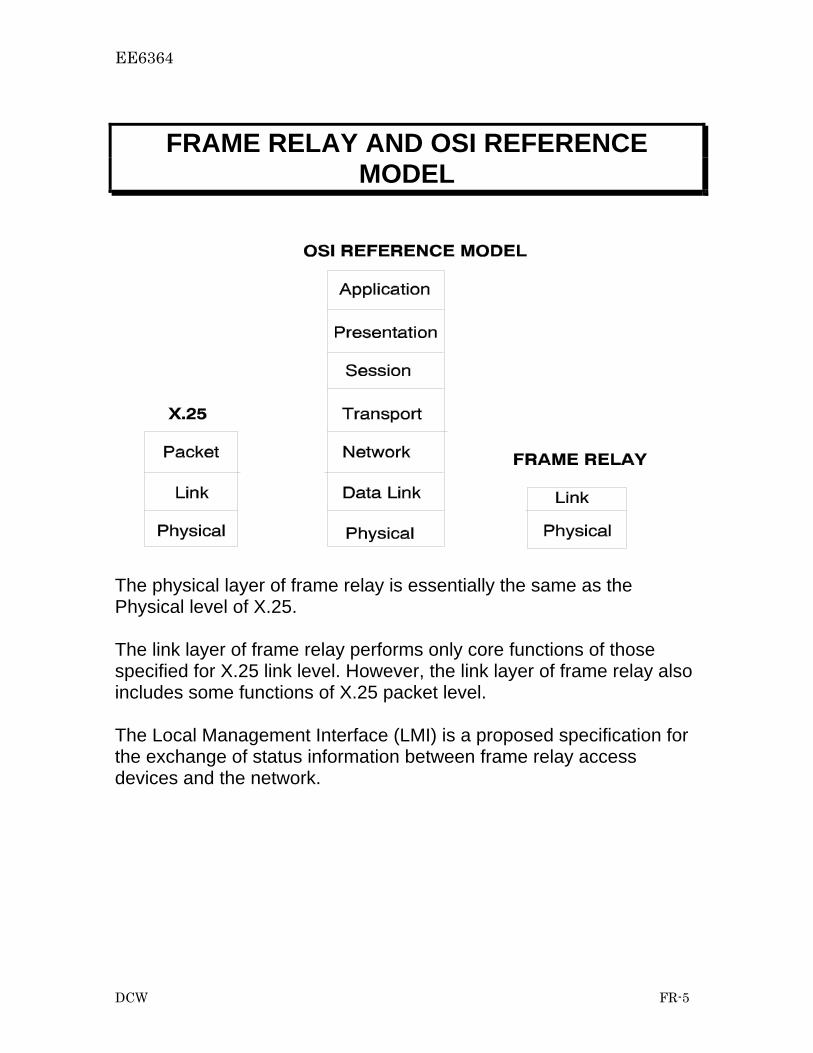
The physical layer of frame relay is essentially the same as the Physical level of X.25. The link layer of frame relay performs only core functions of those specified for X.25 link level. However, the link layer of frame relay also includes some functions of X.25 packet level. The Local Management Interface (LMI) is a proposed specification for the exchange of status information between frame relay access devices and the network.

EE6364
DCW FR-6
FRAME RELAY PHYSICAL LAYER The physical layer of frame relay is based on existing standards and depends on the equipment and the access speed used by the users.
The access speeds can be 56 Kb/s or lower. A non-channelized T1 line can provide 1.344 Mb/s bandwidth employing super frame format or 1.536 Mb/s bandwidth employing extended superframe format.
EE6364
DCW FR-7
FRAME RELAY DATA LINK LAYER Link layer uses the services of the physical layer. It, in turn, provides the following services to the upper layer: Flag recognition Frame check sequence (FCS) generation and checking Recognition of invalid frames Discard incorrect frames Routing Congestion control notification

EE6364
DCW FR-8
FRAME RELAY FRAME FORMAT
The maximum information field length should be at least 1600 octets. The generator polynomial is X16 + X12 + X5 +1 . For the frame relay bearer service, there is no control field in the frame relay frame.

EE6364
DCW FR-9
FRAME HEADER FORMAT The header can be extended to include more bits for the DLCI.
D/C
D/C
Or DL-Core Control
Or DL-Core ControlOr DL-Core Control
Information FCS

EE6364
DCW FR-10
FRAME HEADER Data Link Connection Identifier (DLCI): The DLCI is used to identify the logical connection, multiplexed
within the physical channel, with which a frame is associated. Bit 8 of the first octet is the most significant bit.
Command/Response (C/R) Indication: Not used by the DL-CORE protocol. The use of this bit is
application specific. Extended Address (EA): Included in the header to allow DLCIs to be longer than 10 bits.
For the standard 10 bit DLCI, the first EA bit is set to "0" and the second EA bit to "1".
Discard Eligibility (DE): Indicates frame priority. If this bit is set to 1, the frame is
considered a low priority frame. A switch should discard this frame in a congested situation before discarding other higher priority frames.
Forwarded Explicit Congestion Notification (FECN): This bit may be set to "1" by a switch to indicate to the receiving
user equipment that the connection has experienced congestion as the frame traversed the network.
Backward Explicit Congestion Notification (BECN): This bit may be set to "1" by the switch to indicate to the
transmitting user equipment that the frames it transmitted on a connection have encountered congestion.
D/C If bit is set to 0, the remaining six bits are the lower order DLCI. It
this bit is set to 1, the remaining six bits contain data-link core control information, which has not been defined yet.

EE6364
DCW FR-11
ADDRESSING Valid DLCIs for two-octet addresses:
Range Usage 0 In-channel signaling
1-15 Reserved 16-991 Assigned to connections
992-1007 Layer 2 management of frame relay bearer service 1008-1022 Reserved
1023 In channel layer management Currently, standards support both PVC and SVC. However, most frame relay services support PVC only. For a SVC, the DLCI is assigned during call setup process. For PVCs, DLCIs are assigned by the network providers at the subscription time.

EE6364
DCW FR-12
CONGESTION VS. OFFERED-LOAD When the network starts to be congested (region II), the throughput plateaus and delay starts to increase quickly. When the network is severely congested (region III), the throughput drops dramatically and delay increases quickly. By using congestion control, the performance degradation may be lessened.
No Congestionwithin Network
MildCongestion
SevereCongestion
Region I Region II Region III
Offered Load
Net
wor
k T
hrou
ghpu
t
A B
No Congestionwithin Network
MildCongestion
SevereCongestion
Region I Region II Region III
Offered Load
Del
ay
AB

EE6364
DCW FR-13
COMMITTED INFORMATION RATE, COMMITTED
BURST SIZE, AND EXCESSIVE BURST SIZE
A c c e s sR a te
C IR
B c
B c + B e
B its
T 0 T 0 + T
F r a m e 1 F r a m e 2 F r a m e 3 F r a m e 4U s e rA c tiv i ty
M e a s u re m e n tIn t e r v a l
Three parameters have been defined. They are: CIR: committed information rate Bc: committed burst size Be: excessive burst size
EE6364
DCW FR-14
CONGESTION MANAGEMENT Frame relay congestion management includes network engineering, OA&M procedures to detect the onset of congestion, and real-time mechanism to prevent or recover from congestion. real time congestion management procedures may include congestion control. Congestion control includes congestion avoidance and congestion recovery mechanisms. Congestion avoidance initiation is the joint responsibility of the network and users. Congestion avoidance uses explicit notification. Congestion recovery initiation is the responsibility of the network. Explicit congestion notification is a process by which the network sends a signal to end-user to notify them of congestion within the network. Implicit congestion detection is a inference by user equipment that the network is congested, based on determination by upper layers that one or more frames have been lost.

EE6364
DCW FR-15
CONGESTION AVOIDANCE METHODS 1. FECN and BECN: Traffic No Congestion Congestion A →B
and B → A A → B B → A
FECN BECN 0 0 0 0
FECN BECN 1 1 1 1
Traffic Congestion A → B No Congestion B →A
Congestion B → A No Congestion A → B
A → B B → A
FECN BECN 1 0 0 1
FECN BECN 0 1 1 0
2. DE Bit: The ingress switch set the DE bit on frames that exceed the committed information rate (CIR). These frames are considered low priority and may be dropped when congestion starts to occur. 3. Consolidated Link Layer Management (CLLM): Uses DLCI 1023 to send frames to user equipment to notify the occurrence of congestion.

EE6364
DCW FR-16
USER RESPONSE TO FECN Users should compare the number of received frames in which the FECN bits is set with the number of received frames in which the FECN bit is cleared, over a measurement interval. If the number of set FECN bits is equal or exceeds the number of clear FECN bits received during this period, then the user shall reduce its current throughput to 7/8 of its previous value. If the number of the set FECN bits is less than the number of clear FECN bits, then the user may increase its information rate by 1/16 of its throughput. If the user has the capability to determine that a frame has been lost, reaction should be implemented to this loss. Upon determining that a frame has been dropped, the user should reduce its offered rate to 0.25 times the previous value. If no frames received during the measurement interval were received with FECN bit set, there is a moderate likelihood that the frame loss is due to transmission error and not congestion. In such case, the offered throughput should be reduced to 0.625 times its previous value. The user may increase its throughput by a factor of 1/8 times throughput after a measurement interval in which no further frame loss is detected. Once this throughput reaches 0.5 times the value in use when the initial frame loss was detected, this increase factor should change to 1/16 times throughput.

EE6364
DCW FR-17
RESPONSES TO BECN For use with BECN mechanism, a step count, S, is defined. S is used to determine when the transmitter may increase or decrease its rate, based on the state of BECN bits received.
88
f
ff
fff
ArBcBe
BeThIR ⎟
⎟⎠
⎞⎜⎜⎝
⎛
++=
88
b
bb
bbb
ArBcBe
BeThIR ⎟⎟⎠
⎞⎜⎜⎝
⎛+
+=
⎟⎟⎠
⎞⎜⎜⎝
⎛+=
bb
ff
f
b
NEETDIR
NEETDIR
FFS
202202
where IRf the information rate in the forward direction; IRb the information rate in the backward direction; S step count; Thf agreed throughput in the forward direction; Thb agreed throughput in the backward direction; EETD end-to-end transit delay; N202f the maximum information field length in the forward direction; N202b the maximum information field length in the backward direction; Arf the forward access rate; Arb the backward access rate; Bef excessive burst size forward; Beb excessive burst size backward; Bcf committed burst size forward; Bcb committed burst size backward; Fb/Ff ratio of frames received to frame sent. If a frame with a BECN bit is received, and the user’s offered rate is greater than the agreed throughput, the user should reduce its offered rate to the agreed throughput.

EE6364
DCW FR-18
RESPONSES TO BECN (CONTINUE) If S consecutive frames are received with the BECN bits set, the user should reduce its rate to the next step rate below the current offered rate. Further reduction should not occur until an additional S consecutive frames are received with BECN bit set. The step rate are: 0.675 times throughput 0.5 times throughput 0.25 times throughput When the user has reduced its rate due to receipt of BECN, it may increase its rate by a factor of 1/8 times throughput after any S/2 consecutive frames are received with BECN bit clear. Upon determining that a frame has been dropped, the user should reduce its offered rate to 0.25 times throughput if the rate is presently reduced due to explicit congestion notification, or if the network is not known to provide BECN. If the network provides explicit congestion notification and no frames received during the measurement interval were received with BECN bit set, there is a moderate likelihood that the frame loss is due to transmission error and not congestion. In such case, the offered throughput should be reduced to 0.625 times its previous value. When the user has reduced its rate due to frame loss, it may increase its rate by a factor of 1/8 times throughput after any S/2 consecutive frames are received with BECN bit clear.

EE6364
DCW FR-19
SWITCHED VIRTUAL CIRCUIT (SVC) Frame relay can support both permanent virtual circuits (PVCs) and switched virtual circuits (SVCs). PVCs are manually provisioned by the service providers and are readily available when users need them. No call setup is necessary for PVCs. SVCs require call setup. Frame relay uses ITU-T standard Q.933 message set for call setup. The Q.933 messages are transmitted from the user to the network and vice versa using Q.922 protocol. These messages are sent using DLCI=0. Both Q.922 core and control functions are required to send Q.933 messages. We have discussed the core functions which are performed by the address field. The control field, which is 1 or 2 bytes long, performs the control functions. The format of the Q.933 messages is
The format of the control field is
Flag Address Control Q.933 message FCS Flag
No.Bytes 1 2 1-2 2 1
1 2 3 4 5 6 7 8 9 10 11 12 13 14 15 16
0 N(S) P/F N(R)
1 0 S S 0 0 0 P/F N(R)
1 1 M M P/F M M M
0
InformationTransfer
Supervisory
Unnumbered
Bit

EE6364
DCW FR-20
The Q.9333 messages used for call setup include SETUP, CONNECT, CONNECT ACKNOWLEDGEMENT, DISCONNECT, RELEASE, and RELEASE ACKNOWLEDGEMENT. Each message contains a set of parameters that are needed. For example, SETUP contains calling and called party numbers. The call setup and disconnect processes are
FRADFRAD FRADFRADFrame Relay Network
SetupSetup
Connect
Connect Ack
Connect
Connect Ack
Disconnect
Release
Release Ack
Disconnect
Release
Release Ack

EE6364
DCW FR-21
MULTIPROTOCOL INTERCONNECT OVER FRAME RELAY1
Frame relay frames transport packets, which include the protocol headers and data, in the information field. In another word, these packets are encapsulated by the frame relay frames. Examples are IP v4 or v6 packets, Ethernet packets, PPP packets, etc. They can be categorized into routed packets and bridged packets. The address field of the frame header does not contain any information about the data in the information field. An indicator is needed in the information field, so that the destination may be able to correctly interpret the information (i.e., the packet) received. The general frame format is
1. C. Brown and A. Malis, “Multiprotocol Interconnect over Frame Relay,” RFC 2427, September 1998.
Flag (0x7e)
Q.922 Address
Control (0x03)
Pad (if needed 0x00)
NLPID
Data
Frame Check Sequence
Flag (0x7e)

EE6364
DCW FR-22
NLPID is the network level protocol ID. It is one byte long. For some protocols, the protocol ID is two bytes long. Then SNAP is used. In that case following NLPID are three bytes of OUI (organization unique ID) and two bytes of PID (protocol ID), where OUI indicates the organization that controls the PID. The frame format for encapsulating routed IP packets or PPP packet is
Note that this is the format of encapsulating routed packets into frame relay frames.
Flag (0x7e)
Q.922 Address
Control (0x03)
NLPID 0xCC( IPv4) 0x8E (IPv6) 0xCF (PPP)
Data
Frame Check Sequence
Flag (0x7e)
IP (v4 or v6) or PPP Header

EE6364
DCW FR-23
The format of encapsulating bridged packets into frame relay frames is
Note that this is the format of encapsulating the bridged packet into a frame relay frame. Thus, the MAC addresses are included in the frame.
Flag (0x7e)
Q.922 Address
Control (0x03)
Remaining MAC frame
Frame Check Sequence
Flag (0x7e)
Pad (0x00)
NLPID (0x80)
MAC Header
OUI (0x00)
OUI (0x80)
OUI (0xC2)
PIDPID
SNAP
IEEE802.1Org.
MAC frameStarting fromDestinationaddress

EE6364
DCW FR-24
Some commonly used NLPID are: 0x08 Q.933 0x80 SNAP 0x81 ISO CLNP 0x8E IPv6 0xB0 RFR.9 Data Compression 0xCC IPv4 0xCF PPP List of some PIDs for OUI 00-80-C2 With preserved FCS w/o preserved FCS Media 0x00-01 0x00-07 802.3/etherent 0x00-02 0x00-08 802.4 0x00-03 0x00-09 802.5 0x00-04 0x00-0A FDDI
0x00-0B 802.6

EE6364
DCW FR-25
FRAME RELAY/ATM NETWORK INTERWORKING2
Most of the network service providers are transporting frame relay traffic over their ATM networks. The following figure shows a frame relay/ATM network interworking, and the protocol stack. The frame relay/ATM interworking function (IWF) is a set of functions required to support the transmission of frame relay frames across the ATM nework. The IWF could be implemented at the edge switch of the ATM network. At the ingress, the IWF converts the various size frame relay frames into fix-size ATM cells. At the egress, the process is reversed. 2. Frame Relay Forum FRF.5, Frame Relay/ATM PVC Network Interworking Implementation Agreement, Dec., 1994.
IWF
IWF
IWF
IWF
IWF
IWF
IWF
IWFFrame Relay
Network
Frame RelayNetwork
ATMNetwork
FR UNI
FR UNI
Q.922Core
FR-SSCSCPCSSARATM
Phy Phy.
Q.922Core
FR-SSCSCPCSSARATM
Phy Phy.Phy
Q.922Core
UpperLayer
Phy
Q.922Core
UpperLayer
ATM ATM
Phy Phy
ATM ATM
Phy Phy
Q.922Core
FR-SSCSCPCSSARATM
PhyPhy.
Q.922Core
FR-SSCSCPCSSARATM
PhyPhy. Phy
Q.922Core
UpperLayer
Phy
Q.922Core
UpperLayer

EE6364
DCW FR-26
The frame relay service features supported by the IWF include: • Variable length PDU formatting and delimiting • Error detection • Connection multiplexing • Loss priority indication • Congestion indication (forward and backward) • PVC status management
The frame relay service specific convergence sublayer (FR-SSCS) uses a PDU format identical to Q.922 core without the CRC-16, flags and the zero bit insertion. AAL5 is used to convert the FR-SSCS PDU into ATM cells. The AAL5 common part convergence sublayer (CPCS) appends pad (0 to 47 bytes) and CPCS-PDU trailer, which includes a four-byte CRC, to the PDU. The SAR function segments the CPCS-PDU into ATM cells. The IWF error detection is supported by the use of four-byte CRC at the trailer. The FR-SSCS supports connection multiplexing using the DLCI. The ATM layer supports connection multiplexing using its VPI/VCI. If one-to-one multiplexing is supported, each FR logical connection is mapped to a single ATM virtual channel connection (VCC). Multiple FR logical connections can be multiplexed into a single ATM VCC. Multiplexing is accomplished at the FR-SSCS using DLCIs.