
Fracture resistance of monolithic zirconia crowns with ... · minimal thickness of a complete...
8
RESEARCH AND EDUCATION Fracture resistance of monolithic zirconia crowns with different occlusal thicknesses in implant prostheses Ting-Hsun Lan, DDS, MDS, a Pao-Hsin Liu, PhD, b Mitch M. C. Chou, PhD, c and Huey-Er Lee, DDS, MS, PhD d Zirconia was first used in the medical field to produce artifi- cial femoral heads. 1 Since the early 1990s, however, applica- tions have expanded, particu- larly into the implant field of dentistry. Zirconia has high mechanical toughness, supe- rior esthetic properties, and desirable biocompatibility. 2 Zir- conia implants have exhibited a bone-implant-contact com- parable with that of titanium implants 3-5 and enhanced bone-implant-contact in ani- mal studies. 6 A popular clinical application that affects the light reflection of the supporting soft tissue is the zirconia abutment composition, 7 such as the computer-aided design/com- puter-aided manufacturing (CAD/CAM) complete zirco- nia abutment, zirconia friction-fit to a titanium abutment, and zirconia bonded to titanium. 8 Recently, complete zirconia monolithic crowns and fixed dental prostheses have gained attention 9-11 because of their good mechan- ical properties, low wear of the enamel antagonist, 12 and lack of metal color. They also reduce the major clinical complications that result from the fracturing of veneering porcelain and zirconia frameworks, 13 particularly in an implant prosthesis. Although zirconia has a relatively high elastic modulus (215 GPa) and high flexure strength (1000 MPa) that exceed those of many metal alloys, clinicians and technicians suggest that the minimal thickness for nat- ural dentition should be 0.5 mm. 14 Comparisons of different ceramic specimens by Lawn et al 15 and Deng Funded by the NSYSU-KMU Joint Research Project (NSYSUKMUP014, NSYSUKMU103-P003). T.-H.L. and H.-E.L. contributed equally to this article. a Attending Dentist, Department of Dentistry, Kaohsiung Medical University Hospital, Kaohsiung Taiwan; Assistant Professor, School of Dentistry, College of Dental Medicine, Kaohsiung Medical University, Kaohsiung, Taiwan. b Assistant Professor, Department of Biomedical Engineering, I-Shou University, Kaohsiung, Taiwan. c Professor, Department of Materials & Opto-electronic Science, National Sun Yat-Sen University, Kaohsiung, Taiwan. d Professor, School of Dentistry, College of Dental Medicine, Kaohsiung, Taiwan. ABSTRACT Statement of problem. The use of monolithic zirconia crowns in implant prostheses is increasing, especially when the interdental space is insufficient. However, fractures have been reported in clinical practice. Purpose. The purpose of this study was to determine the minimal thickness of a complete zirconia crown used for an implant prosthesis in the posterior dental region. Material and methods. Fifty complete zirconia crowns were produced using a computer-aided design/computer-aided manufacturing technique. In each group, 5 crowns of varying thicknesses (0.4, 0.5, 0.6, 0.7, and 0.8 mm) were subjected to cycles of vertical and 10-degree oblique compressive loading at 5 Hz and 300 N in a servohydraulic testing machine. Five finite element models comprising 5 different occlusal thicknesses (0.4, 0.5, 0.6, 0.7, and 0.8 mm) were simulated at 2 loading angles (0 and 10 degrees) and 3 loading forces (300, 500, and 800 N). Data were statistically analyzed, and fracture patterns were observed with a scanning electron microscope. Results. Cyclic loading tests revealed that the fracture resistance of the specimens was positively associated with prosthesis thickness (P<.01). Low von Mises stress values were obtained for pros- theses with a minimal thickness of 0.7 mm under varying loading directions and forces. Conclusions. Zirconia prostheses with a minimal thickness of 0.7 mm had a high fracture resistance and the lowest stress values. Therefore, dentists and laboratory technicians should carefully choose the optimum thickness of zirconia prostheses. (J Prosthet Dent 2016;115:76-83) 76 THE JOURNAL OF PROSTHETIC DENTISTRY
Transcript of Fracture resistance of monolithic zirconia crowns with ... · minimal thickness of a complete...
RESEARCH AND EDUCATION
Funded by thaAttending DDental MedicbAssistant PrcProfessor, DdProfessor, S
76
Fracture resistance of monolithic zirconia crowns withdifferent occlusal thicknesses in implant prostheses
Ting-Hsun Lan, DDS, MDS,a Pao-Hsin Liu, PhD,b Mitch M. C. Chou, PhD,c andHuey-Er Lee, DDS, MS, PhDd
ABSTRACTStatement of problem. The use of monolithic zirconia crowns in implant prostheses is increasing,especially when the interdental space is insufficient. However, fractures have been reported inclinical practice.
Purpose. The purpose of this study was to determine the minimal thickness of a complete zirconiacrown used for an implant prosthesis in the posterior dental region.
Material and methods. Fifty complete zirconia crowns were produced using a computer-aideddesign/computer-aided manufacturing technique. In each group, 5 crowns of varying thicknesses(0.4, 0.5, 0.6, 0.7, and 0.8 mm) were subjected to cycles of vertical and 10-degree obliquecompressive loading at 5 Hz and 300 N in a servohydraulic testing machine. Five finite elementmodels comprising 5 different occlusal thicknesses (0.4, 0.5, 0.6, 0.7, and 0.8 mm) were simulatedat 2 loading angles (0 and 10 degrees) and 3 loading forces (300, 500, and 800 N). Data werestatistically analyzed, and fracture patterns were observed with a scanning electron microscope.
Results. Cyclic loading tests revealed that the fracture resistance of the specimens was positivelyassociated with prosthesis thickness (P<.01). Low von Mises stress values were obtained for pros-theses with a minimal thickness of 0.7 mm under varying loading directions and forces.
Conclusions. Zirconia prostheses with a minimal thickness of 0.7 mm had a high fracture resistanceand the lowest stress values. Therefore, dentists and laboratory technicians should carefully choosethe optimum thickness of zirconia prostheses. (J Prosthet Dent 2016;115:76-83)
Zirconia was first used in themedical field to produce artifi-cial femoral heads.1 Since theearly 1990s, however, applica-tions have expanded, particu-larly into the implant field ofdentistry. Zirconia has highmechanical toughness, supe-rior esthetic properties, anddesirable biocompatibility.2 Zir-conia implants have exhibiteda bone-implant-contact com-parable with that of titaniumimplants3-5 and enhancedbone-implant-contact in ani-mal studies.6 A popular clinicalapplication that affects the lightreflection of the supporting softtissue is the zirconia abutmentcomposition,7 such as thecomputer-aided design/com-
puter-aided manufacturing (CAD/CAM) complete zirco-nia abutment, zirconia friction-fit to a titanium abutment,and zirconia bonded to titanium.8 Recently, completezirconia monolithic crowns and fixed dental prostheseshave gained attention9-11 because of their good mechan-ical properties, low wear of the enamel antagonist,12 andlack of metal color. They also reduce the major clinicalcomplications that result from the fracturing of veneeringe NSYSU-KMU Joint Research Project (NSYSUKMUP014, NSYSUKMU10entist, Department of Dentistry, Kaohsiung Medical University Hospital, Kaine, Kaohsiung Medical University, Kaohsiung, Taiwan.ofessor, Department of Biomedical Engineering, I-Shou University, Kaohsiuepartment of Materials & Opto-electronic Science, National Sun Yat-Sen Uchool of Dentistry, College of Dental Medicine, Kaohsiung, Taiwan.
porcelain and zirconia frameworks,13 particularly in animplant prosthesis.
Although zirconia has a relatively high elasticmodulus (215 GPa) and high flexure strength (1000 MPa)that exceed those of many metal alloys, clinicians andtechnicians suggest that the minimal thickness for nat-ural dentition should be 0.5 mm.14 Comparisons ofdifferent ceramic specimens by Lawn et al15 and Deng
3-P003). T.-H.L. and H.-E.L. contributed equally to this article.ohsiung Taiwan; Assistant Professor, School of Dentistry, College of
ng, Taiwan.niversity, Kaohsiung, Taiwan.
THE JOURNAL OF PROSTHETIC DENTISTRY
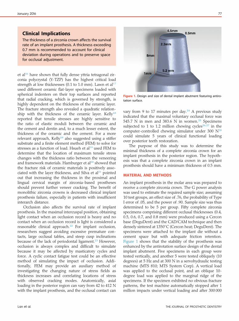
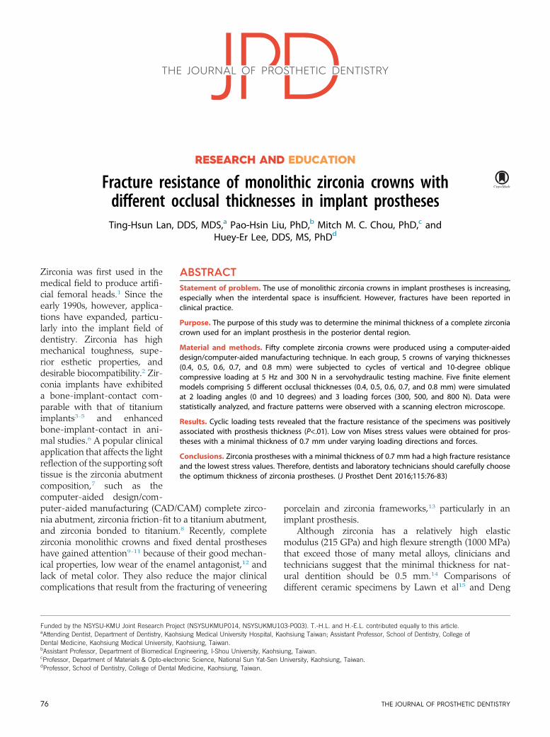
Figure 1. Design and size of dental implant abutment featuring antiro-tation surface.
Clinical ImplicationsThe thickness of a zirconia crown affects the survivalrate of an implant prosthesis. A thickness exceeding0.7 mm is recommended to account for clinicaldeviation during operations and to preserve spacefor occlusal adjustment.
January 2016 77
et al16 have shown that fully dense yttria tetragonal zir-conia polycrystal (Y-TZP) has the highest critical loadstrength at low thicknesses (0.1 to 1.0 mm). Lawn et al17
used different ceramic flat-layer specimens loaded withspherical indenters on their top surfaces and reportedthat radial cracking, which is governed by strength, ishighly dependent on the thickness of the ceramic layer.The fracture strength also revealed a quadratic relation-ship with the thickness of the ceramic layer. Kelly18
reported that tensile stresses are highly sensitive tothe ratio of elastic moduli between the ceramic andthe cement and dentin and, to a much lesser extent, thethickness of the ceramic and the cement. For a morerelevant approach, Kelly18 also suggested using a stiffersubstrate and a finite element method (FEM) to solve forstresses as a function of load. Hsueh et al19 used FEM todetermine that the location of maximum tensile stresschanges with the thickness ratio between the veneeringand framework materials. Hamburger et al20 showed thatthe fracture risk of ceramic materials is positively asso-ciated with the layer thickness, and Silva et al21 pointedout that increasing the thickness in the proximal andlingual cervical margin of zirconia-based prosthesesshould prevent further veneer cracking. The benefit ofmonolithic zirconia crowns is decreased clinical implantprosthesis failure, especially in patients with insufficientinterarch distance.
Occlusion also affects the survival rate of implantprosthesis. In the maximal intercuspal position, obtaininglight contact when an occlusion record is heavy and nocontact when an occlusion record is light is considered areasonable clinical approach.22 For implant occlusion,researchers suggest avoiding excessive premature con-tacts, large occlusal tables, and steep cusp inclinationsbecause of the lack of periodontal ligament.23 However,occlusion is always complex and difficult to simulatebecause it may be affected by masticatory cycles andforce. A cyclic contact fatigue test could be an effectivemethod of simulating the impact of occlusion. Addi-tionally, FEM may provide an auxiliary method ofinvestigating the changing nature of stress fields asthickness increases and correlating locations of stresswith observed cracking modes. Anatomically, axialloading in the posterior region can vary from 42 to 412 Nwith the implant prosthesis, and the occlusal contact can
Lan et al
vary from 9 to 17 minutes per day.24 A previous studyindicated that the maximal voluntary occlusal force was545.7 N in men and 383.6 N in women.25 Specimenssubjected to 1 to 1.2 million chewing cycles26,27 in thecomputer-controlled chewing simulator under 300 N28
could simulate 5 years of clinical functional loadingover posterior teeth restoration.
The purpose of this study was to determine theminimal thickness of a complete zirconia crown for animplant prosthesis in the posterior region. The hypoth-esis was that a complete zirconia crown in an implantprosthesis should have a minimum thickness of 0.5 mm.
MATERIAL AND METHODS
An implant prosthesis in the molar area was prepared toreceive a complete zirconia crown. The G power analysiswas used to estimate the required sample size; assuming10 test groups, an effect size of .76, the probability of TypeI error of .05, and the power of .90. Sample size was thusdetermined to be 5 per group. Fifty complete zirconiaspecimens comprising different occlusal thicknesses (0.4,0.5, 0.6, 0.7, and 0.8 mm) were produced using a Cerconbase (DeguDent) and the CAD/CAM technique and thendensely sintered at 1350�C (Cercon heat; DeguDent). Thespecimens were attached to the implant die without acement space but with adequate friction retention.Figure 1 shows that the stability of the prosthesis wasenhanced by the antirotation surface design of the dentalimplant abutment. Five specimens in each group weretested vertically, and another 5 were tested obliquely (10degrees) at 5 Hz and at 300 N in a servohydraulic testingmachine (MTS 810; MTS System Corp). A vertical loadwas applied to the occlusal point, and an oblique 10-degree load was applied to the marginal ridge of thespecimens. If the specimen exhibited no obvious fracturepatterns, the test machine automatically stopped after 1million impacts under vertical loading and after 300 000
THE JOURNAL OF PROSTHETIC DENTISTRY
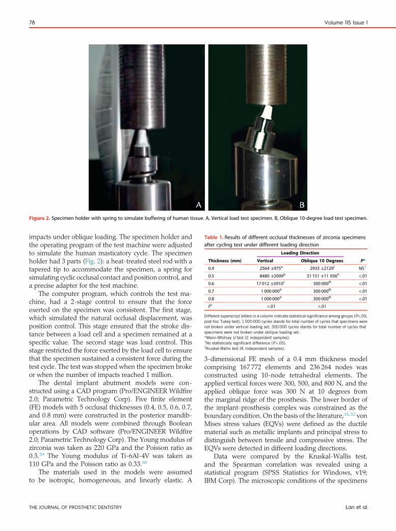
Figure 2. Specimen holder with spring to simulate buffering of human tissue. A, Vertical load test specimen. B, Oblique 10-degree load test specimen.
Table 1. Results of different occlusal thicknesses of zirconia specimensafter cycling test under different loading direction
Thickness (mm)
Loading Direction
P*Vertical Oblique 10 Degrees
0.4 2564 ±975a 2933 ±2129I NS†
0.5 8480 ±2009b 31 151 ±11 936II <.01
0.6 17 012 ±5910c 300 000III <.01
0.7 1 000 000d 300 000III <.01
0.8 1 000 000d 300 000III <.01
P‡ <.01 <.01
Different superscript letters in a column indicate statistical significance among groups (P<.05;post hoc Tukey test); 1 000000 cycles stands for total number of cycles that specimens werenot broken under vertical loading set; 300000 cycles stands for total number of cycles thatspecimens were not broken under oblique loading set.*Mann-Whitney U test (2 independent samples).†No statistically significant difference (P>.05).‡Kruskal-Wallis test (K independent samples).
78 Volume 115 Issue 1
impacts under oblique loading. The specimen holder andthe operating program of the test machine were adjustedto simulate the human masticatory cycle. The specimenholder had 3 parts (Fig. 2): a heat-treated steel rod with atapered tip to accommodate the specimen, a spring forsimulating cyclic occlusal contact and position control, anda precise adapter for the test machine.
The computer program, which controls the test ma-chine, had a 2-stage control to ensure that the forceexerted on the specimen was consistent. The first stage,which simulated the natural occlusal displacement, wasposition control. This stage ensured that the stroke dis-tance between a load cell and a specimen remained at aspecific value. The second stage was load control. Thisstage restricted the force exerted by the load cell to ensurethat the specimen sustained a consistent force during thetest cycle. The test was stopped when the specimen brokeor when the number of impacts reached 1 million.
The dental implant abutment models were con-structed using a CAD program (Pro/ENGINEER Wildfire2.0; Parametric Technology Corp). Five finite element(FE) models with 5 occlusal thicknesses (0.4, 0.5, 0.6, 0.7,and 0.8 mm) were constructed in the posterior mandib-ular area. All models were combined through Booleanoperations by CAD software (Pro/ENGINEER Wildfire2.0; Parametric Technology Corp). The Young modulus ofzirconia was taken as 220 GPa and the Poisson ratio as0.3.29 The Young modulus of Ti-6Al-4V was taken as110 GPa and the Poisson ratio as 0.33.30
The materials used in the models were assumedto be isotropic, homogeneous, and linearly elastic. A
THE JOURNAL OF PROSTHETIC DENTISTRY
3-dimensional FE mesh of a 0.4 mm thickness modelcomprising 167 772 elements and 236 264 nodes wasconstructed using 10-node tetrahedral elements. Theapplied vertical forces were 300, 500, and 800 N, and theapplied oblique force was 300 N at 10 degrees fromthe marginal ridge of the prosthesis. The lower border ofthe implant-prosthesis complex was constrained as theboundary condition. On the basis of the literature,31,32 vonMises stress values (EQVs) were defined as the ductilematerial such as metallic implants and principal stress todistinguish between tensile and compressive stress. TheEQVs were detected in diffeent loading directions.
Data were compared by the Kruskal-Wallis test,and the Spearman correlation was revealed using astatistical program (SPSS Statistics for Windows, v19;IBM Corp). The microscopic conditions of the specimens
Lan et al

Figure 3. Specimens with even thicknesses. A, 0.5 mm. B, 0.6 mm and intact morphology (top) and fractured segments (bottom).
Figure 4. Distributions of stresses in zirconia crowns. (Top) Vertical load of 300 N. (Bottom) Oblique 10-degree load of 300 N on marginal ridge. Fromleft to right are loading models: T 0.4, T 0.5, T 0.6, T 0.7, and T 0.8. T, thickness (mm).
January 2016 79
were observed by scanning electron microscope imaging(JSM-6360; JEOL).
RESULTS
Under vertical loading, the mean number of cycles untilbreakage was 2564, 8480, and 17 012 for 0.4, 0.5, and0.6 mm specimens, respectively (Table 1). The 0.4 and0.5 mm specimens showed obvious breakages thatseparated specimens into 2 or 3 fragments. Specimensthicker than 0.7 mm showed no visible fracture lines orfragments; the test machine was stopped after 1 millionimpacts. Under oblique loading, the mean number ofcycles upon 0.4 and 0.5 mm thick specimens was 2933and 31 151, respectively. Specimens thicker than 0.6 mm
Lan et al
showed no visible fracture lines or fragments; the testmachine was stopped at 300 000 impacts (Fig. 3).
The specimen thickness and the number of cycles hada significant positive association (r=.89). Specimenbreakage was significantly associated with prosthesisthickness (P<.01) (Table 1). Loading directions signifi-cantly differed (P<.01) for all tested thicknesses from0.5 to 0.8 mm, except for 0.4 mm.
Stress concentrated on the corner area of the occlusal-axial wall of the prosthesis when forces were applied indifferent directions. The peak EQV was higher for obliqueloading than for vertical loading (Fig. 4). Comparisons ofdifferent thicknesses under different vertical loadingshowed that a thickness exceeding 0.6 mm had a lowEQV, whereas a thickness of 0.7 mm had the lowest EQV
THE JOURNAL OF PROSTHETIC DENTISTRY
Figure 5. Distributions of stresses in zirconia crowns. (Top) Vertical load of 500 N. (Bottom) Vertical load of 800 N on marginal ridge. From left to rightare loading models: T 0.4, T 0.5, T 0.6, T 0.7, and T 0.8. T, thickness (mm).
0
20
T0.4 T0.5
300 N
T0.6 T0.7 T0.8
Thickness (mm)
40
60
80
EQV
(MPa
)
100 500 N 800 N
Figure 6. Comparison of EQVs in zirconia prosthesis with 5 thicknessesunder vertical loading of 300, 500, and 800 N. Lowest value occurredwhen thickness was 0.7 mm.
EQV
(MPa
)
Thickness (mm)
100
80
60
40
20
T0.4 T0.5 T0.6 T0.7 T0.80
Figure 7. Comparison of EQVs in zirconia prosthesis with 5 thicknessesunder oblique loading of 300 N. Lowest value occurred when thicknesswas 0.8 mm.
80 Volume 115 Issue 1
(Figs. 4-6). Additionally, comparisons of different thick-nesses under oblique loading showed that a thicknessexceeding 0.7 mm had a low EQV, whereas a thickness of0.8 mm had the lowest EQV (Fig. 7).
The scanning electron microscopic images showedbeach marks indicating progressive fatigue failure.Alongside these beach marks, the final fracture zone was
THE JOURNAL OF PROSTHETIC DENTISTRY
typically visible where a brittle failure of the materialoccurred (Fig. 8).
DISCUSSION
Analyses of zirconia specimens show that their thicknessaffects the fracture resistance.15 The present studydemonstrated that the strength of a zirconia specimenincreased with thickness; similar findings have been
Lan et al
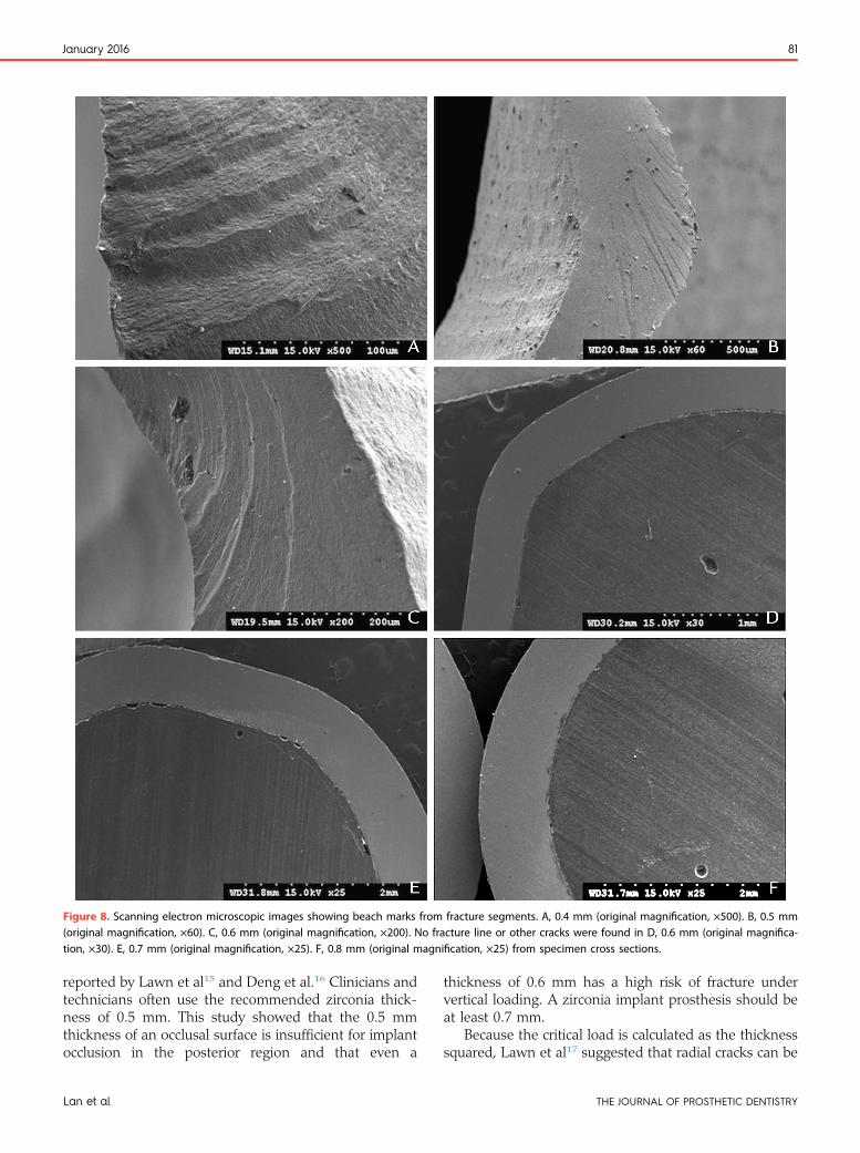
Figure 8. Scanning electron microscopic images showing beach marks from fracture segments. A, 0.4 mm (original magnification, ×500). B, 0.5 mm(original magnification, ×60). C, 0.6 mm (original magnification, ×200). No fracture line or other cracks were found in D, 0.6 mm (original magnifica-tion, ×30). E, 0.7 mm (original magnification, ×25). F, 0.8 mm (original magnification, ×25) from specimen cross sections.
January 2016 81
reported by Lawn et al15 and Deng et al.16 Clinicians andtechnicians often use the recommended zirconia thick-ness of 0.5 mm. This study showed that the 0.5 mmthickness of an occlusal surface is insufficient for implantocclusion in the posterior region and that even a
Lan et al
thickness of 0.6 mm has a high risk of fracture undervertical loading. A zirconia implant prosthesis should beat least 0.7 mm.
Because the critical load is calculated as the thicknesssquared, Lawn et al17 suggested that radial cracks can be
THE JOURNAL OF PROSTHETIC DENTISTRY
82 Volume 115 Issue 1
avoided by using a minimum thickness of 1.5 mm.However, Kelly18 recommended that approaches to morerelevant testing of ceramic restorations should use asubstrate stiffer than epoxy resin in indentation contacttests. Other methods of solving for stresses as a functionof load include FEM or iterative mathematical approxi-mation. In a study by Deng et al,16 comparisons ofdifferent ceramic plates revealed that monolithic zirconiaspecimens had relatively high critical contact loads (800to 900 N) when the thickness exceeded 0.7 mm. How-ever, the substrate was polycarbonate. In the morerelevant method applied in the present study, a heat-treated steel rod was used to simulate the dentalimplant abutment of the cyclic contact test and FEMwhen the stress distribution was analyzed.
The dynamic impact used to fracture the zirconiaprosthesis was set to 300 N to simulate implant occlusionin the mandibular molar area. However, actual clinicalconditions are complex, especially in the case of implantocclusion. The recommended occlusal design includescentered contacts along the implant axis with a flatcentral fossa.22 In occlusal schemes for single implantprosthesis, anterior or lateral guidance is suggested fornatural dentition, light contact is suggested when anocclusal force is heavy, and no contact is suggested whenan occlusal force is light. In most conditions, the implantocclusion is not fully rigid, and the buffer would beprovided by the periodontal ligament of the dentalantagonist and surrounding alveolar bone. When thedental antagonist is an implant prosthesis in the posteriorarea, the buffering effect is lessened and the relative rigidimpact from occlusion is noticeable. This study used aspring to simulate cyclic occlusal contact and positioncontrol to decrease the entirely rigid impact from occlu-sion. Most implant zirconia prosthesis designs shouldhave a minimum thickness of 0.7 mm. However, whenthe occlusal impact is more rigid with less buffering, animplant thickness exceeding 0.7 mm is suggested.
The servohydraulic testing and FE results revealedsimilar trends under vertical loading and oblique loading.Fracture resistance was higher at thicknesses exceeding0.7 mm than at a thickness of 0.5 mm. However, usinga thickness of 0.6 mm is controversial because differentloading types have different effects. For example, MTSloading on a specimen with point contact differs fromFE loading on a specimen with surface contact. Addi-tionally, because of the limitations of the fixture design,the oblique loading force of MTS is less than 300 N, aphenomenon that is attributable to the component offorce (Fig. 2). However, the EQV from 300 N obliqueloading was directly applied to the corners of the speci-mens. The results of the 2 different methods indicate thata thickness of 0.7 mm is recommended for posteriorimplant zirconia prosthesis designs.
THE JOURNAL OF PROSTHETIC DENTISTRY
CONCLUSIONS
Considering the limitations of the study, the followingwere concluded:
1. Cyclic loading tests showed that the fracture resis-tance of the monolithic zirconia prosthesis waspositively associated with thickness.
2. Cyclic loading in a servohydraulic testing machineand persistent loading in FE analysis revealed that azirconia prosthesis with a thickness of 0.7 mm orgreater had the highest fracture resistance and thelowest stress values under vertical and obliqueloading.
3. For clinical use, a zirconia prosthesis with a thick-ness of 0.8 mm is recommended to allow for oper-ative deviation and error in occlusal adjustment.
REFERENCES
1. Piconi C, Maccauro G. Zirconia as a ceramic biomaterial. Biomaterials1999;20:1-25.
2. Manicone PF, Rossi Iommetti P, Raffaelli L. An overview of zirconia ceramics:basic properties and clinical applications. J Dent 2007;35:819-26.
3. Andreiotelli M, Wenz HJ, Kohal RJ. Are ceramic implants a viable alternativeto titanium implants? A systematic literature review. Clin Oral Implants Res2009;20(suppl 4):32-47.
4. Zembic A, Sailer I, Jung RE, Hammerle CH. Randomized-controlled clinicaltrial of customized zirconia and titanium implant abutments for single-toothimplants in canine and posterior regions: 3-year results. Clin Oral ImplantsRes 2009;20:802-8.
5. Koch FP, Weng D, Kramer S, Biesterfeld S, Jahn-Eimermacher A, Wagner W.Osseointegration of one-piece zirconia implants compared with a titaniumimplant of identical design: a histomorphometric study in the dog. Clin OralImplants Res 2010;21:350-6.
6. Park YS, Chung SH, Shon WJ. Peri-implant bone formation and surfacecharacteristics of rough surface zirconia implants manufactured by powderinjection molding technique in rabbit tibiae. Clin Oral Implants Res 2013;24:586-91.
7. van Brakel R, Noordmans HJ, Frenken J, de Roode R, de Wit GC, Cune MS.The effect of zirconia and titanium implant abutments on light reflection ofthe supporting soft tissues. Clin Oral Implants Res 2011;22:1172-8.
8. Kim JS, Raigrodski AJ, Flinn BD, Rubenstein JE, Chung KH, Mancl LA.In vitro assessment of three types of zirconia implant abutments under staticload. J Prosthet Dent 2013;109:255-63.
9. Rojas-Vizcaya F. Full zirconia fixed detachable implant-retained restor-ationsmanufactured from monolithic zirconia: clinical report after two yearsin service. J Prosthodont 2011;20:570-6.
10. Beuer F, Stimmelmayr M, Gueth JF, Edelhoff D, Naumann M. In vitroperformance of full-contour zirconia single crowns. Dent Mater 2012;28:449-56.
11. Park JH, Park S, Lee K, Yun KD, Lim HP. Antagonist wear of three CAD/CAM anatomic contour zirconia ceramics. J Prosthet Dent 2014;111:20-9.
12. Mormann WH, Stawarczyk B, Ender A, Sener B, Attin T, Mehl A. Wearcharacteristics of current aesthetic dental restorative CAD/CAM materials:two-body wear, gloss retention, roughness and martens hardness. J MechBehav Biomed Mater 2013;20:113-25.
13. Schmitter M, Mueller D, Rues S. Chipping behaviour of all-ceramic crownswith zirconia framework and CAD/CAM manufactured veneer. J Dent2012;40:154-62.
14. Denry I, Kelly JR. State of the art of zirconia for dental applications. DentMater 2008;24:299-307.
15. Lawn BR, Deng Y, Thompson VP. Use of contact testing in the character-ization and design of all-ceramic crownlike layer structures: a review.J Prosthet Dent 2001;86:495-510.
16. Deng Y, Lawn BR, Lloyd IK. Characterization of damage modes in dentalceramic bilayer structures. J Biomed Mater Res 2002;63:137-45.
17. Lawn BR, Pajares A, Zhang Y, Deng Y, Polack MA, Lloyd IK, et al. Materialsdesign in the performance of all-ceramic crowns. Biomaterials 2004;25:2885-92.
18. Kelly JR. Clinically relevant approach to failure testing of all-ceramic resto-rations. J Prosthet Dent 1999;81:652-61.
Lan et al
January 2016 83
19. Hsueh CH, Thompson GA, Jadaan OM, Wereszczak AA, Becher PF. Analysisof layer-thickness effects in bilayered dental ceramics subjected to thermalstresses and ring-on-ring tests. Dent Mater 2008;24:9-17.
20. Hamburger JT, Opdam NJM, Bronkhorst EM, Huysmans MC. Indirect res-torations for severe tooth wear: fracture risk and layer thickness. J Dent2014;42:413-8.
21. Silva NRFA, Bonfante EA, Rafferty BT, Zavanelli RA, Rekow ED,Thompson VP, Coelho PG, et al. Modified Y-TZP core design improves all-ceramic crown reliability. J Dent Res 2011;90:104-8.
22. Kim Y, Oh TJ, Misch CE, Wang HL. Occlusal considerations in implanttherapy: clinical guidelines with biomechanical rationale. Clin Oral ImplantsRes 2005;16:26-35.
23. Yuan JC, Sukotjo C. Occlusion for implant-supported fixed dental prosthesesin partially edentulous patients: a literature review and current concepts.J Periodontal Implant Sci 2013;43:51-7.
24. Stanford CM, Brand RA. Toward an understanding of implant occlusion andstrain adaptive bonemodeling and remodeling. J Prosthet Dent 1999;81:553-61.
25. Raadsheer MC, van Eijden TMGJ, van Ginkel FC, Prahl-Andersen B.Contribution of jaw muscle size and craniofacial morphology to human biteforce magnitude. J Dent Res 1999;78:31-42.
26. Kohal RJ, Klaus G, Strub JR. Zirconia-implant-supported all-ceramic crownswithstand long-term load: a pilot investigation. Clin Oral Implants Res2006;17:565-71.
27. Krejci I, Lutz F, Gautschi L. Wear and marginal adaptation of compositionresin inlays. J Prosthet Dent 1994;72:233-44.
28. Eskitascioglu G, Usumez A, Sevimay M, Soykan E, Unsal E. The influence ofocclusal loading location on stresses transferred to implant-supported
Receive Tables of Co
Instructions
To receive tables of contents by e-mail, sign up through our Wodicals/ympr.
Log on and click “Register” in the upper right-hand corner. AAlerts,” then “Add Table of Contents Alert.” Select the categothe search field and click on the Journal title. The title will theprocess, you may add tables of contents alerts by accessing aAlert” link.
You will receive an e-mail message confirming that you have
Note that tables of contents e-mails will be sent when a new
Lan et al
prostheses and supporting bone: a three-dimensional finite element study.J Prosthet Dent 2004;91:144-50.
29. Green DJ, Hannink RH, Swain MV. Transformation toughening of ceramics.Boca Raton: CRC Press; 1989. p. 126-38.
30. Colling EW. The physical metallurgy of titanium alloys. Metals Park: ASMAmerican Society for Metals; 1984. p. 201-9.
31. Huang CC, Lan TH, Lee HE, Wang CH. The biomechanical analysis ofrelative position between implant and alveolar bone: finite element method.J Periodontol 2011;82:489-96.
32. Lan TH, Du JK, Pan CY, Lee HE, Chung WH. Biomechnical analysis ofalveolar bone stress around implants with different thread designs andpitches in the mandibular molar area. Clin Oral Investig 2012;16:363-9.
Corresponding author:Dr Ting-Hsun LanDepartment of Prosthodontics, School of DentistryKaohsiung Medical University100 Shin-Chuan 1st Rd, Kaohsiung 80708TAIWANEmail: [email protected]
AcknowledgmentsThe authors thank the Engineer and Metal Industries Research and DevelopmentCentre for their assistance.
Copyright © 2016 by the Editorial Council for The Journal of Prosthetic Dentistry.
ntents by E-mail
eb site at http://www.journals.elsevierhealth.com/peri-
fter completing the registration process, click on “My ry “Mosby” or type The Journal of Prosthetic Dentistry in n appear, and having already completed the Registration
n issue of the Journal and clicking on the “Add TOC
been added to the mailing list.
issue is posted to the Web site.
THE JOURNAL OF PROSTHETIC DENTISTRY


![The Relationship Between the In Vitro Activity of 3β ... · controlling sebum secretion [9-13]. In order to test this hypoth esis, we compared the activity of .15-3,8-HSD in human](https://static.fdocuments.us/doc/165x107/5e7dd88d64e27756e85a7890/the-relationship-between-the-in-vitro-activity-of-3-controlling-sebum-secretion.jpg)