
Fracture ppt
29
Mixed Mode and Interface Fracture Rui Huang The University of Texas at Austin Spring 2008
description
fracture mechanics
Transcript of Fracture ppt
Mixed Mode and Interface Fracture
Rui HuangThe University of Texas at Austin
Spring 2008

Mixed mode fracture• The stress field near a crack tip may be a mixture of modes I,
II, and III crack-tip field.
• In brittle, isotropic, homogeneous materials, cracks advance in the direction that maintains mode I (opening) at the crack tip.
• In anisotropic materials or interfaces between different materials, cracks may grow under mixed mode conditions.
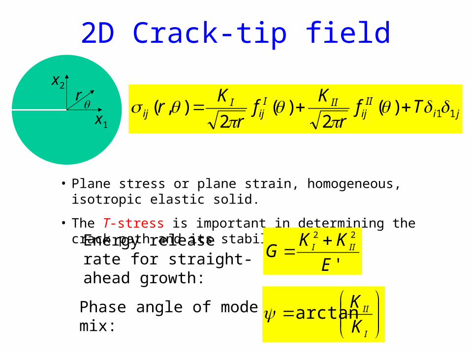
2D Crack-tip field
jiII
ijIII
ijI
ij Tfr
Kf
r
Kr 11)(
2)(
2),(
• Plane stress or plane strain, homogeneous, isotropic elastic solid.
• The T-stress is important in determining the crack path and its stability
x1
x2r
Energy release rate for straight-ahead growth: '
22
E
KKG III
Phase angle of mode mix:
I
II
K
Karctan
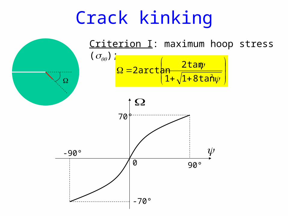
Crack kinkingCriterion I: maximum hoop stress ();
2tan811
tan2arctan2
0-90°
90°
-70°
70°
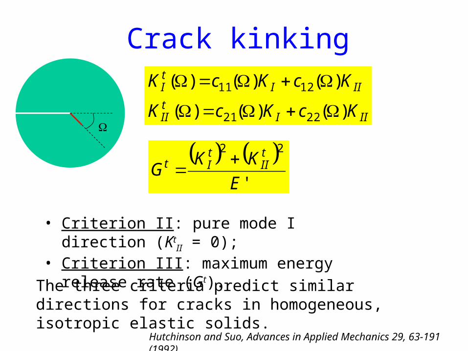
Crack kinking
Hutchinson and Suo, Advances in Applied Mechanics 29, 63-191 (1992).
IIItII
IIItI
KcKcK
KcKcK
)()()(
)()()(
2221
1211
'
22
E
KKG
tII
tIt
• Criterion II: pure mode I direction (KtII = 0);
• Criterion III: maximum energy release rate (Gt).
The three criteria predict similar directions for cracks in homogeneous, isotropic elastic solids.
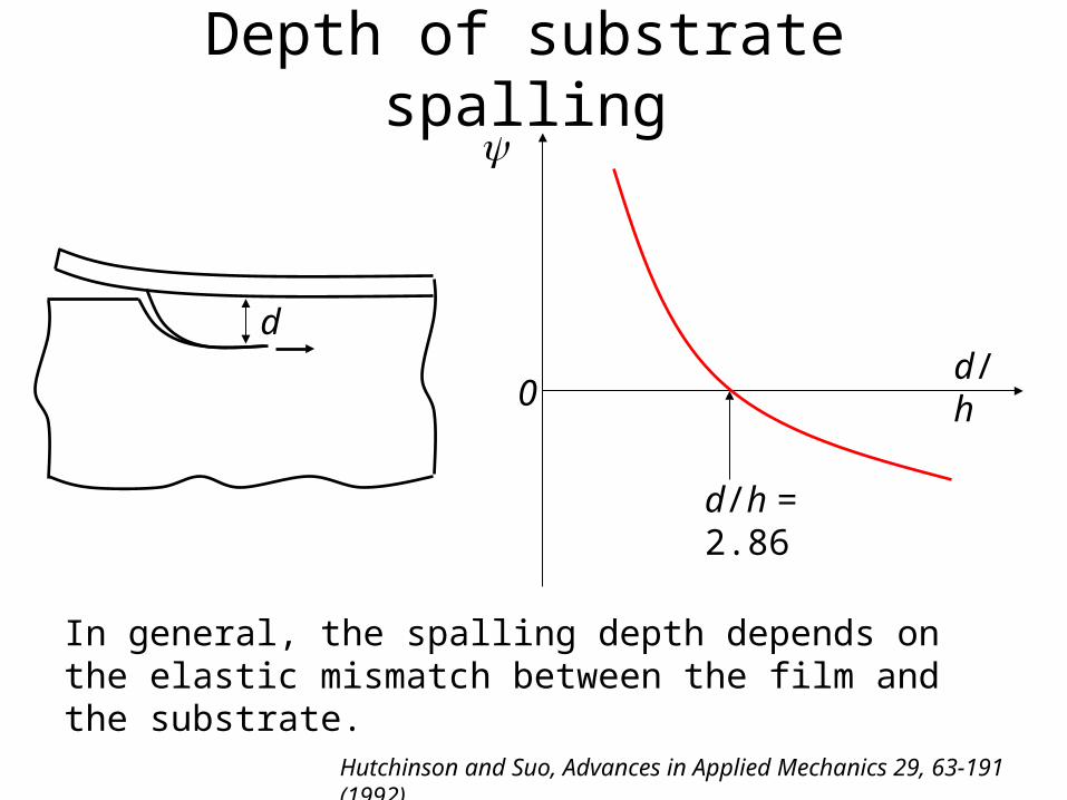
Depth of substrate spalling
dd/h
d/h = 2.86
0
In general, the spalling depth depends on the elastic mismatch between the film and the substrate.
Hutchinson and Suo, Advances in Applied Mechanics 29, 63-191 (1992).

Double cantilever beam
By symmetry, the crack on the mid-plane is in pure mode I and would grow straight ahead.
However, the crack path is unstable. Any slight perturbation to the crack path will cause the crack to deflect further away from the mid-plane.
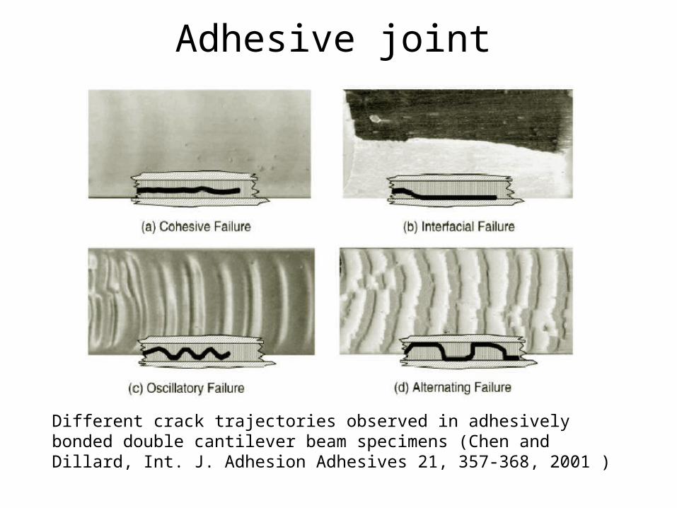
Adhesive joint
Different crack trajectories observed in adhesively bonded double cantilever beam specimens (Chen and Dillard, Int. J. Adhesion Adhesives 21, 357-368, 2001 )
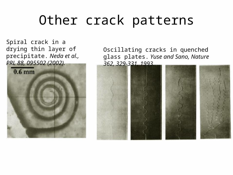
Other crack patterns
Spiral crack in a drying thin layer of precipitate. Neda et al., PRL 88, 095502 (2002).
Oscillating cracks in quenched glass plates. Yuse and Sano, Nature 362, 329-331, 1993.
Fracture of anisotropic materials
• Examples: crystals, fiber-reinforced composites• A crack may grow in a mixed-mode path• Anisotropic fracture toughness, depending on
both the crack growth direction and the mode mix.
• Compare the energy release rate, Gt(Ω), with the fracture toughness, Γ(Ω), to determine crack initiation and kink direction.
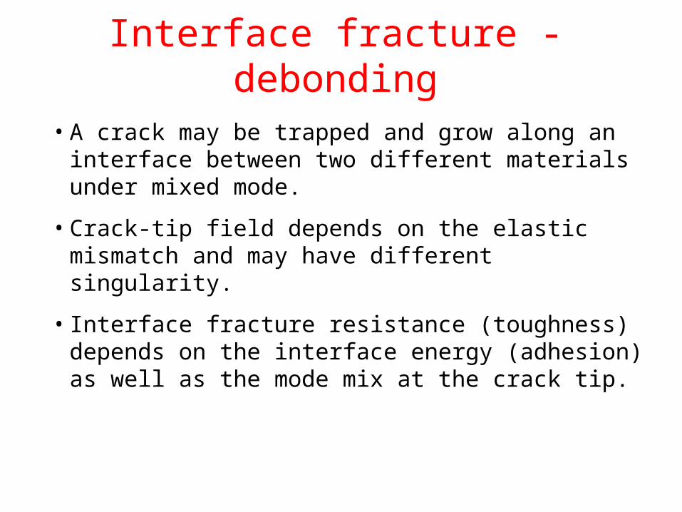
Interface fracture - debonding
• A crack may be trapped and grow along an interface between two different materials under mixed mode.
• Crack-tip field depends on the elastic mismatch and may have different singularity.
• Interface fracture resistance (toughness) depends on the interface energy (adhesion) as well as the mode mix at the crack tip.

Elastic mismatchFor an interface between two elastic materials, the crack behavior depends on the elastic mismatch.
Dundurs parameters:
21
21
1221
1221
11
11
EE
EE
11
11
1221
1221
Plane strain:21
E
E 43
No mismatch: = = 0;
Stiff film on compliant substrate: > 0;
Compliant film on stiff substrate: < 0;
If f = s = 0.5, = 0;
If f = s = 1/3, = /4;
Both and change signs when the materials are switched.
1
-1
-0.25
0.25
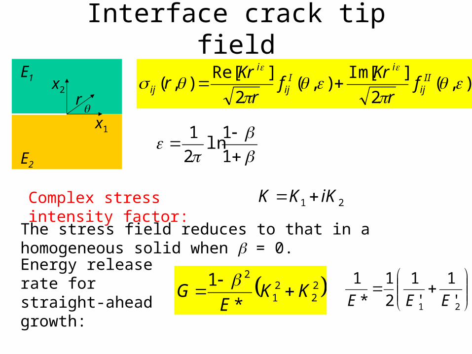
Interface crack tip field
x1
x2r
),(2
]Im[),(
2
]Re[),(
II
ij
iI
ij
i
ij fr
Krf
r
Krr
1
1ln
2
1
Complex stress intensity factor: 21 iKKK
The stress field reduces to that in a homogeneous solid when = 0.
Energy release rate for straight-ahead growth: 2
22
1
2
*
1KK
EG
21 '
1
'
1
2
1
*
1
EEE
E1
E2

Oscillatory singularityTractions ahead of an interface crack tip:
r
riKKi
i
2212122
x1
x2r
When 0, the opening and shearing tractions are coupled; modes I and II are inseparable.
The ratio between the opening and shear tractions varies with r.
Need a length scale to define the mode mix:
]Re[
]Im[arctan
)(
)(arctan
22
21
i
i
Kl
Kl
lr
lr
1
2arctanK
KWhen = 0:
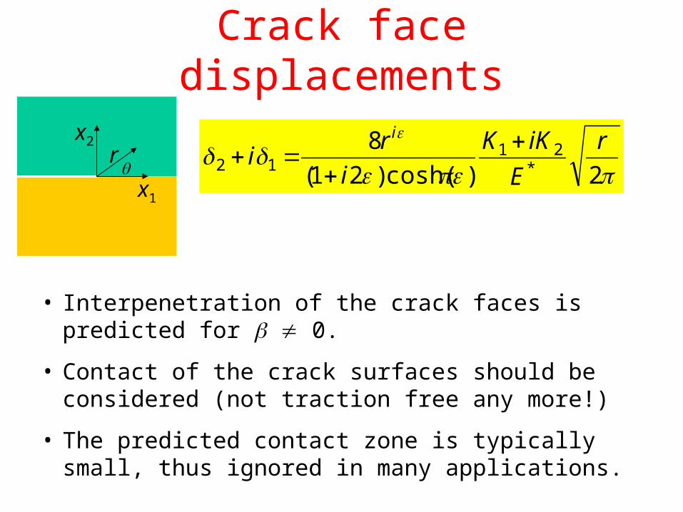
Crack face displacements
2)cosh()21(
8*
2112
r
E
iKK
i
ri
i
x1
x2r
• Interpenetration of the crack faces is predicted for 0.
• Contact of the crack surfaces should be considered (not traction free any more!)
• The predicted contact zone is typically small, thus ignored in many applications.

Example: two semi-infinite blocks22
21 Under the remote loading, at the right crack tip:
2a
ia
aiiiKKK
)2(21212221
Independent of .
Reduce to Griffith’s solution when = 0.
Take l = 2a, then:
2122
2221
2
2tan

Example: double cantilever beam
M
M
h
h
32
),(
21)1(
32
hh
MeiKKK
i
i
Take l = h, then: ),( ),(
0
4/
Hutchinson and Suo, Advances in Applied Mechanics 29, 63-191 (1992).
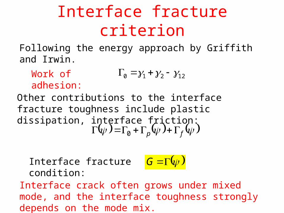
Interface fracture criterion
Following the energy approach by Griffith and Irwin.
Work of adhesion: 12210
Other contributions to the interface fracture toughness include plastic dissipation, interface friction:
fp 0
Interface fracture condition: G
Interface crack often grows under mixed mode, and the interface toughness strongly depends on the mode mix.

Interface fracture toughnessLiechti and Chai (JAM 59, 295-304, 1992).
h
h
UV
hh
eiUcVEiKK
i
i
),(
21
)(*
h
lln),(
cV
Utan
For epoxy/glass interface:
935.0 188.0
060.0 14

Choice of the length scale
(I) Specimen size (thickness, crack length, etc.)
(II) Material (intrinsic) length, e.g., size of plastic zone
Rule of transformation: 1
21122 ln
l
lll
1
1
22 ,ln),( l
l
ll
Using a specimen length renders the toughness dependent on the specimen size, while using an intrinsic material length would avoid such artificial size effect.
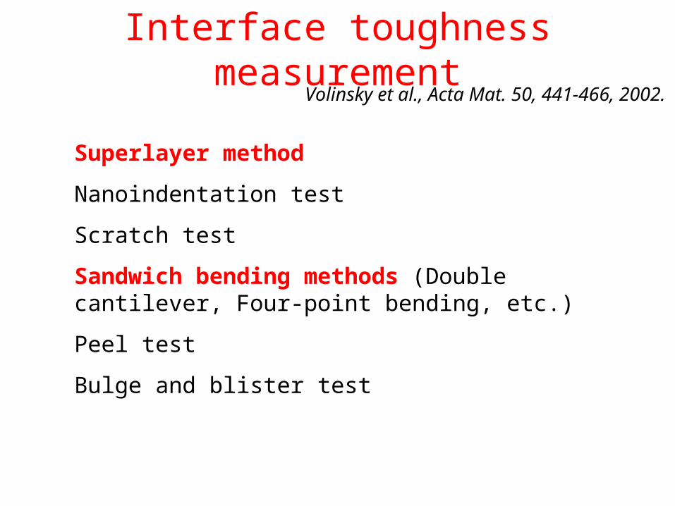
Interface toughness measurementVolinsky et al., Acta Mat. 50, 441-466, 2002.
Superlayer method
Nanoindentation test
Scratch test
Sandwich bending methods (Double cantilever, Four-point bending, etc.)
Peel test
Bulge and blister test

Superlayer test
• Use a superlayer (Cr, epoxy, etc.) to increase the total film thickness and the residual stress without changing the interface.
• Use a thin release layer to introduce an initial debonding.
• Measure the critical thickness to determine the interface toughness.
• Steady-state energy release and the bilayer curvature after debonding
• Phase angle of mode mix?
f
fSS E
hG
2
20
Bagchi et al., J. Mater. Res. 9, 1734-1741, (1994).
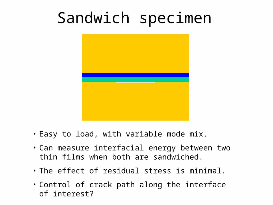
Sandwich specimen
• Easy to load, with variable mode mix.
• Can measure interfacial energy between two thin films when both are sandwiched.
• The effect of residual stress is minimal.
• Control of crack path along the interface of interest?
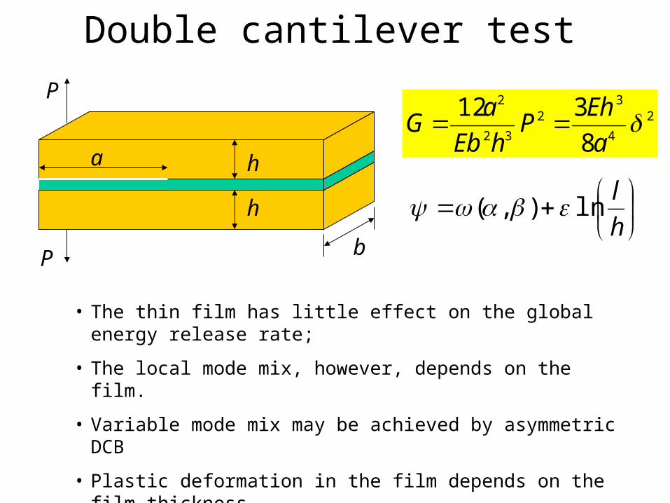
Double cantilever test
h
h
P
P
a
b
2
4
32
32
2
8
312 a
EhP
hEb
aG
h
lln),(
• The thin film has little effect on the global energy release rate;
• The local mode mix, however, depends on the film.
• Variable mode mix may be achieved by asymmetric DCB
• Plastic deformation in the film depends on the film thickness
• Various crack paths are possible (in-layer, oscillatory, or alternating)

Four-point bend test
h
h
PP
PPL L
2
32
2
4
21P
hEb
LGSS
h
lln),(41
• No need to monitor crack length
• Mode mix can be varied by asymmetric bending
P
Steady state
Charalambides et al, 1989; Cao and Evans; 1989; Ma, 1997; Dauskardt et al., 1998.
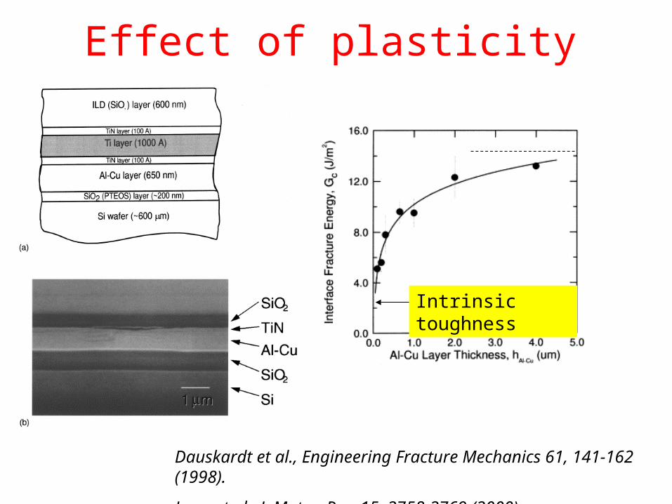
Effect of plasticity
Dauskardt et al., Engineering Fracture Mechanics 61, 141-162 (1998).
Lane et al., J. Mater. Res. 15, 2758-2769 (2000).
Intrinsic toughness

Other effects on interface fracture
• Interface roughness: increased surface area, asperity contact and friction
• Interface chemistry: segregation, bond density• Environment: moisture, stress corrosion or subcritical
debonding
Lane, Annual Rev. Mat. Res. 33, 29-54 (2003).

Summary
• Under mixed-mode fracture, a crack in a homogeneous, isotropic elastic solid kinks into mode-I path; only mode-I fracture toughness is needed.
• Along an interface, a debonding crack often grows under mixed mode, with oscillatory singularity; interface toughness depends on the mode mix.
• Various methods are available for interface toughness measurement; the effects of plasticity, interface roughness, chemistry, and environment must be carefully considered.

Additional readings
Freund and Suresh: Chapter 4;
Suo, Reliability of Interconnect Structures. In Comprehensive Structural Integrity (Milne, Ritchie, Karihaloo, Editors-in-Chief), Volume 8: Interfacial and Nanoscale Failure (Gerberich and Yang, Editors), Elsevier, 2003.
Hutchinson and Suo, Advances in Applied Mechanics 29, 63-191 (1992);
Rice, J. Appl. Mech. 55, 98-103 (1988).