
Fatigue Life Calculation of Welded Joints Based on Fracture Mechanics

University of Liège
Aerospace & Mechanical Engineering
Fracture Mechanics, Damage and Fatigue
Safe-Life Design
Ludovic Noels
Computational & Multiscale Mechanics of Materials – CM3
http://www.ltas-cm3.ulg.ac.be/
Chemin des Chevreuils 1, B4000 Liège
Fracture Mechanics – Safe Life Design

Introduction to safe-life design
• Design with stresses lower than
– Elastic limit (sp0) or
– Tensile strength (sTS0)
• ~1860 : Wöhler
– Technologist in the German railroad system
– Studied the failure of railcar axles
• After various times in service
• At loads considerably lower than expected
• Failure due to cyclic loading/unloading
w/2 w/2
w/2 w/2 t
s
1 cycle =
2 reversals
2013-2014 Fracture Mechanics – Safe Life Design 2

Introduction to safe-life design
• Empirical approach
– Life of a structure depends on
• Minimal & maximal stresses: smin & smax & mean stress: sm=(smax + smin)/2
• Amplitude: sa = Ds/2 = (smax - smin)/2
• Plastic increment Dep
• Load Ratio: R = smin / smax
– See lecture on crack propagation
• Under particular environmental conditions (humidity, high temperature, …):
– Frequency of cycle
– Shape of cycle (sine, step, …)
t
smax
smin
Ds = smax-smin
sa = Ds/2
sm
1 cycle =
2 reversals e
s
Dep
Ds
De
sm
creep
2013-2014 Fracture Mechanics – Safe Life Design 3

Introduction to safe-life design
• Safe-life design
– No crack before a determined number of cycles: life of the structure
• At the end of the expected life the component
is changed even if no failure has occurred
• Emphasis on prevention of crack initiation
• Approach theoretical in nature
– Assumes initial crack free structures
– Components of rotating structures vibrating
with the flow cycles (blades)
• Once cracks form, the remaining life is very
short due to the high frequency of loading
2013-2014 Fracture Mechanics – Safe Life Design 4

Introduction to safe-life design
• How to estimate the time-life?
– Based on empirical approaches
• Macroscopic material responses
(fatigue tests …)
• Does not directly compute the
microstructure evolution
– Requires
• Accurate knowledge of
response fields
– Stress
– Stress concentration
» Factor Kt
– Plastic strain
– Temperature
• Accounting for non-linear
material behavior
• Use of security factor
– As low as possible
2013-2014 Fracture Mechanics – Safe Life Design 5

Introduction to safe-life design
• Inaccurate estimation of plastic strain
– Low-cycle fatigue of a blade from
stage 1 of the high-pressure turbine
– Cracking at stress concentration in
the internal cooling passages
– Blade failed and impacted
other blades, which separated
from platform
Source: Australian Transport Safety, Engine Failure, Boeing Co 717-200, VH-VQA, Near Melbourne, Victoria, Report
– Final, http://www.atsb.gov.au/publications/investigation_reports/2004/aair/aair200402948.aspx
2013-2014 Fracture Mechanics – Safe Life Design 6

Material behavior
• Balance of body B – Momenta balance
• Linear
• Angular
– Boundary conditions • Neumann
• Dirichlet
• Small deformations with linear elastic, homogeneous & isotropic material
– (Small) Strain tensor , or
– Hooke’s law , or
with
– Inverse law
with
b
T
n
2m l = K - 2m/3
2013-2014 Fracture Mechanics – Safe Life Design 7

• Elasto-plasticity (small deformations)
– Beyond a threshold the material experiences irreversible deformations
– Typical behavior at low temperature
• Curves s-e independent of time
• Examples
– INCONEL 718 (up to 600°C)
– IN 100 (up to 750°C)
• Applications
– Compressor of turbo-engines
– Yield surface
f < 0: elastic region
f = 0: plasticity
– Plastic flow
• Assumption: deformations can be added
• Normal plastic flow
– Path dependency (incremental equations in d )
Material behavior
(True)
e
(Tru
e)
s
sTS
sp0
ep ee
E
2013-2014 Fracture Mechanics – Safe Life Design 8

• Dislocation motion (see previous lecture)
– Metallic bonds
• FCC or BCC above DBTT
– A dislocation is characterized by
• The Burger vector
• Dislocation line
(line along which the distortion is the largest)
• Slip plane
(plane where the dislocation motion occurs)
Material behavior: Elasto-plasticity at low T°
© DoITPoMS, University of Cambridge
Dislocation
line
Burger
vector b
b
b
2013-2014 Fracture Mechanics – Safe Life Design 9

• Hardening laws
Material behavior: Elasto-plasticity at low T°
Isotr
opic
Hard
enin
g
Kin
em
atic H
ard
enin
g
Tension-compression
s11
3 s12
f(s, X)=0
X
Tension-torsion
s11
3 s12
f(s, e p)=0
e
s
sp0
e p ee
E
-sp0
sp(ep)
-sp(ep)
e
s
sp0
e p e e
sp0
sp0 X(e p)
sp0
2013-2014 Fracture Mechanics – Safe Life Design 10

• Phenomenological explanations
– Isotropic hardening
• Dislocations creation due to plastic deformations
– Irregularities at the grain boundaries
(Poly-crystalline material)
– Irregular crystal surface
(mono-crystalline material)
• Increase of the dislocation density
• Obstruct dislocations motion
– Long range elastic force between dislocations of same sign
• Macroscopic yield stress increases
Material behavior: Elasto-plasticity at low T°
e
s
sp0
e p e e
E
-sp0
sp(e p)
-sp(e p)
2013-2014 Fracture Mechanics – Safe Life Design 11

• Phenomenological explanations (2)
– Kinematic hardening
• Polycrystalline metals
• 2 possible sources
– Dislocations accumulate (pile-up) at barriers
(grain boundaries, precipitations)
» They can move easily in backward direction
» Yield is reduced in reverse direction
– When strains are reversed, dislocation
sources produce dislocations of opposite sign
» Annihilation of dislocations
» Reduce the strength (as yield is proportional to dislocation density)
Material behavior: Elasto-plasticity at low T°
e
s
sp0
e p e e
sp0
sp0 X(e p)
sp0
2013-2014 Fracture Mechanics – Safe Life Design 12

• Von Mises isotropic hardening (J2-plasticity)
– Yield surface
f < 0: elastic region
f = 0: plasticity
• Deviatoric stress
– Plastic flow • Assumption: deformations can be added
• Normal plastic flow
• Normality: since
• Then the plastic flow becomes
Material behavior: Elasto-plasticity at low T°
e
s
sp0
ep ee
E
-sp0
sp(ep)
-sp(ep)
2013-2014 Fracture Mechanics – Safe Life Design 13

• Von Mises isotropic hardening (2)
– Yield surface
f < 0: elastic region
f = 0: plasticity
– Plastic flow
•
• During plastic flow the representative stress state remains on the yield surface
– Free energy
• Can be defined as with
Material behavior: Elasto-plasticity at low T°
Hardening law
f(s, e p+de p)=0
f<0
s*
ds*
f(s*,e p)=0
df=0
sp
s2
s3
s1
2013-2014 Fracture Mechanics – Safe Life Design 14

• Von Mises kinematic hardening
– Yield surface
f < 0: elastic region
f = 0: plasticity
• Deviatoric part of the stress tensor
• X is deviatoric by nature
• A new yield surface is defined
– Example: plastic flow during tensile test
Material behavior: Elasto-plasticity at low T°
e
s
sp0
e p e e
sp0
sp0 X(e p)
sp0
2013-2014 Fracture Mechanics – Safe Life Design 15

• Von Mises kinematic hardening (2)
– Yield surface
– Plastic flow
• Assumption: deformations can be added
• Normal plastic flow
• Normality: since
• We also have
Material behavior: Elasto-plasticity at low T°
e
s
sp0
ep ee
sp0
sp0 X(ep)
sp0
2013-2014 Fracture Mechanics – Safe Life Design 16

• Von Mises kinematic hardening (3)
– Yield surface
•
– Plastic flow (2)
•
•
• As X is a stress, an associated strain is defined in the free energy function
with
• During plastic flow the representative stress state remains on the yield surface
– What is missing is the law governing the evolution of X: hardening law
Material behavior: Elasto-plasticity at low T°
f(s, a+da)=0
f<0 s*
ds*
f(s*, a)=0
df=0 sp
0 dX
sp0
X
s2
s3
s1
2013-2014 Fracture Mechanics – Safe Life Design 17

• Von Mises kinematic hardening (4)
– Prager linear hardening flow
• At any time, in 1D: s = X(e p) ± sp0
Material behavior: Elasto-plasticity at low T°
f<0
sp0
X
s2
s3
s1
e
s
sp0
e p e e
sp0
sp0 X(e p)
sp0
2013-2014 Fracture Mechanics – Safe Life Design 18

• Von Mises kinematic hardening (5)
– Armstrong-Frederick non linear hardening law
•
• 1D monotonic tensile test
• At any time, in 1D: s = X(e p) ± sp0
Material behavior: Elasto-plasticity at low T°
s2
s3
s1
f<0
sp0
Limit surface
X e
s
sp0
ep ee
sp0
X(ep) C/g
Hardening Dynamic recovery
2013-2014 Fracture Mechanics – Safe
Life Design 19

• General formulation
– Recourse to N internal variables Vk
– Yield surface
f < 0: elasticity
f = 0: plastic flow
– Plastic flow
• The representative stress state
remains on yield surface
– Particular cases
Material behavior: Elasto-plasticity at low T°
f(s, Vk+dVk)=0
f<0 s*
ds*
f(s*, Vk)=0
df=0
s2
s3
s1
Internal
variable
Associated
stress
Isotropic hardening e p sp
Kinematic hardening a X
2013-2014 Fracture Mechanics – Safe Life Design 20

• Example: Combination of isotropic and kinematic hardening
– Yield surface
– Free energy function
•
– Plastic flow
•
Material behavior: Elasto-plasticity at low T°
s2
s3
s1
f<0
sp0
X
sp
2013-2014 Fracture Mechanics – Safe Life Design 21

• Example: Combination of isotropic and kinematic hardening (2)
–
– From yield surface, during plastic flow
• &
• During plastic flow the representative stress
state remains on yield surface
– Hardening laws
• Isotropic
• Kinematic
Material behavior: Elasto-plasticity at low T°
s2
s3
s1
f<0
sp0
X
sp
2013-2014 Fracture Mechanics – Safe Life Design 22

• Bauschinger effect
– Due to kinematic hardening
– Cyclic loading
Material behavior: Elasto-plasticity at low T°
e
s
sp0
e p
Linear kinematic
hardening model
Experiment
t
s
1 cycle =
2 reversals
Ds
e
s
De p
De
sm
2013-2014 Fracture Mechanics – Safe Life Design 23

• Fatigue hardening/softening
– The Hysteretic loop is not always
directly stabilized
– Result from changes in material structures
• Intensity of changes decreases
with cycles number
– The material can exhibit
• Fatigue hardening
• Fatigue softening
Material behavior: Elasto-plasticity at low T°
e
s
Dep
Ds
De
sm
2013-2014 Fracture Mechanics – Safe Life Design 24

• Fatigue hardening/softening with accommodation
Material behavior: Elasto-plasticity at low T° C
ontr
olle
d D
e =
cst
Cyclic softening Cyclic hardening
Contr
olle
d D
s =
cst
s
t e
s
De
2013-2014 Fracture Mechanics – Safe Life Design 25
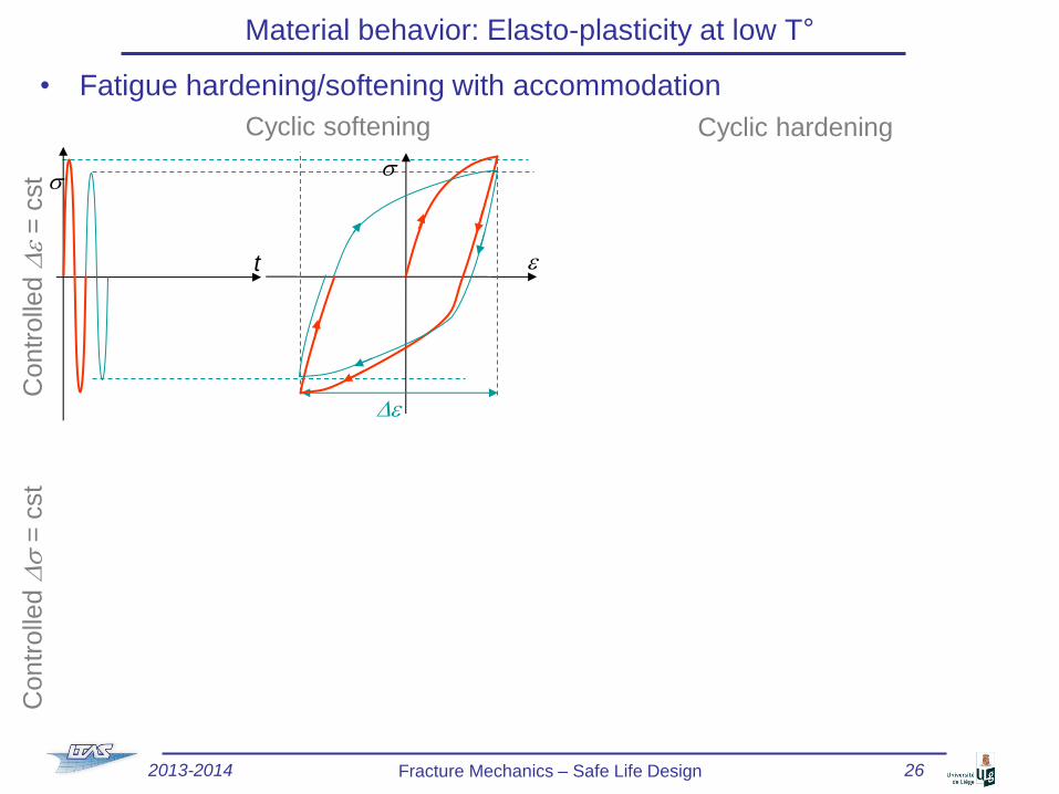
• Fatigue hardening/softening with accommodation
Material behavior: Elasto-plasticity at low T° C
ontr
olle
d D
e =
cst
Cyclic softening Cyclic hardening
s
t e
s
De
Contr
olle
d D
s =
cst
2013-2014 Fracture Mechanics – Safe Life Design 26

• Fatigue hardening/softening with accommodation
Material behavior: Elasto-plasticity at low T° C
ontr
olle
d D
e =
cst
Cyclic softening Cyclic hardening
t
s
e
s
De p*
De
Contr
olle
d D
s =
cst
2013-2014 Fracture Mechanics – Safe Life Design 27

• Fatigue hardening/softening with accommodation
Material behavior: Elasto-plasticity at low T° C
ontr
olle
d D
e =
cst
Cyclic softening Cyclic hardening
t
s
e
s
De p*
De
t
s
s
e
De
Contr
olle
d D
s =
cst
2013-2014 Fracture Mechanics – Safe Life Design 28

• Fatigue hardening/softening with accommodation
Material behavior: Elasto-plasticity at low T° C
ontr
olle
d D
e =
cst
Cyclic softening Cyclic hardening
t
s
e
s
De p*
De
s
t
s
e
De
Contr
olle
d D
s =
cst
2013-2014 Fracture Mechanics – Safe Life Design 29
• Fatigue hardening/softening with accommodation
Material behavior: Elasto-plasticity at low T° C
ontr
olle
d D
e =
cst
Cyclic softening Cyclic hardening
t
s
e
s
De p*
De
t
s
s
e
De p*
De
Contr
olle
d D
s =
cst
2013-2014 Fracture Mechanics – Safe Life Design 30

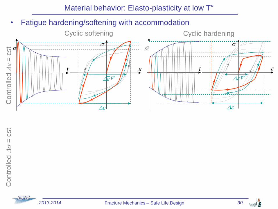
• Fatigue hardening/softening with accommodation
Material behavior: Elasto-plasticity at low T° C
ontr
olle
d D
e =
cst
Cyclic softening Cyclic hardening
t
s
e
s
De p*
De
t
s
s
e
De p*
De
Contr
olle
d D
s =
cst s
e t
s Ds
2013-2014 Fracture Mechanics – Safe Life Design 31

• Fatigue hardening/softening with accommodation
Material behavior: Elasto-plasticity at low T° C
ontr
olle
d D
e =
cst
Cyclic softening Cyclic hardening
t
s
e
s
De p*
De
t
s
s
e
De p*
De
Contr
olle
d D
s =
cst
e t
s
s Ds
2013-2014 Fracture Mechanics – Safe Life Design 32

• Fatigue hardening/softening with accommodation
Material behavior: Elasto-plasticity at low T° C
ontr
olle
d D
e =
cst
Cyclic softening Cyclic hardening
t
s
e
s
De p*
De
t
s
s
e
De p*
De
Contr
olle
d D
s =
cst
e t
s
s
De p*
Ds
2013-2014 Fracture Mechanics – Safe Life Design 33

• Fatigue hardening/softening with accommodation
Material behavior: Elasto-plasticity at low T° C
ontr
olle
d D
e =
cst
Cyclic softening Cyclic hardening
t
s
e
s
De p*
De
t
s
s
e
De p*
De
Contr
olle
d D
s =
cst
e t
s
s
De p*
Ds
t
s
s
e
Ds
2013-2014 Fracture Mechanics – Safe Life Design 34

• Fatigue hardening/softening with accommodation
Material behavior: Elasto-plasticity at low T° C
ontr
olle
d D
e =
cst
Cyclic softening Cyclic hardening
t
s
e
s
De p*
De
t
s
s
e
De p*
De
Contr
olle
d D
s =
cst
e t
s
s
De p*
Ds
t
s
s
e
Ds
2013-2014 Fracture Mechanics – Safe Life Design 35

• Fatigue hardening/softening with accommodation
Material behavior: Elasto-plasticity at low T° C
ontr
olle
d D
e =
cst
Cyclic softening Cyclic hardening
t
s
e
s
De p*
De
t
s
s
e
De p*
De
Contr
olle
d D
s =
cst
e t
s
s
De p*
Ds
t
s
s
e
De p*
Ds
2013-2014 Fracture Mechanics – Safe Life Design 36
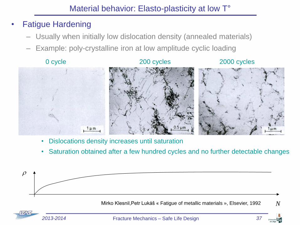
• Fatigue Hardening
– Usually when initially low dislocation density (annealed materials)
– Example: poly-crystalline iron at low amplitude cyclic loading
• Dislocations density increases until saturation
• Saturation obtained after a few hundred cycles and no further detectable changes
Material behavior: Elasto-plasticity at low T°
0 cycle 200 cycles 2000 cycles
Mirko Klesnil,Petr Lukáš « Fatigue of metallic materials », Elsevier, 1992 N
r
2013-2014 Fracture Mechanics – Safe Life Design 37

• Fatigue softening
– Usually when initially high dislocation density (cold worked materials)
– Example: poly-crystalline iron at high amplitude cyclic loading
• Dislocations localize to form cells (hardening process)
• If increase of amplitude (at constant D deformation)
– Cells break down to form persistent slip bands (PSB)
– Localization of slips in PSB
– Softening
– Origin of cracks
Material behavior: Elasto-plasticity at low T°
1 cycle 100 cycles 1000 cycles
2013-2014 Fracture Mechanics – Safe Life Design 38

• Fatigue softening (2)
– High amplitude cyclic loading
Material behavior: Elasto-plasticity at low T°
Cyclically Hardened
material
PSB
Cyclic Hardening
Cyclic Softening
N
Ds/2 De p/2 =1%
De p/2 =0.5%
De p/2 =0.25%
De p/2 =0.03%
1 10 100 1000 10000
2013-2014 Fracture Mechanics – Safe Life Design 39

• Combination of structural and cyclic loading
Primary loading Secondary loading
– Examples
• Pressure vessels
• Gas turbines
– Where Ds can be due to
» Flow fluctuation
» Dilatation stress
– Stabilized state?
Material behavior: Elasto-plasticity at low T°
t
s
sm
t
s
Ds
2013-2014 Fracture Mechanics – Safe Life Design 40

• Combination of structural and cyclic loading under controlled s
– Elastic adaptation
• For reduced Ds
• Isotropic or/and
linear kinematic
hardening
• Adaptation in 1 cycle
• For slightly higher Ds
• Isotropic and (linear)
kinematic hardening
• Adaptation after
a few cycles
Material behavior: Elasto-plasticity at low T°
t
s
Ds
sm
s
e
sp0
2sp
2013-2014 Fracture Mechanics – Safe Life Design 41

• Combination of structural and cyclic loading under controlled s
– Elastic adaptation
• For reduced Ds
• Isotropic or/and
linear kinematic
hardening
• Adaptation in 1 cycle
• For slightly higher Ds
• Isotropic and (linear)
kinematic hardening
• Adaptation after
a few cycles
Material behavior: Elasto-plasticity at low T°
t
s
Ds
sm
s
e
sp0
2sp
2013-2014 Fracture Mechanics – Safe Life Design 42

• Combination of structural and cyclic loading under controlled s
– Elastic adaptation
• For reduced Ds
• Isotropic or/and
linear kinematic
hardening
• Adaptation in 1 cycle
• For slightly higher Ds
• Isotropic and (linear)
kinematic hardening
• Adaptation after
a few cycles
Material behavior: Elasto-plasticity at low T°
t
s
Ds
sm
s
e
sp0
2sp
2013-2014 Fracture Mechanics – Safe Life Design 43

• Combination of structural and cyclic loading under controlled s
– Elastic adaptation
• For reduced Ds
• Isotropic or/and
linear kinematic
hardening
• Adaptation in 1 cycle
• For slightly higher Ds
• Isotropic and (linear)
kinematic hardening
• Adaptation after
a few cycles
Material behavior: Elasto-plasticity at low T°
t
s
Ds
sm
s
e
sp0
2sp
2013-2014 Fracture Mechanics – Safe Life Design 44
• Combination of structural and cyclic loading under controlled s
– Elastic adaptation
• For reduced Ds
• Isotropic or/and
linear kinematic
hardening
• Adaptation in 1 cycle
• For slightly higher Ds
• Isotropic and (linear)
kinematic hardening
• Adaptation after
a few cycles
Material behavior: Elasto-plasticity at low T°
t
s
Ds
sm
s
e
sp0
2sp
t
s s
Ds
sm
e
sp0
2sp1>2sp
0
X1
1 1
sp1
2013-2014 Fracture Mechanics – Safe Life Design 45

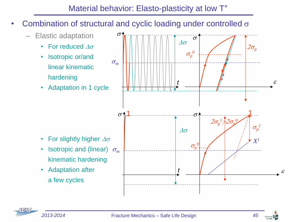
• Combination of structural and cyclic loading under controlled s
– Elastic adaptation
• For reduced Ds
• Isotropic or/and
linear kinematic
hardening
• Adaptation in 1 cycle
• For slightly higher Ds
• Isotropic and (linear)
kinematic hardening
• Adaptation after
a few cycles
Material behavior: Elasto-plasticity at low T°
t
s
Ds
sm
s
e
sp0
2sp
t
s s
Ds
sm
e
sp0
2sp1>2sp
0
1 1
1’
X1’
X1
2013-2014 Fracture Mechanics – Safe Life Design 46

• Combination of structural and cyclic loading under controlled s
– Elastic adaptation
• For reduced Ds
• Isotropic or/and
linear kinematic
hardening
• Adaptation in 1 cycle
• For slightly higher Ds
• Isotropic and (linear)
kinematic hardening
• Adaptation after
a few cycles
Material behavior: Elasto-plasticity at low T°
t
s
Ds
sm
s
e
sp0
2sp
t
s s
Ds
sm
e
sp0
2sp1>2sp
0
1 2sp
2>2sp1
2 2 1
X2
2013-2014 Fracture Mechanics – Safe Life Design 47

• Combination of structural and cyclic loading under controlled s
– Elastic adaptation
• For reduced Ds
• Isotropic or/and
linear kinematic
hardening
• Adaptation in 1 cycle
• For slightly higher Ds
• Isotropic and (linear)
kinematic hardening
• Adaptation after
a few cycles
Material behavior: Elasto-plasticity at low T°
t
s
Ds
sm
s
e
sp0
2sp
t
s s
Ds
sm
e
sp0
2sp1>2sp
0
1 2sp
2>2sp1
2 2 1
2’
X2’ X2
2013-2014 Fracture Mechanics – Safe Life Design 48

• Combination of structural and cyclic loading under controlled s
– Elastic adaptation
• For reduced Ds
• Isotropic or/and
linear kinematic
hardening
• Adaptation in 1 cycle
• For slightly higher Ds
• Isotropic and (linear)
kinematic hardening
• Adaptation after
a few cycles
Material behavior: Elasto-plasticity at low T°
t
s
Ds
sm
s
e
sp0
2sp
t
s s
Ds
sm
e
sp0
XN
spN
spN
2013-2014 Fracture Mechanics – Safe Life Design 49

• Combination of structural and cyclic loading under controlled s (2)
– Accommodation
• Large Ds
• Can be modeled
by linear kinematic
hardening
(accommodation after
1 cycle)
Material behavior: Elasto-plasticity at low T°
t
s s
Ds
sm
e
sp0 X1
1
s
Ds
sm
ep
sp0
sp0
X1
2013-2014 Fracture Mechanics – Safe Life Design 50

• Combination of structural and cyclic loading under controlled s (2)
– Accommodation
• Large Ds
• Can be modeled
by linear kinematic
hardening
(accommodation after
1 cycle)
Material behavior: Elasto-plasticity at low T°
t
s s
Ds
sm
e
sp0
2sp0
1
1’
X1’
X1
sp0
s
Ds
sm
ep
sp0
2sp0
X1
X1’
2013-2014 Fracture Mechanics – Safe Life Design 51

• Combination of structural and cyclic loading under controlled s (2)
– Accommodation
• Large Ds
• Can be modeled
by linear kinematic
hardening
(accommodation after
1 cycle)
Material behavior: Elasto-plasticity at low T°
t
s s
Ds
sm
e
sp0
2sp0
2 1
1’
X2
X1’ 2sp0
s
Ds
sm
ep
sp0
2sp0
X2
X1’
2013-2014 Fracture Mechanics – Safe Life Design 52

• Combination of structural and cyclic loading under controlled s (2)
– Accommodation
• Large Ds
• Can be modeled
by linear kinematic
hardening
(accommodation after
1 cycle)
Material behavior: Elasto-plasticity at low T°
t
s s
Ds
sm
e
sp0
2sp0
2
2’
1
1’
X2
X2’
s
Ds
sm
ep
sp0
2sp0
X2
X2’
2013-2014 Fracture Mechanics – Safe Life Design 53

• Combination of structural and cyclic loading under controlled s (2)
– Accommodation
• Large Ds
• Can be modeled
by linear kinematic
hardening
(accommodation after
1 cycle)
Material behavior: Elasto-plasticity at low T°
Dep*
t
s s
Ds
sm
e
sp0
2sp0
X Max
X min
s
Dep*
Ds
sm
ep
sp0
2sp0
X Max
X min
2013-2014 Fracture Mechanics – Safe Life Design 54

• Combination of structural and cyclic loading under controlled s (3)
– Ratcheting (or Rochet)
• Large Ds & sm ≠ 0
• Threatens life
• Non-linear kinematic
hardening leads to
ratcheting
If |X|min ≠ |X|Max
curves of back-stress
are not reversible
Material behavior: Elasto-plasticity at low T°
s
ep
sp0
sp0
sm
X1
t
s s
Ds
sm e
sp0
sp0
1
X1
2013-2014 Fracture Mechanics – Safe Life Design 55

• Combination of structural and cyclic loading under controlled s (3)
– Ratcheting (or Rochet)
• Large Ds & sm ≠ 0
• Threatens life
• Non-linear kinematic
hardening leads to
ratcheting
If |X|min ≠ |X|Max
curves of back-stress
are not reversible
Material behavior: Elasto-plasticity at low T°
s
ep
sp0
sp0
sp0
sm
X1
X1’
t
s s
Ds
sm e
sp0
sp0
1
1’
X1’
sp0
X1
2013-2014 Fracture Mechanics – Safe Life Design 56

• Combination of structural and cyclic loading under controlled s (3)
– Ratcheting (or Rochet)
• Large Ds & sm ≠ 0
• Threatens life
• Non-linear kinematic
hardening leads to
ratcheting
If |X|min ≠ |X|max
curves of back-stress
are not reversible
Material behavior: Elasto-plasticity at low T°
s
ep
sp0
sp0
sp0
sm
X2
X1’
dep
t
s s
Ds
sm e
sp0
sp0
sp0
sp0
dep
1 2
1’
X1’
X2
2013-2014 Fracture Mechanics – Safe Life Design 57

• Combination of structural and cyclic loading under controlled s (3)
– Ratcheting (or Rochet)
• Large Ds & sm ≠ 0
• Threatens life
• Non-linear kinematic
hardening leads to
ratcheting
If |X|min ≠ |X|max
curves of back-stress
are not reversible
Material behavior: Elasto-plasticity at low T°
s
ep
sp0
sp0
sp0
sp0
sm
X2
X2’
dep
t
s s
Ds
sm e
sp0
sp0
sp0
sp0
dep
1 2
1’ 2’
X2’
X2
2013-2014 Fracture Mechanics – Safe Life Design 58

• Combination of structural and cyclic loading under controlled s (3)
– Ratcheting (or Rochet)
• Large Ds & sm ≠ 0
• Threatens life
• Non-linear kinematic
hardening leads to
ratcheting
If |X|min ≠ |X|max
curves of back-stress
are not reversible
Material behavior: Elasto-plasticity at low T°
dep
t
s s
Ds
sm e
sp0
sp0
sp0
sp0
dep
s
ep
sp0
sp0
sp0
sp0
sm
X Max
X min
2013-2014 Fracture Mechanics – Safe Life Design 59

• Combination of structural and cyclic loading under controlled s (4)
– Bree diagram
• For a given material
• As
– Non-linear kinematic hardening
always predicts ratcheting
(if sm ≠ 0)
– Linear kinematic hardening
never predicts ratcheting
• Laws should be enhanced
– Threshold
– Chaboche (1991)
Material behavior: Elasto-plasticity at low T°
Ds/2sp0
sm/sp0
1
1
2
2013-2014 Fracture Mechanics – Safe Life Design 60

• Combination of structural and cyclic loading under controlled e
No mean stress relaxation Mean stress relaxation
(Accommodation) (Ratcheting)
Material behavior: Elasto-plasticity at low T°
t
e
De
De p*
s
sm
e
sp0
2sp0
t
e
De
De p*
s
s1m
e
sp0
2sp0
s2m
sNm
2013-2014 Fracture Mechanics – Safe Life Design 61

• Creep
– Example: IN100 & T = 1000°C under different constant tensile stresses
– Primary creep
• Low strain (e < e1)
• Initially high but decreases
with hardening
Material behavior: Thermal effect
4 –
3 –
2 –
1 –
137 MPa
e p (%)
171 MPa
205 MPa
239 MPa x fracture
0 10 100 t (heures) tR
eRp
e1
e2
e p .
e p .
s cst
s cst
2013-2014 Fracture Mechanics – Safe Life Design 62

• Creep
– Example: IN100 & T = 1000°C under different constant tensile stresses
– Primary creep
• Low strain (e < e1)
• Initially high but decreases
with hardening
– Secondary creep
• For e1 < e < e2
• Near constant
• Balance between hardening
and thermal softening
• Dislocation slip & climb
(see next slide)
Material behavior: Thermal effect
4 –
3 –
2 –
1 –
137 MPa
e p (%)
171 MPa
205 MPa
239 MPa x fracture
0 10 100 t (heures) tR
eRp
e1
e2
e p .
e p .
e p .
s cst
s cst
2013-2014 Fracture Mechanics – Safe Life Design 63

• Creep
– Example: IN100 & T = 1000°C under different constant tensile stresses
– Primary creep
• Low strain (e < e1)
• Initially high but decreases
with hardening
– Secondary creep
• For e1 < e < e2
• Near constant
• Balance between hardening
and thermal softening
• Dislocation slip & climb
(see next slide)
– Tertiary creep
• For e > e2
• Increases of
• Begin of damage
– Grain-boundary sliding
– Voids formation
Material behavior: Thermal effect
4 –
3 –
2 –
1 –
137 MPa
e p (%)
171 MPa
205 MPa
239 MPa x fracture
0 10 100 t (heures) tR
eRp
e1
e2
e p .
e p .
e p .
e p .
s cst
s cst
2013-2014 Fracture Mechanics – Safe Life Design 64

Material behavior: Thermal effect
• Dislocation slip and climb
– During primary creep
• Dislocations accumulate (pile-up) at barriers (grain boundaries, precipitations)
– During secondary creeps
• If atoms
– Have enough energy
(Temperature and strain energy)
– In close packed lattice
They will self-diffuse and fill vacancies
• This corresponds for a blocked dislocation
– To climb normal to its slip plane by atoms self-diffusion
– To lies on an unobstructed slip plane
– To move and to annihilate with a dislocation of opposite sign
Self diffusion
Slip
plane
2013-2014 Fracture Mechanics – Safe Life Design 65

Material behavior: Thermal effect
• Tertiary creep
– Grain boundary sliding is activated
– Formation of voids under shearing
Nimonic 80A, 1023 K and 154 MPa
2013-2014 Fracture Mechanics – Safe Life Design 66

Material behavior: Thermal effect
• Recovery: strain driven test
– Quenched AU4G alloy
– At 200 °C
300
200
100
0 20 40 60 80 100 120 140 160
s (Mpa)
t (s)
e cst
e cst
2013-2014 Fracture Mechanics – Safe Life Design 67

Material behavior: Thermal effect
• Secondary creep
– Constant
– Norton law
•
– Lemaître law
•
e p .
IN 100 INCO 800
20
10
0 500 1000
T (°C)
n (Norton)
30
20
10
700 800 900 1000 1100
3000
2000
1000
T (°C)
n
m
n
m
K
K (MPa.s1/n)
2013-2014 Fracture Mechanics – Safe Life Design 68

Material behavior: Thermal effect
• Effect of creep during cyclic loading under constant Ds
– IN 100 Super alloy, first cycle with holding time, 900°C
• Creep depends on
– Holding time
– Temperature
– Frequency
t
s (Mpa)
Ds
ep
400
s (Mpa)
400
0.1 -0.1
creep
2013-2014 Fracture Mechanics – Safe Life Design 69

Material behavior: Thermal effect
• Example of creep during cyclic loading under constant Ds
– HP turbine blade
• Long working phases at high temperature (axial loading)
• Long rest phases at room T°
• Inter-crystalline fracture mode and voids
t
s
2013-2014 Fracture Mechanics – Safe Life Design 70

Material behavior: Thermal effect
• Effect of creep during cyclic loading under constant De
– IN 100 Super alloy, first cycle with holding time, 900°C
• Relaxation depends on
– Holding time
– Temperature
– Frequency
– Creep and relaxation can be modeled by considering
• Kinematic hardening
• Visco-plasticity
e
t
Ds
ep
s
0.1 -0.1
Relaxation: decrease of ee
2013-2014 Fracture Mechanics – Safe Life Design 71

Material behavior: Thermal effect
• Model of creep during cyclic loading
– Stabilized cycle
• During holding time
• increases (so sp)
• decreases (so sv)
• a increases
– Model requires
• (Isotropic) Kinematic hardening
• Visco-plasticity
– Lemaître & Chaboche
• Use a dissipation potential
ep
ep .
ep
s
sp(ep)
sv(ep) .
sp(ep)
. sv(e
p)
X
If <0, there should not be a plastic flow If ●>0: <●> = ●, if not <●> =0
2013-2014 Fracture Mechanics – Safe Life Design 72

Material behavior: Thermal effect
• Visco-plasticity model
– Plastic flow direction & amplitude?
• Normality
– Let
– As
W*>0
s
W=0
sv dX
sp
X
s2
s3
s1
∂W/∂s
2013-2014 Fracture Mechanics – Safe Life Design 73
Material behavior: Thermal effect
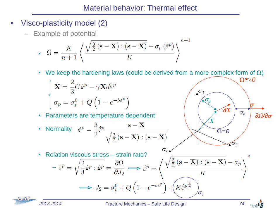
• Visco-plasticity model (2)
– Example of potential
•
• We keep the hardening laws (could be derived from a more complex form of W)
• Parameters are temperature dependent
• Normality
• Relation viscous stress – strain rate?
–
W*>0
s
W=0
sv dX
sp
X
s2
s3
s1
∂W/∂s
2013-2014 Fracture Mechanics – Safe Life Design 74
sv

Introduction to damage
• Failure mechanism of ductile material
– Plastic deformations prior to (macroscopic)
failure of the specimen
• Dislocations motion void nucleation
around inclusions micro cavity
coalescence crack growth
• Griffith criterion should
be replaced by
True e
Tru
e s
sTS
sp0
2013-2014 Fracture Mechanics – Safe Life Design 75

Introduction to damage
• Failure mechanism of fatigue
– Crack nucleation at persistent slip bands
– Stage I crack growth
• Along slip planes
– Stage II crack growth
• Across several grains
– Along a slip plane in each grain,
– Straight ahead macroscopically
• Striation of the failure surface:
corresponds to the cycles
Perfect crystal
Fra
ctu
re
mechanic
s
2013-2014 Fracture Mechanics – Safe Life Design 76

Introduction to damage
• Failure mechanism of creep
– Inter-granular void formation
2013-2014 Fracture Mechanics – Safe Life Design 77

Introduction to damage
• Interaction between damage sources
• Safe-life design: evaluation of a resulting damage
CREEP
FATIGUE DUCTILITY
DAMAGE
interaction
High temperature; visco-plastic deformation;
inter-granular voids
Large plastic deformations;
low temperature;
voids nucleation and growth
Bauschinger effect,
crack growth
2013-2014 Fracture Mechanics – Safe Life Design 78
Introduction to damage
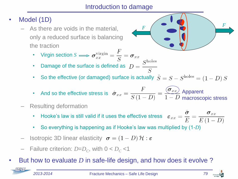
• Model (1D)
– As there are voids in the material,
only a reduced surface is balancing
the traction
• Virgin section S
• Damage of the surface is defined as
• So the effective (or damaged) surface is actually
• And so the effective stress is
– Resulting deformation
• Hooke’s law is still valid if it uses the effective stress
• So everything is happening as if Hooke’s law was multiplied by (1-D)
– Isotropic 3D linear elasticity
– Failure criterion: D=DC, with 0 < DC <1
• But how to evaluate D in safe-life design, and how does it evolve ?
F F
Apparent
macroscopic stress
2013-2014 Fracture Mechanics – Safe Life Design 79

Total life approach
• Empirical approach: Total life
– Life of a structure depends on
• Minimal & maximal stresses: smin & smax & mean stress: sm=(smax + smin)/2
• Amplitude: sa = Ds/2 = (smax - smin)/2
• Plastic increment Dep
• Load Ratio: R = smin / smax
– See lecture on crack propagation
• Under particular environmental conditions (humidity, high temperature, …):
– Frequency of cycle
– Shape of cycle (sine, step, …)
t
smax
smin
Ds = smax-smin
sa = Ds/2
sm
1 cycle =
2 reversals e
s
Dep
Ds
De
sm
creep
2013-2014 Fracture Mechanics – Safe Life Design 80

Total life approach
• First kind of total life approach: « stress life » approach
– For high cycle fatigue
• Structures experiencing (essentially) elastic deformations
• Life > 104 cycles
– Fatigue limit
• For sa < se (endurance limit):
infinite life (>107 cycles)
• For sa > se, finite life
• Materials with fatigue limit
– Mild/low strength steel
– Ti-Al-Mg alloys
– With se ~ [ 0.35 ; 0.5] sTS
• Materials without fatigue limit
– Al alloys
– Mg alloys
– High strength steels
– Non-ferro alloys
Nf
se
sa = Ds/2
103 104 105 106 107
2013-2014 Fracture Mechanics – Safe Life Design 81

Total life approach
• First kind of total life approach: « stress life » approach (2)
– Life of structure
• Assumptions
– sm = 0 &
– Nf identical cycles before failure
• For sa < se (endurance limit):
infinite life (>107 cycles)
• For sa > se, finite life
• With se ~ [ 0.35 ; 0.5 ] sTS
• 1910, Basquin Law
– sf’ fatigue coefficient (mild steel Tamb : ~ [1; 3] GPa)
– b fatigue exponent (mild steel Tamb : ~ [-0.1; -0.06])
– Parameters resulting from experimental tests
– If endurance limit exists: use Nf=107 and sa = se in Basquin Law
Nf
se
sa = Ds/2
103 104 105 106 107
2013-2014 Fracture Mechanics – Safe Life Design 82

Total life approach
• First kind of total life approach: « stress life » approach (3)
– Effect of mean stress
• Wöhler curves
• For sm ≠ 0 and Nf identical cycles, the maximal amplitude is corrected
– Soderberg conservative
– Goodman
– Gerber only for alloys under tension
R = 0
R = -0.5
R = -1
R = 0.2 R = 0
R = -0.5
R = -1
smax (ksi)
120 -
80 -
40 -
20 -
10 10 2 10 3 10 4 10 5 NF
A 517
A 201
sTS
2013-2014 Fracture Mechanics – Safe Life Design 83

Total life approach
• First kind of total life approach: « stress life » approach (4)
– Effect of varying amplitude loads
• ni cycles of constant amplitude lead to a damage
• 1945, Miner-Palmgreen law
– At fracture:
– Does not account for the sequence in which the cycles are applied
– Only if low variation in cycles
– Only if pure fatigue damage
t
sa1,
sm1
n1 n2
sa2, sm2
s
Nf
sa (sm=0)
103 104 105 106 107
Nf1 Nf2
sa2(sm=0)
sa1(sm=0)
2013-2014 Fracture Mechanics – Safe Life Design 84

Total life approach
• Second kind of total life approach: « strain life » approach
– For low cycle fatigue
• Structures experiencing (essentially)
– Large plastic deformations
– Stress concentration
– (High temperatures)
– For Nf identical cycles before failure
• 1954, Manson-Coffin
– ef’ : fatigue ductility coefficient ~ true fracture ductility (metals)
– c : fatigue ductility coefficient exponent ~ [-0.7 , -0.5] (metals)
– plastic strain increment during the loading cycles
e
s
Dep
Ds
De
sm
2013-2014 Fracture Mechanics – Safe Life Design 85

Total life approach
• General relation
Using Goodman
De
/2 (
log
scale
)
2Nf (log scale)
1
c
1 b
LCF HCF
2013-2014 Fracture Mechanics – Safe Life Design 86

Introduction to damage approach
• Experiments
• Damage (in 1D)
– Fatigue
– Ductility
– Creep (Kachanov-Rabotnov)
Material, temperature dependent,
parameters obtained from 1D
experiments
2013-2014 Fracture Mechanics – Safe Life Design 87
0.5 1
1
D
FN N
Experimental test Damaged
sample
s
s
Equivalent
homogenized sample
0 1D

Introduction to damage approach
• Advantage
– Write
• Dissipation potential W and
• Free energy
in terms of the effective stress instead of the micro-stress s
– Non-linear interaction of damages from different natures
• Example: Creep and fatigue
2013-2014 Fracture Mechanics – Safe Life Design 88

Design using total life approach
• 1952, De Havilland 106 Comet 1, UK (1)
– First jetliner, 36 passengers, pressurized cabin
• 1954, January, flight BOAC 781 Rome-Heathrow
– Plane G-ALYP disintegrated above the sea
– After 1300 flights
– Total life approach failed
• Fuselages failed well before the design limit of 10000 cycles
2013-2014 Fracture Mechanics – Safe Life Design 89

• 1952, De Havilland 106 Comet 1, UK (2) – 1954, August, retrieve from the see of the
ALYP roof • Origin of failure at the communication window
• Use of square riveted windows
• Punched riveting instead of drill riveting
Presence of initial defects
• The total life approach accounts for crack initiation in smooth specimen
but does not account for inherent defects
– The initial defects of the fuselage tested against fatigue could have
hardened after the initial static test load, which was not the case with the
production planes
– Life time can be improved by
• “Shot-peening” : surface bombarded by small spherical media
– Residual stresses of compression in the surface layer
– Prevents crack initiation
• Surface polishing (to remove cracks)
Design using total life approach
2013-2014 Fracture Mechanics – Safe Life Design 90

• Economically inefficient
– PW F100 (F15 & F16)
– Using total life approach against LCF
• All disks replaced when statistically
1 disk had a fatigue crack (a<0.75 mm)
• Studies indicate that at least 80%
of parts replaced have at least a
full order of magnitude of remaining
fatigue life
• Extra cost for US Air force: > $50 000 000 /year
Design using total life approach
http://www.grc.nasa.gov/WWW/RT/RT1996/5000/5220bo1.htm
http://ocw.mit.edu/courses/materials-science-and-engineering/3-35-fracture-and-fatigue-fall-2003/lecture-notes/fatigue_crack_growth.pdf
(Subra Suresh)
2013-2014 Fracture Mechanics – Safe Life Design 91

• Economically inefficient (2)
– Air-force starts using Retirement For Cause approach in 1986
• Periodic nondestructive evaluation to assess the damage state of components
• Components with no detectable cracks: returned to service
– Allows
• Parts with low life
– Detected and discarded before they can cause an incident
• Parts with high life
– Used to their full potential
– Basic to an RFC program
• Calculation of crack-growth rates
under the expected service loads
(mechanical and thermal)
• The results are used to define
safe-use intervals between
required (nondestructive) inspections
Design using total life approach
http://www.grc.nasa.gov/WWW/RT/RT1996/5000/5220bo1.htm
http://ocw.mit.edu/courses/materials-science-and-engineering/3-35-fracture-and-fatigue-fall-2003/lecture-notes/fatigue_crack_growth.pdf
(Subra Suresh)
2013-2014 Fracture Mechanics – Safe Life Design 92

Fatigue design
• « Damage tolerant design »
– Assume cracks are present from the beginning of service
– Characterize the significance of fatigue cracks on structural performance
• Control initial crack sizes through
manufacturing processes and
(non-destructive) inspections
• Estimate crack growth rates during
service (Paris-Erdogan) & plan
conservative inspection intervals
(e.g. every so many years, number
of flights)
• Verify crack growth during
these inspections
• Predict end of life (af)
• Remove old structures from service
before predicted end-of-life (fracture) or
implement repair-rehabilitation strategy
– Non-destructive inspections
• Optical
• X-rays
• Ultrasonic (reflection on crack surface)
P
P
a
a (
cm)
Nf (105) 1 2 3 4 5 6 7
5
4
3
2
DP1
DP2 > DP1
Structure inspection
possible (for DP1) Rapid
crack
growth
Rupture
2013-2014 Fracture Mechanics – Safe Life Design 93

Exercice 1
• Effect of average stress
– Circular rod
• Uniform cross-sectional A = 20 cm2
• Subjected to a mean axial force of 120 kN
– Material
• Fatigue strength sa = sfs = 250 MPa at 106 cycles of fully reversed loading
• Tensile strength sTS = 500 MPa
• Yield stress sp = 350 MPa
– Allowable amplitude of force P for which the shaft would be designed to
withstand at least one million fatigue cycles?
P
120 kN
2013-2014 Fracture Mechanics – Safe Life Design 94

Exercice 2
• Shot-peened metallic material
– Properties before shot-peening
• Young modus E = 210 GPa
• HCF parameters s’f = 1100 MPa, b = -0.08
• LCF parameters e’f = 1, c = -0.63
– Due to shot-peening
• Compressive residual stress of 250 MPa
• Tensile strength sTS = 500 Mpa
– What is the life improvement due
to shoot-peening?
2013-2014 Fracture Mechanics – Safe Life Design 95

References
• References – Mechanics of Solid Materials. Jean Lemaître,Jean-Louis Chaboche,
Cambridge University press, 1994
– Plasticity and viscoplasticity under cyclic loadings. Jean-Louis Chaboche,
ATHENS – Course MP06 – 16 – 20 March 2009
2013-2014 Fracture Mechanics – Safe Life Design 96

Exercice 1
• Circular rod
– Due to P, there is a cyclic loading
of amplitude sa
• Without axial force
– The rod can stand 106 cycles at sa(sm=0) = 250 MPa
• With axial force
– Average stress sm = 120000 / 0.002 = 60 MPa
– For 106 cycles, the loading P should induce a cyclic loading of amplitude
• Soderberg
• Goodman
• Gerber
(Ok as tension)
P
120 kN
2013-2014 Fracture Mechanics – Safe Life Design 97

Exercice 2
• Before shot peening
–
• After shot peening
– Residual stress acts like a compressive mean stress
2013-2014 Fracture Mechanics – Safe Life Design 98

Exercice 2
• Comparison
– Improve mainly the HCF regime
2013-2014 Fracture Mechanics – Safe Life Design 99
100
105
10-4
10-3
10-2
10-1
100
Nf
De/2
OriginalWith shot-peening
Nf
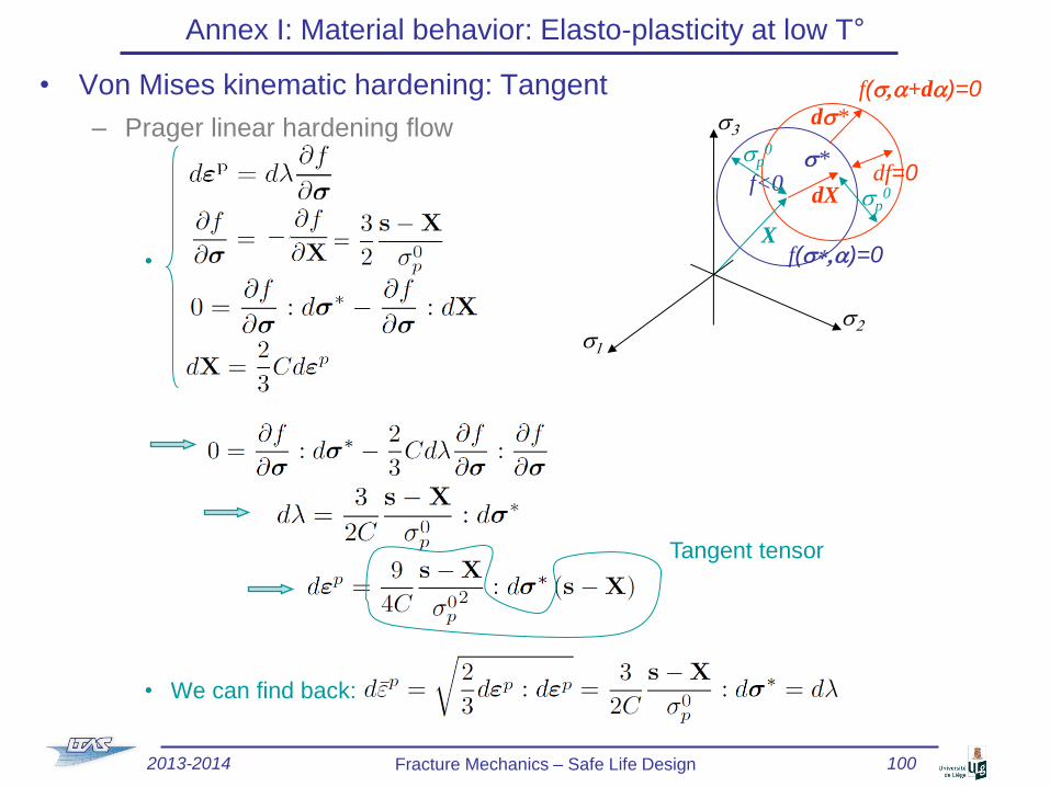
• Von Mises kinematic hardening: Tangent
– Prager linear hardening flow
•
• We can find back:
Annex I: Material behavior: Elasto-plasticity at low T°
f(s,a+da)=0
f<0 s*
ds*
f(s*,a)=0
df=0 sp
0 dX
sp0
X
s2
s3
s1
Tangent tensor
2013-2014 Fracture Mechanics – Safe Life Design 100

• Von Mises kinematic hardening: Tangent (2)
– Armstrong-Frederick non linear hardening law
•
Annex I: Material behavior: Elasto-plasticity at low T°
f(s,a+da)=0
f<0 s*
ds*
f(s*,a)=0
df=0 sp
0 dX
sp0
X
s2
s3
s1
2013-2014 Fracture Mechanics – Safe Life Design 101


![ADVANCES IN FATIGUE AND FRACTURE MECHANICS · PDF fileADVANCES IN FATIGUE AND FRACTURE MECHANICS ANALYSES FOR AIRCRAFT ... process and to use the advanced analysis tools ... 8], ANSYS](https://static.fdocuments.us/doc/165x107/5aab414a7f8b9a8f498bacce/advances-in-fatigue-and-fracture-mechanics-in-fatigue-and-fracture-mechanics.jpg)