FRACTOGRAPHY OF POLYMER COMPOSITES: … OF POLYMER COMPOSITES: CURRENT STATUS AND FUTURE ISSUES E....
15
FRACTOGRAPHY OF POLYMER COMPOSITES: CURRENT STATUS AND FUTURE ISSUES E. S. Greenhalgh 1 and M. J. Hiley 2 1 The Composites Centre, Imperial College, London, UK, SW7 2AZ 2 Applied Materials, QinetiQ, Farnborough, Hants, UK, GU14 0LX [email protected] ABSTRACT There has been considerable progress in the development of characterisation methods and predictive tools in composite engineering. However, these need to keep pace with the rapid advancement of these materials, such as new processing routes, architectures, constituent types, and applications and drivers for design. Fractographic analysis, the examination of fracture surfaces to deduce information, underpins material development and provides an insight into the physical processes by which composites are damaged and fail. This paper presents the current status of composite fractography, showing that the techniques are well developed, and thus permit the interpretation of most structural failures. However, this paper also highlights the areas in which further research is required, such as linking fracture morphologies to semi-qualitative parameters relating to the loading history and conditions at failure. The influence of factors such as environment and cyclic loading still need to be addressed. Furthermore, as composite architectures move towards increased use of through-thickness reinforcement, there is a need to develop techniques by which such materials can be analysed. However, fractography has proved to be powerful and reliable tool for the composite engineer, and is a vital technique for the overall development of composite structures. 1. INTRODUCTION The development of structural materials tends to focus on three important properties; Young’s Modulus (E), Strength (σ c ) and Toughness (G C ). To give designers the confidence to use a material, it is important that the influence of factors such as environment, processing, loading conditions and initial damage state on these properties are measured and understood. Knowledge of these means a material can be modelled and thus structural behaviour can be predicted. Consequently, a material technology is deemed to be mature if these three parameters are fully characterised. Numerical and analytical models of materials and structures have now reached an unprecedented level of accuracy and sophistication, such that engineers have a formidable suite of tools at their disposal to develop innovative and efficient structural designs. However, the tools for polymer composites are less mature. Furthermore, their development is striving to keep pace with rapid advancements in composite materials, such as new processing routes, architectures, constituent types, and applications and drivers for design. Therefore, it is perhaps informative to consider the current understanding of stiffness, strength and toughness of polymer composite materials. Stiffness: Young’s Modulus dictates the response of the material to mechanical loading, including buckling, dynamic and cyclic/vibration behaviour. With polymer composites, this property is primarily dictated by the properties of the constituents; simplified but reliable models exist which can predict composite stiffness. There is also a good understanding of how this parameter is controlled by factors such as volume fraction. In addition, models exist which can predict the influence of in-service factors such as temperature and moisture on stiffness. Therefore, in applications which are response or
Transcript of FRACTOGRAPHY OF POLYMER COMPOSITES: … OF POLYMER COMPOSITES: CURRENT STATUS AND FUTURE ISSUES E....
FRACTOGRAPHY OF POLYMER COMPOSITES: CURRENT STATUS AND FUTURE ISSUES
E. S. Greenhalgh1 and M. J. Hiley2
1 The Composites Centre, Imperial College, London, UK, SW7 2AZ 2 Applied Materials, QinetiQ, Farnborough, Hants, UK, GU14 0LX
ABSTRACT There has been considerable progress in the development of characterisation methods and predictive tools in composite engineering. However, these need to keep pace with the rapid advancement of these materials, such as new processing routes, architectures, constituent types, and applications and drivers for design. Fractographic analysis, the examination of fracture surfaces to deduce information, underpins material development and provides an insight into the physical processes by which composites are damaged and fail. This paper presents the current status of composite fractography, showing that the techniques are well developed, and thus permit the interpretation of most structural failures. However, this paper also highlights the areas in which further research is required, such as linking fracture morphologies to semi-qualitative parameters relating to the loading history and conditions at failure. The influence of factors such as environment and cyclic loading still need to be addressed. Furthermore, as composite architectures move towards increased use of through-thickness reinforcement, there is a need to develop techniques by which such materials can be analysed. However, fractography has proved to be powerful and reliable tool for the composite engineer, and is a vital technique for the overall development of composite structures.
1. INTRODUCTION The development of structural materials tends to focus on three important properties; Young’s Modulus (E), Strength (σc) and Toughness (GC). To give designers the confidence to use a material, it is important that the influence of factors such as environment, processing, loading conditions and initial damage state on these properties are measured and understood. Knowledge of these means a material can be modelled and thus structural behaviour can be predicted. Consequently, a material technology is deemed to be mature if these three parameters are fully characterised.
Numerical and analytical models of materials and structures have now reached an unprecedented level of accuracy and sophistication, such that engineers have a formidable suite of tools at their disposal to develop innovative and efficient structural designs. However, the tools for polymer composites are less mature. Furthermore, their development is striving to keep pace with rapid advancements in composite materials, such as new processing routes, architectures, constituent types, and applications and drivers for design. Therefore, it is perhaps informative to consider the current understanding of stiffness, strength and toughness of polymer composite materials.
Stiffness: Young’s Modulus dictates the response of the material to mechanical loading, including buckling, dynamic and cyclic/vibration behaviour. With polymer composites, this property is primarily dictated by the properties of the constituents; simplified but reliable models exist which can predict composite stiffness. There is also a good understanding of how this parameter is controlled by factors such as volume fraction. In addition, models exist which can predict the influence of in-service factors such as temperature and moisture on stiffness. Therefore, in applications which are response or
stiffness driven, designing with composites is reliable and the full benefits of these materials can be exploited.
Strength: The strength of a material dictates the loading state at which a material begins to fail in an unstable manner and cannot withstand further loading. In applications with limited progressive damage development, composite strength is moderately well characterised. For instance, reliable models exist to predict the strength of a unidirectional laminate under uniaxial tension loading, based on the performance of the constituents. There is also a good understanding as to how processing parameters, and to some extent, architecture, have an influence. The world-wide failure exercise1 aimed to assess models for strength of undamaged composite materials under uniform stress states. Although some of the models were woefully inadequate some, particularly those with a physical basis such as Puck1, were moderately successful and could be reliably used for designing for strength. Furthermore, some analytical models2 have been developed which simplify the need for progressive damage growth and can, to a limited extent, predict strength. As the material architecture becomes more complex, or the geometries become more structural (such that high stress gradients exist), multiple progressive damage events start to dictate behaviour. Failure occurs when these processes change from being stable to unstable, and thus there is a need to include them in strength models. Wisnom demonstrated a good example of this by considering size effects in plain multidirectional laminates under tensile loading3. It was apparent that stable progressive damage processes, such as delamination, had a considerable influence on the ultimate laminate strength, and the prediction of performance using unidirectional lamina properties was highly non-conservative. The importance of progressive damage modelling brings us to the final parameter, toughness; the resistance of the material to crack propagation.
Toughness; It is acknowledged that toughness is the most demanding and difficult property to characterise and model. A range of different approaches exist, utilising either fracture mechanics or damage mechanics. The former has been very successful for isotropic materials and to a certain extent this provides a route to model crack growth in composites. Damage mechanics, in which crack growth is modelled as local material degradation, has made significant progress recently. Modelling approaches include micromechanical models, which predict the composite behaviour at the constituent level, mesomechanical models which focus on tow or lamina level behaviour, or macroscopic models which smear the properties of the laminate. Successful numerical crack growth models which have been developed and verified against simple test cases, such as the pure mode I failure of coupons, populate the literature. However, extension of these to the modelling of more complicated conditions, such as delamination in structures or translaminar fracture of multidirectional laminates, has proved to be problematic.
The difficulties associated with characterising and modelling composites toughness can be attributed to a number of factors. Firstly, the development of micromechanical models relies upon knowledge of fairly exotic material properties, such as through-thickness stiffness of the fibres. Only now are we developing the techniques with which to measure such properties. Even for properties which are known, such as matrix strength, the behaviour at the microscale within the composite differs considerably to that exhibited by the bulk material; scaling effects become very important and these effects are further exacerbated by the architecture of the reinforcement within the matrix. Furthermore, unlike properties such as stiffness, the fibre/matrix interface, often considered the third constituent of a composite, has a considerable influence on the
damage growth processes and needs to be modelled accurately. Modelling at meso or even macro levels requires ‘smearing’ of the material microstucture, and such simplifications often ignore key processes which dictate behaviour. Finally, many modelling approaches rely upon crack growth being self-similar, but in composites this is not the case, since crack progression is through a series of local interacting fracture processes, leading to sudden changes in crack path, crack front orientation and fracture morphology. There is still much research to be done before we have robust models for complicated progressive failure processes, such as that in compression after impact or fatigue growth.
2. FRACTOGRAPHY To model these crack propagation processes, particularly those pertinent to progressive damage growth, it is important to understand the physical mechanisms of composite fracture. Key to this is fractography; the examination of fracture surfaces to deduce information about damage in, and the failure of, components. The basic approach entails developing an understanding of the fundamental failure processes and mechanisms associated with pure modes of failure, generated under controlled conditions. This knowledge can then be applied to the interpretation of more complex components, the cause of failure of which is unknown.
The study of fracture surfaces has been practiced for centuries with the first written description of cleavage of calcite in 16884 and further applications to metals and their alloys in the 17th and 18th centuries5. Over the centuries, fractography has flourished in fields such as geology; much of the current nomenclature is derived from geological terminology6. As new materials have been developed, the science of fractography has matured to the stage where researchers can confidently relate fractographic morphologies to the failure modes in a component. Fractography can provide important clues about the causes of failure in a component, the location of the source of failure and the likely sequence of events which then resulted. Furthermore, in many materials it can provide valuable information about the local service environment or stress state responsible for crack initiation7. It can be used at a range of levels, from basic coupons, through structural elements, up to the investigation of full-scale or in-service failures. Although fractography involves the examination and interpretation of fracture surfaces, fractographic techniques can be utilised to examine undamaged material to provide the investigator with additional information such as material quality8.
Upon the development of continuous fibre reinforced composites, it quickly became apparent that research into the mechanisms of failure was required. This led to the development of a wide range of fractographic techniques for the failure analysis of these materials8-10. The underlying philosophies followed for composite and isotropic material failures are similar and there is significant read-across between some of the features observed. For isotropic materials, particularly metallics, considerable effort has been invested in the development of fractographic atlases, which allow specific fractographic features generated under controlled conditions to be compared with the fracture surfaces of interest. These atlases are particularly useful to the novice investigators, helping them to confirm the cause of failure in an isotropic component7,11. Such an approach has proved to be of little practical use for polymer composites12. This is principally due to the huge spectrum of failure modes that develop in composites under a single loading mode, all of which can interact with each other. Furthermore, factors such as temperature, moisture, loading rate and, in the case of thermoplastics, degree of
crystallisation can have a considerable effect on the fracture morphology8. The addition of the reinforcement, and the reinforcement/matrix interface, add to these morphological variations. Unlike isotropic materials, fracture in laminated composites can also occur on multiple planes. Therefore, rather than compiling an atlas of fractography, the approach pursued by composite investigators has been to understand the specific mechanisms occurring in the constituent materials and apply this knowledge to the global fracture morphologies12-16. It is thus important to have some understanding of composite behaviour before undertaking a fractographic analysis.
A practical issue regarding composite fractography is the considerably greater fracture area which develops in composites compared to that in isotropic materials17. During metal failure, particularly under cyclic loading, there is often a single crack which can be traced back to a site of initiation and much of the excess strain energy released during failure is absorbed through plastic deformation18. On the other hand, failure of polymer composites, particularly during translaminar fracture, is usually violent and highly unstable, with little plasticity. Most of the strain energy is rapidly released as fracture15, through the formation of secondary failures (usually delamination), which complicate the analysis considerably, requiring additional time and resources to analyse.
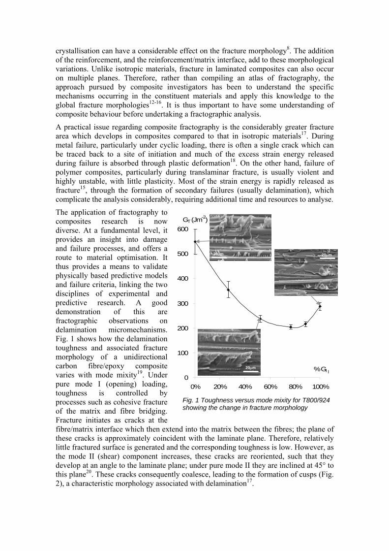
The application of fractography to composites research is now diverse. At a fundamental level, it provides an insight into damage and failure processes, and offers a route to material optimisation. It thus provides a means to validate physically based predictive models and failure criteria, linking the two disciplines of experimental and predictive research. A good demonstration of this are fractographic observations on delamination micromechanisms. Fig. 1 shows how the delamination toughness and associated fracture morphology of a unidirectional carbon fibre/epoxy composite varies with mode mixity19. Under pure mode I (opening) loading, toughness is controlled by processes such as cohesive fracture of the matrix and fibre bridging. Fracture initiates as cracks at the fibre/matrix interface which then extend into the matrix between the fibres; the plane of these cracks is approximately coincident with the laminate plane. Therefore, relatively little fractured surface is generated and the corresponding toughness is low. However, as the mode II (shear) component increases, these cracks are reoriented, such that they develop at an angle to the laminate plane; under pure mode II they are inclined at 45° to this plane20. These cracks consequently coalesce, leading to the formation of cusps (Fig. 2), a characteristic morphology associated with delamination17.
0
100
200
300
400
500
600
0% 20% 40% 60% 80% 100%
% GI
GT (Jm-2)
Fig. 1 Toughness versus mode mixity for T800/924 showing the change in fracture morphology
I 20µm
20µm 20µm
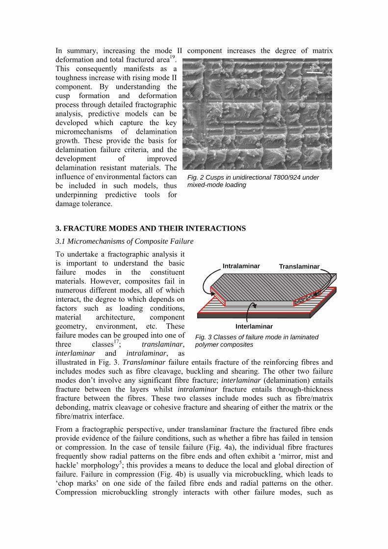
Fig. 3 Classes of failure mode in laminated polymer composites
Interlaminar
Translaminar
Intralaminar
In summary, increasing the mode II component increases the degree of matrix deformation and total fractured area19. This consequently manifests as a toughness increase with rising mode II component. By understanding the cusp formation and deformation process through detailed fractographic analysis, predictive models can be developed which capture the key micromechanisms of delamination growth. These provide the basis for delamination failure criteria, and the development of improved delamination resistant materials. The influence of environmental factors can be included in such models, thus underpinning predictive tools for damage tolerance.
3. FRACTURE MODES AND THEIR INTERACTIONS
3.1 Micromechanisms of Composite Failure
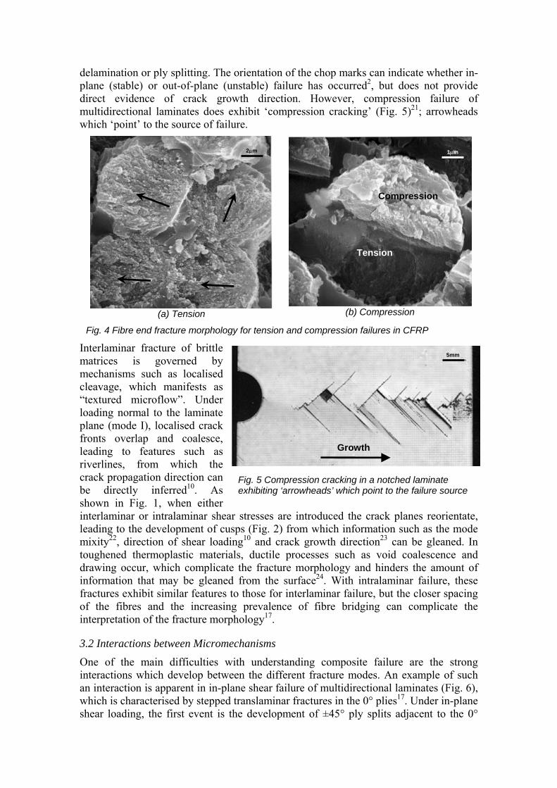
To undertake a fractographic analysis it is important to understand the basic failure modes in the constituent materials. However, composites fail in numerous different modes, all of which interact, the degree to which depends on factors such as loading conditions, material architecture, component geometry, environment, etc. These failure modes can be grouped into one of three classes17; translaminar, interlaminar and intralaminar, as illustrated in Fig. 3. Translaminar failure entails fracture of the reinforcing fibres and includes modes such as fibre cleavage, buckling and shearing. The other two failure modes don’t involve any significant fibre fracture; interlaminar (delamination) entails fracture between the layers whilst intralaminar fracture entails through-thickness fracture between the fibres. These two classes include modes such as fibre/matrix debonding, matrix cleavage or cohesive fracture and shearing of either the matrix or the fibre/matrix interface.
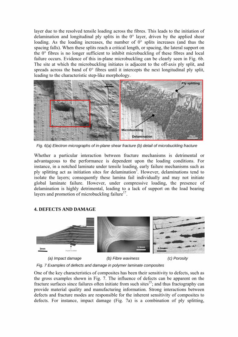
From a fractographic perspective, under translaminar fracture the fractured fibre ends provide evidence of the failure conditions, such as whether a fibre has failed in tension or compression. In the case of tensile failure (Fig. 4a), the individual fibre fractures frequently show radial patterns on the fibre ends and often exhibit a ‘mirror, mist and hackle’ morphology5; this provides a means to deduce the local and global direction of failure. Failure in compression (Fig. 4b) is usually via microbuckling, which leads to ‘chop marks’ on one side of the failed fibre ends and radial patterns on the other. Compression microbuckling strongly interacts with other failure modes, such as
Fig. 2 Cusps in unidirectional T800/924 under mixed-mode loading
20µm
delamination or ply splitting. The orientation of the chop marks can indicate whether in-plane (stable) or out-of-plane (unstable) failure has occurred2, but does not provide direct evidence of crack growth direction. However, compression failure of multidirectional laminates does exhibit ‘compression cracking’ (Fig. 5)21; arrowheads which ‘point’ to the source of failure.
(a) Tension
(b) Compression
Fig. 4 Fibre end fracture morphology for tension and compression failures in CFRP
Interlaminar fracture of brittle matrices is governed by mechanisms such as localised cleavage, which manifests as “textured microflow”. Under loading normal to the laminate plane (mode I), localised crack fronts overlap and coalesce, leading to features such as riverlines, from which the crack propagation direction can be directly inferred10. As shown in Fig. 1, when either interlaminar or intralaminar shear stresses are introduced the crack planes reorientate, leading to the development of cusps (Fig. 2) from which information such as the mode mixity22, direction of shear loading10 and crack growth direction23 can be gleaned. In toughened thermoplastic materials, ductile processes such as void coalescence and drawing occur, which complicate the fracture morphology and hinders the amount of information that may be gleaned from the surface24. With intralaminar failure, these fractures exhibit similar features to those for interlaminar failure, but the closer spacing of the fibres and the increasing prevalence of fibre bridging can complicate the interpretation of the fracture morphology17.
3.2 Interactions between Micromechanisms
One of the main difficulties with understanding composite failure are the strong interactions which develop between the different fracture modes. An example of such an interaction is apparent in in-plane shear failure of multidirectional laminates (Fig. 6), which is characterised by stepped translaminar fractures in the 0° plies17. Under in-plane shear loading, the first event is the development of ±45° ply splits adjacent to the 0°
Fig. 5 Compression cracking in a notched laminate exhibiting ‘arrowheads’ which point to the failure source
5mm
Growth
Tension
Compression
2µm 1µm
layer due to the resolved tensile loading across the fibres. This leads to the initiation of delamination and longitudinal ply splits in the 0° layer, driven by the applied shear loading. As the loading increases, the number of 0° splits increases (and thus the spacing falls). When these splits reach a critical length, or spacing, the lateral support on the 0° fibres is no longer sufficient to inhibit microbuckling of these fibres and local failure occurs. Evidence of this in-plane microbuckling can be clearly seen in Fig. 6b. The site at which the microbuckling initiates is adjacent to the off-axis ply split, and spreads across the band of 0° fibres until it intercepts the next longitudinal ply split, leading to the characteristic step-like morphology.
Whether a particular interaction between fracture mechanisms is detrimental or advantageous to the performance is dependent upon the loading conditions. For instance, in a notched laminate under tensile loading, early failure mechanisms such as ply splitting act as initiation sites for delamination3. However, delaminations tend to isolate the layers; consequently these lamina fail individually and may not initiate global laminate failure. However, under compressive loading, the presence of delamination is highly detrimental, leading to a lack of support on the load bearing layers and promotion of microbuckling failure17.
4. DEFECTS AND DAMAGE
(a) Impact damage (b) Fibre waviness (c) Porosity
Fig. 7 Examples of defects and damage in polymer laminate composites
One of the key characteristics of composites has been their sensitivity to defects, such as the gross examples shown in Fig. 7. The influence of defects can be apparent on the fracture surfaces since failures often initiate from such sites25; and thus fractography can provide material quality and manufacturing information. Strong interactions between defects and fracture modes are responsible for the inherent sensitivity of composites to defects. For instance, impact damage (Fig. 7a) is a combination of ply splitting,
Delamination
Microbuckling
Ply splitting
Fig. 6(a) Electron micrographs of in-plane shear fracture (b) detail of microbuckling fracture
60µm
20µm
3mm 0.2mm 1.5mm
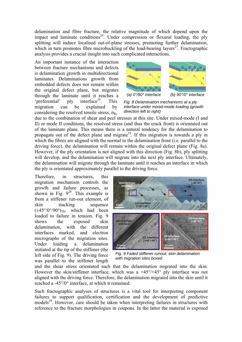
Fig. 8 Delamination mechanisms at a ply interface under mixed-mode loading (growth direction left to right)
delamination and fibre fracture, the relative magnitude of which depend upon the impact and laminate conditions26. Under compression or flexural loading, the ply splitting will induce localised out-of-plane stresses, promoting further delamination, which in turn promotes fibre microbuckling of the load-bearing layers27. Fractographic analysis provides a crucial insight into such complicated interactions.
An important instance of the interaction between fracture mechanisms and defects is delamination growth in multidirectional laminates. Delaminations growth from embedded defects does not remain within the original defect plane, but migrates through the laminate until it reaches a ‘preferential’ ply interface19. This migration can be explained by considering the resolved tensile stress, σR, due to the combination of shear and peel stresses at this site. Under mixed-mode (I and II) or mode II conditions, the resolved stress (and thus the crack front) is orientated out of the laminate plane. This means there is a natural tendency for the delamination to propagate out of the defect plane and migrate19. If this migration is towards a ply in which the fibres are aligned with the normal to the delamination front (i.e. parallel to the driving force), the delamination will remain within the original defect plane (Fig. 8a). However, if the ply orientation is not aligned with this direction (Fig. 8b), ply splitting will develop, and the delamination will migrate into the next ply interface. Ultimately, the delamination will migrate through the laminate until it reaches an interface in which the ply is orientated approximately parallel to the driving force.
Therefore, in structures, this migration mechanism controls the growth and failure processes, as shown in Fig. 928. This example is from a stiffener run-out element, of skin stacking sequence (±45°/0°/90°)3S, which had been loaded to failure in tension. Fig. 9 shows the exposed skin delamination, with the different interfaces marked, and electron micrographs of the migration sites. Under loading a delamination initiated at the tip of the stiffener (the left side of Fig. 9). The driving force was parallel to the stiffener length and the shear stress orientated such that the delamination migrated into the skin. However the skin/stiffener interface, which was a +45°/+45° ply interface was not aligned with the driving force. Therefore, the delamination migrated into the skin until it reached a -45°/0° interface, at which it remained.
Such fractographic analyses of structures is a vital tool for interpreting component failures to support qualification, certification and the development of predictive models29. However, care should be taken when interpreting failures in structures with reference to the fracture morphologies in coupons. In the latter the material is exposed
σ R
σR
ϕ
σ R ϕ
σ R
(a) 0°/90° interface (b) 90°/0° interface
Fig. 9 Failed stiffener runout; skin delamination with migration sites boxed
Skin/StringerInterface
1/2 Interface[+45°/-45°]
2/3 Interface[-45°/0°]
0°
-
Skin/StringerInterface
1/2 Interface[+45°/-45°]
1/2 Interface[+45°/-45°]
2/3 Interface[-45°/0°]
20mm
0.1mm 0.1mm
to uniform stress states, so the fracture morphology tends to be fairly uniform. However, in structures, particularly at features such as notches, tapers and corner radii, high stress gradients exist and therefore the fracture morphology can rapidly change. This can lead to difficulties in interpreting the failures. Finally, there can be considerable manufacturing variations between coupons and structures. In particular, defects such as fibre waviness (Fig. 7b) and porosity (Fig. 7c) are more prevalent in structures, and often act as initiation sites for failure.
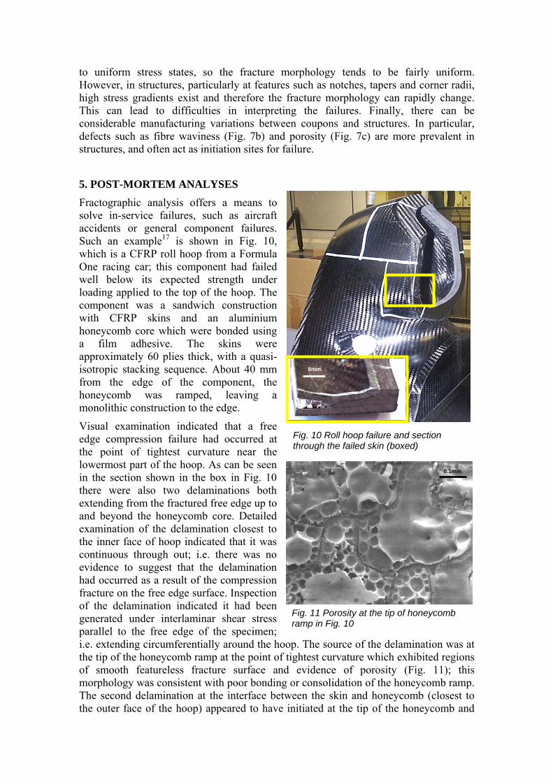
5. POST-MORTEM ANALYSES Fractographic analysis offers a means to solve in-service failures, such as aircraft accidents or general component failures. Such an example17 is shown in Fig. 10, which is a CFRP roll hoop from a Formula One racing car; this component had failed well below its expected strength under loading applied to the top of the hoop. The component was a sandwich construction with CFRP skins and an aluminium honeycomb core which were bonded using a film adhesive. The skins were approximately 60 plies thick, with a quasi-isotropic stacking sequence. About 40 mm from the edge of the component, the honeycomb was ramped, leaving a monolithic construction to the edge.
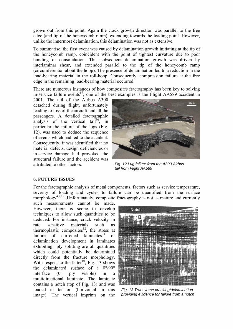
Visual examination indicated that a free edge compression failure had occurred at the point of tightest curvature near the lowermost part of the hoop. As can be seen in the section shown in the box in Fig. 10 there were also two delaminations both extending from the fractured free edge up to and beyond the honeycomb core. Detailed examination of the delamination closest to the inner face of hoop indicated that it was continuous through out; i.e. there was no evidence to suggest that the delamination had occurred as a result of the compression fracture on the free edge surface. Inspection of the delamination indicated it had been generated under interlaminar shear stress parallel to the free edge of the specimen; i.e. extending circumferentially around the hoop. The source of the delamination was at the tip of the honeycomb ramp at the point of tightest curvature which exhibited regions of smooth featureless fracture surface and evidence of porosity (Fig. 11); this morphology was consistent with poor bonding or consolidation of the honeycomb ramp. The second delamination at the interface between the skin and honeycomb (closest to the outer face of the hoop) appeared to have initiated at the tip of the honeycomb and
Fig. 10 Roll hoop failure and section through the failed skin (boxed)
8mm
Fig. 11 Porosity at the tip of honeycomb ramp in Fig. 10
0.1mm
grown out from this point. Again the crack growth direction was parallel to the free edge (and tip of the honeycomb ramp), extending towards the loading point. However, unlike the innermost delamination, this delamination was not as extensive.
To summarise, the first event was caused by delamination growth initiating at the tip of the honeycomb ramp, coincident with the point of tightest curvature due to poor bonding or consolidation. This subsequent delamination growth was driven by interlaminar shear, and extended parallel to the tip of the honeycomb ramp (circumferential about the hoop). The presence of delamination led to a reduction in the load-bearing material in the roll-hoop. Consequently, compression failure at the free edge in the remaining load-bearing material occurred.
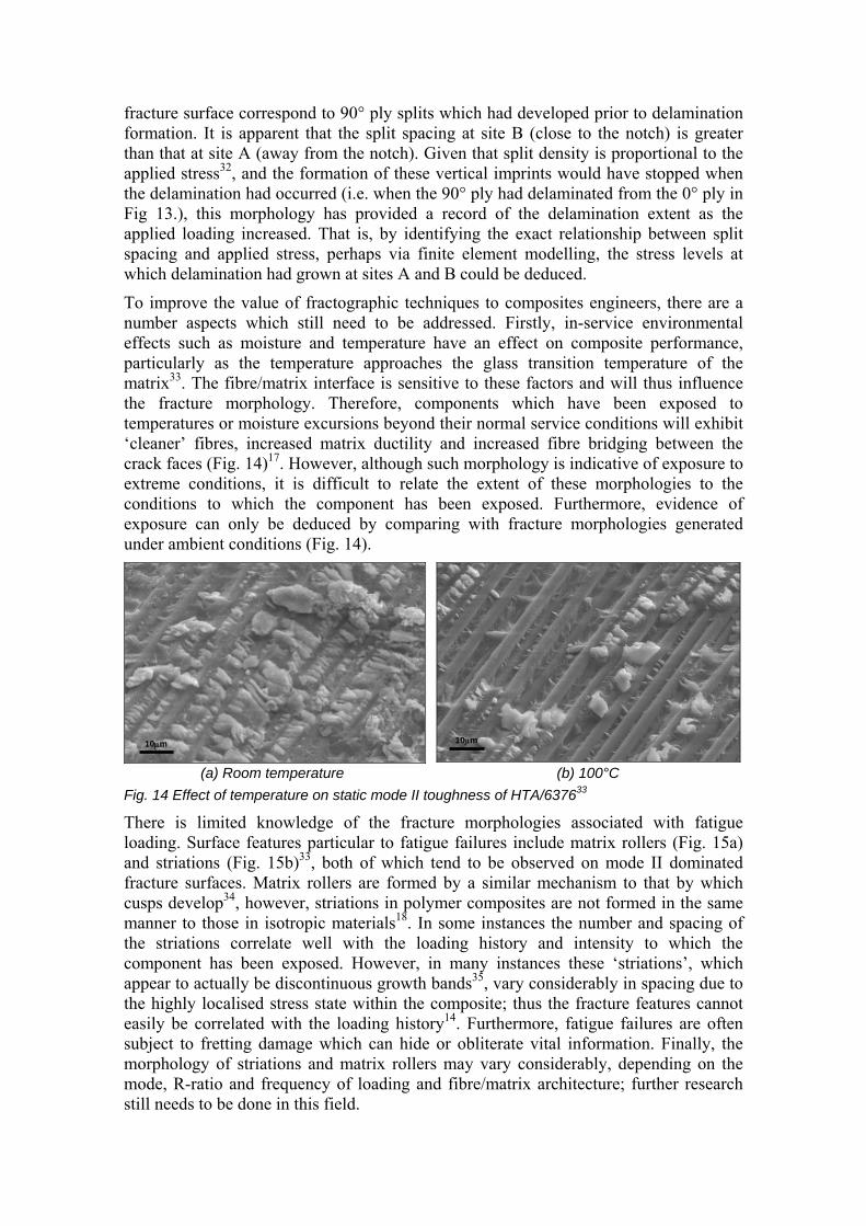
There are numerous instances of how composites fractography has been key to solving in-service failure events17; one of the best examples is the Flight AA589 accident in 2001. The tail of the Airbus A300 detached during flight, unfortunately leading to loss of the aircraft and all the passengers. A detailed fractographic analysis of the vertical tail30, in particular the failure of the lugs (Fig. 12), was used to deduce the sequence of events which had led to the accident. Consequently, it was identified that no material defects, design deficiencies or in-service damage had provoked the structural failure and the accident was attributed to other factors.
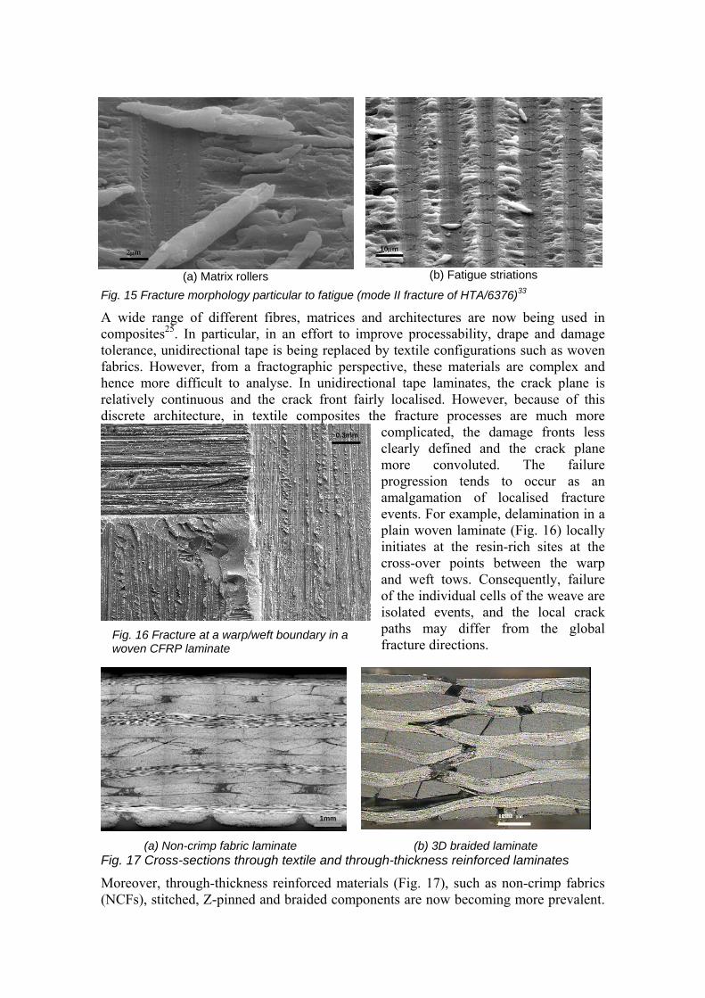
6. FUTURE ISSUES For the fractographic analysis of metal components, factors such as service temperature, severity of loading and cycles to failure can be quantified from the surface morphology4,7,18. Unfortunately, composite fractography is not as mature and currently such measurements cannot be made. However, there is scope to develop techniques to allow such quantities to be deduced. For instance, crack velocity in rate sensitive materials such as thermoplastic composites12, the stress at failure of corroded laminates31 or delamination development in laminates exhibiting ply splitting are all quantities which could potentially be determined directly from the fracture morphology. With respect to the latter10, Fig. 13 shows the delaminated surface of a 0°/90° interface (0° ply visible) in a multidirectional laminate. The laminate contains a notch (top of Fig. 13) and was loaded in tension (horizontal in this image). The vertical imprints on the
Fig. 12 Lug failure from the A300 Airbus tail from Flight AA589
10cm
Fig. 13 Transverse cracking/delamination providing evidence for failure from a notch
0°
90°
Notch
0.1mm
fracture surface correspond to 90° ply splits which had developed prior to delamination formation. It is apparent that the split spacing at site B (close to the notch) is greater than that at site A (away from the notch). Given that split density is proportional to the applied stress32, and the formation of these vertical imprints would have stopped when the delamination had occurred (i.e. when the 90° ply had delaminated from the 0° ply in Fig 13.), this morphology has provided a record of the delamination extent as the applied loading increased. That is, by identifying the exact relationship between split spacing and applied stress, perhaps via finite element modelling, the stress levels at which delamination had grown at sites A and B could be deduced.
To improve the value of fractographic techniques to composites engineers, there are a number aspects which still need to be addressed. Firstly, in-service environmental effects such as moisture and temperature have an effect on composite performance, particularly as the temperature approaches the glass transition temperature of the matrix33. The fibre/matrix interface is sensitive to these factors and will thus influence the fracture morphology. Therefore, components which have been exposed to temperatures or moisture excursions beyond their normal service conditions will exhibit ‘cleaner’ fibres, increased matrix ductility and increased fibre bridging between the crack faces (Fig. 14)17. However, although such morphology is indicative of exposure to extreme conditions, it is difficult to relate the extent of these morphologies to the conditions to which the component has been exposed. Furthermore, evidence of exposure can only be deduced by comparing with fracture morphologies generated under ambient conditions (Fig. 14).
(a) Room temperature (b) 100°C Fig. 14 Effect of temperature on static mode II toughness of HTA/637633
There is limited knowledge of the fracture morphologies associated with fatigue loading. Surface features particular to fatigue failures include matrix rollers (Fig. 15a) and striations (Fig. 15b)33, both of which tend to be observed on mode II dominated fracture surfaces. Matrix rollers are formed by a similar mechanism to that by which cusps develop34, however, striations in polymer composites are not formed in the same manner to those in isotropic materials18. In some instances the number and spacing of the striations correlate well with the loading history and intensity to which the component has been exposed. However, in many instances these ‘striations’, which appear to actually be discontinuous growth bands35, vary considerably in spacing due to the highly localised stress state within the composite; thus the fracture features cannot easily be correlated with the loading history14. Furthermore, fatigue failures are often subject to fretting damage which can hide or obliterate vital information. Finally, the morphology of striations and matrix rollers may vary considerably, depending on the mode, R-ratio and frequency of loading and fibre/matrix architecture; further research still needs to be done in this field.
10µm 10µm
(a) Matrix rollers
(b) Fatigue striations
Fig. 15 Fracture morphology particular to fatigue (mode II fracture of HTA/6376)33
A wide range of different fibres, matrices and architectures are now being used in composites25. In particular, in an effort to improve processability, drape and damage tolerance, unidirectional tape is being replaced by textile configurations such as woven fabrics. However, from a fractographic perspective, these materials are complex and hence more difficult to analyse. In unidirectional tape laminates, the crack plane is relatively continuous and the crack front fairly localised. However, because of this discrete architecture, in textile composites the fracture processes are much more
complicated, the damage fronts less clearly defined and the crack plane more convoluted. The failure progression tends to occur as an amalgamation of localised fracture events. For example, delamination in a plain woven laminate (Fig. 16) locally initiates at the resin-rich sites at the cross-over points between the warp and weft tows. Consequently, failure of the individual cells of the weave are isolated events, and the local crack paths may differ from the global fracture directions.
(a) Non-crimp fabric laminate (b) 3D braided laminate
Fig. 17 Cross-sections through textile and through-thickness reinforced laminates
Moreover, through-thickness reinforced materials (Fig. 17), such as non-crimp fabrics (NCFs), stitched, Z-pinned and braided components are now becoming more prevalent.
2µm 10µm
Fig. 16 Fracture at a warp/weft boundary in a woven CFRP laminate
0.3mm
1mm
Rather than two scales of microstructure (fibre and lamina), the through-thickness reinforcement leads to three scales; fibre, tow/bundle and lamina. This further complicates the fracture morphology and encourages interaction between the different fracture mechanisms such as delamination, splitting and fibre fracture. Furthermore, the through-thickness reinforcement introduces crimp into the fibre tows, which promotes mechanisms such as localised delamination and fibre microbuckling. Finally, in these materials the through-thickness reinforcement does not appear to fracture cleanly, and consequently the fracture planes are not well defined. Thus from a practical perspective, it becomes very difficult to separate and expose the fracture surfaces for inspection without damaging them. As the use of these materials increases, further fractographic studies to understand the complex interaction between different fracture mechanisms will be needed.
7. CONCLUDING REMARKS Three parameters; stiffness, strength and toughness, principally define the mechanical performance of a material. A knowledge of the influencing of factors such as environment, processing, loading and initial damage state on these parameters is important to ensure efficient and safe design. The current understanding and predictive capabilities associated with polymer composite engineering design is well advanced, and considerable progress has been made in the development of characterisation methods and predictive tools. However, these need to keep pace with the rapid advancement of composite materials, such as new processing routes, architectures, constituent types, and applications and drivers for design. Of the three material parameters, toughness is the least well characterised. This is principally attributed to the diverse range of fracture modes in composites, and the interactions which can develop between them. Fractographic analysis, the examination of fracture surfaces to deduce information, is key to understanding and modelling toughness since it provides an insight into the physical processes by which composites are damaged and fail.
This paper has described the current status of fractographic analysis of composites, and shown that the techniques are well developed, allowing the interpretation of most failures that occur in composite structures. The fracture morphologies associated with translaminar classes of failure, such as tension, compression, flexure and in-plane shear, and those associated with matrix dominated classes such interlaminar and intralaminar failure, including matrix and fibre/matrix interfacial cleavage and shear, are well characterised. The influence of environment, loading, processing and damage on these fracture modes are also reasonably well defined. The interactions between these failure modes are well understood, so these fracture modes can be sequenced, allowing the failure progression in structures and components to be deduced.
However, there is still scope to bring composites fractography to a level of maturity akin to that of isotropic materials. In particular, further research needs to be done to relate fracture morphologies to semi-qualitative parameters relating to the loading history and conditions at failure. Furthermore, the influence of factors such as environment (moisture and temperature) and cyclic loading still need to be addressed in some newer materials. As composite architectures move towards increased use of through-thickness reinforced materials, fractographic techniques need to be developed by which such materials can be analysed. Newer thermoplastic materials, which are strain rate sensitive and have morphologies that are dependent on crystallinity, will also require further study. However, composites fractography is proving to be powerful and
reliable tool for the composite engineer, and is a vital technique for the overall development of composite structures.
8. REFERENCES 1. Hinton, M. J., Soden, P. & Kaddour, A. Failure Criteria in Fibre-Reinforced-
Polymer Composites. Elsevier, (2004). 2. Soutis, C. & Curtis, P. T. A method for predicting the fracture toughness of CFRP
laminates failing by fibre microbuckling. Composites Part A: Applied Science and Manufacturing 31, 733-740 (2000).
3. Wisnom, M. R., Khan, B. & Hallett, S. R. Size effects in unnotched tensile strength of unidirectional and quasi-isotropic carbon/epoxy laminates. Composite Structures 84, 21-28 (2008).
4. Lynch, S. P. & Moutsos, S. A brief history of fractography. Journal of Failure Analysis and Prevention 6, 54-69 (2006).
5. Hull, D. Fractography : observing, measuring, and interpreting fracture surface topography. Cambridge University Press (1999).
6. Thomas, A. L. & Pollard, D. D. The geometry of echelon fractures in rock - implications from laboratory and numerical experiments. Journal of Structural Geology 15, 323-334 (1993).
7. Parrington, R. J. Fractography of metals and plastics. Journal of Failure Analysis and Prevention 2, 16-19 (2002).
8. Roulin-Moloney, A. C. Fractography and Failure Mechanisms of Polymers and Composites. Elsevier (1989).
9. Morris, G. E. Determining Fracture Directions And Fracture Origins On Failed Graphite/Epoxy Surfaces. Damage in Composite Materials, (ASTM STP 775), 274-297 (1979).
10. Purslow, D. Some fundamental aspects of composites fractography. Composites 12, 241-247 (1981).
11. McCoy, R. A. SEM fractography and failure analysis of nonmetallic materials. Journal of Failure Analysis and Prevention 4, 58-64 (2007).
12. Baas, S. J. W. GARTEUR AG14: Fractography of Composites. GARTEUR TP No 083. (1994).
13. Hiley, M. GARTEUR AG20 Fractographic Aspects of Fatigue Failure in Composite Materials. DERA/MSS/MSMA2/TR000168 / GARTEUR Final Report TP112. (2001).
14. Hiley, M. GARTEUR AG27 Fractographic Aspects of Fatigue Failure in Complex Laminates and Structures. GARTEUR Final Report TP-151 (2007).
15. Friedrich, K. Application of Fracture Mechanics to Composite Materials. Friedrich, K. (ed.), pp. 425-486 (Elsevier) (1987).
16. Franz, H. E. Microfractography of fibre reinforced composite materials. Praktische Metallographie 28, 404-419 (1991).
17. Greenhalgh, E. S. Failure analysis and fractography of polymer composites. Woodhead Publishing, Cambridge (2008).
18. ASM International ASM Handbook - Volume 12 Fractography. (2002). 19. Greenhalgh, E. S. Characterisation of Mixed-Mode Delamination Growth in
Carbon-Fibre Composites. Imperial College PhD Thesis (1998). 20. Fleck, N. A. Brittle fracture due to an array of microcracks. Proceedings of the
Royal Society of London, Series A (Mathematical and Physical Sciences) 432, 55-76 (1991).
21. Greenhalgh, E. S. & Cox, P. C. A method to determine propagation direction of compressive fracture in carbon-fibre composites. Composite Structures 21, 1-7 (1992).
22. Greenhalgh, E. S. & Matthews, F. L. Characterisation of mixed-mode fracture in unidirectional laminates. Proceedings of 7th European Conference on Composite Materials, 14-16 May, London, UK, Woodhead Publishing. vol.1, 135-140 (1996).
23. Singh, S. & Greenhalgh, E. Micromechanisms of interlaminar fracture in carbon fibre reinforced plastics at multidirectional ply interfaces under static and cyclic loading. Plastics, Rubber and Composites Processing and Applications 27, 220-226 (1998).
24. Purslow, D. Matrix fractography of fibre-reinforced thermoplastics. II. Shear failures. Composites 19, 115-126 (1988).
25. Astrom, B. T. Manufacturing of Polymer Composites. Chapman & Hall, (1997). 26. Davies, G. A. O. & Olsson, R. Impact in aerospace composite structures. The
Aeronautical Journal 108, 541-563 (2004). 27. Greenhalgh, E. S. & Hiley, M. The assessment of novel materials and processes
for the impact tolerant design of stiffened composite aerospace structures. Composites Part A: Applied Science and Manufacturing 34, 151-161 (2003).
28. Greenhalgh, E. S. & Huertas Garcia, M. Fracture mechanisms and failure processes at stiffener run-outs in polymer matrix composite stiffened elements. Composites Part A: Applied Science and Manufacturing 35, 1447-1458 (2004).
29. Ireman, T. et al. Damage propagation in composite structural elements - coupon experiments and analyses. Composite Structures 36, 209-220 (1996).
30. Fox, M. R., Schultheisz, C. R. & Reeder, J. R. Fractographic examination of the vertical stabilizer and rudder from American Airlines Flight 587. 46th AIAA/ASME/ASCE/AHS/ASC Structures, Structural Dynamics and Materials, Austin, TX, United States (2005).
31. Sapalidis, S., Hogg, P. & Youd, S. High temperature acidic stress corrosion of glass fibre composites Part I Effect of fibre type. Journal of Materials Science 32, 309-316 (1997).
32. Friedrich, K. Application of Fracture Mechanics to Composite Materials. Elsevier (1987).
33. Greenhalgh, E. S. & Singh, S. The effect of moisture, matrix and ply orientation on delamination resistance, failure criteria and fracture morphology in CFRP. Composite Materials: Testing, Design, and Acceptance Criteria, Mar 26-27, Phoenix, AZ, United States, (ASTM STP 1416), 221-234 (2002).
34. Sjogren, A., Asp, L. E., Greenhalgh, E. S. & Hiley, M. J. Interlaminar crack propagation in CFRP: Effects of temperature and loading conditions on fracture morphology and toughness. Composite Materials: Testing, Design, and Acceptance Criteria, Mar 26-27, Phoenix, AZ, United States, (ASTM STP 1416), 2351-252 (2002).
35. Hertzberg, R. & Manson, J. Fatigue of Engineering Plastics. Academic Press, New York (1980).