Fractography of a neck failure in a double-modular hip implant
6
Case study Fractography of a neck failure in a double-modular hip implant Jason J. Williams, Nikhilesh Chawla * Materials Science and Engineering, Arizona State University, Tempe, AZ 85287-6106, USA 1. Introduction Double-modular hip implants consist of a neck that is separate from both the stem and the head – the three parts fit together via tapered joints. Several necks and heads of different geometries are available, allowing the surgeon to optimize the hip angle, hip offset and leg length during surgery. However, concerns exist about the stability of the tapered joints used to connect the neck to the head and stem [1,2]. Specifically, tapered joints are susceptible to fretting and crevice-corrosion, which may lead to loosening, release of toxic metal ions and mechanical failure. A study that followed 5000 double-modular hip implants (Metha Short Hip Stem Prosthesis) between 2004 and 2008 found that 1.4% of the titanium necks failed after approximately two years [3]. Most of the failures were attributed to the formation of microcracks on the anterolateral surface (i.e., toward the front and outside of the body) of the neck due to fretting and corrosion inside the tapered joint between the neck and stem. This damage led to the formation of a fatigue crack, and ultimately, complete fracture of the neck. According to Ref. [3], risk factors for neck failure included being male, heavier, more active, and having a sharper hip angle. Three additional case reports of neck failures have been published on the same model of hip implant as this study’s (Wright Medical Technology’s Profemur 1 Z) [4–6]. All three reports found neck fracture to be caused by a fatigue crack which originated inside the tapered joint on the anterolateral surface of the neck, identical to those of Ref. [3]. All three reports also suggest fretting and/or corrosion played a role in the neck failures. However, no clear fatigue crack nucleation site was shown, possibly because of damage incurred after neck failure. This study does show a clear nucleation site, and comes to similar conclusions for failure as these aforementioned studies. Case Studies in Engineering Failure Analysis 2 (2014) 45–50 A R T I C L E I N F O Article history: Received 7 October 2013 Received in revised form 20 December 2013 Accepted 26 March 2014 Available online 8 April 2014 Keywords: Profemur Hip Fretting Corrosion Fatigue Fractography A B S T R A C T The tapered joints of modular hip implants are prone to fretting and crevice-corrosion. This can lead to total failure in under a year, especially for heavier, more active implant recipients. In this study, fractography of a failed Profemur Z implant showed that a life limiting fatigue crack was nucleated on the anterolateral surface of the implant’s neck. The fatigue crack nucleation area appeared to have both more fretting damage and a higher corrosion rate than on other surfaces of the neck. ß 2014 The Authors. Published by Elsevier Ltd. This is an open access article under the CC BY-NC-ND license (http://creativecommons.org/licenses/by-nc-nd/3.0/). * Corresponding author. Tel.: +1 011 4809652402. E-mail address: [email protected] (N. Chawla). Contents lists available at ScienceDirect Case Studies in Engineering Failure Analysis jo ur n al ho m ep ag e: ww w.els evier .c om /lo cat e/c s efa http://dx.doi.org/10.1016/j.csefa.2014.03.001 2213-2902/ß 2014 The Authors. Published by Elsevier Ltd. This is an open access article under the CC BY-NC-ND license (http://creativecommons.org/ licenses/by-nc-nd/3.0/).
Transcript of Fractography of a neck failure in a double-modular hip implant

Case Studies in Engineering Failure Analysis 2 (2014) 45–50
Contents lists available at ScienceDirect
Case Studies in Engineering Failure Analysis
jo ur n al ho m ep ag e: ww w.els evier . c om / lo cat e/c s efa
Case study
Fractography of a neck failure in a double-modular hip
implantJason J. Williams, Nikhilesh Chawla *
Materials Science and Engineering, Arizona State University, Tempe, AZ 85287-6106, USA
A R T I C L E I N F O
Article history:
Received 7 October 2013
Received in revised form 20 December 2013
Accepted 26 March 2014
Available online 8 April 2014
Keywords:
Profemur
Hip
Fretting
Corrosion
Fatigue
Fractography
A B S T R A C T
The tapered joints of modular hip implants are prone to fretting and crevice-corrosion.
This can lead to total failure in under a year, especially for heavier, more active implant
recipients. In this study, fractography of a failed Profemur Z implant showed that a life
limiting fatigue crack was nucleated on the anterolateral surface of the implant’s neck. The
fatigue crack nucleation area appeared to have both more fretting damage and a higher
corrosion rate than on other surfaces of the neck.
� 2014 The Authors. Published by Elsevier Ltd. This is an open access article under the CC
BY-NC-ND license (http://creativecommons.org/licenses/by-nc-nd/3.0/).
1. Introduction
Double-modular hip implants consist of a neck that is separate from both the stem and the head – the three parts fittogether via tapered joints. Several necks and heads of different geometries are available, allowing the surgeon to optimizethe hip angle, hip offset and leg length during surgery. However, concerns exist about the stability of the tapered joints usedto connect the neck to the head and stem [1,2]. Specifically, tapered joints are susceptible to fretting and crevice-corrosion,which may lead to loosening, release of toxic metal ions and mechanical failure.
A study that followed 5000 double-modular hip implants (Metha Short Hip Stem Prosthesis) between 2004 and 2008found that 1.4% of the titanium necks failed after approximately two years [3]. Most of the failures were attributed to theformation of microcracks on the anterolateral surface (i.e., toward the front and outside of the body) of the neck due tofretting and corrosion inside the tapered joint between the neck and stem. This damage led to the formation of a fatiguecrack, and ultimately, complete fracture of the neck. According to Ref. [3], risk factors for neck failure included being male,heavier, more active, and having a sharper hip angle.
Three additional case reports of neck failures have been published on the same model of hip implant as this study’s(Wright Medical Technology’s Profemur1 Z) [4–6]. All three reports found neck fracture to be caused by a fatigue crack whichoriginated inside the tapered joint on the anterolateral surface of the neck, identical to those of Ref. [3]. All three reports alsosuggest fretting and/or corrosion played a role in the neck failures. However, no clear fatigue crack nucleation site wasshown, possibly because of damage incurred after neck failure. This study does show a clear nucleation site, and comes tosimilar conclusions for failure as these aforementioned studies.
* Corresponding author. Tel.: +1 011 4809652402.
E-mail address: [email protected] (N. Chawla).
http://dx.doi.org/10.1016/j.csefa.2014.03.001
2213-2902/� 2014 The Authors. Published by Elsevier Ltd. This is an open access article under the CC BY-NC-ND license (http://creativecommons.org/
licenses/by-nc-nd/3.0/).

J.J. Williams, N. Chawla / Case Studies in Engineering Failure Analysis 2 (2014) 45–5046
2. Experimental
The implant recipient was described as an active 47-year-old male, weighing 84 kg. The implant consisted of a size 3Profemur1 Z stem, 8 degree varus neck, and a �3.5 mm � 50 mm Conserve1 Total Class-A head. Both the neck and stem weremade of Ti–6Al–4V, and the head was made of a cobalt-chrome alloy. The neck of this implant failed after three years(implanted in 2006, failed and removed in 2009). Due to legal reasons, the parts were examined in the as-received condition(no cleaning, cutting, etc.) using a scanning electron microscope (JEOL 6100) in 2011.
3. Results
Fig. 1 shows optical photographs of both fracture surfaces, as well as a model of where fracture occurred in relation to themodular hip implant. After fracture, one piece of the neck remained inside the stem’s female taper; the other piece remained
Fig. 1. (a) Optical photograph of the fracture surface of the neck that remained in the stem. The surgical damage was created by a tool used to remove the
implant from the body. (b) Optical photograph of the fracture surface of the neck that remained attached to the head. Post-fracture damage occurred when
the fractured neck slid across the inside of the stem’s taper surface. (c) Exploded model of the modular hip implant, showing where neck fracture occurred.
Both the neck and stem were made of Ti–6Al–4V.

J.J. Williams, N. Chawla / Case Studies in Engineering Failure Analysis 2 (2014) 45–50 47
attached to the head. The piece of the neck that remained in the stem was damaged by the surgeon during removal of theimplant from the body. This surgical damage occurred near the overloaded portion of the fracture surface – the fatigue cracknucleation site remained pristine. In contrast, the piece of the neck that remained connected to the head was not damagedduring surgery, but it was damaged when the fractured neck slid out of the stem’s female taper after overload. Unfortunately,this post-fracture damaged ruined the areas of the taper surface and fracture surface that coincided with fatigue cracknucleation. Thus, only the stem-side neck was examined further for crack nucleation causes. The head-side neck was used toassess the extent of fretting and corrosion between the surfaces of the Morse taper joint.
Visually, the neck surfaces that remained outside of the tapered joint were shiny, with no obvious signs of corrosion. Theneck surfaces inside the Morse taper, however, were darkened and appeared corroded. SEM images of these surfaces areshown in Fig. 2 and confirmed the visual inspection. Outside the tapered joint, the surfaces were uniform with original
Fig. 2. (a) Secondary electron image of the surface of the neck’s Morse taper located outside the joint’s contact area. This surface was uniform and showed
original machining marks, which run perpendicular to the long axis of the neck (the long axis of neck runs from top to bottom in this image, with the head
side at top). (b) Secondary electron image of the surface of the neck’s Morse taper located inside the joint’s contact area. Most of the surface was corroded
and fretted. (Orientation is same as in (a).)

J.J. Williams, N. Chawla / Case Studies in Engineering Failure Analysis 2 (2014) 45–5048
machine marks evident. Inside the joint, the surfaces were extremely non-uniform and roughened, indicative of crevice-corrosion. Areas of fretting were also observed, somewhat less frequently than corroded areas. As mentioned earlier,however, the anterolateral portion of the taper surface that was expected to contain the highest degree of fretting wasdamaged after fracture as the neck slid out of the stem. Only a very small fraction of the tapered surface that was inside thejoint was free of fretting or corrosion.
Signs of corrosion were also observed while imaging the fracture surface. Fig. 3 shows secondary and backscatteredelectron images of the fracture surface, taken at the interface between the neck and the stem. The brightest phase in thebackscattered image is the titanium alloy. It is unclear whether the darker phase at the joint interface is a solid corrosionproduct or residue left after desiccation of body fluids. No EDS was performed because the fracture surface of the neck wasrecessed too far into the stem to yield quality X-ray spectra at this joint interface. Regardless, the jagged edge of the titaniumneck and the gap between the neck and stem is indicative of corrosion. The entire circumference of the fracture surface wasseparated from the stem by 10–80 mm, giving an average corrosion rate of about 15 mm/yr.
Fig. 3. (a) Secondary electron image of the stem–neck joint interface at the fatigue-fracture plane. (b) Backscattered electron image of the same area. The
entire circumference of the neck along the fatigue-fracture plane was corroded.
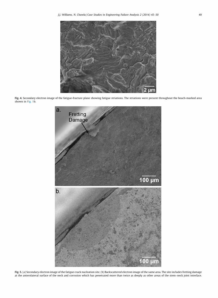
Fig. 4. Secondary electron image of the fatigue-fracture plane showing fatigue striations. The striations were present throughout the beach-marked area
shown in Fig. 1b.
Fig. 5. (a) Secondary electron image of the fatigue crack nucleation site. (b) Backscattered electron image of the same area. The site includes fretting damage
at the anterolateral surface of the neck and corrosion which has penetrated more than twice as deeply as other areas of the stem–neck joint interface.
J.J. Williams, N. Chawla / Case Studies in Engineering Failure Analysis 2 (2014) 45–50 49

J.J. Williams, N. Chawla / Case Studies in Engineering Failure Analysis 2 (2014) 45–5050
Based on the optical photographs (Fig. 1), approximately 94% of the fracture surface area consisted of beach marksindicative of fatigue crack growth. Only 6% of the area was from the final overloaded fracture. SEM images confirmed thepresence of a fatigue crack. In secondary electron images (Fig. 4), fatigue striations were clearly seen throughout the beach-marked area of Fig. 1b. Also, a distinct crack nucleation site was found (Fig. 5). The site appears to be a crack orientedperpendicularly to the fatigue crack and surrounded by a region different in chemical composition to that of the base alloy.Although it may have been a pre-existing flaw, the crack was likely created by fretting; and the zone surrounding it appearsto be the result of corrosion that was enhanced by the presence of this crack. If it were a preexisting flaw, one would expect tofind similar flaws on the surface of the taper outside the joint or on central areas of the fracture surface – neither wasobserved during this study. The penetration depth of corrosion at this nucleation site is more than twice that of all otherareas along the circumference of the fracture surface. Tapered joints in a variety of common engineering applications arenever considered leak tight without the use of an additional sealing mechanism (o-ring, grease, etc.). Given that no sealant isused in hip implants, some degree of fluid penetration into the joint is inevitable.
4. Conclusions
Based on the findings of this study and others, Ti–6Al–4V implants are susceptible to crevice-corrosion because of fluidpenetration. Furthermore, the load used during surgery to press-fit the tapered joint together appears to be inadequate, sincefretting damage has also been commonly observed. The combination of fretting and crevice-corrosion significantly reducesthe fatigue strength of the Ti–6Al–4V neck in double-modular hip implants.
References
[1] Bobyn JD, Tanzer M, Krygier JJ, Dujovne AR, Brooks CE. Concerns with modularity in total hip arthroplasty. Clin Orthop Relat Res 1994;298:27–36.[2] Kop AM, Swarts E. Corrosion of a hip stem with a modular neck taper junction: a retrieval study of 16 cases. J Arthroplasty 2009;24(7):1019–23.[3] Grupp TM, Weik T, Bloemer W, Knaebel H. Modular titanium alloy neck adapter failures in hip replacement – failure mode analysis and influence of
implant material. BMC Musculoskelet Disord 2010;11:3.[4] Wilson DAJ, Dunbar MJ, Amirault JD, Farhat Z. Early failure of a modular femoral neck total hip arthroplasty component. J Bone Joint Surg
2010;92(6):1514–7.[5] Dangles CJ, Altstetter CJ. Failure of the modular neck in a total hip arthroplasty. J Arthroplasty 2010;25(7):1169e5–9e7.[6] Wright G, Sporer S, Urban R, Jacobs J. Fracture of a modular femoral neck after total hip arthroplasty. J Bone Joint Surg 2010;92(6):1518–21.