
FR-E520-0.1KND to 7 - Mitsubishi Electric · 2007-11-29 · transistorized inverter fr-e500...
207
TRANSISTORIZED INVERTER FR-E500 FR-E520-0.1KND to 7.5KND INSTRUCTION MANUAL OUTLINE OPERATION/ CONTROL PARAMETERS SPECIFICATIONS INSTALLATION AND WIRING PROTECTIVE FUNCTIONS Chapter 6 Chapter 5 Chapter 4 Chapter 3 Chapter 2 Chapter 1
Transcript of FR-E520-0.1KND to 7 - Mitsubishi Electric · 2007-11-29 · transistorized inverter fr-e500...

TRANSISTORIZED INVERTERFR-E500
FR-E520-0.1KND to 7.5KND
INSTRUCTION MANUAL
OUTLINE
OPERATION/CONTROL
PARAMETERS
SPECIFICATIONS
INSTALLATIONAND WIRING
PROTECTIVEFUNCTIONS
Chapter 6
Chapter 5
Chapter 4
Chapter 3
Chapter 2
Chapter 1

A - 1
Thank you for choosing the Mitsubishi Transistorized inverter.
This instruction manual gives handling information and precautions for use of this
equipment.
Incorrect handling might cause an unexpected fault. Before using the inverter,
please read this manual carefully to use the equipment to its optimum.
Please forward this manual to the end user.
This section is specifically about safety mattersDo not attempt to install, operate, maintain or inspect the inverter until you have readthrough this instruction manual and appended documents carefully and can use theequipment correctly.
Do not use the inverter until you have a full knowledge of the equipment, safetyinformation and instructions.
In this manual, the safety instruction levels are classified into "WARNING" and"CAUTION".
Assumes that incorrect handling may cause hazardousconditions, resulting in death or severe injury.
Assumes that incorrect handling may cause hazardousconditions, resulting in medium or slight injury, or maycause physical damage only.
Note that even the CAUTION level may lead to a serious consequence according toconditions. Please follow the instructions of both levels because they are importantto personnel safety.
WARNING
CAUTION

A - 2
SAFETY INSTRUCTIONS
1. Electric Shock Prevention
WARNING! While power is on or when the inverter is running, do not open the front cover.
You may get an electric shock.! Do not run the inverter with the front cover removed. Otherwise, you may access
the exposed high-voltage terminals or the charging part of the circuitry and getan electric shock.
! If power is off, do not remove the front cover except for wiring or periodicinspection. You may access the charged inverter circuits and get an electricshock.
! Before starting wiring or inspection, switch power off, wait for more than 10minutes, and check for residual voltage with a meter (refer to chapter 2 forfurther details) etc.
! Earth the inverter.! Any person who is involved in the wiring or inspection of this equipment should
be fully competent to do the work.! Always install the inverter before wiring. Otherwise, you may get an electric
shock or be injured.! Operate the switches and potentiometers with dry hands to prevent an electric
shock.! Do not subject the cables to scratches, excessive stress, heavy loads or
pinching. Otherwise, you may get an electric shock.! Do not change the cooling fan while power is on.
It is dangerous to change the cooling fan while power is on.! While power is on, do not move the node address setting switches. Doing so
can cause an electric shock.
2. Fire Prevention
CAUTION! Mount the inverter and brake resistor on an incombustible surface. Installing the
inverter directly on or near a combustible surface could lead to a fire.! If the inverter has become faulty, switch off the inverter power. A continuous flow
of large current could cause a fire.! When a brake resistor is used, use an alarm signal to switch power off.
Otherwise, the brake resistor will overheat abnormally due a brake transistor orother fault, resulting in a fire.
! Do not connect a resistor directly to the DC terminals P (+), N (−). This couldcause a fire.

A - 3
3. Injury Prevention
CAUTION! Apply only the voltage specified in the instruction manual to each terminal to
prevent damage etc.! Ensure that the cables are connected to the correct terminals. Otherwise,
damage etc. may occur.! Always make sure that polarity is correct to prevent damage etc.! While power is on and for some time after power-off, do not touch the inverter or
brake resistor as they are hot and you may get burnt.
4. Additional instructions
Also note the following points to prevent an accidental failure, injury, electric shock, etc.
(1) Transportation and installation
CAUTION! When carrying products, use correct lifting gear to prevent injury.! Do not stack the inverter boxes higher than the number recommended.! Ensure that installation position and material can withstand the weight of the
inverter. Install according to the information in the Instruction Manual.! Do not operate if the inverter is damaged or has parts missing.! When carrying the inverter, do not hold the front cover or accessory cover.! Do not stand or rest heavy objects on the inverter.! Check the inverter mounting orientation is correct.! Prevent screws, wire fragments or other conductive bodies or oil or other
flammable substance from entering the inverter.! Do not drop the inverter, or subject it to impact.! Use the inverter under the following environmental conditions:
Ambienttemperature
Constant torque : -10°C to +50°C (non-freezing)
Ambient humidity 90%RH or less (non-condensing)Storagetemperature
-20°C to +65°C *
AmbienceIndoors (free from corrosive gas, flammable gas, oil mist, dustand dirt)E
nviro
nmen
t
Altitude, vibrationMaximum 1000m above sea level for standard operation. Afterthat derate by 3% for every extra 500m up to 2500m (91%).5.9m/s2 or less (conforming to JIS C 0040)
* Temperatures applicable for a short time, e.g. in transit.

A - 4
(2) Wiring
CAUTION! Do not fit capacitive equipment such as a power factor correction capacitor,
noise filter or surge suppressor to the output of the inverter.
! The connection orientation of the output cables U, V, W to the motor will affectthe direction of rotation of the motor.
(3) Trial run
CAUTION! Check all parameters, and ensure that the machine will not be damaged by a
sudden start-up.
(4) Operation
WARNING! When you have chosen the retry function, stay away from the equipment as it
will restart suddenly after an alarm stop.
! The load used should be a three-phase induction motor only. Connection of anyother electrical equipment to the inverter output may damage the equipment.
! Do not modify the equipment.
CAUTION! The electronic overcurrent protection does not guarantee protection of the motor
from overheating.! Do not use a magnetic contactor on the inverter input for frequent
starting/stopping of the inverter.! Use a noise filter to reduce the effect of electromagnetic interference. Otherwise
nearby electronic equipment may be affected.! Take measures to suppress harmonics. Otherwise power harmonics from the
inverter may heat/damage the power capacitor and generator.! When parameter clear or all clear is performed, each parameter returns to the
factory setting. Re-set the required parameters before starting operation.! The inverter can be easily set for high-speed operation. Before changing its
setting, fully examine the performances of the motor and machine.! In addition to the inverter's holding function, install a holding device to ensure
safety.! Before running an inverter which had been stored for a long period, always
perform inspection and test operation.

A - 5
(5) Emergency stop
CAUTION! Provide a safety backup such as an emergency brake which will prevent the
machine and equipment from hazardous conditions if the inverter fails.
(6) Maintenance, inspection and parts replacement
CAUTION! Do not carry out a megger (insulation resistance) test on the control circuit of the
inverter.
(7) Disposing of the inverter
CAUTION! Treat as industrial waste.
(8) General instructionsMany of the diagrams and drawings in this instruction manual show the inverterwithout a cover, or partially open. Never operate the inverter like this. Alwaysreplace the cover and follow this instruction manual when operating the inverter.

CONTENTS
I
1 OUTLINE 1
1.1 Pre-Operation Information ..........................................................................................1
1.1.1 Precautions for operation .....................................................................................1
1.2 Basic Configuration.....................................................................................................3
1.2.1 Basic configuration ...............................................................................................3
1.3 Structure .....................................................................................................................4
1.3.1 Appearance and structure ....................................................................................4
1.3.2 Functions..............................................................................................................4
1.3.3 Removal and reinstallation of the front cover .......................................................5
1.3.4 Removal and reinstallation of the wiring cover .....................................................6
1.3.5 Removal and reinstallation of the accessory cover ..............................................7
1.3.6 Exploded view ......................................................................................................8
2 INSTALLATION AND WIRING 9
2.1 Installation...................................................................................................................9
2.1.1 Instructions for installation....................................................................................9
2.2 Wiring........................................................................................................................11
2.2.1 Terminal connection diagram .............................................................................11
2.2.2 Wiring of the main circuit ....................................................................................14
2.2.3 Wiring of the control circuit .................................................................................18
2.2.4 DeviceNet communication signal wiring .............................................................21
2.2.5 Connection to the PU connector ........................................................................26
2.2.6 Connection of stand-alone option units ..............................................................29
2.2.7 Design information .............................................................................................32
2.3 Other Wiring..............................................................................................................33
2.3.1 Power supply harmonics ....................................................................................33
2.3.2 Japanese harmonic suppression guideline ........................................................34
2.3.3 Inverter-generated noise and reduction techniques ...........................................37
2.3.4 Leakage currents and countermeasures............................................................41
2.3.5 Peripheral devices..............................................................................................42
2.3.6 Instructions for compliance with U.S. and Canadian Electrical Codes ...............46
Co
nte
nts

II
3 OPERATION/CONTROL 47
3.1 Inverter Settings........................................................................................................47
3.1.1 Node address of the inverter ..............................................................................47
3.2 Configuration.............................................................................................................49
3.2.1 General description ............................................................................................49
3.2.2 Set baud rate:.....................................................................................................50
3.2.3 Set node address: ..............................................................................................50
3.2.4 DeviceNet I/O assembly: ....................................................................................50
3.3 Operation ..................................................................................................................52
3.3.1 Operation modes................................................................................................52
3.3.2 Functions available in the operation modes .......................................................52
3.3.3 Input from DeviceNet to inverter.........................................................................53
3.3.4 Output from inverter to DeviceNet ......................................................................53
3.3.5 Operation on alarm occurrence..........................................................................54
3.3.6 Inverter reset ......................................................................................................54
3.3.7 Setting frequency (f) value..................................................................................54
3.3.8 Parameter clear (Pr Clr) commands...................................................................54
3.3.9 Control input commands ....................................................................................54
4 PARAMETERS 55
4.1 Parameter List...........................................................................................................55
4.1.1 Parameter list .....................................................................................................55
4.1.2 List of parameters classified by purpose of use .................................................60
4.1.3 Parameters recommended to be set by the user ...............................................61
4.2 Parameter Function Details ......................................................................................62
4.2.1 Torque boost (Pr. 0, Pr. 46)................................................................................62
4.2.2 Output frequency range (Pr. 1, Pr. 2, Pr. 18)......................................................63
4.2.3 Base frequency, base frequency voltage (Pr. 3, Pr. 19, Pr. 47) .........................64
4.2.4 Multi-speed operation
(Pr. 4, Pr. 5, Pr. 6, Pr. 24 to Pr. 27, Pr. 232 to Pr. 239).......................................65
4.2.5 Acceleration/deceleration time (Pr. 7, Pr. 8, Pr. 20, Pr. 21, Pr. 44, Pr. 45) .......66
4.2.6 Electronic overcurrent protection (Pr. 9, Pr. 48) .................................................68
4.2.7 DC injection brake (Pr. 10 to Pr. 12)...................................................................69
4.2.8 Starting frequency (Pr. 13) .................................................................................70

III
4.2.9 Load pattern selection (Pr. 14) ...........................................................................71
4.2.10 Stall prevention (Pr. 22, Pr. 23, Pr. 66).............................................................72
4.2.11 Acceleration/deceleration pattern (Pr. 29) ........................................................74
4.2.12 Regenerative brake duty (Pr. 30, Pr. 70)..........................................................75
4.2.13 Frequency jump (Pr. 31 to Pr. 36) ....................................................................76
4.2.14 Speed display (Pr. 37)......................................................................................77
4.2.15 Up-to-frequency sensitivity (Pr. 41) ..................................................................78
4.2.16 Output frequency detection (Pr. 42, Pr. 43)......................................................78
4.2.17 Monitor display (Pr. 52) ....................................................................................79
4.2.18 Automatic restart after instantaneous power failure (Pr. 57, Pr. 58).................81
4.2.19 Shortest acceleration/deceleration mode (Pr. 60 to Pr. 63)..............................82
4.2.20 Retry function (Pr. 65, Pr. 67 to Pr. 69) ............................................................84
4.2.21 Applied motor (Pr. 71) ......................................................................................86
4.2.22 PWM carrier frequency (Pr. 72, Pr. 240) ..........................................................87
4.2.23 Reset selection/disconnected PU detection/PU stop selection (Pr. 75) ...........88
4.2.24 Parameter write inhibit selection (Pr. 77)..........................................................90
4.2.25 Reverse rotation prevention selection (Pr. 78) .................................................90
4.2.26 Operation mode selection (Pr. 79) ...................................................................91
4.2.27 General-purpose magnetic flux vector control selection (Pr. 80)...........................92
4.2.28 Offline auto tuning function (Pr. 82 to Pr. 84, Pr. 90, Pr. 96)............................93
4.2.29 Computer link operation (Pr. 117 to Pr. 124)....................................................99
4.2.30 Settings for connection of FR-PU04 (Pr. 145, Pr. 990, Pr. 991).....................112
4.2.31 Output current detection function (Pr. 150, Pr. 151).......................................113
4.2.32 Zero current detection (Pr. 152, Pr. 153)........................................................114
4.2.33 Stall prevention function and current limit function (Pr. 156) ..........................115
4.2.34 User group selection (Pr. 160, Pr. 173 to Pr. 176) .........................................117
4.2.35 Actual operation hour meter clear (Pr. 171) ...................................................118
4.2.36 Input terminal (DeviceNet input) function selection (Pr. 180 to Pr. 183).........118
4.2.37 Output terminal (DeviceNet input) function selection (Pr. 190 to Pr. 192) ......120
4.2.38 Cooling fan operation selection (Pr. 244) .......................................................121
4.2.39 Slip compensation (Pr. 245 to Pr. 247) ..........................................................122
4.2.40 Ground fault detection at start (Pr. 249) .........................................................123
4.2.41 Stop selection (Pr. 250)..................................................................................123
4.2.42 DeviceNet specific parameters (Pr. 345 to Pr. 348) .............................................125
Co
nte
nts

IV
5 PROTECTIVE FUNCTIONS 127
5.1 Errors (Alarms)........................................................................................................127
5.1.1 Operation at alarm occurrence.........................................................................127
5.1.2 Error (alarm) definitions....................................................................................128
5.1.3 To know the operating status at the occurrence of alarm.................................134
5.1.4 Correspondence between digital and actual characters...................................134
5.1.5 Resetting the inverter .......................................................................................134
5.2 Troubleshooting ......................................................................................................135
5.2.1 Motor remains stopped.....................................................................................135
5.2.2 Motor rotates in opposite direction ...................................................................135
5.2.3 Speed greatly differs from the setting...............................................................136
5.2.4 Acceleration/deceleration is not smooth...........................................................136
5.2.5 Motor current is large........................................................................................136
5.2.6 Speed does not increase..................................................................................136
5.2.7 Speed varies during operation..........................................................................136
5.2.8 The operation mode does not change to the DeviceNet operation mode ........137
5.2.9 The inverter does not start even after entering the DeviceNet operation mode.....137
5.2.10 Parameter write cannot be performed............................................................137
5.2.11 How to check for errors using the operation status indicator LED .........................138
5.2.12 Inspecting display on parameter unit and status LED ....................................139
5.3 Precautions for Maintenance and Inspection..........................................................140
5.3.1 Precautions for maintenance and inspection ...................................................140
5.3.2 Check items......................................................................................................140
5.3.3 Periodic inspection ...........................................................................................140
5.3.4 Insulation resistance test using megger ...........................................................141
5.3.5 Pressure test ....................................................................................................141
5.3.6 Daily and periodic inspection............................................................................142
5.3.7 Replacement of parts .......................................................................................145
5.3.8 Measurement of main circuit voltages, currents and powers............................147
6 SPECIFICATIONS 149
6.1 Standard Specifications ..........................................................................................149
6.1.1 Model specifications .........................................................................................149
6.1.2 Common specifications ....................................................................................150

V
6.1.3 Outline dimension drawings .............................................................................152
6.1.4 DeviceNet specifications ..................................................................................156
APPENDIX 157
APPENDIX 1 Object Map .............................................................................................157
APPENDIX 2 Electronic Data Sheets (EDS files) .........................................................180
APPENDIX 3 DeviceNet Parameters............................................................................181
APPENDIX 4 Data Code List ........................................................................................185
Co
nte
nts

C H A P T E R 1
O U T L I N E
This chapter gives information on the basic "outline" of this
product.
Always read the instructions before using the equipment.
1.1 Pre-Operation Information .......................................... 1
1.2 Basic Configuration..................................................... 3
1.3 Structure ..................................................................... 4
<Abbreviations>! PU
Parameter unit (FR-PU04)! Inverter
Mitsubishi transistorized inverterFR-E500 series
! FR-E500KNDMitsubishi transistorized inverterFR-E500 series DeviceNet type
! Pr.Parameter number
CHAPTER 1
OUTLINE
Chapter 1
Chapter 2
Chapter 3
Chapter 4
Chapter 5
Chapter 6

OUTLINE
1
1.1 Pre-Operation Information
1 OUTLINE1.1 Pre-Operation Information
1.1.1 Precautions for operation
This manual is written for the FR-E520KND series DeviceNet-compatible transistorizedinverters.Incorrect handling may cause the inverter to operate incorrectly, causing its life to bereduced considerably, or at the worst, the inverter to be damaged. Handle the inverterproperly in accordance with the information in each section as well as the precautionsand instructions of this manual to use it correctly.DeviceNet is a registered trademark of Open DeviceNet Vendor Association, Inc.DeviceNet Manager™ is a registered trademark of Allen-Bradley Company, Inc.For handling information on the parameter unit (FR-PU04), stand-alone options, etc.,refer to the corresponding manuals.
(1) Unpacking and product check
Unpack the inverter and check the capacity plate on the front cover and the rating plateon the inverter side face to ensure that the product agrees with your order and theinverter is intact.
1) Inverter type
Inverter type Serial number
Capacity plate
Rating plateCapacity plate
Rating plate
FR-E520-0.1KND/
Inverter typeInput rating
Output rating
Serial number
MITSUBISHIMODEL
INVERTER
FR-E520-0.1KND INPUT :
OUTPUT :
SERIAL :
XXXXX
XXXXX
PASSED
"""" Inverter type
FR E520 0.1 K N D
Symbol Voltage class
200V class
DeviceNetTM type
E520
InverterIndicates capacity
"kW".
2) AccessoryInstruction manual
If you have found any discrepancy, damage, etc., please contact your salesrepresentative.
OUTLINE
2
(2) Preparation of instruments and parts required for operation
Instruments and parts to be prepared depend on how the inverter is operated. Prepareequipment and parts as necessary. (Refer to page 49.)
(3) Installation
To operate the inverter with high performance for a long time, install the inverter in aproper place, in the correct direction, with proper clearances. (Refer to page 9.)
(4) Wiring
Connect the power supply, motor and operation signals (control signals) to the terminalblock. Note that incorrect connection may damage the inverter and peripheral devices.(See page 11.)
(5) Ground
To prevent an electric shock, always ground the motor and inverter.The ground wiring from the power line of the inverter as an induction inverter reductiontechnique is recommended to be run by returning it to the ground terminal of theinverter. (Refer to page 40 for examples of noise countermeasures.)
1

OUTLINE
3
1.2 Basic Configuration
1.2 Basic Configuration
1.2.1 Basic configuration
The following devices are required to operate the inverter. Proper peripheral devicesmust be selected and correct connections made to ensure proper operation. Incorrectsystem configuration and connections can cause the inverter to operate improperly, itslife to be reduced considerably, and in the worst case, the inverter to be damaged.Please handle the inverter properly in accordance with the information in each sectionas well as the precautions and instructions of this manual. (For connections of theperipheral devices, refer to the corresponding manuals.)
(MC)
(NFB) or
(ELB)
Ground
Ground
DC reactor(FR-BEL)
AC reactor(FR-BAL)
Earth leakagecircuit breakeror no-fuse breaker
Power supply
Magneticcontactor
Inverter
DeviceNet master
Terminal resistor
DeviceNet drop cable
Each master accepts up to 63 inverters.
Terminal resistor
Master controller
Harmonic Suppression GuidelineThe "harmonic suppression guideline for household appliances and general-purposeproducts" issued by ex-Ministry of International Trade and Industry (present Ministry ofEconomy, Trade and Industry) in September, 1994 applies to the 3.7K and less models.By installing the power factor improving reactor (FR-BEL or FR-BAL), inverters complywith the "harmonic suppression techniques for transistorized inverters (input current 20Aor less)" established by the Japan Electrical Manufacturers' Association.

OUTLINE
4
1.3 Structure
1.3 Structure
1.3.1 Appearance and structure
(1) Front view
POWER lamp (yellow)
Accessory cover
ALARM lamp (red)
Operating statusindicator LEDs
Rating plate
Front cover
Capacity plate
Wiring cover
(2) Without accessory cover and front cover
POWER lamp (yellow)
Operating status indicator LEDs
Control logic changing connector
Control circuit terminal block
PU connector*
ALARM lamp (red)
DeviceNetTM terminal blockMain circuit terminal block
Wiring cover
Node address setting switches
* Use the PU connector for the FR-PU04 (option) and RS-485 communication.
1.3.2 Functions
Name FunctionNode address settingswitches
SW1(×10)
0987 654321 0987 654321
SW2(×1)
Used to set the inverter node address between0 and 63.For details, refer to page 47, 51.
POWER lamp (yellow) Lit to indicate that power is input (present).ALARM lamp (red) Lit to indicate that a protective function is activated.Operating statusindicator LED
The operating status indicator LED is a 2 color (Red and Green) LED.For details on the operating status please refer to page 25 whichdetails the system state and corresponding LED status.
1

OUTLINE
5
1.3.3 Removal and reinstallation of the front cover
"""" Removal
(For the FR-E520-0.1KND to 3.7KND)The front cover is secured by catches in positions A and B as shown below.Push either A or B in the direction of arrows, and using the other end as asupport, pull the front cover toward you to remove.
1) 2) 3)
AB
(For the FR-E520-5.5KND, 7.5KND)The front cover is fixed with catches in positions A, B and C.Push A and B in the directions of arrows at the same time and remove thecover using C as supporting points.1) 2) 3)
C
B
C
A
"""" Reinstallation
When reinstalling the front cover after wiring, fix the catches securely.With the front cover removed, do not switch power on.
Note:1. Make sure that the front cover has been reinstalled securely.2. The same serial number is printed on the capacity plate of the front cover
and the rating plate of the inverter. Before reinstalling the front cover, checkthe serial numbers to ensure that the cover removed is reinstalled to theinverter from where it was removed.

OUTLINE
6
1.3.4 Removal and reinstallation of the wiring cover
"""" Removal
The wiring cover is fixed by catches in positions 1) and 2).Push either 1) or 2) in the direction of arrows and pull the wiring coverdownward to remove.
1) 2)
Wiring hole
"""" Reinstallation
Pass the cables through the wiring hole and reinstall the cover in the originalposition.
1

OUTLINE
7
1.3.5 Removal and reinstallation of the accessory cover
"""" Removal of the control panel
Hold down the portion A indicated by the arrow and lift the right hand sideusing the portion B indicated by the arrow as a support, and pull out thecontrol panel to the right.
1) 2) 3)
A
B
"""" InstallationInsert the mounting catch (left hand side) of the accessory cover into themounting position of the inverter and push in the right hand side mounting catchto install the control panel.
Mounting position
Accessory cover
Catch
2)1)A
3)

OUTLINE
8
1.3.6 Exploded view
1

C H A P T E R 2INSTALLATIONAND
WIRING
This chapter gives information on the basic "installation and
wiring" for use of this product.
Always read the instructions in this chapter before using the
equipment.
2.1 Installation ......................................................................9
2.2 Wiring ...........................................................................11
2.3 Other Wiring .................................................................33
CHAPTER 2INSTALLATION AND
WIRING
Chapter 1
Chapter 2
Chapter 3
Chapter 4
Chapter 5
Chapter 6

2.1 InstallationINSTALLATION AND WIRING
9
2 INSTALLATION AND WIRING2.1 Installation
2.1.1 Instructions for installation
When mounting any of the FR-E520-0.1KND to 0.75KND, remove the accessory cover,front cover and wiring cover.
1) Handle the unit carefully.The inverter uses plastic parts. Handle it gently to protect it from damage.Also, hold the unit with even strength and do not apply too much strength to the frontcover alone.
2) Install the inverter in a place where it is not affected by vibration easily (5.9m/s2
maximum).Note the vibration of a cart, press, etc.
3) Note on ambient temperature.The inverter life is under great influence of ambient temperature. In the place ofinstallation, ambient temperature must be within the permissible range -10°C to+50°. Check that the ambient temperature is within that range in the positions shownin figure 3).
4) Install the inverter on a non-combustible surface.The inverter will be very hot (maximum about 150°C). Install it on a non-combustiblesurface (e.g. metal). Also leave sufficient clearances around the inverter.
5) Avoid high temperature and high humidity.Avoid direct sunlight and places of high temperature and high humidity.

INSTALLATION AND WIRING
10
6) Avoid places where the inverter is exposed to oil mist, flammable gases, fluff, dust,dirt etc.Install the inverter in a clean place or inside a "totally enclosed" panel which doesnot accept any suspended matter.
7) Note the cooling method when the inverter is installed in an enclosure.When two or more inverters are installed or a ventilation fan is mounted in anenclosure, the inverters and ventilation fan must be installed in proper positions withextreme care taken to keep the ambient temperatures of the inverters with thepermissible values. If they are installed in improper positions, the ambienttemperatures of the inverters will rise and ventilation effect will be reduced.
8) Install the inverter securely in the vertical direction with screws or bolts.
3) Note on ambienttemperatures
Measurement position
Measurement position
5cm 5cm
5cm
FR-E500
4) Clearances around the inverter
FR-E500
10cm or more
10cm or more
Leave sufficient clearances above and under the inverter to ensure adequate ventilation.
Cooling fan built in the inverter
1cm or more*
1cm or more*
Cooling air
*5cm or more for 5.5K and 7.5K These clearances are also necessary for changing the cooling fan.
7) For installation in an enclosure
Inverter
Ventilation fan
(Correct example) (Incorrect example)Position of Ventilation Fan
Inverter
Built-in cooling fan
(Correct example)
Inverter Inverter
When more than one inverter is contained(Incorrect example)
Inverter
Inverter
8) Vertical mounting
2

2.2 WiringINSTALLATION AND WIRING
11
2.2 Wiring
2.2.1 Terminal connection diagram
"""" 3-phase 200V power input
RST
MRS
RES
SD
SD
P24
P24A
B
C
UVW
P1
(+)P
PR
(−)N(Note 1)
(Note 2)
(Note 2)
V+
CAN+
SHLD
NC
V+
CAN+
SHLD
CAN-
SW1 SW2
SINK
SOURCE
POWER LED
ALARM LED
L.RUN LED
3-phase AC power supply
NFB
Output stop
Reset
Control input signals (no voltage input allowed)
JumperRemove this jumper when using the optional power-factor improving DC reactor.
Brake resistor connection
Motor
IM
Ground
Alarm output
Main circuit terminalControl circuit input terminalControl circuit output terminal
GroundPU connector(RS-485)
Sink inputcommons
Source inputcommons
DeviceNet communication signals
DeviceNetmaster unit
Node addresssetting
Sink/sourcechanging
(Indicator)
(L1)(L2)(L3)
MC
CAN-
V-V-
×10 ×1
Note:1. 0.1K and 0.2K do not contain a transistor.2. Terminals SD and P24 are common terminals. Do not connect them to each
other or to the earth.

INSTALLATION AND WIRING
12
(1) Description of the main circuit terminals
Symbol Terminal Name Description
R, S, T(L1, L2, L3)
AC power inputConnect to the commercial power supply. Keep theseterminals unconnected when using the high power factorconverter.
U, V, W Inverter output Connect a three-phase squirrel-cage motor.
P (+), PRBrake resistorconnection
Connect the optional brake resistor across terminals P-PR(+ - PR) (not for 0.1K and 0.2K).
P (+), N (−)Brake unitconnection
Connect the optional brake unit or high power factorconverter.
P (+), P1Power factorimproving DCreactor connection
Disconnect the jumper from terminals P-P1 (+ - P1) andconnect the optional power factor improving DC reactor.
Ground For grounding the inverter chassis. Must be earthed.
(2) Description of the control circuit terminals
Type SymbolTerminal
NameDescription
MRS Output halt
Turn on the MRS signal (20ms orlonger) to stop the inverter output.Used to shut off the inverter output tobring the motor to a stop by theelectromagnetic brake.
Setting of Pr. 183"MRS terminal(MRS) functionselection"changes theterminal function.
Con
tact
inpu
t
RES ResetUsed to reset the protective circuit activated. Turn on theRES signal for more than 0.1 second, then turn it off.
P24Contact inputcommon(source)
Common terminal for contact inputs for use in the sourceinput mode.In the source input mode, connection with this terminalswitches thesignal on and disconnection switches it off.
Inpu
t si
gnal
s
SDContact inputcommon (sink)
Common terminal for contact inputs for use in the sinkinput mode.In the sink input mode, connection with this terminalswitches thesignal on and disconnection switches it off.
Out
put
sign
als
Con
tact
A, B, C(note)
Alarm output
Contact output indicating that theoutput has been stopped by theinverter protective function activated.230VAC 0.3A, 30VDC 0.3A. Alarm:discontinuity across B-C (continuityacross A-C), normal: continuity acrossB-C (discontinuity across A-C).
Pr. 192 "A, B, Cterminal (ABC)function selection"setting, changesthe terminalfunctions.
Note : Wire the cables for application of voltages to the contact outputs so that theymay be separated from the PLC power at the no-fuse breaker etc. If they areconnected to the same power supply as is used by the PLC, the inverter cannotbe changed during DeviceNetTM communication.
2

INSTALLATION AND WIRING
13
(3) DeviceNetTM signals
TerminalSymbol
TerminalName
Description
V+ (Red)CAN+ (White)
SHLD(Bare/nothing)CAN– (Blue)V− (Black)
DeviceNet™communicationand powersignals
Connected with the master station and other slave stationsto make DeviceNet™ communication.
(4) RS-485 communication
Name Description
PU connector
Communication can be made by the PU connector in accordance with RS-485.• Compliant standard: EIA Standard RS-485• Transmission form: Multidrop link system• Communication speed: Maximum 19200bps• Overall distance: 500m

INSTALLATION AND WIRING
14
2.2.2 Wiring of the main circuit
(1) Wiring instructions1) It is recommended to use insulation-sleeved solderless terminals for power supply
and motor wiring.2) Power must not be applied to the output terminals (U, V, W) of the inverter.
Otherwise the inverter will be damaged.3) After wiring, wire off-cuts must not be left in the inverter.
Wire off-cuts can cause an alarm, failure or malfunction. Always keep the inverterclean.When drilling mounting holes in a control box etc., be careful so that chips andothers do not enter the inverter.
4) Use thick cables to make the voltage drop 2% or less.If the wiring distance is long between the inverter and motor, a main circuit cablevoltage drop will cause the motor torque to decrease, especially at the output of alow frequency. (A selection example for the wiring length of 20m is shown on page16.)
5) For long distance wiring, the overcurrent protection may be activated improperly orthe devices connected to the output side may misoperate or become faulty underthe influence of a charging current due to the stray capacitance of the wiring.Therefore, the maximum overall wiring length should be as indicated in the followingtable. If the wiring length exceeds the value, it is recommended to set "1" in Pr. 156to make the fast-response current limit function invalid. (When two or more motorsare connected to the inverter, the total wiring length should be within the indicatedvalue.)
Inverter Capacity 0.1K 0.2K 0.4K 0.75K1.5K
or moreNon-low acoustic noise mode 200m 200m 300m 500m 500mLow acoustic noise mode 30m 100m 200m 300m 500m
Overall wiring length (1.5K or more)
500m maximum
300m
300m
300m+300m=600m
2

INSTALLATION AND WIRING
15
6) Connect only the recommended optional brake resistor between the terminals P-PR(+ - PR). Keep terminals P-PR (+ - PR) of 0.1K or 0.2K open.These terminals must not be shorted.0.1K and 0.2K do not accept the brake resistor. Keep terminals P-PR (+ - PR) open.Also, never short these terminals.
7) Electromagnetic wave interferenceThe input/output (main circuit) of the inverter includes harmonic components, whichmay interfere with the communication devices (such as AM radios) used near theinverter. In this case, install the FR-BIF optional radio noise filter (for use in the inputside only) or FR-BSF01 or FR-BLF line noise filter to minimize interference.
8) Do not install a power capacitor, surge suppressor or radio noise filter (FR-BIFoption) in the output side of the inverter.This will cause the inverter to trip or the capacitor and surge suppressor to bedamaged. If any of the above devices are installed, immediately remove them.
9) When rewiring after operation, make sure that the POWER lamp has gone off, andwhen more than 10 minutes has elapsed after power-off, check with a meter etc.that the voltage is zero. After that, start rewiring work. For some time after power-off,there is a dangerous voltage in the capacitor.
Notes on Grounding" Leakage currents flow in the inverter. To prevent an electric shock, the inverter
and motor must be grounded (200V class: class C grounding, groundingresistance 100Ω maximum).
" Use the dedicated ground terminal to ground the inverter. (Do not use the screwin the case, chassis, etc.)
" The ground cable should be as thick as possible. Its gauge should be equal to orlarger than those indicted in the following table, and its length should be as shortas possible. The grounding point should be as near as possible to the inverter tominimize the ground cable length.
" Ground the motor on the inverter side using one wire of the 4-core cable.
(Unit: mm2)
Ground Cable Gauge200V class
2.2kW or less 23.7kW 3.55.5kW, 7.5kW 5.5

INSTALLATION AND WIRING
16
(2) Terminal block layout of the power circuit
FR-E520-0.1KND, 0.2KND, 0.4KND,0.75KND
P1N/- P/+ PR
R/L1 S/L2 T/L3 U V W
Screw size (M3.5)
TB1Screw size (M3.5)
FR-E520-1.5KND, 2.2KND, 3.7KND
P1
N/- P/+
PRR/L1 S/L2 T/L3 U V W
Screw size (M4)TB1
TB2Screw size (M4)
Screw size (M4)
FR-E520-5.5KND, 7.5KND
P1 PR V WP/+R/L1 S/L2 T/L3 N/- U
Screw size(M5)
TB1
Screw size(M5)
(3) Cables, crimping terminals, etc.
The following table lists the cables and crimping terminals used with the inputs (R (L1),S (L2), T (L3)) and outputs (U, V, W) of the inverter and the torques for tightening thescrews:
CablesCrimping Terminals
mm2 AWGApplicable Inverter
Type
Terminal
Screw
Size
Tight-
ening
Torque
N⋅⋅⋅⋅mR, S, T
(L1, L2, L3)U, V, W
R, S, T
(L1, L2, L3)U, V, W
R, S, T
(L1, L2, L3)U, V, W
FR-E520-0.1KNDto 0.75KND
M3.5 1.2 2-3.5 2-3.5 2 2 14 14
FR-E520-1.5KND,2.2KND
M4 1.5 2-4 2-4 2 2 14 14
FR-E520-3.7KND M4 1.5 5.5-4 5.5-4 3.5 3.5 12 12FR-E520-5.5KND M5 2.5 5.5-5 5.5-5 5.5 5.5 10 10FR-E520-7.5KND M5 2.5 14-5 8-5 14 8 6 8
Note:1. The cables used should be 75°C copper cables.2. Tighten the terminal screws to the specified torques.
Undertightening can cause a short or misoperation.Overtightening can cause the screws and unit to be damaged, resulting in ashort or misoperation.
2

INSTALLATION AND WIRING
17
(4) Connection of the power supply and motor"""" Three-phase power input
Ground
Ground terminal
Three-phase power supply 200V
R(L1)
S(L2)
T(L3)
R(L1)
S(L2)
T(L3)No-fuse
breaker
The power supply cables must be connectedto R, S, T (L1, L2 ,L3). If they are connected to U, V, W, the inverter will be damaged. (Phase sequence need not be matched.)
Ground
U V W
U V W Motor
Connect the motor to U, V, W. In the aboveconnection, turning on the forward rotation switch (signal) rotates the motor in the counterclockwise (arrow) directionwhen viewed from the load shaft.
Note: To ensure safety, connect the power input to the inverter via amagnetic contactor and earth leakage circuit breaker or no-fusebreaker, and use the magnetic contactor to switch power on-off.

INSTALLATION AND WIRING
18
2.2.3 Wiring of the control circuit
(1) Wiring instructions1) Terminals SD and P24 are common to the I/O signals.
Do not connect these common terminals together or do not earth these terminals tothe ground.
2) Use shielded or twisted cables for connection to the control circuit terminals and runthem away from the main and power circuits (including the 200V relay sequencecircuit).
3) The frequency input signals to the control circuit are micro currents. When contactsare required, use two or more parallel micro signal contacts or a twin contact toprevent a contact fault.
4) It is recommended to use the cables of 0.3mm2 to 0.75mm2 gauge for connection tothe control circuit terminals.
5) When bar terminals and solid wires are used for wiring, their diameters should be0.9mm maximum. If they are larger, screw threads may be damaged duringtightening.
(2) Terminal block layoutIn the control circuit of the inverter, the terminals are arranged as shown below:
Terminal layout of control circuit
P24P24SDSD
MRSRESNCNCABC
**
*: Keep NC unconnected.
(3) Wiring method1) For wiring the control circuit, use cables after stripping their sheaths.
Refer to the gauge printed on the inverter and strip the sheaths to the followingdimensions. If the sheath is stripped too much, its cable may be shorted with theadjoining cable. If the sheath is stripped too little, the cable may come off.
7mm±1mm
2
INSTALLATION AND WIRING
19
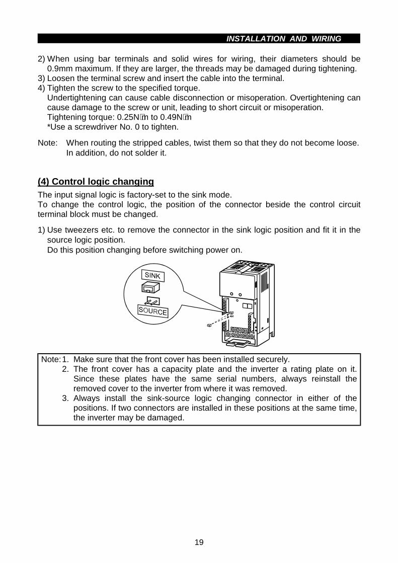
2) When using bar terminals and solid wires for wiring, their diameters should be0.9mm maximum. If they are larger, the threads may be damaged during tightening.
3) Loosen the terminal screw and insert the cable into the terminal.4) Tighten the screw to the specified torque.
Undertightening can cause cable disconnection or misoperation. Overtightening cancause damage to the screw or unit, leading to short circuit or misoperation.Tightening torque: 0.25N⋅m to 0.49N⋅m*Use a screwdriver No. 0 to tighten.
Note: When routing the stripped cables, twist them so that they do not become loose.In addition, do not solder it.
(4) Control logic changingThe input signal logic is factory-set to the sink mode.To change the control logic, the position of the connector beside the control circuitterminal block must be changed.
1) Use tweezers etc. to remove the connector in the sink logic position and fit it in thesource logic position.Do this position changing before switching power on.
Note:1. Make sure that the front cover has been installed securely.2. The front cover has a capacity plate and the inverter a rating plate on it.
Since these plates have the same serial numbers, always reinstall theremoved cover to the inverter from where it was removed.
3. Always install the sink-source logic changing connector in either of thepositions. If two connectors are installed in these positions at the same time,the inverter may be damaged.
INSTALLATION AND WIRING
20
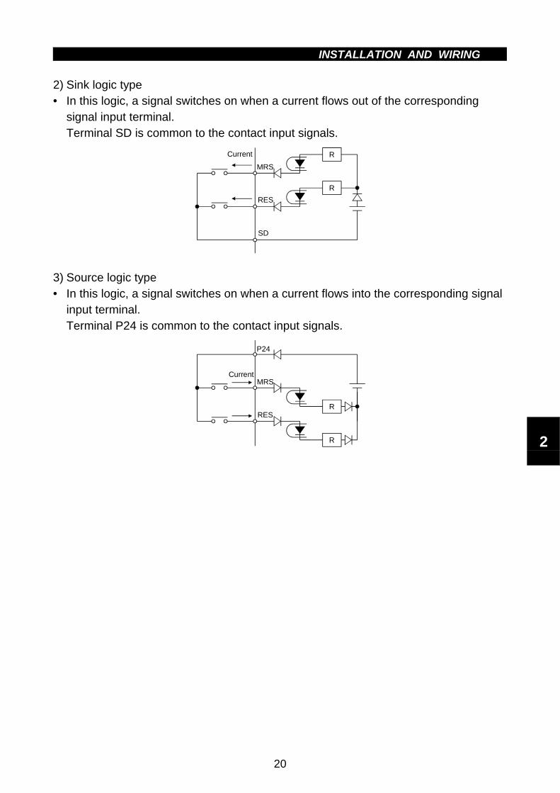
2) Sink logic type• In this logic, a signal switches on when a current flows out of the corresponding
signal input terminal.Terminal SD is common to the contact input signals.
Current
MRS
RES
R
R
SD
3) Source logic type• In this logic, a signal switches on when a current flows into the corresponding signal
input terminal.Terminal P24 is common to the contact input signals.
CurrentMRS
RES
P24
R
R 2

INSTALLATION AND WIRING
21
2.2.4 DeviceNet communication signal wiring
(1) Terminal block layout
The terminal layout of the inverter's DeviceNet communication signals is as shownbelow.Terminal screw size: M2.5
V+
CAN+
SHLD
CAN-
V-
NC
CAUTIONThe DeviceNet terminal block is hard-wired. It is not removable.
(2) Constructing DeviceNet Drop Cable
Use the DeviceNet drop cable to connect the inverter to the DeviceNet network. Thedrop cable consists of an ODVA-approved "thin" cable and a 6-pin connector to beplugged into the inverter's DeviceNet connector. The ODVA approved wire is a hardwire specification. Recommended parts are:
DeviceNet Thin Cable: Belden part number 3082A or equivalent.
Note: Maximum length of drop cable must not exceed 20 feet.
To Network Trunk Cable DeviceNet Thin
Drop Cable
DeviceNet Cable

INSTALLATION AND WIRING
22
1) Strip off the drop cable sheath about 38mm and remove the shield net. In addition tothe signal and power wires, there is one drain wire made by twisting the shield net.
About 38mm
Drain wire
2) Peel off the aluminum tapes which wraps the signal and power wires and strip theinsulations about 6mm.
About 6mm
REMARKSTo prevent the cable from being disconnected, terminate the cable gently.
3) Connect the drop cable to the DeviceNet connector of the inverter as describedbelow.(a) Insert a flat-blade screwdriver (max. width 3.75mm) into the upper hole of the
connector plug and open the clamp in the lower hole to allow the wire to beinserted.
(b) When connecting the DeviceNet drop cable, insert the signal, wire and drainwires into the corresponding connector holes and tighten the fastening screws tothe corresponding torques. Also, make sure that the colors of the wires are asindicated in the table on the next page.
Recommended tightening torque: 0.22N⋅m to 0.25N⋅m
The DeviceNet connector pin out connections are shown in figure below. Refer to thefollowing table for the pin functions.
V- C- SHC+ V+
Inverter's DeviceNet connector
DeviceNet Thin Drop Cable
NC
Connector Pin Out diagram
2

INSTALLATION AND WIRING
23
Pin Out/FunctionsPin No. Color Name Signal Type
1 Red V+ Power cable positive end (V+)2 White CAN+ Communication data high side (CAN H)3 Bare SHLD Drain4 Blue CAN- Communication data low side (CAN L)5 Black V- Power cable negative end (V-)6 — — —
DeviceNet has a voltage specification of 24VDC for communication and an inputvoltage specification of 11VDC to 25VDC for communication to each device. A 5Vdrop in the system is stipulated for each power supply wire (V+, V-).
Note: Use only pins 1 to 5.The DeviceNet connector of the inverter has a 6-pin socket, but do not connect6 pins.

INSTALLATION AND WIRING
24
(3) Connection to a Network
At this point, the inverter must have been installed correctly with the inverter's nodeaddress set (refer to page 47 for node address setting), and the DeviceNet cableconnected to the inverter.
CAUTIONDo not connect cable to the network until told to do so. To sucessfully connect to aDeviceNet network please follow the below procudures and checks:
1) Check that the inverter power is turned off.
2) Make sure that a terminating resistor is installed at each end of the trunk cable(across CAN(+) and CAN (-)), as shown in the following figure.These resistors must meet the following requirements:
1. R = 121Ω2. 1% metal film3. 0.25W
IBM Compatible
Trunk cable
Drop cable
Connection to a DeviceNet network
Termination resistor(121 )
3) Connect cable to network as follows (this is the cable from the inverter to theDeviceNet network):
(a) If the trunk connector is a DeviceNet sanctioned pluggable or sealed connector,the connection to the active network can be made at any time whether theinverter is on or off. The inverter unit automatically detects when the connectionis completed.
(b) If connecting to the network with free wires, power to the network and invertershould be shut off as a safety precaution in case two or more signal wires areaccidentally shorted together.
4) Check that all connections are completed, and all necessary wires not associatedwith DeviceNet are connected to the inverter unit as required by the application.
2

INSTALLATION AND WIRING
25
(4) LED Status Indicator
The LED Status indicator provides information on the status of operation of theinverter. The status information is shown in the below table. The indicator has fivestates; Off, Blinking Green, Steady Green, Blinking Red, and Steady Red.
After connecting the drop cable to the trunk of the active network, observe thecondition of the Status LED. The inverter unit uses the Combined Module/Networkstatus LED scheme described in the DeviceNet communications standard.
LED Status indication
LED CONDITION STATE OF SYSTEM NOTEInverter power offNetwork power on
Turn the inverter power on. The inverter willthen complete duplicate node address test.
Off
Power on the inverterwhen network Power isoff.
Turn the network power on. The inverter unitwill then complete duplicate node address test.
Blinking Green Connection not yetestablished by master
Though the inverter power is on and it hasbeen confirmed that there is no same nodeaddress, the master has not yet established acommunication link.
Steady Green Network and inverterpower on, connectionestablished by master
A master device on the network has designatedthe inverter unit for communications. The LEDalso holds this state during communication.
Blinking Red Connection time-out The master station has selected this inverterunit for communication (LED is green).However, no response is given within thewaiting time (Note) set in EPR. Check themaster for disconnection from the network.
Steady Red Critical link failure Failed communication device• Duplicate station number• Network power off• Cable from option unit to network not
connected or severed.• Inverter unit is only node on network• Network damaged
Must cycle power to recover from this fault.
Note: Time Limit = 4 × EPR (EXPECTED PACKET RATE)It should be noted that this EPR is the EPR set by the DeviceNet master. Thisdoes not refer to the bit setting of EPR in Pr. 347.

INSTALLATION AND WIRING
26
2.2.5 Connection to the PU connector
(1) When connecting the parameter unit using a cable
Use the option FR-CB2# or the following connector and commercially available cable:
<Connection cable>! Connector : RJ45 connector
Exampl: 5-554720-3, Tyco Electronics Corporation! Cable : Cable conforming to EIA568 (e.g. 10BASE-T cable)
Example: SGLPEV 0.5mm×4P (Twisted pair cable, 4 pairs),MITSUBISHI CABLE INDUSTRIES, LTD.
<Maximum wiring length>! Parameter unit (FR-PU04): 20m
(2) For RS-485 communication
With the accessory cover disconnected, the PUconnector can be used for communicationoperation from a personal computer etc.When the PU connector is connected with apersonal, FA or other computer by acommunication cable, a user program allows theinverter to be run and monitored and the parametervalues to be read and written.
<PU connector pin-outs>Viewed from the inverter (receptacle side) front
8) to 1)
1) SG2) P5S3) RDA4) SDB
5) SDA6) RDB7) SG8) P5S
Note:1. Do not connect the PU connector to a computer's LAN board, FAX modemsocket or telephone modular connector. Otherwise, the product may bedamaged due to electrical specification differences.
2. Pins 2) and 8) (P5S) provide power to the parameter unit. Do not use thesepins for RS-485 communication.
2

INSTALLATION AND WIRING
27
<System configuration examples>
1) When a computer having a RS-485 interface is used with several inverters
PU connector(Note1)
Computer
RS-485 interface/terminalComputer
10BASE-T cable (Note 2)
Distributionterminal
Station 1
Inverter
Station 2
Inverter
Station n
Inverter
Terminationresistor
PU connector(Note1)
PU connector(Note1)
Use the connectors and cables which are available on the market.Note: 1. Connector: RJ45 connector
Example: 5-554720-3, Tyco Electronics Corporation2. Cable : Cable conforming to EIA568 (such as 10BASE-T cable)
Example: SGLPEV 0.5mm × 4P (Twisted pair cable, 4 pairs),Mitsubishi Cable Industries, Ltd.(Do not use pins 2) and 8) (P5S).)
2) When a computer having a RS-232C interface is used with inverters
Computer
RS-232CconnectorRS-232Ccable
RS-485terminal
Max. 15m
Converter*
Terminationresistor
Distributionterminal
*Commercially available converter is required. (Note 3)10BASE-T cable (Note 2)
PU connector(Note1)
Station 1
Inverter
PU connector(Note1)
Station 2
Inverter
PU connector(Note1)
Station n
Inverter
Use the connectors, cables and converter which are available on themarket.
Note:1. Connector: RJ45 connectorExample: 5-554720-3, Tyco Electronics Corporation
2. Cable : Cable conforming to EIA568 (such as 10BASE-T cable)Example: SGLPEV 0.5mm × 4P (Twisted pair cable, 4 pairs),Mitsubishi Cable Industries, Ltd.(Do not use pins 2) and 8) (P5S).)
3.*Commercially available converter examplesModel: FA-T-RS40ConverterMitsubishi Electric Engineering Co., Ltd.

INSTALLATION AND WIRING
28
<Wiring methods>1) Wiring of one RS-485 computer and one inverter
SDB
SDA
RDB
RDA
FG
SG
CSB
CSA
RSB
RSARDB
RDA
SDB
SDA
SG
(Note 1)
Computer Side Terminals
Signal name Description
Receive data
Receive data
Send data
Send dataRequest to send
Request to send
Clear to send
Clear to send
Signal ground
Frame ground
Cable connection and signal direction
10 BASE-T Cable
InverterPU connector
0.3mm or more2
2) Wiring of one RS-485 computer and "n" inverters (several inverters)
SDB
SDA
RDB
RDA
FG
SG
CSB
CSA
RSB
RSA
(Note 1)
SG
RD
B
RD
A
SD
B
SD
A
SG
RD
B
RD
A
SD
B
SD
A
SG
RD
B
RD
A
SD
B
SD
A
Computer
Station 1 Station 2 Station n
Inverter Inverter Inverter
Terminationresistor(Note 2)
Cable connection and signal direction
10 BASE-T Cable
Note:1. Make connections in accordance with the instruction manual of thecomputer used.Fully check the terminal numbers of the computer as they differ betweenmodels.
2. There may be the influence of reflection depending on the transmissionspeed and/or transmission distance. If this reflection hinderscommunication, provide a termination resistor. If the PU connector is usedto make a connection, use the distributor as a termination resistor cannot befitted.Connect the termination resistor to only the inverter remotest from thecomputer. (Termination resistor: 100Ω)
2

INSTALLATION AND WIRING
29
2.2.6 Connection of stand-alone option units
The inverter accepts a variety of stand-alone option units as required.Incorrect connection will cause inverter damage or an accident. Connect and operatethe option unit carefully in accordance with the corresponding option unit manual.
(1) Connection of the dedicated external brake resistor (option)(Cannot be connected to 0.1K and 0.2K)
Connect a brake resistor across terminals P (+) and PR. Connect a dedicated brakeresistor only.(For the positions of terminals P (+) and PR, refer to the terminal block layout (page16).)
PR
P
Brake resistor
(+) PRBrake resistor
P1N
FR-E520-0.4KND, 0.75KND, 5.5KND, 7.5KND FR-E520-1.5KND to 3.7KND
P(+)
INSTALLATION AND WIRING
30
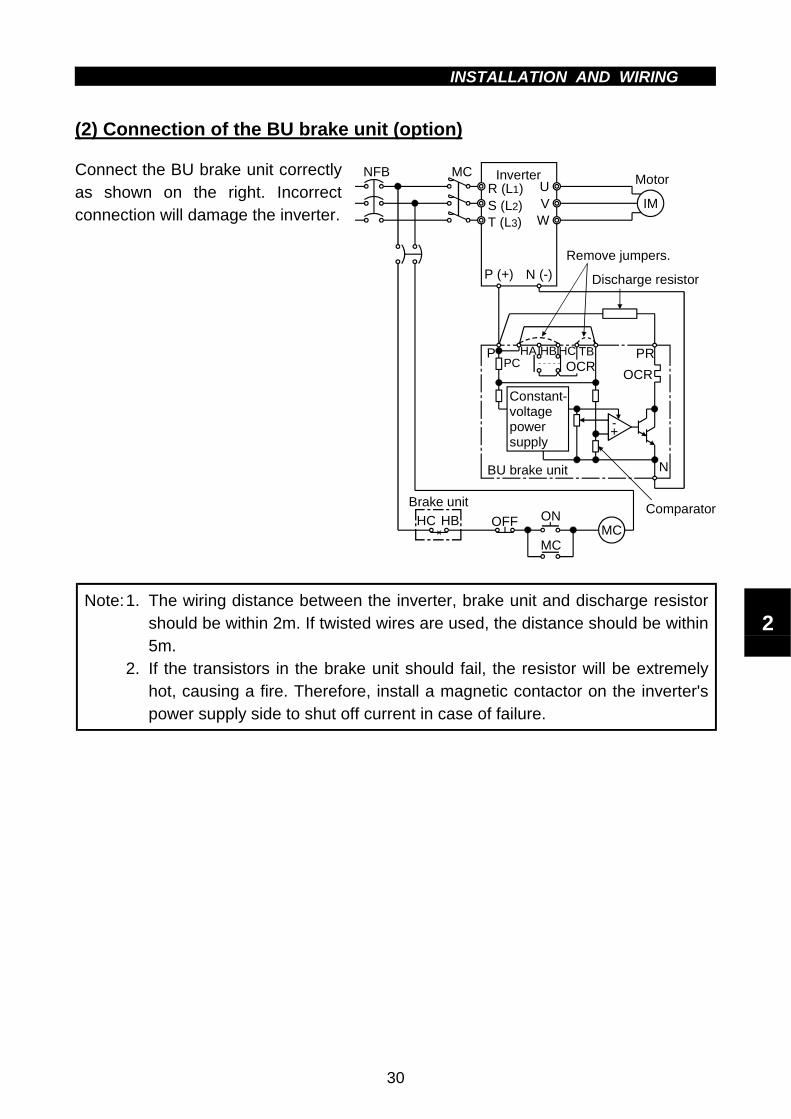
(2) Connection of the BU brake unit (option)
Connect the BU brake unit correctlyas shown on the right. Incorrectconnection will damage the inverter.
MCR (L1)S (L2)T (L3)
UV
W
Motor
IM
Inverter
HCHBHA TB
HC HB ONBrake unit
MCMC
OFF
P (+) N (-)
POCR
Discharge resistor
Remove jumpers.
PR
OCR
-+
BU brake unit N
NFB
Constant-voltage power supply
Comparator
PC
Note:1. The wiring distance between the inverter, brake unit and discharge resistorshould be within 2m. If twisted wires are used, the distance should be within5m.
2. If the transistors in the brake unit should fail, the resistor will be extremelyhot, causing a fire. Therefore, install a magnetic contactor on the inverter'spower supply side to shut off current in case of failure.
2

INSTALLATION AND WIRING
31
(3) Connection of the FR-HC high power factor converter (option unit)When connecting the high power factor converter (FR-HC) to suppress powerharmonics, wire as shown below. Wrong connection will damage the high power factorconverter and inverter.
Inverter(FR-E500)
IM
High power factor converter
(FR-HC)External box
(FR-HCB)
Reactor 2(FR-HCL02)
R (L1)
Resistor
Reactor 1(FR-HCL01)
Power supply
Filter capacitor
Phase detection
S (L2)T (L3)
P (+)N (-)MRSRESSD
UVW
PN
RDYRSO
SERST
R4S4T4
R3S3T3
R3
S3T3MC
R2S2T2
R2S2T2
RST
MCNFB
MC1MC2
Motor
Resistor MC1MC2
R4S4T4
Note:1. The power input terminals R, S, T (L1, L2, L3) must be open.Incorrect connection will damage the inverter. Reverse polarity of terminalsN (−), P (+) will damage the inverter.
2. The voltage phases of terminals R, S, T (L1, L2, L3) and terminals R4, S4,T4 must be matched before connection.
3. If the load capacity is less than half of the high power factor convertercapacity, satisfactory harmonic suppression effects cannot be produced.
(4) Connection of the power factor improving DC reactor (option)
Connect the FR-BEL powerfactor improving DC reactorbetween terminals P1-P (+). Inthis case, the jumper connectedacross terminals P1-P (+) mustbe removed. Otherwise, thereactor will not function.
P1 P
FR-BEL
Remove the jumper.
P1
P
FR-BEL
Remove the jumper.
FR-E520-1.5KND to 3.7KND<Connection method> FR-E520-0.1KND to 0.75KND,
5.5KND,7.5KND
PRN(-) (+) (+)
Note:1. The wiring distance should be within 5m.2. The size of the cables used should be equal to or larger than that of the
power supply cables (R (L1), S (L2), T (L3)).

INSTALLATION AND WIRING
32
2.2.7 Design information
1) Provide electrical and mechanical interlocks for MC1 and MC2 which are used forcommercial power supply-inverter switch-over.When there is a commercial power supply-inverter switch-over circuit as shownbelow, the inverter will be damaged by leakage current from the power supply due toarcs generated at the time of switch-over or chattering caused by a sequence error.
2) If the machine must not be restarted when power is restored after a power failure,provide a magnetic contactor in the inverter's primary circuit and also make up asequence which will not switch on the start signal.If the start signal (start switch) remains on after a power failure, the inverter willautomatically restart as soon as the power is restored.
3) Since the input signals to the control circuit are on a low level, use two or moreparallel micro signal contacts or a twin contact for contact inputs to prevent a contactfault.
4) Do not apply a large voltage to the contact input terminals (e.g. STF) of the controlcircuit.
5) Always apply a voltage to the alarm output terminals (A, B, C) via a relay coil, lampetc.
6) Make sure that the specifications and rating match the system requirements.
1) Commercial power supply-inverterswitch-over
UVW
R (L1)S (L2)T (L3)
IMPower supply
InverterLeakage current
MC2
MC1
Interlock
3) Low-level signal contacts
Low-level signal contacts Twin contact
2

2.3 Other WiringINSTALLATION AND WIRING
33
2.3 Other Wiring
2.3.1 Power supply harmonics
Power supply harmonics may be generated from the converter section of the inverter,affecting the power supply equipment, power capacitor, etc. Power supply harmonicsare different in generation source, frequency band and transmission path from radiofrequency (RF) noise and leakage currents. Take the following counter measures.
"""" The differences between harmonics and RF noises are indicated below:
Item Harmonics RF Noise
FrequencyNormally 40th to 50thdegrees or less, (up to 3kHzor less)
High frequency (several 10kHz to MHzorder)
EnvironmentTo wire paths, powerimpedance
Across spaces, distance, laying paths
Quantitativeunderstanding
Logical computation ispossible
Occurs randomly, quantitativeunderstanding is difficult.
Generated amountApproximately proportionalto load capacity
According to current fluctuation rate(larger with faster switching)
Immunity of affecteddevice
Specified in standards foreach device.
Differs according to maker's devicespecifications.
Examples ofsafeguard
Install a reactor. Increase the distance.
"""" Countermeasures
The harmonic current generated from theinverter to the power supply differsaccording to various conditions such as thewiring impedance, whether a power factorimproving reactor is used or not, and outputfrequency and output current on load side.For the output frequency and output current,the adequate method is to obtain themunder rated load at the maximum operatingfrequency.
Note: A power factor improving capacitor and surge suppressor on the inverter'soutput side may overheat or be damaged due to the harmonics of the inverteroutput. Also, when an overcurrent flows in the inverter, the overcurrentprotection is activated. Hence, when the motor is driven by the inverter, donot install a capacitor or surge suppressor on the inverter's output side. Toimprove the power factor, insert a power factor improving reactor in theinverter's input or DC circuit. For details, refer to the FR-A500/E500 seriestechnical information.
NFB
IM
Power factor improving AC reactor
Inve
rte
r
Power factor improving DC reactor
Motor
Do not insert power factor improving capacitor

INSTALLATION AND WIRING
34
2.3.2 Japanese harmonic suppression guideline
Harmonic currents flow from the inverter to a power receiving point via a powertransformer. The harmonic suppression guideline was established to protect otherconsumers from these outgoing harmonic currents.1) "Harmonic suppression guideline for household appliances and general-purpose
products"The "harmonic suppression guideline for household appliances and general-purposeproducts" issued by ex-Ministry of International Trade and Industry (present Ministryof Economy, Trade and Industry) in September, 1994 applies to the 3.7K and lessmodels. By installing the FR-BEL or FR-BAL power factor improving reactor, inverterscomply with the "haramonic suppression techniques for transistorized inverters (inputcurrent 20A or less)" established by the Japan Electrical Manufacturers′ Association.Therefore, install the optional reactor for the 3.7kW or less inverter.
2) "Harmonic suppression guideline for specific consumers"This guideline sets forth the maximum values of harmonic currents outgoing from ahigh-voltage or specially high-voltage consumer who will install, add or renewharmonic generating equipment. If any of the maximum values is exceeded, thisguideline requires that consumer to take certain suppression measures.
Table 1 Maximum Values of Outgoing Harmonic Currents per 1kW Contract Power
Received Power Voltage 5th 7th 11th 13th 17th 19th 23rd Over23rd
6.6kV 3.5 2.5 1.6 1.3 1.0 0.9 0.76 0.7022 kV 1.8 1.3 0.82 0.69 0.53 0.47 0.39 0.3633 kV 1.2 0.86 0.55 0.46 0.35 0.32 0.26 0.24
(1) Application of the harmonic suppression guideline for specificconsumers
Not more thanreference capacity
New installation/addition/renewal of equipment
Calculation of equivalentcapacity sum
Sum of equivalentcapacities
Over referencecapacity
Calculation of outgoing harmonic current
Is outgoing harmoniccurrent equal to or lowerthan maximum value?
Not more than maximum value
Harmonic suppression technique is not required.
Over maximum value
Harmonic suppressiontechnique is required.
2

INSTALLATION AND WIRING
35
Table 2 Conversion Factors for FR-E500 Series
Class Circuit Type Conversion Factor (Ki)Without reactor K31 = 3.4With reactor (AC side) K32 = 1.8With reactor (DC side) K33 = 1.8
33-phase bridge(Capacitor-smoothed)
With reactors (AC, DC sides) K34 = 1.4
5 Self-exciting 3-phase bridgeWhen high power factorconverter is used
K5 = 0
Table 3 Equivalent Capacity Limits
Received Power Voltage Reference Capacity6.6kV 50 kVA22/33 kV 300 kVA66kV or more 2000 kVA
Table 4 Harmonic Contents (Values at the fundamental current of 100%)
Reactor 5th 7th 11th 13th 17th 19th 23rd 25thNot used 65 41 8.5 7.7 4.3 3.1 2.6 1.8Used (AC side) 38 14.5 7.4 3.4 3.2 1.9 1.7 1.3Used (DC side) 30 13 8.4 5.0 4.7 3.2 3.0 2.2Used (AC, DC sides) 28 9.1 7.2 4.1 3.2 2.4 1.6 1.4
1) Calculation of equivalent capacity (P0) of harmonic generating equipmentThe "equivalent capacity" is the capacity of a 6-pulse converter converted from thecapacity of consumer's harmonic generating equipment and is calculated with thefollowing equation. If the sum of equivalent capacities is higher than the limit inTable 3, harmonics must be calculated with the following procedure:
P0=Σ (Ki× Pi) [kVA]Ki : Conversion factor (refer to Table 2)Pi : Rated capacity of harmonic
generating equipment* [kVA]i : Number indicating the conversion
circuit type
*Rated capacity: Determined by the capacityof the applied motor and found in Table 5. Itshould be noted that the rated capacityused here is used to calculate a generatedharmonic amount and is different from thepower supply capacity required for actualinverter drive.
2) Calculation of outgoing harmonic currentOutgoing harmonic current = fundamental wave current (value converterd from received
power voltage) × operation ratio × harmonic content• Operation ratio: Operation ratio = actual load factor × operation time ratio
during 30 minutes• Harmonic content: Found in Table 4.

INSTALLATION AND WIRING
36
Table 5 Rated Capacities and Outgoing Harmonic Currents for Inverter Drive
RatedCurrent [A]
Fundamental Wave Current Converted from 6.6kV(No reactor, 100% operation ratio)Applied
Motor(kW) 200V
6.6kVEquivalent ofFundamentalWave Current
(mA)
RatedCapacity
(kVA) 5th 7th 11th 13th 17th 19th 23rd 25th
0.41.61
(Note)49 0.57 31.85 20.09 4.165 3.773 2.107 1.519 1.274 0.882
0.752.74
(Note)83 0.97 53.95 34.03 7.055 6.391 3.569 2.573 2.158 1.494
1.55.50
(Note)167 1.95 108.6 68.47 14.20 12.86 7.181 5.177 4.342 3.006
2.27.93
(Note)240 2.81 156.0 98.40 20.40 18.48 10.32 7.440 6.240 4.320
3.713.0
(Note)394 4.61 257.1 161.5 33.49 30.34 16.94 12.21 10.24 7.092
5.5 19.1 579 6.77 376.1 237.4 49.22 44.58 24.90 17.95 15.05 10.427.5 25.6 776 9.07 504.4 318.2 65.96 59.75 33.37 24.06 20.18 13.97
Note: When a motor of 3.7kW or less capacity is driven by a transistorized inverter ofmore than 3.7kW. For example, when a 3.7kW or less motor is driven by a5.5kW transistorized inverter, the transistorized inverter is not the target of thehousehold appliances/general-purpose products guideline, but because theymust be included in the calculation of the harmonic current of the guideline, thefundamental wave input currents are indicated.
3) Harmonic suppression technique requirementIf the outgoing harmonic current is higher than; maximum value per 1kW (contractpower) × contract power, a harmonic suppression technique is required.
4) Harmonic suppression techniquesNo. Item Description
1Reactor installation(ACL, DCL)
Install a reactor (ACL) in the AC side of the inverter or a reactor(DCL) in its DC side or both to suppress outgoing harmoniccurrents.
2
High power factorconverter(FR-HC)
The converter circuit is switched on-off to convert an inputcurrent waveform into a sine wave, suppressing harmoniccurrents substantially. The high power factor converter (FR-HC)is used with the standard accessory.
3Installation of powerfactor improvingcapacitor
When used with a series reactor, the power factor improvingcapacitor has an effect of absorbing harmonic currents.
4Transformer multi-phase operation
Use two transformers with a phase angle difference of 30° as in-∆, ∆-∆ combination to provide an effect corresponding to 12
pulses, reducing low-degree harmonic currents.
5AC filter A capacitor and a reactor are used together to reduce
impedances at specific frequencies, producing a great effect ofabsorbing harmonic currents.
6
Passive filter(Active filter)
This filter detects the current of a circuit generating a harmoniccurrent and generates a harmonic current equivalent to adifference between that current and a fundamental wave currentto suppress a harmonic current at a detection point, providing agreat effect of absorbing harmonic currents.
2

INSTALLATION AND WIRING
37
2.3.3 Inverter-generated noise and reduction techniques
Some noises enter the inverter causing it to incorrectly operate, and others areradiated by the inverter causing misoperation of peripheral devices. Though theinverter is designed to be insusceptible to noise, it handles low-level signals, so itrequires the following basic measures to be taken. Also, since the inverter chops theoutput at high carrier frequencies, it could generate noise. If these noises causeperipheral devices to misoperate, measures should be taken to suppress noise. Themeasures differ slightly depending on noise propagation paths.
1) Basic measures! Do not run the power cables (I/O cables) and signal cables of the inverter in
parallel with each other and do not bundle them.! Use twisted shield cables for the detector connecting and control signal cables
and connect the sheathes of the shield cables to terminal SD.! Ground the inverter, motor, etc. at one point.
2) Measures against noise which enters and causes misoperation of the inverterWhen devices which generate noise (devices which use magnetic contactors,magnetic brakes, many relays, for example) are installed near the inverter, theinverter may misoperate due to noise. The following measures must be taken:! Provide surge suppressors for devices that generate noise to suppress noise.! Fit data line filters (refer to page 40) to signal cables.! Ground the shields of the detector connection and control signal cables with cable
clamp metal.

INSTALLATION AND WIRING
38
3) Measures against noises which are radiated by the inverter causing misoperation ofperipheral devices.Inverter-generated noises are largely classified into those radiated by the cablesconnected to the inverter and inverter main circuit (I/O), those electromagneticallyand electrostatically inducted to the signal cables of the peripheral devices close tothe main circuit power supply, and those transmitted through the power supplycables.
Inverter-generated noise
Air-propagated noise
$$$Path 3)
$$$Path 2)
$$$Path 1)
$$$Path 4), 5)
$$$Path 6)
$$$Path 8)
$$$Path 7)
Magnetic induc-tion noise
Static induction noise
Cable Propaga-ted noise
Noise directly radiated by inverter
Noise radiated by power cables
Noise radiated by motor cables
Noise propagated through power cables
Leakage noise from groundcable due to leakage current
Instrument
ReceiverInve-rter
IM
Sensor power supply
Motor
Telephone
Sensor
7) 2)
1)
3)4)
5)
7)
2)6)
3)
8)
2

INSTALLATION AND WIRING
39
Noise Path Measures
1), 2), 3)
When devices which handle low-level signals and are susceptible tomisoperation due to noise (such as instruments, receivers and sensors)are installed near the inverter and their signal cables are contained in thesame panel as the inverter or are run near the inverter, the devices maybe misoperated by air-propagated noise and the following measures mustbe taken:(1) Install easily affected devices as far away as possible from the
inverter.(2) Run easily affected signal cables as far away as possible from the
inverter.(3) Do not run the signal cables and power cables (inverter I/O cables) in
parallel with each other and do not bundle them.(4) Insert line noise filters onto I/O and radio noise filters into inputs to
suppress cable-radiated noises.(5) Use shielded cables for signal cables and power cables and run them
in individual metal conduits to further reduce effects.
4), 5), 6)
When the signal cables are run in parallel with or bundled with the powercables, magnetic and static induction noises may be propagated to thesignal cables causing misoperation of the devices and the followingmeasures must be taken:(1) Install easily affected devices as far away as possible from the
inverter.(2) Run easily affected signal cables as far away as possible from the
inverter.(3) Do not run the signal cables and power cables (inverter I/O cables) in
parallel with each other and do not bundle them.(4) Use shielded cables for signal cables and power cables and run them
in individual metal conduits to further reduce effects.
7)
When the power supplies of the peripheral devices are connected to thepower supply of the inverter within the same line, inverter-generated noisemay flow back through the power supply cables causing misoperation ofthe devices and the following measures must be taken:(1) Install the radio noise filter (FR-BIF) to the power cables (input cables)
of the inverter.(2) Install the line noise filter (FR-BLF, FR-BSF01) to the power cables
(I/O cables) of the inverter.
8)
When a closed loop circuit is formed by connecting the peripheral devicewiring to the inverter, leakage current may flow through the ground cableof the inverter causing misoperation of the device. In such a case,disconnection of the ground cable of the device may cause the device tooperate properly.
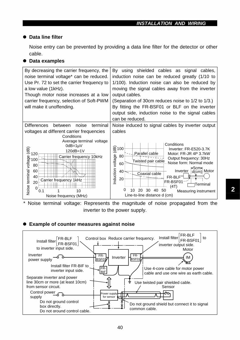
INSTALLATION AND WIRING
40
"""" Data line filter
Noise entry can be prevented by providing a data line filter for the detector or othercable.
"""" Data examples
By decreasing the carrier frequency, thenoise terminal voltage* can be reduced.Use Pr. 72 to set the carrier frequency toa low value (1kHz).Though motor noise increases at a lowcarrier frequency, selection of Soft-PWMwill make it unoffending.
By using shielded cables as signal cables,induction noise can be reduced greatly (1/10 to1/100). Induction noise can also be reduced bymoving the signal cables away from the inverteroutput cables.(Separation of 30cm reduces noise to 1/2 to 1/3.)By fitting the FR-BSF01 or BLF on the inverteroutput side, induction noise to the signal cablescan be reduced.
Differences between noise terminalvoltages at different carrier frequencies
0
20
40
60
80
100
120
0.1 1 10Noise frequency (MHz)N
ois
e te
rmin
al v
olta
ge
(dB
)
ConditionsAverage terminal voltage 0dB=1µV 120dB=1V
Carrier frequency 10kHz
Carrier frequency 1kHz
Noise induced to signal cables by inverter outputcables
5cm
Line-to-line distance d (cm)
20
40
60
80
100
100 20 30 40 50
Ind
uctio
n vo
ltage
(d
B)
d(cm) Motor
Measuring instrument
Terminal
Inverter
FR-BLFFR-BSF01
(4T)
Conditions Inverter: FR-E520-3.7K Motor: FR-JR 4P 3.7kW Output frequency: 30Hz Noise form: Normal mode
Parallel cable
Twisted pair cable
Coaxial cable
* Noise terminal voltage: Represents the magnitude of noise propagated from theinverter to the power supply.
"""" Example of counter measures against noise
Inverter
FR-BIF
Sensor
Use 4-core cable for motor power cable and use one wire as earth cable.
Power supply for sensor
Use twisted pair shielded cable.
Inverter power supply
Control power supply
Do not ground shield but connect it to signal common cable.
Do not ground control box directly.Do not ground control cable.
Separate inverter and power line 30cm or more (at least 10cm) from sensor circuit.
Install filter FR-BIF to inverter input side.
Control box Reduce carrier frequency.
Motor
IMFR-BSF01
FR-BSF01
FR-BLFFR-BSF01
Install filter
to inverter input side.
FR-BLFFR-BSF01
Install filter to
inverter output side.
2
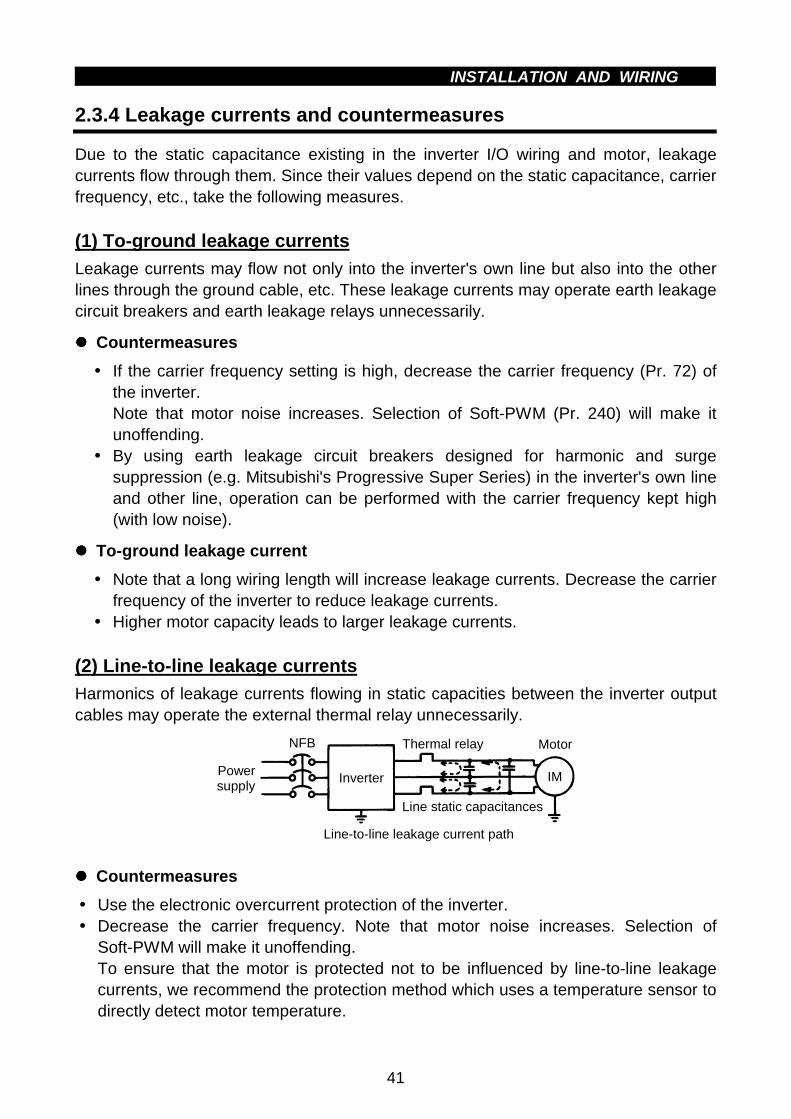
INSTALLATION AND WIRING
41
2.3.4 Leakage currents and countermeasures
Due to the static capacitance existing in the inverter I/O wiring and motor, leakagecurrents flow through them. Since their values depend on the static capacitance, carrierfrequency, etc., take the following measures.
(1) To-ground leakage currents
Leakage currents may flow not only into the inverter's own line but also into the otherlines through the ground cable, etc. These leakage currents may operate earth leakagecircuit breakers and earth leakage relays unnecessarily.
"""" Countermeasures
! If the carrier frequency setting is high, decrease the carrier frequency (Pr. 72) ofthe inverter.Note that motor noise increases. Selection of Soft-PWM (Pr. 240) will make itunoffending.
! By using earth leakage circuit breakers designed for harmonic and surgesuppression (e.g. Mitsubishi's Progressive Super Series) in the inverter's own lineand other line, operation can be performed with the carrier frequency kept high(with low noise).
"""" To-ground leakage current
! Note that a long wiring length will increase leakage currents. Decrease the carrierfrequency of the inverter to reduce leakage currents.
! Higher motor capacity leads to larger leakage currents.
(2) Line-to-line leakage currents
Harmonics of leakage currents flowing in static capacities between the inverter outputcables may operate the external thermal relay unnecessarily.
InverterPower supply
IM
Thermal relay
Line static capacitances
NFB
Line-to-line leakage current path
Motor
"""" Countermeasures
! Use the electronic overcurrent protection of the inverter.! Decrease the carrier frequency. Note that motor noise increases. Selection of
Soft-PWM will make it unoffending.To ensure that the motor is protected not to be influenced by line-to-line leakagecurrents, we recommend the protection method which uses a temperature sensor todirectly detect motor temperature.

INSTALLATION AND WIRING
42
2.3.5 Peripheral devices
(1) Selection of peripheral devicesCheck the capacity of the motor to be used with the inverter you purchased.Appropriate peripheral devices must be selected according to the capacity.Refer to the following list and prepare appropriate peripheral devices:
No-Fuse Breaker (NFB) or Earth Leakage Circuit
Breaker (NV) (Note 5)
Magnetic Contactor
(MC)Inverter Type
Motor
Output
(kW)
Power
Supply
Capacity
(kVA)Standard
With power factor
improving reactorA B C
FR-E520-0.1K 0.1 0.4 30AF 5A 30AF 5A S-N11 S-N18 S-N20
FR-E520-0.2K 0.2 0.8 30AF 5A 30AF 5A S-N18 S-N20 S-N20
FR-E520-0.4K 0.4 1.5 30AF 5A 30AF 5A S-N18 S-N21 S-N21
FR-E520-0.75K 0.75 2.5 30AF 10A 30AF 10A S-N18 S-N21 S-N21
FR-E520-1.5K 1.5 4.5 30AF 15A 30AF 15A S-N21 S-N25 S-N50
FR-E520-2.2K 2.2 5.5 30AF 20A 30AF 15A S-N11,S-N12
FR-E520-3.7K 3.7 9 30AF 30A 30AF 30A S-N20
FR-E520-5.5K 5.5 12 50AF 50A 50AF 40A S-N25
Thre
e-p
hase
200V
FR-E520-7.5K 7.5 17 100AF 60A 50AF 50A S-N35
Note:1. Select the type of the no-fuse breaker(NFB) in response to the powersupply capacity.
2. The power supply cable size of themotor indicated assumes that itslength is 20m.
3. The inverter input side magneticcontactor to be chosen differsbetween the applicable ranges A, Band C shown on the right, dependingon the power supply capacity and
Power factor improvingAC reactorrange
AB
C
Note: Power supply used has the above recommended size.
0 10 20 Wiring length(m)
50
500
Pow
er s
uppl
y ca
paci
ty(k
VA
)
wiring length. For the FR-E520-0.4KND to 1.5KND choose the S-N10 whenthe power factor improving reactor (FR-BEL or FR-BAL) is used.
4. When the inverter capacity is greater than the motor capacity, choose thebreaker and magnetic contactor in accordance with the inverter type andchoose the cables and power factor improving reactor in accordance withthe motor output.
5. For installations in the United States or Canada, the circuit breaker must beinverse time or instantaneous trip type.
"""" Installation and selection of no-fuse breakerInstall a no-fuse breaker (NFB) in the power supply side for protection of the inverter'sprimary wiring. Refer to the previous table and choose the NFB according to theinverter's power supply side power factor (which changes with the power supplyvoltage, output frequency and load). Especially for a completely electromagnetic typeNFB, the one with a larger capacity must be selected since its operationalcharacteristics change with harmonic currents. (Check the data of the correspondingbreaker for confirmation.) Also the earth leakage circuit breaker used should be ourproduct durable against harmonics/surges (such as the Progressive Super Series).
2
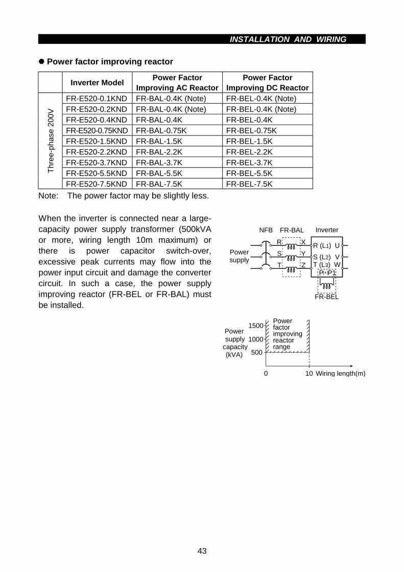
INSTALLATION AND WIRING
43
"""" Power factor improving reactor
Inverter ModelPower Factor
Improving AC ReactorPower Factor
Improving DC ReactorFR-E520-0.1KND FR-BAL-0.4K (Note) FR-BEL-0.4K (Note)FR-E520-0.2KND FR-BAL-0.4K (Note) FR-BEL-0.4K (Note)FR-E520-0.4KND FR-BAL-0.4K FR-BEL-0.4KFR-E520-0.75KND FR-BAL-0.75K FR-BEL-0.75KFR-E520-1.5KND FR-BAL-1.5K FR-BEL-1.5KFR-E520-2.2KND FR-BAL-2.2K FR-BEL-2.2KFR-E520-3.7KND FR-BAL-3.7K FR-BEL-3.7KFR-E520-5.5KND FR-BAL-5.5K FR-BEL-5.5KT
hree
-pha
se 2
00V
FR-E520-7.5KND FR-BAL-7.5K FR-BEL-7.5K
Note: The power factor may be slightly less.
When the inverter is connected near a large-capacity power supply transformer (500kVAor more, wiring length 10m maximum) orthere is power capacitor switch-over,excessive peak currents may flow into thepower input circuit and damage the convertercircuit. In such a case, the power supplyimproving reactor (FR-BEL or FR-BAL) mustbe installed.
NFB InverterFR-BAL
Powersupply
R
S
T Z
Y
X R (L1)
S (L2)T (L3)
U
VW
P P1
FR-BEL
(+)
Power factor improving reactorrange
0 10
500
1500
1000Power supplycapacity(kVA)
Wiring length(m)

INSTALLATION AND WIRING
44
(2) Selecting the rated sensitivity current for the earth leakage circuit breaker
When using the earth leakage circuit breaker with the inverter circuit, select its ratedsensitivity current as follows, independently of the PWM carrier frequency:
Leakage current example of 3-phase induction motor during commercial power supply operation (200V 60Hz)
Cable size (mm2)
550.1
1.5 3.72.2
7.5 15 2211
3730 45
0.20.30.50.71.0
2.0
5.5 18.5
Leaka
ge c
urr
ent
(mA
)
Motor capacity (kW)
Example of leakage current per 1km incable path during commercial powersupply operation when the CV cable isrouted in metal conduit(200V 60Hz)
020406080
100120
3.55.5
8 2230
3860
80100
150Leaka
ge c
urr
ent
(mA
)
2 14
! Progressive Super Series (Type SP, CF, SF, CP)Rated sensitivity current: I∆n ≥ 10×(lg1+Ign+lg2+lgm)
! Conventional NV series (Type CA, CS, SS produced prior to '91)Rated sensitivity current: I∆n ≥ 10×lg1+lgn+3×(lg2+lgm)
lg1, lg2 : Leakage currents of cable path during commercial power supply operationlgn* : Leakage current of noise filter on inverter input sidelgm : Leakage current of motor during commercial power supply operation
<Example>
Ig1 Ign Ig2 Igm
5.5mm2 × 5m 5.5mm2 × 70m
IM 3φ200V 2.2kW
Inverter
NV Noise filter
Note:1. The earth leakage circuit breaker should be installed to the primary (powersupply) side of the inverter.
2. Ground fault in the secondary side of the inverter can be detected at therunning frequency of 120Hz or lower.
3. In the connection neutral point grounded system, the sensitivity currentbecomes worse for ground faults in the inverter secondary side. Hence, theprotective grounding of the load equipment should be class C grounding (10Ωor less).
4. When the breaker is installed in the secondary side of the inverter, it may beunnecessarily operated by harmonics if the effective value is less than therating. In this case, do not install the breaker since the eddy current andhysteresis loss increase and the temperature rises.
* Note the leakage current value of the noise filter installed on the inverter inputside.
2

INSTALLATION AND WIRING
45
Progressive Super Series(Type SP, CF, SF,CP)
Conventional NV(Type CA, CS, SS)
5mLeakage current (Ig1) (mA) 33 ×
1000m = 0.17
Leakage current (Ign) (mA) 0 (without noise filter)70m
Leakage current (Ig2) (mA) 33 ×1000m
= 2.31
Motor leakagecurrent (Igm) (mA)
0.18
Total leakage current (mA) 2.66 7.64Rated sensitivity current
( ≥ Ig × 10) (mA)30 100

INSTALLATION AND WIRING
46
2.3.6 Instructions for compliance with U.S. andCanadian Electrical Codes
(Standard to comply with: UL 508C)(1) InstallationThe above types of inverter have been approved as products for use in enclosure andapproval tests were conducted under the following conditions. For enclosure design,refer to these conditions so that the ambient temperature of the inverter is 50°C or less.
Inverter Type Cabinet (enclosure)Size (Unit: mm) Vent Hole Area Cooling Fan
FR-E520 -3.7KND
W H D255×192×218
• 55% of both the side ofthe Cabinet
• Width of each slit: 3.2mm• To be provided on each
of the upper side areas.
Installed at the enclosure topto suck air from inside theenclosure to the outside.(Fan air flow: 2 × 0.59m3/minor more)
(2) Branch circuit protectionFor installation in United States, branch circuit protection must be provided, inaccordance with the National Electrical Code and any applicable local codes.For installation in Canada, branch circuit protection must be provided in accordancewith the Canada Electrical Code and any applicable provincial codes.(3) Short circuit ratingsSuitable For Use In A Circuit Capable of Delivering Not More Than 5kA rmsSymmetrical Amperes.(4) Wiring of the power supply and motorScrew the cables wired to the input (R, S, T) <L1, L2, L3> and output (U, V, W)terminals and control circuit of the inverter to the specified tightening torque using UL-recognized, 75° or higher rated copper wires and round crimping terminals. Crimp thecrimping terminals with the crimping tool recommended by the terminal maker.(5) Motor overload protectionWhen using the electronic overcurrent protection function as motor overload protection,set the rated motor current in Pr. 9 "electronic thermal O/L relay".When connecting two or more motors to the inverter, install external thermal relays forindividual motors.
Reference: Motor overload protection characteristics
0 50 100 150 180200
240
180
120
60
Op
era
tion
time
(s)
50% setting(Note 1, 2)
100% setting(Note 2)
(Note 1) When you set the 50% value (current value) of the rated inverter output current.(Note 2) The % value denotes the percentage of the current value to the rated inverter output current, not to the rated motor current.(Note 3) This characteristic curve will be described even under operation of 6Hz or higher when you set the electronic overcurrent protection dedicated to the Mitsubishi constant-torque motor.
30Hz or higher (Note 3)
Inverter output current (%)(% to rated inverter output current)
Electronic overcurrent protection for transistorprotection
20Hz10Hz
Protection activating range Range on the right of characteristic curveNormal operating rangeRange on the left of characteristic curve
2

0
C H A P T E R 3
O P E R A T I O N
This chapter provides the basic "operation/control" for use
of this product.
Always read this chapter before using the equipment.
3.1 Inverter Settings........................................................ 47
3.2 Configuration ............................................................ 49
3.3 Operation.................................................................. 52
Chapter 1
Chapter 2
Chapter 3
Chapter 4
Chapter 5
Chapter 6
CHAPTER 3OPERATION/CONTROL
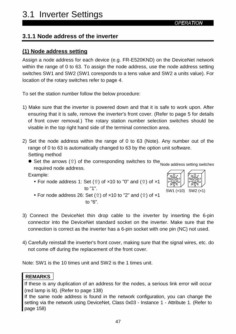
3.1 Inverter Settings
47
3 OPERATION/CONTROL3.1 Inverter Settings
3.1.1 Node address of the inverter
(1) Node address setting
Assign a node address for each device (e.g. FR-E520KND) on the DeviceNet networkwithin the range of 0 to 63. To assign the node address, use the node address settingswitches SW1 and SW2 (SW1 coresponds to a tens value and SW2 a units value). Forlocation of the rotary switches refer to page 4.
To set the station number follow the below procedure:
1) Make sure that the inverter is powered down and that it is safe to work upon. Afterensuring that it is safe, remove the inverter's front cover. (Refer to page 5 for detailsof front cover removal.) The rotary station number selection switches should bevisable in the top right hand side of the terminal connection area.
2) Set the node address within the range of 0 to 63 (Note). Any number out of therange of 0 to 63 is automatically changed to 63 by the option unit software.Setting method" Set the arrows (%) of the corresponding switches to the
required node address.Example:
! For node address 1: Set (%) of ×10 to "0" and (%) of ×1to "1".
! For node address 26: Set (%) of ×10 to "2" and (%) of ×1to "6".
SW1 (×10)
0987 654321 0987 654321
Node address setting switches
SW2 (×1)
3) Connect the DeviceNet thin drop cable to the inverter by inserting the 6-pinconnector into the DeviceNet standard socket on the inverter. Make sure that theconnection is correct as the inverter has a 6-pin socket with one pin (NC) not used.
4) Carefully reinstall the inverter's front cover, making sure that the signal wires, etc. donot come off during the replacement of the front cover.
Note: SW1 is the 10 times unit and SW2 is the 1 times unit.
REMARKS
If these is any duplication of an address for the nodes, a serious link error will occur(red lamp is lit). (Refer to page 138)If the same node address is found in the network configuration, you can change thesetting via the network using DeviceNet, Class 0x03 - Instance 1 - Attribute 1. (Refer topage 158)

48
(2) Changing Node Addresses
The state of the node address is sampled once at power on. Changing the addresslater on will have no effect and the software will keep the number read at power on.
The following procedure explains how to change the Node address switches:1) Turn power to the inverter off.2) Remove the inverter cover.3) Disconnect drop cable from inverter unit.4) Set the Node address (rotary switches) as desired.5) Reconnect the drop cable to the inverter unit.6) Reinstall inverter cover.7) Turn inverter power back on.
3

3.2 Configuration
49
3.2 Configuration
This section is intended to facilitate the configuration of the FR-E500KND inverter withminimum effort. The description assumes that each value is the factory setting value. Ifthe user wishes to change these values, the data necessary to do so is provided laterin the manual.
This section also assumes that the network cabling is complete and DeviceNetcommunication has been established. The LED status of the inverter must be blinkinggreen or steady green as described on page 25.
3.2.1 General description
The inverter is regarded as a slave device in the DeviceNet Communication Standard.This means that the inverter cannot start a message on the network. A master devicemust establish a connection to the inverter unit and then send commands, requests forinformation, etc. (Note)Note: When the master station is set-up and turned on, the inverter unit may need up
to 1 minute to get set to a ready for communication status.This is a situation may occur for just the DeviceNet configuration stage, so thisshould not be a general problem.
The FR-E500KND supports group 3 messaging as defined in the DeviceNet Standard.This feature means that one master can control the inverter while another master isable to read data from the same inverter. This also means that the DeviceNet mastermust support the UCMM protocol for proper operation.Note: It is strongly recommended that the user configures the DeviceNet network
using a software tool designed specifically for that purpose. The use of such atool greatly simplifies the configuration, reduces confusion, and enhancesaccuracy. Additionally, the configuration tool will facilitate the elimination ofconflicts between network devices and ensure consistency throughout thenetwork.
One such tool is DeviceNet Manager™ as supplied by Rockwell Automation. Tools areavailable from many other suppliers but the descriptions contained in the GettingStarted section are based upon the use of DeviceNet Manager™.
To use the DeviceNet Manager™ software, you will need to acquire the DeviceNetElectronic Data Sheet (EDS) file. The EDS file is a standard DeviceNet file whichdefines the configurable parameters of a field device and facilitates the networkconfiguration software’s ability to recognize a specific field device. Please refer to theconfiguration software tool instruction manual for more information about theinstallation and use of EDS files.
The most recent revision of the FR-E500KND EDS file is available on the Internet aswell as a separate item from Mitsubishi Electric.Refer to page 180 for details on how to get this file.

50
3.2.2 Set baud rate:
The baud rate must be consistent throughout the network in order to establishcommunication and allow configuration via the network.Therefore, this setting is important in the inverter unit configuration.
! Switching power on initializes the FR-E500KND to the communication speed of125Kbps.
! You can set the baudrate via the network using DeviceNet, Class 0x03 - Instance 1 -Attribute 2. (Refer to page 158)
! By changing the Pr. 346 and Pr. 348 values, you can set the baudrate manuallyfrom the parameter unit. (Refer to page 125)
3.2.3 Set node address:
The node address assigned to the inverter on page 47 establishes the default nodeaddress when the inverter is powered on. If the same node address is found in thenetwork configuration, you can change the setting via the network using DeviceNet,Class 0x03 - Instance 1 - Attribute 1. (Refer to page 158)
3.2.4 DeviceNet I/O assembly:
Communication between a master device and a slave device on the network requiresthat the DeviceNet Class 0x04 – "Assembly Object" in both devices be the same.
(1) Default I/O assembly:
When power is switched on, the FR-E500KND is set to Class 0x04 - Output Instance21 and Class 0x04 - Input Instance 71 as set at the factory. Refer to page 159 forfurther information on DeviceNet Class 0x04 and changing the desired Output andInput Instances.
(2) Polling rate:
Determination of the proper polling rate of the DeviceNet master device is dependentupon the characteristics of the entire network. To minimize a collision and maximizesystem reliability, we recommend that you set the polling rate intervals to be at least30ms. The user may, at their discretion, adjust this rate as network performanceallows.
3

51
(3) Loss of communications
In the default polled communication mode, the FR-E500KND will respond to loss ofcommunication based upon the configuration of the EPR bits of Pr. 345 and Pr. 347 asdefined on page 125. The default value of these bits is decimal 0. Such loss of pollingmay occur upon physical disconnection of network cabling, network power loss, failurewithin the master, etc.
When the EPR bits of Pr. 345 and Pr. 347 are set to decimal 0, the inverter willcontinue to execute the last command received until the communication time-out isreached. This time out value is equal to 4 times the Expected Packet Rate (Note thatthis EPR is as set by the DeviceNet master. This is different to the setting of the EPRbits of Pr. 345 and Pr. 347) as configured by the user. When the inverter times out, itwill generate an E.OPT error and coasts to a stop.
When the EPR bits of Pr. 345 and Pr. 347 are set to decimal 2, the inverter willcontinue to execute the last command received until another command is issued. TheFR-E520KND inverter will ignore the communication loss, generate no error andautomatically reset the connection when communication is restored.

3.3 Operation
52
3.3 Operation
The operation modes will be explained as follow. Also parameter definitions for specificDeviceNet parameters are described.
3.3.1 Operation modes
PU operation modeControl of the inverter is from the parameter unit (PU).
DeviceNet operation modeControl of the inverter is via commands from a DeviceNet master.
Operation mode selectionThe following conditions must be met before a mode change can be effected:! Inverter is stopped.! Forward and reverse commands are off.
3.3.2 Functions available in the operation modes
The functions of the inverter depend upon the operation mode. The following chartindicates the available commands according to the inverter operation mode.
Operation modeControl type Command type
DeviceNet PUOperation command Yes NoOutput frequency setting Yes NoMonitor Yes Yes
Parameter writeYes (Note 2)
(while stopped)No
(Note 2)Parameter read Yes Yes
DeviceNet
Inverter reset Yes (Note 1) NoOperation command No NoOutput frequency setting No No
Externalterminals
Inverter reset Yes Yes
Note: 1. The inverter cannot be reset if a communication error occurs.2. As set in Pr. 773. When the parameter unit (FR-PU04) is used, the external terminals are used
for control of the inverter. The inverter does not have terminals for directcontrol of operation commands or frequency setting.
3

53
3.3.3 Input from DeviceNet to inverter
Control input commandsThe FR-E500KND supports STF and STR. Some other Control Input Commands aresupported as well.
Output Frequency SettingOutput frequency setting is possible for the range 0 to 400 Hz in increments of 0.01 Hz.
Inverter resetThe inverter can be reset via DeviceNet using the ldentity Object reset service.Note that this reset service also performs a parameter clear, the type of which dependsupon the type of the ldentity Object reset service. (Refer to page 157.)
Parameter writingRefer to page 173 for parameters.
3.3.4 Output from inverter to DeviceNet
Inverter statusThe inverter status can be monitored using class 0x2A, attribute 114, the FR-E500KNDinverter status. This is a bitmapped status byte defined as follows:
Bit Definition0 Running (RUN)1 Forward running (FWD)2 Reverse running (REV)3 Up to frequency (SU)4 Overload (OL)5 — —6 Frequency detection (FU)7 Alarm —
Inverter monitoring! Output frequency! Output current! Output voltage
Parameter readRefer to page 173 for parameters.
Some inverter parameters require configuration to be viewed via the PU. All supportedparameters are fully accessible regardless of inverter configuration in such cases.

54
3.3.5 Operation on alarm occurrence
The following table shows the behavior of the inverter and network communicationoperation on alarm occurrence.
Operation modeType of fault Item
Net mode PU modeInverter operation Stop Stop
Inverter (Note 3) Networkcommunication
Continue Continue
Inverter operation Stop (Note 1) ContinueDeviceNet(Note 4)Communication
Networkcommunication
Continue(Note 2)
Continue(note 2)
Note: 1. Inverter operation stops on expiration of lnactivity/Watchdog timer ofConnection Object.
2. Depends on the type of communication fault.3. Examples, E.OPT, E.OC1.4. Examples, Status LED is Blinking Red LED, Red LED.
Please refer to Page 127 for more details.
3.3.6 Inverter reset
Inverter reset behavior is as explained on page 53.
3.3.7 Setting frequency (f) value
Frequency setting in RAM can be made using Class 0x2A - Instance 1 - Attributes 112,113. (Refer to Page 170)
3.3.8 Parameter clear (Pr Clr) commands
To execute the parameter clear commands, use Class 0x2A - Instance 1 - Attributes102 to 106.
3.3.9 Control input commands
To send any control input command, use Class 0x2A - Instance 1 - Attribute 114. Forexample, setting it with value 0x0002 will cause the inverter to run forward (FWD) atthe frequency value set in RAM.
Refer to the following bitmap tables for details:7 6 5 4 3 2 1 00 0 RL * RM * RH * STR STF 0
15 14 13 12 11 10 9 80 0 0 0 0 MRS * 0 0
* Input terminal function choices (Pr.180 to Pr.183) change terminal functions.
3

C H A P T E R 4
P A R A M E T E R S
This chapter explains the "parameters" of this product.
With the factory settings, the inverter is designed to perform
simple variable-speed operation. Set necessary parameter
values according to the load and operating specifications.
Always read the instructions before using the equipment.
4.1 Parameter List .......................................................... 55
4.2 Parameter Function Details ...................................... 62
Note: By making parameter setting, you can change the functions ofcontact input terminals MRS and contact output terminals A, B,C. Therefore, signal names corresponding to the functions areused in the description of this chapter (except in the wiringexamples). Note that they are not terminal names.
CHAPTER 4
PARAMETERS
Chapter 1
Chapter 2
Chapter 3
Chapter 4
Chapter 5
Chapter 6

4.1 Parameter ListPARAMETERS
55
4 PARAMETERS4.1 Parameter List
4.1.1 Parameter list
Func-tion
Param-eter
NumberName
SettingRange
MinimumSetting
Increments
FactorySetting
ReferTo:
Custo-mer
Setting0 Torque boost (Note 1) 0 to 30% 0.1% 6% 621 Maximum frequency 0 to 120Hz 0.01Hz 120Hz 632 Minimum frequency 0 to 120Hz 0.01Hz 0Hz 633 Base frequency (Note 1) 0 to 400Hz 0.01Hz 60Hz 64
4Multi-speed setting(high speed)
0 to 400Hz 0.01Hz 60Hz 65
5Multi-speed setting(middle speed)
0 to 400Hz 0.01Hz 30Hz 65
6Multi-speed setting(low speed)
0 to 400Hz 0.01Hz 10Hz 65
7 Acceleration time0 to 3600 s/0 to 360 s
0.1 s/0.01 s5 s/10s(Note 2)
66
8 Deceleration time0 to 3600 s/0 to 360 s
0.1 s/0.01 s5 s/10s(Note 2)
66
Basi
c fu
nct
ions
9 Electronic thermal O/L relay 0 to 500A 0.01A
Ratedoutputcurrent(Note 3)
68
10DC injection brakeoperation frequency
0 to 120Hz 0.01Hz 3Hz 69
11DC injection brakeoperation time
0 to 10 s 0.1 s 0.5 s 69
12 DC injection brake voltage 0 to 30% 0.1% 6% 6913 Starting frequency 0 to 60Hz 0.01Hz 0.5Hz 70
14Load pattern selection(Note 1)
0 to 3 1 0 71
18High-speed maximumfrequency
120 to400Hz
0.1Hz 120Hz 63
19Base frequency voltage(Note 1)
0 to 1000V,8888,9999
0.1V 9999 64
20Acceleration/decelerationreference frequency
1 to 400Hz 0.01Hz 60Hz 66
21Acceleration/decelerationtime increments
0, 1 1 0 66
22Stall prevention operationlevel
0 to 200% 0.1% 150% 72
23
Stall prevention operationlevel compensation factor atdouble speed(Note 4)
0 to 200%,9999
0.1% 9999 72
24Multi-speed setting(speed 4)
0 to 400Hz,9999
0.01Hz 9999 65
25Multi-speed setting(speed 5)
0 to 400Hz,9999
0.01Hz 9999 65
26Multi-speed setting(speed 6)
0 to 400Hz,9999
0.01Hz 9999 65
27Multi-speed setting(speed 7)
0 to 400Hz,9999
0.01Hz 9999 65
29Acceleration/decelerationpattern
0, 1, 2 1 0 74
Sta
ndard
opera
tion f
unct
ions
30Regenerative functionselection
0, 1 1 0 75
Par
amet
er L
ist

PARAMETERS
56
Func-tion
Param-eter
NumberName
SettingRange
MinimumSetting
Increments
FactorySetting
ReferTo:
Custo-mer
Setting
31 Frequency jump 1A0 to 400Hz,
99990.01Hz 9999 76
32 Frequency jump 1B0 to 400Hz,
99990.01Hz 9999 76
33 Frequency jump 2A0 to 400Hz,
99990.01Hz 9999 76
34 Frequency jump 2B0 to 400Hz,
99990.01Hz 9999 76
35 Frequency jump 3A0 to 400Hz,
99990.01Hz 9999 76
36 Frequency jump 3B0 to 400Hz,
99990.01Hz 9999 76
Sta
ndard
opera
tion f
unct
ions
37 Speed display0,
0.01 to 99980.001 r/min 0 77
41 Up-to-frequency sensitivity 0 to 100% 0.1% 10% 7842 Output frequency detection 0 to 400Hz 0.01Hz 6Hz 78
Outp
ut
term
inal
funct
ions
43Output frequency detectionfor reverse rotation
0 to 400Hz,9999
0.01Hz 9999 78
44Second acceleration/deceleration time
0 to 3600 s/0 to 360 s
0.1 s/0.01 s 5s 66
45 Second deceleration time0 to 3600 s/0 to 360 s,
99990.1 s/0.01 s 9999 66
46Second torque boost(Note 1)
0 to 30%,9999
0.1% 9999 62
47Second V/F (basefrequency) (Note 1)
0 to 400Hz,9999
0.01Hz 9999 64Seco
nd f
unct
ions
48Second electronicovercurrent protection
0 to 500A,9999
0.01A 9999 68
Dis
pla
yfu
nct
ions
52PU main display dataselection
0, 23, 100 1 0 79
57 Restart coasting time0 to 5 s,
99990.1 s 9999 81
Aut
omat
icre
star
tfu
nctio
ns
58 Restart cushion time 0 to 60 s 0.1 s 1.0 s 81
60 Shortest acceleration/deceleration mode
0, 1, 2, 11,12 1 0 82
61 Reference I for intelligentmode
0 to 500A,9999 0.01A 9999 82
62 ref. I for intelligent modeaccel
0 to 200%,9999 1% 9999 82
63 ref. I for intelligent modedecel
0 to 200%,9999 1% 9999 82
65 Retry selection 0, 1, 2, 3 1 0 84
66Stall prevention operationlevel reduction startingfrequency (Note 4)
0 to 400Hz 0.01Hz 60Hz 72
67 Number of retries at alarmoccurrence
0 to 10,101 to 110 1 0 84
68 Retry waiting time 0.1 to 360 s 0.1 s 1 s 8469 Retry count display erasure 0 1 0 84
Opera
tion s
ele
ctio
n f
unct
ions
70 Special regenerative brakeduty 0 to 30% 0.1% 0% 75
Par
amet
er L
ist
4

PARAMETERS
57
Func-tion
Param-eter
NumberName
SettingRange
MinimumSetting
Increments
FactorySetting
ReferTo:
Custo-mer
Setting
71 Applied motor (Note 4)
0, 1, 3, 5, 6,13, 15, 16,
23, 100, 101,103, 105,106, 113,115, 116,
123,
1 0 86
72 PWM frequency selection 0 to 15 1 1 87
75Reset selection/disconnected PU detection/PU stop selection
0 to 3,14 to 17 1 14 88
77 Parameter write disableselection 0, 2 1 0 90
78 Reverse rotation preventionselection 0, 1, 2 1 0 90O
pera
tion s
ele
ctio
n f
unct
ions
79 Operation mode selection(Note 4) 0, 1, 2 1 2 91
80 Motor capacity (Note 4)0.1 to
7.5kW, 99990.01kW 9999 92
82 Motor exciting current0 to 500A,
99990.01A 9999 93
83Rated motor voltage(Note 4)
0 to 1000V 0.1V 200V 93
84Rated motor frequency(Note 4)
50 to 120Hz 0.01Hz 60Hz 93
90 Motor constant (R1)0 to 50Ω,
99990.001Ω 9999 93M
oto
r co
nst
ants
96Auto-tuning setting/status(Note 4)
0, 1 1 0 93
117 Station number 0 to 31 1 0 99118 Communication speed 48, 96, 192 1 192 99
119 Stop bit length
0, 1(data length 8)
10, 11(data length 7)
1 1 99
120Parity checkpresence/absence
0, 1, 2 1 2 99
121Number of communicationretries
0 to 10,9999 1 1 99
122Communication check timeinterval
0, 0.1 to999.8 s,
99990.1 s 0 99
123 Waiting time setting0 to 150,
99991 9999 99
Com
munic
atio
n f
unct
ions
124CR • LF presence/absenceselection
0, 1, 2 1 1 99
Dis
pla
y
145Parameter unit displaylanguage selection
0 to 7 1 0 112
150Output current detectionlevel
0 to 200% 0.1% 150% 113
151Output current detectionperiod
0 to 10 s 0.1 s 0 113
152 Zero current detection level 0 to 200.0% 0.1% 5.0% 114
Curr
ent dete
ctio
n
153Zero current detectionperiod
0.05 to 1 s 0.01 s 0.5 s 114
Par
amet
er L
ist

PARAMETERS
58
Func-tion
Param-eter
NumberName
SettingRange
MinimumSetting
Increments
FactorySetting
ReferTo:
Custo-mer
Setting
Sub
funct
ion
156Stall prevention operationselection
0 to 31,100 1 0 115
160 User group read selection 0, 1, 10, 11 1 0 117
168
Additi
onal
funct
ion
169Parameters set by manufacturer. Do not set.
Initi
al
monito
r
171Actual operation hour meterclear
0 0 118
173 User group 1 registration 0 to 999 1 0 117
174 User group 1 deletion0 to 999,
99991 0 117
175 User group 2 registration 0 to 999 1 0 117
Use
r fu
nct
ions
176 User group 2 deletion0 to 999,
99991 0 117
180(RL) function selection(Note 4)
0 to 18 1 0 118
181(RM) function selection(Note 4)
0 to 18 1 1 118
182(RH) function selection(Note 4)
0 to 18 1 2 118
183MRS terminal (MRS)function selection (Note 4)
0 to 18 1 6 118
190(RUN) function selection(Note 4)
0 to 99 1 0 120
191(FU) function selection(Note 4)
0 to 99 1 4 120Term
inal (
Devi
ceN
et I
/O)
ass
ignm
ent fu
nct
ions
192A, B, C terminal (ABC)function selection (Note 4)
0 to 99 1 99 120
232Multi-speed setting(speed 8)
0 to 400Hz,9999
0.01Hz 9999 65
233Multi-speed setting(speed 9)
0 to 400Hz,9999
0.01Hz 9999 65
234Multi-speed setting(speed 10)
0 to 400Hz,9999
0.01Hz 9999 65
235Multi-speed setting(speed 11)
0 to 400Hz,9999
0.01Hz 9999 65
236Multi-speed setting(speed 12)
0 to 400Hz,9999
0.01Hz 9999 65
237Multi-speed setting(speed 13)
0 to 400Hz,9999
0.01Hz 9999 65
238Multi-speed setting(speed 14)
0 to 400Hz,9999
0.01Hz 9999 65
Multi
-speed o
pera
tion
239Multi-speed setting(speed 15)
0 to 400Hz,9999
0.01Hz 9999 65
4
Par
amet
er L
ist

PARAMETERS
59
Func-tion
Param-eter
NumberName
SettingRange
MinimumSetting
Increments
FactorySetting
ReferTo:
Custo-mer
Setting240 Soft-PWM setting 0, 1 1 1 87
244Cooling fan operationselection
0, 1 1 0 121
245 Rated motor slip0 to 50%,
99990.01% 9999 122
246Slip compensationresponse time
0.01 to 10 s 0.01 s 0.5 s 122
247Constant-output region slipcompensation selection
0, 9999 1 9999 122Sub f
unct
ions
249Ground fault detection atstart
0, 1 1 0 123
Sto
pse
lect
ion
funct
ion
250 Stop selection
0 to 100 s,1000 to1100 s,
8888, 9999
1 9999 123
345DeviceNet address startupdata (Lower byte)
0 to 255 1 63 (0x3F) 125
346DeviceNet baudrate startupdata (Lower byte)
0 to 255 1 132 (0x84) 125
347DeviceNet address startupdata (Higher byte)
0 to 255 1 160 (0xA0) 125
Devi
ceN
et
funct
ions
348DeviceNet baudrate startupdata (Higher byte)
0 to 255 1 80 (0x50) 125
990 Buzzer beep control 0, 1 1 1 112
Dis
pla
y
991 LCD contrast 0 to 63 1 53 112
Note:1. Indicates the parameter of which setting is ignored when the general-purpose magnetic flux vector control mode is selected.
2. The setting depends on the inverter capacity: (0.1K to 3.7K)/(5.5K to 7.5K).3. Set to 85% of the rated inverter current for the 0.1K to 0.75K.4. If "2" is set in Pr. 77 (parameter write inhibit selection), the setting cannot be
changed during operation.5. The half-tone screened parameters allow their settings to be changed during
operation if "0" (factory setting) has been set in Pr. 77 (parameter writeinhibit selection). (However, the Pr. 72 and Pr. 240 value may be changedduring PU operation only.)
Par
amet
er L
ist

PARAMETERS
60
4.1.2 List of parameters classified by purpose of use
Set the parameters according to the operating conditions. The following list indicatespurpose of use and corresponding parameters.
Parameter NumbersPurpose of Use
Parameter numbers which must be set
Operation mode selection Pr. 79Acceleration/decelerationtime/pattern adjustment
Pr. 7, Pr. 8, Pr. 20, Pr. 21, Pr. 29
Selection of output characteristicsoptimum for load characteristics
Pr. 3, Pr. 14, Pr. 19
Output frequency restriction (limit) Pr. 1, Pr. 2, Pr. 18Operation over 60Hz Pr. 1, Pr. 18Motor output torque adjustment Pr. 0, Pr. 80Brake operation adjustment Pr. 10, Pr. 11, Pr. 12
Multi-speed operationPr. 1, Pr. 2, Pr. 4, Pr. 5, Pr. 6, Pr. 24, Pr. 25,Pr. 26, Pr. 27, Pr. 232, Pr. 233, Pr. 234,Pr. 235, Pr. 236, Pr. 237, Pr. 238, Pr. 239
Frequency jump operation Pr. 31, Pr. 32, Pr. 33, Pr. 34, Pr. 35, Pr. 36Automatic restart operation afterinstantaneous power failure
Pr. 57, Pr. 58
Optimum acceleration/decelerationwithin continuous rated range
Pr. 60
Slip compensation setting Pr. 245 to Pr. 247Output stop method selection Pr. 250
Rel
ated
to
oper
atio
n
Setting of output characteristicsmatching the motor
Pr. 3, Pr. 19, Pr. 71
General-purpose magnetic flux vectorcontrol operation
Pr. 80
Electromagnetic brake operationtiming
Pr. 42, Pr. 190 to Pr. 192
Offline auto tuning setting Pr. 82 to Pr. 84, Pr. 90, Pr. 96
Sub-motor operationPr. 0, Pr. 3, Pr. 7, Pr. 8, Pr. 9, Pr. 44, Pr. 45,Pr. 46, Pr. 47, Pr. 48
Regenerative function selection Pr. 30, Pr. 70Operation in communication withpersonal computer
Pr. 117 to Pr. 124Rel
ated
to
appl
icat
ion
oper
atio
n
Noise reduction Pr. 72, Pr. 240
4

PARAMETERS
61
Parameter NumbersPurpose of Use
Parameter numbers which must be set
Display of speed, etc. Pr. 37, Pr. 52
Rel
ated
to
mon
itorin
g
Clearing of inverter's actual operationtime
Pr. 171
Function write prevention Pr. 77
Reverse rotation prevention Pr. 78
Parameter grouping Pr. 160, Pr. 173 to Pr. 176
Current detection Pr. 150 to Pr. 153, Pr. 190 to Pr. 192
Rela
ted t
o in
corr
ect
opera
tion p
reve
ntio
n
Motor stall prevention Pr. 22, Pr. 23, Pr. 66, Pr. 156
Input terminal (DeviceNet input)function assignment
Pr. 180 to Pr. 183
Output terminal (DeviceNet output)function assignment
Pr. 190 to Pr. 192
Increased cooling fan life Pr. 244Motor protection from overheat Pr. 9, Pr. 71Automatic restart operation at alarmstop
Pr. 65, Pr. 67, Pr. 68, Pr. 69
Setting of ground fault overcurrentprotection
Pr. 249
Oth
ers
Inverter reset selection Pr. 75
4.1.3 Parameters recommended to be set by the user
We recommend the following parameters to be set by the user.Set them according to the operation specifications, load, etc.
ParameterNumber
Name Application
1 Maximum frequency2 Minimum frequency
Used to set the maximum and minimum outputfrequencies.
7 Acceleration time8 Deceleration time
Used to set the acceleration and decelerationtimes.
9Electronic thermal O/Lrelay
Used to set the current of the electronicovercurrent protection to protect the motor fromoverheat.
14 Load pattern selectionUsed to select the optimum output characteristicswhich match the application and loadcharacteristics.
71 Applied motorUsed to set the thermal characteristics of theelectronic overcurrent protection according to themotor used.

PARAMETERS
62
4.2 Parameter Function Details
Pr. 3 "base frequency"Pr. 19 "base frequency voltage"Pr. 71 "applied motor"Pr. 80 "motor capacity"Pr. 180 to Pr. 183 (input terminal
(DeviceNet input) function selection)
Related parameters
4.2 Parameter Function Details
4.2.1 Torque boost (Pr. 0, Pr. 46)
Pr. 0 "torque boost"
Pr. 46 "second torque boost"
Increase the setting when the inverter-to-motor distance is long or motor torque in thelow-speed range is insufficient, for example;" Motor torque in the low-frequency range can be adjusted to the load to increase the
starting motor torque." You can select either of the two starting torque boosts by RT terminal switching.
ParameterNumber
FactorySetting
Setting Range Remarks
0 6% 0 to 30% 46 9999 0 to 30%, 9999 9999: Function invalid
Pr.0Pr.46 Setting range
0
100%
Outp
ut vo
ltage
Output frequency (Hz)
Base frequency
<Setting>
! Assuming that the base frequency voltage is 100%, set the 0Hz voltage in %.! Pr. 46 "Second torque boost" is valid when the RT signal is on. (Note 3)! When using the inverter-dedicated motor (constant-torque motor), change the
setting as indicated below:FR-E520-0.1KND to 0.75KND ............................................................................... 6%FR-E520-1.5KND to 7.5KND ................................................................................. 4%If you leave the factory setting as it is and change the Pr. 71 value to the setting foruse of the constant-torque motor, the Pr. 0 setting changes to the above value.
Note:1. This parameter setting is ignored when the general-purpose magnetic fluxvector control mode has been selected.
2. A large setting may result in an overheated motor or overcurrent trip. Theguideline for the largest value for this parameter is about 10%.
3. The RT signal serves as the second function selection signal and makes theother second functions valid. Refer to page 118 for Pr. 180 to Pr. 183 (inputterminal (DeviceNet input) function selection).
4. When terminal (DeviceNet input) assignment is changed using Pr. 180 toPr. 183 during use of the second functions, the other functions may beaffected. Check the functions of the corresponding terminals (DeviceNetinput) before making setting.
4

PARAMETERS
63
Pr. 13 "starting frequency"Pr. 79 "operation mode selection"
Related parameters
4.2.2 Output frequency range (Pr. 1, Pr. 2, Pr. 18)
Pr. 1 "maximum frequency"
Pr. 2 "minimum frequency"
Pr. 18 "high-speed maximum frequency"
Used to clamp the upper and lower limits of theoutput frequency. Used for high-speed operation ator over 120Hz." Can be used to set the upper and lower limits of motor speed.
ParameterNumber
FactorySetting
SettingRange
1 120Hz 0 to 120Hz2 0Hz 0 to 120Hz
18 120Hz120 to400Hz
Output frequency (Hz)
Pr.1Pr.18
Pr.2 Frequency setting
5,10V(20mA)
0(4mA)
" Output frequency range (Pr. 1, Pr. 2, Pr. 18
<Setting>
! Use Pr. 1 to set the upper limit of the output frequency. If the frequency of thefrequency command entered is higher than the setting, the output frequency isclamped at the maximum frequency.
! To perform operation over 120Hz, set the upper limit of the output frequency inPr. 18.(When the Pr. 18 value is set, Pr. 1 automatically changes to the frequency inPr. 18. Also, when the Pr. 1 value is set, Pr. 18 automatically changes to thefrequency in Pr. 1.)
! Use Pr. 2 to set the lower limit of the output frequency.
CAUTION
When the Pr. 2 setting is higher than the Pr. 13 "starting frequency" value,note that the motor will run at the set frequency by merely switching thestart signal on, without entering the command frequency.

PARAMETERS
64
Pr. 14 "load pattern selection"Pr. 71 "applied motor"Pr. 80 "motor capacity"Pr. 83 "rated motor voltage"Pr. 180 to Pr. 183 (input terminal
(DeviceNet input) function selection)
Related parameters
" " Base frequency, base frequency voltage (Pr. 3, Pr. 19, Pr. 47)4.2.3 Base frequency, base frequency voltage (Pr. 3, Pr. 19, Pr. 47)
Pr. 3 "base frequency"
Pr. 19 "base frequency voltage"
Pr. 47 "second V/F (base frequency)
Used to adjust the inverter outputs (voltage, frequency) to the motor rating." When running a standard motor, generally set the rated motor frequency. When
running the motor using the commercial power supply-inverter switch-over, set thebase frequency to the same value as the power supply frequency.
" If the frequency given on the motor rating plate is "50Hz" only, always set to "50Hz".Leaving it as "60Hz" may make the voltage too low and the torque less, resulting inoverload tripping. Care must be taken especially when Pr. 14 "load pattern selection"= 1.
ParameterNumber
FactorySetting
SettingRange Remarks
3 60Hz 0 to 400Hz
19 9999 0 to 1000V,8888, 9999
8888: 95% of power supply voltage9999: Same as power supply voltage
47 9999 0 to 400Hz,9999
9999: Function invalid
Pr.19
Outp
ut vo
ltage
Pr.3 Pr.47
Outputfrequency (Hz)
<Setting>
! Use Pr. 3 and Pr. 47 to set the base frequency (rated motor frequency). Two basefrequencies can be set and the required frequency can be selected from them.
! Pr. 47 "Second V/F (base frequency)" is valid when the RT signal is on. (Note 3)! Use Pr. 19 to set the base voltage (e.g. rated motor voltage).
Note:1. Set 60Hz in Pr. 3 "base frequency" when using a Mitsubishi constant-torquemotor.
2. When the general-purpose magnetic flux vector control mode has beenselected, Pr. 3, Pr. 19 and Pr. 47 are made invalid and Pr. 83 and Pr. 84 aremade valid.However, Pr. 3 or Pr. 47 is made valid for the S-shaped inflection patternpoint of Pr. 29.
3. The RT signal serves as the second function selection signal and makes theother second functions valid. Refer to page 118 for Pr. 180 to Pr. 183 (inputterminal (DeviceNet input) function selection).
4

PARAMETERS
65
" " Multi-speed operation (Pr. 4 to Pr. 6, Pr. 24 to Pr. 27, Pr. 232 to Pr. 239)4.2.4 Multi-speed operation (Pr. 4, Pr. 5, Pr. 6, Pr. 24 to Pr. 27, Pr. 232 to Pr. 239)
Pr. 4 "multi-speed setting (high speed)"
Pr. 5 "multi-speed setting (middle speed)"
Pr. 6 "multi-speed setting (low speed)"
Pr. 24 to Pr. 27 "multi-speed setting(speeds 4 to 7)"
Pr. 232 to Pr. 239 "multi-speed setting(speeds 8 to 15)"
Used to switch between the predetermined runningspeeds." Each speed can be selected just by turning the
RH, RM, RL and REX signals (DeviceNet input) ON and OFF." By using these functions with Pr. 1 "maximum
frequency" and Pr. 2 "minimum frequency", up to 17 speeds can be set." Valid in the DeviceNet™ operation mode.
Parameter Number Factory Setting Setting Range Remarks4 60Hz 0 to 400Hz5 30Hz 0 to 400Hz6 10Hz 0 to 400Hz
24 to 27 9999 0 to 400Hz, 9999 9999: Not selected232 to 239 9999 0 to 400Hz, 9999 9999: Not selected
Time(example)
RH
RM
RL
Speed 1(high speed)
Speed 2(middle speed)
Speed 5
Speed 6
Speed 7
ON
ON
ON
ON ON
ONON
ON
ON
ON
ON
Out
put f
req
uen
cy(H
z)
Speed 4Speed 3(low speed)
Pr. 182
Pr. 181
Pr. 180
Out
put
fre
que
ncy(
Hz)
Speed 9
Speed 10
Speed 11Speed 12
Speed 13
Speed 14
Speed 15
Time(example)
RH
RM
RL
REXON ON ON ON ON ON ON
ON ON ON ON
ON ON ON ON
ON ON ON ON
ON
Speed 8
Pr. 182
Pr. 181
Pr. 180
Pr. 183
<Setting>! Set the running frequencies in the corresponding parameters.! Each speed (frequency) can be set as desired between 0 and 400Hz during inverter operation.
When the parameter unit (FR-PU04) is used, the setting of the required multi-speedsetting parameter that has been read can be changed by pressing the / key. Inthis case, when you release the / key, press the WRITE key to store the setfrequency.
Pr. 1 "maximum frequency"Pr. 2 "minimum frequency"Pr. 29 "acceleration/deceleration
pattern"Pr. 79 "operation mode
selection"Pr. 180 to Pr. 183 (input terminal
(DeviceNet input) function selection)
Related parameters

PARAMETERS
66
Note:1. The multi-speeds can also be set in the PU or DeviceNet operation mode.2. For 3-speed setting, if two or three speeds are simultaneously selected,
priority is given to the frequency setting of the lower signal.3. Pr. 24 to Pr. 27 and Pr. 232 to Pr. 239 settings have no priority between
them.4. The parameter values can be changed during operation.5. When input terminal (DeviceNet input) assignment is changed using Pr. 180
to Pr. 183, the other functions may be affected. Check the functions of thecorresponding terminals (DeviceNet input) before making setting.
4.2.5 Acceleration/deceleration time (Pr. 7, Pr. 8, Pr. 20, Pr. 21,Pr. 44, Pr. 45)
" Acceleration/deceleration time (Pr. 7, Pr. 8, Pr. 20, Pr. 21, Pr. 44, Pr. 45)
Pr. 7 "acceleration time"
Pr. 8 "deceleration time"
Pr. 20 "acceleration/deceleration reference frequency"
Pr. 21 "acceleration/deceleration time increments"
Pr. 44 "second acceleration/deceleration time"
Pr. 45 "second deceleration time"Used to set motor acceleration/deceleration time.Set a larger value for a slower speed increase/decrease or a smaller value for a fasterspeed increase/decrease.
ParameterNumber Factory Setting Setting Range Remarks
0.1K to 3.7K 5s7 5.5K, 7.5K 10s 0 to 3600s/0 to 360s
0.1K to 3.7K 5s8 5.5K, 7.5K 10s 0 to 3600s/0 to 360s
20 60Hz 1 to 400Hz
21 0 0, 1 0: 0 to 3600s1: 0 to 360s
44 5s 0 to 3600s/0 to 360s
45 9999 0 to 3600s/0 to 360s, 9999
9999: acceleration time =deceleration time
Time
Pr.20
Pr.7Pr.44
Pr.8Pr.45
Running frequency
Acceleration Deceleration
Outp
ut fr
equency
(H
z)
Pr. 3 "base frequency"Pr. 29 "acceleration/deceleration
pattern"
Related parameters
4

PARAMETERS
67
<Setting> ! Use Pr. 21 to set the acceleration/deceleration time and minimum setting
increments:Set value "0" (factory setting)....0 to 3600s (minimum setting increments: 0.1s)Set value "1".............................. 0 to 360s (minimum setting increments: 0.01s)
! Use Pr. 7 and Pr. 44 to set the acceleration time required to reach the frequency setin Pr. 20 from 0Hz.
! Use Pr. 8 and Pr. 45 to set the deceleration time required to reach 0Hz from thefrequency set in Pr. 20.
! Pr. 44 and Pr. 45 are valid when the RT signal is on. ! Set "9999" in Pr. 45 to make the deceleration time equal to the acceleration time
(Pr. 44).
Note:1. In S-shaped acceleration/deceleration pattern A (refer to page 74), the settime is the period required to reach the base frequency set in Pr. 3.• Acceleration/deceleration time calculation expression when the set
frequency is the base frequency or higher
t = 49 ×
T(Pr. 3)2 × f 2 +
59 T
T: Acceleration/deceleration time setting (s)f : Set frequency (Hz)
• Guideline for acceleration/deceleration time at the base frequency of 60Hz(0Hz to set frequency)
2. When the setting of Pr. 7, Pr. 8, Pr. 44 or Pr. 45 is "0", the acceleration/deceleration time is 0.04 seconds. At this time, set 120Hz or less in Pr. 20.
3. When the RT signal is on, the other second functions such as second torqueboost are also selected.
4. If the shortest acceleration/deceleration time is set, the actual motoracceleration/deceleration time cannot be made shorter than the shortestacceleration/deceleration time determined by the mechanical system's J(inertia moment) and motor torque.
Frequency setting (Hz)Acceleration/deceleration time (s)
60 120 200 400
5 5 12 27 10215 15 35 82 305

PARAMETERS
68
" Electronic overcurrent protection (Pr. 9, Pr. 48)4.2.6 Electronic overcurrent protection (Pr. 9, Pr. 48)
Pr. 9 "electronic thermal O/L relay"
Pr. 48 "second electronic overcurrentprotection"
Set the current of the electronic overcurrent protection to protect the motor fromoverheat. This feature provides the optimum protective characteristics, includingreduced motor cooling capability, at low speed.
ParameterNumber
Factory Setting Setting Range Remarks
9Rated output
current*0 to 500A
48 9999 0 to 500A, 9999 9999: Function invalid
*0.1K and 0.75K are set to 85% of the rated inverter current.
<Setting>! Set the rated current [A] of the motor.
(Normally set the rated current at 50Hz if the motor has both 50Hz and 60Hz ratedcurrent.)
! Setting "0" makes the electronic overcurrent protection (motor protective function)invalid. (The inverter's protective function is valid.)
! When using a Mitsubishi constant-torque motor, first set "1" in Pr. 71 to choose the100% continuous torque characteristic in the low-speed range. Then, set the ratedmotor current in Pr. 9.
! Pr. 48 "Second electronic overcurrent protection" is made valid when the RT signalis on. (Note 4)
Note:1. When two or more motors are connected to the inverter, they cannot beprotected by the electronic overcurrent protection. Install an external thermalrelay to each motor.
2. When the difference between the inverter and motor capacities is large andthe setting is small, the protective characteristics of the electronicovercurrent protection will be deteriorated. In this case, use an externalthermal relay.
3. A special motor cannot be protected by the electronic overcurrent protection.Use an external thermal relay.
4. The RT signal serves as the second function selection signal and makes theother second functions valid. Refer to page 118 for Pr. 180 to Pr. 183 (input(DeviceNet input) terminal function selection).
Pr. 71 "applied motor"Pr. 180 to Pr. 183
(input terminal (DeviceNet input) function selection)
Related parameter
4

PARAMETERS
69
" " DC dynamic brake (Pr. 10, Pr. 11, Pr. 12)4.2.7 DC injection brake (Pr. 10 to Pr. 12)
Pr. 10 "DC injection brake operation frequency"
Pr. 11 "DC injection brake operation time"
Pr. 12 "DC injection brake voltage"
By setting the DC injection brake voltage (torque),operation time and operation starting frequency, the stopping accuracy of positioningoperation, etc. or the timing of operating the DC injection brake to stop the motor canbe adjusted according to the load.
ParameterNumber
FactorySetting
SettingRange
10 3Hz 0 to 120Hz11 0.5 s 0 to 10 s12 6% 0 to 30%
Operationfrequency
DC injectionbrake voltage
Outp
ut
frequen
cy (
Hz)
Time
Time
Pr.12
Operation timePr.11
Pr.10
Operationvoltage
<Setting>
! Use Pr. 10 to set the frequency at which the DC injection brake operation is started.! Use Pr. 11 to set the period during when the brake is operated.! Use Pr. 12 to set the percentage of the power supply voltage.! The setting value for Pr. 12 when using the inverter-dedicated motor (constant-
torque motor).FR-E520-0.1KND to 7.5KND ............................................................ 4% (Note)
Note: When the Pr. 12 value is as factory-set, changing the Pr. 71 value to thesetting for use of a constant-torque motor changes the Pr. 12 value to 4%automatically.
CAUTION
Install a mechanical brake. No holding torque is provided.
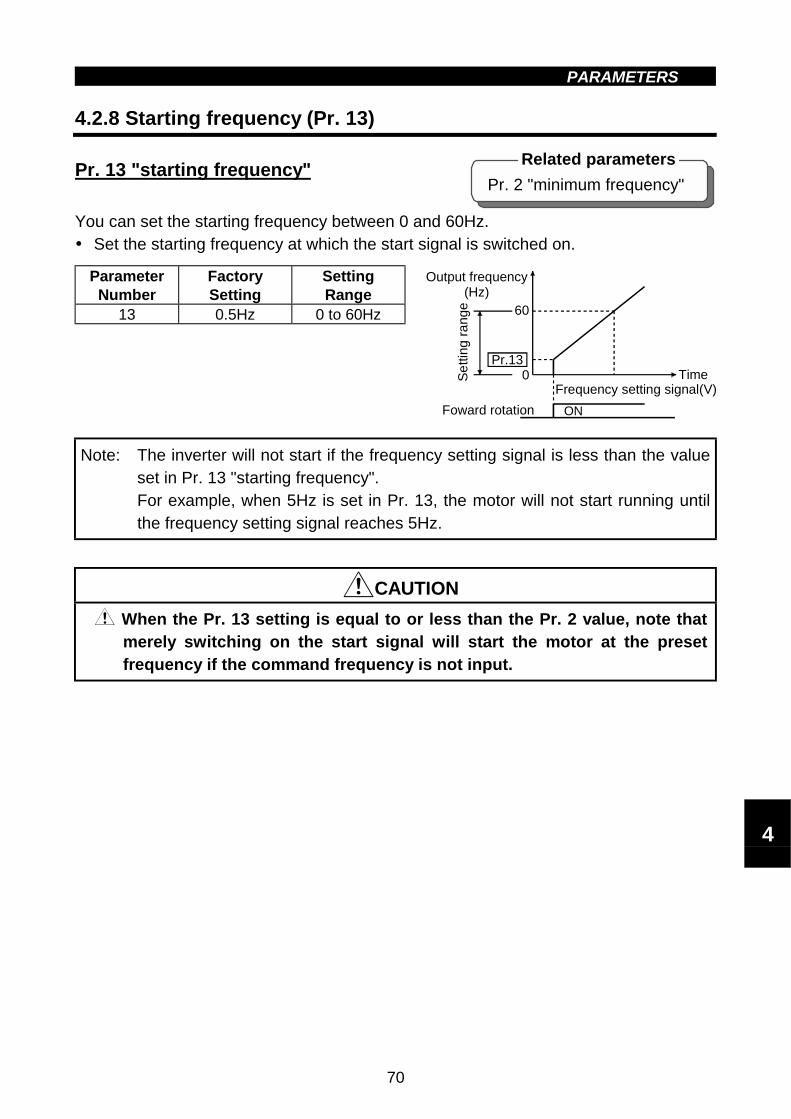
PARAMETERS
70
" Starting frequency (Pr. 13)4.2.8 Starting frequency (Pr. 13)
Pr. 13 "starting frequency"
You can set the starting frequency between 0 and 60Hz.! Set the starting frequency at which the start signal is switched on.
ParameterNumber
FactorySetting
SettingRange
13 0.5Hz 0 to 60Hz
Note: The inverter will not start if the frequency setting signal is less than the valueset in Pr. 13 "starting frequency".For example, when 5Hz is set in Pr. 13, the motor will not start running untilthe frequency setting signal reaches 5Hz.
CAUTION
When the Pr. 13 setting is equal to or less than the Pr. 2 value, note thatmerely switching on the start signal will start the motor at the presetfrequency if the command frequency is not input.
Time
60
Pr.13
ON
0
Output frequency(Hz)
Foward rotation
Frequency setting signal(V)
Se
tting
ra
nge
Pr. 2 "minimum frequency"
Related parameters
4

PARAMETERS
71
4.2.9 Load pattern selection (Pr. 14)" Load pattern selection (Pr. 14)
Pr. 14 "load pattern selection"
You can select the optimum output characteristic (V/F characteristic) for the applicationand load characteristics.
ParameterNumber
FactorySetting
SettingRange
14 0 0 to 3
100%
Pr.14=0For constant-torque loads(e.g. conveyor, cart)
Output voltage
Base frequencyOutput frequency (Hz)
Pr.14=1
100%Output voltage
Base frequencyOutput frequency (Hz)
For variable-torque loads(Fan, pump)
Pr.0Pr.46
Pr.14=2
100%Output voltage
Base frequencyOutput frequency (Hz)
For liftBoost for forward rotation...Pr. 0 (Pr.46) settingBoost for reverse rotation...0%
Forwardrotation
Reverserotation
Pr.0Pr.46
Pr.14=3
100%Output voltage
Base frequencyOutput frequency (Hz)
For liftBoost for forward rotation...0%Boost for reverse rotation...Pr. 0 (Pr.46) setting
Reverserotation
Forwardrotation
Note:1. This parameter setting is ignored when the general-purpose magnetic fluxvector control mode has been selected.
2. Pr. 46 "second torque boost" is made valid when the RT signal turns on.The RT signal acts as the second function selection signal and makes theother second functions valid.Refer to page 118 for Pr. 180 to Pr. 183 (input terminal (DeviceNet input)function selection).
Pr. 18 &&&&Refer to Pr. 1, Pr. 2.
Pr. 19 &&&&Refer to Pr. 3.
Pr. 20, Pr. 21 &&&&Refer to Pr. 7, Pr. 8.
Pr. 0 "torque boost"Pr. 46 "second torque boost"Pr. 80 "motor capacity"Pr. 180 to Pr. 183
(input terminal (DeviceNet input)function selection)
Related parameters

PARAMETERS
72
" " Stall prevention (Pr. 22, Pr. 23, Pr. 66)4.2.10 Stall prevention (Pr. 22, Pr. 23, Pr. 66)
Pr. 22 "stall prevention operation level"
Pr. 23 "stall prevention operation level compensation factor at double speed"
Pr. 66 "stall prevention operation level reduction starting frequency"
! Set the output current level at which the output frequency will be adjusted to preventthe inverter from stopping due to overcurrent etc.
! For high-speed operation at or over the motor base frequency, acceleration may notbe made because the motor current does not increase.To improve the operation characteristics of the motor in such a case, the stallprevention level in the high-frequency range can be reduced. This is effective foroperation of a centrifugal separator up to the high-speed range. Normally, set 60Hzin Pr. 66 and 100% in Pr. 23.
! For operation in the high-frequency range, the current in the locked motor state issmaller than the rated output current of the inverter and the inverter does not resultin an alarm (protective function is not activated) if the motor is at a stop. To improvethis and activate the alarm, the stall prevention level can be reduced.
ParameterNumber
FactorySetting
SettingRange
Remarks
22 150% 0 to 200%
23 99990 to 200%,
99999999: Constantaccording to Pr. 22
66 60Hz 0 to 400Hz
Pr.22
Pr.23
Pr.23 =9999
400HzPr.66
Red
uctio
n ra
tio
com
pens
atio
n fa
ctor
(%
)
Sta
ll pre
ventio
n
opera
tion le
vel (
%)
Output frequency (Hz)
150
90
604530
22.5
600 100 200 300 400
Setting example(Pr.22=150%, Pr.23=100%, Pr.66=60Hz)
Cu
rren
t lim
it o
pera
tion le
vel (
%)
Output frequency (Hz)
Pr. 9 "electronic thermal O/Lrelay"
Pr. 48 "second electronic overcurrent protection"
Related parameters
4
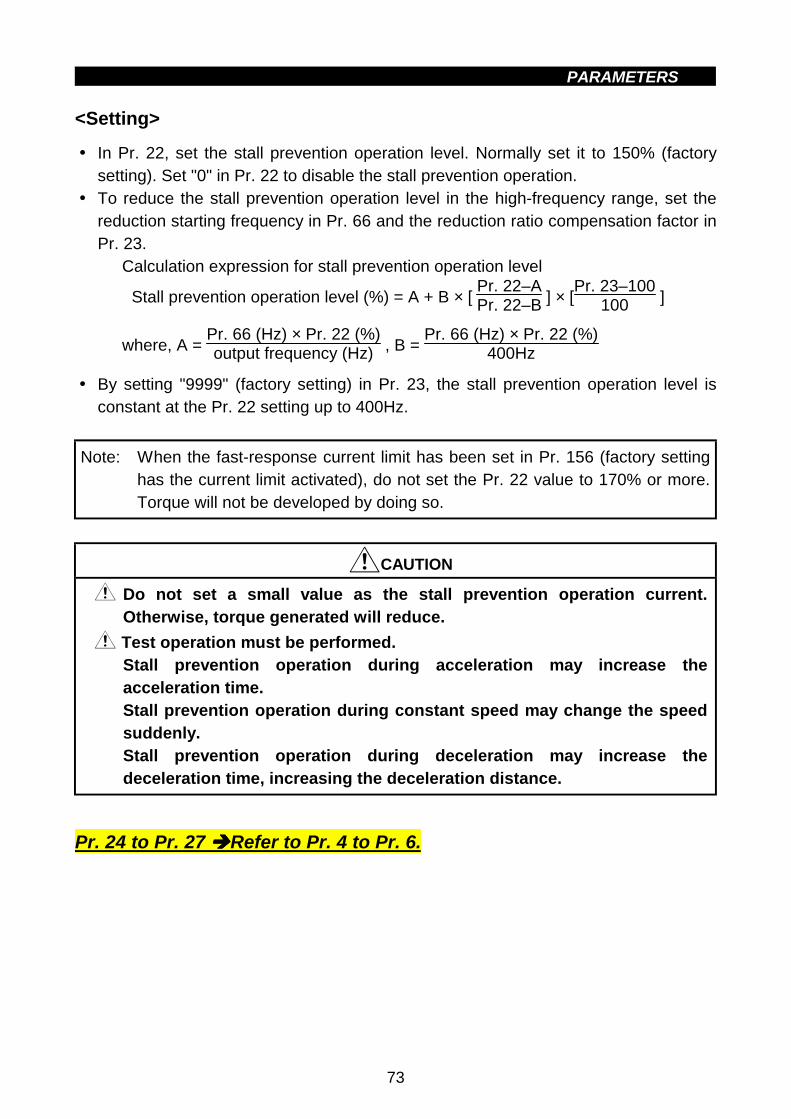
PARAMETERS
73
<Setting>
! In Pr. 22, set the stall prevention operation level. Normally set it to 150% (factorysetting). Set "0" in Pr. 22 to disable the stall prevention operation.
! To reduce the stall prevention operation level in the high-frequency range, set thereduction starting frequency in Pr. 66 and the reduction ratio compensation factor inPr. 23.
Calculation expression for stall prevention operation level
Stall prevention operation level (%) = A + B × [ Pr. 22–APr. 22–B ] × [
Pr. 23–100100 ]
where, A = Pr. 66 (Hz) × Pr. 22 (%)output frequency (Hz) , B =
Pr. 66 (Hz) × Pr. 22 (%)400Hz
! By setting "9999" (factory setting) in Pr. 23, the stall prevention operation level isconstant at the Pr. 22 setting up to 400Hz.
Note: When the fast-response current limit has been set in Pr. 156 (factory settinghas the current limit activated), do not set the Pr. 22 value to 170% or more.Torque will not be developed by doing so.
CAUTION
Do not set a small value as the stall prevention operation current.Otherwise, torque generated will reduce.
Test operation must be performed.Stall prevention operation during acceleration may increase theacceleration time.Stall prevention operation during constant speed may change the speedsuddenly.Stall prevention operation during deceleration may increase thedeceleration time, increasing the deceleration distance.
Pr. 24 to Pr. 27 &&&&Refer to Pr. 4 to Pr. 6.

PARAMETERS
74
Pr. 3 "base frequency"Pr. 7 "acceleration time"Pr. 8 "deceleration time"Pr. 20 "acceleration/deceleration
reference frequency"Pr. 44 "second
acceleration/deceleration time"Pr. 45 "second deceleration
time"
Related parameters
" " Acceleration/deceleration pattern (Pr. 29)4.2.11 Acceleration/deceleration pattern (Pr. 29)
Pr. 29 "acceleration/deceleration pattern"
Set the acceleration/deceleration pattern.
ParameterNumber
FactorySetting
SettingRange
29 0 0, 1, 2
[Linear acceleration/deceleration]
Time
Set value 0
Ou
tput
freq
uen
cy(H
z)
fb
Time
[S-shaped acceleration/deceleration A]
Set value 1
Out
put
freq
uenc
y(H
z)
f1
Time
f2
[S-shaped acceleration/deceleration B]
Set value 2
Outp
ut
frequ
ency
(Hz)
<Setting>
Pr. 29 Setting Function Description
0Linearacceleration/deceleration
Linear acceleration/deceleration is made up/down to thepreset frequency (factory setting).
1
S-shapedacceleration/decelerationA(Note)
For machine tool spindlesThis setting is used when it is necessary to makeacceleration/deceleration in a short time up to the basefrequency or higher speed range.In this acceleration/deceleration pattern, fb (base frequency)is always the inflection point of an S shape, and you can setthe acceleration/deceleration time according to the reductionin motor torque in the base frequency or higher constant-output operation range.
2
S-shapedacceleration/decelerationB
For prevention of cargo collapse on conveyor, etc.This setting provides S-shaped acceleration/decelerationfrom f2 (current frequency) to f1 (target frequency), easingan acceleration/deceleration shock. This pattern has aneffect on the prevention of cargo collapse, etc.
Note: For the acceleration/deceleration time, set the time required to reach the"base frequency" in Pr. 3, not the "acceleration/deceleration referencefrequency" in Pr. 20. For details, refer to Pr. 7 and Pr. 8.
4

PARAMETERS
75
" Regenerative brake duty (Pr. 30, Pr. 70)4.2.12 Regenerative brake duty (Pr. 30, Pr. 70)
Pr. 30 "regenerative function selection"
Pr. 70 "special regenerative brake duty"
! When making frequent starts/stops, use the optional "brake resistor" to increase theregenerative brake duty. (0.4K or more)
ParameterNumber
FactorySetting
SettingRange
30 0 0,170 0% 0 to 30%
<Setting>
(1) When using the brake resistor (MRS), brake unit, high power factorconverter
! Set "0" in Pr. 30.! The Pr. 70 setting is made invalid.
(2) When using the brake resistors (2 MYSs in parallel) (3.7K is onlyallowed)
! Set "1" in Pr. 30.! Set "6%" in Pr. 70.
(3) When using the high-duty brake resistor (FR-ABR)
! Set "1" in Pr. 30.! Set "10%" in Pr. 70.
Note:1. Pr. 70 "regenerative brake duty" indicates the %ED of the built-in braketransistor operation. The setting should not be higher than the permissiblevalue of the brake resistor used. Otherwise, the resistor can overheat.
2. When Pr. 30 = "0", Pr. 70 is not displayed but the brake duty is fixed at 3%.(Fixed at 2% for 5.5K, 7.5K)
3. The brake resistor cannot be connected to 0.1K and 0.2K inverters.
WARNING
The value set in Pr. 70 should not exceed the value set to the brakeresistor used.Otherwise, the resistor can overheat.

PARAMETERS
76
" " Frequency jump (Pr. 31 to Pr. 36)4.2.13 Frequency jump (Pr. 31 to Pr. 36)
Pr. 31 "frequency jump 1A"
Pr. 32 "frequency jump 1B"
Pr. 33 "frequency jump 2A"
Pr. 34 "frequency jump 2B"
Pr. 35 "frequency jump 3A"
Pr. 36 "frequency jump 3B"
! When it is desired to avoid resonance attributable to the natural frequency of amechanical system, these parameters allow resonant frequencies to be jumped. Upto three areas may be set, with the jump frequencies set to either the top or bottompoint of each area.
! The value set to 1A, 2A or 3A is a jump point and operation is performed at thisfrequency.
ParameterNumber
FactorySetting
Setting Range Remarks
31 9999 0 to 400Hz, 9999 9999: Function invalid32 9999 0 to 400Hz, 9999 9999: Function invalid33 9999 0 to 400Hz, 9999 9999: Function invalid34 9999 0 to 400Hz, 9999 9999: Function invalid35 9999 0 to 400Hz, 9999 9999: Function invalid36 9999 0 to 400Hz, 9999 9999: Function invalid
Pr.31Pr.32
Pr.33Pr.34
Pr.35Pr.36
Frequency jump
Run
nin
g fr
eq
uency
(H
z)
<Setting>
! To fix the frequency at 30Hz between Pr. 33 andPr. 34 (30Hz and 35Hz), set 35Hz in Pr. 34 and30Hz in Pr. 33.
! To jump to 35Hz between 30 and 35Hz, set 35Hz inPr. 33 and 30Hz in Pr. 34.
Note:1. During acceleration/deceleration, the running frequency within the set area isvalid.
Pr.34:35HzPr.33:30Hz
Pr.33:35HzPr.34:30Hz
4

PARAMETERS
77
Pr. 52 "PU main display dataselection"
Related parameter
" " Speed display (Pr. 37)4.2.14 Speed display (Pr. 37)
Pr. 37 "speed display"
The unit of the output frequency display of the parameter unit (FR-PU04) can bechanged from the frequency to the motor speed or machine speed.
ParameterNumber
FactorySetting
SettingRange
Remarks
37 00, 0.01 to
99980: Outputfrequency
<Setting>
! To display the machine speed, set in Pr. 37 the machine speed for 60Hz operation.
Note:1. The motor speed is converted into the output frequency and does not matchthe actual speed.
2. To change the parameter unit (FR-PU04) monitor (PU main display), refer toPr. 52.
3. Only the PU monitor display uses the unit set in this parameter. Set the otherspeed-related parameters (e.g. Pr. 1) in the frequency unit.
4. Due to the restrictions of the resolution of the set frequency, the displayedvalue may be different from the setting for the second decimal place.
CAUTION
Make sure that the running speed setting is correct.Otherwise, the motor might run at extremely high speed, damaging themachine.

PARAMETERS
78
" " Frequency at 5V (10V) input (Pr. 38)" " Up-to-frequency sensitivity (Pr. 41)4.2.15 Up-to-frequency sensitivity (Pr. 41)
Pr. 41 "up-to-frequency sensitivity"
The ON range of the up-to-frequency signal (SU) output when the output frequencyreaches the running frequency can be adjusted between 0 and ±100% of the runningfrequency.This parameter can be used to ensure that the running frequency has been reached orused as the operation start signal etc. for related equipment.
ParameterNumber
FactorySetting
SettingRange
41 10% 0 to 100%
Output signal SU ON
Pr.41
Time
OFFOFF
Adjustable rangeRunning frequency
Outp
ut
frequen
cy (
Hz)
! Use Pr. 192 to allocate the terminal used for SU signal output.Refer to page 120 for Pr. 192 "A, B, C terminal (ABC) function selection".
! The DeviceNet output is the 3-bit inverter status.
Note: When terminal assignment is changed using Pr. 192, the other functions maybe affected. Check the functions of the corresponding terminals beforemaking settings.
4.2.16 Output frequency detection (Pr. 42, Pr. 43)" Output frequency detection (Pr. 42, Pr. 43)
Pr. 42 "output frequency detection"
Pr. 43 "output frequency detectionfor reverse rotation"
The output frequency detection signal (FU) is output when the output frequencyreaches or exceeds the setting. This function can be used for electromagnetic brakeoperation, open signal etc.
! You can also set the detection of the frequency used exclusively for reverse rotation.This function is effective for switching the timing of electromagnetic brake operationbetween forward rotation (rise) and reverse rotation (fall) during vertical lift operationetc.
ParameterNumber
FactorySetting
Setting Range Remarks
42 6Hz 0 to 400Hz43 9999 0 to 400Hz, 9999 9999: Same as Pr. 42 setting
Pr. 192 "A, B, C terminal (ABC)function selection"
Related parameters
Pr. 192 "A, B, C terminal (ABC)function selection"
Related parameters
4

PARAMETERS
79
<Setting>
Refer to the figure below and set the corresponding parameters:! When Pr. 43 ≠ 9999, the Pr. 42 setting applies to forward rotation and the Pr. 43
setting applies to reverse rotation.! Assign the terminal used for FU signal output with Pr. 192 "A, B, C terminal (ABC)
function selection".Refer to page 120 for Pr. 192 "A, B, C terminal (ABC) function selection".
! The DeviceNet output is the 6-bit inverter status.
Pr.42
Pr.43
Outp
ut
freq
uency
(H
z)
Output signalFU
Time
OFF
ON
OFF
ON
OFF
Reverserotation
Forwardrotation
Note: Changing the terminal assignment using Pr. 192 may affect the otherfunctions. Make setting after confirming the function of each terminal.
Pr. 44, Pr. 45 &&&&Refer to Pr. 7.
Pr. 46 &&&&Refer to Pr. 0.
Pr. 47 &&&&Refer to Pr. 3.
Pr. 48 &&&&Refer to Pr. 9.
" Monitor display (Pr. 52, Pr. 54)4.2.17 Monitor display (Pr. 52)
Pr. 52 "PU main display data selection"
You can select the signals shown on the parameter unit (FR-PU04) main displayscreen.
ParameterNumber
FactorySetting
SettingRange
52 0 0, 23, 100
Pr. 37 "speed display"Pr. 171 "actual operation hour
meter clear"
Related parameters

PARAMETERS
80
<Setting>
Set Pr. 52 and Pr. 54 in accordance with the following table:
Parameter SettingPr. 52Signal Type Unit
PU main monitorOutputfrequency
Hz 0/100
Output current A 0/100Output voltage 0/100Alarm display 0/100Actualoperation time
10h 23
When 100 is set in Pr. 52, the monitored values during stop and during operation differas indicated below:
Pr. 520 100
Duringoperation/during stop
During stop During operation
Outputfrequency
Output frequency Set frequency Output frequency
Output current Output currentOutput voltage Output voltageAlarm display Alarm display
Note:1. During an error, the output frequency at error occurrence is displayed.2. During MRS, the values are the same as during a stop.
During offline auto tuning, the tuning status monitor has priority.
Note:1. By setting "0" in Pr. 52, the monitoring of "output frequency to alarm display"can be selected in sequence by the SHIFT key of the PU.
2. The actual operation time displayed by setting "23" in Pr. 52 is calculatedusing the inverter operation time. (Inverter stop time is not included.) Set "0"in Pr. 171 to clear it.
3. The actual operation time is calculated from 0 to 99990 hours, then cleared,and recalculated from 0. If the operation time is less than 10 hours there isno display.
4. The actual operation time is not calculated if the inverter has not operatedfor more than 1 hour continuously.
4

PARAMETERS
81
" " Monitoring reference (Pr. 55, Pr. 56)" " Automatic restart after instantaneous power failure (Pr. 57, Pr. 58)4.2.18 Automatic restart after instantaneous power failure
(Pr. 57, Pr. 58)
Pr. 57 "restart coasting time"
Pr. 58 "restart cushion time"! You can restart the inverter without stopping the motor (with the motor coasting)
when power is restored after an instantaneous power failure.
ParameterNumber
FactorySetting
Setting Range Remarks
57 9999 0 to 5 s, 9999 9999: No restart58 1.0 s 0 to 60 s
<Setting>Refer to the following table and set the parameters:
ParameterNumber
Setting Description
0.1K to 1.5K 0.5 s coasting time0
2.2K to 7.5K 1.0 s coasting timeGenerally use this setting.
0.1 to 5 s
Waiting time for inverter-triggered restart after power is restoredfrom an instantaneous power failure. (Set this time between 0.1sand 5s according to the inertia moment (J) and torque of theload.)
57
9999 No restart
58 0 to 60 sNormally the inverter may be run with the factory settings. Thesevalues are adjustable to the load (inertia moment, torque).
Pr. 58 setting
Instantaneous power failure (power failure) time
Power supply (R(L1), S(L2), T(L3))
STF(STR)
Motor speed(r/min)
Inverter output frequency(Hz)
Inverter output voltage(V)
Coasting time
Pr. 57 setting
Restart voltage rise time

PARAMETERS
82
Pr. 7 "acceleration time"Pr. 8 "deceleration time"
Related parameters
Note:1. Automatic restart after instantaneous power failure uses a reduced-voltagestarting system in which the output voltage is raised gradually with the presetfrequency unchanged, independently of the coasting speed of the motor.As in the FR-A024/044, a motor coasting speed detection system (speedsearch system) is not used but the output frequency before an instantaneouspower failure is output. Therefore, if the instantaneous power failure time islonger than 0.2s, the frequency before the instantaneous power failurecannot be stored and the inverter will start at 0Hz.
2. The SU and FU signals are not output during restart but are output after therestart cushion time has elapsed.
CAUTION
When automatic restart after instantaneous power failure has beenselected, the motor and machine will start suddenly (after the reset timehas elapsed) after occurrence of an instantaneous power failure.Stay away from the motor and machine.When you have selected automatic restart after instantaneous powerfailure, apply the supplied CAUTION seals in easily visible places.When the start signal is turned off or the STOP
RESET key of the PU is pressedduring the cushion time for automatic restart after instantaneous powerfailure, deceleration starts after the automatic restart cushion time set inPr. 58 "cushion time for automatic restart after instantaneous powerfailure" has elapsed.
4.2.19 Shortest acceleration/deceleration mode (Pr. 60 to Pr. 63)
Pr. 60 "shortest acceleration/deceleration mode"
Pr. 61 "reference I for intelligent mode"
Pr. 62 "ref. I for intelligent mode accel"
Pr. 63 "ref. I for intelligent mode decel"
The inverter automatically sets appropriate parameters for operation.! If you do not set the acceleration and deceleration times and V/F pattern, you can
run the inverter as if appropriate values had been set in the correspondingparameters. This operation mode is useful to start operation immediately withoutmaking fine parameter settings.
ParameterNumber
FactorySetting
Setting Range Remarks
60 0 0, 1, 2, 11, 12
61 9999 0 to 500A, 99999999: Referenced from ratedinverter current.
62 9999 0 to 200%, 999963 9999 0 to 200%, 9999
4

PARAMETERS
83
< Setting>
Pr. 60Setting
OperationMode
DescriptionAutomatically
SetParameters
0Ordinaryoperationmode
1, 2, 11,12
Shortestacceleration/decelerationmode
Set to accelerate/decelerate the motor in theshortest time.The inverter makes acceleration/deceleration inthe shortest time using its full capabilities. Duringdeceleration, an insufficient brake capability maycause the regenerative overvoltage alarm(E.OV3)."1" : Stall prevention operation level 150%"2" : Stall prevention operation level 180%"11": Stall prevention operation level 150%
when brake resistor or brake unit is used"12": Stall prevention operation level 180%
when brake resistor or brake unit is used
Pr. 7, Pr. 8
<Setting 2>
! Set these parameters to improve performance in the intelligent mode.
(1) Pr. 61 "reference I for intelligent mode"
Setting Reference Current9999 (factory setting) Referenced from rated inverter current0 to 500A Referenced from setting (rated motor current)
(2) Pr. 62 "ref. I for intelligent mode accel"
The reference current setting can be changed.
Setting Reference Current9999 (factory setting) 150% (180%) is the limit value.0 to 200% The setting of 0 to 200% is the limit value.
(3) Pr. 63 "ref. I for intelligent mode decel"
The reference current setting can be changed.
Setting Reference Current9999 (factory setting) 150% (180%) is the limit value.0 to 200% The setting of 0 to 200% is the limit value.
Note: Pr. 61 to Pr. 63 are only valid when any of "1, 2, 11, 12" are selected forPr. 60.

PARAMETERS
84
" " Retry function (Pr. 65, Pr. 67, Pr. 68, Pr. 69)4.2.20 Retry function (Pr. 65, Pr. 67 to Pr. 69)
Pr. 65 "retry selection"
Pr. 67 "number of retries at alarm occurrence"
Pr. 68 "retry waiting time"
Pr. 69 "retry count display erasure"
When any protective function (major fault) is activated and the inverter stops its output,the inverter itself resets automatically and performs retries. You can select whetherretry is made or not, alarms reset for retry, number of retries made, and waiting time.
ParameterNumber
FactorySetting
Setting Range
65 0 0 to 367 0 0 to 10, 101 to 11068 1 s 0.1 to 360 s69 0 0
<Setting>
Use Pr. 65 to select the protective functions (major faults) which execute retry.
Errors Reset for Retry SettingFunction name 0 1 2 3
During acceleration (OC1) " " "During constant speed (OC2) " " "Overcurrent shut-offDuring decelerationDuring stop (OC3) " " "During acceleration (OV1) " " "During constant speed (OV2) " " "Regenerative overvoltage
shut-off During decelerationDuring stop (OV3) " " "
Motor (THM) "Overload shut-off(Electronic overcurrentprotection) Inverter (THT) "Fin overheat (FIN)Brake transistor fault detection (BE) "Output side ground fault overcurrent protection (GF) "External thermal relay operation (OHT) "Power limit stall prevention (OLT) "Communication error (OPT) "Parameter error (PE) "PU disconnection occurrence (PUE)Retry count exceeded (RET)CPU error (CPU)
Note: " indicates the retry items selected.
4

PARAMETERS
85
Use Pr. 67 to set the number of retries at alarm occurrence.
Pr. 67 Setting Number of Retries Alarm Signal Output0 Retry is not made.
1 to 10 1 to 10 times Not output.101 to 110 1 to 10 times Output.
! Use Pr. 68 to set the waiting time from when an inverter alarm occurs until a restartin the range 0.1 to 360 seconds.
! Reading the Pr. 69 value provides the cumulative number of successful restarttimes made by retry. The setting of "0" erases the cumulative number of times.
Note:1. The cumulative number in Pr. 69 is incremented by "1" when retry operationis regarded as successful, i.e. when normal operation is continued withoutthe protective function (major fault) activated during a period five timeslonger than the time set in Pr. 68.
2. If the protective function (major fault) is activated consecutively within aperiod five times longer than the above waiting time, the parameter unit(FR-PU04) may show data different from the first retry data. The data storedas the error reset for retry is only that of the protective function (major fault)which was activated the first time.
3. When an inverter alarm is reset by the retry function at the retry time, thestored data of the electronic over current protection, etc. are not cleared.(Different from the power-on reset.)
CAUTION
When you have selected the retry function, stay away from the motor andmachine unless required. They will start suddenly (after the reset timehas elapsed) after occurrence of an alarm.When you have selected the retry function, apply the supplied CAUTIONseals in easily visible places.
Pr. 66 &&&&Refer to Pr. 22.
Pr. 70 &&&&Refer to Pr. 30.

PARAMETERS
86
Pr. 0 "torque boost"Pr. 12 "DC injection brake voltage"Pr. 19 "base frequency voltage"Pr. 80 "motor capacity"Pr. 96 "auto-tuning setting/status"
Related parameters
" " 4.2.21 Applied motor (Pr. 71)
Pr. 71 "applied motor"
Set the motor used.! When using the Mitsubishi constant-torque motor, set "1" in Pr. 71 for either V/F
control or general-purpose magnetic flux vector control.The electronic overcurrent protection is set to the thermal characteristic of theconstant-torque motor.
ParameterNumber
FactorySetting
Setting Range
71 00, 1, 3, 5, 6, 13, 15, 16, 23, 100, 101,
103, 105, 106, 113, 115, 116, 123
<Setting>! Refer to the following list and set this parameter according to the motor used.
Applied motorPr. 71
SettingThermal Characteristics of Electronic
Overcurrent Protection StandardConstant-
Torque0, 100 Thermal characteristics matching a standard motor '
1, 101Thermal characteristics matching the Mitsubishiconstant-torque motor
'
3, 103 Standard motor '13, 113 Constant-torque motor '
23, 123Mitsubishi general-purpose motor SF-JR4P (1.5kW or less)
Select "offline auto tuningsetting".
'
5, 105 Standard motor '15, 115 Constant-torque motor
Starconnection '
6, 106 Standard motor '16, 116 Constant-torque motor
Deltaconnection
Motorconstants canbe entereddirectly. '
By setting any of "100 to 123", the electronic overcurrent protection thermal characteristic(applied motor) can be changed as indicated below according to the ON/OFF status of the RTsignal:
RT Signal Electronic Overcurrent Protection Thermal Characteristic (Applied Motor)OFF As indicated in the above tableON Constant-torque motor
CAUTION
Set this parameter correctly according to the motor used.Incorrect setting may cause the motor to overheat and burn.
4

PARAMETERS
87
" Applied motor (Pr. 71)" " PWM carrier frequency (Pr. 72, Pr. 240)4.2.22 PWM carrier frequency (Pr. 72, Pr. 240)
Pr. 72 "PWM frequency selection"
Pr. 240 "Soft-PWM setting"
You can change the motor tone.! By parameter setting, you can select Soft-PWM control which changes the motor
tone.! Soft-PWM control changes motor noise from a metallic tone into an unoffending
complex tone.
ParameterNumber
FactorySetting
SettingRange
Remarks
72 1 0 to 15 0 : 0.7kHz,15 : 14.5kHz
240 1 0, 1 1: Soft-PWM valid
<Setting>
! Refer to the following list and set the parameters:
ParameterNumber
Setting Description
72 0 to 15PWM carrier frequency can be changed.The setting displayed is in [kHz].Note that 0 indicates 0.7kHz and 15 indicates 14.5kHz.
0 Soft-PWM invalid240
1 When any of "0 to 5" is set in Pr. 72, Soft-PWM is made valid.
Note:1. Note that when the inverter is run at the ambient temperature above 40°Cwith a 2kHz or higher value set in Pr. 72, the rated output current of theinverter must be reduced. (Refer to page 149.)
2. An increased PWM frequency will decrease motor noise but noise andleakage current will increase. Take proper action (Refer to pages 37 to 41).
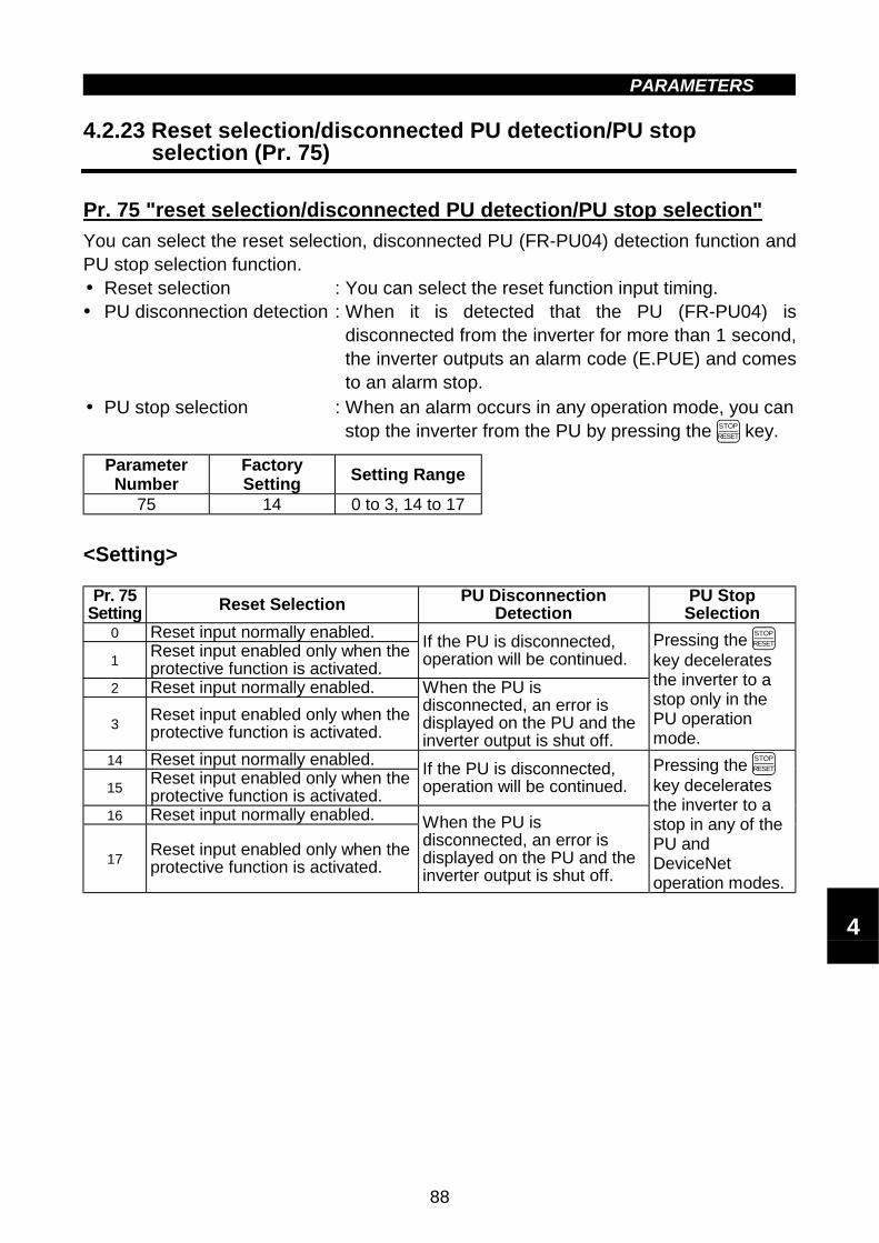
PARAMETERS
88
" " Voltage input (Pr. 73)" Reset selection/disconnected PU detection/PU stop selection (Pr. 75)4.2.23 Reset selection/disconnected PU detection/PU stop selection (Pr. 75)
Pr. 75 "reset selection/disconnected PU detection/PU stop selection"
You can select the reset selection, disconnected PU (FR-PU04) detection function andPU stop selection function.! Reset selection : You can select the reset function input timing.! PU disconnection detection : When it is detected that the PU (FR-PU04) is
disconnected from the inverter for more than 1 second,the inverter outputs an alarm code (E.PUE) and comesto an alarm stop.
! PU stop selection : When an alarm occurs in any operation mode, you canstop the inverter from the PU by pressing the STOP
RESET key.
ParameterNumber
FactorySetting
Setting Range
75 14 0 to 3, 14 to 17
<Setting>
Pr. 75Setting Reset Selection PU Disconnection
DetectionPU Stop
Selection0 Reset input normally enabled.
1Reset input enabled only when theprotective function is activated.
If the PU is disconnected,operation will be continued.
2 Reset input normally enabled.
3Reset input enabled only when theprotective function is activated.
When the PU isdisconnected, an error isdisplayed on the PU and theinverter output is shut off.
Pressing the STOP
RESET
key deceleratesthe inverter to astop only in thePU operationmode.
14 Reset input normally enabled.
15Reset input enabled only when theprotective function is activated.
If the PU is disconnected,operation will be continued.
16 Reset input normally enabled.
17Reset input enabled only when theprotective function is activated.
When the PU isdisconnected, an error isdisplayed on the PU and theinverter output is shut off.
Pressing the STOP
RESET
key deceleratesthe inverter to astop in any of thePU andDeviceNetoperation modes.
4

PARAMETERS
89
How to make a restart after a stop by the STOP
RESET key on the PU
Parameter unit (FR-PU04)1) After completion of deceleration to a stop, switch off the STF or STR signal.2) Press the EXT key.3) Switch on the STF or STR signal.
Stop and restart example for DeviceNet operation
STF ON(STR) OFF
Time
Parameter unit(FR-PU04)
Spe
ed
key
key
SET
STOP
RESET
The other way of making a restart other than the above method is to perform a power-reset or to make a reset with the inverter reset terminal.
Note:1. By entering the reset signal (RES) during operation, the inverter shuts offoutput while it is reset, the data of the electronic overcurrent protection andregenerative brake duty are reset, and the motor coasts.
2. The PU disconnection detection function judges that the PU is disconnectedwhen it is removed from the inverter for more than 1 second. If the PU hadbeen disconnected before power-on, it is not judged as an alarm.
3. To resume operation, reset the inverter after confirming that the PU isconnected securely.
4. The Pr. 75 value can be set any time. Also, if parameter (all) clear isexecuted, this setting will not return to the initial value.
5. When the inverter is stopped by the PU stop function, PS is displayed but analarm is not output.When the PU connector is used for RS-485 communication operation, thereset selection and PU stop selection functions are valid but the PUdisconnection detection function is invalid.
CAUTION
Do not reset the inverter with the start signal on.Otherwise, the motor will start instantly after resetting, leading topotentially hazardous conditions.

PARAMETERS
90
Pr. 79 "operation mode selection"
Related parameters
Pr. 79 "operation mode selection"Related parameters
4.2.24 Parameter write inhibit selection (Pr. 77)
Pr. 77 "parameter write disable selection"
You can select between write-enable and disable for parameters. This function is usedto prevent parameter values from being rewritten by incorrect operation.
ParameterNumber
FactorySetting
Setting Range
77 0 0, 2
<Setting>
Pr. 77Setting
Function
0Parameter values may only be written while the inverter isat a stop in the PU or DeviceNet operation mode. (Note 1)
2 Write enabled even while the inverter is running.
Note:1. The parameters half-tone screened in the parameter list can be set at anytime.
2. If Pr. 77 = 2, the values of Pr. 23, Pr. 66, Pr. 71, Pr. 79, Pr. 80, Pr. 83, Pr. 84,Pr. 96, Pr. 180 to Pr.183 and Pr. 190 to Pr. 192 cannot be written duringoperation. Stop operation when changing their parameter settings.
3. When the parameter unit (FR-PU04) is used, setting "1" in Pr. 77 can inhibitparameter write. At this time, values may be written to Pr. 75, Pr. 77 andPr. 79.Parameter clear and parameter all clear are also be inhibited.
" Reverse rotation prevention selection (Pr. 78)4.2.25 Reverse rotation prevention selection (Pr. 78)
Pr. 78 "reverse rotation preventionselection"
This function can prevent any reverse rotation fault resulting from the incorrect input ofthe start signal.! Used for a machine which runs only in one direction, e.g. fan, pump.
(The setting of this function is valid for the PU and DeviceNet operations.)
ParameterNumber
FactorySetting
SettingRange
78 0 0, 1, 2
<Setting>Pr. 78 Setting Function
0Both forward and reverserotations allowed
1 Reverse rotation disallowed2 Forward rotation disallowed
4

PARAMETERS
91
Pr. 4 to Pr. 6, Pr. 24 to Pr. 27,Pr. 232 to Pr. 239
(multi-speed operation)Pr. 180 to Pr. 183
(input terminal (DeviceNet input) function selection)
Related parameters
" " Operation mode selection (Pr. 79)4.2.26 Operation mode selection (Pr. 79)
Pr. 79 "operation mode selection"
Used to select the operation mode of the inverter.The inverter can be run from the parameter unit(PU operation) and DeviceNet signals (DeviceNetoperation).When power is switched on (factory setting), the DeviceNet operation mode isselected.
ParameterNumber
FactorySetting
SettingRange
79 2 0 to 2
<Setting>
In the following table, operation using the parameter unit is abbreviated to PUoperation.
Pr. 79Setting Function
0When power is switched on, the DeviceNet operation mode is selected.
PU or DeviceNet operation can be selected by pressing the PU / EXT keys of the
parameter unit. For these modes, refer to the setting 1 and 2 below.Operation mode Running frequency Start signal
1 PU operationmode (PU)
Digital setting by the keyoperation of parameter unit
FWD or REV key of parameter
unit
2DeviceNetoperation mode(NET)
DeviceNet master unit

PARAMETERS
92
Pr. 71 "applied motor"Pr. 83 "rated motor voltage"Pr. 84 "rated motor frequency"Pr. 96 "auto-tuning setting/status"
Related parameters
4.2.27 General-purpose magnetic flux vector control selection (Pr. 80)
Pr. 80 "motor capacity"
You can set the general-purpose magnetic flux vector control." General-purpose magnetic flux vector control
Provides large starting torque and sufficient low-speed torque.If the motor constants vary slightly, stable, large low-speed torque is providedwithout specific motor constant setting or tuning.
ParameterNumber
FactorySetting
Setting Range Remarks
80 99990.1kW to 7.5kW,
99999999: V/F control
If any of the following conditions are not satisfied, faults such as torque shortage andspeed fluctuation may occur. In this case, select V/F control.
<Operating conditions>
! The motor capacity is equal to or one rank lower than the inverter capacity.! The number of motor poles is any of 2, 4, and 6. (4 poles only for the constant-
torque motor)! Single-motor operation (one motor for one inverter) is performed.! The wiring length between the inverter and motor is within 30m. (If the length is over
30m, perform offline auto tuning with the cables wired.)
<Setting>
(1) General-purpose magnetic flux vector control! The general-purpose magnetic flux vector control can be selected by setting the
capacity of the motor used in Pr. 80.
ParameterNumber
Setting Description
9999 V/F control
800.1 to 7.5 Set the motor capacity applied.
General-purposemagnetic fluxvector control
! When using Mitsubishi's constant-torque motor (SF-JRCA), set "1" in Pr. 71. (Whenusing the SF-JRC, perform the offline auto tuning .)
4
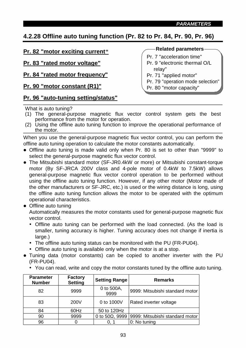
PARAMETERS
93
Pr. 7 "acceleration time"Pr. 9 "electronic thermal O/L
relay"Pr. 71 "applied motor"Pr. 79 "operation mode selection"Pr. 80 "motor capacity"
Related parameters
" " Offline auto tuning function (Pr. 82 to Pr. 84, Pr. 90, Pr. 96)4.2.28 Offline auto tuning function (Pr. 82 to Pr. 84, Pr. 90, Pr. 96)
Pr. 82 "motor exciting current"
Pr. 83 "rated motor voltage"
Pr. 84 "rated motor frequency"
Pr. 90 "motor constant (R1)"
Pr. 96 "auto-tuning setting/status"
What is auto tuning?(1) The general-purpose magnetic flux vector control system gets the best
performance from the motor for operation.(2) Using the offline auto tuning function to improve the operational performance of
the motor.
When you use the general-purpose magnetic flux vector control, you can perform theoffline auto tuning operation to calculate the motor constants automatically." Offline auto tuning is made valid only when Pr. 80 is set to other than "9999" to
select the general-purpose magnetic flux vector control." The Mitsubishi standard motor (SF-JR0.4kW or more) or Mitsubishi constant-torque
motor (By SF-JRCA 200V class and 4-pole motor of 0.4kW to 7.5kW) allowsgeneral-purpose magnetic flux vector control operation to be performed withoutusing the offline auto tuning function. However, if any other motor (Motor made ofthe other manufacturers or SF-JRC, etc.) is used or the wiring distance is long, usingthe offline auto tuning function allows the motor to be operated with the optimumoperational characteristics.
" Offline auto tuningAutomatically measures the motor constants used for general-purpose magnetic fluxvector control.! Offline auto tuning can be performed with the load connected. (As the load is
smaller, tuning accuracy is higher. Tuning accuracy does not change if inertia islarge.)
! The offline auto tuning status can be monitored with the PU (FR-PU04).! Offline auto tuning is available only when the motor is at a stop.
" Tuning data (motor constants) can be copied to another inverter with the PU(FR-PU04).! You can read, write and copy the motor constants tuned by the offline auto tuning.
ParameterNumber
FactorySetting
Setting Range Remarks
82 99990 to 500A,
99999999: Mitsubishi standard motor
83 200V 0 to 1000V Rated inverter voltage
84 60Hz 50 to 120Hz90 9999 0 to 50Ω, 9999 9999: Mitsubishi standard motor96 0 0, 1 0: No tuning
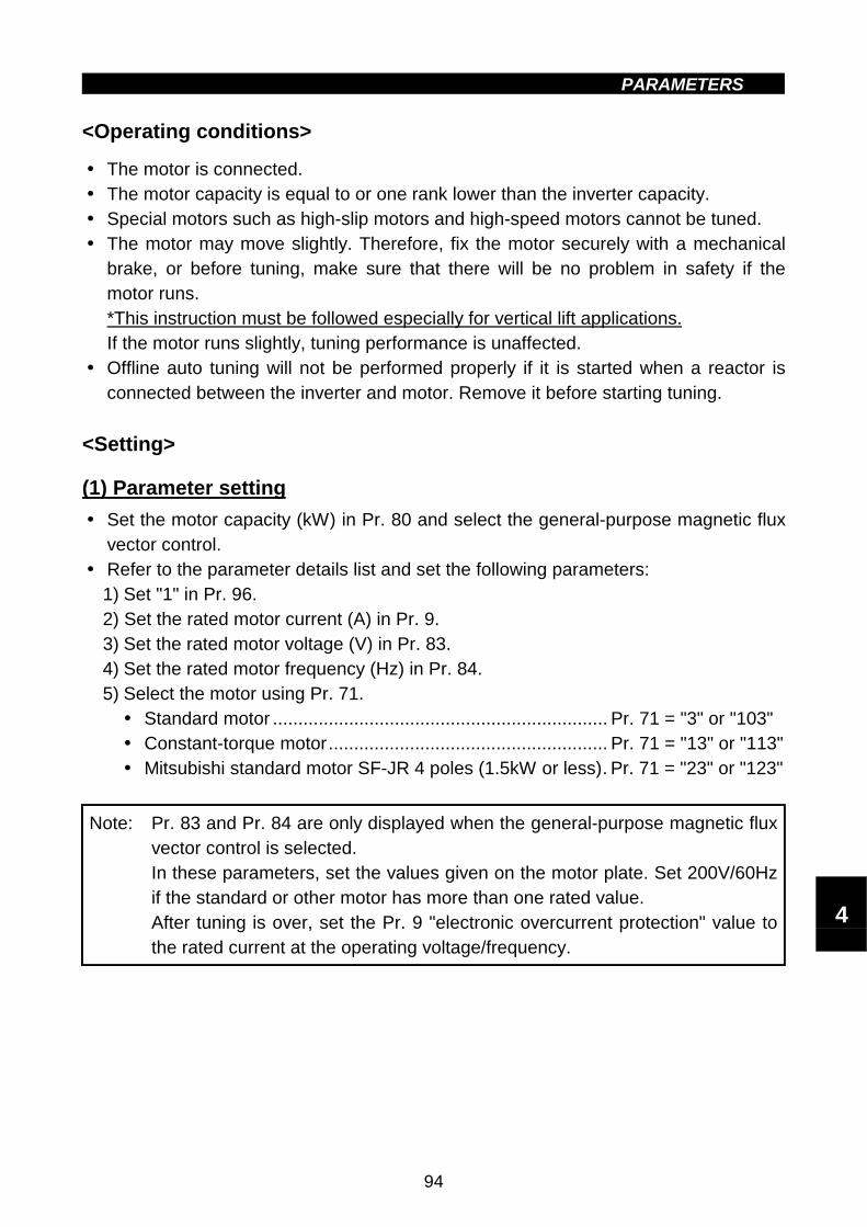
PARAMETERS
94
<Operating conditions>
! The motor is connected.! The motor capacity is equal to or one rank lower than the inverter capacity.! Special motors such as high-slip motors and high-speed motors cannot be tuned.! The motor may move slightly. Therefore, fix the motor securely with a mechanical
brake, or before tuning, make sure that there will be no problem in safety if themotor runs.*This instruction must be followed especially for vertical lift applications.If the motor runs slightly, tuning performance is unaffected.
! Offline auto tuning will not be performed properly if it is started when a reactor isconnected between the inverter and motor. Remove it before starting tuning.
<Setting>
(1) Parameter setting
! Set the motor capacity (kW) in Pr. 80 and select the general-purpose magnetic fluxvector control.
! Refer to the parameter details list and set the following parameters:1) Set "1" in Pr. 96.2) Set the rated motor current (A) in Pr. 9.3) Set the rated motor voltage (V) in Pr. 83.4) Set the rated motor frequency (Hz) in Pr. 84.5) Select the motor using Pr. 71.
! Standard motor .................................................................. Pr. 71 = "3" or "103"! Constant-torque motor....................................................... Pr. 71 = "13" or "113"! Mitsubishi standard motor SF-JR 4 poles (1.5kW or less). Pr. 71 = "23" or "123"
Note: Pr. 83 and Pr. 84 are only displayed when the general-purpose magnetic fluxvector control is selected.In these parameters, set the values given on the motor plate. Set 200V/60Hzif the standard or other motor has more than one rated value.After tuning is over, set the Pr. 9 "electronic overcurrent protection" value tothe rated current at the operating voltage/frequency.
4

PARAMETERS
95
(((( Parameter details
ParameterNumber
Setting Description
9 0 to 500A Set the rated motor current (A).0, 100 Thermal characteristics suitable for standard motor
1, 101Thermal characteristics suitable for Mitsubishi's constant-torque motor
3, 103 Standard motor13, 113 Constant-torque motor
23, 123Mitsubishi's SF-JR4P standard motor(1.5kW or less)
Select "offline autotuning setting"
5, 105 Standard motor15, 115 Constant-torque motor
Star connection
6, 106 Standard motor
71 (Note)
16, 116 Constant-torque motorDelta connection
Direct input ofmotor constantsenabled
83 0 to 1000V Set the rated motor voltage (V).84 50 to 120Hz Set the rated motor frequency (Hz).
90 0 to 50Ω, 9999Tuning data(Values measured by offline auto tuning are set automatically.)
0 Offline auto tuning is not performed.96
1 Offline auto tuning is performed.
Note: The electronic overcurrent protection characteristics are also selectedsimultaneously. By setting any of "100 to 123", the electronic overcurrentprotection changes to the thermal characteristic of the constant-torque motorwhen the RT signal switches on.
(2) Tuning execution
! For PU operation, press the FWD or REV key of the PU.! For DeviceNet operation, switch on the run command.
Note:1. To force tuning to end! Switch on the MRS or RES signal or press the STOP
RESET key to end of the PU.! Switch off the tuning start command to make a forced end.
2. During offline auto tuning, only the following I/O signals are valid:! Input signals
<Valid signals>MRS, RES, STF, STR
! Output signalsRUN, A, B, C
3. Special caution should be exercised when a sequence has been designedto open the mechanical brake with the RUN signal.

PARAMETERS
96
(3) Monitoring the offline tuning status
! For confirmation on the DeviceNet master unit, check the Pr. 96 setting.1: setting, 2: tuning in progress, 3: completion, 8: forced end, 9: error-activated end
! When the parameter unit (FR-PU04) is used, the Pr. 96 value is displayed duringtuning on the main monitor as shown below:
! Parameter unit (FR-PU04) main monitor(For inverter trip)
1. Setting2. Tuning in
progress3. Completion
4. Error-activated end
Display 1STOP PU
2TUNE
STF FWD PU
3TUNECOMPLETIONSTF STOP PU
9TUNEERRORSTF STOP PU
! Reference: Offline auto tuning time (factory setting) is about 10 seconds.
(4) Ending the offline auto tuning
1) Confirm the Pr. 96 value.! Normal end: "3" is displayed.! Abnormal end: "9", "91", "92" or "93" is displayed.! Forced end: "8" is displayed.
2) When tuning ended normallyFor PU operation, press the STOP
RESET key of the PU. For DeviceNet operation, switch offthe start signal (STF or STR) once.This operation resets the offline auto tuning and the PU's monitor display returns tothe ordinary indication. (Without this operation, next operation cannot be done.)
3) When tuning was ended due to an errorOffline auto tuning did not end normally. (The motor constants have not been set.)Reset the inverter and start tuning all over again.
4

PARAMETERS
97
4) Error display definitions
Error Display Error Cause Remedy9 Inverter trip Make setting again.
91Current limit (stall prevention) function wasactivated.
Increaseacceleration/deceleration time.Set "1" in Pr. 156.
92Converter output voltage reached 75% ofrated value.
Check for fluctuation of powersupply voltage.
93 Calculation errorCheck the motor wiring andmake setting again.
No connection with motor will result in a calculation (93) error.
5) When tuning was forced to endA forced end occurs when you forced the tuning to end during tuning by switching offthe start signal (STF or STR) once in DeviceNet operation or by pressing the STOP
RESET keyin PU operation.In this case, the offline auto tuning has not ended normally.(The motor constants are not set.)Reset the inverter and restart the tuning.
Note:1. The R1 motor constant measured during in the offline auto tuning is storedas a parameter and its data is held until the offline auto tuning is performedagain.
2. An instantaneous power failure occurring during tuning will result in a tuningerror.After power is restored, the inverter goes into the ordinary operation mode.Therefore, when STF (STR) is on, the motor runs in forward (reverse)rotation.
3. Any alarm occurring during tuning is handled as in the ordinary mode. Notethat if an error retry has been set, retry is ignored.
4. The set frequency monitor displayed during the offline auto tuning is 0Hz.
CAUTION
When the offline auto tuning is used in vertical lift application, e.g. a lifter,it may drop due to insufficient torque.

PARAMETERS
98
<Setting the motor constant as desired>
" To set the motor constant without using the offline auto tuning data
<Operating procedure>
1. Set any of the following values in Pr. 71:
Star ConnectionMotor
Delta ConnectionMotor
Standard motor 5 or 105 6 or 106Setting Constant-torque
motor15 or 115 16 or 116
By setting any of "105 to 116", the electronic overcurrent protection changes to thethermal characteristics of the constant-torque motor when the RT signal switches on.
2. Set "801" in Pr. 77.(Only when the Pr. 80 setting is other than "9999", the parameter values of themotor exciting current (Pr. 82) and motor constant (Pr. 90) can be displayed.Though the parameter values other than Pr. 82 and Pr. 90 can also be displayed,they are parameters for manufacturer setting and shall not be changed.)
3. In the parameter setting mode, read the following parameters and set desiredvalues:
ParameterNumber
Name Setting RangeSetting
IncrementsFactorySetting
82Motor exciting
current0 to 500A,
99990.01A 9999
90Motor constant
(R1)0 to 10Ω, 9999 0.001Ω 9999
4. Return the Pr. 77 setting to the original value.
5. Refer to the following table and set Pr. 84:
ParameterNumber
Name Setting RangeSetting
IncrementsFactorySetting
84Rated motor
frequency50 to 120Hz 0.01Hz 60Hz
Note:1. The Pr. 90 value may only be read when general-purpose magnetic fluxvector control has been selected.
2. Set "9999" in Pr. 90 to use the standard motor constant (including that forthe constant-torque motor).
3. If "star connection" is mistaken for "delta connection" or vice versa duringsetting of Pr. 71, general-purpose magnetic flux vector control cannot beexercised normally.
4

PARAMETERS
99
" Computer link operation (Pr. 117 to Pr. 124)4.2.29 Computer link operation (Pr. 117 to Pr. 124)
Pr. 117 "station number"Pr. 118 "communication speed"Pr. 119 "stop bit length"Pr. 120 "parity check presence/absence"Pr. 121 "number of communication retries"Pr. 122 "communication check time interval"Pr. 123 "waiting time setting"Pr. 124 "CR •••• LF presence/absence selection"Used to perform required settings for RS-485 communication between the inverter andpersonal computer."""" The motor can be run from the PU connector of the inverter using RS-485
communication.Communication specificationsConforming standard RS-485Number of inverters connected 1:N (maximum 32 inverters)Communication speed Selectable between 19200, 9600 and 4800bpsControl protocol AsynchronousCommunication method Half-duplex
Character system ASCII (7 bits/8 bits) selectableStop bit length Selectable between 1 bit and 2 bits.Terminator CR/LF (presence/absence selectable)
Parity check Selectable between presence (even/odd) and absenceChecksystem Sum check Present
Com
mun
icat
ion
spec
ifica
tions
Waiting time setting Selectable between presence and absence """" For the data codes of the parameters, refer to Appendix 4 "Data Code List"
(page 185).
REMARKSFor computer link operation, set 65520 (HFFF0) as the value "8888" and 65535(HFFFF) as the value "9999".
Parameter Number Factory Setting Setting Range117 0 0 to 31118 192 48, 96, 192
Data length 8 0, 1119 1
Data length 7 10, 11120 2 0, 1, 2121 1 0 to 10, 9999122* 0 0, 0.1 to 999.8 s, 9999123 9999 0 to 150, 9999124 1 0, 1, 2
* When making communication, set any value other than 0 in Pr. 122"communication check time interval".

PARAMETERS
100
<Setting>To make communication between the personal computer and inverter, thecommunication specifications must be set to the inverter initially. If initial setting is notmade or there is a setting fault, data transfer cannot be made.Note: After making the initial setting of the parameters, always reset the inverter.
After you have changed the communication-related parameters,communication cannot be made unit the inverter is reset.
ParameterNumber Description Setting Description
117 Stationnumber 0 to 31
Station number specified for communication from thePU connector.Set the inverter station numbers when two or moreinverters are connected to one personal computer.
48 4800bps96 9600bps118 Communica-
tion speed192 19200bps
0 Stop bit length 1 bit8 bits 1 Stop bit length 2 bits
10 Stop bit length 1 bit119 Stop bit length
7 bits 11 Stop bit length 2 bits0 Absent1 Odd parity present120
Parity checkpresence/absence 2 Even parity present
0 to 10
Set the permissible number of retries at occurrenceof a data receive error.If the number of consecutive errors exceeds thepermissible value, the inverter will come to an alarm stop.
121Number ofcommunicationretries 9999
(65535)
If a communication error occurs, the inverter will notcome to an alarm stop. At this time, the inverter canbe coasted to a stop by MRS or RES input.During a communication error (H0 to H5), the minorfault signal (LF) is switched on. Assign the usedterminals with Pr. 192 "A, B, C terminal (ABC) functionselection".
0 No communication
0.1 to 999.8
Set the communication check time [seconds] interval.If a no-communication state persists for longer thanthe permissible time, the inverter will come to analarm stop.
122Communica-tion checktime interval
9999 Communication check suspension
0 to 150 Set the waiting time between data transmission tothe inverter and response.123 Waiting time
setting 9999 Set with communication data.0 Without CR/LF
1 With CR, without LF124
CR • LFinstructionpresence/absence 2 With CR/LF
4
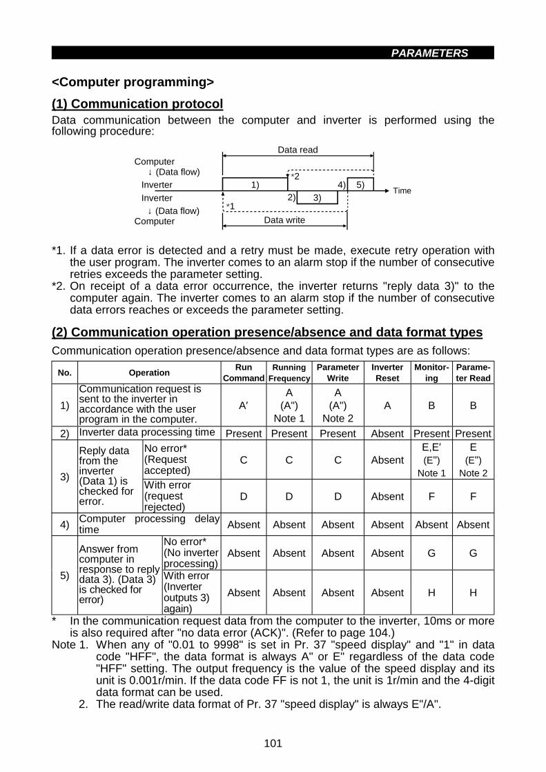
PARAMETERS
101
<Computer programming>
(1) Communication protocolData communication between the computer and inverter is performed using thefollowing procedure:
Data read
Data write
1) 5)4)
3)2)*1
*2↓ (Data flow)
Inverter
InverterTime
Computer
Computer↓ (Data flow)
*1. If a data error is detected and a retry must be made, execute retry operation withthe user program. The inverter comes to an alarm stop if the number of consecutiveretries exceeds the parameter setting.
*2. On receipt of a data error occurrence, the inverter returns "reply data 3)" to thecomputer again. The inverter comes to an alarm stop if the number of consecutivedata errors reaches or exceeds the parameter setting.
(2) Communication operation presence/absence and data format types
Communication operation presence/absence and data format types are as follows:
No. OperationRun
CommandRunning
FrequencyParameter
WriteInverterReset
Monitor-ing
Parame-ter Read
1)
Communication request issent to the inverter inaccordance with the userprogram in the computer.
A′A
(A")Note 1
A(A")
Note 2A B B
2) Inverter data processing time Present Present Present Absent Present Present
No error*(Requestaccepted)
C C C AbsentE,E′(E")
Note 1
E(E")
Note 23)
Reply datafrom theinverter(Data 1) ischecked forerror.
With error(requestrejected)
D D D Absent F F
4)Computer processing delaytime Absent Absent Absent Absent Absent Absent
No error*(No inverterprocessing)
Absent Absent Absent Absent G G
5)
Answer fromcomputer inresponse to replydata 3). (Data 3)is checked forerror)
With error(Inverteroutputs 3)again)
Absent Absent Absent Absent H H
* In the communication request data from the computer to the inverter, 10ms or moreis also required after "no data error (ACK)". (Refer to page 104.)
Note 1. When any of "0.01 to 9998" is set in Pr. 37 "speed display" and "1" in datacode "HFF", the data format is always A" or E" regardless of the data code"HFF" setting. The output frequency is the value of the speed display and itsunit is 0.001r/min. If the data code FF is not 1, the unit is 1r/min and the 4-digitdata format can be used.
2. The read/write data format of Pr. 37 "speed display" is always E"/A".

PARAMETERS
102
(3) Data formatData used is hexadecimal.Data is automatically transferred in ASCII between the computer and inverter.
1) Data format types(1) Communication request data from computer to inverter
Format A *3ENQ Data *4
1 2 3 4 5 6 7 8 9 10 11 12 13
Format A' Data
1 2 3 4 5 6 7 8 9 10 11
Format A"
1 2 3 4 5 6 7 8 9
[Data write]
[Data read]
Format B
1 2 3 4 5 6 7 8 9
10 11 12 13 14 15
Data
Inverter station number
Instruction code
Inverter station number
Instruction code
Inverter station number
Instruction code
Inverter station number
Instruction code
Sum check
Sum check
Sum check
Sum check
Wai
ting
time
Wai
ting
time * 5
Wai
ting
time
Wai
ting
time * 5
←Number of characters
←Number of characters
←Number of characters
←Number of characters
*3ENQ
*3ENQ
*3ENQ
*4
*4
*4
Note:1. The inverter station numbers may be set between H00 and H1F (stations 0and 31) in hexadecimal.
2. *3 indicates the control code.3. *4 indicates the CR or LF code.
When data is transmitted from the computer to the inverter, codes CR(carriage return) and LF (line feed) are automatically set at the end of a datagroup on some computers. In this case, setting must also be made on theinverter according to the computer.Also, the presence and absence of the CR and LF codes can be selectedusing Pr. 124.
4. At *5, when Pr. 123 "waiting time setting" ≠ 9999, create the communicationrequest data without "waiting time" in the data format.(The number of characters is decremented by 1.)
2) Reply data from inverter to computer during data write
*3NAK
1 2 3 4
*4
5
[No data error detected] [Data error detected]
Inverter station number
Format C Format D Error code
*3ACK
*4
1 2 3 4
Inverter station number
←Number of characters ←Number of characters
4
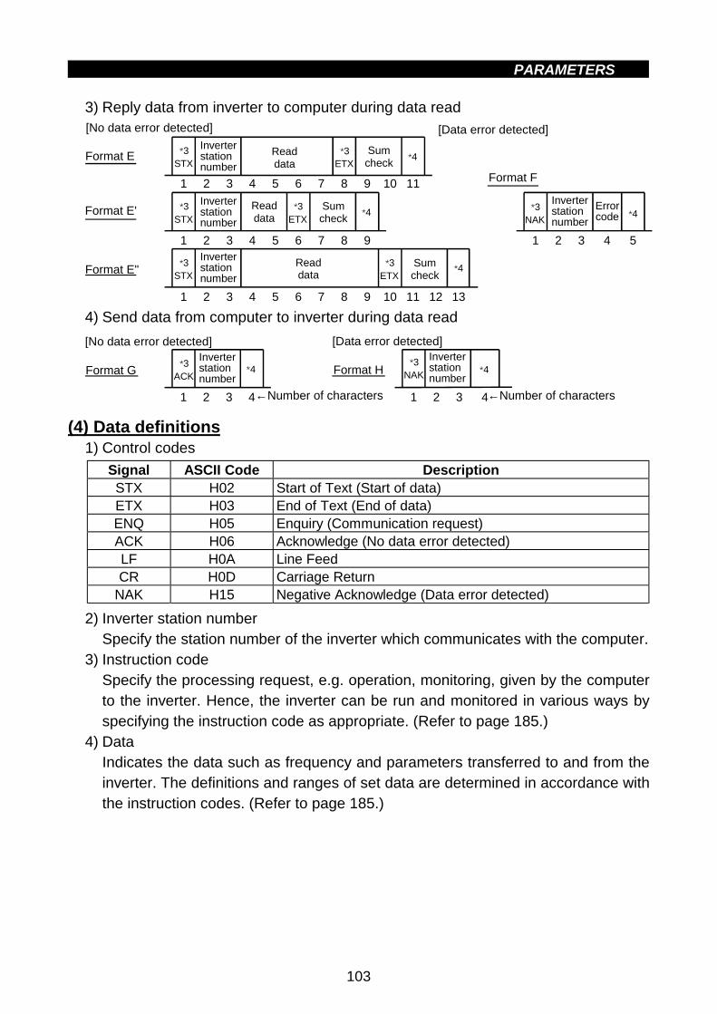
PARAMETERS
103
3) Reply data from inverter to computer during data read
Format F
Format E
*3NAK
1 2 3 4
*4
5
*3STX
*4
1 2 3 4 5 6 7 8 9 10 11
*3ETX
*3STX
*4
1 2 3 4 5 6 7 8 9
*3ETX
*3STX
*4
1 2 3 4 5 6 7 8 9
*3ETX
10 11 12 13
[No data error detected]
Inverter station number
Inverter station number
Readdata
Sum check
Readdata
Sum check
Inverter station number
Readdata
Sum checkFormat E"
Inverter station number
Format E'
[Data error detected]
Errorcode
4) Send data from computer to inverter during data read
Format G
[No data error detected]
*3ACK
*4
1 2 3 4
Inverterstationnumber
←Number of characters
Format H
[Data error detected]
*3NAK
1 2 3 4
*4Inverterstationnumber
←Number of characters
(4) Data definitions1) Control codes
Signal ASCII Code DescriptionSTX H02 Start of Text (Start of data)ETX H03 End of Text (End of data)ENQ H05 Enquiry (Communication request)ACK H06 Acknowledge (No data error detected)LF H0A Line FeedCR H0D Carriage Return
NAK H15 Negative Acknowledge (Data error detected)
2) Inverter station numberSpecify the station number of the inverter which communicates with the computer.
3) Instruction codeSpecify the processing request, e.g. operation, monitoring, given by the computerto the inverter. Hence, the inverter can be run and monitored in various ways byspecifying the instruction code as appropriate. (Refer to page 185.)
4) DataIndicates the data such as frequency and parameters transferred to and from theinverter. The definitions and ranges of set data are determined in accordance withthe instruction codes. (Refer to page 185.)

PARAMETERS
104
5) Waiting timeSpecify the waiting time between the receipt of data at the inverter from thecomputer and the transmission of reply data. Set the waiting time in accordance withthe response time of the computer between 0 and 150ms in 10ms increments(e.g. 1 = 10ms, 2 = 20ms).
Computer↓
Inverter
Inverter↓
Computer
Inverter data processing time= waiting time + data check time
(setting×10ms) (12ms)
Note: If the Pr. 123 "waiting time setting" value is not 9999, create the communicationrequest data with no "waiting time" in the data format. (The number of charactersis decremented by 1.)
6) Response time
(set value 10ms)
(set value 10ms)
Inverter
Computer
(refer to the following calculation expression)
Inverter data processing time = waiting time + data check time(12ms)
10ms or more required
10ms or more required
(refer to the following calculation expression)
STXACK ENQ
(refer to the following calculation expression)
Inverter data processing time = waiting time + data check time(12ms)
10ms or more required
Data sending time (refer to the following calculation expression)
Computer
InverterInverter
Computer
ENQ
Data sending time
Data sending time
Data sending time
Computer
Inverter
[Data sending time calculation expression]
1Communication speed
(bps)
×Number of data
characters(Refer to page 102)
×Communication
specification(Total number of bits)
(See below)
=Data sendingtime (s)
" Communication specificationName Number of Bits
Stop bit length 1 bit2 bits
Data length 7 bits8 bits
Yes 1 bitParity check No 0 bitsIn addition to the bits in the above table, 1 bit is required for the start bit.Minimum total number of bits ... 9 bitsMaximum total number of bits ... 12 bits
4
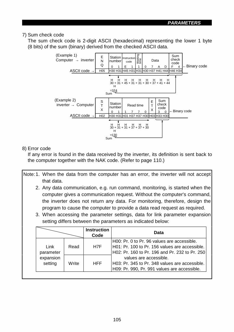
PARAMETERS
105
7) Sum check codeThe sum check code is 2-digit ASCII (hexadecimal) representing the lower 1 byte(8 bits) of the sum (binary) derived from the checked ASCII data.
30 + 31 + 45 + 31 + 31 + 30 + 37 + 41 + 44
=1F4
ENQ 10 1 E 1 0 7 A D F 4
H05 H30 H31 H31H45 H31 H30 H37 H41 H44 H46 H34
STX
0 1 1 7 0 3 0H02 H30 H31 H37H31 H37 H30 H03 H33 H30
ETX
7
(Example 1)Computer → inverter
ASCII code →
(Example 2) inverter → Computer
ASCII code →
Station number
Instructioncode Data
Sum checkcode
H H H H H H H H H
H
H30 + 31 + 31 + 37 + 37 + 30
=130
H H H H H
H
Station number
Sum checkcode
Read time
←Binary code
←Binary code
Wa
itin
g tim
e
Sum
Sum
8) Error codeIf any error is found in the data received by the inverter, its definition is sent back tothe computer together with the NAK code. (Refer to page 110.)
Note:1. When the data from the computer has an error, the inverter will not acceptthat data.
2. Any data communication, e.g. run command, monitoring, is started when thecomputer gives a communication request. Without the computer's command,the inverter does not return any data. For monitoring, therefore, design theprogram to cause the computer to provide a data read request as required.
3. When accessing the parameter settings, data for link parameter expansionsetting differs between the parameters as indicated below:
InstructionCode
Data
Read H7FLinkparameterexpansion
setting Write HFF
H00: Pr. 0 to Pr. 96 values are accessible.H01: Pr. 100 to Pr. 156 values are accessible.H02: Pr. 160 to Pr. 196 and Pr. 232 to Pr. 250
values are accessible.H03: Pr. 345 to Pr. 348 values are accessible.H09: Pr. 990, Pr. 991 values are accessible.

PARAMETERS
106
CAUTION
When the inverter's permissible communication time interval is not set,interlocks are provided to disable operation to prevent hazardousconditions. Always set the communication check time interval beforestarting operation.Data communication is not started automatically but is made only oncewhen the computer provides a communication request. If communicationis disabled during operation due to signal cable breakage etc, the invertercannot be stopped. When the communication check time interval haselapsed, the inverter will come to an alarm stop (E.PUE).The inverter can be coasted to a stop by switching on its RES signal orby switching power off.If communication is broken due to signal cable breakage, computer faultetc, the inverter does not detect such a fault. This should be fully noted.
4

PARAMETERS
107
<Setting items and set data>After completion of parameter settings, set the instruction codes and data then startcommunication from the computer to allow various types of operation control andmonitoring.
No. ItemInstruction
CodeDescription
Numberof DataDigits(DatacodeFF=1)
Read H7BH0001: DeviceNet operationH0002: Communication operation
1Operationmode
Write HFBH0001: DeviceNet operationH0002: Communication operation
4 digits
Output frequency[speed]
H6F
H0000 to HFFFF:Output frequency(hexadecimal) in 0.01Hzincrements[Speed (hexadecimal) inr/min increments if Pr. 37 = 1to 9998]
4 digits(6 digits)
Output current H70H0000 to HFFFF: Output current
(hexadecimal) in 0.01Aincrements
4 digits
Output voltage H71H0000 to HFFFF: Output voltage
(hexadecimal) in 0.1Vincrements
4 digits
H0000 to HFFFF: Two most recent alarmdefinitionsAlarm definition displayexample (instruction codeH74)
b15 b8b7 b0
0 0 1 1 0 0 0 0 0 0 0 0 00 1 1
Previous alarm(H30)
Most recent alarm(HA0)
Alarm dataData Description Data DescriptionH00 No alarm H60 OLTH10 OC1 H70 BEH11 OC2 H80 GFH12 OC3 H81 LFH20 OV1 H90 OHTH21 OV2 HA0 OPTH22 OV3 HB0 PEH30 THT HB1 PUEH31 THM HB2 RETH40 FIN
2
Mon
itorin
g
Alarm definitionH74 toH77
4 digits
3 Run command HFA
b70 0 0 0 0 0 01
b0 b0 : b1 : Forward rotation (STF)b2 : Reverse rotation (STR)b3 : b4 : b5 : b6 : b7 :
[Example 1] H02 ... Forward rotation[Example 2] H00 ... Stop
[For example 1]2 digits

PARAMETERS
108
No. ItemInstruction
CodeDescription
Numberof DataDigits(DatacodeFF=1)
4Inverter statusmonitor
H7A
b70 0 0 0 0 0 01
b0
(For example 1)
[Example 1] H02 ... During forward rotation[Example 2] H80 ... Stop due to alarm
b0: Inverter running (RUN)b1: Forward rotationb2: Reverse rotation b3: Up to frequency (SU)b4: Overload (OL)b5: b6: Frequency detection (FU)b7: Alarm occurrence
2 digits
Set frequency read(E2PROM)
H6E
Set frequency read(RAM) H6D
Reads the set frequency (RAM or E2PROM).H0000 to H9C40: 0.01Hz increments(hexadecimal)
4 digits(6 digits)
Set frequency write(E2PROM)
HEE5
Set frequency write(RAM)
HED
H0000 to H9C40: 0.01Hz increments(hexadecimal)(0 to 400.00Hz)To change the set frequency consecutively,write data to the inverter RAM.(Instruction code: HED)
4 digits(6 digits)
6 Inverter reset HFD
H9696: Resets the inverter.As the inverter is reset on start of communica-tion by the computer, the inverter cannot sendreply data back to the computer.
4 digits
7Alarm definitionbatch clear
HF4 H9696: Batch clear of alarm history 4 digits
All parameters return to the factory settings.Any of two different all clear operations isperformed according to the data.
Pr.
Data
Communi-
cation Pr.Other Pr.* HFF
H9696 ' ' 'H9966 ' ' '
When all parameter clear is executed forH9696 or H9966, communication-relatedparameter settings also return to the factorysettings. When resuming operation, set theparameters again.
8 All parameter clear HFC
* Pr. 75 is not cleared.
4 digits
9 Parameter writeH80 toHFD
10 Parameter readH00 toH7B
Refer to the "Data Code List" (page 185) andwrite and/or read the values as required.
4 digits
4

PARAMETERS
109
No. ItemInstruction
CodeDescription
Numberof DataDigits(DatacodeFF=1)
Read H7F
11
Linkparameterexpansionsetting
Write HFF
H00 to H6C and H80 to HEC parameter valuesare changed.H00: Pr. 0 to Pr. 96 values are accessible.H01: Pr. 117 to Pr. 156 values are accessible.H02: Pr. 160 to Pr. 192 and Pr. 232 to Pr. 250
values are accessible.H03: Pr. 345 to Pr. 348 values are accessible.H09: Pr. 990, Pr. 991 values are accessible.
2 digits
REMARKSFor the instruction codes HFF, their set values are held once they are written, butchanged to 0 when the inverter is reset or all clear is performed.

PARAMETERS
110
<Error Code List>
The corresponding error code in the following list is displayed if an error is detected inany communication request data from the computer:
ErrorCode
Item Definition Inverter Operation
H0Computer NAKerror
The number of errors consecutivelydetected in communication request datafrom the computer is greater than allowednumber of retries.
H1 Parity errorThe parity check result does not match thespecified parity.
H2 Sum check errorThe sum check code in the computer doesnot match that of the data received by theinverter.
H3 Protocol error
Data received by the inverter is in wrongprotocol, data receive is not completedwithin given time, or CR and LF are not asset in the parameter.
H4 Framing errorThe stop bit length is not as specified byinitialization.
H5 Overrun errorNew data has been sent by the computerbefore the inverter completes receiving thepreceding data.
Brought to an alarmstop (E.PUE) if erroroccurs continuouslymore thanthe allowablenumber of retries.
H6
H7 Character errorThe character received is invalid (otherthan 0 to 9, A to F, control code).
Does not acceptreceived data but isnot brought to alarmstop.
H8 H9
HA Mode errorParameter write was attempted in otherthan the computer link operation mode orduring inverter operation.
HBInstruction codeerror
The specified command does not exist.
HC Data range errorInvalid data has been specified forparameter write, frequency setting, etc.
Does not acceptreceived data but isnot brought to alarmstop.
HD HE HF
4

PARAMETERS
111
(5) Communication specifications for RS-485 communication
Operation ModeOperationLocation
ItemCommunication
Operation from PUConnector
Run command (start) EnableRunning frequency setting EnableMonitoring EnableParameter write Enable (*2)Parameter read EnableInverter reset Enable
Computer userprogram viaPU connector
Stop command (*1) EnableInverter reset EnableRun command Disable
Control circuitterminal
Running frequency setting Disable
*1 As set in Pr. 75.*2 As set in Pr. 77.
Note: At occurrence of RS-485 communication fault, the inverter cannot be resetfrom the computer.
(6) Operation at alarm occurrence
Operation Mode
Fault Location DescriptionCommunication
Operation(PU connector)
Inverter operation StopInverter fault
Communication PU connector ContinuedInverter operation Stop/continued (*3)Communication
error(Communicationfrom PUconnector)
Communication PU connector Stop
*3: Can be selected using the corresponding parameter (factory-set to stop).
(7) Communication error
Fault Location Error Message RemarksCommunication error(Communication from PU connector)
Not displayed Error code is E.PUE

PARAMETERS
112
" " PID control (Pr. 128 to Pr. 134)4.2.30 Settings for connection of FR-PU04 (Pr. 145, Pr. 990, Pr. 991)
Pr. 145 "Parameter unit display language selection"
Pr. 990 "Buzzer beep control"
Pr. 991 "LCD contrast"
!!!! All of the below parameters are only applicable when using the FR-PU04 parameter
unit.
By setting the Pr. 145 "Parameter unit display language selection" value, you canselect the language displayed on the parameter unit.
Pr. 145 Setting Display Language0 Japanese (factory setting)1 English2 German3 French4 Spanish5 Italian6 Swedish7 Finnish
By setting the Pr. 990 "Buzzer beep control" value, you can select whether the "beep"is sounded or not when you press any of the parameter unit key.
Pr. 990 Setting Description0 No sound1 Sound generated (factory setting)
By setting the Pr. 991 "LCD contrast" value, you can adjust the contrast of theparameter unit LCD.
Pr. 991 Setting
0 to 63
[0] [63][53]
Bright DarkFactory setting
Note: The LCD contrast setting will not be stored until the WRITE key is pressed.
4

PARAMETERS
113
Pr. 192"A, B, C terminal (ABC) function selection"
Related parameters
" Output current detection function (Pr. 150 to Pr. 151)4.2.31 Output current detection function (Pr. 150, Pr. 151)
Pr. 150 "output current detection level"
Pr. 151 "output current detection period"
! If the output current remains higher than the Pr. 150 setting during inverter operationfor longer than the time set in Pr. 151, the output current detection signal (Y12) isoutput.(Use Pr. 192 to assign the terminal used for Y12 signal output.)
ParameterNumber
FactorySetting
SettingRange
150 150% 0 to 200.0%151 0 0 to 10 s
Time
OFF ON OFF
100ms
Pr.151
Pr.150
Outp
ut cu
rrent
Output current detection signal (Y12)
<Setting>
Refer to the following list and set the parameters:
ParameterNumber Description
150Set the output current detection level.100% is the rated inverter current.
151Set the output current detection time. Set a period of time from when theoutput current rises to or above the Pr. 150 setting to when the outputcurrent detection signal (Y12) is output.
Note:1. The output current detection signal is held on for about 100ms (at least) if itswitches on once when the output current rises to or above the presetdetection level.
2. This function is also valid during execution of offline auto tuning.3. When the terminal functions are changed using Pr. 192, the other functions
may be affected. Confirm the functions of the corresponding terminals beforemaking settings.
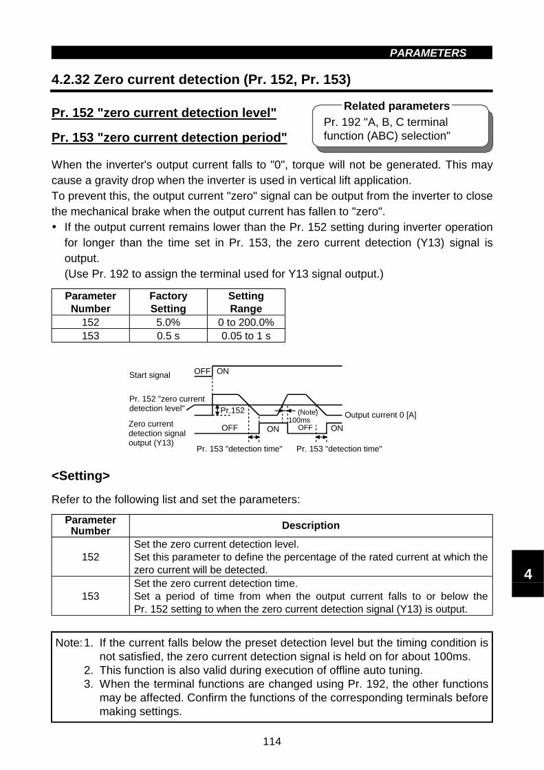
PARAMETERS
114
Pr. 192 "A, B, C terminalfunction (ABC) selection"
Related parameters
" " Zero current detection (Pr. 152, Pr. 153)4.2.32 Zero current detection (Pr. 152, Pr. 153)
Pr. 152 "zero current detection level"
Pr. 153 "zero current detection period"
When the inverter's output current falls to "0", torque will not be generated. This maycause a gravity drop when the inverter is used in vertical lift application.To prevent this, the output current "zero" signal can be output from the inverter to closethe mechanical brake when the output current has fallen to "zero".! If the output current remains lower than the Pr. 152 setting during inverter operation
for longer than the time set in Pr. 153, the zero current detection (Y13) signal isoutput.(Use Pr. 192 to assign the terminal used for Y13 signal output.)
ParameterNumber
FactorySetting
SettingRange
152 5.0% 0 to 200.0%153 0.5 s 0.05 to 1 s
OFF ONStart signal
Pr. 152 "zero current detection level"
OFF ONZero current detection signal output (Y13)
Pr.152
OFF ON
(Note) Output current 0 [A]100ms
Pr. 153 "detection time"Pr. 153 "detection time"
<Setting>
Refer to the following list and set the parameters:
ParameterNumber Description
152Set the zero current detection level.Set this parameter to define the percentage of the rated current at which thezero current will be detected.
153Set the zero current detection time.Set a period of time from when the output current falls to or below thePr. 152 setting to when the zero current detection signal (Y13) is output.
Note:1. If the current falls below the preset detection level but the timing condition isnot satisfied, the zero current detection signal is held on for about 100ms.
2. This function is also valid during execution of offline auto tuning.3. When the terminal functions are changed using Pr. 192, the other functions
may be affected. Confirm the functions of the corresponding terminals beforemaking settings.
4

PARAMETERS
115
CAUTION
The zero current detection level setting should not be too high, and thezero current detection time setting should not be too long. Otherwise, thedetection signal may not be output when torque is not generated at a lowoutput current.To prevent the machine and equipment from resulting in hazardousconditions by use of the zero current detection signal, install a safetybackup such as an emergency brake.
" Stall prevention operation selection (Pr. 156)4.2.33 Stall prevention function and current limit function (Pr. 156)
Pr. 156 " stall prevention operationselection"
You can make settings to disable stall prevention caused by overcurrent and to disablethe inverter from an overcurrent trip if an excessive current occurs due to sudden loadvariation or turning the inverter's output side ON-OFF (to disable the fast-responsecurrent limit which limits the current).
ParameterNumber
FactorySetting
SettingRange
156 0 0 to 31, 100
Pr. 22 "stall prevention operation level"Pr. 23 "stall prevention operation level
compensation factor at doublespeed"
Related parameters

PARAMETERS
116
<Setting>Refer to the following tables and set the parameter as required.
Stall PreventionOperationSelection ': Activated ": Not activated
Stall PreventionOperationSelection ': Activated ": Not activatedPr. 156
Setting
Fast-ResponseCurrentLimit': Activated": Notactivated
Ac
ce
lera
tio
n
Co
ns
tan
ts
pe
ed
De
ce
lera
tio
n
OL SignalOutput':Operationcontinued":Operationnotcontinued(Note 1)
Pr. 156Setting
Fast-ResponseCurrentLimit': Activated": Notactivated
Ac
ce
lera
tio
n
Co
ns
tan
ts
pe
ed
De
ce
lera
tio
n
OL SignalOutput':Operationcontinued":Operationnotcontinued(Note 1)
0 ' ' ' ' ' 16 ' ' ' ' "1 " ' ' ' ' 17 " ' ' ' "2 ' " ' ' ' 18 ' " ' ' "3 " " ' ' ' 19 " " ' ' "4 ' ' " ' ' 20 ' ' " ' "5 " ' " ' ' 21 " ' " ' "6 ' " " ' ' 22 ' " " ' "7 " " " ' ' 23 " " " ' "8 ' ' ' " ' 24 ' ' ' " "9 " ' ' " ' 25 " ' ' " "
10 ' " ' " ' 26 ' " ' " "11 " " ' " ' 27 " " ' " "12 ' ' " " ' 28 ' ' " " "13 " ' " " ' 29 " ' " " "14 ' " " " ' 30 ' " " " "15 " " " " ' 31 " " " " "
Dri
vin
g
' ' ' ' '
100
Re
ge
ne
rativ
e
" " " " '
Note 1: When "Operation not continued for OL signal output" is selected, the "E.OLT"alarm code (stopped by stall prevention) is displayed and operation stopped.
2: If the load is heavy, the lift is predetermined, or the acceleration/decelerationtime is short, the stall prevention may be activated and the motor notstopped in the preset acceleration/deceleration time. Therefore, set optimumvalues to the Pr. 156 and stall prevention operation level.
CAUTION
Always perform test operation.Stall prevention operation performed during acceleration may increasethe acceleration time.Stall prevention operation performed during constant speed may causesudden speed changes.Stall prevention operation performed during deceleration may increasethe deceleration time, increasing the deceleration distance.
4

PARAMETERS
117
" User group selection (Pr. 160, Pr. 173 to Pr. 176)4.2.34 User group selection (Pr. 160, Pr. 173 to Pr. 176)
Pr. 160 "user group read selection"
Pr. 173 "user group 1 registration"
Pr. 174 "user group 1 deletion"
Pr. 175 "user group 2 registration"
Pr. 176 "user group 2 deletion"Among all parameters, a total of 32 parameters can be registered to two different usergroups. The registered parameters may only be accessed.The other parameters cannot be read.
ParameterNumber
FactorySetting Setting Range Remarks
160 0 0, 1, 10, 11173 0 0 to 999174 0 0 to 999, 9999 9999: Batch deletion175 0 0 to 999176 0 0 to 999, 9999 9999: Batch deletion
<Examples of use>
(1) Registration of parameter to user group
Write the parameter numbers to be registered to Pr. 173 (User group 1 registration) orPr. 175 (User group 2 registration). Write the parameter numbers one by one.
(2) Deletion of parameter from the user group
Write the parameter numbers to be deleted to Pr. 174 (User group 1 deletion) orPr. 176 (User group 2 deletion). Write the parameter numbers one by one.
(3) Set the required value in Pr. 160 to make the user group or groups valid or invalid.
Pr. 160 Setting Description0 Previous parameters read1 User group 1's parameters read
10 User group 2's parameters read11 User group 1 and 2 parameters read
Note:1. The Pr. 77, Pr. 160 and Pr. 991 values may always be read independently ofthe user group setting.
2. The Pr. 173 or Pr. 174 value read indicates the number of parametersregistered to group 1, and the Pr. 175 or Pr. 176 value read indicates thenumber of parameters registered to group 2.
3. If "0" is set in the second digit of two-digit Pr. 160, it is not displayed.However, "0" is displayed when it is set in the first digit only.
4. When "9999" is set in Pr. 174 or Pr. 176, the parameters registered to thecorresponding user group are batch-deleted.

PARAMETERS
118
Pr. 52 "PU main display dataselection"
Related parameter
4.2.35 Actual operation hour meter clear (Pr. 171)
Pr. 171 "actual operation hour meterclear"
You can clear the monitor (actual operation hour) value which is selected when Pr. 52is "23".
ParameterNumber
FactorySetting
SettingRange
171 0 0
<Setting>
Write "0" in the parameter to clear the actual operation hour.
Pr. 173 to Pr. 176 &&&& Refer to Pr. 160.
4.2.36 Input terminal (DeviceNet input) function selection (Pr. 180to Pr. 183)
" Input terminal function selection (Pr. 180 to Pr. 183)
Pr. 180 "(RL) function selection"
Pr. 181 "(RM) function selection"
Pr. 182 "(RH) function selection"
Pr. 183 "MRS terminal (MRS) function selection"
Use these parameters to select/change the input terminal (DeviceNet input) functions.
ParameterNumber
Terminal(DeviceNet
input) Symbol
FactorySetting
Factory-Set TerminalFunction
SettingRange
Remarks
180 (RL) 0Low-speed operationcommand (RL)
0 to 3, 6,8, 18
181 (RM) 1Middle-speed operationcommand (RM)
0 to 3, 6,8, 18
182 (RH) 2High-speed operationcommand (RH)
0 to 3, 6,8, 18
DeviceNetinput
183 MRS (MRS) 6 Output shut-off (MRS)0 to 3,
6 to 8, 18
DeviceNetinput, inputterminal
4

PARAMETERS
119
" " Actual operation hour meter clear (Pr. 171)
<Setting>
Refer to the following list and set the parameters.
Setting SignalName Function Related
Parameters
0 RL Low-speed operation commandPr. 4 to Pr. 6Pr. 24 to Pr. 27Pr. 232 to Pr. 239
1 RM Middle-speed operation commandPr. 4 to Pr. 6,Pr. 24 to Pr. 27,Pr. 232 to Pr. 239
2 RH High-speed operation commandPr. 4 to Pr. 6,Pr. 24 to Pr. 27,Pr. 232 to Pr. 239
3 RT Second function selection Pr. 44 to Pr. 486 MRS Output shut-off terminal
7 OH
External thermal relay input *The external thermal relay provided for overheatprotection or the embedded temperature relaywithin the motor is activated to stop the inverter.
Only Pr.183 may beset. (Input terminal)
8 REX 15-speed selection (combination with threespeeds of RL, RM, RH)
Pr. 4 to Pr. 6,Pr. 24 to Pr. 27,Pr. 232 to Pr. 239
18 X18General-purpose magnetic flux vector-V/F switch-over (OFF: general-purpose magnetic flux vectorcontrol, ON: V/F control) (Note 3)
Pr. 80
*: Activated when the relay contact "opens".
Note:1. One function can be assigned to two or more terminals (DeviceNet input). Inthis case, the terminal (DeviceNet input) inputs are OR’ ed.
2. The speed command priorities are higher in order of multi-speed setting(RH, RM, RL, REX).
3. When V/F control is selected using the V/F-general-purpose magnetic fluxswitch-over function, the secondry functions are also selected.During operation, you cannot switch between V/F and general-purposemagnetic flux. Should you switch between V/F and general-purposemagnetic flux, only the second functions are selected.
4. Functions are invalid if values other than the above are set to Pr. 180 toPr. 183 (input terminal (DeviceNet input) function selection).

PARAMETERS
120
" Output terminal function selection (Pr. 190 to Pr. 192)4.2.37 Output terminal (DeviceNet input) function selection (Pr. 190
to Pr. 192)
Pr. 190 "(RUN) function selection"Pr. 191 "(FU) function selection"Pr. 192 "A, B, C terminal (ABC) function selection"You can change the functions of the contact output terminals (DeviceNet input).Inverter status is not returned. Refer to page 53 for details.
ParameterNumber
Terminal(DeviceNet
input) Symbol
FactorySetting
Factory-Set TerminalFunction
SettingRange Remarks
190 (RUN) 0 Inverter running 0 to 99
191 (FU) 4 Output frequencydetection 0 to 99
DeviceNetoutput
192 A, B, C (ABC) 99 Alarm output 0 to 99
DeviceNetoutput,contactoutputterminal
<Setting>Refer to the following table and set the parameters:
Setting SignalName Function Operation Related
Parameters
DeviceNetoutput
(Inverterstatus)
0 RUN Inverter running
Output during operation whenthe inverter output frequencyrises to or above the startingfrequency.
0 Bit
1 SU Up to frequency Refer to Pr. 41 "up-to-frequencysensitivity". (Note 1) Pr. 41 3 Bit
3 OL Overload alarm Output while stall preventionfunction is activated.
Pr. 22,Pr. 23,Pr. 66
4 Bit
4 FUOutputfrequencydetection
Refer to Pr. 42, Pr. 43 (outputfrequency detection).
Pr. 42,Pr. 43 6 Bit
11 RY Inverteroperation ready
Output when the inverter isready to be started by switchingthe start signal on.
12 Y12 Output currentdetection
Refer to Pr. 150 and Pr. 151(output current detection).
Pr. 150,Pr. 151
13 Y13 Zero currentdetection
Refer to Pr. 152 and Pr. 153(zero current detection).
Pr. 152,Pr. 153
98 LF Minor faultoutput
Output when a minor fault (fanfailure or communication errorwarning) occurs.
Pr. 121,Pr. 244
99 ABC Alarm outputOutput when the inverter'sprotective function is activatedto stop the output (major fault).
7 Bit
Use the contact output terminals for the shaded signals.
Note:1. The same function may be set to more than one terminal (DeviceNet output).2. Pr. 190 to Pr. 192 do not function if the values set are other than the above.
4

PARAMETERS
121
Pr. 232 to Pr. 239&&&& Refer to Pr. 4.
Pr. 240&&&& Refer to Pr. 72.
" Cooling fan operation selection (" Pr. 244)4.2.38 Cooling fan operation selection (Pr. 244)
Pr. 244 "cooling fan operation selection"
You can control the operation of the cooling fan built in the inverter (whether there is acooling fan or not depends on the models. Refer to the outline dimensional drawings(page 152)).
ParameterNumber
FactorySetting
SettingRange
244 0 0, 1
<Setting>
Setting Description
0Operated at power on (independent of whether the inverter is running or ata stop).
1
Cooling fan on-off control valid(The cooling fan is always on while the inverter is running. During a stop,the inverter status is monitored and the fan switches on-off according totemperature.)
<Reference>
In either of the following cases, fan operation is regarded as faulty and the light fault(LF) signal is output. Use Pr. 192 "A, B, C terminal (ABC) function selection" to allocatethe terminal used to output the LF signal.1) Pr. 244 = "0"
When the fan comes to a stop with power on.2) Pr. 244 = "1"
When the inverter is running and the fan stops during fan ON command or the fanstarts during fan OFF command.
Note: When the terminal assignment is changed using Pr. 192, the other functionsmay be affected. Confirm the functions of the corresponding terminals beforemaking settings.

PARAMETERS
122
" " Slip compensation (Pr. 245 to Pr. 247)4.2.39 Slip compensation (Pr. 245 to Pr. 247)
Pr. 245 "rated motor slip"
Pr. 246 "slip compensation response time constant"
Pr. 247 "constant-output region slip compensation selection"
The inverter output current may be used to assume motor slip to keep the motor speedconstant.
ParameterNumber
FactorySetting
Setting Range Remarks
245 9999 0 to 50%, 9999 9999: No slip compensation246 0.5 0.01 to 10 s247 9999 0, 9999 9999: Slip compensation made
<Setting>
Synchronous speed at base frequency - rated speedRated slip =
Synchronous speed at base frequency ×100[%]
ParameterNumber
Setting Function
0 to 50% Used to set the rated motor slip.245
9999 Slip compensation is not made.246 0.01 to 10 s Used to set the slip compensation response time. (Note)
0Slip compensation is not made in the constant outputrange (frequency range above the frequency set in Pr. 3).247
9999 Slip compensation is made in the constant output range.
Note: When this value is made smaller, response will be faster.However, as load inertia is greater, a regenerative overvoltage (OVT) error ismore liable to occur.
4

PARAMETERS
123
Pr. 7 "acceleration time"Pr. 8 "deceleration time"Pr. 44 "second acceleration/
deceleration time"Pr. 45 "second deceleration
time"
Related parameters
" " Ground fault detection at start (Pr. 249)4.2.40 Ground fault detection at start (Pr. 249)
Pr. 249 "ground fault detection at start"
You can select whether ground fault detection at start is made or not. Ground faultdetection is made only immediately after the start signal is input to the inverter.If a ground fault occurs during operation, the protective function is not activated.
ParameterNumber
FactorySetting
Setting Range
249 0 0, 1
<Setting>
Setting Description0 Ground fault detection not made1 Ground fault detection made
Note:1. Since detection is made at a start, an about 20ms output delay occurs atevery start.
2. When a ground fault is detected with "1" set in Pr. 249, alarm output "E.GF"is detected and the output is shut off.
3. If the motor capacity is less than 0.1kW, ground fault protection may not beprovided.
" Stop selection (Pr. 250)4.2.41 Stop selection (Pr. 250)
Pr. 250 "stop selection"
Used to select the stopping method (deceleration to a stop or coasting) when theDeviceNet control input command (STF/STR) switches off.
ParameterNumber
FactorySetting
Setting Range
250 99990 to 100 s, 1000 to1100 s, 8888, 9999

PARAMETERS
124
(1)Pr. 250 = "9999"When the start signal switches off, the motor is decelerated to a stop.
Time
Outputfrequency (Hz)
ON OFFStart signal
Decelerated when start signal switches off.
Deceleration time (time set in Pr. 8, etc.)
DC brake
(2)Pr. 250 = 0 to 100 seconds (output is shut off after preset time)The output is shut off when the time set in Pr. 250 has elapsed after the start signalwas switched off. The motor coasts to a stop.
OFFStart signal
Output is shut off when time set in Pr. 250 has elapsed after start signal was switched off.Output
frequency (Hz)
Motor coasts to a stop.
Time
OFFRUN signal
When the Pr. 250 value is 8888, the functions of terminals STF and STR change asshown below:STF = start signal, STR = rotation direction signal
STF STR Inverter Operating StatusOFF OFFOFF ON
Stop
ON OFF Forward rotationON ON Reverse rotation
When the Pr. 250 value is any of 1000 to 1100s, the functions of terminals STF andSTR are the same as when the Pr. 250 value is 8888.Also, for the stopping method used when the start signal switches off, the output is shutoff (the motor coasts to a stop) after the period set in Pr. 250 (i.e. 1000s) have elapsed.
Note:1. The RUN signal switches off when the output stops.2. When the start signal is switched on again during motor coasting, the motor
starts at 0Hz.3. When the Pr. 250 value is 0, the output is shut off within the shortest time.
4

PARAMETERS
125
4.2.42 DeviceNet specific parameters (Pr. 345 to Pr. 348)
Pr. 345 "DeviceNet Address Startup Data (Lower byte)"
Pr. 346 "DeviceNet Baudrate Startup Data (Lower byte)"
Pr. 347 "DeviceNet Address Startup (Higher byte)"
Pr. 348 "DeviceNet Baudrate Startup Data (Higher byte)"
Pr. 345 to Pr. 348 are specific DeviceNet parameters. They are described below.
Pr. No. FunctionSettingRange
MinimumIncrement
DefaultSetting
345DeviceNet AddressStartup Data (Lower byte)
0 to 255 1 63 (0x3F)
346DeviceNet BaudrateStartup Data (Lower byte)
0 to 255 1 132 (0x84)
347DeviceNet AddressStartup Data (Higher byte)
0 to 255 1 160 (0xA0)
348DeviceNet BaudrateStartup Data (Higher byte)
0 to 255 1 80 (0x50)
The PU displays only in decimal integers. The hexadecimal integers in the parenthesesare used here for easy bitmap reference only.
Pr. 345 and Pr. 347 are bit-mapped parameters and are defined as follows.
14 1315 12 11 10 9 8 7 6 5 4 3 2 1 0
Bit7 6 5 4 3 2 1 Bit0 Bit7 6 5 4 3 2 1 Bit0
WDA
Pr.347 Pr.345
Address key DN fault mode Device node address
Pr. 346 and Pr. 348 are bit-mapped parameters and are defined as follows.
15 14 13 12 11 10 9 8 7 6 5 4 3 2 1 0
Bit7 6 5 4 3 2 1 Bit0 Bit7 6 5 4 3 2 1 Bit0
Pr.348 Pr.346
Baud rate key Input assembly Output assembly Baud rate

PARAMETERS
126
Definitions of each registration
Name Description DefinitionDefaultsetting
Watch dogtimeout operation(WDA) (Note)
DeviceNet connection object(Class code 0x05)Instance 2 attribute 12
0 = Transition to timeout1 = Automatic delete2 = Automatic reset
0
DN fault mode
Supports the controlmanagement object. (Classcode 0x29) Instance attribute16, DN fault mode
0 = Fault and stop1 = Ignore
0
Input assembly
Value of assembly ID used inconnection object. (Class code0x05) Instance attribute 16,consumed_connection_path
Assembly ID0 = 701 = 716 = 1768 = 150
1
Output assembly
Assembly ID value used inconnection object. (Class code0x05) Instance attribute 14,produced_connection_path
Assembly instance ID0 = 201 = 216 = 1268 = 100
1
Baud rateDeviceNet object value (Classcode 0x03) Instance attribute 2,baud rate
0 = 125 kbps1 = 250 kbps2 = 500 kbps
0
Device addressDeviceNet object value (Class0x03) Instance attribute 1, MACID
Node address; Range is 0 to 63(same definition as attribute)
63
Address key Internal confirmation 1010-setting value; No others 1010Baud rate key Internal confirmation 1010-setting value; No others 0101
Note: The parameter setting will be changed back to the factory setting (0) whenreconnected after a disconnection.
Normally, these parameters are not accessed via the PU. Instead, a DeviceNet userwill access the various fields of these parameters via DeviceNet and set themaccording to the table above.
Pr. 990 to Pr. 991&&&& Refer to Pr. 145.
4

C H A P T E R 5PROTECTIVEFUNCTIONS
This chapter explains the "protective functions" of this
product.
Always read the instructions before using the equipment.
5.1 Errors (Alarms) ....................................................... 127
5.2 Troubleshooting ...................................................... 135
5.3 Precautions for Maintenance and Inspection .......... 140
CHAPTER 5PROTECTIVE FUNCTIONS
Chapter 1
Chapter 2
Chapter 3
Chapter 4
Chapter 5
Chapter 6

5.1 Errors (Alarms)PROTECTIVE FUNCTIONS
127
5 PROTECTIVE FUNCTIONS5.1 Errors (Alarms)
If any fault has occurred in the inverter, the corresponding protective function isactivated to bring the inverter to an alarm stop and automatically give thecorresponding error (alarm) indication on the PU display.If your fault does not correspond to any of the following errors or if you have any otherproblem, please contact your sales representative.
• Retention of alarm output signal .... When the magnetic contactor (MC) provided onthe power supply side of the inverter is opened atthe activation of the protective function, theinverter's control power will be lost and the alarmoutput will not be held.
• Alarm indication ............................. When the protective function is activated, theoperation panel display automatically switches tothe above indication.
• Resetting method .......................... When the protective function is activated, theinverter output is kept stopped. Unless reset,therefore, the inverter cannot restart. Switchpower off once, then on again; power off once,then on again; or apply RES signal for more than0.1 seconds.
• When the protective function is activated, take the corresponding corrective action,then reset the inverter, and resume operation.
5.1.1 Operation at alarm occurrence
Operation ModeFault
DeviceNet™ operation PU operationInverter fault Continued ContinuedCommunication error Inverter trip Stop
(1) Inverter alarm
Refer to page page 135 and remove the cause of the alarm.
(2) Communication alarm
Check the states of the operating status indicator LED and remove the cause of thealarm. Check the DeviceNet™ master station. (Refer to page 138)
If any fault has occurred in the inverter, the protective function is activated, the invertercomes to an alarm stop, and the ALARM lamp is lit. When the parameter unit(FR-PU04) is used, the PU display automatically gives any of the following error(alarm) indications.When the protective function is activated, reset the inverter.

PROTECTIVE FUNCTIONS
128
5.1.2 Error (alarm) definitions
(1) Major faultsWhen the protective function is activated, the inverter output is shut off and the alarm isoutput.FR-PU04 Indication OC During Acc
Name Overcurrent shut-off during acceleration
DescriptionWhen the inverter output current reaches or exceeds approximately200% of the rated current during acceleration, the protective circuit isactivated to stop the inverter output.
Check pointCheck for sudden acceleration.Check for output short-circuit/ground fault.
Corrective action Increase the acceleration time.
FR-PU04 Indication Stedy Spd OC
Name Overcurrent shut-off during constant speed
DescriptionWhen the inverter output current reaches or exceeds approximately200% of the rated current during constant speed, the protectivecircuit is activated to stop the inverter output.
Check pointCheck for sudden load change.Check for output short-circuit/ground fault.
Corrective action Keep load stable.
FR-PU04 Indication OC During Dec
Name Overcurrent shut-off during deceleration
Description
When the inverter output current reaches or exceeds approximately200% of the rated current during deceleration (other thanacceleration or constant speed), the protective circuit is activated tostop the inverter output.
Check pointCheck for sudden speed reduction.Check for output short-circuit/ground fault.Check for too fast operation of motor's mechanical brake.
Corrective actionIncrease the deceleration time.Adjust brake operation.
FR-PU04 Indication OV During Acc
Name Regenerative overvoltage shut-off during acceleration
Description
If regenerative energy causes the inverter's internal main circuit DCvoltage to reach or exceed the specified value, the protective circuitis activated to stop the inverter output. It may also be activated by asurge voltage generated in the power supply system.
Check point Check for too slow acceleration.
Corrective action Decrease the acceleration time.5

PROTECTIVE FUNCTIONS
129
FR-PU04 Indication Stedy Spd OVName Regenerative overvoltage shut-off during constant speed
Description
If regenerative energy causes the inverter's internal main circuit DCvoltage to reach or exceed the specified value, the protective circuitis activated to stop the inverter output.It may also be activated by a surge voltage generated in the powersupply system.
Check point Check for sudden load change.
Corrective action• Keep load stable.• Use the brake unit or high power factor converter (FR-HC) as
required.
FR-PU04 Indication OV During DecName Regenerative overvoltage shut-off during deceleration or stop
Description
If regenerative energy causes the inverter's internal main circuit DCvoltage to reach or exceed the specified value, the protective circuitis activated to stop the inverter output.It may also be activated by a surge voltage generated in the powersupply system.
Check point Check for sudden speed reduction.
Corrective action
• Increase the deceleration time. (Set the deceleration time whichmatches the inertia moment of the load)
• Decrease the braking duty.• Use the brake unit or high power factor converter (FR-HC) as
required.
FR-PU04 Indication Motor OverloadName Motor overload shut-off (electronic overcurrent protection) (Note 1)
Description
The electronic overcurrent protection in the inverter detects motoroverheat due to overload or reduced cooling capability duringconstant-speed operation to stop the inverter output. When a multi-pole motor or two or more motors are run, provide a thermal relay inthe output side of the inverter.
Check point Check the motor for use under overload.
Corrective action• Reduce the load weight.• For the constant-torque motor, change the Pr. 71 setting to the
constant-torque motor setting.
FR-PU04 Indication Inv. OverloadName Inverter overload shut-off (electronic overcurrent protection) (Note 1)
Description
If a current of more than 150% of the rated output current flows andovercurrent shut-off does not occur (200% or less), inverse-timecharacteristics cause the electronic overcurrent protection to beactivated to stop the inverter output in order to protect the outputtransistors.
Check point Check the motor for use under overload.Corrective action Reduce the load weight.
Note:1 Resetting the inverter initializes the internal heat integrating data of theelectronic overcurrent protection.
PROTECTIVE FUNCTIONS
130
FR-PU04 Indication H/Sink O/Temp
Name Fin overheat
DescriptionIf the cooling fin overheats, the overheat sensor is actuated to stopthe inverter output.
Check point• Check for too high ambient temperature.• Check for cooling fin clogging.
Corrective action Set the ambient temperature to within the specifications.
FR-PU04 Indication Br. Cct. Fault (Note)
Name Brake transistor alarm detection (Note 2)
Description
If a brake transistor fault occurs due to excessively largeregenerative energy from the motor, for example, that fault isdetected to stop the inverter output. In this case, the inverter powermust be switched off immediately.
Check point Check for improper braking duty.
Corrective actionChange the inverter.Please contact your sales representative.
Note:2 This function is activated only when the optional brake resistor is connected.
FR-PU04 Indication Ground Fault
Name Output side ground fault overcurrent protection
Description
This function stops the inverter output if a ground fault overcurrentflows due to a ground fault which occurred in the inverter's output(load) side. Use Pr. 249 "ground fault detection at start" to setwhether the protective function is to be activated or not.
Check point Check for a ground fault in the motor and connection cable.Corrective action Remedy the ground fault portion.
FR-PU04 Indication OH Fault
Name External thermal relay operation (Note 3)
Description
If the external thermal relay designed for motor overheat protectionor the internally mounted temperature relay in the motor switches on(contacts open), the inverter output is stopped. If the relay contactsare reset automatically, the inverter will not restart unless it is reset.
Check point• Check for motor overheating.• Check that the value of 7 (OH signal) is set correctly in
Pr. 183 "MRS terminal (MRS) function selection".Corrective action Reduce the load and operating duty.
Note:3 This function is activated only when OH has been set for Pr. 183 "MRSterminal (MRS) function selection".
5
PROTECTIVE FUNCTIONS
131
FR-PU04 Indication Stll Prev STP
Name Stall prevention
DescriptionThe running frequency has fallen to 0 by stall prevention activated.(OL while stall prevention is being activated.)
Check point Check the motor for use under overload.Corrective action Reduce the load weight.
FR-PU04 Indication Option Fault
Name Option alarm
Description Stops the inverter output if an internal connector fault occurs.Check point Corrective action Please contact your sales representative.
FR-PU04 Indication Corrupt Memory
Name Parameter storage device alarm
Description A fault occurred in parameters stored (example: E2PROM fault).Check point Check for too many number of parameter write times.Corrective action Please contact your sales representative.
FR-PU04 Indication PU Leave Out
Name Parameter unit disconnection
Description
This function stops the inverter output if communication between theinverter and PU is suspended, e.g. the PU is disconnected, when"2", "3", "16" or "17" was set in Pr. 75. This function stops theinverter output if the number of successive communication errors isgreater than the number of permissible retries when the Pr. 121value is "9999" for RS-485 communication from the PU connector.
Check point• Check for loose fitting of the PU.• Check the Pr. 75 setting.
Corrective action Fit the PU securely.
FR-PU04 Indication Retry No Over
Name Retry count exceeded
DescriptionIf operation cannot be resumed properly within the number of retriesset, this function stops the inverter output.
Check point Find the cause of alarm occurrence.Corrective action Eliminate the cause of the error preceding this error indication.

PROTECTIVE FUNCTIONS
132
FR-PU04 Indication CPU Fault
Name CPU error
DescriptionIf the arithmetic operation of the built-in CPU does not end within apredetermined period, the inverter self-determines it as an alarm andstops the output.
Check point Corrective action Please contact your sales representative.
FR-PU04 Indication E. LF
Name Output phase failure protection
DescriptionThis function stops the inverter output if one of the three phases (U,V, W) on the inverter's output side (load side) results in open phase.
Check point• Check the wiring (Check the motor for a fault.)• Check that the capacity of the used motor is not smaller than the
inverter capacity.Corrective action • Wire the cables properly.
(2) Minor fault
The output is not shut off when the protective function is activated. You can makeparameter setting to output the minor fault signal. (Set "98" in Pr. 192 "A, B, C terminal(ABC) function selection". Refer to page 120.)
FR-PU04 Indication Fan Failure
Name Fan fault
DescriptionFor the inverter which contains a cooling fan, this indication appearswhen the cooling fan stops due to a fault or operates differently fromthe setting of Pr. 244 "cooling fan operation selection".
Check point Check the cooling fan for a fault.Corrective action Change the fan.
5
PROTECTIVE FUNCTIONS
133
(3) Warnings
FR-PU04 Indication OL
Name Stall prevention (overcurrent)
Duringacceleration
If a current of more than 150% (Note 4) of therated inverter current flows in the motor, thisfunction stops the increase in frequency until theoverload current reduces to prevent the inverterfrom resulting in overcurrent shut-off. When theoverload current has reduced below 150%, thisfunction increases the frequency again.
Duringconstant-speedoperation
If a current of more than 150% (Note 4) of therated inverter current flows in the motor, thisfunction lowers the frequency until the overloadcurrent reduces to prevent overcurrent shut-off.When the overload current has reduced below150%, this function increases the frequency up tothe set value.
Description
Duringdeceleration
If a current of more than 150% (Note 4) of therated inverter current flows in the motor, thisfunction stops the decrease in frequency until theoverload current reduces to prevent the inverterfrom resulting in overcurrent shut-off. When theoverload current has reduced below 150%, thisfunction decreases the frequency again.
Check point Check the motor for use under overload.
Corrective action
The acceleration/deceleration time may change.Increase the stall prevention operation level with Pr. 22 "stallprevention operation level", or disable stall prevention with Pr. 156"stall prevention operation selection".
Note:4 The stall prevention operation current can be set as desired. It is factory-set to150%.
FR-PU04 Indication oL
Name Stall prevention (overvoltage)
Description
Duringdeceleration
If the regenerative energy of the motor increasestoo much to exceed the brake capability, thisfunction stops the decrease in frequency toprevent overvoltage shut-off. As soon as theregenerative energy has reduced, decelerationresumes.
Check point Check for sudden speed reduction.
Corrective actionThe deceleration time may change. Increase the deceleration timeusing Pr. 8 "deceleration time".
FR-PU04 Indication PS
Name PU stop
Description A stop made by pressing the STOP
RESET key of the PU has been set inPr. 75 "PU stop selection".
Check point Check for a stop made by pressing the STOP
RESET key of the PU duringDeviceNet operation.
Corrective action Refer to page 88.

PROTECTIVE FUNCTIONS
134
5.1.3 To know the operating status at the occurrence of alarm
If any fault has occurred in the inverter, the corresponding protective function isactivated to bring the inverter to an alarm stop and automatically give thecorresponding error (alarm) indication on the PU display.If your fault does not correspond to any of the following errors or if you have any otherproblem, please contact your sales representative.
5.1.4 Correspondence between digital and actual characters
There are the following correspondences between the actual alphanumeric charactersand the digital characters displayed on the control panel:
Actual Display Actual Display Actual Display
0
1
2
3
4
5
6
7
8
9
A
B
C
D
E
F
G
H
I
J
L
N
P
S
T
U
V
r
-
M
O
o
5.1.5 Resetting the inverter
The inverter can be reset by performing any of the following operations. Note that theelectronic overcurrent protection's internal heat calculation value and the number ofretries are cleared (erased) by resetting the inverter.
Operation 1: ....... Using the parameter unit (FR-PU04), press the STOP
RESET key to reset theinverter. (This may only be performed when the inverter protectivefunction (major fault) is activated.)
Operation 2: ....... Switch power off once, then switch it on again.Operation 3: ....... Switch on the reset signal (RES).Operation 4: ....... Reset the inverter in Identity, Object, Reset, Services.
(Refer to page 53)Operation 5: ....... Switch on the RES-SD signal in the network program.
5

5.2 TroubleshootingPROTECTIVE FUNCTIONS
135
5.2 Troubleshooting
POINT:Check the corresponding areas. If the cause is still unknown, it isrecommended to initialize the parameters (return to factory settings), re-setthe required parameter values, and check again.
5.2.1 Motor remains stopped
1) Check the main circuitCheck that a proper power supply voltage is applied (POWER lamp is lit).Check that the motor is connected properly.Check that the conductor across P1-P is connected.
2) Check the input signals
Check that the start signal is input.Check that both the forward and reverse rotation start signals are not input.Check that the frequency setting signal is not zero.Check that the output stop signal (MRS) or reset signal (RES) is not on.Check whether the terminals P24-SD are short-circuited.
3) Check the parameter settings
Check that the reverse rotation prevention (Pr. 78) is not selected.Check that the operation mode (Pr. 79) setting is correct.Check that the starting frequency (Pr. 13) setting is not greater than therunning frequency.Check that various operational functions (such as three-speed operation),especially the maximum frequency (Pr. 1), are not zero.
4) Check the loadCheck that the load is not too heavy.Check that the shaft is not locked.
5) Others
Check that the ALARM lamp is off.
5.2.2 Motor rotates in opposite direction
Check that the phase sequence of output terminals U, V and W is correct.
Check that the start signals (forward rotation, reverse rotation) are connectedproperly.

PROTECTIVE FUNCTIONS
136
5.2.3 Speed greatly differs from the settingCheck that the frequency setting signal is correct. (Measure the input signallevel.)
Check that the following parameter settings are correct (Pr. 1, Pr. 2, Pr. 19,Pr. 245).
Check that the input signal lines are not affected by external noise. (Use shieldedcables)
Check that the load is not too heavy.
5.2.4 Acceleration/deceleration is not smoothCheck that the acceleration and deceleration time settings are not too short.
Check that the load is not too heavy.
Check that the torque boost setting is not too large to activate the stall preventionfunction.
5.2.5 Motor current is largeCheck that the load is not too heavy.
Check that the torque boost setting is not too large.
5.2.6 Speed does not increase
Check that the maximum frequency setting is correct.
Check that the load is not too heavy. (In agitators, etc., load may become heavierin winter.)
Check that the torque boost setting is not too large to activate the stall preventionfunction.
Check that the brake resistor is not connected to terminals P-P1 accidentally.
5.2.7 Speed varies during operationWhen slip compensation is selected, the output frequency varies with loadfluctuation between 0 and 2Hz. This is a normal operation and is not a fault.1) Inspection of load
Check that the load is not varying.
2) Inspection of input signalCheck that the frequency setting signal is not varying.Check that the frequency setting signal is not affected by noise.
3) OthersCheck that the setting of the applied motor capacity (Pr. 80) is correct for theinverter capacities in general-purpose magnetic flux vector control.Check that the wiring length is within 30m in general-purpose magnetic fluxvector control.Check that the wiring length is correct in V/F control.
5

PROTECTIVE FUNCTIONS
137
5.2.8 The operation mode does not change to the DeviceNetoperation mode
Check that the inverter and cable are correctly connected.(Is there any contact failure, disconnection, etc.?)
Check that the node address setting switch is correctly set. (Does the settingmatch the program? Is the node address duplicated or outside the range?)
Check that the operation mode changeover program has been executed.
Check that the program mode changeover program is correctly designed.
5.2.9 The inverter does not start even after entering theDeviceNet operation mode
Check that the operation mode is the DeviceNet operation mode.
Check that the program for starting the inverter has been correctly designed.
Check that the program for starting the inverter has been executed.
Check whether outputs have been made from the inverter.5.2.11 Parameter write cannot be performed5.2.10 Parameter write cannot be performed
Make sure that operation is not being performed.
Make sure that you are not attempting to set the parameter outside the settingrange.
Make sure that you are not attempting to set the parameter in the externaloperation mode.
Check Pr. 77 "parameter write inhibit selection".
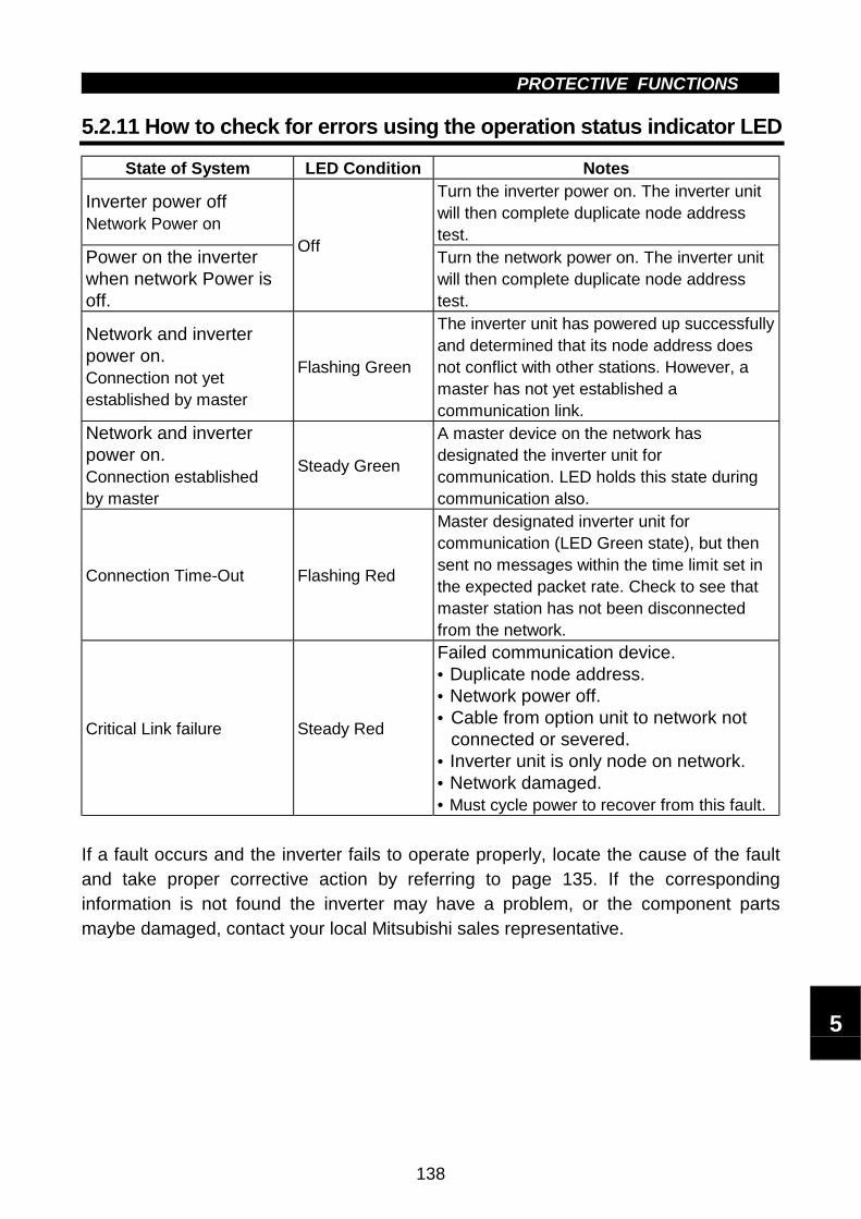
PROTECTIVE FUNCTIONS
138
5.2.11 How to check for errors using the operation status indicator LED
State of System LED Condition Notes
Inverter power offNetwork Power on
Turn the inverter power on. The inverter unitwill then complete duplicate node addresstest.
Power on the inverterwhen network Power isoff.
OffTurn the network power on. The inverter unitwill then complete duplicate node addresstest.
Network and inverterpower on.Connection not yetestablished by master
Flashing Green
The inverter unit has powered up successfullyand determined that its node address doesnot conflict with other stations. However, amaster has not yet established acommunication link.
Network and inverterpower on.Connection establishedby master
Steady Green
A master device on the network hasdesignated the inverter unit forcommunication. LED holds this state duringcommunication also.
Connection Time-Out Flashing Red
Master designated inverter unit forcommunication (LED Green state), but thensent no messages within the time limit set inthe expected packet rate. Check to see thatmaster station has not been disconnectedfrom the network.
Critical Link failure Steady Red
Failed communication device.• Duplicate node address.• Network power off.• Cable from option unit to network not
connected or severed.• Inverter unit is only node on network.• Network damaged.• Must cycle power to recover from this fault.
If a fault occurs and the inverter fails to operate properly, locate the cause of the faultand take proper corrective action by referring to page 135. If the correspondinginformation is not found the inverter may have a problem, or the component partsmaybe damaged, contact your local Mitsubishi sales representative.
5

PROTECTIVE FUNCTIONS
139
5.2.12 Inspecting display on parameter unit and status LED
In response to the occurrence of a fault, the display unit of the inverter automaticallydisplays the code of the detected fault and MNS Status LED shows the status of thedetected fault.
DisplayFR-PU04(Option)
LEDPossible Causes Check Corrective Action
E.OPT Blinking Red
Connection time-out,Master designatedinverter forcommunication, butsent no messageswithin time limit=4 ×EPR.
Master station hasnot beendisconnected fromnetwork.
Reset the inverter,Reconnect thenetwork,Master is up andrunning,Master sendsmessages withintime limit.
0.00 Steady Red
Duplicate nodeaddress;Network power off;Network cableoffline;Inverter is onlynode, not even aMaster is present;Network damaged.
No duplicate nodeaddress;Network power on;No damage tonetwork;All cables are inproper connection;Master is onnetwork.
Check required itemsin the left box,Reset the inverter,Restart the network.

5.3 Precautions for Maintenance and InspectionPROTECTIVE FUNCTIONS
140
5.3 Precautions for Maintenance and Inspection
The transistorized inverter is a static unit mainly consisting of semiconductor devices.Daily inspection must be performed to prevent any fault from occurring due to adverseinfluence by the operating environment, such as temperature, humidity, dust, dirt andvibration, changes in the parts with time, service life, and other factors.
5.3.1 Precautions for maintenance and inspection
When the maintenance/inspection of the inverter is to be performed in the DeviceNetTM
communication status, remove the terminal block for DeviceNetTM communicationsignals. Therefore, when more than 10 minutes have elapsed after power-off, makesure that the voltage across the main circuit terminals P - N (+ - -) of the inverter is30VDC or less using a tester, etc. Then, access the inverter for inspection.
5.3.2 Check items
(1) Daily inspection
! Check the following:1) Motor operation fault2) Improper installation environment3) Cooling system fault4) Unusual vibration and noise5) Unusual overheating and discoloration
! During operation, check the inverter input voltages using a meter.
(2) Cleaning
Always run the inverter in a clean state.When cleaning the inverter, gently wipe dirty areas with a soft cloth immersed inneutral detergent or ethanol.
Note: Do not use solvent, such as acetone, benzene, toluene and alcohol, as theywill cause the inverter surface paint to peel off.Do not use detergent or alcohol to clean the display and other sections of theparameter unit (FR-PU04) as these sections may deform.
5.3.3 Periodic inspection
Check the areas inaccessible during operation and requiring periodic inspection.1) Cooling system: .......Clean the air filter, etc.2) Screws and bolts: .....These parts may become loose due to vibration, temperature
changes, etc. Check that they are tightened securely andretighten as necessary.
3) Conductors and insulating materials: Check for corrosion and damage.4) Insulation resistance: Measure.5) Cooling fan, smoothing capacitor: Check and change if necessary.
5
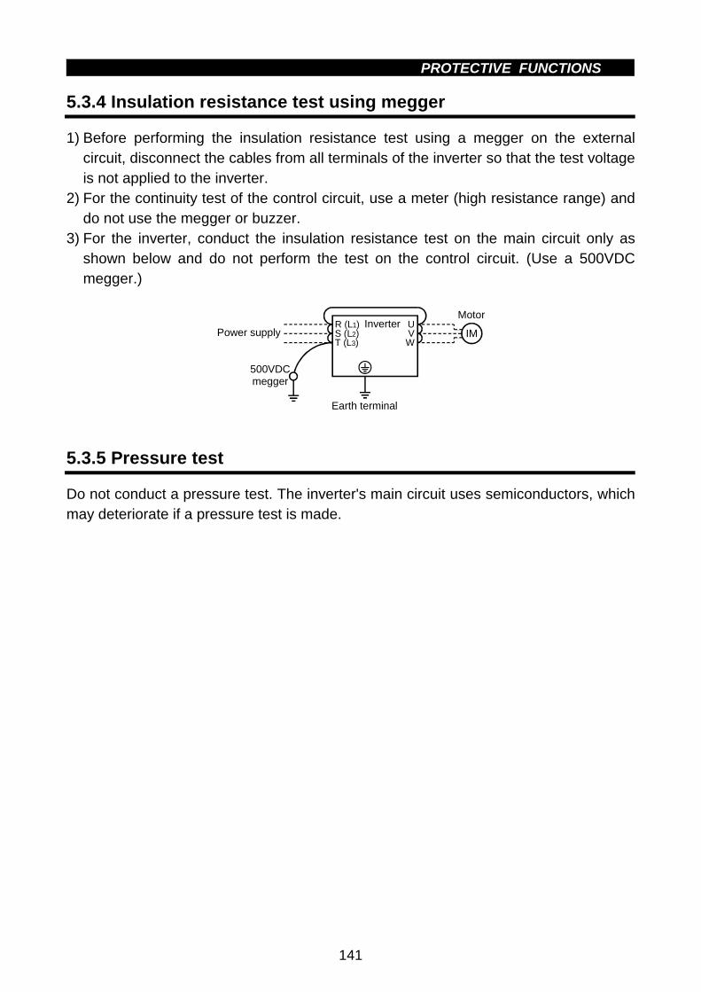
PROTECTIVE FUNCTIONS
141
5.3.4 Insulation resistance test using megger
1) Before performing the insulation resistance test using a megger on the externalcircuit, disconnect the cables from all terminals of the inverter so that the test voltageis not applied to the inverter.
2) For the continuity test of the control circuit, use a meter (high resistance range) anddo not use the megger or buzzer.
3) For the inverter, conduct the insulation resistance test on the main circuit only asshown below and do not perform the test on the control circuit. (Use a 500VDCmegger.)
R (L1)S (L2)T (L3)
UVW
Inverter
Earth terminal
500VDC megger
Power supply IM
Motor
5.3.5 Pressure test
Do not conduct a pressure test. The inverter's main circuit uses semiconductors, whichmay deteriorate if a pressure test is made.

PROTECTIVE FUNCTIONS
142
5.3.6 Daily and periodic inspection
IntervalPeriodic*
Are
a o
fIn
spec
tio
n
InspectionItem Description
Dai
ly
1 ye
ar
2 ye
ars Method Criterion Instrument
Surroundingenvironment
Check ambienttemperature, humidity,dust, dirt, etc.
' Refer to page 9.
Ambienttemperature:-10°C to +50°C,non-freezing.Ambienthumidity: 90%or less, non-condensing.
Thermo-meter,hygrometer,recorder
Overall unitCheck for unusualvibration and noise.
' Visual and auditorychecks.
No fault.Genera
l
Powersupplyvoltage
Check that maincircuit voltage isnormal.
'
Measure voltageacross inverterterminals R-S-T (L1-L2-L3).
Withinpermissible AC(DC) voltagefluctuation(Refer to page149)
Meter,digitalmultimeter
General
(1) Check with megger(across maincircuit terminalsand groundterminal).
(2) Check for loosescrews and bolts.
(3) Check for overheaton each part.
(4) Clean.
'
'
'
' (1) Disconnect allcables frominverter andmeasure acrossterminals R (L1),S (L2), T (L3), U,V, W and groundterminal withmegger.
(2) Retighten.(3) Visual check.
(1) 5MΩ ormore.
(2), (3) No fault.
500VDCclassmegger
Conductors,cables
(1) Check conductorsfor distortion.
(2) Check cablesheaths forbreakage.
'
'
(1), (2) Visual check.
(1), (2) No fault.
Terminalblock
Check for damage. ' Visual check No fault
Invertermodule
Convertermodule
Check resistanceacross terminals.
'
Disconnect cablesfrom inverter andmeasure acrossterminals R, S, T-P,N (L1, L2, L3 - +, −),and across U, V, W-P (+), N (−) with ameter with a 100Ωrange.
Refer to page144.
Analogmeter
Main
circu
it
Smoothingcapacitor
(1) Check for liquidleakage.
(2) Check for safetyvalve projectionand bulge.
(3) Measureelectrostaticcapacity.
'
'
'
(1), (2) Visual check.
(3) Measure withcapacity meter.
(1), (2) No fault.
(3) 85% or moreof ratedcapacity.
Capacitymeter
5

PROTECTIVE FUNCTIONS
143
Interval
Periodic*
Are
a o
fIn
spec
tio
n
InspectionItem Description
Dai
ly
1 ye
ar
2 ye
ars
Method Criterion Instrument
Contr
ol c
ircu
itP
rote
ctiv
e c
ircu
it
Operationcheck
(1) Check balance ofoutput voltagesacross phases withinverter operatedindependently.
(2) Perform sequenceprotectiveoperation test tomake sure there isno fault inprotective ordisplay circuits.
'
'
(1) Measure voltageacross inverteroutput terminalsU-V-W.
(2) Simulateconnection ofinverterprotective circuitoutput terminals.
(1) Phase-to-phasevoltagebalancewithin 4V for200V.
(2) Fault mustoccurbecause ofsequence.
Digitalmultimeter,rectifiertypevoltmeter
Coo
ling
syst
em
Cooling fan
(1) Check for unusualvibration andnoise.
(2) Check for looseconnection.
'
'
(1) Turn by handwith power off.
(2) Visual check.
No unusualvibration andunusual noise.
Display
(1) Check for LEDlamp blown.
(2) Clean.
'
'
(1) Lamps indicate indicator lamps on panel.
(2) Clean with rag.
(1) Check that lamps are lit.
Dis
pla
y
Meter
Check that reading isnormal.
' Check reading ofmeters on panel.
Must satisfyspecified andmanagementvalues.
Voltmeter,ammeter,etc.
General
(1) Check for unusualvibration andnoise.
(2) Check for unusualodor.
'
'
(1) Auditory,sensory, visualchecks.
(2) Check forunusual odor dueto overheat,damage, etc.
(1), (2) No fault.
Moto
r
Insulationresistance
Check with megger(across terminals andground terminal).
' Disconnect cablesfrom U, V, W,including motorcables.
5MΩ or more. 500Vmegger
* For periodic inspection, contact you nearest Mitsubishi sales representative.
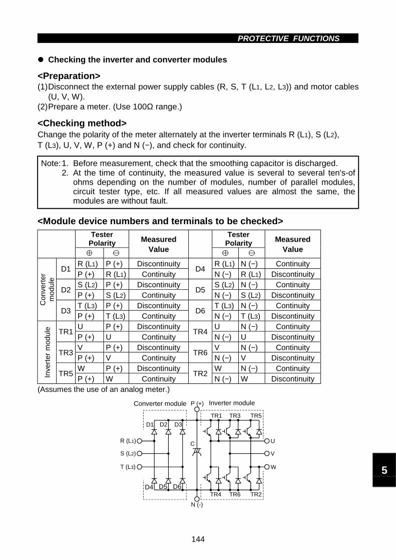
PROTECTIVE FUNCTIONS
144
"""" Checking the inverter and converter modules
<Preparation>(1)Disconnect the external power supply cables (R, S, T (L1, L2, L3)) and motor cables
(U, V, W).(2)Prepare a meter. (Use 100Ω range.)
<Checking method>Change the polarity of the meter alternately at the inverter terminals R (L1), S (L2),T (L3), U, V, W, P (+) and N (−), and check for continuity.
Note:1. Before measurement, check that the smoothing capacitor is discharged.2. At the time of continuity, the measured value is several to several ten's-of
ohms depending on the number of modules, number of parallel modules,circuit tester type, etc. If all measured values are almost the same, themodules are without fault.
<Module device numbers and terminals to be checked>Tester
PolarityTester
PolarityMeasuredValue
MeasuredValue
R (L1) P (+) Discontinuity R (L1) N (−) ContinuityD1
P (+) R (L1) ContinuityD4
N (−) R (L1) DiscontinuityS (L2) P (+) Discontinuity S (L2) N (−) Continuity
D2P (+) S (L2) Continuity
D5N (−) S (L2) Discontinuity
T (L3) P (+) Discontinuity T (L3) N (−) ContinuityConve
rter
module
D3P (+) T (L3) Continuity
D6N (−) T (L3) Discontinuity
U P (+) Discontinuity U N (−) ContinuityTR1
P (+) U ContinuityTR4
N (−) U DiscontinuityV P (+) Discontinuity V N (−) Continuity
TR3P (+) V Continuity
TR6N (−) V Discontinuity
W P (+) Discontinuity W N (−) Continuity
Inve
rter
module
TR5P (+) W Continuity
TR2N (−) W Discontinuity
(Assumes the use of an analog meter.)
Converter module Inverter module
D1 D2 D3
D4 D5 D6
TR1 TR3 TR5
TR4 TR6 TR2
U
V
W
R (L1)
S (L2)
T (L3)
C
P (+)
N (-)
5
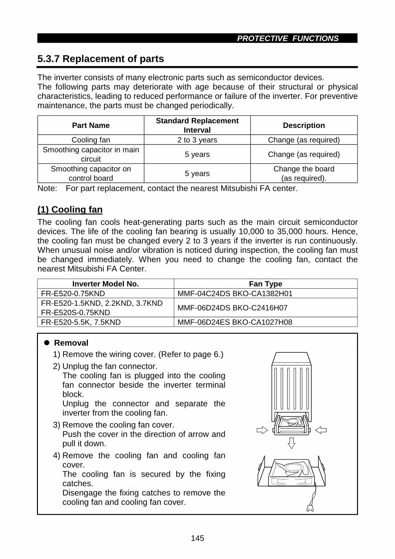
PROTECTIVE FUNCTIONS
145
5.3.7 Replacement of parts
The inverter consists of many electronic parts such as semiconductor devices.The following parts may deteriorate with age because of their structural or physicalcharacteristics, leading to reduced performance or failure of the inverter. For preventivemaintenance, the parts must be changed periodically.
Part NameStandard Replacement
IntervalDescription
Cooling fan 2 to 3 years Change (as required)Smoothing capacitor in main
circuit5 years Change (as required)
Smoothing capacitor oncontrol board
5 yearsChange the board
(as required).Note: For part replacement, contact the nearest Mitsubishi FA center.
(1) Cooling fanThe cooling fan cools heat-generating parts such as the main circuit semiconductordevices. The life of the cooling fan bearing is usually 10,000 to 35,000 hours. Hence,the cooling fan must be changed every 2 to 3 years if the inverter is run continuously.When unusual noise and/or vibration is noticed during inspection, the cooling fan mustbe changed immediately. When you need to change the cooling fan, contact thenearest Mitsubishi FA Center.
Inverter Model No. Fan TypeFR-E520-0.75KND MMF-04C24DS BKO-CA1382H01FR-E520-1.5KND, 2.2KND, 3.7KNDFR-E520S-0.75KND
MMF-06D24DS BKO-C2416H07
FR-E520-5.5K, 7.5KND MMF-06D24ES BKO-CA1027H08
"""" Removal1) Remove the wiring cover. (Refer to page 6.)
2) Unplug the fan connector.The cooling fan is plugged into the coolingfan connector beside the inverter terminalblock.Unplug the connector and separate theinverter from the cooling fan.
3) Remove the cooling fan cover.Push the cover in the direction of arrow andpull it down.
4) Remove the cooling fan and cooling fancover.The cooling fan is secured by the fixingcatches.Disengage the fixing catches to remove thecooling fan and cooling fan cover.
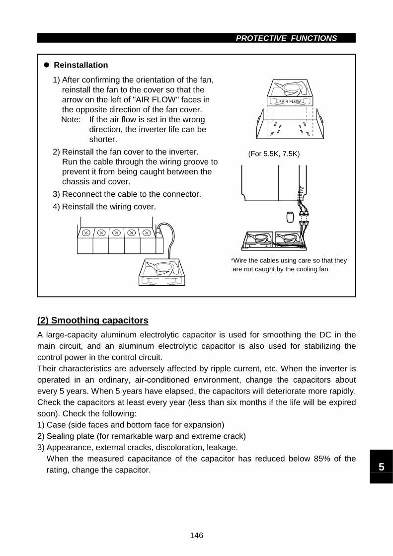
PROTECTIVE FUNCTIONS
146
"""" Reinstallation
1) After confirming the orientation of the fan,reinstall the fan to the cover so that thearrow on the left of "AIR FLOW" faces inthe opposite direction of the fan cover.Note: If the air flow is set in the wrong
direction, the inverter life can beshorter.
2) Reinstall the fan cover to the inverter.Run the cable through the wiring groove toprevent it from being caught between thechassis and cover.
3) Reconnect the cable to the connector.
4) Reinstall the wiring cover.
AIR FLOW
*Wire the cables using care so that they are not caught by the cooling fan.
(For 5.5K, 7.5K)
(2) Smoothing capacitors
A large-capacity aluminum electrolytic capacitor is used for smoothing the DC in themain circuit, and an aluminum electrolytic capacitor is also used for stabilizing thecontrol power in the control circuit.Their characteristics are adversely affected by ripple current, etc. When the inverter isoperated in an ordinary, air-conditioned environment, change the capacitors aboutevery 5 years. When 5 years have elapsed, the capacitors will deteriorate more rapidly.Check the capacitors at least every year (less than six months if the life will be expiredsoon). Check the following:1) Case (side faces and bottom face for expansion)2) Sealing plate (for remarkable warp and extreme crack)3) Appearance, external cracks, discoloration, leakage.
When the measured capacitance of the capacitor has reduced below 85% of therating, change the capacitor. 5

PROTECTIVE FUNCTIONS
147
5.3.8 Measurement of main circuit voltages, currents and powers
"""" Measurement of voltages and currentsSince the voltages and currents on the inverter power supply and output sides includeharmonics, accurate measurement depends on the instruments used and circuits measured.When instruments for commercial frequency are used for measurement, measure thefollowing circuits using the instruments given on the next page.
Inputvoltage
Inputcurrent
Outputvoltage
Outputcurrent
Ar
As
At
Vr
Vs
Vt
W11
W12
W13
Au
Av
Aw
Vu
Vv
Vw
W21
W22
V
R (L1)
S (L2)
T (L3)
U
V
W
Inverter
P (+) N (-)
3-phase power
To motor
Instrument types
+ −
:Moving-iron type
:Electrodynamometer type
:Moving-coil type
:Rectifier type
Three-phase 200Vpower input
Typical Measuring Points and Instruments
Note: Use FFT (Fast Fourier Transforms) to measure the output voltageaccurately.It cannot be measured accurately with a meter or general instrument.

PROTECTIVE FUNCTIONS
148
Measuring Points and Instruments
Item Measuring Point Measuring Instrument Remarks(Reference Measured Value)
Power supplyvoltage(V1)
Across R-S (L1-L2), S-T (L2-L3) and T-R (L3-L1)
Moving-iron type ACvoltmeter
Is the commercial power supply withinpermissible variation of AC voltage(Refer to page 149)
Power supply sidecurrent(I1)
R, S and T line currents(L1, L2 and L3 line currents)
Moving-iron type ACammeter
Power supply sidepower(P1)
At R (L1), S (L2) and T (L3),and across R-S (L1-L2), S-T(L2-L3) and T-R (L3-L1)
Electrodynamic typesingle-phase wattmeter
P1 = W11 + W12 + W13(3-wattmeter method)
Power supply sidepower factor(Pf1)
Calculate after measuring power supply voltage, power supply side current and power supply sidepower.
Pf1 = 100 %3V1 I1
P1
Output sidevoltage(V2)
Across U-V, V-W and W-U(Note 1)
(Cannot be measuredby moving-iron type)
Difference between phases is within±1% of maximum output voltage.
Output side current(I2) U, V and W line currents
Moving-iron type ACammeter
(Note 2)
Current should be equal to or less thanrated inverter current.Difference between phases is 10% orlower.
Output side power(P2)
At U, V and W, and across U-V and V-W
Electrodynamic typesingle-phase wattmeter
P2 = W21 + W222-wattmeter method (or 3-wattmetermethod)
Output side powerfactor(Pf2)
Calculate in similar manner to power supply side power factor.
Pf2 = 100 %3V2 I2
P2
Converter output Across P-N (+ - −) Moving-coil type(such as tester)
Inverter LED display is lit. 1.35 × V1Maximum 380V during regenerativeoperation
Reset Across RES (positive)-SD
Output stop Across MRS (positive)-SD
Moving-coil type(Meter, etc. may beused)(Internal resistance:50kΩ or larger)
20 to 30VDC when open.ON voltage: 1V or less S
D is
com
mon
Alarm signal Across A-CAcross B-C
Moving-coil type(such as a meter)
Continuity check<Normal> <Fault>
Across A-C: DiscontinuityContinuityAcross B-C: Continuity Discontinuity
Note: 1. Use FFT to measure the output voltage accurately. It can not be measured accurately with a meter orgeneral instrumentation.
2. If the carrier frequency exceeds 5kHz, do not use this instrument since using it may increase eddy-current loss produced in metal parts inside the instrument, leading to burnout.In this case, use an approximate effective value type instrument.
5

This chapter provides the "specifications" of this product.
Always read the instructions before using the equipment
6.1 Standard Specifications .......................................... 149
CHAPTER 6
SPECIFICATIONS
Chapter 1
Chapter 2
Chapter 3
Chapter 4
Chapter 5
Chapter 6

6.1 Standard SpecificationsSPECIFICATIONS
149
6 SPECIFICATIONS6.1 Standard Specifications
6.1.1 Model specifications
"""" 3-phase 200V power supply
Type FR-E520- KND 0.1 0.2 0.4 0.75 1.5 2.2 3.7 5.5 7.5Applicable motor capacity (kW)(Note 1) 0.1 0.2 0.4 0.75 1.5 2.2 3.7 5.5 7.5
Rated capacity (kVA) (Note 2) 0.3 0.6 1.2 2.0 3.2 4.4 7.0 9.5 13.1
Rated current (A) (Note 6) 0.8(0.8)
1.5(1.4)
3(2.5)
5(4.1)
8(7)
11(10)
17.5(16.5)
24(23)
33(31)
Overload capacity (Note 3) 150% 60s 200% 0.5s(inverse-time characteristics)O
utp
ut
Voltage (Note 4) Three phase, 200V to 240V 50Hz/60Hz
Rated input AC (DC) voltage,frequency
Three phase, 200V to 240V 50Hz/60Hz(280VDC, Note 7)
Permissible AC (DC) voltagefluctuation
170 to 264V 50Hz/60Hz(252 to 310VDC, Note 7)
Permissible frequencyfluctuation ±5%
Pow
er
supply
Power supply system capacity(kVA) (Note 5) 0.4 0.8 1.5 2.5 4.5 5.5 9 12 17
Protective structure (JEM1030) Enclosed type (IP20)Cooling system Self-cooling Forced air coolingApproximate weight (kg) 0.6 0.6 0.8 1.0 1.7 1.7 2.2 4.4 4.9
Note:1. The applicable motor capacity indicated is the maximum capacity applicablewhen a Mitsubishi 4-pole standard motor is used.
2. The rated output capacity indicated assumes that the output voltage is 230V.3. The overload capacity indicated in % is the ratio of the overload current to the
inverter's rated current. For repeated duty, allow time for the inverter andmotor to return to or below the temperatures under 100% load.
4. The maximum output voltage cannot exceed the power supply voltage. Themaximum output voltage may be set as desired below the power supplyvoltage. However, the crest value of the inverter output voltage remainsunchanged from the DC bus voltage.
5. The power supply capacity changes with the values of the power supply sideinverter impedances (including those of the input reactor and cables).
6. The rated output current in the parentheses applies when low acoustic noiseoperation is to be performed at the ambient temperature higher than 40°C withthe Pr. 72 (PWM frequency selection) value set to 2kHz or higher.
7. When using a DC power supply(1) The guideline for the power supply voltage fluctuation range is 280VDC
±10%, and usually use the power supply at or below 300VDC.(2) When DC power is switched on, a larger inrush current flows than in AC
power. The number of power-on times should be minimized.(3) 300VDC must be reserved to make the torque characteristic equal to when
AC power supply is used.

SPECIFICATIONS
150
6.1.2 Common specifications
Control systemSoft-PWM control/high carrier frequency PWM control can be selected.V/F control or general-purpose magnetic flux vector control can beselected.
Output frequency range 0.2 to 400Hz (starting frequency variable between 0 and 60Hz)Frequencysettingresolution
Digital input 0.01Hz (less than 100Hz), 0.1Hz (100Hz or more)
Frequencyaccuracy
Digital input Within 0.01% of set output frequency.
Voltage/frequencycharacteristic
Base frequency set as required between 0 and 400Hz. Constant torqueor variable torque pattern can be selected.
Starting torque150% or more (at 1Hz), 200% or more (at 3Hz) when general-purposemagnetic flux vector control or slip compensation is selected
Torque boost Manual torque boost, 0 to 30% may be set.
Acceleration/deceleration timesetting
0.01, 0.1 to 3600 s (acceleration and deceleration can be setindividually), linear or S-pattern acceleration/deceleration mode can beselected.
Regenerative(Note 3)
0.1K, 0.2K ... 150%, 0.4K, 0.75K ... 100%,1.5K ... 50%, 2.2K, 3.7K, 5.5K, 7.5K ... 20%Braking
torqueDC injection brake
Operation frequency (0 to 120Hz), operation time (0 to 10 s), operationvoltage (0 to 30%) variable
Current stall preventionoperation level
Operation current level can be set (0 to 200% variable), presence orabsence can be selected.
Voltage stall preventionoperation level
Operation level is fixed, presence or absence can be selected.
Fast-response current limitlevel
Operation level is fixed, presence or absence can be selected.
Frequencysetting signal
Digitalinput
Entered through DeviceNetTM communication or from the parameterunit.
Start signal Forward rotation and reverse rotation.Possible byDeviceNet orparameter unit
Alarm resetUsed to reset alarm output provided when protectivefunction is activated.
Possible byDeviceNet,parameter unitor (Pr. 192)
Multi-speed selection
Up to 15 speeds can be selected. (Each speed can beset between 0 and 400Hz, running speed can bechanged during operation from the parameter unit (FR-PU04).)
Second function selectionUsed to select second functions (acceleration time,deceleration time, torque boost, base frequency,electronic overcurrent protection).
Output stopInstantaneous shut-off of inverter output (frequency,voltage).
External thermal relayinput
Thermal relay contact input for use when the inverter isstopped by the external thermal relay.
Contr
ol s
peci
ficatio
ns
Input si
gnals
V/F-general-purposemagnetic flux switching
Used to switch between V/F control and general-purpose magnetic flux vector control from outside theinverter.
Possible withDeviceNet orinput terminal.
6

SPECIFICATIONS
151
Operation functions
Maximum/minimum frequency setting, frequency jump operation,external thermal relay input selection, automatic restart operation afterinstantaneous power failure, forward/reverse rotation prevention, slipcompensation, operation mode selection, offline auto tuning functionDeviceNet operation.
Contr
ol s
peci
ficatio
ns
Outp
ut si
gnals
Operating status
1 contact output (230VAC 0.3A, 30VDC 0.3A) can be selected frominverter running, up to frequency, frequency detection, overload alarm,zero current detection, output current detection, operation ready, minorfault and alarm.
Operatingstatus
Output voltage, output current, set frequency, running.Control paneldisplay Alarm
definitionAlarm definition is displayed when protective function is activated. 4alarm definitions are stored.D
ispla
y
LED display Power application (POWER), Alarm (ALARM), Operating status
Protective/alarm functions
Overcurrent shut-off (during acceleration, deceleration, constantspeed), regenerative overvoltage shut-off, undervoltage (Note 1),instantaneous power failure (Note 1), overload shut-off (electronicovercurrent protection), brake transistor alarm, output short circuit, stallprevention, brake resistor overheat protection, fin overheat, fan failure(Note 4), parameter error, PU disconnection, starting-time ground faultovercurrent protection.
Ambient temperature Constant torque : -10°C to +50°C (non-freezing)
Ambient humidity 90%RH or less (non-condensing)
Storage temperature (Note 2) -20°C to +65°CAmbience Indoors (no corrosive and flammable gases, oil mist, dust and dirt.)
Envi
ronm
ent
Altitude, vibrationMaximum 1000m above sea level for standard operation.After that derate by 3% for every extra 500m up to 2500m (91%).5.9m/s2 or less (conforming to JIS C 0040)
Note:1. When undervoltage or instantaneous power failure has occurred, alarmdisplay or alarm output is not provided but the inverter itself is protected.Overcurrent, regenerative overvoltage or other protection may be activatedat power restoration according to the operating status (load size, etc.)
2. Temperature applicable for a short period in transit, etc.3. The braking torque indicated is a short-duration average torque (which
varies with motor loss) when the motor alone is decelerated from 60Hz inthe shortest time and is not a continuous regenerative torque. When themotor is decelerated from the frequency higher than the base frequency,the average deceleration torque will reduce. Since the inverter does notcontain a brake resistor, use the optional brake resistor when regenerativeenergy is large. (The optional brake resistor cannot be used with 0.1K and0.2K.) A brake unit (BU) may also be used.
4. Not provided for the FR-E520-0.1KND to 0.4KND which are not equippedwith a cooling fan.

SPECIFICATIONS
152
6.1.3 Outline dimension drawings
"""" FR-E520-0.1KND, 0.2KND, 0.4KND, 0.75KND
6 5668
56
118
128
5
φ5 hole
5 4
55 D1
Wiring holes
30.6
D
Capacity D D1
Note: FR-E520-0.75KND is provided with cooling fan.(Unit: mm)
62
42
10
1095.6
95.6
127.6
147.6FR-E520-0.75KND
FR-E520-0.4KND
FR-E520-0.2KND
FR-E520-0.1KND
6

SPECIFICATIONS
153
"""" FR-E520-1.5KND, 2.2KND
29 685 8
150.630.6 55 6511
118
128
55
6 96108
6
2-φ5 hole
Wiring holes
Cooling fan ×1
(Unit: mm)

SPECIFICATIONS
154
"""" FR-E520-3.7KND
82.5 685 5
157.619.5
118
128
55
6 158170
6114.555.5
5530.6 72
2-φ5 hole
Wiring holes
Cooling fan ×1
(Unit: mm)
6

SPECIFICATIONS
155
"""" FR-E520-5.5KND, 7.5KND
10
57.5112.5
170
1116
8
6 96 68
164
180
8
824
4
26
0
8
189.6
19.6
2-φ6 hole
Wiring holes
Cooling fans × 2
(Unit: mm)

SPECIFICATIONS
156
6.1.4 DeviceNet specifications
1) Power supply
2) Standard
3) Network topology4) Transmission Media5) Maximum cable distance
6) Transmission speed7) Number of inverters connectable
• Communication power: supplied by DeviceNetpower supply, 11 to 28 V with a 10 A capacity
• Conforms to ODVA DeviceNet Specification,supports UCMM
• DeviceNet (linear bus with drop lines)• DeviceNet standard thick or thin cable• 500m at 125k baud with thick cable (see
DeviceNet specification for details onmaximum cable distance for different baudrates)
• 125kbps, 250kbps, 500kbps• 63 inverters with minimum of one node as a
master
6

A P P E N D I X
This chapter provides "supplementary information" for use
of this product.
Always read the instructions before using the equipment.
Appendix 1 Object Map ................................................ 157
Appendix 2 Electronic Data Sheets (EDS files)............. 180
Appendix 3 FR-E500 Series DeviceNet Type
Parameter Data.......................................... 181
Appendix 4 Data Code List ........................................... 185
APPENDIX

APPENDIX 1 Object Map
157
APPENDIXAPPENDIX 1 Object Map
This section describes the DeviceNet object definitions of the FR-E500KND. For detailsof the definitions, please consult the DeviceNet documentation available from ODVA.In the following tables, Get and Set mean:
Get: Read from inverterSet: Write to inverter
1. Class 0x01 - Identity Object
(1) Class 0x01 Attributes - Instance 0
No. Access Attribute Type Value1 Get Revision Word 12 Get Maximum Instance Word 16 Get Maximum Class Attributes Word 77 Get Maximum Instance Attributes Word 7
(2) Class 0x01 Services - Instance 0
Service Code Service0x0E Get Attribute Single
(3) Class 0x01 Instance Attributes - Instance 1
No. Access Attribute Type Value1 Get Vendor ID Word 82 (0x0052)2 Get Product Type Word 0x00023 Get Product Code Word 501 (0x1F5)4 Get Revision Word 1.YYY (Note 1)5 Get Status Word 0x00006 Get Serial Number Word xxxxxxxx (Note 2)7 Get Name Word E500 (Note 3)
Note 1. The upper byte of the read hexadecimal word data indicates the integerpart (major revision) and its lower byte indicates the fraction part (minorrevision). For example, the read data of 0x010A means version 1.010.
2. The value changes with the product.3. The actual data stored are 0x04, 0x45, 0x35, 0x30 and 0x30. The first
0x04 indicates the 4-byte data and the others indicate "E500" in ASCII
(4) Class 0x01 Instance Services - Instance 1
Service Code Service Description
0x05 Reset0-Power Reset1-Parameter All Clear and Power Reset
0x0E Get Attribute Single

158
2. Class 0x03 - DeviceNet Object
(1) Class 0x03 Attributes - Instance 0
Note: Not applicable to the FR-E500KND.
(2) Class 0x03 Services - Instance 0
Note: Not applicable to the FR-E500KND.
(3) Class 0x03 Instance Attributes - Instance 1No. Access Attribute Value1 Get/Set Node Address Setting (Note) 0 to 63
2 Get/SetBaud Rate Setting (Note) (0: 125kbps, 1:250kbps, 2: 500kbps)
0 to 2
3 Get/Set
Bus Off Interrupt0: Hold CAN chip in reset state on
detection of Bus Off.1: Reset CAN chip and continues
communication on detection of BusOff.
0 to 1
4 Get/SetBus Off Counter (the number of timeswhen the CAN chip resulted in bus off iscounted)
0 to 255
5 Get Allocation Information 0 to 0xFFFF8 Get MAC ID Switch Value 0 to 639 Get Actual Value of Baud Rate 0 to 2
Note: Class 0x67 Instance 1 Attributes 45 and 46 may also be used to performread.
(4) Class 0x03 Instance Services - Instance 1Service Code Service
0x4B Allocate0x4C Release0x0E Get Attribute Single0x10 Set Attribute Single

159
3. Class 0x04 - Assembly Object
(1) Class 0x04 - Output Instance 20Byte Bit 7 Bit 6 Bit 5 Bit 4 Bit 3 Bit 2 Bit 1 Bit 0
0 − − − − − FaultReset
− RunFwd
1 −2 Speed Reference (Low Byte)
Instance0x1420
3 Speed Reference (High Byte)
(2) Class 0x04 - Output Instance 21 (Default)Byte Bit 7 Bit 6 Bit 5 Bit 4 Bit 3 Bit 2 Bit 1 Bit 0
0 − NetRef NetCtrl − − FaultReset
RunRev
RunFwd
1 −2 Speed Reference (Low Byte)
Instance0x1521
3 Speed Reference (High Byte)
(3) Class 0x04 - Output Instance 126Byte Bit7 Bit6 Bit5 Bit4 Bit3 Bit2 Bit1 Bit0
0Write
ParamNetRef NetCtrl − − Fault
ResetRunRev
RunFwd
1 002 (Low Byte) Speed Ref or Parameter Write Data3 (High Byte) Speed Ref or Parameter Write Data4 Parameter Class
Instance0x7E126
5 Parameter Attribute No.Note 1. Before directing the inverter via the network, always turn on the bits of
"NetCtrl" and "NetRef". If they are off, the inverter will not accept thedirectives even in the network operation mode.
2. When issuing a command, always hold the forward/reverse rotation flag inthe present running status. Transmitting a wrong status will change therunning status.(Example: The inverter will stop the output if bit 0 is turned off during theinverter forward rotation command.)
3. Always set "0" in Byte 1 of output instance 126. The inverter will notrecognize any other value as normal data.
Output Instance 126 (0x7E) provides write/read parameter access control of theparameter class, the parameter attribute No., and the parameter data for a writeoperation.
Output Instance 126 must be used together with Input Instance 176 in thoseapplications requiring parameter access.
Output Instance 126 utilizes 6 data bytes.

160
The Output Instance 126 bytes operate in the following manner:Byte 0:
Bit 7 - If Write Parameter=1, the Parameter Write Data is written to the parameterand the rest of the parameter is ignored.
Bit 7 - If Write Parameter=0, the Speed Ref in RPM is set, and the rest of thecommand byte is executed.
Bit 6 - If NetRef=1, the Speed Ref is taken from Byte 2 and Byte 3. If 0, Speed Refis not incorporated.
Bit 5 - If NetControl = 0, the forward run, reverse run and error reset are valid. If 1,these are not validated.
Bit 4 - Not Used.Bit 3 - Not Used.Bit 2 - If Fault Reset makes a transition from 0 to 1 and there is an error in the
inverter, the inverter will reset.Bit 1 - If Run Rev=1 and Run Fwd=0, the drives rotates in the reverse direction.Bit 0 - If Run Fwd=1 and Run Rev=0, the drives spins in the forward direction.
Note: Net Control must=1 for Bits 2, 1, 0 to have any affect.
Byte 1: Must be 00.Byte 2: Low Byte of the Speed Ref or Data Value.Byte 3: High Byte of the Speed Ref or Data Value.Byte 4: Parameter Class, e.g. 0x2A, 0x66, 0x67.Byte 5: Parameter Attribute Number, e.g. 0x0A, 0x65.
(4) Class 0x04 - Input Instance 70Byte Bit 7 Bit 6 Bit 5 Bit 4 Bit 3 Bit 2 Bit 1 Bit 0
0 − − − − − Run (1)Fwd
− Faulted
1 −2 Speed Actual (Low Byte)
Instance0x4670
3 Speed Actual (High Byte)
(5) Class 0x04 - Input Instance 71 (Default)Byte Bit 7 Bit 6 Bit 5 Bit 4 Bit 3 Bit 2 Bit 1 Bit 0
0At RefSpeed
RefFromNet
CtrlFromNet
ReadyRun (2)
RevRun (1)
Fwd− Faulted
1 −2 Speed Actual (Low Byte)
Instance0x4771
3 Speed Actual (High Byte)

161
(6) Class 0x04 - Input Instance 176Byte Bit 7 Bit 6 Bit 5 Bit 4 Bit 3 Bit 2 Bit 1 Bit 0
0At RefSpeed
RefFromNet
ControlFromNet
ReadyRun (2)
RevRun (1)
Fwd− Faulted
1 002 Speed Actual (Low Byte)3 Speed Actual (High Byte)4 Parameter Read (Low Byte)
Instance0xB0176
5 Parameter Read (High Byte)
The Input Instance 176 (0xB0) provide 16 bits of parameter data.Input Instance 176 must be used together with Output Instance 126 in thoseapplications requiring parameter access.
Input Instance 176 utilizes 6 data bytes.
The Input Instance 176 bytes operates in the following manner:Byte 0:
Bit 7 - At Ref Speed - 1: The drive is very close to or at the Ref Speed.Bit 6 - Ref From Net - 1: Speed setting comes from the DeviceNet master.Bit 5 - Control From Net - 1: Fault Reset, Run Rev, Run Fwd come from the
DeviceNet Master.Bit 4 - Ready.Bit 3 - Run Rev - 1: Drive is rotating in the reverse direction.Bit 2 - Run Fwd - 1: Drive is rotating in the forward direction.Bit 1 - Not Supported.Bit 0 - 1: The drive is in a fault state.
Byte 1: Must be 00.Byte 2: Low Byte of the Speed Actual.Byte 3: High Byte of the Speed Actual.Byte 4: Low Byte of Parameter.Byte 5: High Byte of Parameter.
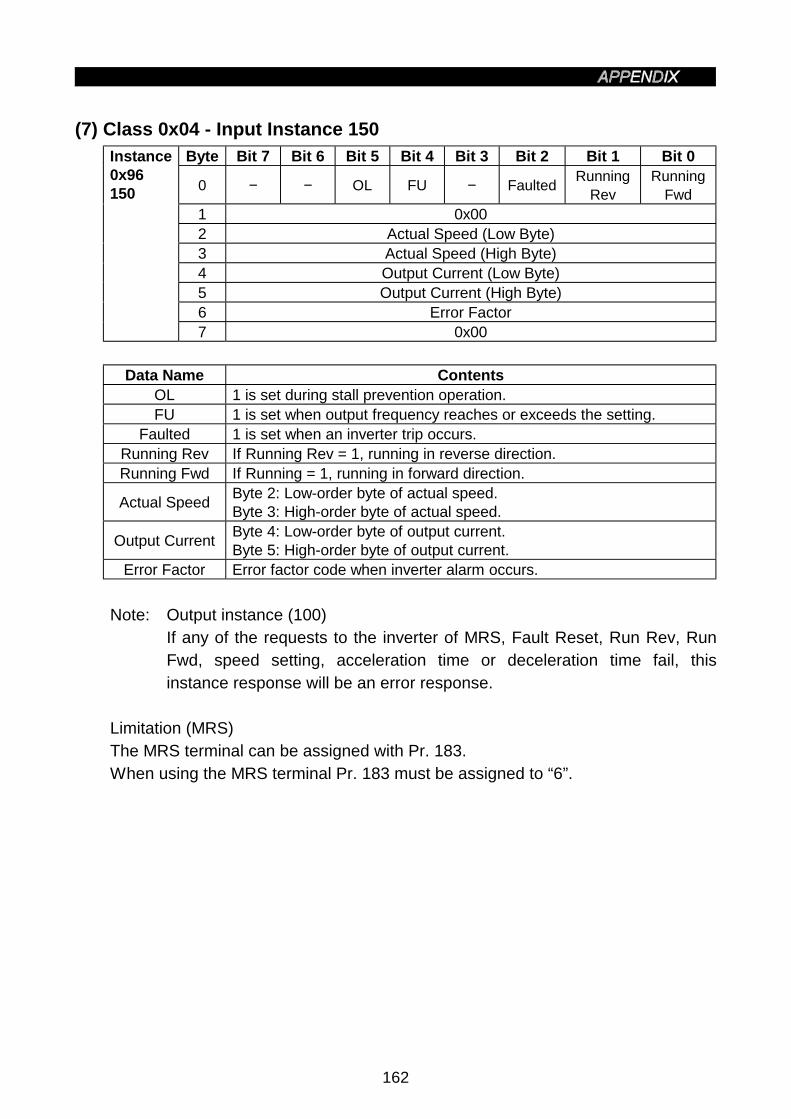
162
(7) Class 0x04 - Input Instance 150Byte Bit 7 Bit 6 Bit 5 Bit 4 Bit 3 Bit 2 Bit 1 Bit 0
0 − − OL FU − FaultedRunning
RevRunning
Fwd1 0x002 Actual Speed (Low Byte)3 Actual Speed (High Byte)4 Output Current (Low Byte)5 Output Current (High Byte)6 Error Factor
Instance0x96150
7 0x00
Data Name ContentsOL 1 is set during stall prevention operation.FU 1 is set when output frequency reaches or exceeds the setting.
Faulted 1 is set when an inverter trip occurs.Running Rev If Running Rev = 1, running in reverse direction.Running Fwd If Running = 1, running in forward direction.
Actual SpeedByte 2: Low-order byte of actual speed.Byte 3: High-order byte of actual speed.
Output CurrentByte 4: Low-order byte of output current.Byte 5: High-order byte of output current.
Error Factor Error factor code when inverter alarm occurs.
Note: Output instance (100)If any of the requests to the inverter of MRS, Fault Reset, Run Rev, RunFwd, speed setting, acceleration time or deceleration time fail, thisinstance response will be an error response.
Limitation (MRS)The MRS terminal can be assigned with Pr. 183.When using the MRS terminal Pr. 183 must be assigned to “6”.

163
(8) Class 0x04 - Output Instance 100Byte Bit 7 Bit 6 Bit 5 Bit 4 Bit 3 Bit 2 Bit 1 Bit 0
0Write
ParamNetRef
NetCtrl
− MRSFaultReset
RunRev
RunFwd
1 0x002 Speed Reference (Low Byte)3 Speed Reference (High Byte)4 Acceleration Time (Low Byte)5 Acceleration Time (High Byte)6 Deceleration Time (Low Byte)
OutputInstance0x64100
7 Deceleration Time (High Byte)
Data Name Contents
Write Param
1: The acceleration/deceleration time value is the value set with Byte4, Byte 5, Byte 6 and Byte 7.(As this is written while running, writing is enabled only when Pr. 77is 2.)
0: The acceleration/deceleration time value is not written.
Net Ref1: The speed reference is the value set with Byte 2 and Byte 3.0: The speed reference is the value set from the parameter unit.
Net Ctrl
1: MRS, Fault Reset, Run Rev and Run Fwd are operated withcommunications.
0: MRS, Fault Reset, Run Rev and Run Fwd are operated with theinverter.
Fault ResetIf Fault Reset makes a transition from 0 to 1 and there is an error inthe inverter, the inverter will reset.
MRS1: The inverter output is shut off.0: The inverter output shut off is canceled.
Run Rev If Run Rev is 1 and Run Fwd is 0, runs in reverse direction.Run Fwd If Run Fwd is 1 and Run Rev is 0, runs in forward direction.Speed
ReferenceByte 2: Low-order byte of speed reference.Byte 3: High-order byte of speed reference.
AccelerationTime
Byte 4: Low-order byte of acceleration time.Byte 5: High-order byte of acceleration time.
(Acceleration time = Pr. 7)
DecelerationTime
Byte 6: Low-order byte of deceleration time.Byte 7: High-order byte of deceleration time.
(Deceleration time = Pr. 8)

164
4. Class 0x05 - DeviceNet Connection Object
The FR-E500KND supports only Polled I/O and Explicit Messaging. It does notsupport Bit-Strobed I/O.
(1) Class 0x05 Attributes - Instance 0
Note: Not applicable to the FR-E500KND.
(2) Class 0x05 Services - Instance 0
Note: Not applicable to the FR-E500KND.
(3) Class 0x05 Instance Attributes Instance 1 - Explicit Messaging
No. Access Attribute Value
1 Get
State 0 - Non-existent 1 - Configuring2 - Waiting for connection ID3 - Established 4 - Timed out5 - Deferred delete
0 to 5
2 GetInstance Type 0 - Explicit Messaging
connection1 - Polled I/O connection
0 to 1
3 GetTransport Trigger Class0x83: Server Transport Class 3
0x83
4 Get Produced Connection ID 0 to 0x7F05 Get Consumed Connection ID 0 to 0x7F0
6 GetInitial Comm Characteristics(Define the send and receive messagegroups.)
0x21
7 GetProduced Connection Size(Max. number of bytes of sendablemessage body)
7
8 GetConsumed Connection Size(Max. number of bytes of receivablemessage body)
7
9 Get/Set Expected Packet Rate (EPR) Default 2504
12 Get
Watchdog Action0 - Transition to time out1 - Auto delete 2 - Auto reset3 - Deferred delete
0 to 3
13 Get Produced Connection Path Length 014 Get Produced Connection Path (Variable)15 Get Consumed Connection Path Length 016 Get Consumed Connection Path (Variable)
Note: Refer to Vol. I: 5-4 of DeviceNet Specifications for details.

165
(4) Class 0x05 Instance Attributes Instance 2 - Polled I/O
No. Access Attribute Value1 Get State 0 to 52 Get Instance Type 0 to 13 Get Transport Trigger Class 0x834 Get Produced Connection ID 0 to 0x7F05 Get Consumed Connection ID 0 to 0x7F06 Get Initial Comm Characteristics 0x017 Get Produced Connection Size 48 Get Consumed Connection Size 49 Get/Set Expected Packet Rate (EPR) Default 0
12 Get/Set Watchdog Action 0 to 313 Get/Set Produced Connection Path Length 014 Get/Set Produced Connection Path (Variable)15 Get/Set Consumed Connection Path Length 016 Get/Set Consumed Connection Path (Variable)
Note: 1. Depends on the communication data used. 4 for use of output instances20, 21 and input instances 70, 71 or 6 for use of output instance 126 andinput instance 176.
2. Refer to Vol. I: 5-4 of DeviceNet Specifications for details.
(5) Class 0x05 Instance Attributes Instance 3 - Explicit messaging
No. Access Attribute Value1 Get State 0 to 52 Get Instance Type 0 to 13 Get Transport Trigger Class 0x834 Get Produced Connection ID 0 to 0x7F05 Get Consumed Connection ID 0 to 0x7F06 Get Initial Comm. Characteristics 0x337 Get Produced Connection Size 78 Get Consumed Connection Size 79 Get Expected Packet Rate (EPR) Default 2504
12 Get Watchdog Action 0 to 313 Get Produced Connection Path Length 014 Get/Set Produced Connection Path (Variable)15 Get Consumed Connection Path Length 016 Get/Set Consumed Connection Path (Variable)
Refer to Vol.I: 5-4 of DeviceNet Specifications for details.
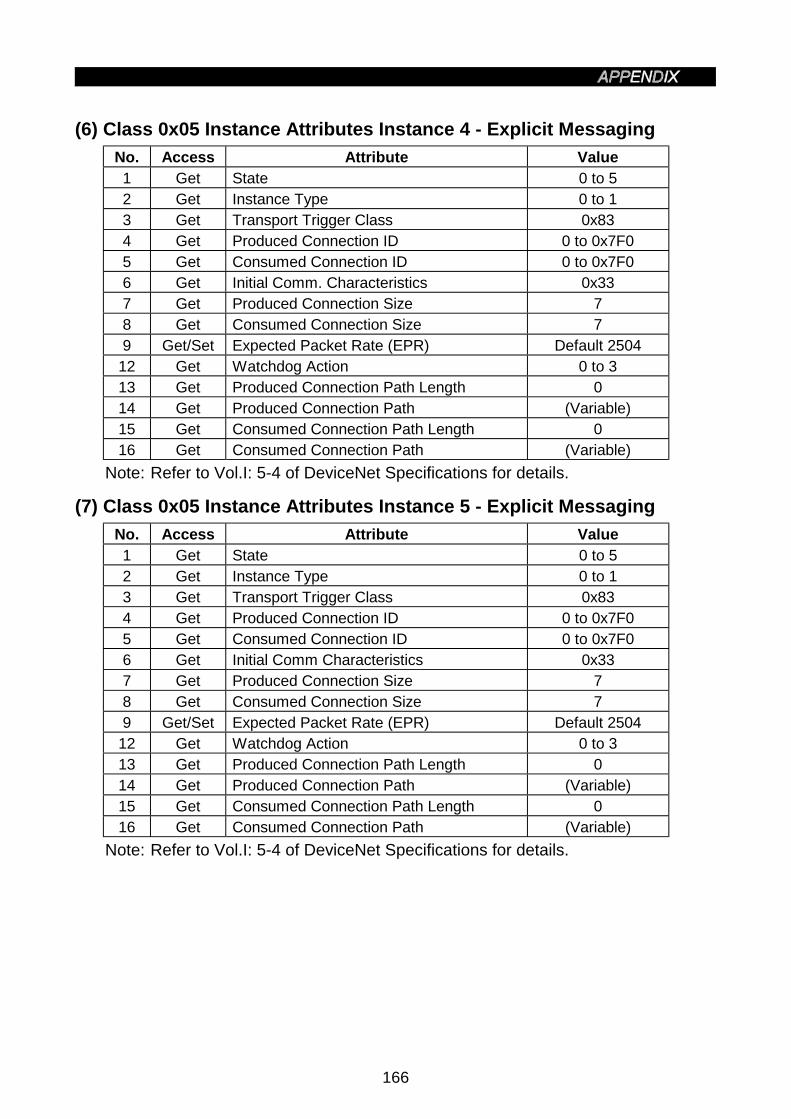
166
(6) Class 0x05 Instance Attributes Instance 4 - Explicit Messaging
No. Access Attribute Value1 Get State 0 to 52 Get Instance Type 0 to 13 Get Transport Trigger Class 0x834 Get Produced Connection ID 0 to 0x7F05 Get Consumed Connection ID 0 to 0x7F06 Get Initial Comm. Characteristics 0x337 Get Produced Connection Size 78 Get Consumed Connection Size 79 Get/Set Expected Packet Rate (EPR) Default 2504
12 Get Watchdog Action 0 to 313 Get Produced Connection Path Length 014 Get Produced Connection Path (Variable)15 Get Consumed Connection Path Length 016 Get Consumed Connection Path (Variable)
Note: Refer to Vol.I: 5-4 of DeviceNet Specifications for details.
(7) Class 0x05 Instance Attributes Instance 5 - Explicit Messaging
No. Access Attribute Value1 Get State 0 to 52 Get Instance Type 0 to 13 Get Transport Trigger Class 0x834 Get Produced Connection ID 0 to 0x7F05 Get Consumed Connection ID 0 to 0x7F06 Get Initial Comm Characteristics 0x337 Get Produced Connection Size 78 Get Consumed Connection Size 79 Get/Set Expected Packet Rate (EPR) Default 2504
12 Get Watchdog Action 0 to 313 Get Produced Connection Path Length 014 Get Produced Connection Path (Variable)15 Get Consumed Connection Path Length 016 Get Consumed Connection Path (Variable)
Note: Refer to Vol.I: 5-4 of DeviceNet Specifications for details.
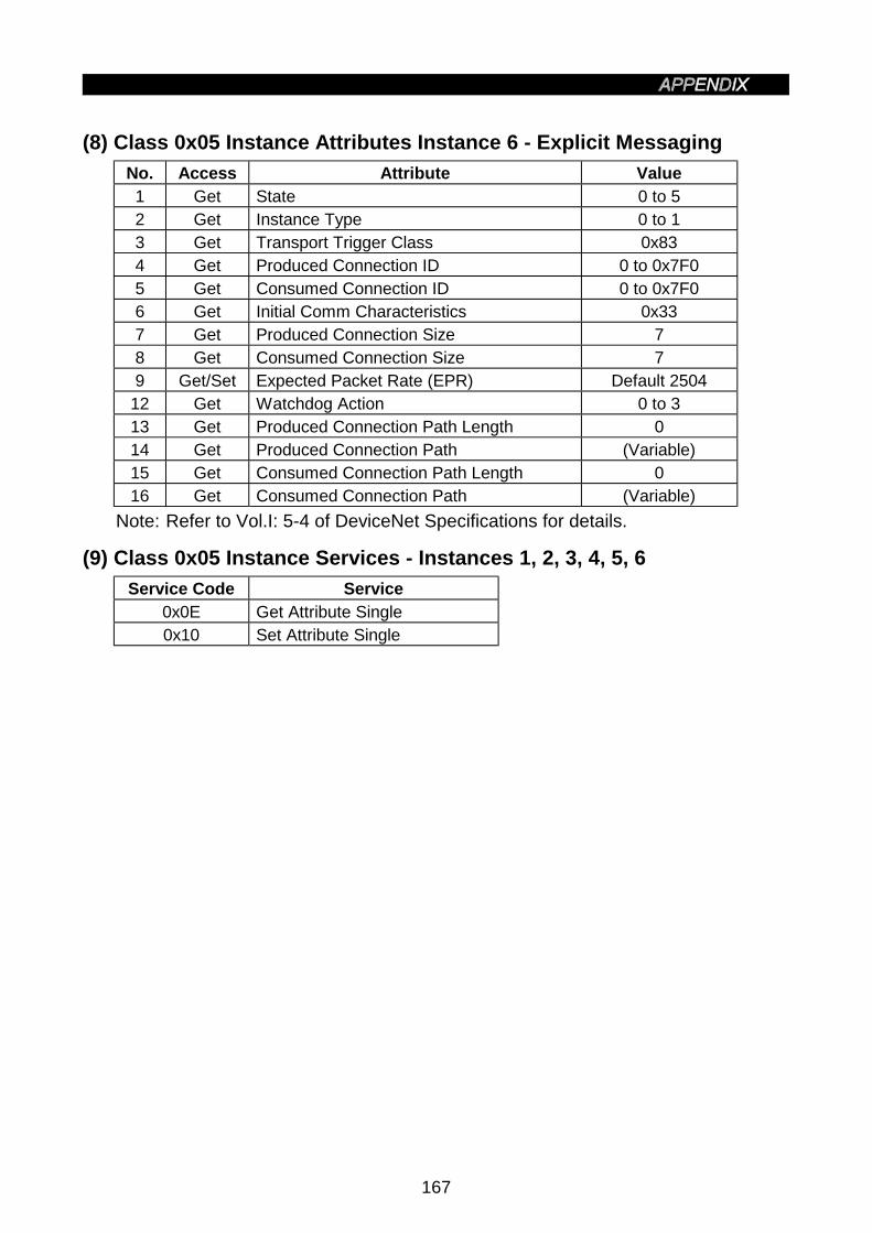
167
(8) Class 0x05 Instance Attributes Instance 6 - Explicit Messaging
No. Access Attribute Value1 Get State 0 to 52 Get Instance Type 0 to 13 Get Transport Trigger Class 0x834 Get Produced Connection ID 0 to 0x7F05 Get Consumed Connection ID 0 to 0x7F06 Get Initial Comm Characteristics 0x337 Get Produced Connection Size 78 Get Consumed Connection Size 79 Get/Set Expected Packet Rate (EPR) Default 2504
12 Get Watchdog Action 0 to 313 Get Produced Connection Path Length 014 Get Produced Connection Path (Variable)15 Get Consumed Connection Path Length 016 Get Consumed Connection Path (Variable)
Note: Refer to Vol.I: 5-4 of DeviceNet Specifications for details.
(9) Class 0x05 Instance Services - Instances 1, 2, 3, 4, 5, 6
Service Code Service0x0E Get Attribute Single0x10 Set Attribute Single

168
5. Class 0x28 - Motor Data Object
(1) Class 0x28 Attributes - Instance 0
Note: Not applicable to the FR-E500KND.
(2) Class 0x28 Services - Instance 0
Note: Not applicable to the FR-E500KND.
(3) Class 0x28 Instance Attributes Instance 1
No. Access Attribute Value3 Get/Set Motor Type 7 (Induction Motor)
6 Get/Set Rated Current,Setting Value for
Pr. 9
7 Get/Set Rated Voltage,Setting Value for
Pr. 83
9 Get/Set Rated Frequency,Setting Value for
Pr. 81
15 Get/Set Base Speed, cf.Setting Value for
Pr. 3
Note: Refer to Vol. 2: 6-29 of DeviceNet Specifications for details.
(4) Class 0x28 Instance Services
Service Code Service0x0E Get Attribute Single0x10 Set Attribute Single

169
6. Class 0x29 - Control Supervisor Object
(1) Class 0x29 Attributes - Instance 0Note: Not applicable to the FR-E500KND.
(2) Class 0x29 ServicesNote: Not applicable to the FR-E500KND.
(3) Class 0x29 Instance Attributes Instance 1No. Access Attribute Value
3 Get/SetForward Rotation
0: Stop 1: Forward0 to 1
4 Get/SetReverse Rotation
0: Stop 1:Reverse0 to 1
6 Get
Status 0: Vendor specific1: Start up 2: Not Ready3: Ready 4: Enabled5: Stopping 6: Fault stop7: Faulted
0 to 7
7 GetForward command
0: Without forward rotation command1: With forward rotation command
0 to 1
8 GetReverse run command
0: Without reverse rotation command1: With reverse rotation command
0 to 1
9 GetReady 0: Communication disabled
1: Communication enabled0 to 1
10 GetFaulted 0: No error
0→1: Error occurrence (latch)0 to 1
12 Get/SetError Reset (Note 1)
0: Reset cancel0→1: Reset execution
0 to 1
15 GetOperation Command Source Monitor (Note 2)
0: Other than communication1: Communication
0 to 1
16 Get/SetFault Mode (Operation performed whencommunication stops dead)
0: Error has occurred and stopped0 to 1
140 Get/Set Input Assembly 70, 71, 150, 176141 Get/Set Output Assembly 20, 21, 100, 126
Note 1. After setting data to 1 and executing a reset, a reset cannot be executedagain unless the data is set to 0 once to cancel a reset.
2. This data is updated only after an inverter reset or operation cycle.3. Refer to Vol. II: 6-29 of DeviceNet Specifications for details.
(4) Class 0x29 Instance ServicesService Code Service
0x05Reset Object Information.(Does not perform inverter reset)
0x0E Get Attribute Single0x10 Set Attribute Single
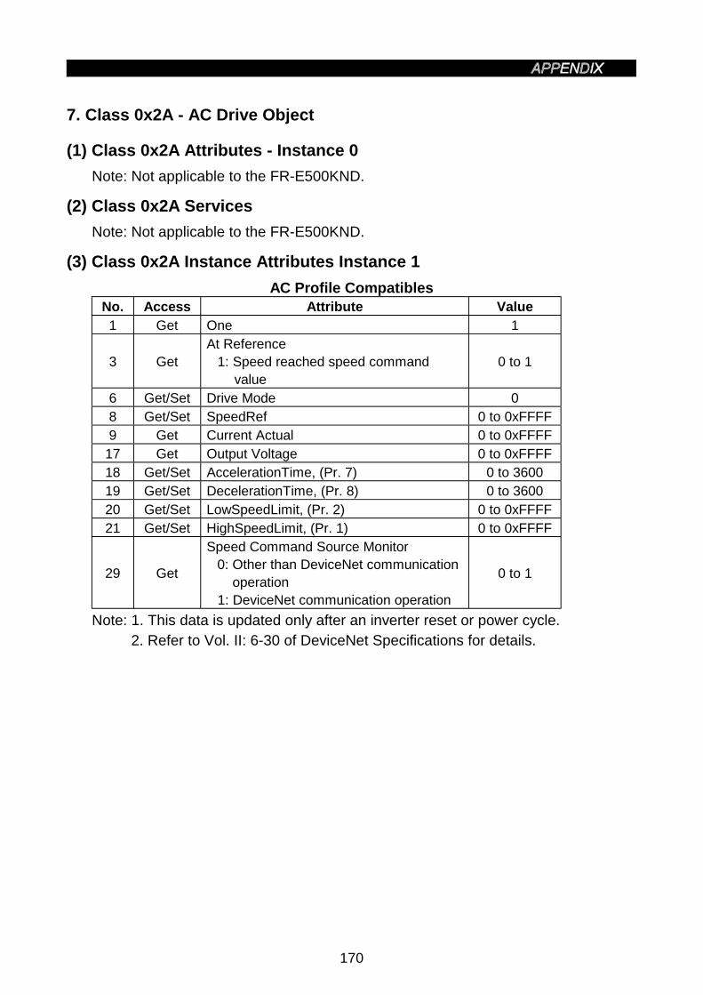
170
7. Class 0x2A - AC Drive Object
(1) Class 0x2A Attributes - Instance 0
Note: Not applicable to the FR-E500KND.
(2) Class 0x2A Services
Note: Not applicable to the FR-E500KND.
(3) Class 0x2A Instance Attributes Instance 1
AC Profile CompatiblesNo. Access Attribute Value1 Get One 1
3 GetAt Reference
1: Speed reached speed commandvalue
0 to 1
6 Get/Set Drive Mode 08 Get/Set SpeedRef 0 to 0xFFFF9 Get Current Actual 0 to 0xFFFF
17 Get Output Voltage 0 to 0xFFFF18 Get/Set AccelerationTime, (Pr. 7) 0 to 360019 Get/Set DecelerationTime, (Pr. 8) 0 to 360020 Get/Set LowSpeedLimit, (Pr. 2) 0 to 0xFFFF21 Get/Set HighSpeedLimit, (Pr. 1) 0 to 0xFFFF
29 Get
Speed Command Source Monitor0: Other than DeviceNet communication
operation1: DeviceNet communication operation
0 to 1
Note: 1. This data is updated only after an inverter reset or power cycle.2. Refer to Vol. II: 6-30 of DeviceNet Specifications for details.

171
The following variables and parameters are specific to the FR-E500KND.
FR-E500KND System Environment VariablesNo. Access Attribute Value101 Set Inverter reset 1102 Set Parameter Clear 0x965A103 Set Parameter All Clear 0x99AA105 Set Parameter Clear (Ex Com Pr) 0x5A96106 Set Parameter All Clear (Ex Com Pr) 0xAA99112 Get/Set Running Frequency (RAM) (Note) 30.00Hz
113 Set Running Frequency (E2PROM) (Note) 30.00Hz
114 Get/Set Inverter Status/Control Input Command 0 to 0xFFFF
120 Get/Set
Operating Mode/Inverter Config(1) Get 1: PU operation
4: DeviceNet communicationoperation
(2) Set 0x11: PU operation0x14: DeviceNet communication
operation
−
Note: Write to No.112 and No.113 can be read out from No.112.
FR-E500KND Real Time ParametersNo. Access Attribute Value
141 Get/SetAlarm History 1 (Note)/Alarm History AllClear
0 to 0xFFFF
142 Get Alarm History 2 (Note) 0 to 0xFFFF143 Get Alarm History 3 (Note) 0 to 0xFFFF144 Get Alarm History 4 (Note) 0 to 0xFFFF145 Get Alarm History 5 (Note) 0 to 0xFFFF146 Get Alarm History 6 (Note) 0 to 0xFFFF147 Get Alarm History 7 (Note) 0 to 0xFFFF148 Get Alarm History 8 (Note) 0 to 0xFFFF
170 GetOutput frequency(Minimum setting increments: 0.01Hz)
0 to 0xFFFF
171 GetOutput Current(Minimum setting increments: 0.01A)
0 to 0xFFFF
172 GetOutput Voltage(Minimum setting increments: 0.1V)
0 to 0xFFFF
Note: For the alarm history, refer to the alarm code list on the next page.

172
Alarm Code ListCode Definition Code Definition Code Definition0x10 OC1 0x80 GF 0xF5 E50x11 OC2 0x81 LF 0xF6 E60x12 OC3 0x90 OHT 0xF7 E70x20 OV1 0xB0 PE 0xF8 E80x21 OV2 0xB1 PUE 0xF9 E90x22 OV3 0xB2 RET 0xFA E100x30 THT 0xC0 CPU 0xFB E110x31 THM 0xF0 E0 0xFC E120x40 FIN 0xF1 E1 0xFD E130x41 FAN 0xF2 E2 0xFE E140x60 OLT 0xF3 E3 0xFF E150x70 BE 0xF4 E4
Note: Please refer to Section for explanation of Alarm Codes.
(4) Class 0x2A Instance Services
Service Code Service
0x0E Read Attribute Value
0x10 Write Attribute Value
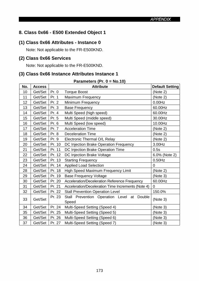
173
8. Class 0x66 - E500 Extended Object 1
(1) Class 0x66 Attributes - Instance 0
Note: Not applicable to the FR-E500KND.
(2) Class 0x66 Services
Note: Not applicable to the FR-E500KND.
(3) Class 0x66 Instance Attributes Instance 1
Parameters (Pr. 0 = No.10)No. Access Attribute Default Setting10 Get/Set Pr. 0 Torque Boost (Note 2)11 Get/Set Pr. 1 Maximum Frequency (Note 2)12 Get/Set Pr. 2 Minimum Frequency 0.00Hz13 Get/Set Pr. 3 Base Frequency 60.00Hz14 Get/Set Pr. 4 Multi Speed (high speed) 60.00Hz15 Get/Set Pr. 5 Multi Speed (middle speed) 30.00Hz16 Get/Set Pr. 6 Multi Speed (low speed) 10.00Hz17 Get/Set Pr. 7 Acceleration Time (Note 2)18 Get/Set Pr. 8 Deceleration Time (Note 2)19 Get/Set Pr. 9 Electronic Thermal O/L Relay (Note 2)20 Get/Set Pr. 10 DC Injection Brake Operation Frequency 3.00Hz21 Get/Set Pr. 11 DC Injection Brake Operation Time 0.5s22 Get/Set Pr. 12 DC Injection Brake Voltage 6.0% (Note 2)23 Get/Set Pr. 13 Starting Frequency 0.50Hz24 Get/Set Pr. 14 Applied Load Selection 028 Get/Set Pr. 18 High Speed Maximum Frequency Limit (Note 2)29 Get/Set Pr. 19 Base Frequency Voltage (Note 3)30 Get/Set Pr. 20 Acceleration/Deceleration Reference Frequency 60.00Hz31 Get/Set Pr. 21 Acceleration/Deceleration Time Increments (Note 4) 032 Get/Set Pr. 22 Stall Prevention Operation Level 150.0%
33 Get/SetPr. 23 Stall Prevention Operation Level at Double
Speed(Note 3)
34 Get/Set Pr. 24 Multi-Speed Setting (Speed 4) (Note 3)35 Get/Set Pr. 25 Multi-Speed Setting (Speed 5) (Note 3)36 Get/Set Pr. 26 Multi-Speed Setting (Speed 6) (Note 3)37 Get/Set Pr. 27 Multi-Speed Setting (Speed 7) (Note 3)
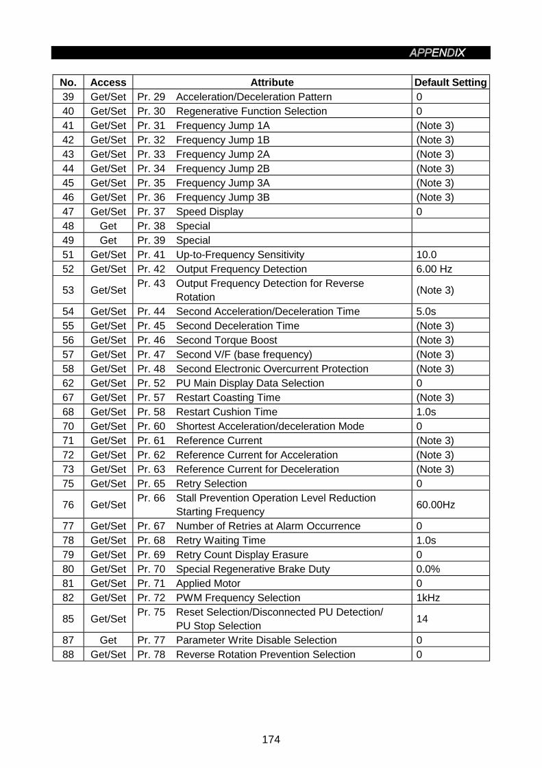
174
No. Access Attribute Default Setting39 Get/Set Pr. 29 Acceleration/Deceleration Pattern 040 Get/Set Pr. 30 Regenerative Function Selection 041 Get/Set Pr. 31 Frequency Jump 1A (Note 3)42 Get/Set Pr. 32 Frequency Jump 1B (Note 3)43 Get/Set Pr. 33 Frequency Jump 2A (Note 3)44 Get/Set Pr. 34 Frequency Jump 2B (Note 3)45 Get/Set Pr. 35 Frequency Jump 3A (Note 3)46 Get/Set Pr. 36 Frequency Jump 3B (Note 3)47 Get/Set Pr. 37 Speed Display 048 Get Pr. 38 Special49 Get Pr. 39 Special51 Get/Set Pr. 41 Up-to-Frequency Sensitivity 10.052 Get/Set Pr. 42 Output Frequency Detection 6.00 Hz
53 Get/SetPr. 43 Output Frequency Detection for Reverse
Rotation(Note 3)
54 Get/Set Pr. 44 Second Acceleration/Deceleration Time 5.0s55 Get/Set Pr. 45 Second Deceleration Time (Note 3)56 Get/Set Pr. 46 Second Torque Boost (Note 3)57 Get/Set Pr. 47 Second V/F (base frequency) (Note 3)58 Get/Set Pr. 48 Second Electronic Overcurrent Protection (Note 3)62 Get/Set Pr. 52 PU Main Display Data Selection 067 Get/Set Pr. 57 Restart Coasting Time (Note 3)68 Get/Set Pr. 58 Restart Cushion Time 1.0s70 Get/Set Pr. 60 Shortest Acceleration/deceleration Mode 071 Get/Set Pr. 61 Reference Current (Note 3)72 Get/Set Pr. 62 Reference Current for Acceleration (Note 3)73 Get/Set Pr. 63 Reference Current for Deceleration (Note 3)75 Get/Set Pr. 65 Retry Selection 0
76 Get/SetPr. 66 Stall Prevention Operation Level Reduction
Starting Frequency60.00Hz
77 Get/Set Pr. 67 Number of Retries at Alarm Occurrence 078 Get/Set Pr. 68 Retry Waiting Time 1.0s79 Get/Set Pr. 69 Retry Count Display Erasure 080 Get/Set Pr. 70 Special Regenerative Brake Duty 0.0%81 Get/Set Pr. 71 Applied Motor 082 Get/Set Pr. 72 PWM Frequency Selection 1kHz
85 Get/SetPr. 75 Reset Selection/Disconnected PU Detection/
PU Stop Selection14
87 Get Pr. 77 Parameter Write Disable Selection 088 Get/Set Pr. 78 Reverse Rotation Prevention Selection 0

175
No. Access Attribute Default Setting89 Get Pr. 79 Operation Mode Selection 290 Get/Set Pr. 80 Motor Capacity (Note 3)92 Get/Set Pr. 82 Motor Exciting Current (Note 3)93 Get/Set Pr. 83 Rated Motor Voltage (Note 2)94 Get/Set Pr. 84 Rated Motor Frequency 60.00Hz95 Get/Set Pr. 85 Special (Note 1)96 Get/Set Pr. 86 Special (Note 1)100 Get/Set Pr. 90 Motor Constant (R1) (Note 3)106 Get/Set Pr. 96 Auto Tuning Setting/Status 0127 Get/Set Pr. 117 Station Number 0128 Get/Set Pr. 118 Communication Speed 192129 Get/Set Pr. 119 Stop Bit Length/Data Length 1130 Get/Set Pr. 120 Parity Check Presence/Absence 2131 Get/Set Pr. 121 Number Of Comms Retries 1132 Get/Set Pr. 122 Communication Check Time Interval 0.0s133 Get/Set Pr. 123 Waiting Time Setting (Note 3)134 Get/Set Pr. 124 CR • LF Presence/Absence Selection 1155 Get/Set Pr. 145 Parameter Unit Language Switching (Note 2)160 Get/Set Pr. 150 Output Current Detection Level 150.0%161 Get/Set Pr. 151 Output Current Detection Period 0.0s162 Get/Set Pr. 152 Zero Current Detection Level 5.0%163 Get/Set Pr. 153 Zero Current Detection Period 0.50s166 Get/Set Pr. 156 Stall Prevention Operation Selection 0170 Get/Set Pr. 160 User Group Read Selection 0178 Get Special (Note 1)179 Get Special (Note 1)181 Get/Set Pr. 171 Actual Operation Hour Meter Clear 0183 Get/Set Pr. 173 User Group 1 Registration 0184 Get/Set Pr. 174 User Group 1 Deletion 0185 Get/Set Pr. 175 User Group 2 Registration 0186 Get/Set Pr. 176 User Group 2 Deletion 0190 Get/Set Pr. 180 (RL) Function Selection 0191 Get/Set Pr. 181 (RM) Function Selection 1192 Get/Set Pr. 182 (RH) Function Selection 2193 Get/Set Pr. 183 MRS Terminal (MRS) Function Selection 6200 Get/Set Pr. 190 (RUN) Function Selection 0201 Get/Set Pr. 191 (FU) Function Selection 4202 Get/Set Pr. 192 ABC Terminal (ABC) Function Selection 99212 Get/Set Pr. 232 Multi-Speed Setting (Speed 8) (Note 3)213 Get/Set Pr. 233 Multi-Speed Setting (Speed 9) (Note 3)
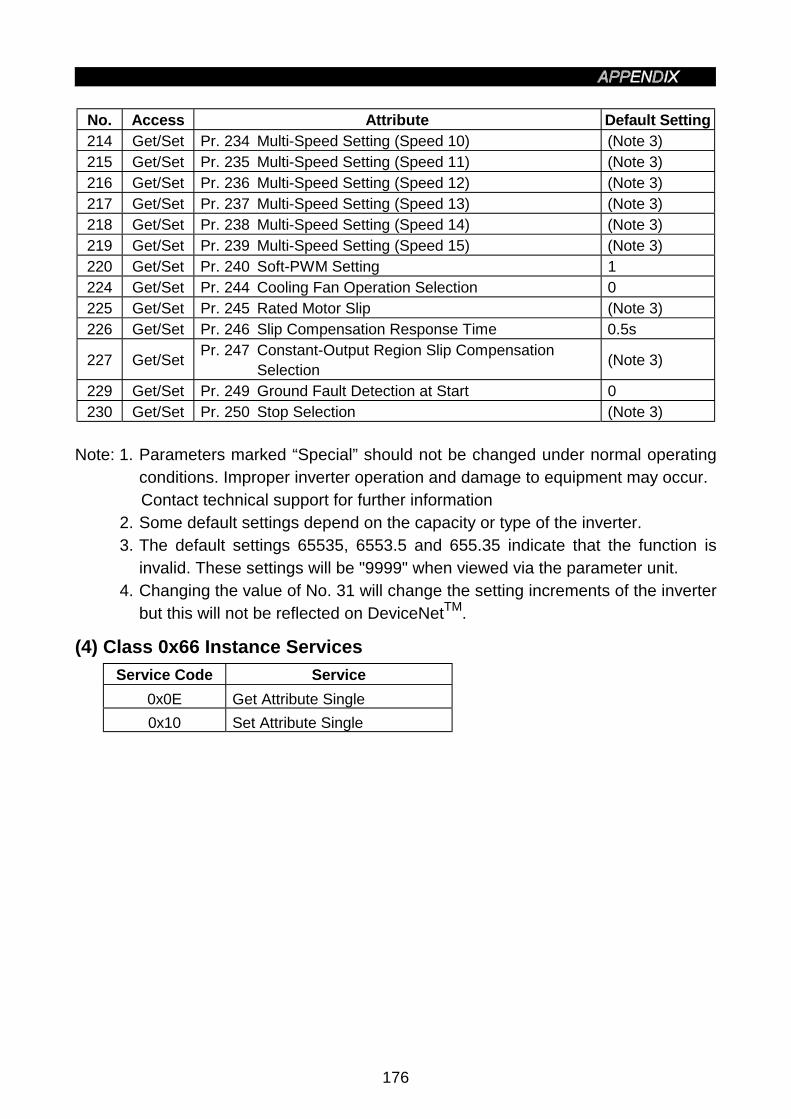
176
No. Access Attribute Default Setting214 Get/Set Pr. 234 Multi-Speed Setting (Speed 10) (Note 3)215 Get/Set Pr. 235 Multi-Speed Setting (Speed 11) (Note 3)216 Get/Set Pr. 236 Multi-Speed Setting (Speed 12) (Note 3)217 Get/Set Pr. 237 Multi-Speed Setting (Speed 13) (Note 3)218 Get/Set Pr. 238 Multi-Speed Setting (Speed 14) (Note 3)219 Get/Set Pr. 239 Multi-Speed Setting (Speed 15) (Note 3)220 Get/Set Pr. 240 Soft-PWM Setting 1224 Get/Set Pr. 244 Cooling Fan Operation Selection 0225 Get/Set Pr. 245 Rated Motor Slip (Note 3)226 Get/Set Pr. 246 Slip Compensation Response Time 0.5s
227 Get/SetPr. 247 Constant-Output Region Slip Compensation
Selection(Note 3)
229 Get/Set Pr. 249 Ground Fault Detection at Start 0230 Get/Set Pr. 250 Stop Selection (Note 3)
Note: 1. Parameters marked “Special” should not be changed under normal operatingconditions. Improper inverter operation and damage to equipment may occur.Contact technical support for further information
2. Some default settings depend on the capacity or type of the inverter.3. The default settings 65535, 6553.5 and 655.35 indicate that the function is
invalid. These settings will be "9999" when viewed via the parameter unit.4. Changing the value of No. 31 will change the setting increments of the inverter
but this will not be reflected on DeviceNetTM.
(4) Class 0x66 Instance Services
Service Code Service
0x0E Get Attribute Single
0x10 Set Attribute Single
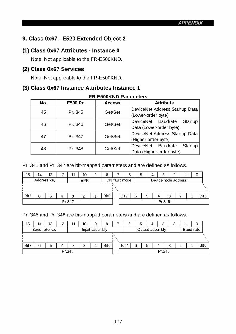
177
9. Class 0x67 - E520 Extended Object 2
(1) Class 0x67 Attributes - Instance 0
Note: Not applicable to the FR-E500KND.
(2) Class 0x67 Services
Note: Not applicable to the FR-E500KND.
(3) Class 0x67 Instance Attributes Instance 1
FR-E500KND ParametersNo. E500 Pr. Access Attribute
45 Pr. 345 Get/SetDeviceNet Address Startup Data(Lower-order byte)
46 Pr. 346 Get/SetDeviceNet Baudrate StartupData (Lower-order byte)
47 Pr. 347 Get/SetDeviceNet Address Startup Data(Higher-order byte)
48 Pr. 348 Get/SetDeviceNet Baudrate StartupData (Higher-order byte)
Pr. 345 and Pr. 347 are bit-mapped parameters and are defined as follows.
15 14 13 12 11 10 9 8 7 6 5 4 3 2 1 0
Bit7 6 5 4 3 2 1 Bit0
Address key
Bit7 6 5 4 3 2 1 Bit0
EPR
Pr.347 Pr.345
Device node addressDN fault mode
Pr. 346 and Pr. 348 are bit-mapped parameters and are defined as follows.
15 14 13 12 11 10 9 8 7 6 5 4 3 2 1 0
Bit7 6 5 4 3 2 1 Bit0
Baud rate key
Bit7 6 5 4 3 2 1 Bit0
Pr.348 Pr.346
Input assembly Output assembly Baud rate

178
Definition of each registration
Name Description DefinitionDefaultSetting
Watch dogtimeoutoperation (WDA)(Note)
DeviceNet connection object(Class code 0x05) instance 2attribute 12
0 = Shift to timeout1 = Automatic deletion2 = Automatic reset
0
DN fault mode
Supports control managementobject (Class code 0x29)instance attribute 16, DN faultmode
0 = Fault + stop1 = Ignore
0
Input assembly
Assemble ID value used forconnection object. (Class code0x05) instance attribute 16,consumed_connection_path
Assemble instance ID0 = 0x46 (70) 4byteMode1 = 0x47 (71) 4byteMode6 = 0xB0 (176) 6byteMode8 = 0x96 (150) 8byteMode
1
Outputassembly
Assemble ID value used forconnection object. (Class code0x05) instance attribute 14,produced_connection_ path
Assemble instance ID0 = 0x14 (20) 4byteMode1 = 0x15 (21) 4byteMode6 = 0x7E (126) 6byteMode8 = 0x64 (100) 8byteMode
1
Baud rateDeviceNet object value (Classcode 0x03 instance attribute 2,baud rate
0 = 125kbps1 = 250kbps2 = 500kbps
0
Device addressDeviceNet object value (Classcode 0x03 instance attribute 1,MAC ID
Node address: range is 0 to 63(Same as attribute definition)
63
Address key Internal confirmation1010 - preset; No otherdefinitions
1010
Baud rate Internal confirmation0101 - preset; No otherdefinitions
0101
Note: The parameter setting will be changed back to the factory setting (0) whenreconnected after a disconnection.
(4) Class 0x67 Instance Services
Service Code Service
0x0E Get Attribute Single
0x10 Set Attribute Single

179
10. Response Timing
Item 1 Polling-Reading and Request Without Changing State:Explicit Messaging (G2 & G3)-Get-Attribute-Reading Data:
Request
Response Time = 1 ms
Response
Item 2. Polling-Writing and Request With Changing State:Explicit Messaging (G2 & G3)-Set-Attribute-Writing Data(Excluding Items 3 & 4):
Request
Response Time = 30 ms
Response
Item 3. PrClr, PrAllClr, PrClr(ECP), PrAllClr(ECP):
Request
Response Time = 5 s
Response
11. Recommendation For Software Developers
For software developers only:a. Make a handshake procedure, send a request, wait for response, then go to next
request.b. Set the waiting time between messages on the basis of the above FR-E500KND
specifications. For example, set 1ms for read and 30ms for write.

APPENDIX 2 Electronic Data Sheets (EDS files)
180
APPENDIX 2 Electronic Data Sheets (EDS files)
The following method is recommended to get the EDS file designed for the FR-E500KND type inverter.
• Download from the Internet.The EDS file can be downloaded at no charge from the Open DeviceNet VenderAssociation, Inc. home page:http://www.odva.org/
Please consult your DeviceNet configuration software instruction manual for the properinstallation of the EDS file.

APPENDIX 3 DeviceNet Parameters
181
APPENDIX 3 DeviceNet Parameters
No. FunctionFR-
E520
KND
EDSCOM
MONObject
Attribute
/service
Attr id/
svc
code
Attr/
svc
name
0 Torque Boost • • E500_66 attrib 10
• • • ACDrive attrib 21HiSpdLimit1 Maximum Frequency
• • E500_66 attrib 11
• • • ACDrive attrib 20LoSpdLimit2 Minimum Frequency
• • E500_66 attrib 12
• • •MotrData/
ACMotrInstattrib 9 Rated f
3 Base Frequency• • E500_66 attrib 13
4Multi-Speed Setting (HighSpeed)
• • E500_66 attrib 14
5Multi-Speed Setting (MiddleSpeed)
• • E500_66 attrib 15
6Multi-Speed Setting (LowSpeed)
• • E500_66 attrib 16
• • • ACDrive attrib 18 Acc t7 Acceleration Time
• • E500_66 attrib 17
• • • ACDrive attrib 19 Dec t8 Deceleration Time
• • E500_66 attrib 189 Electrical Thermal O/L Relay • • E500_66 attrib 19
10DC Injection Brake OperationFrequency
• • E500_66 attrib 20
11DC Injection Brake OperationTime
• • E500_66 attrib 21
12 DC Injection Brake Voltage • • E500_66 attrib 2213 Starting Frequency • • E500_66 attrib 2314 Load Pattern Selection • • E500_66 attrib 24
• • • ACDrive attrib 21HiSpdLimit18
High-Speed MaximumFrequency
• • E500_66 attrib 28
• • •MotrData/ACMotrInst
attrib 7 Rated V19 Base Frequency Voltage
• • E500_66 attrib 29
20Acceleration/DecelerationReference Frequency
• • E500_66 attrib 30
21Acceleration/DecelerationTime Increments
• • E500_66 attrib 31
22Stall Prevention OperationLevel
• • E500_66 attrib 32
23Stall Prevention OperationLevel at Double Speed
• • E500_66 attrib 33
24 Multi-Speed Setting (Speed 4) • • E500_66 attrib 3425 Multi-Speed Setting (Speed 5) • • E500_66 attrib 3526 Multi-Speed Setting (Speed 6) • • E500_66 attrib 3627 Multi-Speed Setting (Speed 7) • • E500_66 attrib 37

182
No. FunctionFR-
E520
KND
EDSCOM
MONObject
Attribute
/service
Attr id/
svc
code
Attr/
svc
name
29Acceleration/DecelerationPattern
• • E500_66 attrib 39
30Regenerative FunctionSelection
• • E500_66 attrib 40
31 Frequency Jump 1A • • E500_66 attrib 4132 Frequency Jump 1B • • E500_66 attrib 4233 Frequency Jump 2A • • E500_66 attrib 4334 Frequency Jump 2B • • E500_66 attrib 4435 Frequency Jump 3A • • E500_66 attrib 4536 Frequency Jump 3B • • E500_66 attrib 4637 Speed Display • • E500_66 attrib 4741 Up-to-Frequency Sensitivity • • E500_66 attrib 5142 Output Frequency Detection • • E500_66 attrib 52
43Output Frequency Detectionfor Reverse Rotation
• • E500_66 attrib 54
44Second Acceleration/Deceleration Time
• • E500_66 attrib 54
45 Second Deceleration Time • • E500_66 attrib 5546 Second Torque Boost • • E500_66 attrib 5647 Second V/F (base frequency) • • E500_66 attrib 57
48Second Electronic OvercurrentProtection
• • E500_66 attrib 60
52PU Main Display DataSelection
• • E500_66 attrib 62
57 Restart Coasting Time • • E500_66 attrib 6758 Restart Cushion Time • • E500_66 attrib 68
60Shortest Acceleration/deceleration Mode
• • E500_66 attrib 70
61 Reference Current • • E500_66 attrib 71
62Reference Current forAcceleration
• • E500_66 attrib 72
63Reference Current forDeceleration
• • E500_66 attrib 73
65 Retry Selection • • E500_66 attrib 75
66Stall Prevention OperationLevel Reduction StartingFrequency
• • E500_66 attrib 76
67Number of Retries at AlarmOccurrence
• • E500_66 attrib 77
68 Retry Waiting Time • • E500_66 attrib 7869 Retry Count Display Erasure • • E500_66 attrib 79
70Special Regenerative BrakeDuty
• • E500_66 attrib 80
71 Applied Motor • • E500_66 attrib 8172 PWM Frequency Selection • • E500_66 attrib 82
75Reset Selection/PUDisconnection Detection
• • E500_66 attrib 85
77Parameter Write DisableSelection
• • E500_66 attrib 87
78Reverse Rotation PreventionSelection
• • E500_66 attrib 88
79 Operation Mode Selection • • E500_66 attrib 89

183
No. FunctionFR-
E520
KND
EDSCOM
MONObject
Attribute
/service
Attr id/
svc
code
Attr/
svc
name
80 Motor Capacity • • E500_66 attrib 9082 Motor Exciting Current • • E500_66 attrib 92
• • •MotrData/ACMotrInst
attrib 7 Rated V83 Rated Motor Voltage
• • E500_66 attrib 93
• • •MotrData/ACMotrInst
attrib 9 Rated f84 Rated Motor Frequency
• • E500_66 attrib 9490 Motor Constant (R1) • • E500_66 attrib 10096 Auto Tuning Setting/Status • • E500_66 attrib 106117 Station Number • • E500_66 attrib 127118 Communication Speed • • E500_66 attrib 128119 Stop Bit Length/Data Length • • E500_66 attrib 129
120Parity CheckPresence/Absence
• • E500_66 attrib 130
121Number Of CommunicationRetries
• • E500_66 attrib 131
122Communication Check TimeInterval
• • E500_66 attrib 132
123 Waiting Time Setting • • E500_66 attrib 133
124CR, LF Presence/AbsenceSelection
• • E500_66 attrib 134
150 Output Current Detection Level • • E500_66 attrib 160
151Output Current DetectionPeriod
• • E500_66 attrib 161
152 Zero Current Detection Level • • E500_66 attrib 162153 Zero Current Detection Period • • E500_66 attrib 163
156Stall Prevention OperatingSelection
• • E500_66 attrib 166
168 Reserved • • E500_66 attrib 178169 Reserved • • E500_66 attrib 179160 User Group Read Selection • • E500_66 attrib 170
171Actual Operation Hour MeterClear
• • E500_66 attrib 181
173 User Group 1 Registration • • E500_66 attrib 183174 User Group 1 Deletion • • E500_66 attrib 184175 User Group 2 Registration • • E500_66 attrib 185176 User Group 2 Deletion • • E500_66 attrib 186180 (RL) Function Selection • • E500_66 attrib 190181 (RM) Function Selection • • E500_66 attrib 191182 (RH) Function Selection • • E500_66 attrib 192
183MRS Terminal (MRS) FunctionSelection
• • E500_66 attrib 193
190 (RUN) Function Selection • • E500_66 attrib 200191 (FU) Function Selection • • E500_66 attrib 201
192A, B, C Terminal (ABC)Function Selection
• • E500_66 attrib 202
232 Multi-Speed Setting (Speed 8) • • E500_66 attrib 212233 Multi-Speed Setting (Speed 9) • • E500_66 attrib 213234 Multi-Speed Setting (Speed 10) • • E500_66 attrib 214235 Multi-Speed Setting (Speed 11) • • E500_66 attrib 215

184
No. FunctionFR-
E520
KND
EDSCOM
MONObject
Attribute
/service
Attr id/
svc
code
Attr/
svc
name
236 Multi-Speed Setting (Speed 12) • • E500_66 attrib 216237 Multi-Speed Setting (Speed 13) • • E500_66 attrib 217238 Multi-Speed Setting (Speed 14) • • E500_66 attrib 218239 Multi-Speed Setting (Speed 15) • • E500_66 attrib 219240 Soft-PWM Selection • • E500_66 attrib 220250 Stop Selection • • E500_66 attrib 230
345DeviceNet Address StartupData (Lower byte)
• • E500_67 attrib 45
346DeviceNet Baudrate StartupData (Lower byte)
• • E500_67 attrib 46
347DeviceNet Address StartupData (Higher byte)
• • E500_67 attrib 47
348DeviceNet Baudrate StartupData (Higher byte)
• • E500_67 attrib 48
Inverter Reset • • ACDrive attrib 101Parameter Clear • • ACDrive attrib 102Parameter All Clear • • ACDrive attrib 103Parameter Clear (Ex Com Pr) • • ACDrive attrib 105Parameter All Clear (Ex ComPr)
• • ACDrive attrib 106
Running Frequency (RAM) • • ACDrive attrib 112
Running Frequency (E2PROM) • • ACDrive attrib 113Inverter Status/Control InputCmd
• • ACDrive attrib 114
Op Mode/InverterConfiguration
• • ACDrive attrib 120
Alarm History 1/Alarm History All Clear
• • ACDrive attrib 141

APPENDIX 4 Data Code List
185
APPENDIX 4 Data Code List
Data CodeFunc-tion
ParameterNumber Name
Read Write
Link Parameter ExtensionSetting
(Data Code 7F/FF)0 Torque boost 00 80 0
1 Maximum frequency 01 81 0
2 Minimum frequency 02 82 0
3 Base frequency 03 83 0
4 Multi-speed setting (high speed) 04 84 0
5 Multi-speed setting (middle speed) 05 85 0
6 Multi-speed setting (low speed) 06 86 0
7 Acceleration time 07 87 0
8 Deceleration time 08 88 0
Bas
ic f
unct
ions
9 Electronic thermal O/L relay 09 89 0
10DC injection brake operationfrequency
0A 8A 0
11 DC injection brake operation time 0B 8B 0
12 DC injection brake voltage 0C 8C 0
13 Starting frequency 0D 8D 0
14 Load pattern selection 0E 8E 0
18 High-speed maximum frequency 12 92 0
19 Base frequency voltage 13 93 0
20 Acceleration/deceleration referencefrequency 14 94 0
21 Acceleration/deceleration timeincrements 15 95 0
22 Stall prevention operation level 16 96 0
23 Stall prevention operation levelcompensation factor at double speed 17 97 0
24 Multi-speed setting (speed 4) 18 98 0
25 Multi-speed setting (speed 5) 19 99 0
26 Multi-speed setting (speed 6) 1A 9A 0
27 Multi-speed setting (speed 7) 1B 9B 0
29 Acceleration/deceleration pattern 1D 9D 0
30 Regenerative function selection 1E 9E 0
31 Frequency jump 1A 1F 9F 0
32 Frequency jump 1B 20 A0 0
33 Frequency jump 2A 21 A1 0
34 Frequency jump 2B 22 A2 0
35 Frequency jump 3A 23 A3 0
36 Frequency jump 3B 24 A4 0
37 Speed display 25 A5 0
38 Frequency at 5V (10V) input 26 A6 0
Sta
ndar
d op
erat
ion
func
tions
39 Frequency at 20mA input 27 A7 0

186
Data CodeFunc-tion
ParameterNumber Name
Read Write
Link Parameter ExtensionSetting
(Data Code 7F/FF)41 Up-to-frequency sensitivity 29 A9 0
42 Output frequency detection 2A AA 0
Out
put
term
inal
func
tions
43 Output frequency detection forreverse rotation 2B AB 0
44 Second acceleration/decelerationtime 2C AC 0
45 Second deceleration time 2D AD 0
46 Second torque boost 2E AE 0
47 Second V/F (base frequency) 2F AF 0
Se
con
d f
un
ctio
ns
48 Second electronic overcurrentprotection 30 B0 0
Dis
pla
yfu
nct
ion
s
52 PU main display data selection 34 B4 0
57 Restart coasting time 39 B9 0
Aut
omat
icre
star
tfu
nctio
ns
58 Restart cushion time 3A BA 0
60Shortest acceleration/decelerationmode
3C BC 0
61 Reference I for intelligent mode 3D BD 0
62 Ref. I for intelligent mode accel 3E BE 0
63 Ref. I for intelligent mode decel 3F BF 0
65 Retry selection 41 C1 0
66Stall prevention operation levelreduction starting frequency
42 C2 0
67 Number of retries at alarmoccurrence 43 C3 0
68 Retry waiting time 44 C4 0
69 Retry count display erasure 45 C5 0
70 Special regenerative brake duty 46 C6 0
71 Applied motor 47 C7 0
72 PWM frequency selection 48 C8 0
75Reset selection/disconnected PUdetection/PU stop selection
4B CB 0
77 Parameter write disable selection 4D CD 0
78 Reverse rotation preventionselection 4E CE 0
Op
era
tion
se
lect
ion
fu
nct
ion
s
79 Operation mode selection 4F CF 0
80 Motor capacity 50 D0 0
82 Motor exciting current 52 D2 0
83 Rated motor voltage 53 D3 0
84 Rated motor frequency 54 D4 0
90 Motor constant (R1) 5A DA 0
Mo
tor
con
sta
nts
96 Auto-tuning setting/status 60 E0 0

187
Data CodeFunc-tion
ParameterNumber Name
Read Write
Link Parameter ExtensionSetting
(Data Code 7F/FF)117 Station number 11 91 1118 Communication speed 12 92 1119 Stop bit length 13 93 1120 Parity check presence/absence 14 94 1121 Number of communication retries 15 95 1
122 Communication check timeinterval
16 96 1
123 Waiting time setting 17 97 1Co
mm
un
ica
tion
fun
ctio
ns
124 CR • LF presence/absenceselection
18 98 1
Add
ition
alfu
nctio
n
145 Parameter unit language selection 2D AD 1
150 Output current detection level 32 B2 1
151 Output current detection period 33 B3 1
152 Zero current detection level 34 B4 1
Cu
rre
nt
de
tect
ion
153 Zero current detection period 35 B5 1
Su
bfu
nct
ion
156Stall prevention operationselection 38 B8 1
Ad
diti
on
al
fun
ctio
n
160 User group read selection 00 80 2
Initi
al
mo
nito
r
171 Actual operation hour meter clear 0B 8B 2
173 User group 1 registration 0D 8D 2
174 User group 1 deletion 0E 8E 2
175 User group 2 registration 0F 8F 2Use
rfu
nct
ion
s
176 User group 2 deletion 10 90 2
168
Spe
cial
169Parameters set by manufacturer. Do not set.
180 (RL) function selection 14 94 2
181 (RM) function selection 15 95 2
182 (RH) function selection 16 96 2
183 MRS terminal (MRS) functionselection
17 97 2
190 (RUN) function selection 1E 9E 2
191 (FU) function selection 1F 9F 2Ter
min
al (
Dev
iceN
et I
/O)
assi
gnm
ent
func
tions
192 A, B, C terminal (ABC) functionselection
20 A0 2

188
Data CodeFunc-tion
ParameterNumber Name
Read Write
Link Parameter ExtensionSetting
(Data Code 7F/FF)
232 Multi-speed setting (speed 8) 28 A8 2
233 Multi-speed setting (speed 9) 29 A9 2
234 Multi-speed setting (speed 10) 2A AA 2
235 Multi-speed setting (speed 11) 2B AB 2
236 Multi-speed setting (speed 12) 2C AC 2
237 Multi-speed setting (speed 13) 2D AD 2
238 Multi-speed setting (speed 14) 2E AE 2
Mu
lti-s
pe
ed
op
era
tion
239 Multi-speed setting (speed 15) 2F AF 2
240 Soft-PWM setting 30 B0 2
244 Cooling fan operation selection 34 B4 2
245 Rated motor slip 35 B5 2
246 Slip compensation response time 36 B6 2
247 Constant-output region slipcompensation selection
37 B7 2
Su
b f
un
ctio
ns
249 Ground fault detection at start 39 B9 2
Sto
pse
lect
ion
func
tion
250 Stop selection 3A BA 2
345DeviceNet Address Startup Data(Lower byte) 2D AD 3
346DeviceNet Baudrate Startup Data(Lower byte) 2E AE 3
347DeviceNet Address Startup Data(Higher byte) 2F AF 3
De
vice
Ne
tfu
nct
ion
s
348DeviceNet Baudrate Startup Data(Higher byte) 30 B0 3
990 Buzzer control 5A DA 9
Dis
pla
y
991 LCD contrast (FR-PU04) 5B DB 9

REVISIONS*The manual number is given on the bottom left of the back cover.
Print Date *Manual Number Revision
Jul., 1998 IB(NA)-0600008-A First edition
Nov., 2000 IB(NA)-0600008-B Revision of specifications
Mar., 2001 IB(NA)-0600008-C Partial change
Specification changes made with the receipt of ODVAconformance test version A13 certification