FPGAs and IRRADIATED FPGAs for the LHCb UPGRADE Bin Gui, Ray Mountain.
11
FPGAs and IRRADIATED FPGAs for the LHCb UPGRADE Bin Gui, Ray Mountain
-
date post
20-Dec-2015 -
Category
Documents
-
view
234 -
download
1
Transcript of FPGAs and IRRADIATED FPGAs for the LHCb UPGRADE Bin Gui, Ray Mountain.

FPGAs and IRRADIATED FPGAs for the LHCb
UPGRADE
Bin Gui, Ray Mountain

Communication
Communication Data line
Sending 8-bit pattern to FPGA through TNG-5, then the data being shifted out and back to the PC.
Since we are using LabView to control and generate the data, the frequency is just 32Hz.
Control lineTo check the FPGA’s status and get response from it.

Hardware
Transition Board
TNG-5
FPGA
Power Supply forTransition Board
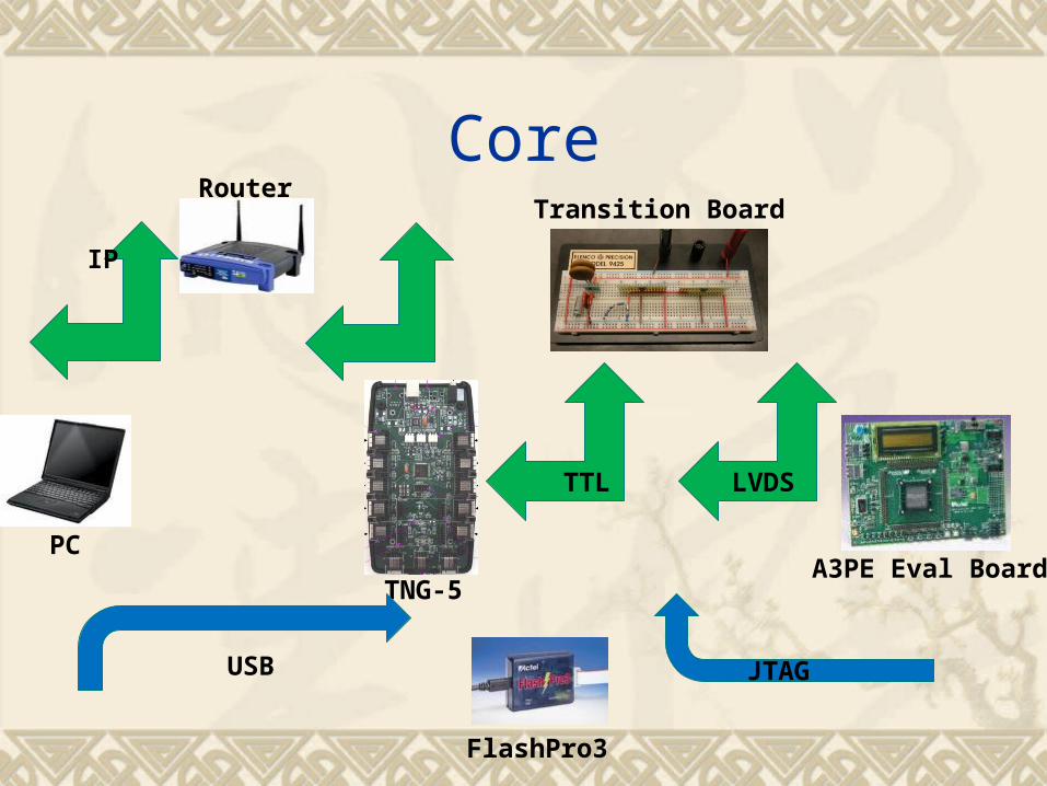
Core
TTL LVDS
TNG-5A3PE Eval Board
Transition Board
PC
Router
IP
JTAGUSB
FlashPro3

Handshaking
To found the communication between FPGA and PC, it includes three parts: Control program (LabView) Hardware (Mapping the ports, connect all
devices, etc) Firmware (Configuring FPGA)

Control Program (Front Panel)
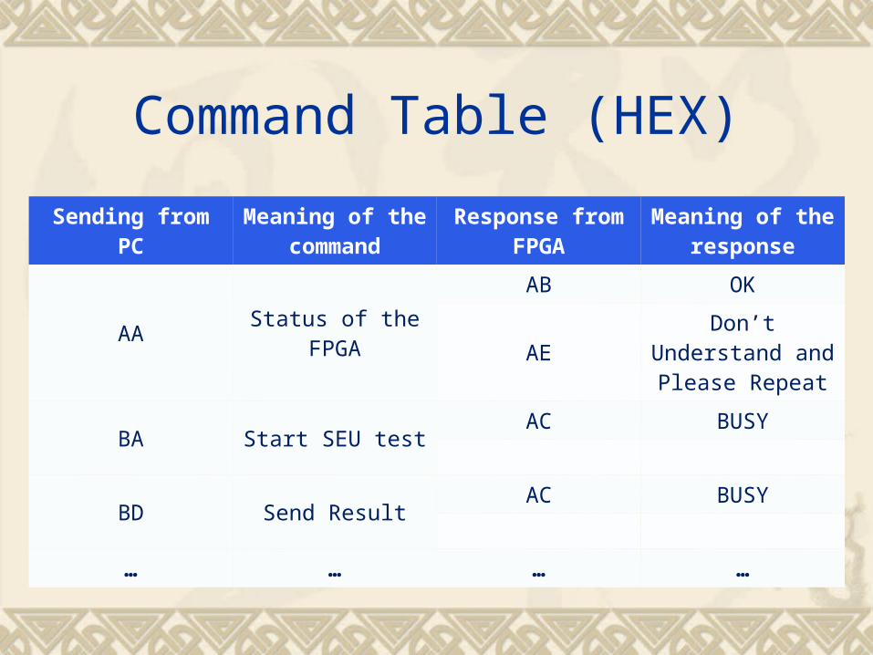
Command Table (HEX)
Sending from PCMeaning of the
commandResponse from
FPGAMeaning of the
response
AAStatus of the
FPGA
AB OK
AEDon’t Understand
and Please Repeat
BA Start SEU testAC BUSY
BD Send ResultAC BUSY
… … … …

Firmware (FPGA configuration)
Not finish, need to be modified.
1 2 3
4
4
56
7

To do list
Finish the work of communication between FPGA and PC.
Soldering transition board. Memory, static register, etc. SEU test Irradiation test

Backup - PLL
200MHz (by PLL) 350MHz (by PLL)
40MHz (oscillator on the board)
The clock is LVTTL signal, but observing from the waveform,
the amplitude varies a lot.?

BackupColor Convention on CAT 5E Primary
Color of the line of the connector
Pin number on Transition
Board
Port on Transition
BoardPort on FPGA
Pin number on FPGA
Orange Receiver 2 R1+ TX1+ 7
Blue Receiver 1 R1- TX1- 8
Green Receiver 6 R2+ TX2+ 9
Red Receiver 7 R2- TX2- 10
Black Driver 2 D1+ RX1+ 11
Yellow Driver 3 D1- RX1- 12
Brown Driver 6 D2+ RX2+ 13
White Driver 5 D2- RX2- 14
**‘+‘ refers to positive signal of the transmit/ receive side of balanced signal Transmission.**‘-‘ refers to negative signal of the transmit/ receive side of balanced signal Transmission