FPA‑5000 With Functional Modules...Fire Alarm Systems | FPA‑5000 With Functional Modules...
7
Fire Alarm Systems | FPA‑5000 With Functional Modules FPA‑5000 With Functional Modules www.boschsecurity.com u Modular configuration allowing for easy extension u Interconnection of up to 32 Panel Controllers, Remote Keypads, and OPC servers u Multiple CAN loop connection with high- performance Ethernet backbone and redundancy u Installation and auto-detection of functional modules by simply plugging them into the panel rail u Connection to BIS Building Integration System via OPC server Thanks to the modular configuration, the innovative FPA‑5000 Modular Fire Panel easily adapts to local circumstances and regulations. Due to the different functional modules, country-specific characteristics are accommodated in the connection just as quickly as the respective alarm handling. The fire panel is available with two different housings: • Housing for mounting directly on the wall • Frame installation housings which are fitted to the mounting frame and can be swiveled. With the aid of special mounting kits, the housings can be mounted in 482.6 mm (19") cabinets. All housings can be extended with various additional housings for all conceivable applications. The FMR‑5000 Remote Keypad offers the decentralized operation of a control panel or control panel network. Thanks to the external CAN and Ethernet interfaces, several Panel Controllers and Remote Keypads can be interconnected. Using either a single‑loop structure or multiple‑loop structures with Ethernet backbone, the network can be adapted to nearly every application conditions. Ethernet CAN 1 2 CAN CAN CAN/Ethernet Network 1 Fire panel 2 Remote Keypad Additionally, the Ethernet interface allows for the connection to a Building Management System (BIS Bosch Building Integration System) via an OPC server. FPA‑5000 systems can be connected to the Bosch UGM 2040 Universal Security System and thus, be integrated into a large network system.
Transcript of FPA‑5000 With Functional Modules...Fire Alarm Systems | FPA‑5000 With Functional Modules...
Fire Alarm Systems | FPA‑5000 With Functional Modules
FPA‑5000 With Functional Modules
www.boschsecurity.com
u Modular configuration allowing for easy extension
u Interconnection of up to 32 Panel Controllers,Remote Keypads, and OPC servers
u Multiple CAN loop connection with high-performance Ethernet backbone and redundancy
u Installation and auto-detection of functionalmodules by simply plugging them into the panel rail
u Connection to BIS Building Integration System viaOPC server
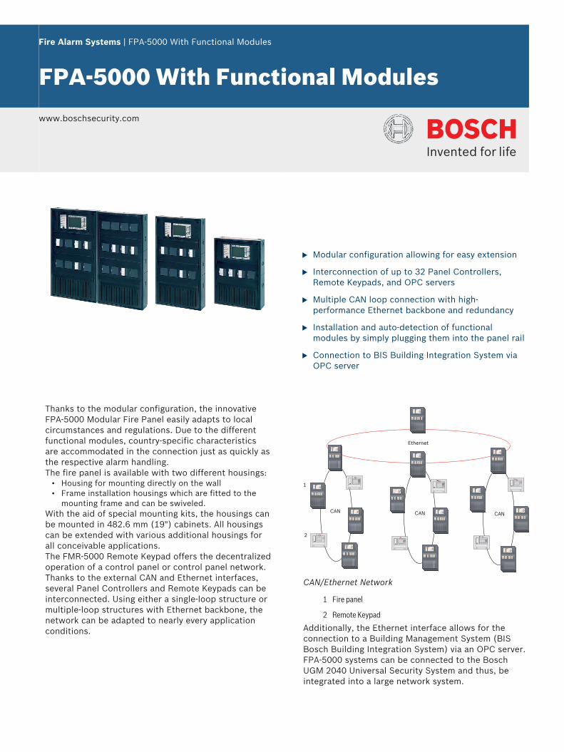
Thanks to the modular configuration, the innovativeFPA‑5000 Modular Fire Panel easily adapts to localcircumstances and regulations. Due to the differentfunctional modules, country-specific characteristicsare accommodated in the connection just as quickly asthe respective alarm handling.The fire panel is available with two different housings:
• Housing for mounting directly on the wall• Frame installation housings which are fitted to the
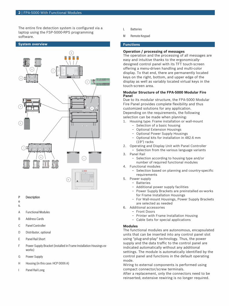
mounting frame and can be swiveled.With the aid of special mounting kits, the housings canbe mounted in 482.6 mm (19") cabinets. All housingscan be extended with various additional housings forall conceivable applications.The FMR‑5000 Remote Keypad offers the decentralizedoperation of a control panel or control panel network.Thanks to the external CAN and Ethernet interfaces,several Panel Controllers and Remote Keypads can beinterconnected. Using either a single‑loop structure ormultiple‑loop structures with Ethernet backbone, thenetwork can be adapted to nearly every applicationconditions.
Ethernet
CAN
1
2
CAN CAN
CAN/Ethernet Network
1 Fire panel
2 Remote Keypad
Additionally, the Ethernet interface allows for theconnection to a Building Management System (BISBosch Building Integration System) via an OPC server.FPA‑5000 systems can be connected to the BoschUGM 2040 Universal Security System and thus, beintegrated into a large network system.
The entire fire detection system is configured via alaptop using the FSP-5000-RPS programmingsoftware.
System overview
NI
TUO
NI
TUO
#0*
8 9
5 6
2 3
7
4
1
?
PQRS TUV WXYZ
GHI JKI MNO
ABC DEF
F ire
Test
City Tie
City Tie Fault
Ground Fault
Battery Fault
Power
Trouble
Signal Silence
Bypassed
Supervisory
NETZEINNETZSTROMStörungBATTERIE1StörungBATTERIE2Störung
FAULTMAIN
+-BAT1+-
BAT2+-
BAT1+- +-FAULT ACFAULT
AUX3+- AUX4+-AUX2+-AUX1+- AUX5+- AUX6+-
BCM0000A
LS
N 0
30
0 A
AU X 1+ -
L S N 1a -b +
AU X 2+ -
L S N 2a -b +
ZONE4
Störung
ZONE3
Störung
ZONE2
Störung
ZONE1
Störung
CZM000
4A
AUX1+ -
OUT1+-
IN1+-
AUX2+ -
OUT2+-
IN2+-
AUX3+ -
OUT3+-
IN3+-
AUX4+ -
OUT4+-
IN4+-
ANI00
16A
F2F1
NC1
NO1
C1 NC2
NO2
C2
FB1+ -
FB2+ -
RELAIS2
Störung
RELAIS1
Störung
RMH0
002A
OUT3
OUT2
OUT4
OUT6
OUT5
OUT7
GND
OUT8
GND
GND
GND
IN1 IN3IN2 IN4 IN6IN5 IN7 GNDIN8 GND
GND
GND
OUT1
IOP0008A
C
D
H
L
M
B
E
F
G
I
A
A
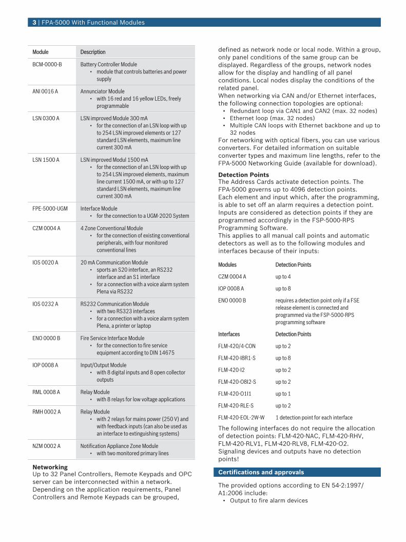
Pos.
Description
A Functional Modules
B Address Cards
C Panel Controller
D Distributor, optional
E Panel Rail Short
F Power Supply Bracket (installed in Frame Installation Housings ex-works)
G Power Supply
H Housing (in this case: HCP 0006 A)
I Panel Rail Long
L Batteries
M Remote Keypad
Functions
Operation / processing of messagesThe operation and the processing of all messages areeasy and intuitive thanks to the ergonomically-designed control panel with its TFT touch‑screenoffering a menu-driven handling and multi-colordisplay. To that end, there are permanently locatedkeys on the right, bottom, and upper edge of thedisplay as well as variably located virtual keys in thetouch-screen area.
Modular Structure of the FPA‑5000 Modular FirePanelDue to its modular structure, the FPA‑5000 ModularFire Panel provides complete flexibility and thuscustomized solutions for any application.Depending on the requirements, the followingselection can be made when planning:1. Housing type: Frame installation or wall-mount
– Selection of a basic housing– Optional Extension Housings– Optional Power Supply Housings– Optional kits for installation in 482.6 mm
(19") racks2. Operating and Display Unit with Panel Controller
– Selection from the various language variants3. Panel Rail
– Selection according to housing type and/ornumber of required functional modules
4. Functional modules– Selection based on planning and country-specific
requirements5. Power supply
– Batteries– Additional power supply facilities– Power Supply Brackets are preinstalled ex-works
for Frame Installation Housings– For Wall-mount Housings, Power Supply Brackets
are selected as needed6. Additional accessories
– Front Doors– Printer with Frame Installation Housing– Cable Sets for special applications
ModulesThe functional modules are autonomous, encapsulatedunits that can be inserted into any control panel slotusing "plug-and-play" technology. Thus, the powersupply and the data traffic to the control panel areindicated automatically without any additionalsettings. The module is automatically identified by thecontrol panel and functions in the default operatingmode.Wiring to external components is performed usingcompact connector/screw terminals.After a replacement, only the connectors need to bereinserted; extensive rewiring is no longer required.
2 | FPA‑5000 With Functional Modules
Module Description
BCM‑0000‑B Battery Controller Module• module that controls batteries and power
supply
ANI 0016 A Annunciator Module• with 16 red and 16 yellow LEDs, freely
programmable
LSN 0300 A LSN improved Module 300 mA• for the connection of an LSN loop with up
to 254 LSN improved elements or 127standard LSN elements, maximum linecurrent 300 mA
LSN 1500 A LSN improved Modul 1500 mA• for the connection of an LSN loop with up
to 254 LSN improved elements, maximumline current 1500 mA, or with up to 127standard LSN elements, maximum linecurrent 300 mA
FPE‑5000‑UGM Interface Module• for the connection to a UGM‑2020 System
CZM 0004 A 4 Zone Conventional Module• for the connection of existing conventional
peripherals, with four monitoredconventional lines
IOS 0020 A 20 mA Communication Module• sports an S20 interface, an RS232
interface and an S1 interface• for a connection with a voice alarm system
Plena via RS232
IOS 0232 A RS232 Communication Module• with two RS323 interfaces• for a connection with a voice alarm system
Plena, a printer or laptop
ENO 0000 B Fire Service Interface Module• for the connection to fire service
equipment according to DIN 14675
IOP 0008 A Input/Output Module• with 8 digital inputs and 8 open collector
outputs
RML 0008 A Relay Module• with 8 relays for low voltage applications
RMH 0002 A Relay Module• with 2 relays for mains power (250 V) and
with feedback inputs (can also be used asan interface to extinguishing systems)
NZM 0002 A Notification Appliance Zone Module• with two monitored primary lines
NetworkingUp to 32 Panel Controllers, Remote Keypads and OPCserver can be interconnected within a network.Depending on the application requirements, PanelControllers and Remote Keypads can be grouped,
defined as network node or local node. Within a group,only panel conditions of the same group can bedisplayed. Regardless of the groups, network nodesallow for the display and handling of all panelconditions. Local nodes display the conditions of therelated panel.When networking via CAN and/or Ethernet interfaces,the following connection topologies are optional:
• Redundant loop via CAN1 and CAN2 (max. 32 nodes)• Ethernet loop (max. 32 nodes)• Multiple CAN loops with Ethernet backbone and up to
32 nodesFor networking with optical fibers, you can use variousconverters. For detailed information on suitableconverter types and maximum line lengths, refer to theFPA-5000 Networking Guide (available for download).
Detection PointsThe Address Cards activate detection points. TheFPA‑5000 governs up to 4096 detection points.Each element and input which, after the programming,is able to set off an alarm requires a detection point.Inputs are considered as detection points if they areprogrammed accordingly in the FSP‑5000‑RPSProgramming Software.This applies to all manual call points and automaticdetectors as well as to the following modules andinterfaces because of their inputs:
Modules Detection Points
CZM 0004 A up to 4
IOP 0008 A up to 8
ENO 0000 B requires a detection point only if a FSErelease element is connected andprogrammed via the FSP-5000-RPSprogramming software
Interfaces Detection Points
FLM-420/4-CON up to 2
FLM-420-I8R1-S up to 8
FLM-420-I2 up to 2
FLM-420-O8I2-S up to 2
FLM-420-O1I1 up to 1
FLM-420-RLE-S up to 2
FLM-420-EOL-2W-W 1 detection point for each interface
The following interfaces do not require the allocationof detection points: FLM‑420‑NAC, FLM‑420‑RHV,FLM‑420‑RLV1, FLM‑420‑RLV8, FLM‑420‑O2.Signaling devices and outputs have no detectionpoints!
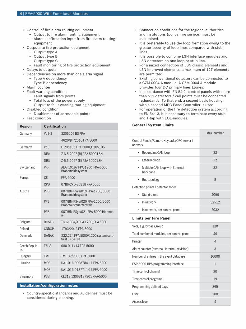
Certifications and approvals
The provided options according to EN 54‑2:1997/A1:2006 include:
• Output to fire alarm devices
3 | FPA‑5000 With Functional Modules
• Control of fire alarm routing equipment– Output to fire alarm routing equipment– Alarm confirmation input from fire alarm routing
equipment• Outputs to fire protection equipment
– Output type A– Output type B– Output type C– Fault monitoring of fire protection equipment
• Delays to outputs• Dependencies on more than one alarm signal
– Type A dependency– Type B dependency
• Alarm counter• Fault warning condition
– Fault signals from points– Total loss of the power supply– Output to fault warning routing equipment
• Disabled condition– Disablement of adressable points
• Test condition
Region Certification
Germany VdS-S S205106 BS FPA
4620/DT/2010 FPA-5000
Germany VdS G 205106 FPA-5000_G205106
DIBt Z-6.5-2027 (B) FSA 5000 LSN
DIBt Z-6.5-2027 (E) FSA 5000 LSN
Switzerland VKF AEAI 19197 FPA-1200_FPA-5000Brandmeldesystem
Europe CE FPA-5000
CPD 0786-CPD-20818 FPA 5000
Austria PFB 007/BM-PSys/019 FPA-1200/5000Brandmeldesystem
PFB 007/BM-PSys/020 FPA-1200/5000Brandfallsteuerzentrale
PFB 007/BM-PSys/021 FPA-5000 Hierarch-ie
Belgium BOSEC TCC2-894/a FPA 1200_FPA 5000
Poland CNBOP 1793/2013 FPA-5000
Denmark DANAK 232.234 FPA 5000/1200 system certi-fikat EN54-13
Czech Repub-lic
TZÚS 080-011414 FPA-5000
Hungary TMT TMT-32/2005 FPA-5000
Ukraine MOE UA1.016.0008784-11 FPA-5000
MOE UA1.016.0137711-13 FPA-5000
Singapore PSB CLS1B 13068137901 FPA-5000
Installation/configuration notes
• Country-specific standards and guidelines must beconsidered during planning.
• Connection conditions for the regional authoritiesand institutions (police, fire service) must bemaintained.
• It is preferable to use the loop formation owing to thegreater security of loop lines compared with stublines.
• It is possible to combine LSN interface modules andLSN detectors on one loop or stub line.
• For a mixed connection of LSN classic elements andLSN improved elements, a maximum of 127 elementsare permitted.
• Existing conventional detectors can be connected toa CZM 0004 A module. A CZM 0004 A moduleprovides four DC primary lines (zones).
• In accordance with EN 54‑2, control panels with morethan 512 detectors / call points must be connectedredundantly. To that end, a second basic housingwith a second MPC Panel Controller is used.
• For operation of the fire detection system accordingto EN 54‑13, it is necessary to terminate every stuband T-tap with EOL-modules.
General System Limits
Max. number
Control Panels/Remote Keypads/OPC server innetwork
• Redundant CAN loop 32
• Ethernet loop 32
• Multiple CAN loop with Ethernetbackbone
32
• Bus topology 8
Detection points / detector zones
• Stand-alone 4096
• In network 32512
• In network, per control panel 2032
Limits per Fire Panel
Sets, e.g. bypass group 128
Total number of modules, per control panel 46
Printer 4
Alarm counter (external, internal, revision) 3
Number of entries in the event database 10000
FSP-5000-RPS programming interface 1
Time control channel 20
Time control programs 19
Programming defined days 365
User 200
Access level 4
4 | FPA‑5000 With Functional Modules
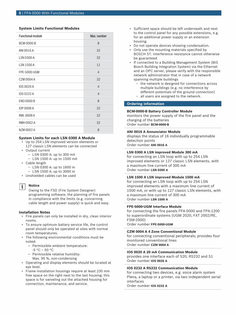
System Limits Functional Modules
Functional module Max. number
BCM-0000-B 8
ANI 0016 A 32
LSN 0300 A 32
LSN 1500 A 11
FPE-5000-UGM 4
CZM 0004 A 32
IOS 0020 A 4
IOS 0232 A 4
ENO 0000 B 8
IOP 0008 A 32
RML 0008 A 32
RMH 0002 A 32
NZM 0002 A 8
System Limits for each LSN 0300 A Module• Up to 254 LSN improved version elements or
127 classic LSN elements can be connected• Output current
– LSN 0300 A: up to 300 mA– LSN 1500 A: up to 1500 mA
• Cable length– LSN 0300 A: up to 1600 m– LSN 1500 A: up to 3000 m
• Unshielded cables can be used
NoticeOwing to the FSD (Fire System Designer)programming software, the planning of fire panelsin compliance with the limits (e.g. concerningcable length and power supply) is quick and easy.
Installation Notes• Fire panels can only be installed in dry, clean interior
rooms.• To ensure optimum battery service life, the control
panel should only be operated at sites with normalroom temperatures.
• The following environmental conditions must benoted:
– Permissible ambient temperature: -5 °C – 50 °C
– Permissible relative humidity: Max. 95 %, non-condensing
• Operating and display elements should be located ateye level.
• Frame installation housings require at least 230 mmfree space on the right next to the last housing; thisspace is for swiveling out the attached housing forconnection, maintenance, and service.
• Sufficient space should be left underneath and nextto the control panel for any possible extensions, e.g.for an additional power supply or an extensionhousing.
• Do not operate devices showing condensation.• Only use the mounting materials specified by
BOSCH ST. Interference resistance cannot otherwisebe guaranteed.
• If connected to a Building Management System (BISBosch Building Integration System) via the Ethernetand an OPC server, please verify with the responsiblenetwork administrator that in case of a networkspanning multiple buildings
– the network is designed for connections acrossmultiple buildings (e.g. no interference bydifferent potentials of the ground connection)
– all users are assigned to the network.
Ordering information
BCM‑0000‑B Battery Controller Modulemonitors the power supply of the fire panel and thecharging of the batteriesOrder number BCM-0000-B
ANI 0016 A Annunciator Moduledisplays the status of 16 individually programmabledetection pointsOrder number ANI 0016 A
LSN 0300 A LSN improved Module 300 mAfor connecting an LSN loop with up to 254 LSNimproved elements or 127 classic LSN elements, witha maximum line current of 300 mAOrder number LSN 0300 A
LSN 1500 A LSN improved Module 1500 mAfor connecting an LSN loop with up to 254 LSNimproved elements with a maximum line current of1500 mA, or with up to 127 classic LSN elements, witha maximum line current of 300 mAOrder number LSN 1500 A
FPE‑5000‑UGM Interface Modulefor connecting the fire panels FPA‑5000 and FPA-1200to superordinate systems (UGM 2020, FAT 2002/RE,FSM‑2000)Order number FPE-5000-UGM
CZM 0004 A 4 Zone Conventional Modulefor connecting conventional peripherals; provides fourmonitored conventional linesOrder number CZM 0004 A
IOS 0020 A 20 mA Communication Moduleprovides one interface each of S20, RS232 and S1Order number IOS 0020 A
IOS 0232 A RS232 Communication Modulefor connecting two devices, e.g. voice alarm systemPlena, a laptop or a printer, via two independent serialinterfacesOrder number IOS 0232 A
5 | FPA‑5000 With Functional Modules
ENO 0000 B Fire Service Interface Modulefor connecting fire service equipment in compliancewith DIN 14675Order number ENO 0000 B
CPA 0000 A Cable Set AT 2000Used to connect an AT 2000 to the MPC and theENO 0000 B.Order number CPA 0000 A
IOP 0008 A Input/Output Modulefor individual displays or flexible connection of variouselectrical devices, providing eight independent digitalinputs and eight open collector outputsOrder number IOP 0008 A
RML 0008 A Relay Module provides 8 change-over contact relays (type C) for lowvoltageOrder number RML 0008 A
RMH 0002 A Relay Module provides 2 change-over contact relays (type C) for highvoltage, for monitored connection of external elementswith feedbackOrder number RMH 0002 A
NZM 0002 A Notification Appliance Zone Modulefor connecting 2 separate notification appliance zonelines, provides 2 monitored primary linesOrder number NZM 0002 A
NMC 0000 A Cable HPD/NZMUsed for synchronization in accordance with ULrequirements, cable length 90 cmOrder number NMC 0000 A
Accessories
FLM-320-EOL2W Conventional EOL Module 2-Wirefor EN 54‑13 compliant termination of conventionallinesOrder number FLM-320-EOL2W
FLM-420-EOL2W-W EOL Module LSNfor EN 54‑13 compliant termination of LSN stubs or T-tapsOrder number FLM-420-EOL2W-W
FDP 0001 A Dummy Cover PlateFor available module slotsOrder number FDP 0001 A
PSK 0001 A Labelling Strips, Wide20 sheets each with 6 strips, printable,for the functional modules BCM‑0000‑B, LSN 0300 A,LSN 1500 A, CZM 0004 A, NZM 0002 A, RMH 0002 A,CTM 0002 A and ENO 0000 BOrder number PSK 0001 A
PSL 0001 A Labelling Strips, Small20 sheets each with 10 strips, printable, for theANI I0016 A Annunciator ModuleOrder number PSL 0001 A
6 | FPA‑5000 With Functional Modules

7 | FPA‑5000 With Functional Modules
Represented by:
Americas: Europe, Middle East, Africa: Asia-Pacific: China: America Latina:Bosch Security Systems, Inc.130 Perinton ParkwayFairport, New York, 14450, USAPhone: +1 800 289 0096Fax: +1 585 223 [email protected]
Bosch Security Systems B.V.P.O. Box 800025617 BA Eindhoven, The NetherlandsPhone: + 31 40 2577 284Fax: +31 40 2577 [email protected]
Robert Bosch (SEA) Pte Ltd, SecuritySystems11 Bishan Street 21Singapore 573943Phone: +65 6571 2808Fax: +65 6571 [email protected]
Bosch (Shanghai) Security Systems Ltd.203 Building, No. 333 Fuquan RoadNorth IBPChangning District, Shanghai200335 ChinaPhone +86 21 22181111Fax: +86 21 22182398www.boschsecurity.com.cn
Robert Bosch Ltda Security Systems DivisionVia Anhanguera, Km 98CEP 13065-900Campinas, Sao Paulo, BrazilPhone: +55 19 2103 2860Fax: +55 19 2103 [email protected]
© Bosch Security Systems 2015 | Data subject to change without notice1218214923 | en, V22, 07. Oct 2015