Four Point Probe Procedure for Pro4 using Keithley.
15
Four Point Probe Procedure for Pro4 using Keithley
-
Upload
lee-alexander -
Category
Documents
-
view
326 -
download
3
Transcript of Four Point Probe Procedure for Pro4 using Keithley.

Four Point ProbeProcedure for Pro4 using Keithley

Overview
• What is Four Point Probing• How the system works• Pro 4 Set Up• Simple Calculations behind Four Point Probing• Procedure for using Pro4

What is Four Point Probing
• Four Point Probing is a method for measuring the resistivity of a substance.
• Impurity concentrations can be estimated from the resistivity

Resistivity vs Sheet Resistance
• Bulk or volume resistivity (r) is measured in ohms-cm
• Independent of sample size or shape
• Sheet resistance (rs) is measured in ohms-per-square
• Can be used to measure the value a resistor in a IC

Pro-4 Set Up
Pro-4 probing station from LUCAS LABS
with 4 point probe head
KEITHLEY 2400 power/source meter
Computer with Pro4 software and
interface
The 4 point probing setup consists of 3 key components
Probing Station
Source Meter
Pro-4 Software
The 4 point probing setup can measure resistivity or the thickness of a film. But, either one has to be known.

Resistivity Probe Stand
Contact Lever
Probe head electrical connection
Probe Head
Mounting Chuck (Aluminum base with
Teflon surface
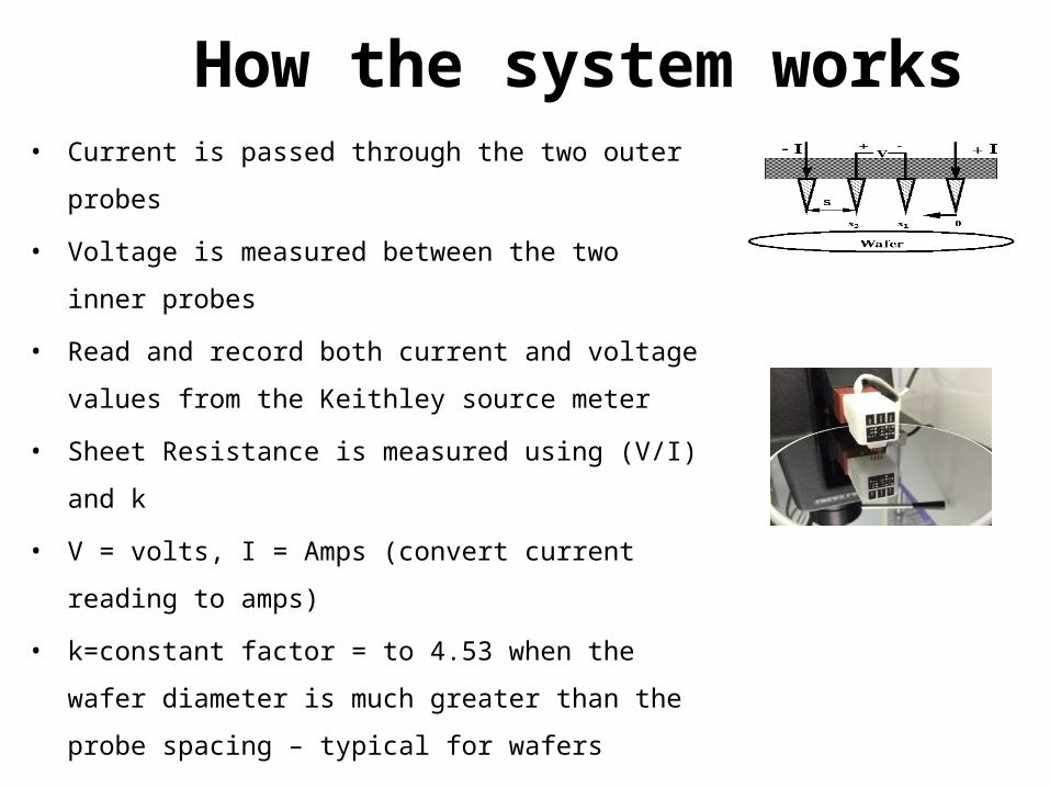
How the system works • Current is passed through the two outer probes
• Voltage is measured between the two inner probes
• Read and record both current and voltage values from the
Keithley source meter
• Sheet Resistance is measured using (V/I) and k
• V = volts, I = Amps (convert current reading to amps)
• k=constant factor = to 4.53 when the wafer diameter is
much greater than the probe spacing – typical for wafers
• Sheet resistance (rs) = (k)(V/I)= ohms/square

For the bulk resistivity of a wafer
• The thickness of the wafer/film
must be known – use calipers or
micrometer block to measure the
wafer thickness
• Convert caliper reading in mm to
um (microns)
• Resistivity of wafer will be shown
on the computer screen
• There is a second k factor but for
our work this k factor is not a
factor and can be ignored
(typically >.995)

To measure the thickness of a waferUse a caliper or the micrometer stage shown below
To turn on, press and hold the right buttonTo turn off, press and hold both buttonsThe reading on the screen is in mm – a reading of .400mm = 400 microns (um)

Procedure for using the Pro-4
Enter thickness in microns (um) as measured
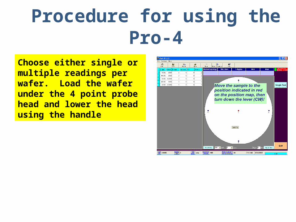
Choose either single or multiple readings per wafer. Load the wafer under the 4 point probe head and lower the head using the handle
Procedure for using the Pro-4

Procedure for using the Pro-4
Lower the probe heading using the contact lever until
the computer screen shows a measurement taking place. Once completed, the screen will show the resistivity and
V/I
Record resistivity in ohm-cm as shown on the screen

Saving the data
• After the measurement is
completed, the resistivity at each
location will be displayed on the left
hand side of the screen.
• When all the points are tested, the
data can be saved and read using
excel

• The Pro-4 can be used to measure resistivity or the thickness. But, either
one has to be known.
• Typically the thickness of the wafer can be measured
• The # of points to be tested and the shape of the sample can be selected.
• A single point or multiple points on the sample can be tested to obtain the
average resistivity.
• The resistivity is automatically displayed when the thickness is entered.
• Additional information is also displayed including V/I
Summary

Sample Wafer CalculationsUsing voltage and current measurements
• A current of 1.0 mA is passed through the wafer and a voltage reading of 0.030 v is noted. I = 1.0 MA = .001 amp
• V/I = .030 v/.001A = 30 ohm• rs = (V/I) k = (.030/.001)(4.53) = (30)(4.53) =
135.9 ohms/square• The wafer is measured as 0.40 mm = .04 cm• r = (135.9)(.04cm) = 5.43 ohm-cm
![Bulk and Piecemeal Auction...And Moticam 2000 Digital Microscopy Camera] [(Qty-2) Signatone #750 probe Micropositioners] [Keithley 2440 5A SourceMeter ; Keithley 2000 Multimeter ;](https://static.fdocuments.us/doc/165x107/5fe198a654fd8c08180feac0/bulk-and-piecemeal-auction-and-moticam-2000-digital-microscopy-camera-qty-2.jpg)