Foundry Flask Punch-Out Machine
81
Central Washington University Central Washington University ScholarWorks@CWU ScholarWorks@CWU All Undergraduate Projects Undergraduate Student Projects Spring 2018 Foundry Flask Punch-Out Machine Foundry Flask Punch-Out Machine Nolan Stockman [email protected] Follow this and additional works at: https://digitalcommons.cwu.edu/undergradproj Part of the Mechanical Engineering Commons Recommended Citation Recommended Citation Stockman, Nolan, "Foundry Flask Punch-Out Machine" (2018). All Undergraduate Projects. 70. https://digitalcommons.cwu.edu/undergradproj/70 This Dissertation/Thesis is brought to you for free and open access by the Undergraduate Student Projects at ScholarWorks@CWU. It has been accepted for inclusion in All Undergraduate Projects by an authorized administrator of ScholarWorks@CWU. For more information, please contact [email protected].
Transcript of Foundry Flask Punch-Out Machine

Central Washington University Central Washington University
ScholarWorks@CWU ScholarWorks@CWU
All Undergraduate Projects Undergraduate Student Projects
Spring 2018
Foundry Flask Punch-Out Machine Foundry Flask Punch-Out Machine
Nolan Stockman [email protected]
Follow this and additional works at: https://digitalcommons.cwu.edu/undergradproj
Part of the Mechanical Engineering Commons
Recommended Citation Recommended Citation Stockman, Nolan, "Foundry Flask Punch-Out Machine" (2018). All Undergraduate Projects. 70. https://digitalcommons.cwu.edu/undergradproj/70
This Dissertation/Thesis is brought to you for free and open access by the Undergraduate Student Projects at ScholarWorks@CWU. It has been accepted for inclusion in All Undergraduate Projects by an authorized administrator of ScholarWorks@CWU. For more information, please contact [email protected].

FOUNDRY FLASK PUNCH-
OUT MACHINE
By:
NOLAN STOCKMAN

2
Table of Contents Abstract ........................................................................................................................................... 5
Introduction ..................................................................................................................................... 5
Motivation ................................................................................................................................... 5
Function Statement ..................................................................................................................... 5
Requirements .............................................................................................................................. 5
Engineering Merit ....................................................................................................................... 6
Scope of Effort ............................................................................................................................ 6
Success Criteria ........................................................................................................................... 6
DESIGN & ANALYSIS ................................................................................................................. 7
Approach: Proposed Solution ..................................................................................................... 7
Benchmark .................................................................................................................................. 7
Performance Predictions ............................................................................................................. 7
Description of Analyses .............................................................................................................. 7
Scope of Testing and Evaluation ................................................................................................ 7
Analysis....................................................................................................................................... 8
Updated Analysis Post Build .................................................................................................... 10
Design ....................................................................................................................................... 10
Calculated Parameters ............................................................................................................... 10
Device Shape ............................................................................................................................ 11
Device Assembly & Attachments ............................................................................................. 11
Tolerances ................................................................................................................................. 11
Technical Risk Analysis ........................................................................................................... 12
METHODS & CONSTRUCTION ............................................................................................... 13
Construction .............................................................................................................................. 13
Part Drawings (Located in Appendix B) .................................................................................. 16
PART DRAWING TREE ......................................................................................................... 18
TESTING METHOD & PROCEDURES ..................................................................................... 19
Introduction ............................................................................................................................... 19
Test 1- Flask Rail Deflection .................................................................................................... 19
Test 2 – Column deflection ....................................................................................................... 20
Test 3 – Sand Removal Percentage ........................................................................................... 22
Test 4 – User Force Required ................................................................................................... 23
BUDGET/SCHEDULE/PROJECT MANAGEMENT ................................................................ 25

3
Proposed Budget ....................................................................................................................... 25
Budget ....................................................................................................................................... 25
Raw Material Suppliers............................................................................................................. 25
Project Management ................................................................................................................. 25
DISCUSSION ............................................................................................................................... 26
Design Evolution ...................................................................................................................... 26
Designed For Manufacturability ............................................................................................... 26
CONCLUSION ............................................................................................................................. 27
APPENDIX A ............................................................................................................................... 28
A-1 Column Design .................................................................................................................. 28
A-2 Column Design .................................................................................................................. 29
A-3 Column Design .................................................................................................................. 30
A-4 Column Design .................................................................................................................. 31
A-5 Column Design .................................................................................................................. 32
A-6 Sizing Punch Head Clevis Pin ........................................................................................... 33
A-7 Fasteners Torque Calculations ........................................................................................... 34
A-8 Sizing Lifting Hook ........................................................................................................... 35
A-9 Flask Rail Design ............................................................................................................... 36
A-10 Sand Collection Bin Design............................................................................................. 37
A-11 Floor Plan Calculation ..................................................................................................... 38
A-12 Tilting Force Calculation ................................................................................................. 39
APPENDIX B ............................................................................................................................... 40
B-1 Column Mounted Arbor Press ........................................................................................... 40
B-2 Adjustable Feet .................................................................................................................. 41
B-3 Punch Out Head Clevis Pin................................................................................................ 42
B-4 Lifting I-Bolt ...................................................................................................................... 43
B-5 Angle Iron Guide Rail ........................................................................................................ 44
B-6 Arbor Press Attachment Plate ............................................................................................ 45
B-7 Column Alignment Plate.................................................................................................... 46
B-8 Column Base Plate ............................................................................................................. 47
B-9 Column Gusset Plate .......................................................................................................... 48
B-10 Column Side Plate............................................................................................................ 49
B-11 Lifting Hook Attachment Plate ........................................................................................ 50
B-12 Tubing Cross Member (2 Hole Standard) ........................................................................ 51

4
B-13 Tubing Cross Member (2 Hole Modified) ....................................................................... 52
B-14 Square Tube Leg .............................................................................................................. 53
B-15 Foot Attachment Block .................................................................................................... 54
B-16 Punch Out Head Attachment Tube .................................................................................. 55
B-17 Punch Out Head Top Plate ............................................................................................... 56
B-18 Punch Out Head Center Square ....................................................................................... 57
B-19 Punch Out Head Angle Plate ........................................................................................... 58
B-20 PUNCH OUT HEAD WELDMENT (PARTS B16-B19) ............................................... 59
B-21 Basket Base ...................................................................................................................... 60
B-22 Catch Bin Left Side .......................................................................................................... 61
B-23 Catch Bin Right Side ....................................................................................................... 62
B-24 Catch Bin Back Panel ...................................................................................................... 63
B-25 Catch Bin Sand Deflector ................................................................................................ 64
B-26 Tubing Cross Member (3 Hole Standard) ........................................................................ 65
B-27 Bill of Materials ............................................................................................................... 66
APPENDIX C – Parts List ............................................................................................................ 66
APPENDIX E – Schedule ............................................................................................................. 68
Gantt Chart ................................................................................................................................ 68
Appendix F – Material Record ..................................................................................................... 73
Appendix G – Testing Data .......................................................................................................... 75
Test 1- Flask Rail Deflection .................................................................................................... 75
Test 2- Column Deflection........................................................................................................ 75
Test 3 - Sand Removal .............................................................................................................. 76
Test 4 – User Force Required ................................................................................................... 77
Appendix H – Data Evaluation Sheets.......................................................................................... 78
Appendix I – Testing Conclusion ................................................................................................. 79
Appendix J – Resume ................................................................................................................... 80

5
Abstract
In the green sand molding process olivine sand is compacted into flasks that are used for the
molding and pouring process in a foundry. These sands are difficult to remove after the pour has
been made. In Central Washington University’s foundry the sands are currently being removed
with handheld rams. To improve on this process a Foundry Flask Punch Out machine was
designed. The machine was designed to utilize a wall mounted rack and pinion style press. The
supporting elements of both the flask and press were engineered with deflection requirements in
mind. The machine was made to fit into the current sand handling system without any addition
modifications. Testing the Foundry Flask Punch-Out machine shows that it is and improvement
from the previous process. The machine removes sand efficiently and with little effort. This
machine also improved of safety as it removes interaction with hot foundry sands and castings.
Introduction
During the green sand molding and metal casting process flasks are filled with compacted sand
and molten metal. The current method at Central Washington University for removing the sand
and casting from the flasks is to use hand tools. This method can be both difficult and mildly
dangerous (from hot sand and castings).
Motivation The motivation for this project comes from a need for a device that would eliminate the current
process of removing compacted foundry sands from flasks by hand at Central Washington
University.
Function Statement A device that will remove sand from multiple sized foundry flasks.
Requirements The design must meet the following requirements.
• Removes 90% of sand from flask
• Removes casting from flask
• Cycle time must be more efficient that current process
• Directs sand to an easy to remove place
• Can withstand a 2000 lb. load on the sand flask
• Needs to accommodate 70% of CWU’s current flask sizes
• Needs to have an ergonomic table height (24”-40”)
• The user must not need to apply more than 50lb force to the machine
• The system must be safe (no tipping hazard)
• Budget is no more than $2,000 (not including labor)

6
Engineering Merit The design of the flask punch out table involves many engineering calculations. Most
engineering merit will come from static engineering based on the loads applied to a flask filled
with compacted sand. Manufacturing engineering principles are going to be used to optimizing
the design by efficiently consuming raw materials.
Scope of Effort The scope of this project is going to focus on the physical actuation of a ram to remove the
compacted foundry sand and casting from the flask. The machine will require a stand to hold the
flask, support a rack and pinion style ram, and catch the removed sand and casting.
Success Criteria The design will be successful if it can remove the complete casting and 90% of the sand by
weight with a single operation of the ram.

7
DESIGN & ANALYSIS
Approach: Proposed Solution The approach of this project is to redesign the way compacted foundry sands are removed from
flasks after the casting has been poured. The current process is done with hand held rams. While
the current process is simple and works, the implantation of a Flask Punch Out machine would
greatly improve the process and mitigate safety concerns.
The design of the foundry flask punch out will be guided by both the benchmarks of current
industry standards for punch out machines. In addition this design will be greatly influenced by
the current tooling in the foundry. The accommodation of multiple flask sizes will be the largest
guiding factor in this design.
Benchmark Foundry flask punch-outs are relatively common in the foundry industry. Typically, most are
custom built and sized for an operations flask sizes. This project will be compared to the function
and performance of such devices.
Performance Predictions The performance of the foundry flask punch out will be evaluated by comparing the machines
ability to remove compacted sands and castings from flasks in respect to the current operation
(punching out sand with a handheld ram) in CWU’s foundry. For removing sands from the
foundry flasks and feeding them into an elevator conveyor the current operation takes 2-6
minutes per flask, depending on flask size and operator. The new operation is aimed to take less
than 1:30 to complete the same operation. This means the machine is aimed to have a 33%-400%
increase in efficiency.
Description of Analyses The analyses of the foundry flask punch out focuses mainly on the force that is required to
“punch out” the compacted foundry sands from current flask sizes. By factoring in tyical green
sand shear forces as well as different scenarios it seemed antique to design the machine for a
2000 lb. max load on the flasks. From this test the arbor press is able to be sized appropriately so
the user does not have to apply more than 50 lbf. to press the sands out from the mold. The
reaction forces on the machine will take ample engineering work to find and define the support
system for this operation. These support system includes but is not limited to the rails supporting
the flask, the column supporting the arbor press, the arbor press shear head, and the general
framework of the machine.
Scope of Testing and Evaluation The best way to test and evaluate the performance of the Foundry Flask Punch Out Machine is
through timed use and physical calculations. The performance of the machine will be tested
based on its predicted deflections under a 2,000 lb load as well as the sand removal percentage.

8
The deflections tests will require the use of dial indicators as well as a load cell. The sand
removal percentage test will be done using a standard 12”x14” flasks.
Analysis The analysis for the machine started with finding the size of a punch head that would be able to
go through all flask sizes that the machine will be capable of handling. Finding the size of the
punch out head determined the shear area of the sand that will be punched out of each flask.
Research shows that the approximate shear area for the green sand would produce a maximum
required shear load of 1,500 lbs. From this analysis the machine was analyzed for a maximum
load of 2000 lb.
The calculated parameter of a maximum load of 2000 lb. leads to most of the deflection
calculations that were done in this project. A large area of analysis in this project revolves
around the support column that holds a column mounted arbor press (drawing in appendix B-1)
above flasks that are loaded onto angle iron rails. In appendix A-1: A-4 parameters for the
column and deflection requirements area addressed.
In Appendix A-1 a ridged deflection requirement of 1/64” was established for the support
column that holds the arbor press above the loaded foundry flask. The 2000 lb. force was
converted into a moment at the end of a cantilever beam. This method of analysis seemed
appropriated due to the comparative thickness and rigidity of both the arbor press and the
extended section at the top of the beam. The deflection that is unaccounted for in these sections
will be negligible when compared to that of the long portion of the column. The deflection
requirement will be measured 16 ¼” from the columns base plate due to that being the length
that is perpendicular to the axis of rotation that the arbor press will produce a moment about. By
analyzing the beam as a cantilever beam with a moment on its end it was found that a moment of
inertia about its bending axis must be 4.7 in^4 to produce a 1/64” deflection when made from A-
36 steel plate.
Appendix A-2 shows the design of the column about its bending axis. This design was made to
produce a moment of inertia value of 4.7 in^4 with respect to this axis. The column design was
established to be made from two plates separated by the distance needed to mount the arbor press
correctly. By constraining the height of the beam (with respect to the bending axis) to 5 inches,
due to the overall space available to the machine, the base thickness was able to be solved for.
The solution held a desired base thickness of .2256 inches. This value was rounded to .25 inches
so common ¼” A-36 plate could be used for construction. Appendix A-3 re-analyzes the findings
from Appendix A-1 with an established beam shape so the actual theoretical deflection could be
calculated and tested against at a later date. A-3 establishes that the deflection will yield .014”
when the arbor pressed is loaded to 2000 lb. This deflection is less than the 1/64” deflection
requirement by approximately .0016”.
Appendix A-4 & A-5 analyze is the column and its welding to the base will be able to withstand
the same moment that the beam was analyzed for deflection. Appendix A-4 shows that at the
beam base there will be a stress of approximately 11,600 psi at the face furthest from the bending
axis on both ¼” plates. The 11,600 psi bending stress is less than the 36 ksi yield value for A-36
steel. This establishes that the column will not break when the arbor press is loaded to 2000 lb.

9
Appendix A-5 analyses the same principle as A-4 with respect to the welds that hold the column
to the column baseplate. The column will be welded to the baseplate with 7018 welding rod
which has an ultimate tensile strength of 70,000 psi. To ensure the welds will hold during
loading a minimum weld width was calculated from the minimum moment of inertia value with
respect to the bending axis. By welding along both sides of both plates in the column a weld
width of .0207” will produce a bending stress of 70,000 psi at the weld furthest from the bending
axis. A single pass weld will produce a weld thickness larger than .0207”. This establishes that
the designed weld plan for the column is sufficient.
The requirement to remove 90% of foundry sands from the flask. To do this a punch head of 9”x
9” was created with an inverse tetra pyramidal structure to concentrate the shear force as the
punch head comes into contract with the compacted foundry sands. This head will be attached to
the arbor press with a clevis pin. Appendix A-6 evaluates the size of the pin in order to withstand
a 2000 lb. load by the arbor press. By making the pin from 316 stainless steel the pin size was
determined to be 3/8” with a X1.5 factor of safety applied to it.
In this design most of the members will be welded in place. Only the arbor press and the 16
gauge sheet metal basket will be bolted onto the design. The torque values for the grade 5 bolts
that will be used is found in Appendix A-7. In addition a bolt on ½-13 thread I-bolt will be
placed at the top of the machine directly over the machines center of mass. This will fulfill the
requirement of the machine being able to be easily moveable. The sizing calculation for this I-
bolt can be found in Appendix A-8.
To fulfill the requirement ergonomic flask loading and unloading angle iron guide rails were
used to direct flasks below the modified arbor press when the user loads a flask from the
machines side. Appendix A-9 shows the required deflection of less than .005” when an 18” x 12”
flask is loaded to 2000 lb. By using 2” x 1.5” x ¼” angle iron and calculating the moment of
inertia about the 2” flange the deflection was calculated to be .0024” which is less than .005” by
.0026”.
This design has a requirement that when the sand and casting are removed from the flask that
they are transferred into a container that allows for easy removal. To account for this a sand
collection bin will be made according to the specifications calculated in Appendix A-10. These
specifications are produced from the desire to hold 85% of the sand volume from the largest
flask size below the extraction point. A tapper was added to the collection bin from the removal
point to allow for a standard flat nose shovel to be used to remove the foundry sands from the
collection bin.
The placement of this machine will be near sand elevator. In this area there is limited space and
it is important to ensure that machine will be able to fit in the required area. Appendix A-11
calculates the footprint the machine will use. This information will be used in the planning of the
placement of the machine.
Lastly it is important that the machine does not tip easily. The tilting force was calculated in
Appendix A-12 to see what the estimated tilting force is when applied at the highest point on the
machine. This force was found to be 58.7 lb. when applied at the top of the column in respect to

10
Figure 2 - Final Design
the machines Y axis. This calculation ensures that the machine will not be tipped accidently from
any side loading. The machine utilizes 2”x2”x1/4” for its frame. The use of this relatively heavy
material lowers the center of mass on the machine and makes the machine less likely to tilt from
a unintended side load.
Updated Analysis Post Build During the construction phase of this project there was little to no modifications required from
the original design that would affect the analysis of the Foundry Flask Punch Out machine. Most
modifications made were minor and due to fitment issues. One example is cutting weld reliefs
into the sheet metal sand basket. This modification allowed for the basket to be assembled easier
and did not change any analysis relating to the basket itself.
Design Below is the progression of the 3D design that has been done is Solidworks 2017.
Figure 1 - Initial Design
Calculated Parameters Discussion of the calculated parameters is in the analysis section above. Calculation can found in
Appendix A as follows.
• Arbor Press Support Column Design……………………………….....…………….A1-A4
• Weld Size for Support Column………………………………………….……………... A5
• Punch Out Head Clevis Pin Size…………………………………………………...……A6
• Bolt Torque Values……………………………………………………………...………A7
• Lifting I-Bolt Size……………………………………………………………………….A8
• Guide Rail Sizing………………………………………………………………………..A9

11
• Sand Collection Bin Sizing…………………………………………………………….A10
• Floor Plan Calculation…………………………………………………………………A11
• Machine Tilting Force Calculation………………………………………………….…A12
Device Shape The shape of this flask punch out machine will be much different than most industry
benchmarks. The device will be a table like frame with a clear opening for sand to pass through
near the center of the table top. Behind the clear opening will be a support column for a vertical
mount arbor press. The Abor Press will be supported by the column and positioned above the
clear opening on the table. In between the table legs and below the table top there will be a 3
sided catch basket that will catch the sand and castings that are pressed through the clear
opening. The removal of one side of the basket will allow the user to shovel the sand into the
current bucket elevator and remove the casting. This design is unique to flask punch out
machines. This is largely due to the scale of Central Washington University’s foundry and
variety of flask sizes.
Device Assembly & Attachments The foundry flask punch out machine will utilize both welding and through bolting to assemble
the device and its attached components. The device will consist of a frame weldment that will
include the frame legs, cross members, table top, and lastly the arbor press attachment column.
This weldment will be done with an ARC welder utilizing 7018 rod. The frame legs will be
supported with threaded adjustable feet. The arbor press will be bought as a single unit from
McMaster-Carr and will be bolted to the arbor press attachment column with four 9/16 bolts and
nuts. Attached to the arbor press ram will be the punch through head. This head will be a
pyramidal weldment with a center tube that has an internal diameter .005-.010 less than the OD
of the arbor press. This head will be attached to the arbor press ram with a 3/8” 316 stainless
steel pin. The basket that will catch the falling sand and casting will be made from 16 gauge cold
rolled low carbon steel. The sheets will be ordered in strips and flame cut to their net shape using
Central Washington University’s plasma table. Once received the basket will be bent with sheet
metal presses and tack welded into shape. The basket will be attached to the frame legs and cross
members via through bolting.
Tolerances The different parts for this weldment and assembly will have a variety of tolerances associated
with them. In general most of the welded pieces will have cut tolerances of +/-.030. The welded
assembly will be expected to have overall dimensions within + 0” - 1/8” to be considered in spec.
Perpendicular members will be held to a +/- 3 degree tolerance from perpendicular. Holes will
have fractional dimensions associated with them, tolerances produced from standard size drills
and end mills will suffice. The pin connection that attaches the punch out head to the Arbor
press ram will be drilled with a 3/8” center cutting end mill and fit with a 3/8” clevis pin that is
pre toleranced for a hand fit.

12
Technical Risk Analysis This machine has several potential risks involving forces, heat, and ergonomics. Due to the fact
that the Foundry Flask Punch Out machine will be operated by a user applied force the technical
risk from the punch out ram will be considered as low. The probability of an user extremity
being caught between the punch out ram while the user is operating the machine will be deemed
as an improbable unintentional occurrence. Ergonomics is another technical risk. This is because
the flask will be loaded and unloaded by hand. A design that does not allow for an ergonomic
table height and loading procedure could cause undo strain on the users body. Lastly the
direction of the hot sand and casting from the flask will be encompassed in the design to mitigate
risk. The sand and casting will have to be directed into the catch basket in a fashion that there
will be no spill out or splashing while being ergonomic so a user can removing the casting and
sand with a standard flat nose shovel.

13
METHODS & CONSTRUCTION
Construction The construction of the Foundry Flask Punch-Out consisted mostly of fabrication done at Central
Washington Universities (CWU) welding lab in addition to small machining tasks that were
performed in CWU’s machine shop.
A majority of the framework for the Foundry Flask Punch Out consisted of 2”x2”x 3/16”
wall steel square tubing. Attached to the main framework was a column the supports the arbor
press that is made of ¼” steel flat bar. Below the column is a sheet metal basket that was made of
16 gauge steel.
Part 1- Material Planning
The design of the Foundry Flask Punch Out allows for manufacturability. Many of the members
were designed so they could be ordered in there near net shape or easily cut to shape. Many parts
on this project were designed to be cut with CWU’s plasma table. For example all of the
members of the column structure are made from ¼” steel plate. This allows for all the members
to be cut at once on the plasma table. The image below shows several parts that are nested into
an area of 10” wide. This made it
possible to order a ¼”x10” flat bar cut to
length and have the ability to cut it on the
plasma table.
Part 2- Sawing
To begin the manufacturing process of the foundry flask
punch out machine all the raw materials needed to be sawn
to overall length. CWU has a horizontal hydraulic band saw
that made quick work of cutting all the structural members
to length. Part of the design for manufacturability included
only having two standard lengths for the square tubing.
This made it so the saw stop only needed to be adjusted
twice.
Part 3 – Machining pre-fabrication
In a majority of the steel square tubing members there are
tapped ¼-20 holes that allow for the mounting of the sheet
metal basket. The drilling and tapping of these members
was done before welding in order to allow for the use of a
drill press. The only other parts that required machining
Figure 3-Nested parts
Figure 4 - Raw Material Sawn To Length

14
was the punch out head attachment tube (part B-16) and drilling a hole to accept a clevis pin in
the arbor press shank.
Part 4- Plasma Table Cutting
The use of CWU’s plasma table made quick work of producing parts. By nesting like parts in
raw material they could be cut in one operation instead of multiple setups. Parts from the
Foundry Flask Punch out were nested in Solidworks and then turned into a .DXF file for the
plasma table to read. In addition to the column components being cut on the CNC plasma table
the sheet metal basket components were cut from their near net shape to their final shape.
Part 5- sheet metal work
After the sheet metal components were cut to shape mounting holes were drilled and the proper
bends were made. Bending the sheet metal was challenging due to the equipment available at
CWU. One of the bends overlapped in the tooling setups
which made it so some corners had to be bent back into
alignment manually and hammered until flush with the
existing bend. While inconvenient this process did not affect
the final product or its function in the foundry Flask Punch
Out machine.
Part 6- Welding
Welding of the Foundry Flask Punch out was one of the
longest and most challenging tasks. While the process was not
difficult in itself, ensuring alignment of all parts was. Most of
the welding was done alone without a partner or jig which
made some structural members difficult to hold in place while
welding. Overall the frame and attached column turned out
very well.
Figure 5 - .dxf file & actual cut material
Figure 6 - drilling and chamfering basket
holes

15
Part 7 – Basket Assembly
Assembling the sheet metal basket proved to be challenging due to overly tight tolerances and
the lack of weld reliefs. During the assembly of the basket weld reliefs had to be ground into
certain areas using an angle grinder. This made it so the basket could be put in place and attached
with ¼-20 bolts and washers.
Part 8 – Completed Assembly without Rack and Pinion Press
➔
Part 9 – Painting Completed Assembly
Once the final assembly was completed the Foundry Flask Punch-Out Machine was brought to
the paint room in Central Washington University’s Houge Technology Building. Here the
machine was degreased and painted.
Figure 8-Painting final assembly
Figure 7 - Solid model compared to physical model

16
Part Drawings (Located in Appendix B) • Drawings for Arbor press
o B-1
▪ Column Mounted Arbor Press
• Drawings for Arbor press Column
o B-6
▪ Arbor Press Attachment Plate
o B-7
▪ Column Alignment Plate
o B-8
▪ Column Base Plate
o B-9
▪ Column Gusset Plate
o B-10
▪ Column Side Plate
o B-11
▪ Lifting Hook Attachment Plate
• Drawings for General Frame
o B-5
▪ Angle Iron Guide Rail
o B-12
▪ Tubing Cross Member (2 Hole Standard)
o B-13
▪ Tubing Cross Member (2 Hole Modified)
o B-14
▪ Square Tube Leg
o B-15
▪ Foot Attachment Block
o B-26
▪ Tubing Cross Member (3 Hole Standard)
• Drawings for Punch out Head
o B-16
▪ Punch Out Head Attachment Tube
o B-17
▪ Punch Out Head Top Plate
o B-18
▪ Punch Out Head Center Square
o B-19
▪ Punch Out Head Angle Plate

17
o B-20
▪ PUNCH OUT HEAD WELDMENT (PARTS B16-B19)
• Drawings for Sheet Metal Basket
o B-21
▪ Basket Base
o B-22
▪ Catch Bin Left Side
o B-23
▪ Catch Bin Right Side
o B-24
▪ Catch Bin Back Panel
o B-25
▪ Catch Bin Sand Deflector
• Drawings of Attachments
o B-2
▪ Adjustable Feet
o B-3
▪ Punch Out Head Clevis Pin
o B-4
▪ Lifting I-Bolt
• BILL OF MATERIAL DRAWING
o B-27

18
PART DRAWING TREE
B-1
COLUMN MOUNTED
ARBOR PRESS
B-6
Arbor Press
Attachment Plate
B-16
Punch Out Head
Attachment Tube
B-10
Column Side
Plate
B-7
Column Alignment
Plate
B-8
Column Base
Plate
B-4
Lifting
I-Bolt
B-9
Column Gusset
Plate
B-11
Lifting Hook
Attachment Plate
B-14
Square
Tube Leg
B-13
Tubing Cross Member
(2 Hole Modified)
B-3
Punch Out Head
Clevis Pin
B-17
Punch Out Head
Top Plate
B-15
Foot Attachment
Block
B-12
Tubing Cross Member
(2 Hole Standard)
B-19
Punch Out Head
Angle Plate
B-18
Punch Out Head
Center Square
B-26
Tubing Cross Member
(3 Hole Standard)
B-5
Angle Iron
Guide Rail
B-2
Adjustable Feet
B-21
Basket Base
B-24
Catch Bin
Back Panel
B-22
Catch Bin
Left Side
B-23
Catch Bin
Right Side
B-25
Catch Bin Sand
Deflector

19
TESTING METHOD & PROCEDURES Introduction The foundry flask punch out machine has several areas that will be tested. The machine is
designed to press sand and castings out from an array of flask sizes. The machine has been
designed to handle to loads with appropriate deflection requirements in addition to being
ergonomic for the user. Both the functionality and physical properties of the machine will be
tested. The physical properties of this machine will be tested via an applied 2,000 lb. load and
recording deflections in supporting members. The machines function will be tested by using the
machine on filled 12”x14” flasks and calculating the sand removal percentage by weight. Lastly
the a usability test will be performed with a scale to ensure and record that a user does not need
to exceed 50 lbs. of force to remove sand from any given flask.
Test 1- Flask Rail Deflection INTRODUCTION
• The flask rail deflection test is to measure how much the center of the back flask rail deflects when a flask is loaded to 2,000 lbf. A testing Jig and bottle jack were used to create this force. It is predicted that the flask rail will deflect .0012 inches. This predicted value was concluded from a uniformly loaded beam with fixed ends. Reference analysis sheet A-9.
METHOD & APPROACH
• To perform this test a testing jig was created to mount to the column in replacement of the arbor press used. This was so a bottle jack could be used in conjunction with a Fluke load cell to accurately load the flask rails. Accuracy is limited by the deflections across the machine when loaded. This will affect the measurement of the rail deflection. The precision of this test will be limited by the magnetic dial indicator used to measure the deflection. This dial indicator is scaled in .001 inches with a readable accuracy of .0005” inches. When loaded dial indicators were pictured so they could be reviewed at a later date. Data will be presented in a comparative analysis with the predicted value.
TEST PROCEDURE
• Testing was completed on April 11, 2018. The test took 1 hour to setup and complete. The test was done in Central Washington University’s Power Tech Lab with the help from Matt Burvee, CWU Lab Technician. Resources needed were a Fluke Load cell with a computer to transmit data, a digital 0-200 lb. scale, a standard automotive bottle jack, a testing jig that provides attachment to the column and a surface for the bottle jack to press on, a standard steel 12”x18” foundry flask, and lastly a 1” thick 12”x18” (or greater) steel plate.
o Step 1 ▪ Weigh and record foundry flask and steel plate.
o Step 2 ▪ Bolt testing jig onto the column of the Foundry Flask Punch-Out

20
machine o Step 3
▪ Place the magnetic dial indicator on the machine frame at the front middle 2”x2” tubing cross member. Move the dial arm so the dial is perpendicular to the center of the back flask rail. Make sure the dial is reading within .5” of center on the rail.
o Step 4 ▪ Center foundry flask on the machines rails and cover with the steel
plate. o Step 5
▪ Place bottle jack under the testing jig and place the Fluke load cell in between the bottle jack and steel plate.
o Step 6 ▪ Center the load cell and bottle jack on the steel plate within .5” of
center. o Step 7
▪ Calculate the additional weight of the flask and plate and reduce it from the 2000 lb. load. Now a load value will be acquired to reach when loading the machine.
o Step8 ▪ Apply the calculated load via bottle jack.
o Step 9 ▪ Read and record the value shown on the dial indicator.
o Step10 ▪ Repeat and record test 3 times and average the data
• Technical Risk
o The flask, steel plate, and testing jig have weights exceeding 40 lbs. Lift carefully and use a floor crane or lifting cart if needed. Do not place any body part in-between the bottle jacks loading surfaces when loading the jack.
DELIVERABLES/DISCUSSION ▪ By following the listed test produce a deflection value of .0020 inches was acquired.
The test was preformed 3 times and the same result was consistently repeated. The predicted deflection value was .0012 inches. This leaves the actual value .0008 inches over the predicted. However, the deflection requirement for this project was to be less than .005 inches when loaded to 2000 lbf. This parameter was achieved.
Test 2 – Column deflection INTRODUCTION
▪ In the design of the Foundry Flask Punch-Out machine the column was designed with a deflection requirement when a 2000 lb load was present on the arbor press used. At 16.25” from the baseplate the column was predicted to flex .014” in the

21
perpendicular direction (reference analysis A-3).
METHOD & APPROACH ▪ To perform this test a testing jig was created to mount to the column in replacement
of the arbor press used. This was so a bottle jack could be used in conjunction with a Fluke load cell to accurately load the flask rails. Accuracy is limited by the deflections across the machine when loaded. This will affect the measurement of the column deflection. The precision of this test will be limited by the magnetic dial indicator used to measure the deflection. This dial indicator is scaled in .001 inches with the accuracy of .0005” inches. When loaded dial indicators were pictured so they could be reviewed at a later date. Data will be presented in a comparative analysis with the predicted value.
TESTING
▪ Testing was completed on April 11, 2018. The test took 1 hour to setup and complete. The test was done in Central Washington University’s Power Tech Lab with the help from Matt Burvee, CWU Lab Technician. Resources needed were a Fluke Load cell with a computer to transmit data, a digital 0-200 lb. scale, a standard automotive bottle jack, a testing jig that provides attachment to the column and a surface for the bottle jack to press on, a standard steel 12”x18” foundry flask, and lastly a 1” thick 12”x18” (or greater) steel plate
o Step 1 ▪ Weigh and record testing jig
o Step 2 ▪ Bolt testing jig onto the column of the Foundry Flask Punch-Out
machine o Step 3
▪ Place the magnetic dial indicator on a secure magnetic surface that is separate from the machine. Position the indicator so it is reading on one side of the column 16.25” from the base plate in a perpendicular position.
o Step 4 ▪ Center foundry flask on the machines rails and cover with the steel
plate. o Step 5
▪ Place bottle jack under the testing jig and place the Fluke load cell in between the bottle jack and steel plate.
o Step 6 ▪ Center the load cell and bottle jack on the steel plate within .5” of
center. o Step 7
▪ Calculate the additional weight of the testing jig and add it to the 2000 lbf load applied by the bottle jack.
o Step8 ▪ Apply the calculated load via bottle jack.
o Step 9

22
▪ Read and record the value shown on the dial indicator. o Step10
▪ Repeat and record test 3 times and average the data. o Step 11
▪ Reposition dial indicator to read perpendicular to the baseplate in line and within .5” in front of one column side.
o Step 12 ▪ Repeat the previous load and record the distance the baseplate
bowed upward. o Step 13
▪ Calculate angle and deflection of column
• Technical Risk o The flask, steel plate, and testing jig have weights exceeding 40 lbs. Lift
carefully and use a floor crane or lifting cart if needed. Do not place any body part in-between the bottle jacks loading surfaces when loading the jack.
DELIVERABLES/DISCUSSION ▪ By following the listed test produce a deflection value of .063”. This is .049” larger
than the predicted value but does not include the addition of the angle created by the baseplate flexing upward. The baseplate flexed upward .008 inches.
Test 3 – Sand Removal Percentage
INTRODUCTION ▪ The creation of the Foundry Flask Punch-Out machine was motivated by the need
to remove sand from flasks in an improved fashion form the current method. This test is to evaluate the machines performance against the requirement of having 90% of sand removed in a single operation of the machine. This test will require the use of a 0-200lb scale, four 12”x14” flasks, Green diamond olivine sand mixed to a moisture percentage of 4-10%, and lastly a handheld ram to compact the sand.
METHOD/APPROACH ▪ By using the current green sand handling equipment at CWU sand will be able to
be mixed to the proper moisture content. Flasks weight will be acquired 3 times during this test. Once before being filled, once after, and lastly after punch out has occurred. The Scales accuracy is to the 1/100th of a lb. This approach will give adequate results that will be able to be compared against the predicted 90% sand removal rate.
TESTING ▪ Testing will be performed on May 3rd 2018 . Resources need will be the correct
size flasks and green sand as well as the sand handling equipment that is already in place in the CWU foundry.
o Step 1

23
▪ Select 4 12”x14” flasks and record their weight o Step 2
▪ Use sand handling equipment to mix sand and water until the moisture percentage is between 4-10%.
o Step 3 ▪ Compact sand into molds using a handheld ram
o Step 4 ▪ Weight the four flasks after filled
o Step 5 ▪ Center each flask on the guide rails of the Foundry Flask Punch-out
machine and use the machines pull arm to complete one punch out cycle on each flask.
o Step 6 ▪ Carefully remove each flask from the machine to weigh and record.
o Step 7 ▪ Calculate the sand remove percentage in each flask by taking into
account the weight of the flask. ▪ Technical Risk
o The user will have to be careful when handling flasks due to the weight. The user must keep hands free and clear of the arbor press as it comes into contact with the mold.
DELIBVERABLE/CONCLUSION ▪ The test was performed on May 3rd 2018 and was considered successful. The sand
removal percentage was on average 92% from the four flasks used. One mold was below the target value by having a 86% sand removal rate. It should be notated that once the punch out occurred the remainder of the sand was relived of compression and could easily be pressed out by hand if desired.
Test 4 – User Force Required
INTRODUCTION ▪ The creation of the Foundry Flask Punch-Out machine was motivated by the need
to remove sand from flasks in an improved fashion from the current method. This test is to evaluate the required user force to operate the machine.
METHOD/APPROACH ▪ By using the current green sand handling equipment at CWU sand will be able to
be mixed to the proper moisture content. Sand will be filled and compacted into 12”x14” molds so they can be removed by ram on the machine. During removal the machines pull arm will be oriented so a handheld scale can be attached to the end of the arm. The scale will be monitored so the maximum force is recorded.
TESTING ▪ Testing will be performed on May 3rd 2018 in coalition with test 3.

24
o Step 1 ▪ Select 4 12”x14” flasks
o Step 2 ▪ Use sand handling equipment to mix sand and water until the
moisture percentage is between 4-10%. o Step 3
▪ Compact sand into molds using a handheld ram o Step 4
▪ Center each flask on the guide rails of the Foundry Flask Punch-out machine
o Step 5 ▪ Attach a handheld 0-100lb. scale to the end of the pull arm.
o Step 6 ▪ Ensure the scale is pulled in a perpendicular fashion in respect to the
pull arm. o Step 7
▪ Monitor the scale during punch out and record the maximum pull force.
▪ Technical Risk o The user will have to be careful when handling flasks due to the weight. The
user must keep hands free and clear of the arbor press as it comes into contact with the mold.
DELIBVERABLE/CONCLUSION ▪ The test was performed on May 3rd 2018 and was considered successful. During
punch out all of the max forces performed by the user were less than 30 lbs. This makes this test a success considering the project requirement was to have the user emit no more than 50 lbf. during punch out.

25
BUDGET/SCHEDULE/PROJECT
MANAGEMENT
Proposed Budget From preliminary research and knowledge of current steel prices the estimated budget was set to
$2000. This money will come from both Central Washington University’s Foundry Education
account as well as industry support for the project.
Budget Comparing the material prices to that of the original budget shows the project to be within the set
budget. In the original estimate the prices for the steel were estimated. The proposed budget was
largely based on the estimated cost of the steel and the price of the wall mounted arbor press.
The arbor press alone cost just over $1,000. The price of the arbor press was a driving factor in
setting the budget to $2,000. Below is a table showing the cost of the steel order from Haskins
Steel as well as the arbor press and miscellaneous parts order from McMaster Carr.
ORDER PRICE (TAX
INCLUDED)
HAKSINS STEEL $496.96
MCMASTER CARR $1125.15
TOTAL $1622.11
*order details listed below
All parts were ordered on 1/15/2018. The material from each vendor arrived within 7 business
days.
Raw Material Suppliers Materials for this project will be acquired from outside vendors. These materials will be able to
be acquired from two primary suppliers. These suppliers are Haskins Steel and McMaster-Carr.
All of the structural steel will be ordered through Haskins steel. The arbor press that will be used
to punch out the sand will be acquired through McMaster-Carr. This is because McMaster-Carr
is a reputable vendor and is one of two vendors that sells the column mounting arbor press that is
required for this device. Fasteners will be a minor cost in this project and will be ordered in
conjunction with the arbor press from McMaster-Carr for convenience and shipping costs.
Project Management • Human Resources
o Dr. Craig Johnson: CWU Professor
o Charles Pringle: CWU Professor

26
o Ted Bramble: CWU Professor
o Matt Burvee: CWU Lab Technician
• Physical Resources
o The physical resources available will all be held within CWU’s Hogue ETSC
building. The buildings welding and sheet metal lab will be used for a majority
of the construction of the Foundry Flask Punch Out. Other resources that will be
used include but are not limited to, the buildings machine shop (for drilling and
tapping operations), and the ventilated paint booth.
• Computer Resources
o This project will be fully designed in Solidworks. This is a 3D modeling and
assembly program that allows for creating a full 3D model of parts and
assemblies.
DISCUSSION
Design Evolution From the beginning of the quarter it was known that the project would take a considerable
amount of time to design effectively. By the nature of the project and the environment that it
would operate in the design would have to accommodate for many unknown variable and
excessive abuse. It was also know that the project would involve a multitude of parts and
systems that would have to work with and around each other. From the beginning it was known
that the project would consist primarily of welding. In the first design concept there were several
machined areas such as the flask grove that has sense been eliminated with angle iron rails. With
help from industry advice and professor consulting a series of refinements were made on the
design to make it both more ergonomic and easier to manufacture. In addition the first design
was overly robust in several aspects. By reducing material sizes in several areas the machine now
will use less material in its construction.
Designed For Manufacturability In addition the evolution of the design there were several elements that were changed that will
make the design easier to manufacture. Several areas were using plate steel that was too thick to
be used on the schools plasma table. By reducing these plate thickness down to ¼” the parts can
now be cut on the CNC plasma table. This will save time from shaping the parts using other
methods or it will save costs from having the steel supplier preform this process at a billing rate.
In addition throughout the design of the project parts were carefully designed so loose tolerances
could be held and the same end result could be achieved. The loose tolerances that were applied
allow for many of the parts to cut on a band saw, plasma table, or shear press. These methods of
producing parts come with less production time that machining methods.

27
CONCLUSION
There is no doubt that the Foundry Flask Punch Out machine will work and be an improvement
of the current process of removing foundry sands. There are little foreseen trouble in the
manufacturing process of this machine due to its robust simplicity and manufacturability. The
machine will produce faster cycle times than the current method of removing foundry sands from
flasks. The improvements in cycle time will be recorded after the machine is build and tested.
The robust requirements and design of the machine have made the design built to last. There are
few concerns about parts that will hold up to the abusive foundry environment. Most parts
affected by the loading of the machine were well below their yield strength values which
removes most all concerns of fatigue in parts. The design was built with safety in mind leaving
no significant safety concerns for the machines operation.

28
APPENDIX A
A-1 Column Design

29
A-2 Column Design

30
A-3 Column Design

31
A-4 Column Design

32
A-5 Column Design

33
A-6 Sizing Punch Head Clevis Pin

34
A-7 Fasteners Torque Calculations

35
A-8 Sizing Lifting Hook

36
A-9 Flask Rail Design

37
A-10 Sand Collection Bin Design

38
A-11 Floor Plan Calculation

39
A-12 Tilting Force Calculation

40
APPENDIX B
B-1 Column Mounted Arbor Press

41
B-2 Adjustable Feet

42
B-3 Punch Out Head Clevis Pin

43
B-4 Lifting I-Bolt

44
B-5 Angle Iron Guide Rail

45
B-6 Arbor Press Attachment Plate

46
B-7 Column Alignment Plate

47
B-8 Column Base Plate

48
B-9 Column Gusset Plate

49
B-10 Column Side Plate

50
B-11 Lifting Hook Attachment Plate

51
B-12 Tubing Cross Member (2 Hole Standard)

52
B-13 Tubing Cross Member (2 Hole Modified)

53
B-14 Square Tube Leg

54
B-15 Foot Attachment Block

55
B-16 Punch Out Head Attachment Tube

56
B-17 Punch Out Head Top Plate

57
B-18 Punch Out Head Center Square

58
B-19 Punch Out Head Angle Plate

59
B-20 PUNCH OUT HEAD WELDMENT (PARTS B16-B19)

60
B-21 Basket Base

61
B-22 Catch Bin Left Side

62
B-23 Catch Bin Right Side

63
B-24 Catch Bin Back Panel

64
B-25 Catch Bin Sand Deflector

65
B-26 Tubing Cross Member (3 Hole Standard)
66
B-27 Bill of Materials

67
APPENDIX C – Parts List

68
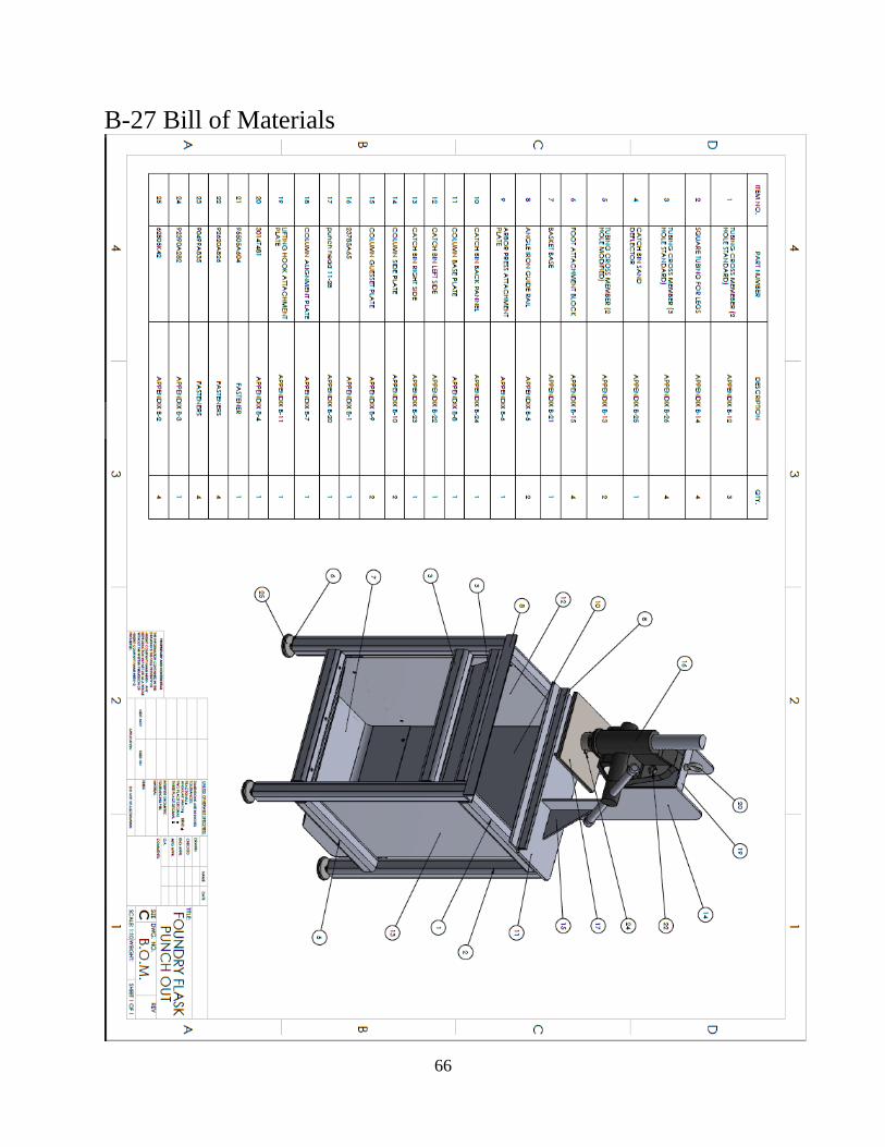
APPENDIX E – Schedule Gantt Chart The Gantt chart below showcases the tasks, time periods, and number of hours that went
into completing specific tasks relating the this project. The initial portion of this chart relates to
the proposal and engineering work that went into the design and documentation of the project.
Here is where all the engineering analysis was done as well as all the design work. The tasks for
these portions were created as the project progressed. Estimation for the time of completion was
created before each task was performed and documented when finished. Overall the estimated
time for the project came very near the actual documented time. One reason the estimated time is
close to the actual is due to the designers use and knowledge of Solidworks and the time it takes
to design and document parts.
The second part of the Gantt chart details the construction phase of the project. Due to
prior fabrication experience of the builder it was easy to assign tasks knowing what processes
needed to be done and the approximate time the processes took. As it can be seen most of the
estimates for time of completion were generous in the amount of time they designated. The
material for the project arrived later than expected so the project started nearly a week behind
schedule. However due to the manufacturability of the project most tasks took less time than
expected. This was good for getting the project back on schedule. Ample time was spent
fabricating and machining the project once material arrived. As it can be seen in the attached
Gantt chart 90% of the project was completed in a 10 day period (1/20/2018 – 2/1/2018). Despite
the arbor press is still being in transit, expected to arrive the week of 3/12/2018, the project has
been nearly complete sense 2/7/2018. This is almost a month ahead of the assigned due date for
the completed senior project.

69
70

71

72

73
Appendix F – Material Record
Haskins Steel order

74
McMaster Carr order

75
Appendix G – Testing Data
Test 1- Flask Rail Deflection
By following the listed test produce a deflection value of .0020 inches was acquired. The test
was preformed 3 times and the same result was consistently repeated. The predicted deflection
value was .0012 inches. This leaves the actual value .0008 inches over the predicted. However,
the deflection requirement for this project was to be less than .005 inches when loaded to 2000
lbf. This parameter was achieved.
Test 2- Column Deflection

76
By following the listed test produce a deflection value of .063”. This is .049” larger than the
predicted value but does not include the addition of the angle created by the baseplate flexing
upward. The baseplate flexed upward .008 inches.
Test 3 - Sand Removal
The target sand removal value for the Foundry Flask Punch-Out is 90%. To test this value 4
12"x14" flasks were used. By weighing the flasks filled with sand before and after punch-out as
well as accounting for the weight of the flask test data for the sand removal rate was acquired.
The sand tear pattern tends to leave a clean square on top of the flask with a tapper that leads to

77
the wall of the flask quickly. The remaining sand is no longer under compression and can be
easily removed from the flask by shaking or pushing on the flask or sand manually.
Test 4 – User Force Required
The user force test was a success. In the requirements for this project it was stated that a user
should not have to exert more than 50 lbf. to break out the molds. From this test it was found that
the user never had to use more than 30 lbf.

78
Appendix H – Data Evaluation Sheets Data for Test 2 (column deflection test) requires further evaluation to calculate to total column
deflection. This calculation is done below.
As it can be seen the .008” of upward flex in the baseplate causes the column to deflect an
additional .026” at the location to be read. Appendix A-3 predicts the column to deflect .014
inches. With the addition of the .026” the theoretical value of deflection would be .040”. This
makes the recorded value of .063” higher than predicted. My calculated value was 36.51% less
than predicted.
79
Appendix I – Testing Conclusion
The testing of the Foundry Flask Punch went as expected. Following the procedure for test 1
(flask rail deflection) results were obtained that were within 40% of the predicted value.
However these results were obtained with a dial indicator that is incremented in thousands of and
inch. The tested value was only .0008 thousands over the predicted value. Given that the dial can
only be read to the nearest .0005” it begs the question if the results would have been closer to the
predicted value if more precise measuring equipment was used.
The second test of this project was testing the columns deflection. In this test there was an issue
of the baseplate flexing along with the column. This added small angle to the column in addition
to its deflection. The result of this was a defection value that was .049” larger than expected. In
appendix H the small angle was accounted for and gave a result that was within 36.51% of the
predicted value. There are several factors that could have caused this. Many of these factors
retain the more complicated flexure of the baseplate than calculated. The straightness of the
column and the uniformity of the load are other factors that should be accounted for.
The third test of this projected tested the sand removal rate of the Foundry Flask Punch-Out
Machine. This test was done according to its procedure. The results of this test were satisfactory.
In the requirements of this project it was stated that this machine must remove at least 90% of
sands with a single operation. The testing shows that this criteria was on average exceeded with
an average of 92% removal across four 12”x14” flasks. One flask had a removal rate that was
slightly less than 90%. This could be due to the sand moisture content, compaction rate, or
misalignment during testing.
The fourth and final test that was performed was a user force test. This test was done in
conjunction with test 3 on the four 12”x14” flasks. The requirement for this machine was that a
user should not have to exert more than 50lbf. when operating this machine. To measure this a
simple handheld scale was used and the maximum force during the punch-out cycle was
observed. During this test it was made positive that the handheld scale was oriented within 5
degrees of perpendicularity to ensure an accurate measurement.

80
Appendix J – Resume
Nolan Stockman
2005 West Clearview Drive, Ellensburg, WA, 98926 I [email protected] I 206-817-6154
EDUCATION
▪ Central Washington University, Ellensburg Washington
o Pursuing a Bachelor of Science Degree in Mechanical Engineering Technology
o GPA: 3.828
o Class Standing: Senior (estimated graduation, June 2018)
o American Foundry Society (AFS) Member
▪ Bainbridge High School, Bainbridge Island Washington – Class of 2014
o High School Diploma
o GPA: 3.67
o Nation Honors Society
SKILLS AND QUALIFICATIONS
▪ Design for manufacturing
▪ Foundry work and systems management
▪ Solid Works (CSWA certification)
▪ Fabrication and welding
▪ MS Office Suite (Word, Excel, Power Point, Outlook)
▪ CNC & manual machining
▪ Strong leadership and critical thinking
▪ Hands on, motivated, ready to contribute and learn
WORK EXPERIENCE
▪ D&L Foundry – Moses Lake, WA (internship, Summer 2017)
o Equipment design
o Quality assurance
o Estimating
▪ Central Washington University Lab Technician – Ellensburg, WA (Fall 2016 – Present)
o Lab improvement, maintenance, and Preparation
o Project design and building
o Lab T.A.
▪ North Star Casteel – Seattle, WA (Internship, Summer 2016)
o Process improvement
o Equipment design, building, and application
o Industrial equipment experience
▪ Bainbridge Island Park District- Bainbridge Island, WA (Summer 2015)
o Park improvement and maintenance
▪ Bainbridge Athletic Club- Bainbridge Island, WA (2011-2014)
o Tennis Racket Stringer
o Building maintenance