Foundations Substructure Drainage Superstructure – … · Superstructure – Walls 10 ... upon...
32
Basic House-Building Series : Module 1 HB1126 11/03 1 Foundations 2 Substructure 5 Drainage 8 Superstructure – Walls 10 Superstructure – Floors 15 Superstructure – Roofs 16 Roof Coverings 19 Carcassing/First Fix 22 Plastering and Dry-Lining 26 Second Fix – Final Fix 27 Finishes 29 External Works 30 Index 31 CONTENTS
Transcript of Foundations Substructure Drainage Superstructure – … · Superstructure – Walls 10 ... upon...
Basic House-Building Series : Module 1 HB1126 11/03 1
Foundations 2
Substructure 5
Drainage 8
Superstructure – Walls 10
Superstructure – Floors 15
Superstructure – Roofs 16
Roof Coverings 19
Carcassing/First Fix 22
Plastering and Dry-Lining 26
Second Fix – Final Fix 27
Finishes 29
External Works 30
Index 31
C O N T E N T S

FoundationsThe type of foundation used on any particular site is dependentupon the ground conditions of that site and the design of thefoundations is based upon the results of a site and groundinvestigation. It is quite possible, on a site with variable groundconditions, to have several different types of foundation.
With all types of foundation, the purpose is to transfer theweight of the dwelling to the ground in such a way as tominimise the risk of any future movement of the structure.
Throughout the following descriptions the word 'soil' is used todenote the different types of ground encountered commonly inthe UK e.g. clay, sand, gravel, chalk, rock etc.
On clay soils, near trees, it may be necessary to excavatedeeper than would normally be the case due to the potentialmovement of the clay due to changes in its moisture content.In dry periods trees may draw moisture from the clay causingit to shrink resulting in subsidence of the foundation. Wheretrees are removed, the reverse can be the case. The clay canrecover moisture and swell causing heave to the foundations.
Notes:
Site stripThis is the process by which all vegetation and organic soil is stripped from the area where the dwellings will be sited. All vegetation and organic material should be removed fromunder the dwelling to prevent the material rotting causing apossible build up of methane gas below the ground floor.
Notes:
2 Basic House-Building Series : Module 1
F O U N D A T I O N S S T A G E 1

Basic House-Building Series : Module 1 3
Strip foundationThis is the simplest form of foundation and consists of a stripof concrete, usually approximately 225mm thick, laid in thebottom of a relatively shallow trench excavation. This type offoundation is used where the type of soil which will supportthe weight of the dwelling is near the surface of the ground.
Notes:
Trench fill foundationsThis is a relatively narrow trench excavation filled with agreater thickness of concrete. It is used where the type of soilwhich will support the weight of the dwelling is deeper (up toapproximately 3 to 4 metres) or where the dwelling is to besituated near trees on a clay soil.
Notes:
S T A G E 1 F O U N D A T I O N S

PilesA piled foundation is used where the soil that will support thedwelling is deep (usually in excess of 4 metres). Commonlythey are formed by two methods. Firstly by drilling holes to aspecified depth, inserting a hollow shell, and filling the shellwith concrete and steel reinforcement.
A second method is to use pre-cast concrete piles driventhrough the poor bearing ground into the soil that will supportthe dwelling.
Piles are inserted under all the load-bearing walls of thedwelling, usually at approximately 3 metre spacing. Aroundthe top of the piles a reinforced concrete ring beam is castupon which the walls of the dwelling are built.
Notes:
RaftA raft is a one piece, reinforced concrete slab which is designedto spread the load of the dwelling over a greater area of groundand minimise the risk of uneven settlement where soft soilconditions exist. An example of such a soil type is silty claycommonly found in the bottom of valleys.
Additionally, raft foundations are frequently used in areas ofdeep mining where there is risk of surface settlement due tothe collapse of deep mine workings. The raft foundation allowsa small amount of settlement without causing any damage tothe dwelling.
Notes:
4 Basic House-Building Series : Module 1
ring beam
pile
F O U N D A T I O N S S T A G E 1

Basic House-Building Series : Module 1 5
Substructure is the term used for the work required belowground to raise the dwelling construction from the foundationsto ground floor level. This section also includes the differenttypes of ground floor construction.
Walls below groundThe walls of the dwelling below ground can be of either solidor cavity construction. For both methods concrete blocks areusually used. If built of cavity construction, the cavity must befilled with concrete to just below ground level to prevent thecavity collapsing due to pressure from backfill. If built of trenchblocks (large blocks forming the full width of the cavity wall)separate concrete cavity fill is obviously not required. This canspeed up the construction process.
Notes:
Ground bearing floorThe simplest form of ground floor is an un-reinforced concrete slab which rests on and is supported by compactedhardcore laid on the ground below. This type of floor is costeffective where good ground conditions exist. There is,however, a risk of settlement of the floor if the hardcore is not properly compacted. This risk increases with greaterdepths of hardcore and NHBC recommends a maximum depth of 600mm of hardcore fill.
Where greater than 600 mm of hardcore would be requiredsome form of suspended floor should be used.
Notes:
concretecavity fill
foundation
DPC(dampproofcourse)
DPM (damp proofmembrane)
S T A G E 2 S U B S T R U C T U R E

Beam and block suspendedground floorA proprietary system of reinforced concrete beams designedto span between the load-bearing walls of the dwelling.Concrete blocks are placed between the beams to form thefloor. With this form of construction a void is left beneath thefloor beams. This void should be ventilated by the provision of air bricks in the external walls. This reduces the risk ofcondensation causing dampness in the floor and prevents thepotential build up of gas within the void. As this is a ‘dry’ formof construction, there is no reliance on the weather forconstruction to continue.
Notes:
Reinforced concrete suspendedground floorAn in-situ reinforced concrete floor which is supported by theload-bearing walls of the dwelling. Backfill within the dwellingprovides temporary support to the concrete while it cures.
Notes:
6 Basic House-Building Series : Module 1
DPM
reinforcement
S U B S T R U C T U R E S T A G E 2

Basic House-Building Series : Module 1 7
Timber suspended ground floorThis is the traditional method of ground floor construction withtimber joists spanning between the load-bearing walls of thedwelling. Ventilation is provided, by airbricks in the externalwalls, to the void below the floor to reduce the risk of decay inthe timber joists. To further minimise the risk of dampness inthe void, the surface of the ground is covered by a layer ofoversite concrete. To prevent ponding of water under the timberfloor, the oversite concrete should be at ground level or above.
Notes:
Damp Proof Membrane (DPM)Sheet material, generally of polythene, laid under solid concretefloors to prevent moisture rising from the fill below causingdampness in the floor construction.
Notes:
airbrick
oversiteconcrete
S T A G E 2 S U B S T R U C T U R E

Underground drainageModern drainage systems usually have separate networks ofdrains for the disposal of foul water and rainwater. Foul wateris discharged into sewers leading to treatment works whereasrainwater is usually discharged to a stream or river or,alternatively, a soakaway.
Modern materials for drainage systems are either plastic orclay. Both types of drain pipes are connected using plasticcollars with rubber seals to ensure watertightness. Plastic pipesare the most common being easier to handle and, as they aremanufactured in lengths of 5 metres, require less joints. Alldrainage systems are laid to a fall to ensure adequate flow and reduce the risk of blockages.
All drain runs should be accessible for rodding if blockagesoccur. The type of access provided is usually determined by thedepth of the drain run.
If drains run across an area where a future extension is likely,the drains must be kept 5 metres away from that elevation ofthe building.
Notes:
Access and inspection chambersDepending upon the materials used for the drain runs these areusually formed of plastic or clay. The diameter of the chamberis determined by the depth of the drain run. The simple rule isthat the deeper the drain run the larger the chamber in orderto allow effective access.
Notes:
8 Basic House-Building Series : Module 1
access chamber
inspection chamber
D R A I N A G E S T A G E 3

Basic House-Building Series : Module 1 9
ManholeWhere drains are more than 1 metre deep. Manholes are usuallyformed with a concrete base and pre-cast concrete rings to formthe chamber. Step irons are provided in the wall of the manholeto allow access.
Notes:
GulleyThe means by which foul water (other than from WCs) isdischarged to the foul drain. The gulley contains a water trapwhich prevents smells and gases escaping from the drain.
Notes:
Soil stackDischarge from WCs (usually by a soil stack) is via a directconnection into the foul drain. The trap on the WC itselfprevents smells and gases escaping into the house. All otherconnections into the soil stack (bath, wash hand basin, showers,bidet and kitchen sinks) also have traps for the same purpose.
The soil pipe is open at the top to allow ventilation to preventthe build-up of explosive gases in the drainage system and toprevent syphonage. If soil pipes terminate within the dwellingthen an air admittance valve is provided to allow air into thesystem to prevent syphonage. Obviously, in this location,ventilation of the drain is undesirable as it would allow smellsinto the dwelling.
Notes:
manhole
S T A G E 3 D R A I N A G E

This stage includes the construction of the shell of thehouse and internal load-bearing walls.
Cavity wallsThe external walls of most new dwellings are of cavityconstruction with an outer leaf of facing brick and an innerleaf of concrete blockwork separated and tied together withwall ties. The outer leaf of facing brickwork is porous, allowingdriving rain to penetrate to the inside of the bricks. The purposeof the cavity is to prevent the moisture crossing to the innerleaf and causing dampness within the dwelling.
Wall ties are made from stainless steel or plastics and have a drip which is positioned centrally in the cavity to preventmoisture crossing the tie to the inner leaf.
Notes:
Facing bricks are usually of fired clay and can be of varyingqualities relating to their frost resistance and sulphate content.The best quality bricks, designated FL, are fully frost resistantand suitable for more severe exposure areas.
The inner leaf can be of various block types depending upon thespecification for the external walls of the dwelling. In all casesthe design must comply with minimum Building Regulationrequirements for thermal insulation. This can be achieved bybuilding with a clear cavity and using the appropriate thermalblocks for the inner leaf. These are commonly AutoclavedAerated Concrete Blocks.
Cavity insulationAn alternative to building with a clear cavity is to use someform of cavity insulation. This can be where the cavity is fullyfilled with insulation, either at the time of construction orblown into the cavity afterwards. Cavity insulation materialsare designed to prevent moisture crossing the insulation tothe inner leaf.
Notes:
10 Basic House-Building Series : Module 1
S U P E R S T R U C T U R E – W A L L S S T A G E 4
wall tie
full fill cavityinsulation
Basic House-Building Series : Module 1 11
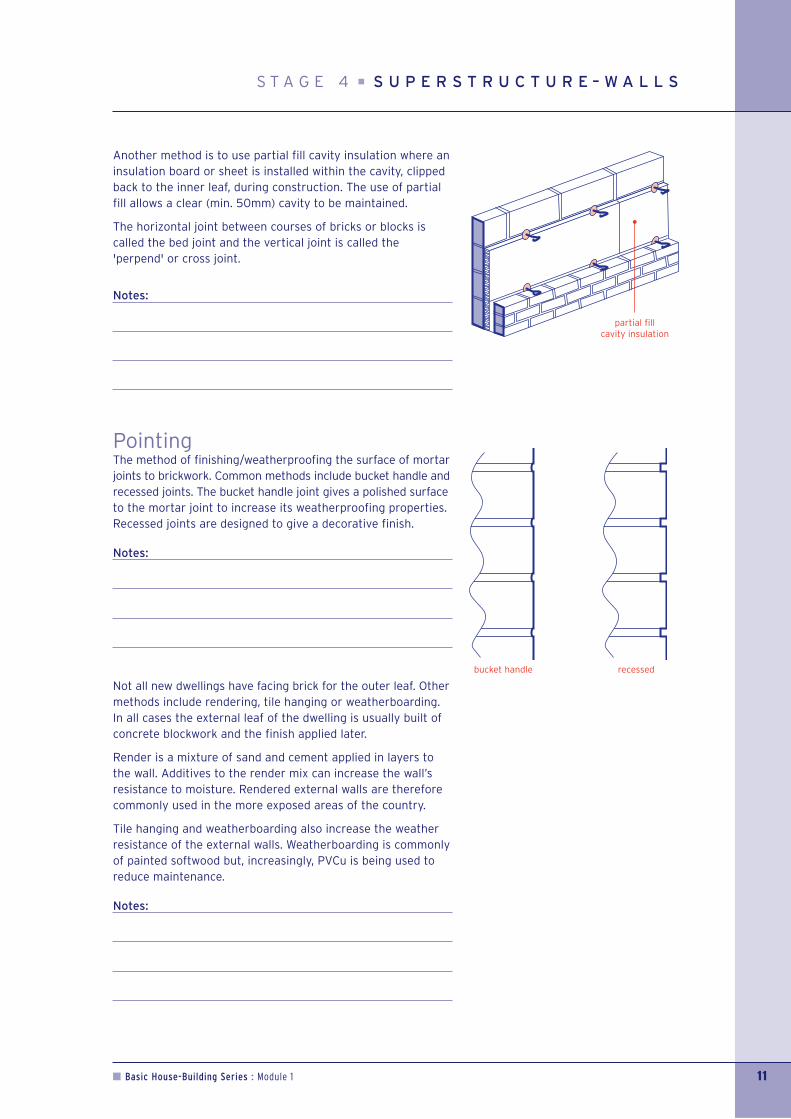
Another method is to use partial fill cavity insulation where aninsulation board or sheet is installed within the cavity, clippedback to the inner leaf, during construction. The use of partialfill allows a clear (min. 50mm) cavity to be maintained.
The horizontal joint between courses of bricks or blocks iscalled the bed joint and the vertical joint is called the'perpend' or cross joint.
Notes:
PointingThe method of finishing/weatherproofing the surface of mortarjoints to brickwork. Common methods include bucket handle andrecessed joints. The bucket handle joint gives a polished surfaceto the mortar joint to increase its weatherproofing properties.Recessed joints are designed to give a decorative finish.
Notes:
Not all new dwellings have facing brick for the outer leaf. Othermethods include rendering, tile hanging or weatherboarding.In all cases the external leaf of the dwelling is usually built ofconcrete blockwork and the finish applied later.
Render is a mixture of sand and cement applied in layers tothe wall. Additives to the render mix can increase the wall’sresistance to moisture. Rendered external walls are thereforecommonly used in the more exposed areas of the country.
Tile hanging and weatherboarding also increase the weatherresistance of the external walls. Weatherboarding is commonlyof painted softwood but, increasingly, PVCu is being used toreduce maintenance.
Notes:
bucket handle recessed
S T A G E 4 S U P E R S T R U C T U R E – W A L L S
partial fill cavity insulation

Damp Proof Course (DPC)A waterproof barrier, usually of plastic material, built in to thewalls of the dwelling just above ground level to prevent moisturerising from the ground into the dwelling.
Notes:
WindowsTraditionally of softwood or hardwood but increasingly PVCu is being used to reduce maintenance. All new dwellings aredouble glazed to meet the thermal insulation requirements ofthe Building Regulations.
Notes:
External doorsTraditionally of softwood or hardwood material. Increasingly,insulated metal doors are being used to provide additionalsecurity and reduce the risk of warping of the external door.Alternatively, PVCu can also be used.
Notes:
LintelsInstalled to provide support to brickwork and blockwork over anopening in a masonry wall. Can be of concrete or steel with themost common being combined steel lintels providing supportto both leaves of the external cavity wall. Combined lintels canincorporate a cavity tray to guide moisture within the cavity tothe outside.
Notes:
12 Basic House-Building Series : Module 1
concrete lintel
S U P E R S T R U C T U R E – W A L L S S T A G E 4
sealant
sealant
Basic House-Building Series : Module 1 13
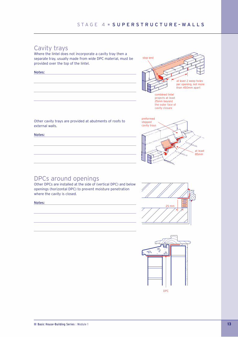
Cavity traysWhere the lintel does not incorporate a cavity tray then aseparate tray, usually made from wide DPC material, must beprovided over the top of the lintel.
Notes:
Other cavity trays are provided at abutments of roofs toexternal walls.
Notes:
DPCs around openingsOther DPCs are installed at the side of (vertical DPC) and belowopenings (horizontal DPC) to prevent moisture penetrationwhere the cavity is closed.
Notes:
at least 2 weep holesper opening, not morethan 450mm apart
combined lintelprojects at least25mm beyond the outer face ofcavity closure
S T A G E 4 S U P E R S T R U C T U R E – W A L L S
DPC
stop end
at least85mm
preformed steppedcavity trays
Separating wallWalls between attached dwellings (terraced, semi-detachedhouses or flats) are called separating walls or commonly 'partywalls'. Constructed of dense concrete block (or sometimes brick)they are designed in accordance with Building Regulations, to provide adequate sound insulation and fire resistancebetween dwellings.
Notes:
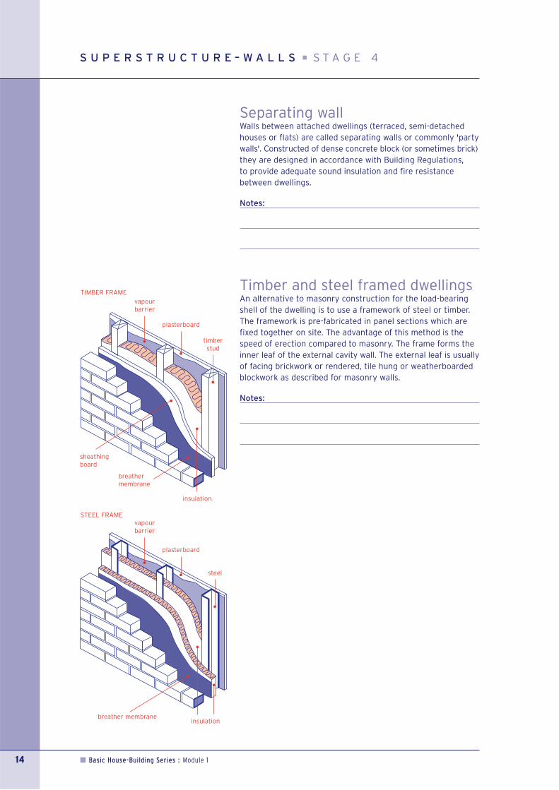
Timber and steel framed dwellingsAn alternative to masonry construction for the load-bearingshell of the dwelling is to use a framework of steel or timber.The framework is pre-fabricated in panel sections which arefixed together on site. The advantage of this method is thespeed of erection compared to masonry. The frame forms theinner leaf of the external cavity wall. The external leaf is usuallyof facing brickwork or rendered, tile hung or weatherboardedblockwork as described for masonry walls.
Notes:
14 Basic House-Building Series : Module 1
breathermembrane
STEEL FRAME
S U P E R S T R U C T U R E – W A L L S S T A G E 4
insulation
vapourbarrier
TIMBER FRAME
plasterboard
timberstud
vapourbarrier
plasterboard
steel
sheathingboard
insulation breather membrane

Basic House-Building Series : Module 1 15
The intermediate floors within dwellings.
Timber floorsIn two storey houses, most commonly formed with timber orcomposite joists spanning between the external and internalload-bearing walls of the dwelling.
Notes:
TrimmerThis is the term used for the joists which support the joistswhich have been 'trimmed' to form the opening for thestaircase. The most common method of connection for the floorjoists to the trimmers is by metal joist hangers.
Notes:
Concrete floorsIn the construction of flats the intermediate floors are most commonly formed with pre-cast reinforced concreteplanks again spanning between the external and internal load-bearing walls of the dwelling. The planks are designed tosuit particular dwelling types with pre-formed openings forstaircases and services.
Notes:
Lateral restraint strapGalvanised steel straps fixed to the floor structure and built into gable and separating walls to provide additional stability tothese walls (also provided at roof level).
Notes:
S T A G E 5 S U P E R S T R U C T U R E – F L O O R S
trimmer joists
noggin
lateralrestaint strap

Trussed rafters (roof trusses)Prefabricated timber or metal frames supplied by specialistmanufacturers to engineering design specifications. They areusually only supported on the external walls of the dwelling.This removes the need for internal load-bearing walls to supportthe roof giving freedom of room layout design. An additionaladvantage is that, as most of the roof frame is prefabricated,the process of roof frame construction on site is quicker thanwith traditional roof construction. One perceived disadvantageto the homeowner is that there is reduced space for storage inthe roof space.
Note: Heavy or large quantities of material should not bestored in the roof space.
Notes:
WallplateThe trussed rafters are fixed to the wallplate which is a timberbeam bedded on cement mortar on top of the load-bearingwalls. Wallplates are anchored to the walls by holding downstraps. The straps are generally made of galvanised steel andare shaped to hook over the wall plate and be fixed to the wall below.
Notes:
BracingTimber boards which are fixed to the trusses within the roofspace. The exact positions are determined by the design andspan of the roof trusses. Their purpose is to prevent the trussesdistorting under the load of the roof covering and possiblesnow loading. In addition they also help provide resistanceagainst wind pressure.
Notes:
16 Basic House-Building Series : Module 1
S U P E R S T R U C T U R E – R O O F S S T A G E 6
bracing
wall plate

Basic House-Building Series : Module 1 17
Lateral restraint strapGalvanised steel straps fixed to the trussed rafters and built intothe gable and separating walls to provide additional stability tothese walls (also provided at intermediate floor levels).
Notes:
VergeThe verge is the term used for the edge of the roof whichprojects beyond a gable wall. This projection providesweatherproofing protection to the top of the gable wall. The undercloak is the term for the board used to support the projecting tiles.
Notes:
Barge boardBarge boards are the sloping boards sometimes used beneathverges. They are traditional of timber but increasingly madefrom PVCu to reduce maintenance. They can be either fixedflush to the wall or in a box construction with a soffit beneath.
Notes:
S T A G E 6 S U P E R S T R U C T U R E – R O O F S
lateralrestaint strap
barge board

EavesThe term for the bottom of a pitched roof. The most commonform of construction is an eaves box formed by a fascia boardand a soffit board.
Notes:
FasciaTraditionally timber boards fixed to the projecting foot of thetrussed rafter. Again, increasingly made from PVCu to reducemaintenance. Rainwater gutters are normally fixed to thefascia board.
Notes:
SoffitThe board forming the underside of the eaves box. Traditionallyformed from plywood or other composite board material butagain increasingly made from PVCu to reduce maintenance.
Soffit ventilationCondensation can be caused if warm moist air from the dwellingrises up through the insulation and is trapped within the coldroof space. Slots or holes are therefore cut into the soffit boardto allow cross ventilation of the roof space. The slots or holeshave a mesh covering to stop birds and insects gaining access.
To be effective, the ventilation must be on opposite sides of theroof. With other than normal roof shapes additional methodsmay be required to provide adequate cross ventilation.
Warm roof designs have no cold space and so do not requireany ventilation.
Notes:
Ventilation spacerA timber or proprietary baffle, fixed between the roof trusses,so that ceiling insulation can be installed over the wall platewithout blocking the ventilation.
Notes:
18 Basic House-Building Series : Module 1
S U P E R S T R U C T U R E – R O O F S S T A G E 6
sofit
spacer/baffle
insulation
ventilation
fascia
Basic House-Building Series : Module 1 19
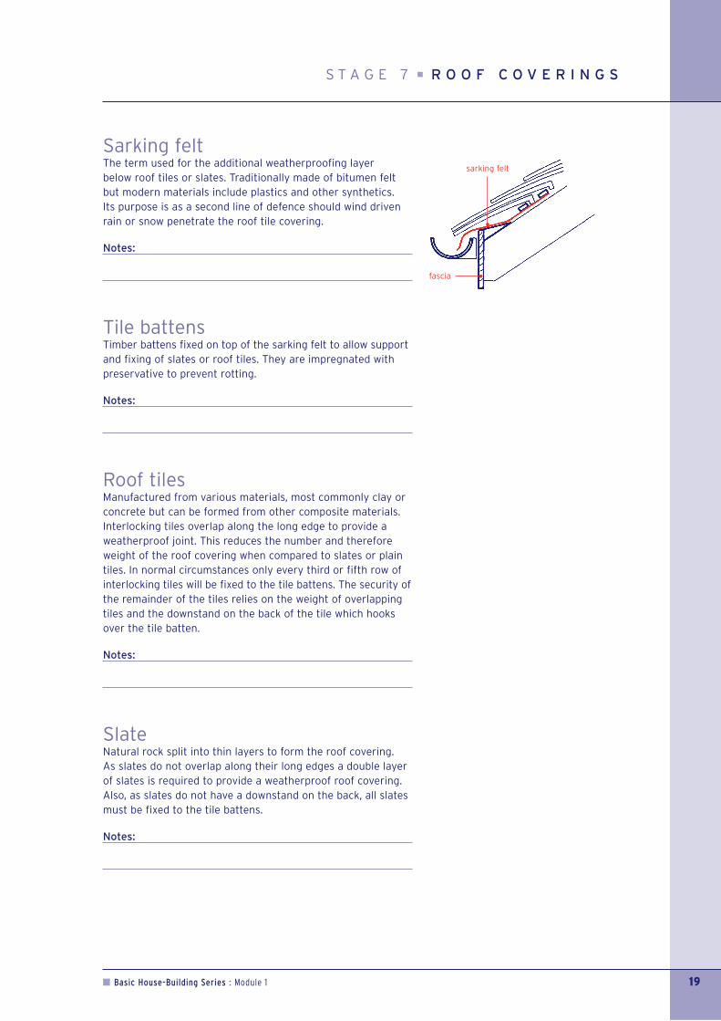
Sarking feltThe term used for the additional weatherproofing layer below roof tiles or slates. Traditionally made of bitumen feltbut modern materials include plastics and other synthetics. Its purpose is as a second line of defence should wind drivenrain or snow penetrate the roof tile covering.
Notes:
Tile battensTimber battens fixed on top of the sarking felt to allow supportand fixing of slates or roof tiles. They are impregnated withpreservative to prevent rotting.
Notes:
Roof tilesManufactured from various materials, most commonly clay orconcrete but can be formed from other composite materials.Interlocking tiles overlap along the long edge to provide aweatherproof joint. This reduces the number and thereforeweight of the roof covering when compared to slates or plaintiles. In normal circumstances only every third or fifth row ofinterlocking tiles will be fixed to the tile battens. The security ofthe remainder of the tiles relies on the weight of overlappingtiles and the downstand on the back of the tile which hooksover the tile batten.
Notes:
SlateNatural rock split into thin layers to form the roof covering. As slates do not overlap along their long edges a double layerof slates is required to provide a weatherproof roof covering.Also, as slates do not have a downstand on the back, all slatesmust be fixed to the tile battens.
Notes:
S T A G E 7 R O O F C O V E R I N G S
sarking felt
fascia

FlashingA junction between a roof and a wall is weatherproofed by theprovision of a suitable flashing. This is usually made from leador other non-ferrous metal positioned over the roof tiles orslates with an upstand fixed into the wall.
Notes:
ValleyLead, supported by a timber board, is the traditional materialused to weatherproof valleys. Increasingly, modern materialssuch as glass reinforced plastic (GRP) are used as they areeasier to handle and are more stable than lead.
Notes:
20 Basic House-Building Series : Module 1
R O O F C O V E R I N G S S T A G E 7
flashing
valley

Basic House-Building Series : Module 1 21
Ridge and hipWeatherproofing to ridges and hips is achieved by the fixing of ridge or hip tiles to cover the cut or top edge of the roofingtile, traditionally simply bedded on cement mortar. Hip tilesare prevented from sliding down the roof by a decorative hipiron fixed at eaves level. An alternative method of fixing ridgeor hip tiles is to use a proprietary mechanical system whichprovides positive attachment of the tiles to the roof frame.
Notes:
VergeThe traditional method of finishing the sloping edge of the roofis to use cement mortar to 'point-up' the gap between the tilesand the undercloak, providing a weatherproof and pest prooffinish. Alternative methods include the use of special verge tilesor proprietary, plastic verge covers which directly seal the gapand avoid the need for mortar pointing.
Notes:
Flat roofsLittle used in modern house building. The term 'flat roof' isactually incorrect as flat roofs are laid to falls to allow rainwaterto drain to the gutter at the side of the roof. The roof is fullyboarded to provide support to the weatherproof covering whichis usually of one or more layers of bitumen based felt fixed withbitumen adhesive. Flat roofs are usually covered by a layer ofwhite stone chippings to reflect heat and protect the felt frombeing affected by sunlight.
Notes:
S T A G E 7 R O O F C O V E R I N G S

Carcassing or first fix are the terms generally used to cover allthe work carried out internally prior to plastering or dry-lining.The trades involved are plumber, electrician and carpenter.
Electrician – wiring carcassAll the main electric cable runs for power, lighting, centralheating and alarm systems. The positioning of the cables islimited to safe zones so purchasers can be aware of thelocation of the wires after occupation.
The safe zones for cables in walls are:
• Horizontally or vertical from any switch or socket
• Within 150mm of internal corners of walls
• 150mm below ceilings.
Within intermediate floors, wiring runs are positioned throughholes drilled on the centreline of the floor joists to preventdamage when floor boards or plasterboard ceilings are nailedto the joists.
Notes:
Plumber – plumbing carcassAll the main pipe runs for hot and cold water services andcentral heating. Traditionally copper pipes are used withsoldered joints. One drawback of copper is that it expands and contracts substantially with temperature changes leadingto creaking and groaning as systems heat up or cool down. A modern variation is plastic pipes which reduce this risk of noise.
Within intermediate floors, pipe runs are positioned in notchescut into the top of the floor joists.
Additionally, waste pipes and internal soil stack(s) are fitted atthis time.
Notes:
22 Basic House-Building Series : Module 1
C A R C A S S I N G / F I R S T F I X S T A G E 8
in shaded zone150mm wide
vertically or horizontallyto switch or outlet
LOCATION OF CABLES WITHOUT SPECIAL PROTECTION

Basic House-Building Series : Module 1 23
CarpenterTimber struttingThis is fixed between the floor joists to prevent twisting. The strutting can be herringbone or solid. An alternative is to provide proprietary metal straps.
Notes:
NoggingsSmall pieces of timber fixed between the floor joists tosupport the edges of the floor boards above or plasterboardceilings below.
Notes:
FlooringTraditionally of tongue and groove softwood boards but nownearly always of tongue and groove chipboard sheets. Softwoodboarding is prone to shrinkage and ‘cupping’ after laying as it dries out. Modern chipboard flooring gives a very flat andstable floor finish and is moisture resistant to prevent damageduring the construction process or from spillage after thehouse is occupied.
Concrete ground floors are sometimes finished with tongue andgrooved chipboard flooring on battens or polystyrene insulationboards. This provides thermal insulation to the floor, gives asmooth and level finish and also allows some movement to givea little ‘spring’ in the floor.
Notes:
S T A G E 8 C A R C A S S I N G / F I R S T F I X
herringbonestrutting
blocking
solid strutting
noggings
joist or nogging
Door liningsThese are the internal door frames and are traditionally ofsoftwood. Increasingly, other materials such as medium densityfibreboard (MDF) are being used. The advantages of this materialover natural softwood are that it does not shrink or twist ondrying out and gives a very smooth finish.
Notes:
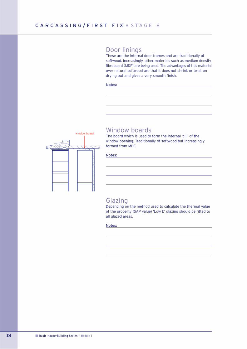
Window boardsThe board which is used to form the internal ‘cill’ of thewindow opening. Traditionally of softwood but increasinglyformed from MDF.
Notes:
GlazingDepending on the method used to calculate the thermal valueof the property (SAP value) ‘Low E’ glazing should be fitted toall glazed areas.
Notes:
24 Basic House-Building Series : Module 1
C A R C A S S I N G / F I R S T F I X S T A G E 8
window board

Basic House-Building Series : Module 1 25
PartitionsNon load-bearing partitions are commonly of vertical timberstuds with plasterboard to each side or a proprietarypartitioning system. Most of the proprietary systems includetimber or metal vertical struts with a composite boardmaterial between.
Partition walls may also have insulation quilt in the centre toreduce the amount of sound passing through the wall, asrequired by the Building Regulations.
Notes:
StaircaseTraditionally of softwood but, increasingly, MDF and othercomposite board materials are being used to minimise problemscaused by shrinkage.
Notes:
S T A G E 8 C A R C A S S I N G / F I R S T F I X
stud
possible soundreducing quilt
plasterboard
newel post
handrail
spindle
nosing
riser
going/tread
string

Wet plasterThe traditional method of internal finishing to masonry walls. Can be of various mixed materials includingsand and cement but more commonly, in modern times, of premixed gypsum plaster basecoat with aharder topcoat of similar material to give a smooth finish. As this is a wet process requiring a substantialvolume of water, the dwelling takes a long time to dry out and is more prone to shrinkage cracking andcondensation problems in its early life.
Notes:
Dry liningThis is, by far, the most common method of finishing the internal walls in modern use. Plasterboard is fixedto the masonry walls by bedding the boards on adhesive plaster dabs and is fixed to timber partitions bygalvanised nails or screws.
True dry-lining relies on the surface of the plasterboard to provide the finished wall surface. Board edgesare taped, filled and sanded to provide a smooth, joint free surface.
An alternative method is, after taping and filling the joints, to skim the boards with a thin layer of hard plaster.
Notes:
CeilingsUsually of plasterboard, nailed or screwed to the underside of the intermediate floor or roof structure.The same finishes as for dry-lined walls can be used. One risk of a skimmed ceiling is that with the naturalmovement of the floor above, cracking to the ceiling can occur. The use of a decorative finish such asArtex can reduce the risk of this cracking as the Artex material is flexible, even when dry.
Notes:
Floor screedsConcrete floors are often finished with a layer of sand and cement screed. This is to give a level andsmooth finish to the concrete floor.
Notes:
26 Basic House-Building Series : Module 1
P L A S T E R I N G A N D D R Y - L I N I N G S T A G E 9
Basic House-Building Series : Module 1 27
The term used for all work to complete the internal fixturesand fittings prior to decoration. As with first fix the tradesinvolved are plumber, electrician and carpenter.
ElectricianThe electrician fits all the switches, socket outlets, lightingoutlets, smoke alarms, central heating controls, earth protectionand the consumer unit connected to the wiring carcass installedat first fix stage.
The Building Regulations now require, energy efficient lightfittings for any external lighting and a number of internal fittings(equal to one energy efficient light for every three rooms).
Notes:
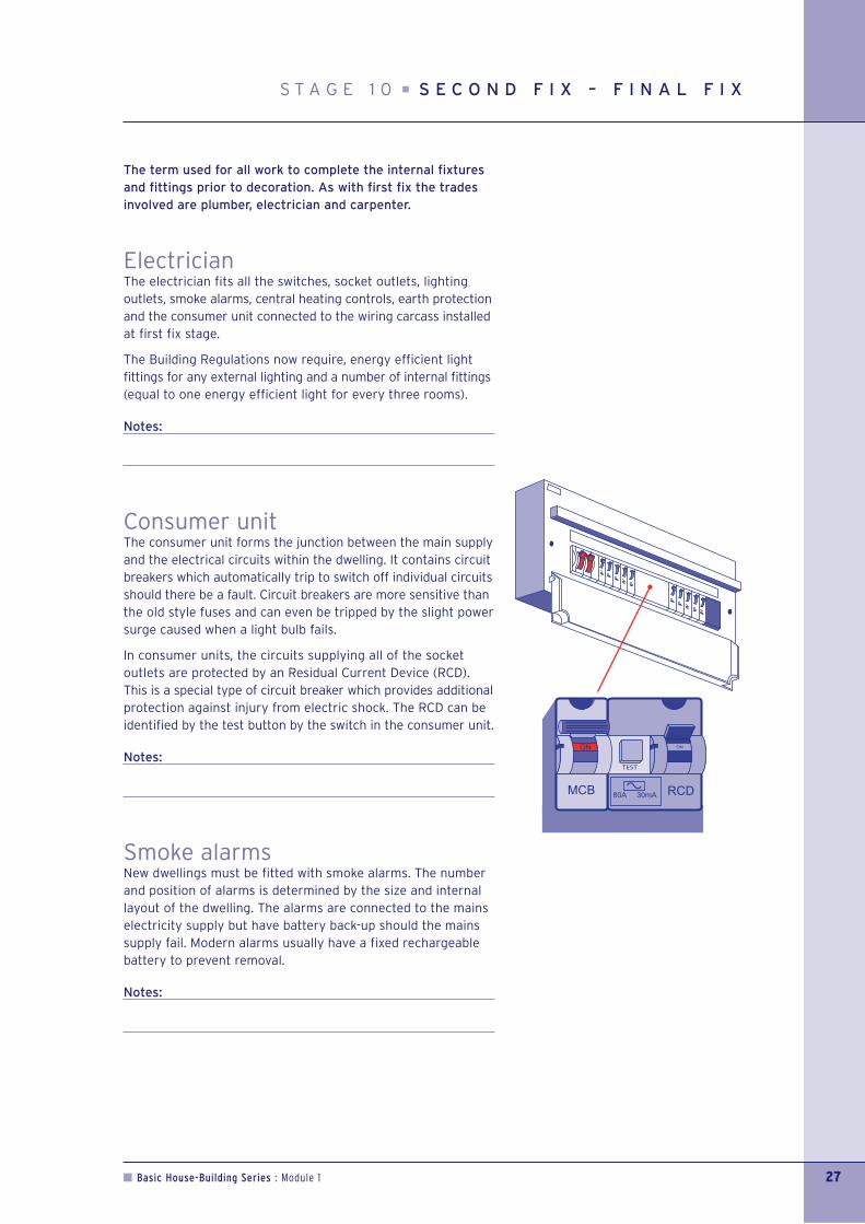
Consumer unitThe consumer unit forms the junction between the main supplyand the electrical circuits within the dwelling. It contains circuitbreakers which automatically trip to switch off individual circuitsshould there be a fault. Circuit breakers are more sensitive thanthe old style fuses and can even be tripped by the slight powersurge caused when a light bulb fails.
In consumer units, the circuits supplying all of the socketoutlets are protected by an Residual Current Device (RCD).This is a special type of circuit breaker which provides additionalprotection against injury from electric shock. The RCD can beidentified by the test button by the switch in the consumer unit.
Notes:
Smoke alarmsNew dwellings must be fitted with smoke alarms. The numberand position of alarms is determined by the size and internallayout of the dwelling. The alarms are connected to the mainselectricity supply but have battery back-up should the mainssupply fail. Modern alarms usually have a fixed rechargeablebattery to prevent removal.
Notes:
S T A G E 1 0 S E C O N D F I X – F I N A L F I X
Mechanical ventilationIt is a requirement of the Building Regulations that all kitchens,bathrooms and WCs are provided with mechanical ventilation.In kitchens this is usually achieved by the provision of a cookerhood, ducted to the outside.
Notes:
Carpenter/JoinerAt this stage the carpenter/joiner fits the kitchen units, internaldoors, finishing timber items such as skirting boards andarchitraves around doors. These are traditionally of softwoodor hardwood but, increasingly, MDF is being used due to itsstability and smooth finish.
Notes:
PlumberThe plumber fits all the sanitary ware - baths, wash hand basins,WCs , bidets and kitchen/utility room sinks including all traps,waste, and hot and cold water connections.
Additionally the central heating installation is completedincluding boiler, radiators, hot water cylinder and header tanks in the roof space (if fitted). There are many differenttypes of heating and hot water systems some of which do notrequire header tanks. Central heating systems are usuallyregulated by thermostats. These can be fitted to radiators tocontrol individual room temperatures or be room thermostatsto control the whole of the heating system or various zoneswithin the dwelling.
Notes:
Hearths and fluesIf either of these are provided by the builder, a Safety NoticePlate must now be fitted within the dwelling (e.g. next to theconsumer unit) giving details of the hearth and/or flue.
Notes:
S E C O N D F I X – F I N A L F I X S T A G E 1 0
28 Basic House-Building Series : Module 1
Basic House-Building Series : Module 1 29
FinishesInternal finishes to timber can be either paint or stain. It shouldbe noted that MDF should only be painted. Walls are normallyfinished with a water-based emulsion paint to allow drying-outof construction moisture within the dwelling. Drying out periodsvary depending upon the form of construction.
Other finishing items include:
• door furniture (letter plates, handles, latches, knockers etc.)
• installation of kitchen appliances (white goods)
• floor tiling or other covering.
Notes:
S T A G E 1 1 F I N I S H E S
External works is the term used for all work to complete thefinishes around the dwelling. This work includes the laying ofdrives and paths, boundary fences, free standing walls andretaining walls.
Drives and paths can be constructed using various materialssuch as coated macadam, brick pavers, paving slabs or concrete.
Notes:
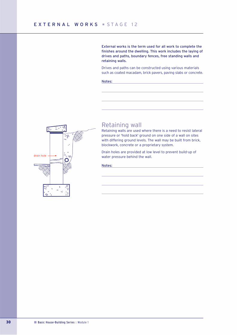
Retaining wallRetaining walls are used where there is a need to resist lateralpressure or 'hold back' ground on one side of a wall on siteswith differing ground levels. The wall may be built from brick,blockwork, concrete or a proprietary system.
Drain holes are provided at low level to prevent build-up ofwater pressure behind the wall.
Notes:
30 Basic House-Building Series : Module 1
E X T E R N A L W O R K S S T A G E 1 2
drain hole
Basic House-Building Series : Module 1 31
Access and inspection chambers 8
Barge board 17
Beam and block suspended ground floor 6
Bracing 16
Carpenter 23
Carpenter/joiner 28
Cavity insulation 10
Cavity trays 13
Cavity walls 10
Ceilings 26
Concrete floors 15
Consumer unit 27
Damp proof course 12
Damp proof course – around openings 13
Damp proof membrane 7
Door linings 24
Drainage 8
Dry lining 26
Eaves 18
Electrician 27
Electrician – wiring carcass 22
External doors 12
External works 30
Fascia 18
Finishes 29
Flat roofs 21
Flashing 20
Flooring 23
Floor screeds 26
Foundations 2
Glazing 24
Gulley 9
Ground bearing floor 5
Lateral restraint strap 15 & 17
Lintels 12
Manhole 9
Mechanical ventilation 28
Noggings 23
Partitions 25
Piles 4
Plumber 22 & 28
Plumber – plumbing carcass 22
Pointing 11
Raft 4
Reinforced concrete suspended ground floor 6
Retaining wall 30
Ridge & hip 21
Roof tiles 19
Sarking felt 19
Separating wall 14
Smoke alarms 27
Soffit 18
Soffit ventilation 18
Site strip 2
Slate 19
Staircase 25
Strip foundation 3
Tile battens 19
Timber floors 15
Timber and steel framed dwellings 14
Timber strutting 23
Timber suspended ground floor 7
Trench fill foundation 3
Trimmer 15
Trussed rafters (roof trusses) 16
Valley 20
Ventilation spacer 18
Verge 17 & 21
Walls below ground 5
Wallplate 16
Wet plaster 26
Windows 12
Window boards 24
I N D E X

Notes:
32 Basic House-Building Series : Module 1