![Soil Transmitted Helminthiasis [Parasitology]](https://static.fdocuments.us/doc/165x107/56d6bf191a28ab301694e16d/soil-transmitted-helminthiasis-parasitology.jpg)
FOUNDATIONS - ct.upt.ro C1.pdf · § 1.1 Introduction The foundation soil represents the shallow...
18
FOUNDATIONS Prof.dr.ing Adrian CIUTINA Universitatea Politehnica Timişoara Facultatea de Construcţii Departamentul de Căi de Comunicație Terestre, Fundații și Cadastru - CURS 1 - Introduction Basis of Design
Transcript of FOUNDATIONS - ct.upt.ro C1.pdf · § 1.1 Introduction The foundation soil represents the shallow...

FOUNDATIONS
Prof.dr.ing Adrian CIUTINA
Universitatea Politehnica Timişoara
Facultatea de Construcţii
Departamentul de Căi de Comunicație Terestre, Fundații și Cadastru
- CURS 1 -
Introduction
Basis of Design
Adrian Ciutina, Foundations
FOUNDATIONSCHAPTER I – INTRODUCTION
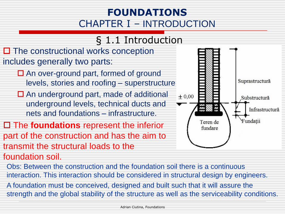
§ 1.1 Introduction The constructional works conception
includes generally two parts:
An over-ground part, formed of ground
levels, stories and roofing – superstructure
An underground part, made of additional
underground levels, technical ducts and
nets and foundations – infrastructure.
The foundations represent the inferior
part of the construction and has the aim to
transmit the structural loads to the
foundation soil.Obs: Between the construction and the foundation soil there is a continuous
interaction. This interaction should be considered in structural design by engineers.
A foundation must be conceived, designed and built such that it will assure the
strength and the global stability of the structure as well as the serviceability conditions.
§ 1.1 Introduction
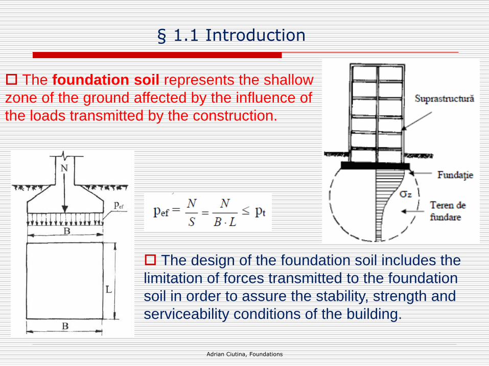
The foundation soil represents the shallow
zone of the ground affected by the influence of
the loads transmitted by the construction.
The design of the foundation soil includes the
limitation of forces transmitted to the foundation
soil in order to assure the stability, strength and
serviceability conditions of the building.
Adrian Ciutina, Foundations

§ 1.2 Classification of foundations
In function of the foundation depth, the foundations can be:
Adrian Ciutina, Foundations
Shallow
foundations
Deep
foundations

§ 1.2 Classification of foundations
In function of overtaking of the structural forces, the foundations
can be:
Rigid foundations, working in
compression only. Can be made of
plain concrete or masonry.
Elastic foundations working in bending
and compression. Must be made of
reinforced concrete.
Adrian Ciutina, Foundations

§ 1.2 Classification of foundations
In function of the transmission of loads, the foundations can be:
Direct foundations in which the transmission of loads is assured by
direct contact between the foundation base and the ground: single,
continuous, grid, mat, box foundations.
Indirect foundations in which the transmission of loads is assured
throughout the tip of the foundation and lateral friction: pile, column strip
Adrian Ciutina, Foundations
Other classifications of foundations:
In function of loading: compression, tearing, bending.
In function of the foundation material: compacted earth, plain or
reinforced concrete, steel foundations;
In function of the design procedure: gravity, fixed
In function of typology: single, split, special
In function of execution: in-situ, precast

The design of the foundations and foundation soils is done in
accordance with the EN 1997 - Geotechnical design.
The design situations are given in EN 1990 – Basis of design.
Specific actions are offered by EN 1991 – Actions on structures.
Adrian Ciutina, Foundations
The structure and the foundation soil are in continuous interaction.
According to EN 1997 - Any interaction between the structure and the
ground shall be taken into account when determining the actions to be
adopted in the design
CHAPTER II – BASIS OF DESIGN§ 2.1 Introduction in basis of design

§ 2.1 Introduction in basis of design
Adrian Ciutina, Foundations
movements due to creeping or
sliding or settling ground masses;
movements due to degradation,
dispersion, decomposition, self-
compaction;
movements and accelerations
caused by earthquakes, explosions,
vibrations and dynamic loads;
temperature effects, including frost
action;
ice loading;
imposed pre-stress in ground
anchors or struts;
downdrag.
the weight of soil, rock and water;
stresses in the ground;
earth pressures and ground-water pressure;
free water pressures, including wave
pressures;
ground-water pressures;
seepage forces;
dead and imposed loads from structures;
surcharges;
mooring forces;
removal of load or excavation of ground;
traffic loads;
movements caused by mining;
swelling and shrinkage caused by
vegetation, climate or moisture changes;
In geotechnical design, the following actions should be considered:

§ 2.2 Limit State Design
Limit State Design. Limit states: states beyond which the structure
no longer fulfils the relevant design criteria. They represent
idealizations of undesirable events or phenomena. In accordance with
EN 1990, the following limit states should be considered:
Ultimate limit states (ULS)
Serviceability limit states (SLS)
Adrian Ciutina, Foundations
Ultimate limit states: states
associated with collapse or with other
similar forms of structural failure
Serviceability limit states: states
that correspond to conditions beyond
which specified service requirements
(deflections, vibrations, cracks) for a
structure or structural member are no
longer met
§ 2.2 Limit State Design
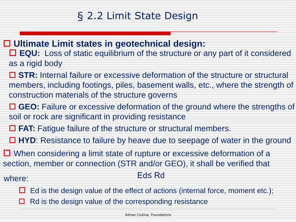
Ultimate Limit states in geotechnical design:
Adrian Ciutina, Foundations
EQU: Loss of static equilibrium of the structure or any part of it considered
as a rigid body
STR: Internal failure or excessive deformation of the structure or structural
members, including footings, piles, basement walls, etc., where the strength of
construction materials of the structure governs
GEO: Failure or excessive deformation of the ground where the strengths of
soil or rock are significant in providing resistance
FAT: Fatigue failure of the structure or structural members.
HYD: Resistance to failure by heave due to seepage of water in the ground
When considering a limit state of rupture or excessive deformation of a
section, member or connection (STR and/or GEO), it shall be verified that
Ed≤ Rdwhere:
Ed is the design value of the effect of actions (internal force, moment etc.);
Rd is the design value of the corresponding resistance

§ 2.2 Limit State Design
Serviceability Limit states in geotechnical design:
Adrian Ciutina, Foundations
At the SLS it shall be verified that:
Ed ≤ Cd
where:
Cd is the limiting design value of the relevant serviceability criterion.
Ed is the design value of the effects of actions specified in the serviceability
criterion, determined on the basis of the relevant combination
In general the serviceability conditions in geotechnical design are resumed to
checking the settlement conditions – related to the deformability of the soils
under foundation actions.

§ 2.3 Partial Safety Factors
Adrian Ciutina, Foundations
Partial Safety Method Factors.
Assessment of the reliability of structures in Eurocodes is based on
the concept of limit state design and verification by the partial factor
method.
Using this method, a structure is considered to be reliable if no
relevant limit state is exceeded for all selected design situations, when
using the design values of basic variables:
actions
material properties
geometrical data

Adrian Ciutina, Foundations
Partial Safety Method Factors - Actions.
The design value Fd of an action F can be expressed in general
terms as:
Fd = γf· Frep
With Frep = Ψ · Fk
where:
Fk is the characteristic value of the action.
Frep is the relevant representative value of the action.
γf is a partial factor for the action which takes account of the
possibility of unfavourable deviations of the action values from the
representative values
Ψ is either 1,00 or Ψ0, Ψ1 or Ψ2.
the combination value Ψ0Qk
the frequent value Ψ1Qk the quasi-permanent value Ψ2Qk
§ 2.3 Partial Safety Factors

Adrian Ciutina, Foundations
Partial Safety Method Factors – Design values of actions.
For a specific load case the design values of the effects of actions
(Ed) can be expressed in general terms as:
Ed = γSd · E {γf,i · Frep,i ; ad} i≥1
where:
ad is the design values of the geometrical data;
γSd is a partial factor taking account of uncertainties:
- in modelling the effects of actions;
- in some cases, in modelling the actions.
E {γf,i · Frep,i ; ad} is the effect of action for the design value of the
force Fd and the design geometrical characteristics ad
§ 2.3 Partial Safety Factors
Adrian Ciutina, Foundations
Partial Safety Method Factors – Materials.
The design value Xd of a material or product property can be
expressed in general terms as: Xd = η(Xk/γm)
where:
Xk is the characteristic value of the material property;
η is the mean value of the conversion factor taking into account:
– volume and scale effects,
– effects of moisture and temperature, and
– any other relevant parameters;
γm is the partial factor for the material or product property to take
account of:
– the possibility of an unfavourable deviation of a material or
product property from its characteristic value;
– the random part of the conversion factor η.
§ 2.3 Partial Safety Factors
Adrian Ciutina, Foundations
Partial Safety Method Factors – Geometrical Data.
Design values of geometrical data such as dimensions of members
that are used to assess action effects and/or resistances may be
represented by nominal values:
ad = anom
Where the effects of deviations in geometrical data (e.g. inaccuracy
in the load application or location of supports) are significant for the
reliability of the structure (e.g. by second order effects) the design
values of geometrical data shall be defined by:
ad = anom ± Δa
Where Δa takes account of:
the possibility of unfavourable deviations from the characteristic or
nominal values;
the cumulative effect of a simultaneous occurrence of several
geometrical deviations.
§ 2.3 Partial Safety Factors

Adrian Ciutina, Foundations
Partial Safety Method Factors – Design Resistances (R).
Partial factors may be applied either to ground properties (X) or
resistances (R) or to both:
Rd = R{γF Frep; Xk/γM; ad} or
Rd = R{γF Frep; Xk; ad} /γR or
Rd = R{γF Frep; Xk/γM; ad} /γR
In design procedures where the effects of actions are factored, the
partial factor for actions γF = 1,0.
§ 2.3 Partial Safety Factors

§ BIBLIOGRAPHY
Adrian Ciutina, Foundations
Partial Safety Method Factors – Geometrical Data.
1. Adler, L., Negru, I. - Industrializarea construcţiilor. Sinteză documentară INID, Bucureşti ,1981.
2. Agent, R., Postelnicu, T. - Calculul structurilor cu diafragme din beton armat. Ed. Tehnică, Bucureşti, 1982
3. Alagangi, M. - Contribuţii privind gradul de prefabricare la lucrările ciclului zero pentru clădiri de locuinţe P + 4etaje. Teză de
doctorat. Iaşi, 1982.
4. Andrei, S., Antonescu, I. - Geotehniă şi fundaţii. Institutul de Construcţii, Bucureşti, 1980.
5. Arimas, R., A. - Consolidation des sols par vibration. Paris, Rev. Construction nr. 7-8, 1968.
6. Atef Drak Al-Sebai - Contribuţii la studiul unor soluţii moderne de fundare directă a clădirilor. Teză de doctorat. Timişoara, 1983
7. Avram, C., Gruner, I. ş.a. - Clădiri multietajate din elemente spaţiale prefabricate. Conferinţa a VII-a de betoane, vol. II, Iaşi,
1975.
8. Beleş A., Mihăilescu C., Mihăilescu Ş. - Calculul construcţiilor amplasate pe terenuri deformabile (Interacţiunea structură-
fundaţieteren), Ed. Academiei RSR, Bucureşti, 1977
9. Bowles, J. - Fundazioni. Ed. McGraw-HillLibri Italia SRL, Milano, 1991.
10. Boţu, N., Muşat, V. - Geotechnique. Casa de Editură VENUS, Iaşi, 1998.
11. Brad, I., I. - Contribuţii la studiul interacţiunii suprastructură-fundaţie teren
la clădirile de locuinţe. Teză de doctorat. Timişoara, 1998.
12. Ciornei, A., Răileanu, P. - Cum dominăm pământurile macroporice sensibile la umezire, Editura Junimea, Iaşi, 2002.
13. Ciornei, A., - Cum concepem construcţiile civile, Editura Junimea, Iaşi, 2000.
14. Dascălu, V., Mihalache, A., Molocea, M., Păuleţ, C., Rotaru, I. - Aspecte teoretice şi practice ale realizării elevaţiilor
prefabricate spaţiale la clădirile de locuit din panouri mari. Rev. Construcţii nr.11, 1982.
15. EN 1997 - Geotechnical design.
16. EN 1990 – Basis of design.
17. EN 1991 – Actions on structures