Foundation & Soil Investigation
269
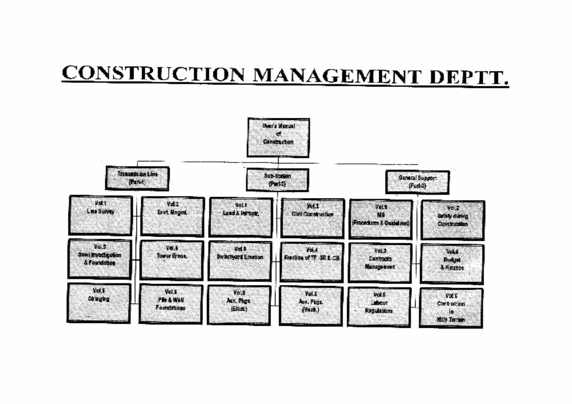
FOR INTERNAL CIRCULATION ONLY user’s manual of Construction Soil Investigation & Foundations Construction Management Power Grid Corporation of India Limited (A Government of India Enterprise) DOCUMENT CODE NO. : CM/TL/SOIL INVESTIGATION & FOUNDATIONS/FINAL/98 OCT, 1998
-
Upload
prithvirajd20 -
Category
Documents
-
view
127 -
download
8
Transcript of Foundation & Soil Investigation

FOR INTERNAL CIRCULATION ONLY
user’s manual of Construction
Soil Investigation&
Foundations
Construction ManagementPower Grid Corporation of India Limited
(A Government of India Enterprise)
DOCUMENT CODE NO. : CM/TL/SOIL INVESTIGATION & FOUNDATIONS/FINAL/98 OCT, 1998

CHAIRMAIN &
MANAGING DIRECTOR’S MESSAGE
It gives me immense pleasure to learn that Construction Management has come out with
further four volumes of User’s Manual of Construction : ‘Soil Investigation & Foundations’,
‘Pile & Well Foundations’, ‘Contracts Management’ and ‘Transformers & Reactors’.
The various changes in the wake of rapid advances in technologies and growing competition
on global basis has made it imperative to conceptualise the methods for optimizing our
resources; the 5M’s namely men, money, machines, materials and methods. They are the
basics to realize a construction project and time, cost & quality are its critical parameters.
The construction of transmission line is a wide canvas and complex in nature that needs a
multi disciplinary approach. However, no standard guidelines or manuals in consolidated
form are available for its various construction activities.
I compliment the Construction Management team for bringing out these manuals wherein
the main focus of the authors has been to combine the theoretical & practical aspects drawn
from their respective experience in transmission lines construction, academic institutions
and industry. An attempt has been made to explain the fundamentals in a simple & lucid
language. I am convinced that these manuals will act as guidelines and serve the needs of
our practicing Managers & site Engineers.
I should be our endeavour to follow these systems and procedures to enhance the quality of
construction management in transmission and quality power. More such User’s Manuals
covering the other related fields should be prepared for the benefit of the ultimate users at
our remote sites as well as for the younger generation inducted in POWERGRID.
(R.P. SINGH)
CONTENTS
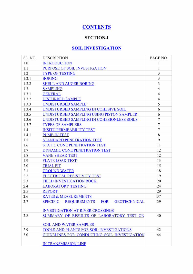
SECTION-I
SOIL INVESTIGATION
SL. NO. DESCRIPTION PAGE NO.1.0 INTRODUCTION 11.1 PURPOSE OF SOIL INVESTIGATION 11.2 TYPE OF TESTING 31.2.1 BORING 31.2.2 SHELL AND AUGER BORING 31.3 SAMPLING 41.3.1 GENERAL 41.3.2 DISTURBED SAMPLE 41.3.3 UNDISTURBED SAMPLE 51.3.4 UNDISTURBED SAMPLING IN COHESIVE SOIL 61.3.5 UNDISTURBED SAMPLING USING PISTON SAMPLER 61.3.6 UNDISTURBED SAMPLING IN COHESIONLESS SOILS 71.3.7 TYPES OF SAMPLERS 71.4 INSITU PERMEABILITY TEST 71.4.1 PUMP-IN TEST 81.5 STANDARD PENETRATION TEST 91.6 STATIC CONE PENETRATION TEST 111.7 DYNAMIC CONE PENETRATION TEST 121.8 VANE SHEAR TEST 121.9 PLATE LOAD TEST 132.0 TRIAL PIT 152.1 GROUND WATER 182.2 ELECTRICAL RESISTIVITY TEST 192.3 FIELD INVESTIGATION ROCK 202.4 LABORATORY TESTING 242.5 REPORT 292.6 RATES & MEASUREMENTS 372.7 SPECIFIC REQUIREMENTS FOR GEOTECHNICAL
INVESTIGATION AT RIVER CROSSINGS
39
2.8 SUMMARY OF RESULTS OF LABORATORY TEST ON
SOIL AND WATER SAMPLES
40
2.9 TOOLS AND PLANTS FOR SOIL INVESTIGATIONS 423.0 GUIDELINES FOR CONDUCTING SOIL INVESTIGATION
IN TRANSMISSION LINE
44

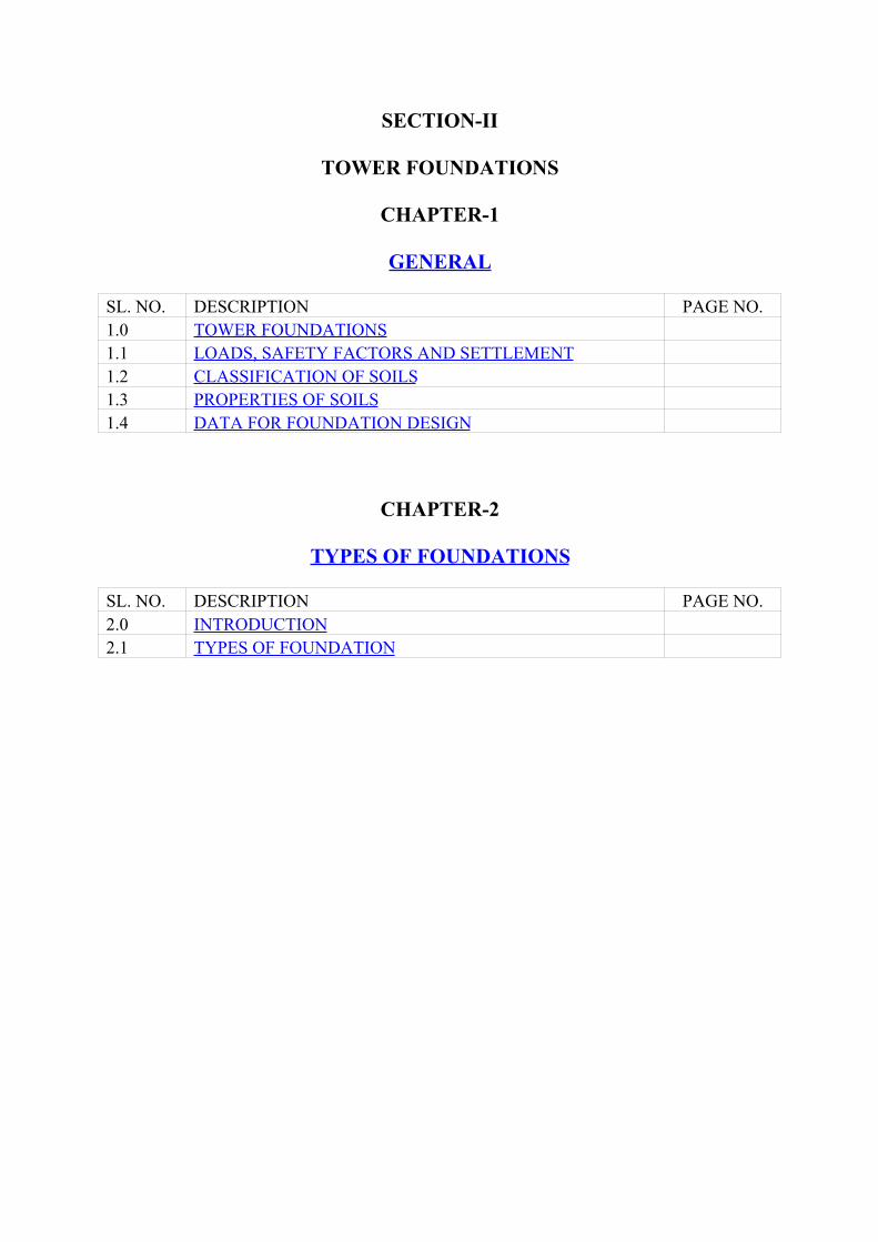
SECTION-II
TOWER FOUNDATIONS
CHAPTER-1
GENERAL
SL. NO. DESCRIPTION PAGE NO.1.0 TOWER FOUNDATIONS1.1 LOADS, SAFETY FACTORS AND SETTLEMENT1.2 CLASSIFICATION OF SOILS1.3 PROPERTIES OF SOILS1.4 DATA FOR FOUNDATION DESIGN
CHAPTER-2
TYPES OF FOUNDATIONS
SL. NO. DESCRIPTION PAGE NO.2.0 INTRODUCTION2.1 TYPES OF FOUNDATION
CHAPTER-3
CLASSIFICATION AND STUB SETTING
SL. NO. DESCRIPTION PAGE NO.3.0 LINE CONSTRUCTION3.1 INVESTIGATION AND SURVEY3.2 TRANSPORTATION3.3 FOUNDATION3.4 PREPARATION OF FOUNDATION SITE3.5 TYPE OF FOUNDATION TO BE ADOPTED3.6 PIT MARKING3.7 SHORING AND SHUTTERING3.8 DEWATERING3.9 EXCAVATION IN ROCK3.10 PROCEDURE FOR SETTING STUBS OF SITE BY
COMBINED STUB SETTING
CHAPTER-4
TYPES OF FOUNDATIONS
SL. NO. DESCRIPTION PAGE NO.4.0 CONCRETE TYPE4.1 MIXES4.2 SIZES OF AGGREGATES4.3 GRAVEL SUB-BASE4.4 REINFORCEMENT4.5 FORM WORK4.6 MIXING, PLACING AND COMPACTING OF CONCRETE4.7 BACK FILLING4.8 CURING
CHAPTER-5
PROTECTION OF FOUNDATION
SL. NO. DESCRIPTION PAGE NO.5.0 CONCRETE TYPE5.1 UPLIFT RESISTANCE

5.2 REVETMENT5.3 BENCHING5.4 PROTECTION OF FOUNDATION AGAINST CHEMICAL
WATER5.5 MEASUREMENT OF VOLUME FOR REVETMENT AND
BENCHING
CHAPTER-6
CONCRETE TECHNOLOGY
SL. NO. DESCRIPTION PAGE NO.6.1 INTRODUCTION6.2 PROPORTIONING CONCRETE MIXTURES6.3 FRESH CONCRETE6.4 HANDING AND BATCHING CONCRETE MATERIALS6.5 BATCH PLANTS AND MIXERS6.6 READY MIXED CONCRETE6.7 MOVING AND PLACING CONCRETE6.8 CONSOLIDATING CONCRETE6.9 RECOMMENDED VIBRATION PRACTICES6.10 FINISHING AND CURING CONCRETE6.11 PLACING CONCRETE IN COLD WEATHER6.12 PLACING CONCRETE IN HOT WEATHER
CHAPTER-7
MECHANISED CONSTRUCTION
SL. NO. DESCRIPTION PAGE NO.7.0 INTRODUCTION7.1 MECHANICAL CONSTRUCTION EQUIPMENT & THEIR
APPLICATIONS7.2 WORK STUDY ON CONSTRUCTION EQUIPMENT7.3 PLANT PURCHASE VERSUS PLANT HIRE7.4 SAFETY PROGRAMME7.5 WHY MECHANICAL CONSTRUCTION EQUIPMENT?7.6 PRODUCTION OUT PUTS7.7 PRODUCTION TRIAL7.8 ECONOMIC LIFE
CHAPTER-8
STANDARD FIELD QUALITY PLAN
SL. NO. DESCRIPTION PAGE NO.
8.0 STANDARD FIELD QUALITY PLAN FOR TRANSMISSION
LINE PACKAGES
CHAPTER-9
GUIDELINES
SL. NO. DESCRIPTION PAGE NO.9.0 PIT MARKING9.1 STUB SETTING9.2 CONSTRUCTION MATERIALS9.3 INSTALLATION OF REINFORCEMENT STEEL & FORM
BOXES9.4 MIXING, PLACING AND COMPACTING OF CONCRETE
CHAPTER-10
CHECK FORMAT
SL. NO. DESCRIPTION PAGE NO.1.0 CHECK FORMAT FOR PIT MARKING2.0 CHECK FORMAT FOR FOUNDATION CLASSIFICATION3.0 CHECK FORMAT FOR STUB SETTING4.0 CHECK FORMAT FOR CONSTRUCTION MATERIALS5.0 CHECK FORMAT FOR INSTALLATION OF
REINFORCEMENT STEEL & FORM BOXES6.0 CHECK FORMAT FOR MIXING, PLACING AND
COMPACTING OF CONCRETEANNEXURE-IA : TOOLS & PLANTS FOR EXCAVATION,
STUB SETTING AND CONCRETINGANNEXURE-IB : MANPOWER FOR EXCAVATION, STUB
SETTING & CONCRETING GANGANNEXURE-IC : REINFORCED CONCRETE RETAINING
WALLS
SECTION-1
Soil Investigation
___________________________________________________________________________
SECTIONONE
___________________________________________________________________________
SOIL INVESTIGATION
Back to contents page
1.0 INTRODUCTION
Back to contents page
An investigation of sill is essential for judging its suitability for the proposed
engineering works and for preparing adequate and economic design. In
general, the purpose of soil investigation is to obtain necessary information
about the soil and to know the engineering properties of soil which will be
affected.
Earlier, the soil investigation of locations of transmission line towers was not
very popular and general practice had been to adopt 4to 5 types of standard
design foundations for different classes of soils encountered. Only special
foundations in river beds necessitating huge volumes of concrete were
investigated for properties of soils. Now the soil investigation of normal
foundations is also felt necessary in good number of locations in the 400 kv
transmission lines which helps in better choice of standard foundation &
development of new designs to achieve overall cost, economy and minimise
chances of failure.
1.1 Purpose of soil investigation:
Back to contents page
a) Technical Consideration
b) Economic Consideration
a) Technical Considerations : An inadequate design or a conservative
choice of standard foundation can lead to a failure causing long outage
of transmission line. In modern practice, a large variety of standardised
foundations are being pre-designed with different sets of properties
attached to forseeably encountered soils. Aarge varity of soils are
encountered as length of transmission lines are increasing with voltage
llevels going up. To obtain optimal choice of pre-designed standard
foundations,it is very much necessary to have a proper scientific
knowledgfe of properties of soil against the back-drop of increasing
sizes of towers, foundations, loads, thereby minimising the risk of fail-
ures of foundations.
b) Economic Considerations : Among site erection activities, the
foundations form the major chunk of the cost. The cost of foundations
constitures 50 to 70% of the toral cost of erection depending upon
terrain conditions. It forms 10 to 15% of the total cost of transmission
line. A considerable saving in the foundation cost can be achieved by
having detailed knowledge of soil properties and making wide usage of
them in designing the foundations in sufficient types and classification
of the foundations in field to match the most optimum size and type of
foundation.
1.2 Types of Testing :
Back to contents page
1.2.1 Boring : Bore holes are generally taken at specified locations to obtain
information about the sub soil profile, its nature and strength and to collect soil
samples for strata identification and conducting laboratory tests. The minimum
diameter of the bore hole shall be 150 mm and boring shall be carried out in
accordance with the provision of IS:1892. Casing pipe is used in the bore hole
to support its side when a side fall is suspected to occur inside the borehole.
When casing pipe is used, it shall be ensured that its bottom end is at all times
less than 15cms above the bottom of the borehole and not below the level at
which the test has to be conducted or sampling has to be done. In case of
cohesion less soils the advancement of the casing pipe shall be such that it
does not disturb the soil to be tested or sampled. The casing shall be advanced
by slowly turning the casing pipe and not by driving.
1.2.2 Shell and Auger Boring: Cylindrical augers and shells with cutting edge on
teeth at the lower end can be used for making deep boring. Hand operated
rings are used for depths up to about 25m and the mechanized rings up to 50m.
Shell and auger boring can be used in all types of soil free from boulders. For
cohesion less soil below ground water table, the water table in the borehole
shall always be maintained at or above the ground water level. The use of
chisel bit is permitted in hard strate with SPT-N value greater than 100.Chisel
bits are also used to extend the borehole through local obstructions such as old
construction boulders, rocky formation etc. The various activities to be
conducted during the boring include standard penetration test, collection of
undisturbed and disturbed samples of soil at various depths, logging of
different layers of soil, depth of subsoil water and preparation of data sheets.
Further a series of tests have to be conducted on the disturbed and undisturbed
samples of soil at laboratory.
Back to contents page
1.3 Sampling :
Back to contents page
1.3.1 General :
Back to contents page
(a) Sufficient number of soil samples shall be collected. Disturbed soil
samples shall be collected for field identification and conducting tests
such as sieve analysis, index properties, specific gravity, chemical
analysis etc. Undisturbed sample shall be collected to estimate the
physical strength and settlement properties of the soil. All the
accessories required for sampling and the method of sampling shall
confirm to IS:2132.
(b) All the samples shall be identified with date, bore hole and trial pit
number, depth f sampling etc. It is also essential to mark and arrow
pointing towards the top surface of the sample as the soil was in-situ.
Care shall be taken to keep the core samples and box samples vertically
with the arrow directing upwards . The tube samples shall be properly
trimmed at one end and suitably caped and sealed with molten paraffin
wax.
1.3.2 Disturbed Sample
Back to contents page
a) Disturbed soil samples shall be collected in bore holes at regular
itervals.Jar samples weighing approximately 10N shall be collected in
boreholes at 0.5m intervals starting from a depth of 0.5 m below ground
level and at every identifiable change of strata to supplement the boring
records. Samples shall be immediately stored in air tight jars and shall fill
the jar as far as possible.
b) In elevated areas, if superficial material is available in plenty, then bulk
samples from a depth of about 0.5m below ground level shall be
collected to establish all the required properties to use it as a fill
material. Disturbed samples weighing about 250 N shall be collected at
shallow depths and immediately stored in polythene bags as per
IS:1892. The bags shall be sealed properly to avoid any change in
moisture content and they shall be kept in wooden boxes.
1.3.3 Undisturbed Sample :
Back to contents page
In each borehole undisturbed sample shall be collected at every change of
strata and depths of 1.0 4.0 7.0,10.013.0,15.5m and water at regular intervals
of 3.0m and as directed by the Engineer. The depth interval between the top
levels of undisturbed sampling and standard penetration test shall not be less
than 10.m. Undisturbed samples shall be of 100m dia and 450 mm length.
Samples shall be collected in such a manner that the structure of the soil and
its moisture content do not get asserted. The specifications for the accessories
required for sampling and the sampling procedure shall conform to IS:1892
and IS:2132. Undisturbed sampling in sand shall be done using compressed air
technique mentioned in IS:8763. Thin walled sampler shall be used to collect
undisturbed samples by pushing the tube into the soil. The sampling tube shall
have a smooth finish on both surfaces and minimum effective length of
450mm. The area ratio of sampling tubes shall be less than 12.5%. However,
in case of very stiff soils, area ratio up to 20% shall be permitted. Area ratio
should be as low as possible. In no case it should be greater than 25%. The
inside clearance of the sampler should lie between 1 to 3 percent and the
outside clearance should not be much greater than the inside clearance.
1.3.4 Undisturbed Sampling in Cohesive Soil
Back to contents page
Undisturbed samples in soft to stiff cohesive soils shall be obtained using a
thin walled sampler. In order to reduce the wall friction, suitable precautions
such as oiling the surfaces shall be taken.
1.3.5 Undisturbed Sampling using Piston Sampler
Back to contents page
Undisturbed samples in very loose saturated sandy and silty soils and very soft
clays shall be obtained by using a piston system. In soft clays and silty clays,
with water standing in the casing pipe, piston sampler shall be used to collect
undisturbed samples. During this method of sampling expert supervision is
called for. Accurate measurement of the depth of sampling, height of sampler,
stroke and length of sample recovery shall be recorded. After the sampler is
pushed to the required depth, both the sampler cylinder and piston system shall
be drawn up together ensuring that there shall not be any disturbance to the
sample which shall then be protected from changes in moisture content.
1.3.6 Undisturbed Sampling in Cohesion less Soils
Back to contents page
Undisturbed samples in cohesionless soils shall be obtained as per the
procedure given in IS:8763. Compressed air sampler shall be used to take
samples of cohesionless soils below water table.
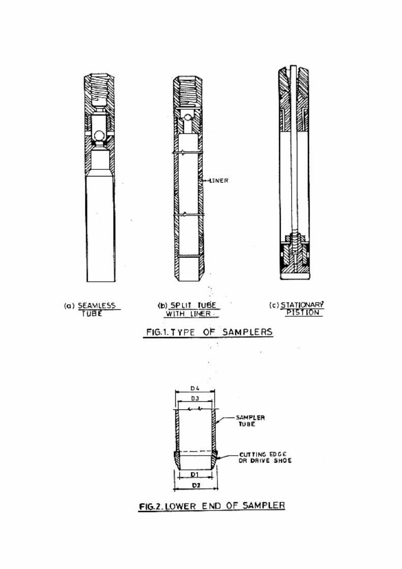

1.3.7 Type of Samplers:
Back to contents page
Samplers which shall be used commonly at sites are open drive sampler,
stationary piston sampler, and Rotary samplers depending upon the mode of
operation. Open drive types can be both the thick and thin wall samplers and
the stationary piston and the rotary types are thin wall sampler - depending
upon the area ratio (Fig.1 & Fig.2)
D22 - D12
Area ratio = ------------------- X 100 Percent D12
D3 - D1Inside Clearance = ---------------- X 100 percent
D1
D2 - D4
Outside Clearance = ---------------- X 100 percent
D4
1.4 In situ permeability test : In situ permeability test shall be conducted to
determine the water percolation capacity of overburden soil. The specification
for the equipments required for the test and the procedure of testing shall be in
accordance with IS: 5529, part -1. When it is required to carry out the
permeability test for a particular section of the soil strata above the ground
water table, bentonite slurry shall not be used while boring.
Back to contents page
1.4.1 Pump-in test:
Back to contents page
Pump-in test shall be conducted in the bore hole/trial pit by allowing water to
percolate into the soil. Choice of the method of testing shall depend on the soil
permeability and prevailing ground water level.
a) Constant Head Method ( in bore hole):
This test shall be conducted in boreholes where soils have a high
permeability i.e. it shall be allowed into the borehole through a
metering system ensuring gravity flow at constant head so as to
maintain a steady water level in the borehole. A reference mark shall
be made at a convenient level which can be easily seen in the casing
pipe to note down the fluctuations of water level. The fluctuation shall
be counteracted by varying the quantity of water flowing into the
borehole. The elevation of water shall be observed at every 5 minute
interval. When three consecutive readings show constant value, the
necessary observations such as flow rate, elevation of water surface
above test depth, diameter of casing pipe etc. Shall be made and
recorded as per the proforma recommended in IS:5529, PART-I,
Appendix-A.
b) Falling head method ( in bore hole)
This method shall ve adopted for relatively less permeable soils where
the discharge is small and where the soil can stand without casing. The
test section shall be seated by the bottom of the borehole and a packer
at the top of the test section. If the test has to be conducted at an
intermediate section of a prebored hole then, double packer shall be
used . Access to the test section through the packer shall be by means
of a pipe which shall extend to above the ground level. Water shall be
filled into the pipe upto the level marked just below the top of the pipe
and water allowed to drain into the test section. The water level in the
pipe shall be recorded at regular intervals as mentioned in
IS:5229,part-I, Appendix- B. The test shall be repeated till constant
records of water level are achieved.
1.5 Standard penetration Test :
Back to contents page
The test shall be performed in a clean hole, 55 to 150 mm in diameter. A
casing or drilling mud shall be used to support the sides of the hole. The test
shall be conducted at depth of 2.0, 3.0, 5.0, 6.0, 8.0, 9.0, 11.0, 12.0, 14.0, m
and at 3.0m intervals and every change of strata and as per the direction of the
Engineer-in-charge. A standard thick wall split-tube sampler, 50.8 mm shall be
driven into the undisturbed soil at the bottom of the hole under the blows of a
65 kg drive weight with 75 cm free fall. The minimum open length of the
sampler should be 60 cm. The sampler shall be first driven through 15 cm as a
seating drive. It shall be further driven through 30cm or until 100 blows are
applied. The number of blows required to give the sampler 30 cm beyond the
seating drive, is termed as penetration resistance N. This test shall be
discontinued when the blow count is equal to 100 or the penetration is less
than2.5 cm for 50 blows whichever is earlier. At the location were the test is
discontinued the penetration and the number of blows shall be reported.
Sufficient quantity of disturbed soil samples shall be collected from the split
spoon sampler for identification and laboratory testing.
Following Tables give some of the empirical correlation of the soil properties
with the penetration resistance corrected for depth and for fine saturated sand.
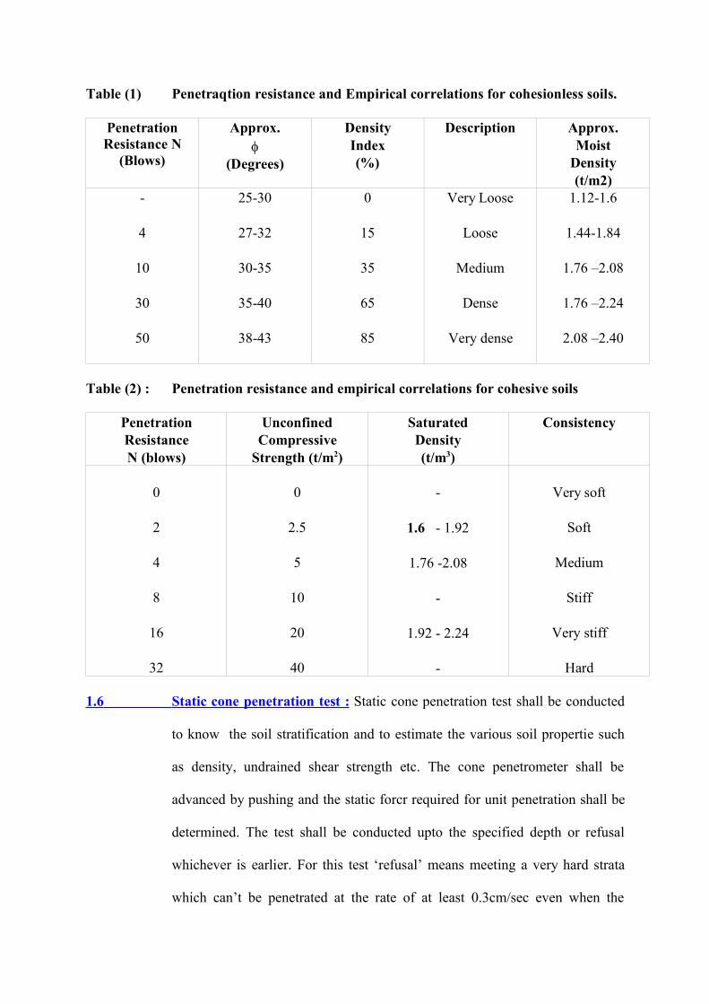
Table (1) Penetraqtion resistance and Empirical correlations for cohesionless soils.
PenetrationResistance N
(Blows)
Approx.
(Degrees)
DensityIndex(%)
Description Approx.Moist
Density(t/m2)
-
4
10
30
50
25-30
27-32
30-35
35-40
38-43
0
15
35
65
85
Very Loose
Loose
Medium
Dense
Very dense
1.12-1.6
1.44-1.84
1.76 –2.08
1.76 –2.24
2.08 –2.40
Table (2) : Penetration resistance and empirical correlations for cohesive soils
PenetrationResistanceN (blows)
UnconfinedCompressive
Strength (t/m2)
SaturatedDensity(t/m3)
Consistency
0
2
4
8
16
32
0
2.5
5
10
20
40
-
1.6 - 1.92
1.76 -2.08
-
1.92 - 2.24
-
Very soft
Soft
Medium
Stiff
Very stiff
Hard
1.6 Static cone penetration test : Static cone penetration test shall be conducted
to know the soil stratification and to estimate the various soil propertie such
as density, undrained shear strength etc. The cone penetrometer shall be
advanced by pushing and the static forcr required for unit penetration shall be
determined. The test shall be conducted upto the specified depth or refusal
whichever is earlier. For this test ‘refusal’ means meeting a very hard strata
which can’t be penetrated at the rate of at least 0.3cm/sec even when the
equipment is loaded to its full capacity. The specifications for the equipment
and accessories required for performing the test, test procedure, field
observations and reporting of results shall conform to 1S: 4968, Part 111. Only
100 kN capacity mechanically operated equipment shall be used. At the
ground level, preboring upto 0.5 m depth shall be permitted if the overlying
strata is hard. Continuous record of the penetration resistance shall be
maintained.
Back to contents page
1.7 Dynamic cone penetration test: Dynamic cone penetration test shall be conducted to
predict stratification, density, bearing capacity etc of soils. The test shall be conducted
upto the specified depth or refusal whichever is earlier. Refusal shall be considered when
the blow count exceeds 150 for 300mm penetration. The specification for the equipment
and accessories re- quired for performing this test, test procedure, field observations and
reporting of results shall conform to 18:4968 Part-ll. The driving system shall comprise
of a 650 weight having a free fall of 0.75m. The cone shall be of 65 mm diameter
provided with vents for'continuous flow of bentonite slurry through the cone and rods in
order to avoid friction between the rods & soil. On completion of the test, the result shall
be presented as a continuous record of the number of blows required for every 300mm
penetration of the cone into the soil in a suitable chart supplemented by a graphical plot
of blow count for 300 mm penetration vs. depth.
Back to contents page
1.8 Vane shear test: Field vane shear test shall be performed inside the borehole
to determine the undrained shear strength of cohesive soil -especially of soft
and sensitive clays, which are highly susceptible to sampling disturbance. The
vane shear test consist of four thin steel plates called vanes, welded
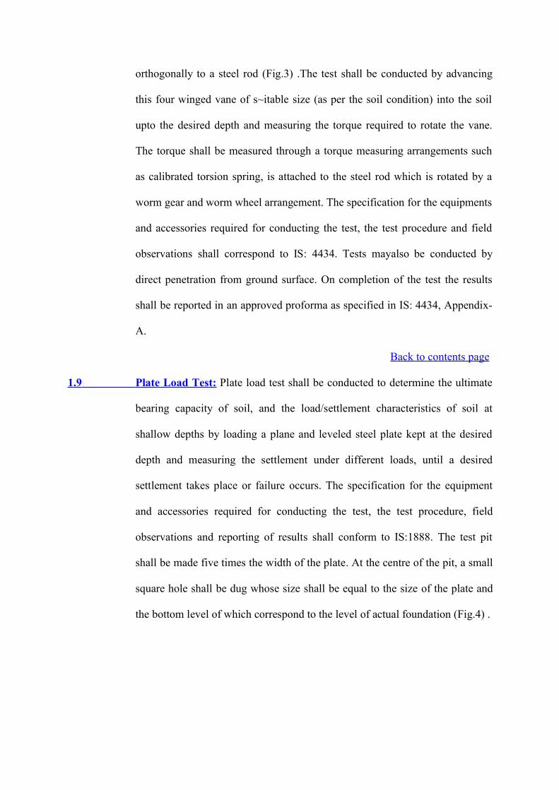
orthogonally to a steel rod (Fig.3) .The test shall be conducted by advancing
this four winged vane of s~itable size (as per the soil condition) into the soil
upto the desired depth and measuring the torque required to rotate the vane.
The torque shall be measured through a torque measuring arrangements such
as calibrated torsion spring, is attached to the steel rod which is rotated by a
worm gear and worm wheel arrangement. The specification for the equipments
and accessories required for conducting the test, the test procedure and field
observations shall correspond to IS: 4434. Tests mayalso be conducted by
direct penetration from ground surface. On completion of the test the results
shall be reported in an approved proforma as specified in IS: 4434, Appendix-
A.
Back to contents page
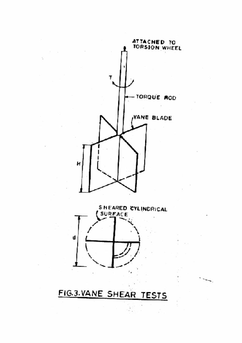
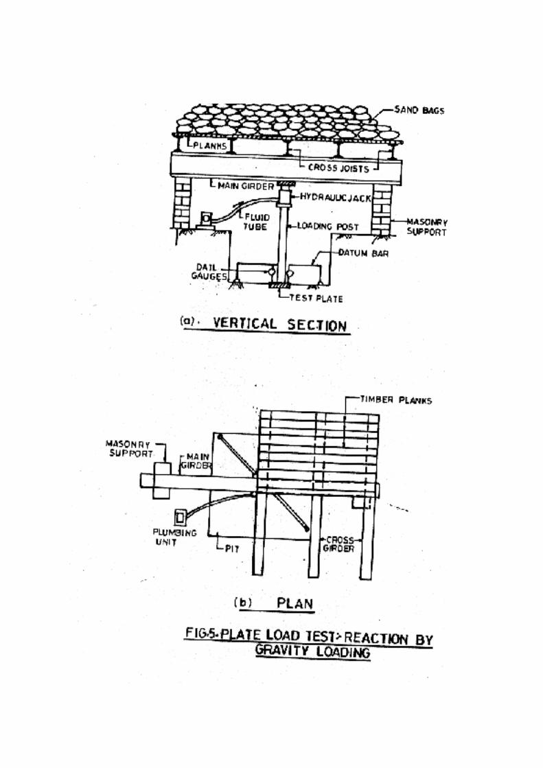
1.9 Plate Load Test: Plate load test shall be conducted to determine the ultimate
bearing capacity of soil, and the load/settlement characteristics of soil at
shallow depths by loading a plane and leveled steel plate kept at the desired
depth and measuring the settlement under different loads, until a desired
settlement takes place or failure occurs. The specification for the equipment
and accessories required for conducting the test, the test procedure, field
observations and reporting of results shall conform to IS:1888. The test pit
shall be made five times the width of the plate. At the centre of the pit, a small
square hole shall be dug whose size shall be equal to the size of the plate and
the bottom level of which correspond to the level of actual foundation (Fig.4) .

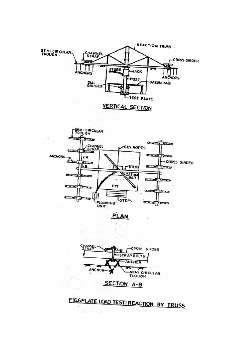
The loading to the test plate shall be applied with the help of a hydraulic jack.
The reaction of the hydraulic jack shall be borne by either of the following two
methods:
a) Gravity loading platform method
b) Reaction truss method.
In case of gravity loading method a platform shall be constructed over a
vertical column resting on the test plate and the loading shall be done with the
help of sand bags, stones or concrete blocks. The general arrangement of the
set up for this method is shown in Fig. 5 & 6.
If the water table is at a depth higher than the specified test depth, the
groundwater shall be lowered and maintained at the test depth for the entire
duration of the test.
1.9.1 A seating load of 70 gm/sq.cm shall be applied and after the dial gauge
readings are stabilized , the load shall be released and the initial readings of
the dial gauges recorded after they indicate constant reading. The load shall be
increased in stages. These stages shall be 20, 40, 70, 100, 150, 200, 250, 300,
400, 500, 600 and 800 KN per sq.m. or as directed by the Engineer. Under
each loading stage, record of Time vs Settlement shall be kept as specified in
IS: 1888.
The load shall be maintained for a minimum duration of one hour or till the
settlement rate reduces to 0.02 mm/ min whichever is later. No extrapolation
of settlement rate from periods less than one hour shall be permitted.
1.9.2 Loading shall be carried out in stages as specified above till one of the
following conditions occurs.
a) Failure of the soil under the plate i.e. the settlement of the plate at
constant load becomes progressive and reaches a value of 40 mm or
more.
b) Total settlement of the plate is more than 40 mm.
c) Load intensity of 800 KN/Sq.m is reached without failure of the soil.
1.9.3 Dial gauge readings for settlement shall generally be taken at
1,2.25,4,6.25,9,16,25,60,90 and 120 minutes from the commencement of each stage
of loading. Thereafter the readings shall be taken at hourly intervals upto a further 4
hours and at two hours intervals thereafter for another 6 hours .
2.0 Trial pit
Back to contents page
2.0.1 Trial pits shall be of minimum 2mx2m size at the bottom so as to permit easy access
for visual examination of walls of the pit and to facilitate sampling and insitu testing
operations. pits shall be upto 4 m deep or as per the directions of the Engineer.
Precautions shall be taken to ensure the stability of pit walls including provision of
shoring, if necessary, as per IS: 4453: Precautions shall be taken to prevent surface
water draining into the pit. Arrangements shall be made for dewatering if the pit is
extended below water table. Trial pits shall be kept dry and a ladder shall be provided
for easy access to the bottom of the pit. In-situ tests shall be conducted and
undisturbed samples shall be collected immediately on reaching the specified depth so
as to avoid substantial changes in moisture content of the subsoil. Arrangements shall
be made for barriers, protective measures and lighting necessary for the period the pits
remain open.
2.0.2 A note on the visual examination of soil strata shall be prepared. This should include
the nature, colour, consistency and visual classification of the soil, thickness of soil
strata, groundwater table, if any, etc.
2.0.3 Undisturbed samples shall be collected at 1.0, 2.0, 3.0 m depth and at the termination
depth in all the pits.
a) Chunk Samples
In cohesive soils, undisturbed samples of regular shapes shall be
collected. The samples shall be cut and trimmed to a suitable size
(0.3x0.3x0.3m). A square area (0.35x0.35m) shall be marked at the
centre of the leveled surface at the bottom of the pit. Without
disturbing the soil inside the marked area, the soil around this marking
shall be carefully removed upto a depth of 0.3Sm. The four vertical
faces of the soil block protruding at the centre to be trimmed slowly so
that its size reduces to 0.3mx0.3m. Wax paper cut to suitable size shall
be wrapped uniformly covered with two layers of thin cloth over all the
S exposed surfaces of the soil block and sealed properly using molten
wax. A firmly constructed wooden box of size 0.3Sx0.35x0.35m
(internal dimensions) with the top and bottom open shall be placed
around the soil block and held such that its top edge protrudes just
above the surface of the block. The space between the soil block and
the box shall be filled uniformly and tightly with moist sawdust. The
top surface shall also be covered with saw dust before nailing the
wooden lid to cover the box firmly taking care that the soil block is not
disturbed. The area of contact between the bottom portion of the block
and the ground shall be reduced slowly by removing soil in small
quantities using small rods, so that the block can be separated from the
ground slowly without disturbance. After inverting the wooden box
along with the soil block, the bottom portion shall be trimmed and
covered with wax paper, cloth and sealed with molten wax. A wooden
lid shall be nailed to the box after providing proper saw dust cushion
below it. An arrow mark shall be made on the vertical face of the
wooden box to indicate the top surface along wi th the coordinates and
depth of sampling .
b) Tube Samples
Undisturbed tube samples may also be obtained by means of a l00mm
diameter sampling tube with a cutting edge. The sampler shall be
slightly oiled or greased inside and outside to reduce friction. The
sampler shall be pushed into the soil and while doing so, soil around
the tube shall be carefully removed. In case it is not possible to push
the sample, it may be driven by light blows from a "monkey".
2.0.4 In each trial pit the soil in-situ density shall be determined by the sand
replacement method. The specifications, equipments, accessories required for
the test and test procedure shall be as per IS: 2720, Part- XXVIII. No separate
payment shall be made for this test.
2.1 Ground Water
Back to contents page
2.1.1 One of the following methods shall be adopted for determining the ground water table
in bore holes as per IS: 693 5 and as per the lnstructions of the Engineer.
a) In permeable soils, the water level in the hole shall be allowed to
stablise after depressing it adequately by bailing. When the water level
inside the bore hole is found to be stable, the depth of water level
below ground level shall be measured. Stability of sides and bottom of
the bore hole shall be ensured at all times.
b) For both permeable and impermeable soils, the [following method
shall be suitable. The bore hole shall be filled with water and then
bailed out to various depths. Observations on the rise or fall of water
level shall be made at each depth. The level at which neither a fall nor
a rise is observed shall be considered as the water table elevation. This
shall be established by three successive readings of water level taken at
an interval of two hours.
2.1.2 In case any variation in the groundwater level is observed in any specific boreholes,
then the water level in these I boreholes shall be recorded daily during the course of
the field investigation. Levels in nearby wells, streams, etc., if any, shall also be noted
whenever these readings are taken.
2.1.3 Sub-soil Water Samples
a) Sub-soil water samples shall be collected for carrying out chemical
analysis thereon. Representative samples of groundwater shall be
collected when it is first encountered in bore holes before the addition
of water to aid boring or drilling.
b) Chemical analysis of water samples shall include determination of pH
value; turbidity, sulphate, carbonate, nitrate and chloride contents;
presence of organic matter and suspended solids. Chemical
preservatives maybe added to the sample for cases as specified in'the
test method/IS codes. This shall only be done if analysis cannot be
conducted within an hour of collection and shall have the prior written
permission and approval of the Engineer.
2.2 Electrical Resistivity Test
Back to contents page
This test shall be conducted to determine the Electrical resistivity of soil
required for designing safety grounding system for the entire switch yard area.
The specifications for the equipments and other accessories required for
performing electrical resistivity test, the test procedure, and reporting of field
observations shall conform to 1S:3043. The test shall be conducted using
Wanner's four electrode method as specified in 1S:1892,Appendix-
B2.Unlessotherwisespecified, at each test location, the test shall be conducted
along two perpendicular lines parallel to the coordinate axes. On each line a
minimum of 8 to 10 readings shall be taken by changing the spacing of the
electrodes from an initial small value of 0.5m upto a distance of 10.0m.
2.3 Field Investigation Rock
Back to contents page
2.3.1 Rock Drilling
a) Boring shall be continued in large hard fragments or natural rock beds
like but not limited to igneous, sedimentary and metamorphic
formations. The equipments, method and the procedure for drilling
operation shall conform to IS:1892. The starting depth of drilling in
rock shall be certified by the Engineer. The portion drilled in rock shall
be backfilled with cement and sand (1:3) grout.
b) Drilling shall be carried out with NX size tungston carbide (TC) or
diamond tipped drill bits depending on the type of rock and as per
IS:6926. Suitable type of drill bit (TC/Diamond) and core catchers
shall be used to ensure continuous and good core recovery. Core
barrels and core catchers shall be used for breaking off the core and
retaining i t when the rods are withdrawn. Double tube core barrels
shall be used to ensure better core recovery and to pick up cores from
layers of bed rock. Water shall be circulated continuously down the
hollow rods and the sludge conveying the rock cuttings to the surface
shall be collected. A very high recovery ratio shall be aimed at in order
to get a satisfactory undisturbed sample. Core of minimum 1.5m length
shall be aimed at. Normally TC bit shall be used. Change over to a
diamond bit shall require the specific written approval of the Engineer
and his decision whether a TC or a diamond bit is to be used shall be
final and binding on the Contractor.
c) No drilling run shall exceed 1.5m in length. If the core recovery is less
than 80% in any run the length of the subsequent run shall be reduced
to 0.75m. During drilling operations observations on return water, rate
of penetration, etc., shall be made and recorded as per IS:5313.
i) The colour of return water at regular intervals, the depth at
which any change of colour of return water is observed, the
depth of occurrence and amount of flow of hot water, if
encountered, shall be recorded.
ii) The depth through which a uniform rate of penetration was
maintained, the depth at which marked change in rate of
penetration or sudden fall of drill rod occurs the depth at which
any blockage of drill bit causing core loss, if any, shall be
recorded.
iii) Any heavy vibration or torque noticed during drilling should be
recorded together with the depth of occurrence.
iv) Special conditions like the depth at which grouting was done
during drilling fluid, observation of gas discharge with return
water etc., shall also be observed and recorded.
v) All the observations and other details shall be recorded as a
daily drill and reported in a proforma as given in IS:5313.
d) Core samples shall be extracted by the application of a continuous
pressure at one end of the core with the barrel held horizontally without
vibration. Friable cores shall be extracted from the barrel directly into
a suitable sized half round plastic channel section. Care shall be taken
to maintain the direction of extrusion of sample same as while coring
to avoid stress reversal.
e) Immediately after withdrawl from the core barrel, the cores shall be
placed in a tray and transferred to boxes specially prepared for the
purpose. The boxes shall be made from seasoned timber or any other
durable material and shall be indexed on top of the lid as per IS : 4078.
The cores shall be numbered serially and arranged in the boxes in a
sequential order. The description of the core samples shall be recorded
as per IS : 4464. Where no core is recovered, it shall be recorded as
specified in the standard. Continuous record of core recovery and RQD
to be mentioned in the corelog as per IS : 11315 Part-II.
2.3.2 Permeability Test
Permeability Test shall be conducted in bedrock inside the drilled holes by
pumping in water under pressure to determine the percolation capacity of the
rock strata. This test shall be conducted in uncased and ungrouted sections of
the drill hole and the use of bentonite slurry during drilling is strictly
prohibited when this test has to be conducted.
Clear and clean water shall be used for the purpose of both drilling and testing.
The equipments required and the procedure to be followed for conducting the
test shall conform to IS : 5529, Part-II. The length of the test section shall be
either 1.5m or 3.0 m as per field conditions and the directions of the Engineer.
The level of water table, if any, in the drill hole shall be recorded and the drill
hole shall be cleaned before beginning the test. Depending upon the depth of
the test section, single packer or double packer method shall be adopted. Care
shall be taken to see that all joints and connections are watertight during the
test.
a) Single Packer Method
This method shall be adopted when the bottom elevation of the test
section is the same as the bottom of the drill hole and where it is
considered necessary to know the permeability values during drilling
itself. This test shall be useful where the full length of the hoe cannot
stand uncased or ungrouted. The packer shall be fixed at the top level
of test section such that only the test section lies below the packer.
Water shall then be pumped through a pipe into the test section under a
particular pressure and maintaining it till a constant quantity of water
intake is observed. The amount of water percolating through the hole
shall be recorded at every 5 mm intervals. The test shall be repeated by
increasing the pressure at regular intervals upto a pressure limit as
specified in IS : 5529, Part-II. The details and observations during the
test shall be suitably recorded in a proforma recommended in IS : 5529,
Part-II, Appendix-B.
b) Double Packer Method
This method shall be used when the permeability of an isolated section
inside a drill hole has to be determined. Packers shall be fixed both at
the top and bottom of the test section such that their spacing is exactly
equal to the length of the test section.
2.4 Laboratory Testing
Back to contents page
2.4.1 Essential Requirements
a) Depending on the type of sub strata encountered, appropriate laboratory
tests shall be conducted on soil and rock samples collected in the field.
Laboratory tests shall be scheduled and performed by qualified and
experienced personnel who are thoroughly conversant with the work. Tests
indicated in the schedule of items shall be performed on soil, water and
rock samples as per relevant IS: codes. One copy of all the laboratory test
data records shall be submitted to the Powergrid progressively every week.
Laboratory tests shall be carried out concurrently with field investigation
since initial laboratory test results could be useful in planning the later
stages of fieldwork. A schedule of laboratory tests shall be established by
the Contractor to the satisfaction of the Engineer within one week of
completion of the first borehole.
b) Laboratory tests shall be conducted using approved apparatus comply
in with the requirements and specifications of/'Indian Standards or
other approved standards for this class of work. It shall be checked that
the apparatus are in good working condition before starting the
laboratory tests./Calibration of all the instruments and their accessories
shall be done carefully and precisely. The tests shall be conducted at an
approved laboratory.
c) All samples, whether undisturbed or disturbed, shall be extracted,
prepared and examined by competent personnel properly trained and
experienced in soil sampling, examination, testing and in using the
apparatus as per the specified standards.
d) Undisturbed soil samples retained in lines or seamless tube /samplers
shall be taken out without causing any disturbance to the samples using
suitably designed extruders just prior to actual testing. If the extruder is
horizontal, proper support shall be provided to prevent the sample from
breaking. For screw type extruders, the pushing head shall be free from
the screw shaft so that no torque is app11ed to the soil sample in
contact with the pushing head. For soft clay samples, the sample tube
shall be cut by mean of a high speed hacksaw to proper test length and
placed over the mould before pushing the sample into it with a suitable
piston.
e) While extracting a sample from a liner or tube, care shall be taken to
see that its direction of movement is the same as that during sampling
to avoid stress reversal.
2.4.2 Tests
Tests as indicated in this specification and as called for by the Engineer shall
be conducted. These tests shall include but not be limited to the following.
a) Tests on Undisturbed and Disturbed Samples
- Visual and Engineering Classification
- Sieve Analysis and Hydrometer Analysis
- Liquid, Plastic and Shrinkage Limits
- Specific Gravity
- Chemical Analysis
- Swell Pressure and Free Swell index determination
- Proctor Compaction test
- California Bearing Ratio
b) Tests on Undisturbed Samples
- Bulk Density and Moisture Content
- Relative Density (for sand)
- Unconfined Compression Test
- Box Shear Test (in case of sand)
- Triaxial Shear Tests: (depending on the type of soil and field
conditions on undisturbed or remoulded samples )
i) Unconsolidated undrained,
ii) Consolidated Undrained Test with the Measurement of Pore
Water Pressure.
iii) Consolidated Drained.
- Consolidation
c) Tests on Rock Samples
- Visual Classification
- Moisture Content, Porosity and Density Specific Gravity Hardness
- Slake durability
- Unconfined Compression test (both saturated and at insitu water
content ) -Point load strength index
- Deformability test (both saturated and dry, samples)
d) Chemical Analysis of Sub soil water
2.4.3 Salient Test Requirements
a) Remoulded soil specimen, whenever desired, shall be fully reworked at
field density and moisture content . For conducting CBR test and
triaxial test for dyke and road material the sample shall be remoulded
to 95% of standard proctor density.
b) Triaxial shear test shall be conducted on undisturbed soil samples,
saturated by the application of back pressure. Only if the water table is
at sufficient depth so that chances of its rising to the base of the footing
are meagre or nil, the triaxial tests shall be performed on specimens at
natural moisture content. Each test shall be carried out on a set of three
test specimens from one sample at cell pressures equal to 100, 200 and
300 KN/sq.m. or as required depending on the soil conditions .
c) Effective stress triaxial shear test could be either consolidated drained
or consolidated undrained with pore water pressure measurement. The
test shall be conducted at cell pressure of 100,200 and 300 KN/ sqm.
increased in stages of 50 KN/sqm. ensuring complete consolidation at
each stage.
d) Direct shear test shall be conducted on undisturbed soil samples. The
three normal vertical stresses for each test shall be l00, 200 and 300
KN/sq.m. or as required as per the soil conditions .
e) Consolidation test shall have loading stages of 10, 25,50,75,100,200,
400and800KN/Sq.m. Rebound curve shall be recorded for all the
samples by unloading the specimen at the in-situ stress of the
specimen. Additional rebound curves shall also be recorded whenever
desired by the Engineer.
f) Chemical analysis of sub-soil shall include determination of pH value;
carbonate, sulphate (both SO3andSO4) , chloride and nitrate contents;
organic matter; salinity and any other chemical harmful. to the
foundation material. The contents in soils shall be indicated as
percentage ( % ) .
g) Chemical analysis of sub-soil water sample shall include the determination
of the properties such as colour, odour, turbidity, pH value and specific
conductivity both at 25 deg.C and chemical contents such as Carborates,
Surphates(both SO3 and SO4), Chlorides, Nitratesm Organic matter and any
other chemical harmful to the founmdation material. The contents such as
Sulphates, etc. shall be indicted as ppm by weight.
h) The lab CBR test shall be performed on undisturbed and remoulded
sample for soaked and unsoaked condition.
2.5 Report
Back to contents page
2.5.1 General
a) On completion of all the field and laboratory work, the Contractor shall
submit a formal report containing Geological information of the region,
procedure adopted for investigation, field observations, summarised
test data, conclusion and recommendations. The report shall include
detailed borelogs, subsoil sections, field test results, laboratory
observations and test results both in tabular as well as graphical form,
practical and theoritical considerations for the interpretation of test
results, the supporting calculations for the conclusions drawn, etc.
Initially, the Contractor shall submit three copies of the report in draft
from for the Owner's review.
b) The Contractor's qualified Geotechnical engineer shall visit the Owners
Corporate office for a detailed discussion on the Owners comments on
his draft report. During the discussions, it shall be decided as to the
modifications that need to be done in the draft report. Thereafter the
Contractor shall incorporate in his report the agreed modifications and
after get ting the amended draft report approved, ten copies of the
detailed final report shall be submitted alongwith one set of
reproducibles of the graphs, tables, etc .
c) The detailed final report based on field observations, in-situ and
laboratory tests shall encompass theoretical as well as practical
considerations for foundations for different types of structures
envisaged in the area under investigation. The Contractor shall
acquaint himself about the type of structures, foundation loads and
other information required from the Engineer.
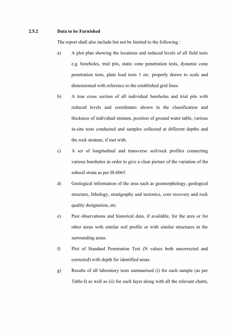
2.5.2 Data to be Furnished
The report shall also include but not be limited to the following :
a) A plot plan showing the locations and reduced levels of all field tests
e.g. boreholes, trial pits, static cone penetration tests, dynamic cone
penetration tests, plate load tests 1 etc. properly drawn to scale and
dimensioned with reference to the established grid lines.
b) A true cross section of all individual boreholes and trial pits with
reduced levels and coordinates shown in the classification and
thickness of individual stratum, position of ground water table, various
in-situ tests conducted and samples collected at different depths and
the rock stratum, if met with.
c) A set of longitudinal and transverse soil/rock profiles connecting
various boreholes in order to give a clear picture of the variation of the
subsoil strata as per IS:6065.
d) Geological information of the area such as geomorphology, geological
structure, lithology, stratigraphy and tectonics, core recovery and rock
quality designation, etc.
e) Past observations and historical data, if available, for the area or for
other areas with similar soil profile or with similar structures in the
surrounding areas.
f) Plot of Standard Penetration Test (N values both uncorrected and
corrected) with depth for identified areas.
g) Results of all laboratory tests summarised (i) for each sample (as per
Table-I) as well as (ii) for each layer along with all the relevant charts,
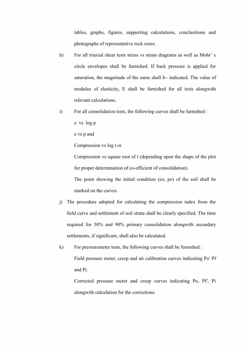
tables, graphs, figures, supporting calculations, conclusitions and
photographs of representative rock cores.
h) For all triaxial shear tests stress vs strain diagrams as well as Mohr’ s
circle envelopes shall be furnished. If back pressure is applied for
saturation, the magnitude of the same shall b~ indicated. The value of
modulus of elasticity, E shall be furnished for all tests alongwith
relevant calculations.
i) For all consolidation tests, the following curves shall be furnished :
e vs log p
e vs p and
Compression vs log t or
Compression vs square root of t (depending upon the shape of the plot
for proper determination of co-efficient of consolidation).
The point showing the initial condition (eo, po) of the soil shall be
marked on the curves.
j) The procedure adopted for calculating the compression index from the
field curve and settlement of soil strata shall be clearly specified. The time
required for 50% and 90% primary consolidation alongwith secondary
settlements, if significant, shall also be calculated.
k) For pressuremeter tests, the following curves shall be furnished :
Field pressure meter, creep and air calibration curves indicating Po' Pf
and Pi.
Corrected pressure meter and creep curves indicating Po, Pf', Pi
alongwith calculation for the corrections.
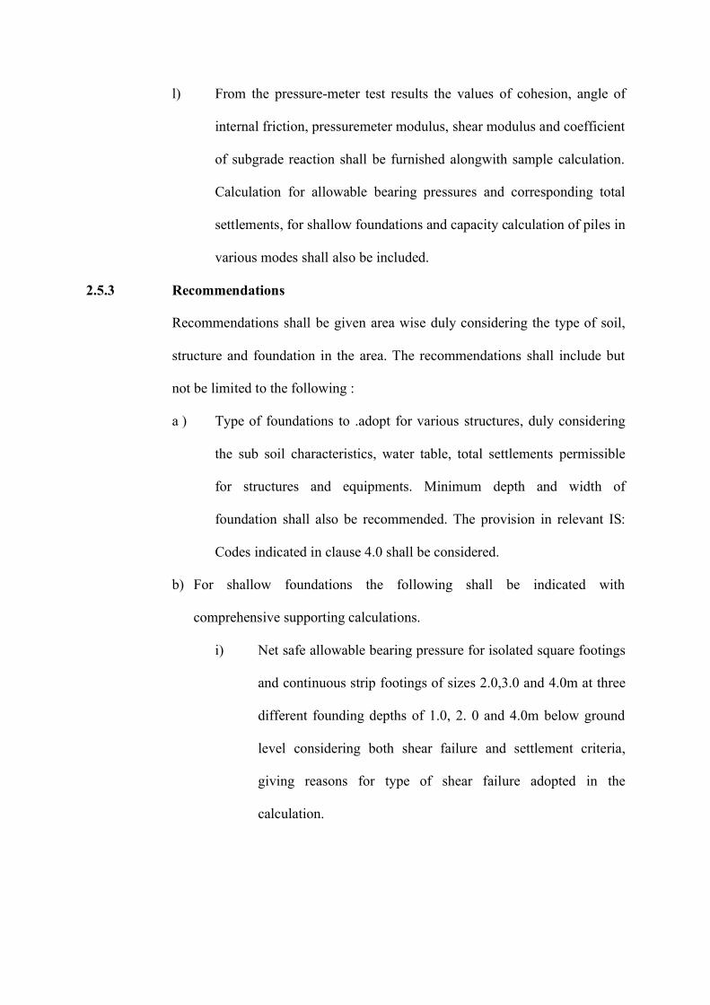
l) From the pressure-meter test results the values of cohesion, angle of
internal friction, pressuremeter modulus, shear modulus and coefficient
of subgrade reaction shall be furnished alongwith sample calculation.
Calculation for allowable bearing pressures and corresponding total
settlements, for shallow foundations and capacity calculation of piles in
various modes shall also be included.
2.5.3 Recommendations
Recommendations shall be given area wise duly considering the type of soil,
structure and foundation in the area. The recommendations shall include but
not be limited to the following :
a ) Type of foundations to .adopt for various structures, duly considering
the sub soil characteristics, water table, total settlements permissible
for structures and equipments. Minimum depth and width of
foundation shall also be recommended. The provision in relevant IS:
Codes indicated in clause 4.0 shall be considered.
b) For shallow foundations the following shall be indicated with
comprehensive supporting calculations.
i) Net safe allowable bearing pressure for isolated square footings
and continuous strip footings of sizes 2.0,3.0 and 4.0m at three
different founding depths of 1.0, 2. 0 and 4.0m below ground
level considering both shear failure and settlement criteria,
giving reasons for type of shear failure adopted in the
calculation.
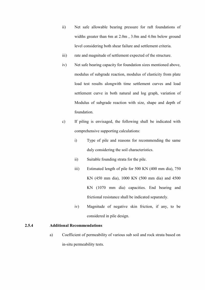
ii) Net safe allowable bearing pressure for raft foundations of
widths greater than 6m at 2.0m , 3.0m and 4.0m below ground
level considering both shear failure and settlement criteria.
iii) rate and magnitude of settlement expected of the structure.
iv) Net safe bearing capacity for foundation sizes mentioned above,
modulus of subgrade reaction, modulus of elasticity from plate
load test results alongwith time settlement curves and load
settlement curve in both natural and log graph, variation of
Modulus of subgrade reaction with size, shape and depth of
foundation.
c) If piling is envisaged, the following shall be indicated with
comprehensive supporting calculations:
i) Type of pile and reasons for recommending the same
duly considering the soil characteristics.
ii) Suitable founding strata for the pile.
iii) Estimated length of pile for 500 KN (400 mm dia), 750
KN (450 mm dia), 1000 KN (500 mm dia) and 4500
KN (1070 mm dia) capacities. End bearing and
frictional resistance shall be indicated separately.
iv) Magnitude of negative skin friction, if any, to be
considered in pile design.
2.5.4 Additional Recommendations
a) Coefficient of permeability of various sub soil and rock strata based on
in-situ permeability tests.
b) Cone resistance, frictional resistance, total resistance, relation between
cone resistance and Standard Penetration Test N Value, and settlement
analysis for different sizes of foundation as specified based on static
cone penetration test.
c) Electrical resistivity of sub-soil based electrical resistivity tests
including electrode spacing vs cumulative resistivity curve.
d) Suitability of the soil for construction of roads and pavements, their
stable slopes for shallow and deep excavations, active and passive
earth pressures at rest and modulus of elasticity as a function of depth
for the design of underground structures.
e) Suitability of locally available soils at site for filling and back filling
purposes.
f) If expansive soil is met with, recommendation on removal or
retainment of the same under the foundation etc. shall be given. In the
latter case, detailed specifications of any special treatment required
including specifications for materials to be used, construction method,
equipments to be deployed, etc. shall be furnished.
g) Protective measures based on chemical nature of soil and ground water
with due regard to potential deleterious effects on concrete, steel and
other building materials, etc. Remedial measures for sulphate attack
and acidity shall be dealt in detail. Susceptibility of soil to termite
action and remedial measures for the same.
h) Susceptibility of sub soil strata to liquifaction in the event of
earthquake. If so, recommendation for remedial measures.
i ) Any other information of special significance like dewatering schemes,
etc. which may have a bearing on the design and construction ,
j) Recommendations for additional soil investigation beyond the scope of
the present work if the Contractor considers such investigation is
necessary.
2.6 Rates and Measurements
Back to contents page
The clauses below shall apply for item rate contracts only. They shall not be
applicable to turn key and lumpsum contracts, except for work beyond the
scope of such contracts.
2.6.1 Rates
a) The item of work in the Schedule of Quantities describes the work very
briefly. The various items of the Schedule of Quantities shall be read in
conjunction with the corresponding sections in the technical
specifications including amendments and additions, if any. For each
item in the Schedule of Quantities, the bidder's rates shall include for
the activities covered in the description of the item as well as for all
necessary operations in details described in this technical specification.
b) The unit rates quoted shall include minor details which are obviously
and fairly intended, and which may not have been included in these
documents but are essential for the satisfactory completion of the work.
c) The bidders quoted rates shall be inclusive of providing all plant
equipments, men, materials, skilled and unskilled labour; making
observations establishing the ground level and coordinates at location
of each borehole, test pit, etc. by carrying levels from one established
bench mark and distances from one set of grid lines furnished by the
Owner. Also, no extra payments shall be made for conducting the
Standard Penetration Test; collecting, packing, transporting of all
samples and cores; recording of all results and submitting them in
approved formats.
d) No claims shall be entertained if the details are shown on the released
for construction drawings differ in any way (e.g .location and depth for
tests, number of tests, etc.) from those shown on the tender drawings.
2.6.2 Measurements
a) All measurements shall be in SI Units.
b) Lengths shall be measured in meters (m) correct to two places of
decimals. Areas shall be worked out in square meters (m2) and volume
in cubic meters and which may not have been included in these
documents but are essential for the satisfactory completion of the work.
c) The bidders quoted rates shall be inclusive of providing all plant
equipments, men, materials, skilled and unskilled labour; making
observations establishing the ground level and coordinates at location
of each borehole, test pit, etc. by carrying levels from one established
bench mark and distances from one set of grid lines furnished by the
Owner. Also, no extra payments shall be made for conducting the
Standard Penetration Test; collecting, packing, transporting of all
samples and cores; recording of all results and submitting them in
approved formats.
d) No claims shall be entertained if the details are shown on the released
for construction drawings differ in any way (e.g. location and depth for
tests, number of tests, etc.) from those shown on the tender drawings.
2.6.2 Measurements
a ) All measurements shall be in SI Units
b) Lengths shall be measured in meters (m) correct to two places of
decimals. Areas shall be worked out in square meters (m2) and volume
in cubic meters (m3), rounded off to two decimals.
c) Certain tests have to be conducted in bore holes, trial pits, etc. Such
boreholes, trial pits, etc., shall be measured only once and not again
just because of a tests are conducted therein.
2.7 Specific Requirements for Geotechnica1 investigation at River Crossings
Back to contents page
The entire soil investigation work shall be carried ~ out in accordance with the
relevant parts of the specification for geotechnical investigation. Standard
Penetration test at River Crossings and special locations shall be carried out at
the interval of 2.0, 3.0, 5.0, 7.0, 10.0 and thereafter at the rate of 3m intervals
to 40m. However in each bore holes undisturbed samples shall be collected at
every change of strata and at depths as follows: 1.0m, 4.0m, 7.0m, 11.0m and
thereafter at the rate of 3m intervals up to 38m. The spacing between the top
levels of undisturbed sampling and standard, penetration testing shall not be
less than 1.0m. The boreholes shall generally be executed to, specified depth
as per specifications or as shown in the drawing. If refusal strata is reached
(i.e. SPT-N Value is greater than 100 continuously for 5m depth) the borehole
may be terminated at shallower depth i.e. at 5m in refusal strata.
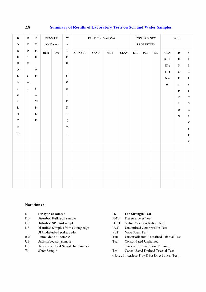
2.8 Summary of Results of Laboratory Tests on Soil and Water Samples
B
O
R
E
H
O
L
E/
T
RI
A
L
PI
T
N
O.
D
E
P
T
H
(
m
)
T
Y
P
E
O
F
S
A
M
P
L
E
DENSITY
(KN/Cu.m.)
Bulk Dry
W
A
T
E
R
C
O
N
T
E
N
T
(
%
)
PARTICLE SIZE (%) CONSISTANCY
PROPERTIES
SOIL
GRAVEL SAND SILT CLAY L.L. P.L. P.I. CLA
SSIF
ICA
TIO
N –
IS
D
E
S
C
R
I
P
T
I
O
N
S
P
E
C
I
F
I
C
G
R
A
V
I
T
Y
Notations :
I. For type of sample II. For Strength TestDB Disturbed Bulk Soil sample PMT Pressuremeter TestDP Disturbed SPT soil sample SCPT Static Cone Penetration TestDS Disturbed Samples from cutting edge UCC Unconfined Compression Test
Of Undisturbed soil sample VST Vane Shear TestRM Remoulded soil sample Tuu Unconsolidated Undrained Triaxial TestUB Undisturbed soil sample Tcu Consolidated UndrainedUS Undisturbed Soil Sample by Sampler Triaxial Test with Pore PressureW Water Sample Ted Consolidated Drained Triaxial Test
(Note : 1. Replace T by D for Direct Shear Test)
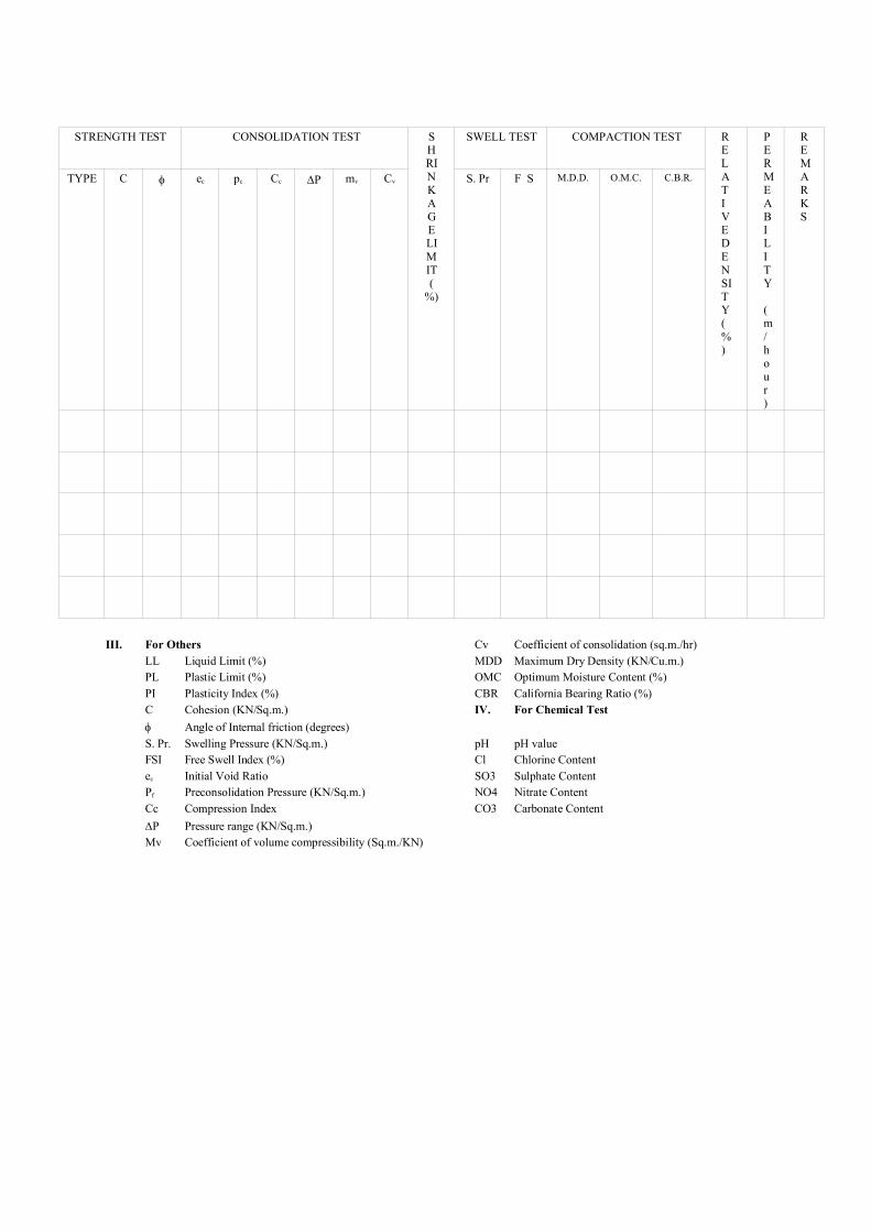
STRENGTH TEST CONSOLIDATION TEST
TYPE C ec pc Cc P mv Cv
SHRINKAGELIMIT(
%)
SWELL TEST COMPACTION TEST
S. Pr F S M.D.D. O.M.C. C.B.R.
RELATIVEDENSITY(%)
PERMEABILITY (m/hour)
REMARKS
III. For Others Cv Coefficient of consolidation (sq.m./hr)LL Liquid Limit (%) MDD Maximum Dry Density (KN/Cu.m.)PL Plastic Limit (%) OMC Optimum Moisture Content (%)PI Plasticity Index (%) CBR California Bearing Ratio (%)C Cohesion (KN/Sq.m.) IV. For Chemical Test Angle of Internal friction (degrees)S. Pr. Swelling Pressure (KN/Sq.m.) pH pH valueFSI Free Swell Index (%) Cl Chlorine Contentec Initial Void Ratio SO3 Sulphate ContentPf Preconsolidation Pressure (KN/Sq.m.) NO4 Nitrate ContentCc Compression Index CO3 Carbonate ContentP Pressure range (KN/Sq.m.)Mv Coefficient of volume compressibility (Sq.m./KN)
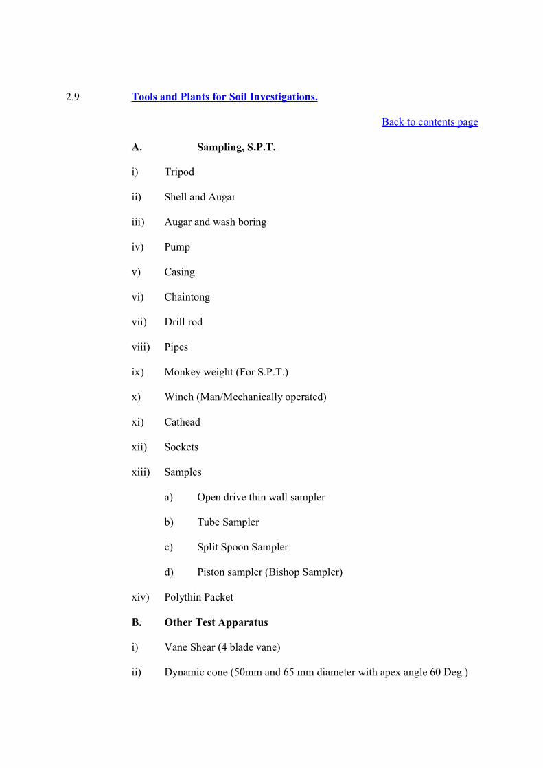
2.9 Tools and Plants for Soil Investigations.
Back to contents page
A. Sampling, S.P.T.
i) Tripod
ii) Shell and Augar
iii) Augar and wash boring
iv) Pump
v) Casing
vi) Chaintong
vii) Drill rod
viii) Pipes
ix) Monkey weight (For S.P.T.)
x) Winch (Man/Mechanically operated)
xi) Cathead
xii) Sockets
xiii) Samples
a) Open drive thin wall sampler
b) Tube Sampler
c) Split Spoon Sampler
d) Piston sampler (Bishop Sampler)
xiv) Polythin Packet
B. Other Test Apparatus
i) Vane Shear (4 blade vane)
ii) Dynamic cone (50mm and 65 mm diameter with apex angle 60 Deg.)
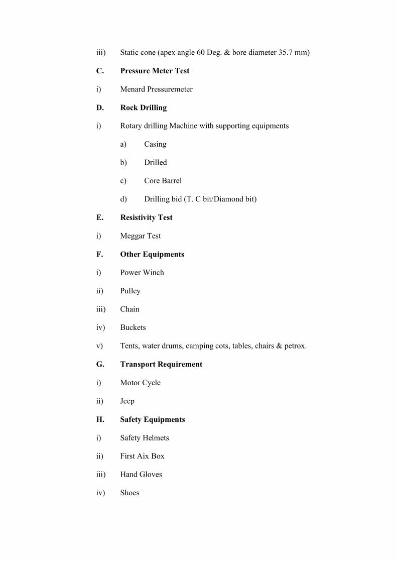
iii) Static cone (apex angle 60 Deg. & bore diameter 35.7 mm)
C. Pressure Meter Test
i) Menard Pressuremeter
D. Rock Drilling
i) Rotary drilling Machine with supporting equipments
a) Casing
b) Drilled
c) Core Barrel
d) Drilling bid (T. C bit/Diamond bit)
E. Resistivity Test
i) Meggar Test
F. Other Equipments
i) Power Winch
ii) Pulley
iii) Chain
iv) Buckets
v) Tents, water drums, camping cots, tables, chairs & petrox.
G. Transport Requirement
i) Motor Cycle
ii) Jeep
H. Safety Equipments
i) Safety Helmets
ii) First Aix Box
iii) Hand Gloves
iv) Shoes
NOTE :
a) The quantities and capacities of the equipments will depend upon the nos. of
bore hole, depth of the bore hole and completion schedule.
b) Additional equipments may be required depending upon site conditions.
3.0 Guidelines for Conducting Soil Investigation in Transmission Line
Back to contents page
Provision is made in Tower Package Specification for conducting soil
investigation at various tower locations. However, it was observed in past that
there were doubts about the selection of locations for conducting soil
investigation. In view of the above to facilitate the procedure, the locations
where the soil investigation is to be conducted are described below :
The soil investigation is to be conducted at the following locations :
1. Fissured rock is encountered with sub-soil water within 1.5 meter
depth from ground level.
2. Hard rock in combination with sub-soil water within 1.5 meter depth
from ground level.
3. Fissured rock in combination with water is encountered at the bottom
of the pit with black cotton soil at top.
4. Hard rock is encountered at the bottom with water and black cotton
soil at top.
5. Dry pure sand encountered in the pit.
6. Predominantly silty sand mixed with clay or other soils (without sub-
soil water).
7. Pure sand encountered with sub-soil water.
8. Predominantly silty sand mixed with clay or othersoils encountered
with sub-soil waters.
9. Pure clay encountered with sub-soil water.
10. If soil considered bad/trencherous.
11. At the locations falling in back waters of a tank or reservoirs where
there will be stagnation of water.
12. River crossing locations.
13. Tower used with 18M/25M extensions for power line crossings.
14. Railway crossings.
Soil investigation may be done at the locations mentioned above. It is
not required to be done at the locations wherever soil could be easily
classified and one of standard approved types of foundations could be
adopted.
SECTION-II
Tower Foundation
CHAPTER-1
General
___________________________________________________________________________
CHAPTERONE
___________________________________________________________________________
GENERAL
Back to contents page
1.0 Tower Foundations
Back to contents page
The tower foundations cost approx. 10 to 30 percent of overall cost of tower,
or 5 to 15 percent of the cost of transmission lines, depending on the type of
soil.
Experience shows that while an inadequate foundation may lead to collapse of
tower, an over design may prove very uneconomical. It is a good practice to
check the tower for permissible deflection at the top. Since differential
foundation settlement also causes tower deflection at the top, and if the total
deflection at the top of the tower is to be restricted, the permissible deflection
has to be carefully apportioned between the structure deflection and that
caused by the differential foundation settlement.
The design of a safe and economical foundation is based on soil properties,
knowledge of soil structure interaction and settlement analysis of tower
foundation.
1.1 Loads, Safety Factors and Settlement
Back to contents page
1.1.1 Loads
The loads on foundation are determined from an analysis of the tower. The
foundation is called upon to resist the following types of forces :
(i) Uplift
(ii) Downwards
(iii) Lateral load and
(iv) Overturning moment
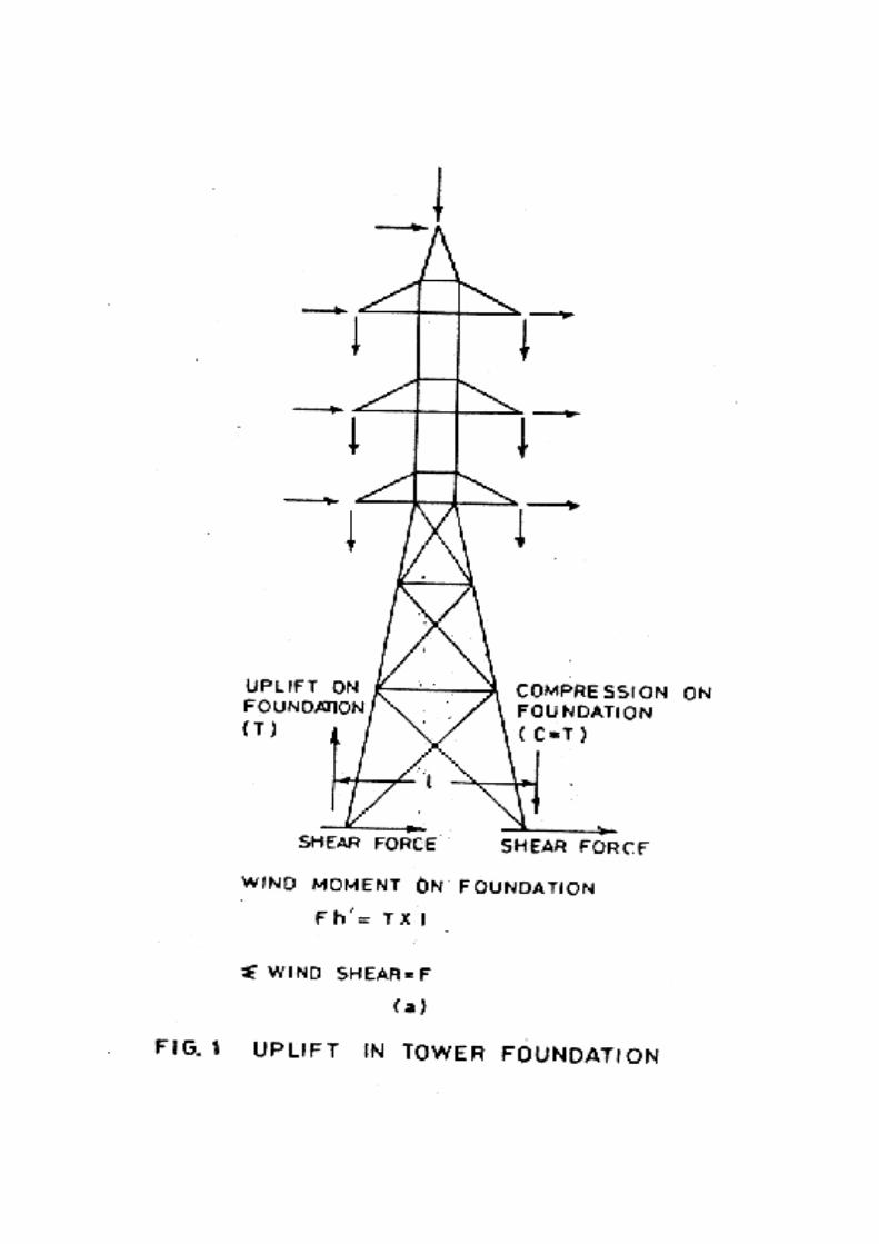
The basic vertical forces are derived from the deadweight of the tower and the
conductors. The wind contributes to the horizontal force on the tower,
producing not only shear force (lateral load) on the foundation, but also an
uplift on the windward side of the structure and a downthrust on the other. The
uplift or the compression forces are of primary concern in tower foundation
design as shown in fig. l. In the case of the heavy angle and terminal
structures, however, one pair of legs will be permanently subjected to
compression and the other pair to uplift, due to the permanent heavy loads
imposed by the deviation of the line. In this case, it is the general practice to
design all the four footings to withstand both types of loading.
1.1.2 Safety Factors
The foundations are generally designed for factor of safety which are 10 percent in excess of
those adopted for towers. Accordingly, the overload factors assumed in the design are 2.2
under normal conditions and 1.65 under broken-wire conditions. However, IS:802-1977 (Part
III), relating to transmission line tower foundations, does not make any distinction with regard
to factors of safety as between towers and foundations.
1.2 Classification of Soils
Back to contents page
The design of the tower foundation depends on the nature of loading and the
type of soil that supports the foundation. The soils are broadly classified as:
i) Sandy soil (loose, medium and dense),
ii) Clayey soil (soft, medium and stiff),
iii) Clayey sand (sandy clays, silty clays, clayey and silty sand), mixed soil.
iv) Rock (soft, medium and hard)
The following laboratory tests are usually conducted from the soil samples
collected:
i) Visual examination and other identification tests.
ii) Determination of in-situ density (r).
iii) Determination of strength parameters, namely, cohesion C and angle of
internal friction 0, settlement characteristic such as rate of settlement
(D/t), compression index Cc etc. and
iv) Determination of; elastic properties-Modulus of compressibility (k),
coefficient of lateral subgrade reaction (C), etc.
Among the field tests, the Standard Penetration Test (SPT) is extensively
adopted. In the Standard Penetration Test (SPT), a 64 Kg weight is dropped
76 cm to drive a sampling spoon into the ground. The no. of blows required to
push the spoon to a given depth is corelated with a no. of soil properties. The
advantage of SPT is that it is relatively quick, simple and inexpensive; but it is
also subjected to many kind of errors. Also, correlations of SPT measurements
with those of soil stress and other parameters are not particularly reliable.
In the Standard Core Penetration test, a shaft with a conical tip is slowly
pushed into the ground while electrical transducers measure both tip pressure
and side friction. The SCPT generally gives more accurate measurement than
the SPT. It is also a faster method to identify problem soils.
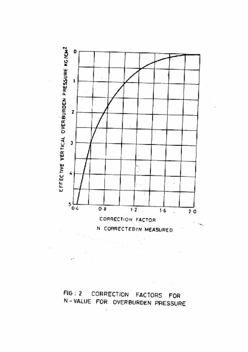
The SPT value N obtained from the field, is corrected for overburden pressure
in accordance with the chart shown in Fig. 2. The SCPT gives the point
resistance qc and side friction fc.
The SPT value N and the SCPT value qc are related as shown in table (1)
below. Table (1) - Correlation between SPT value N and SCPT value qc
Soil Type q/n
Clays 2.0
Silt, sandy silt and slightly cohesive silt and mixture 2.0
Clean fine to medium sands and slightly silty sands
Coarse
3-4
Sands and sands with little gravel 3-6
Sandy gravels and gravel 8-10
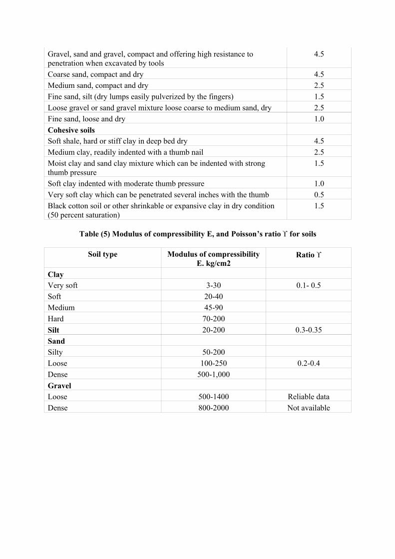
1.3 Properties of Soil
Back to contents page
The following soil properties are used in the design of different type of
foundations:
1. Density
2. Relative density Dr
3. Angle of internal friction for sandy soil
4. Unconfined compressive strength Cu and cohesion C for clayey soil.
5. Modules of compressibility Es
6. Coefficient of lateral subgrade modules (C for sand and k for clay)
7. Poisson's Ratio n

8. Compressive strength of rocks s
9. Ultimate bond strength of rock-anchor interface.
Table below gives the above properties and classify the soils and rocks.
1.4 Data For Foundation Design
Back to contents page
The following data are usually required for a proper selection of type of
foundation, its design and construction:
1. Route map showing proposed layout of tower and topography.
2. Selection of soil pits for soil data.
3. Selection of sites for SPT.
4. General layout of the tower and the loads at the foundation level.
5. Meteorological data " wind, earthquake and frost penetration
particulars.
6. Max. allowable settlement at the base of the tower considering the
permissible deflection at the top as H/140.
7. In the case of river crossings:
a. A site plan with details of crossing of at least 90m upstream and
downstream from the central line of the crossing.
b. Outline of banks.
c. Direction of flow of water.
d. Alignment of crossing and location of towers.
e. A cross section of the river at the proposed site of crossing, showing
bed-line, banks, ordinary flood level, low water level, the highest
flood, estimated depth of scour etc.
f. The maximum and mean velocity of water current.
Notes:
1. For non-cohesive soils the value of safe bearing capacity are to be
reduced by 50 percent if the water table is above or near the base of
footing.
2. The values of safe bearing capacities do not take into effect the shape
and size of footing, cohesion C, angle of internal friction 0, effect of
eccentricity, the SPT value N, etc. Hence, the values are to be
considered as average and approximate.
3. For other types of soil such as black cotton and peat, soil investigations
have to be necessarily carried out for determining the safe bearing
capacity.
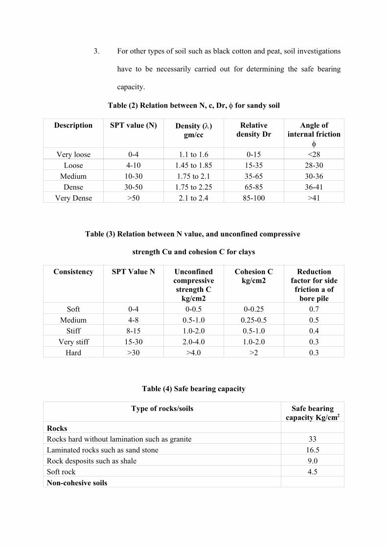
Table (2) Relation between N, c, Dr, for sandy soil
Description SPT value (N) Density ()gm/cc
Relativedensity Dr
Angle ofinternal friction
Very loose 0-4 1.1 to 1.6 0-15 <28
Loose 4-10 1.45 to 1.85 15-35 28-30Medium 10-30 1.75 to 2.1 35-65 30-36Dense 30-50 1.75 to 2.25 65-85 36-41
Very Dense >50 2.1 to 2.4 85-100 >41
Table (3) Relation between N value, and unconfined compressive
strength Cu and cohesion C for clays
Consistency SPT Value N Unconfinedcompressivestrength C
kg/cm2
Cohesion Ckg/cm2
Reductionfactor for sidefriction a of
bore pileSoft 0-4 0-0.5 0-0.25 0.7
Medium 4-8 0.5-1.0 0.25-0.5 0.5Stiff 8-15 1.0-2.0 0.5-1.0 0.4
Very stiff 15-30 2.0-4.0 1.0-2.0 0.3Hard >30 >4.0 >2 0.3
Table (4) Safe bearing capacity
Type of rocks/soils Safe bearingcapacity Kg/cm2
RocksRocks hard without lamination such as granite 33Laminated rocks such as sand stone 16.5Rock desposits such as shale 9.0Soft rock 4.5Non-cohesive soils
Gravel, sand and gravel, compact and offering high resistance topenetration when excavated by tools
4.5
Coarse sand, compact and dry 4.5Medium sand, compact and dry 2.5Fine sand, silt (dry lumps easily pulverized by the fingers) 1.5Loose gravel or sand gravel mixture loose coarse to medium sand, dry 2.5Fine sand, loose and dry 1.0Cohesive soilsSoft shale, hard or stiff clay in deep bed dry 4.5Medium clay, readily indented with a thumb nail 2.5Moist clay and sand clay mixture which can be indented with strongthumb pressure
1.5
Soft clay indented with moderate thumb pressure 1.0Very soft clay which can be penetrated several inches with the thumb 0.5Black cotton soil or other shrinkable or expansive clay in dry condition(50 percent saturation)
1.5
Table (5) Modulus of compressibility E, and Poisson’s ratio for soils
Soil type Modulus of compressibilityE. kg/cm2
Ratio
ClayVery soft 3-30 0.1- 0.5Soft 20-40Medium 45-90Hard 70-200Silt 20-200 0.3-0.35SandSilty 50-200Loose 100-250 0.2-0.4Dense 500-1,000GravelLoose 500-1400 Reliable dataDense 800-2000 Not available

CHAPTER-2
Types of Foundations
___________________________________________________________________________
CHAPTERTWO
___________________________________________________________________________
TYPES OF FOUNDATIONS
Back to contents page
2.0 Introduction
Back to contents page
The foundation are classified as shallow or deep based on Df/B ratio
Where Df = Depth of foundation and B = Breadth of foundation
If Df / B<l, then the foundation is considered shallow and if Df / B>l, it is
classified as a deep foundation. Piles are classified as deep foundation. Even
though footing may have greater depth than the breadth in some
circumstances, they are Created as shallow foundations for the analysis of
bearing capacity. This approximation leads to a conservative estimate of the
factor of safety and is, therefore, adopted for convenience and ease in
calculations.
2.1 Types of Foundation
Back to contents page
This foundation work requiring excavation and backfill operation is quite
satisfactory from design point of view. The knowledge of soil mechanics and
the necessity of erecting towers on a variety of soils have made it possible and
necessary for the designer to adopt new innovations and techniques. As a
result several types of tower foundations have been derived and successfully
used. Some of the more common types of foundation, mainly for broad based
towers are briefly described below.
(a) Concrete Pad and Chimney type (Fig.3)
This is the most common type of footing used in India and some
countries of the continent. It consists of a plain concrete footing pad,
the size and depth of which are decided either on the basis of bearing
area necessary for transmission of vertical downward load or from
consideration of the amount of holding power required to resist the
uplift force. The stub angle is taken inside and effectively anchored to
the bottom pad by cleat angle and keying rods; and the muff or the
chimney with stub angle inside works as a composite member. The
pad may be either pyramidal (Fig.3a) or stepped (Fig.3b).
(b) Steel Grillage (Fig.4)
Steel grillage can be of various designs. Generally it consists of a layer
of steel beam as pad for the tower leg by means of heavier joints or
channels resting cross-ways on the bearing beams.
Grillage footings require much more steel than a comparable concrete
footing but erection cost is only a fraction of that of the concrete
footing resulting in often economical and always quicker construction.
Other advantages are that the complete foundation can be purchased
from the manufacturer of towers alongwith the tower members.
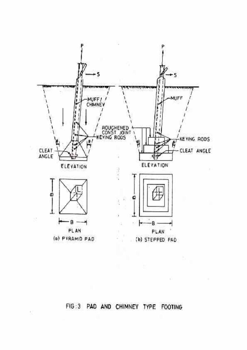

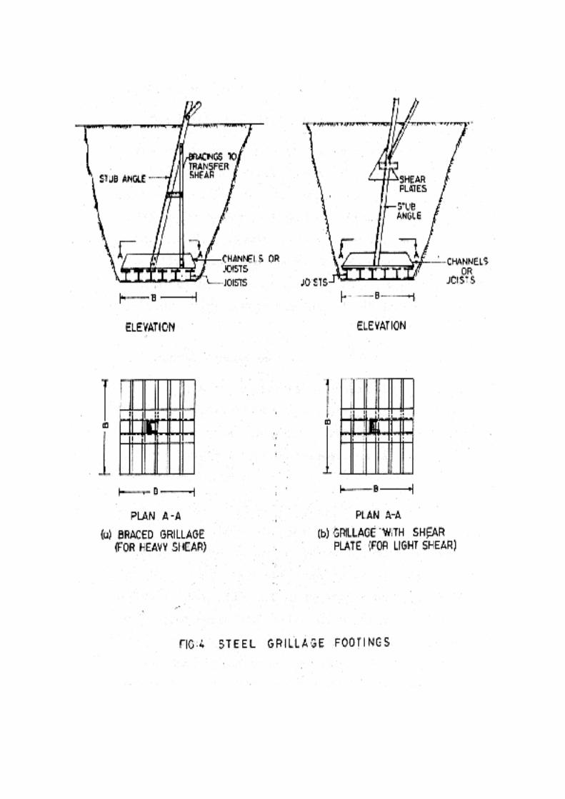
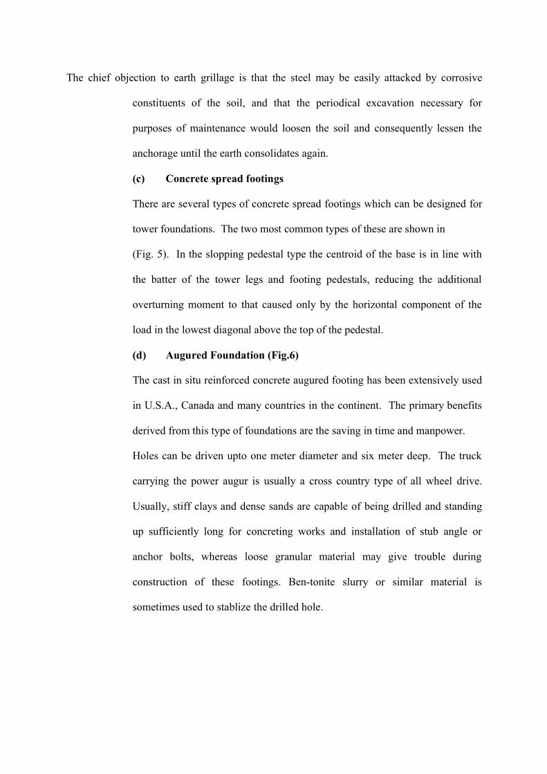
The chief objection to earth grillage is that the steel may be easily attacked by corrosive
constituents of the soil, and that the periodical excavation necessary for
purposes of maintenance would loosen the soil and consequently lessen the
anchorage until the earth consolidates again.
(c) Concrete spread footings
There are several types of concrete spread footings which can be designed for
tower foundations. The two most common types of these are shown in
(Fig. 5). In the slopping pedestal type the centroid of the base is in line with
the batter of the tower legs and footing pedestals, reducing the additional
overturning moment to that caused only by the horizontal component of the
load in the lowest diagonal above the top of the pedestal.
(d) Augured Foundation (Fig.6)
The cast in situ reinforced concrete augured footing has been extensively used
in U.S.A., Canada and many countries in the continent. The primary benefits
derived from this type of foundations are the saving in time and manpower.
Holes can be driven upto one meter diameter and six meter deep. The truck
carrying the power augur is usually a cross country type of all wheel drive.
Usually, stiff clays and dense sands are capable of being drilled and standing
up sufficiently long for concreting works and installation of stub angle or
anchor bolts, whereas loose granular material may give trouble during
construction of these footings. Ben-tonite slurry or similar material is
sometimes used to stablize the drilled hole.
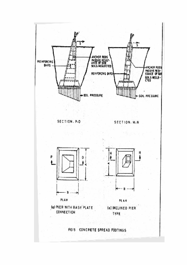
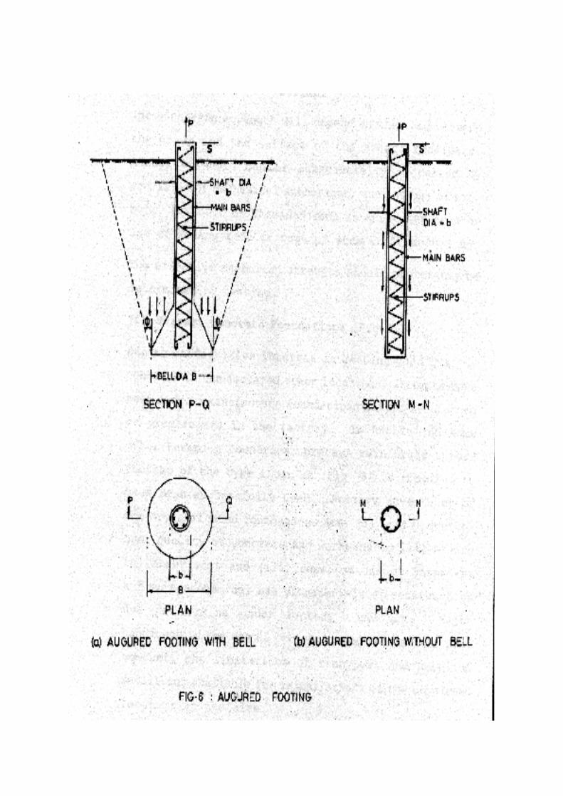
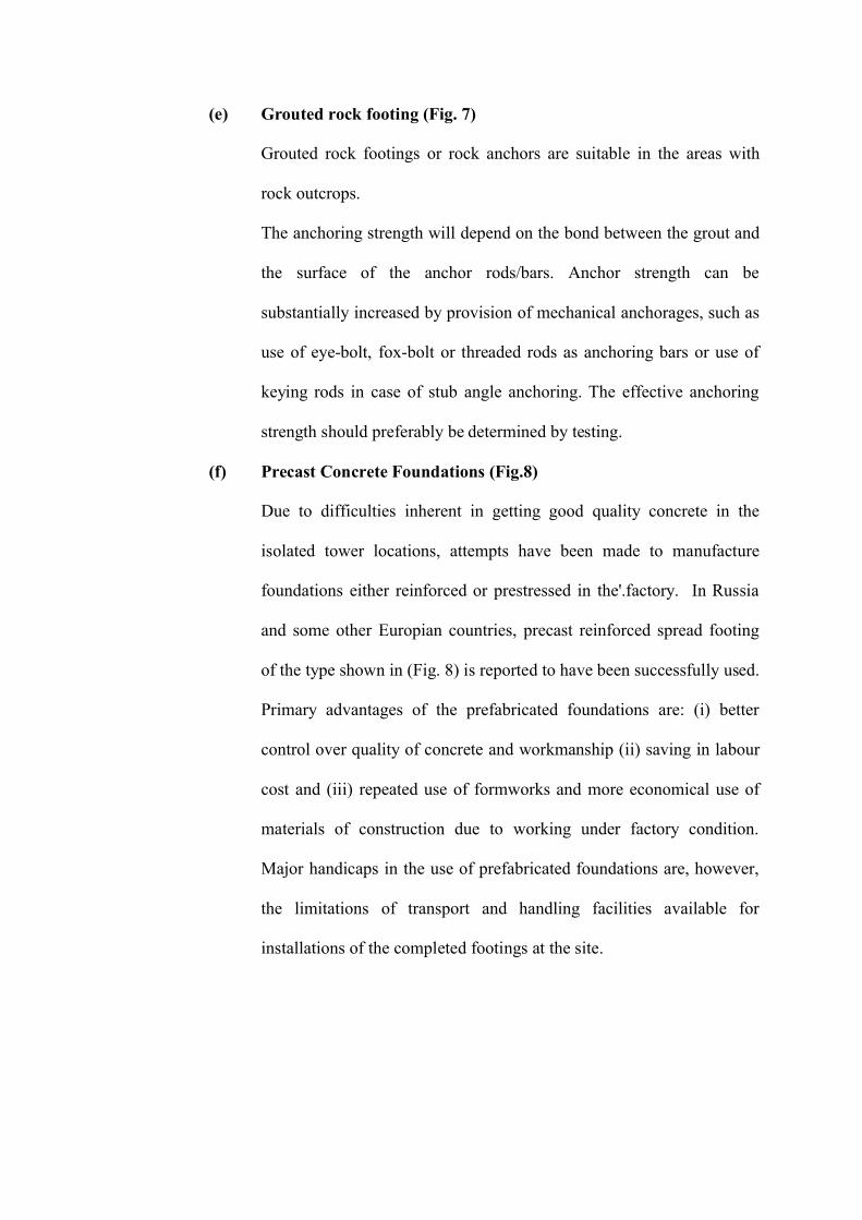
(e) Grouted rock footing (Fig. 7)
Grouted rock footings or rock anchors are suitable in the areas with
rock outcrops.
The anchoring strength will depend on the bond between the grout and
the surface of the anchor rods/bars. Anchor strength can be
substantially increased by provision of mechanical anchorages, such as
use of eye-bolt, fox-bolt or threaded rods as anchoring bars or use of
keying rods in case of stub angle anchoring. The effective anchoring
strength should preferably be determined by testing.
(f) Precast Concrete Foundations (Fig.8)
Due to difficulties inherent in getting good quality concrete in the
isolated tower locations, attempts have been made to manufacture
foundations either reinforced or prestressed in the'.factory. In Russia
and some other Europian countries, precast reinforced spread footing
of the type shown in (Fig. 8) is reported to have been successfully used.
Primary advantages of the prefabricated foundations are: (i) better
control over quality of concrete and workmanship (ii) saving in labour
cost and (iii) repeated use of formworks and more economical use of
materials of construction due to working under factory condition.
Major handicaps in the use of prefabricated foundations are, however,
the limitations of transport and handling facilities available for
installations of the completed footings at the site.
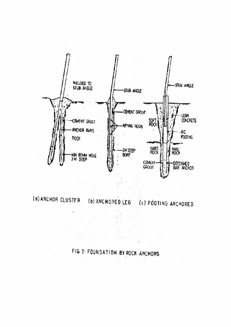
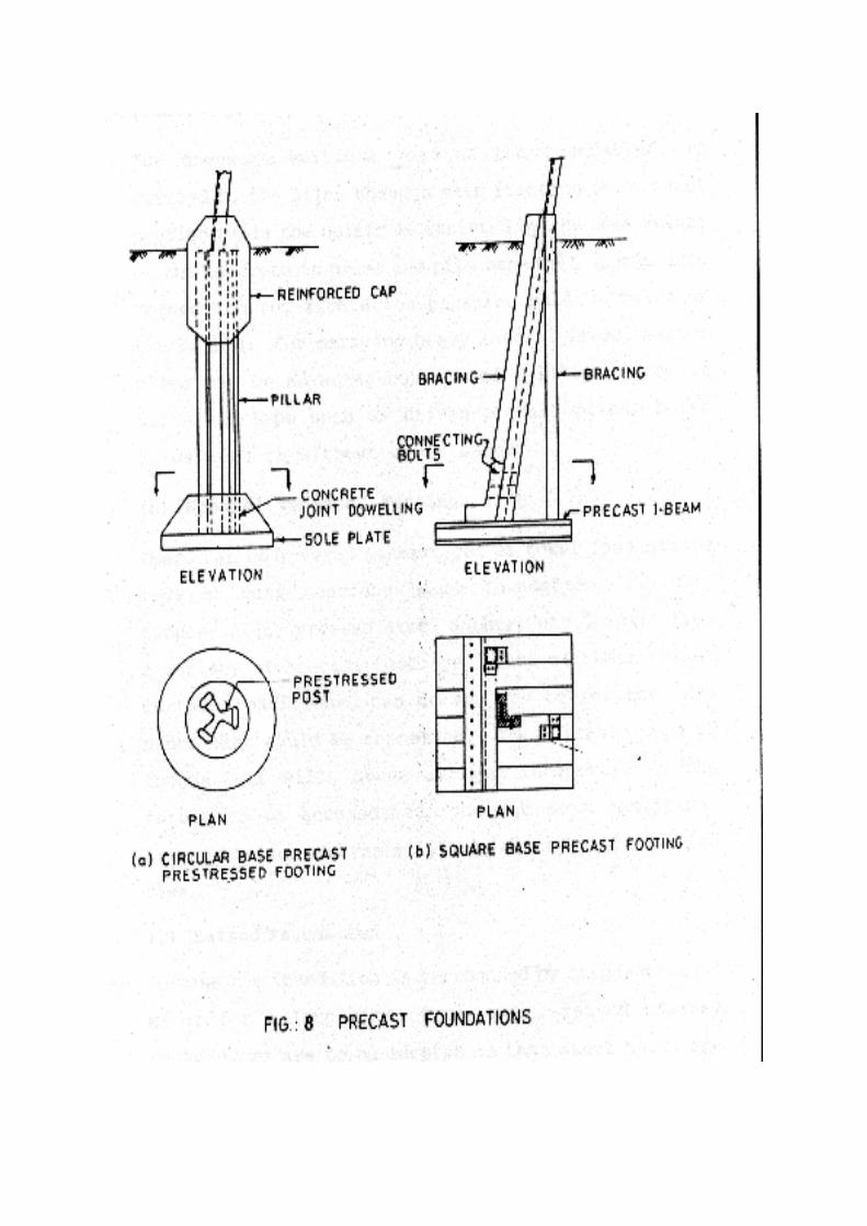
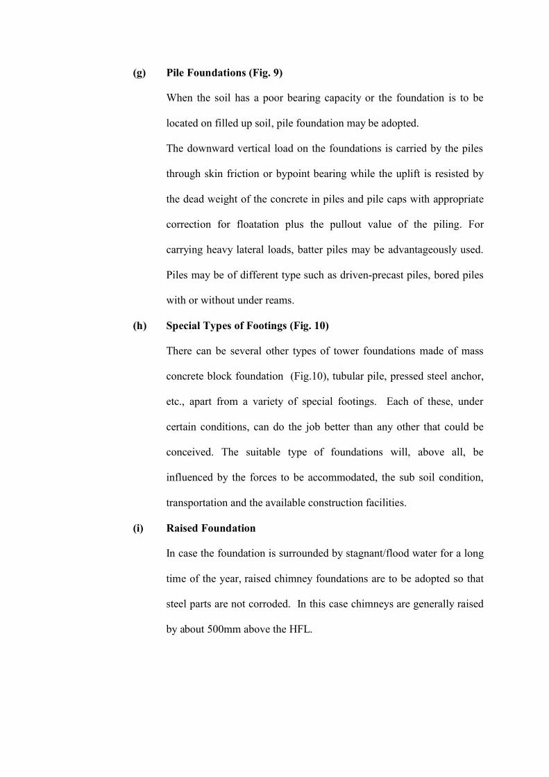
(g) Pile Foundations (Fig. 9)
When the soil has a poor bearing capacity or the foundation is to be
located on filled up soil, pile foundation may be adopted.
The downward vertical load on the foundations is carried by the piles
through skin friction or bypoint bearing while the uplift is resisted by
the dead weight of the concrete in piles and pile caps with appropriate
correction for floatation plus the pullout value of the piling. For
carrying heavy lateral loads, batter piles may be advantageously used.
Piles may be of different type such as driven-precast piles, bored piles
with or without under reams.
(h) Special Types of Footings (Fig. 10)
There can be several other types of tower foundations made of mass
concrete block foundation (Fig.10), tubular pile, pressed steel anchor,
etc., apart from a variety of special footings. Each of these, under
certain conditions, can do the job better than any other that could be
conceived. The suitable type of foundations will, above all, be
influenced by the forces to be accommodated, the sub soil condition,
transportation and the available construction facilities.
(i) Raised Foundation
In case the foundation is surrounded by stagnant/flood water for a long
time of the year, raised chimney foundations are to be adopted so that
steel parts are not corroded. In this case chimneys are generally raised
by about 500mm above the HFL.
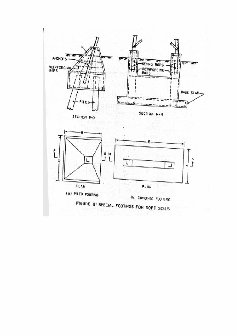
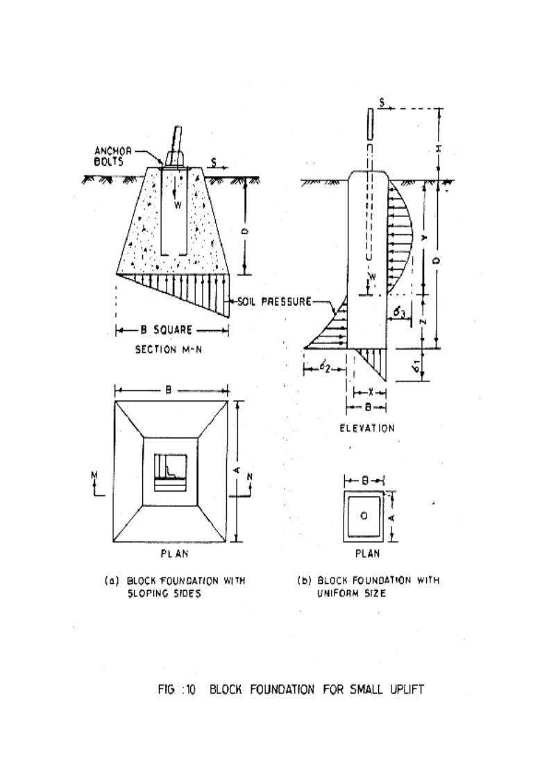
(j) Shallow Depth Foundation:
Whenever the normal depth foundations cannot be constructed at site
due to excessive seepage of heavy sub-soil water then reduced depth
foundations are to be adopted. However, in all above cases engg.
approval is prerequisite. In such locations soil investigation to be
carried out to ascertain the properties of the soil for the design of the
foundation.
CHAPTER-3
Classification and Stub Setting
___________________________________________________________________________
CHAPTERTHREE
___________________________________________________________________________
CLASSIFICATION AND STUB SETTING
Back to contents page
3.0 Line Construction
Back to contents page
Transmission line construction comprises the following phases:
(i) Investigation and survey
(ii) Transportation
(iii) Foundations
(iv) Tower assembly
(v) Stringing
3.1 Investigation And Survey
Back to contents page
In the earlier section on line surveys, the various aspects relating to
investigation and survey have been covered in detail.
3.2 Transportation
Back to contents page
The weight of materials and equipment required for building a transmission
line tower may total several hundred tonnes, while construction sites are
usually scattered over a wide area. Logistic operations thus become a major
factor in these projects. Especially in mountainous terrain, road transportation
facilities are poor and effective temporary construction routes are limited. All
material transport shall be undertaken. in vehicles suitable for the purpose and
free from effect of any chemical substances. Tower members should be loaded
and transported in such a manner that these are not bent in transit and sharp
bend corners are not opened up or damaged.
3.3 Foundation
Back to contents page
The construction of tower foundations shall be in accordance with IS
4091:1979 and Power Grid specifications.
3.3.1 Check Survey
This will be conducted to make a check on detailed survey and to locate the
peg marks and the tower positions on ground conforming to the survey charts.
In the process it is necessary to have the pit centres marked according to the
excavation marking charts. The levels, up or down, of each pit centre with
respect to the centre of the tower location shall be noted and recorded for
determining the amount of benching or earthwork required to meet design
requirements of the foundation.
If the levels of the pit centres be in sharp contrast with the level of the tower
centre (say beyond a slope of 1:4), suitable "leg extension" may be deployed as
required.
3.4 Preparation of Foundation Site
Back to contents page
3.4.1 After tower spotting is done during check survey, it is often the case that the
area within the base of the tower is found uneven in level. Minor variation in
level can be ignored but variations in level of more than 60 cms are to be dealt
with benching the area to the reference level of centre peg. The foundation
shall be placed at the design depth with reference to the centre peg level. The
area below the centre peg shall be back filled to get a leveled surface. If the
level of back filling is considerably high, the filled area shall be enclosed by a
revetment wall to prevent erosion.
3.4.2 In Hilly areas the difference of levels in the four legs is generally very high
resulting in large quantity of benching and massive revetment walls, which
will be very uneconomical. In these cases special hillside extensions are
provided to place the four legs at different elevations.
3.5 Type of Foundation to be Adopted
Back to contents page
3.5.1 The following standard types of foundation are approved in Powergrid for
adoption in transmission lines for different towers:-
i) Normal dry
ii) Wet
iii) Partially submerged
iv) Fully submerged
v) Dry fissured rock
vi) Wet fissured rock
vii) Hard rock foundation.
viii) Black cotton soil foundation
3.5.2 The above foundations are designed for the corresponding predominantly
prevalent soils in the pits. However, there will be cases where a combination
of soils in the pits may be observed and correct classification of the standard
foundations is required to be done.
3.5.3 Type of foundations to be adopted with reference to the soils and sub-soils
waters encountered in the pits are indicated in Table-1 to 3. Foundations may
be classified and adopted accordingly. In certain classifications of soils with
sub-soil waters (items 6(b) and 7(b) of Table-1, items 1(b) and 2(c) of table 2
and items 1,2 & 3 of Table 3) standard foundations cannot straight away be
adopted.
3.5.4 If the soil conditions differ with the four legs of the same tower necessitating
adopting of different types of approved foundation for the different legs of the
tower, classification of foundations may be done for each of the pits as
required by the actual soil conditions in the pits.
3.5.5 If site feels that soil encountered at any of the locations do not tally with the
description of soils given in the Annexure enclosed or if the soils are
considered very bad/tracherous, foundations may not be decided at such
locations by the site. Classification of the foundations of such locations may
be done in consultation with Corporate Engineering department. If the
locations fall in the back water of any river, tank or reservoir, the depth of the
back water at those locations and the duration of the stagnation of water at
those locations is to be ascertained and foundation to be decided after studying
the detailed soil report.
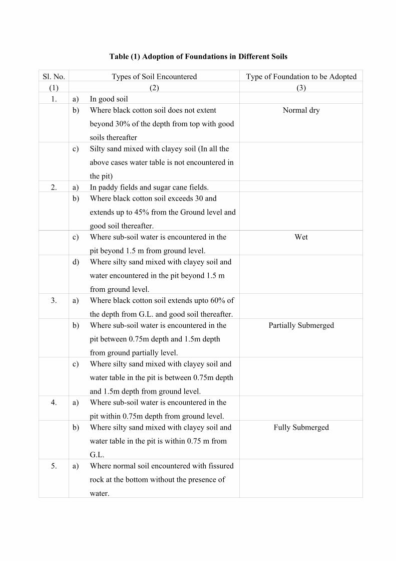
Table (1) Adoption of Foundations in Different Soils
Sl. No. Types of Soil Encountered Type of Foundation to be Adopted(1) (2) (3)1. a) In good soil
b) Where black cotton soil does not extent
beyond 30% of the depth from top with good
soils thereafter
Normal dry
c) Silty sand mixed with clayey soil (In all the
above cases water table is not encountered in
the pit)2. a) In paddy fields and sugar cane fields.
b) Where black cotton soil exceeds 30 and
extends up to 45% from the Ground level and
good soil thereafter.c) Where sub-soil water is encountered in the
pit beyond 1.5 m from ground level.
Wet
d) Where silty sand mixed with clayey soil and
water encountered in the pit beyond 1.5 m
from ground level.3. a) Where black cotton soil extends upto 60% of
the depth from G.L. and good soil thereafter.b) Where sub-soil water is encountered in the
pit between 0.75m depth and 1.5m depth
from ground partially level.
Partially Submerged
c) Where silty sand mixed with clayey soil and
water table in the pit is between 0.75m depth
and 1.5m depth from ground level.4. a) Where sub-soil water is encountered in the
pit within 0.75m depth from ground level.b) Where silty sand mixed with clayey soil and
water table in the pit is within 0.75 m from
G.L.
Fully Submerged
5. a) Where normal soil encountered with fissured
rock at the bottom without the presence of
water.
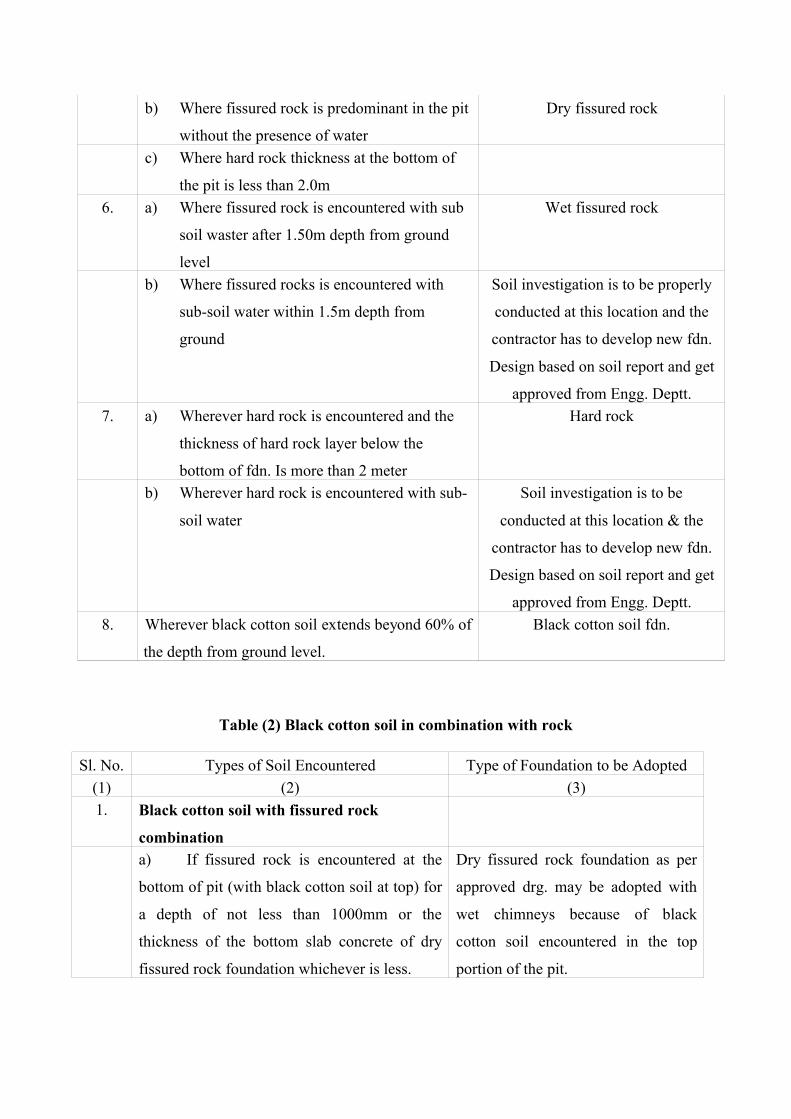
b) Where fissured rock is predominant in the pit
without the presence of water
Dry fissured rock
c) Where hard rock thickness at the bottom of
the pit is less than 2.0m6. a) Where fissured rock is encountered with sub
soil waster after 1.50m depth from ground
level
Wet fissured rock
b) Where fissured rocks is encountered with
sub-soil water within 1.5m depth from
ground
Soil investigation is to be properly
conducted at this location and the
contractor has to develop new fdn.
Design based on soil report and get
approved from Engg. Deptt.7. a) Wherever hard rock is encountered and the
thickness of hard rock layer below the
bottom of fdn. Is more than 2 meter
Hard rock
b) Wherever hard rock is encountered with sub-
soil water
Soil investigation is to be
conducted at this location & the
contractor has to develop new fdn.
Design based on soil report and get
approved from Engg. Deptt.8. Wherever black cotton soil extends beyond 60% of
the depth from ground level.
Black cotton soil fdn.
Table (2) Black cotton soil in combination with rock
Sl. No. Types of Soil Encountered Type of Foundation to be Adopted(1) (2) (3)1. Black cotton soil with fissured rock
combinationa) If fissured rock is encountered at the
bottom of pit (with black cotton soil at top) for
a depth of not less than 1000mm or the
thickness of the bottom slab concrete of dry
fissured rock foundation whichever is less.
Dry fissured rock foundation as per
approved drg. may be adopted with
wet chimneys because of black
cotton soil encountered in the top
portion of the pit.

b) If fissured rock in combination with
water is encountered at the bottom of the pit
with black cotton soil at the top.
Wet fissured rock foundation is to be
adopted.
2. Black Cotton Soil with hard Rock
Combinationa) If the hard rock is encountered at the
bottom of the pit (with black cotton soil at top)
and the thickness of the hard rock layer below
foundation is more than 2m.
Hard rock fdn. Design to be adopted
with wet chimneys because of the
black cotton soil encountered in the
top portion of the pit.b) If hard rock encountered at the bottom
of the pit with black cotton soil at the top and
hard rock layer depth is less than 2m.
Fissured rock foundation design to be
adopted with wet chimneys because
of the black cotton soil at the top.c) If hard rock is encountered at the
bottom with water and black cotton soil at top
and hard rock layer depth is less than 2m.
Wet fissured rock foundation as per
approved drgs. are to be adopted.
Table (3) Sand in Combination with Sub-soil water
Sl. No. Types of Soil Encountered Type of Foundation to be Adopted(1) (2) (3)1. Predominantly sand mixed with clay or other
soil (without sub-soil water)
Dry sandy soil foundation may be
adopted.2. Predominantly sand mixed with soils
encountered with sub soils water in the pits
FS/Wet sandy soil foundation may be
adopted depending on water table.3. Pure sand encountered with sub-soil water
inside the pit
Same as above
Table (4) Clay Mixed with Silty Sand
Sl. No. Types of Soil Encountered Type of Foundation to be Adopted(1) (2) (3)1. Pure clay encountered without water Dry black cotton foundation may be
adopted.
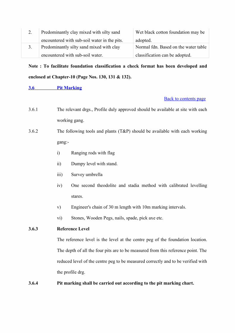
2. Predominantly clay mixed with silty sand
encountered with sub-soil water in the pits.
Wet black cotton foundation may be
adopted.3. Predominantly silty sand mixed with clay
encountered with sub-soil water.
Normal fdn. Based on the water table
classification can be adopted.
Note : To facilitate foundation classification a check format has been developed and
enclosed at Chapter-10 (Page Nos. 130, 131 & 132).
3.6 Pit Marking
Back to contents page
3.6.1 The relevant drgs., Profile duly approved should be available at site with each
working gang.
3.6.2 The following tools and plants (T&P) should be available with each working
gang:-
i) Ranging rods with flag
ii) Dumpy level with stand.
iii) Survey umbrella
iv) One second theodolite and stadia method with calibrated levelling
stares.
v) Engineer's chain of 30 m length with 10m marking intervals.
vi) Stones, Wooden Pegs, nails, spade, pick axe etc.
3.6.3 Reference Level
The reference level is the level at the centre peg of the foundation location.
The depth of all the four pits are to be measured from this reference point. The
reduced level of the centre peg to be measured correctly and to be verified with
the profile drg.
3.6.4 Pit marking shall be carried out according to the pit marking chart.
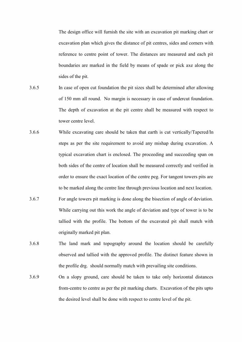
The design office will furnish the site with an excavation pit marking chart or
excavation plan which gives the distance of pit centres, sides and corners with
reference to centre point of tower. The distances are measured and each pit
boundaries are marked in the field by means of spade or pick axe along the
sides of the pit.
3.6.5 In case of open cut foundation the pit sizes shall be determined after allowing
of 150 mm all round. No margin is necessary in case of undercut foundation.
The depth of excavation at the pit centre shall be measured with respect to
tower centre level.
3.6.6 While excavating care should be taken that earth is cut vertically/Tapered/In
steps as per the site requirement to avoid any mishap during excavation. A
typical excavation chart is enclosed. The proceeding and succeeding span on
both sides of the centre of location shall be measured correctly and verified in
order to ensure the exact location of the centre peg. For tangent towers pits are
to be marked along the centre line through previous location and next location.
3.6.7 For angle towers pit marking is done along the bisection of angle of deviation.
While carrying out this work the angle of deviation and type of tower is to be
tallied with the profile. The bottom of the excavated pit shall match with
originally marked pit plan.
3.6.8 The land mark and topography around the location should be carefully
observed and tallied with the approved profile. The distinct feature shown in
the profile drg. should normally match with prevailing site conditions.
3.6.9 On a slopy ground, care should be taken to take only horizontal distances
from-centre to centre as per the pit marking charts. Excavation of the pits upto
the desired level shall be done with respect to centre level of the pit.

3.6.10 The excavated earth shall be dumped on the outer edges of the pits away from
the base of the tower to a minimum distance equal to the depth of the pit to
avoid collapse of the free standing sides of the pit during excavation or
concreting.
3.6.11 For the sake of reference the pits of the towers shall be designated as shown in
the figure (Fig. 11).
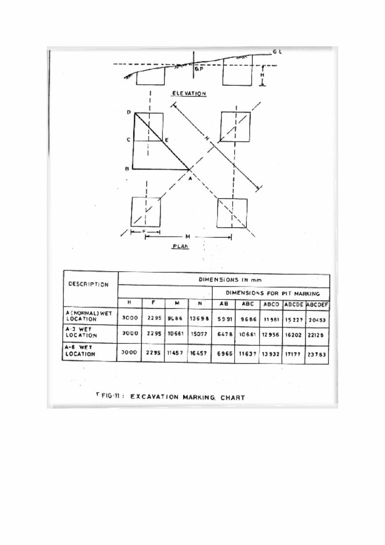
3.7 Shoring and Shuttering
Back to contents page
3.7.1 Shoring and shuttering shall be done keeping in view the requirements given
in IS 3764:1966
3.7.2 In pits excavated in sandy soil or water bearing strata and particularly black
cotton soil where there is every likelihood of pits collapsing, shoring and
shuttering, made out of timber planks 30-35 mm thickness or steel frames of
adequate strength to suit the requirement, will be provided.
3.7.3 Sand Bedding/stone bedding will be provided in foundations of marshy and
wet Black Cotton foundations.
3.8 Dewatering
Back to contents page
3.8.1 Dewatering shall be carried out manually or by mechanical means power
driven pumps to facilitate excavation and casting of foundation. The pumps
shall be suitable for handling mud water.
3.8.2 In areas where sub-soil water recoupment is heavy and where water cannot be
controlled even by use of power driven pumps well point system is used for
controlling water. In this system a grid of pipes are laid around the area where
the pits are excavated and the system is very effective in pumping operation.
The pit can be excavated avoiding risk of collapse of earth. This will ensure
proper quality of concreting.
3.8.3 Another method is by drilling bore holes of a deeper pit much below
foundation level for pumping out water by ordinary pumps. Number of
boreholes depend on the volume of sub soil water.
3.8.4 In areas where sub-soil water recoupment is very rapid and water cannot be
controlled, shallow foundations will be useful.
3.9 Excavation in Rock
Back to contents page
For excavation in hard rock, blasting can be resorted to. Reference shall be
made to statutory rules for blasting and use of explosives for this purpose. No
blasting is permitted near permanent work or dwellings. Blasting shall be so
made that pits are excavated as near to the designed dimensions as practicable.
3.9.1 The work of blasting in rock is carried out in three separate operations.
(a) Drilling of holes to hold explosive charge.
(b) Charging of the drilled holes
(c) Fixing the charge
(a) Drilling of Holes to hold explosive charge
i) Drilling of holes to hold the explosive charge may be done either
manually or with an air compressor as per the requirement at the site.
ii) The equipment for hand drilling is simple but requires more man hours
and generally consists of a set of Jumpers or Drills which are usually
made from 22 mm diameter hexagonal steel bars.
iii) The jumpers are 1m, 1.25m and 1.5m long and are suitably shaped.
They must be tempered when sharpened. A 2 Kg. hammer is used for
striking the jumper, which is given a slight rotation after each blow.
The rate of progress by this in hard rock is 25 to 41 cm per hour.
iv) When large quantity of rock is required to be excavated, an air
compressor is used for drilling the holes.
(b) Charging of the Drilled Holes
The charge consists of gelatine and detonator. Either half or a full gelatine is
used as per the requirement. Detonator is normally pressed into the gelatine
after making a hole in the gelatine with stick. Detonator is to be pressed into
the gelatine till it is completely embedded in the gelatine. Then this assembly
is placed into holes drilled.
(c) Fixing the Charge
The detonator leads are first interconnected to form a circuit and later the ends
of this circuit are connected to the exploder with separate wires. The exploder
is kept in a sheltered spot. To fire the shot the exploder handle is rotated at a
high speed.
3.9.2 Procedure in case of Misfired Shots
(i) The misfired shot should not be touched.
(ii) One should not approach a misfired shot until atleast 15 minutes have
elapsed and all connections and' handle removed from the exploder.
(iii) A second hole is to be drilled at a safe distance from the first in such a
direction as well to keep the boring tool clear of the hole.
(iv) Thus second hole is to be charged and fired.
(v) The debris is to be searched thoroughly for unexploded detonator.
3.9.3 Additional Precautions
To protect the persons and animals from injuries from flying debris depending
on situation the numbers of holes to be drilled should be less deep and the pit
should be covered with a steel plate. Such controlled blasting is an exception if
the transmission line is kept away from villages and inhabited areas.
3.10 Procedure for setting Stubs at site by Combined Stub Setting
Back to contents page
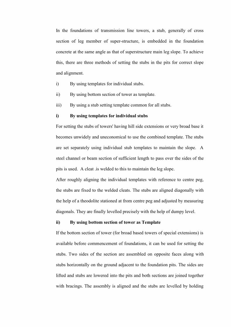
In the foundations of transmission line towers, a stub, generally of cross
section of leg member of super-structure, is embedded in the foundation
concrete at the same angle as that of superstructure main leg slope. To achieve
this, there are three methods of setting the stubs in the pits for correct slope
and alignment.
i) By using templates for individual stubs.
ii) By using bottom section of tower as template.
iii) By using a stub setting template common for all stubs.
i) By using templates for individual stubs
For setting the stubs of towers' having hill side extensions or very broad base it
becomes unwidely and uneconomical to use the combined template. The stubs
are set separately using individual stub templates to maintain the slope. A
steel channel or beam section of sufficient length to pass over the sides of the
pits is used. A cleat .is welded to this to maintain the leg slope.
After roughly aligning the individual templates with reference to centre peg,
the stubs are fixed to the welded cleats. The stubs are aligned diagonally with
the help of a theodolite stationed at from centre peg and adjusted by measuring
diagonals. They are finally levelled precisely with the help of dumpy level.
ii) By using bottom section of tower as Template
If the bottom section of tower (for broad based towers of special extensions) is
available before commencement of foundations, it can be used for setting the
stubs. Two sides of the section are assembled on opposite faces along with
stubs horizontally on the ground adjacent to the foundation pits. The sides are
lifted and stubs are lowered into the pits and both sections are joined together
with bracings. The assembly is aligned and the stubs are levelled by holding
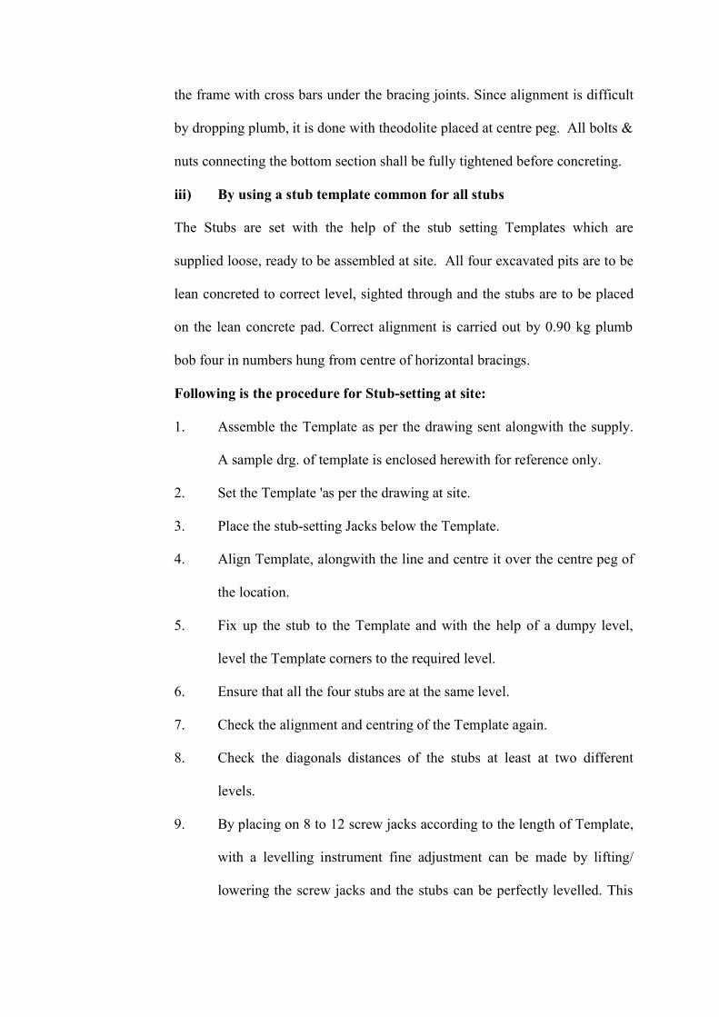
the frame with cross bars under the bracing joints. Since alignment is difficult
by dropping plumb, it is done with theodolite placed at centre peg. All bolts &
nuts connecting the bottom section shall be fully tightened before concreting.
iii) By using a stub template common for all stubs
The Stubs are set with the help of the stub setting Templates which are
supplied loose, ready to be assembled at site. All four excavated pits are to be
lean concreted to correct level, sighted through and the stubs are to be placed
on the lean concrete pad. Correct alignment is carried out by 0.90 kg plumb
bob four in numbers hung from centre of horizontal bracings.
Following is the procedure for Stub-setting at site:
1. Assemble the Template as per the drawing sent alongwith the supply.
A sample drg. of template is enclosed herewith for reference only.
2. Set the Template 'as per the drawing at site.
3. Place the stub-setting Jacks below the Template.
4. Align Template, alongwith the line and centre it over the centre peg of
the location.
5. Fix up the stub to the Template and with the help of a dumpy level,
level the Template corners to the required level.
6. Ensure that all the four stubs are at the same level.
7. Check the alignment and centring of the Template again.
8. Check the diagonals distances of the stubs at least at two different
levels.
9. By placing on 8 to 12 screw jacks according to the length of Template,
with a levelling instrument fine adjustment can be made by lifting/
lowering the screw jacks and the stubs can be perfectly levelled. This

ensures accurate verticality of the tower. For ensuring all towers in one
line and cross-armd at right angle to it, four plumb bobs should
dropped from the center of the horizontal members of the Template to
correspond to the cross pegs and alignment pegs given during the line
alignment survey for the tower location.
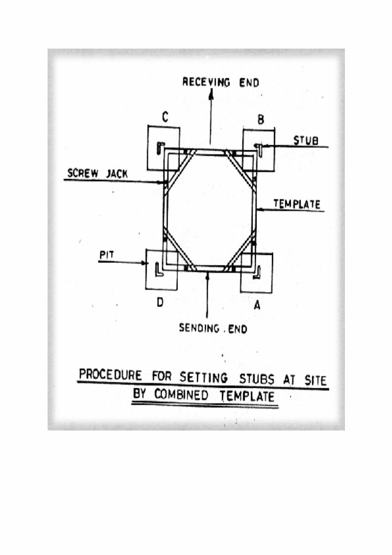
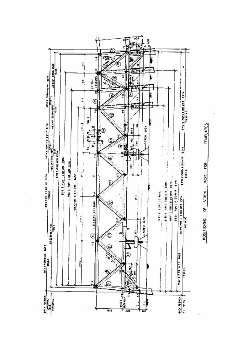
CHAPTER-4
Foundation Construction
___________________________________________________________________________
CHAPTERFOUR
___________________________________________________________________________
FOUNDATION CONSTRUCTION
Back to contents page
4.0 Concrete Type
Back to contents page
For reasons of economy and progress it is normal practice to use coarse and
fine aggregates available along with line route and/or nearest locations of the
route. As such, it is not practicable to design the concrete mix and use
controlled concrete. Moreover, since the quantity of concrete involved is rather
small, ordinary plain or reinforced cement concrete given in IS 456:1978 shall
be used in overhead line foundations.
4.1 Mixes
Back to contents page
For main foundation, M 150 or 1:2:4 (Volume) mix cement concrete generally
used. For lean concrete sub-bases or pads, M 100 or 1:3:6 mix cement
concrete may be used. The properties of concrete and mix proportions shall be
'in conformation to IS 456:1978.
It shall be permissible to proportionate the concrete as follows:
a) Prepare a wooden measuring box of 35 liters capacity (that is. equal to
1 bag or 50 kg of cement with inside dimensions of not exceeding
30 x 30 x 30 cm or alternatively 34 cm diameter and 39 cm height.
The mix quantities according to the measuring box shall be as follows:
S. No. Item M 150 M 100
1. Cement 1 bag 1 bag
2. Sand 2 boxes 3 boxes
3. Stone 4 boxes 6 boxes
4. Water 1 box less 1 boxes less
3 liters 1 liters
b) Measurement of water may be made with separate water-tight drums of
the above size or with 1-or 2-litre mugs.
Note: For concreting the bored foundations by displac-ing the drilling muds,
10 percent extra cement in the mix is required.
One bag of cement is taken to contain 50 kg or 35 liters of ordinary portland
cement.
4.2 Sizes of Aggregates
Back to contents page
The coarse aggregates (stone) to be used shall be single size aggregates of 40
mm nominal size for slab/pyamid concrete and 20 mm nominal size for
chimney concrete conforming to IS 383 : 1970. These sizes are applicable to
ordinary plain cement concrete for RCC, the aggregates shall preferably be of
20 mm nominal size. The fine aggregate (sand) shall be of Zone I Grade
conforming to IS:383 : 1970 which is the coarse variety with maximum
particle size of 4.75 mm. Zone II Grade of fine aggregates may also be used.
4.3 Gravel Sub-base
Back to contents page
In case the foundation happens to be over fine sand, 80 mm chick gravel sub-
base may be provided, if considered necessary, under the' foundation. The
maximum size of gravel or stone to be used shall be 80 mm.
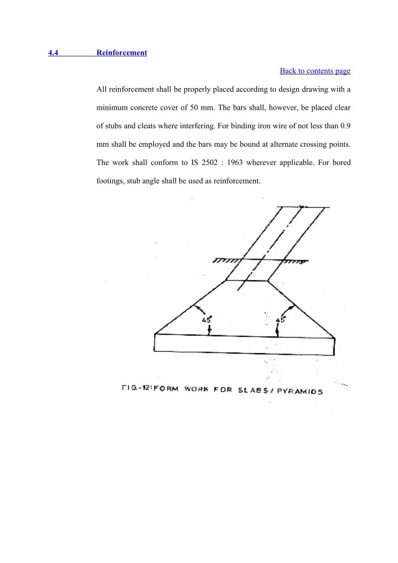
4.4 Reinforcement
Back to contents page
All reinforcement shall be properly placed according to design drawing with a
minimum concrete cover of 50 mm. The bars shall, however, be placed clear
of stubs and cleats where interfering. For binding iron wire of not less than 0.9
mm shall be employed and the bars may be bound at alternate crossing points.
The work shall conform to IS 2502 : 1963 wherever applicable. For bored
footings, stub angle shall be used as reinforcement.
In case the foundation having steel reinforcement in pyramid on base slab, at
least 50 mm Chick pad of lean concrete of 1: 3:6 nominal mix shall be
provided to avoid the possibility of reinforcement rod being exposed due to
unevenness of the bottom of the excavated pit.
4.5 Form Work
Back to contents page
4.5.1 General
The form work shall conform to the shape, lines and dimensions as shown on
the design drawings, and be so constructed as to be regid during the placing &
the compacting of concrete, and shall be sufficiently tight to prevent loss of
liquid from concrete. It shall be of light design & easily removable without
distortions and shall be of steel, hardwood or framed plywood. The inner
surface coming in contact with concrete shall be smooth and free form
projections. Window on one face shall be provided for pyramid forms to
facilitate concreting in the lower parts which shall be fixed after concrete in
the bottom part is placed. In bored footings form work may be needed only
towards the top for the portion above ground level.
The form work for slabs and pyramids shall be made symmetrical about the
base of the chimney to ensure interchangeable faces as illustrated in Fig. 12.
4.5.2 Clearing and Treatment of Forms
All rubbish, particularly chippings, shavings and sawdust and traces of
concrete, if any, shall be removed form the interior of the forms before the
concrete is placed. The surface in contact with the concrete shall be wetted and
sprayed with fine sand, or treated with an approved composition before use,
every time. Concreting to be done for cold weather shall be as per IS 7861(Part
2) : 1981
4.5.3 Stripping Time under fair weather conditions (generally where average daily
temperature is 20"C or above) , and where ordinary cement is used, forms may
be removed after 24 to 48 hours of the placing of concrete. In dull weather
such as in rainy periods or in very cold temperature, the forms shall be
removed after 48 hours of the placing of concrete.
4.6 'Mixing, Placing and Compacting of Concrete
Back to contents page
4.6.1 Mixing
Concrete shall preferably be mixed in a mechanical mixer, but hand mixing
shall be permissible. In case of emergency (when mechanical mixers are in
use) such as failure of the mixers, or where it is not practicable to haul the
mixers up to the location, and also for lean concrete sub-base, hand mixing
may be resorted to.
When hand mixing is adopted, it shall be carried out on water-tight platforms,
such as 1.8 mm galvanized iron plain sheets properly overlapped and placed
upon level ground. The coarse aggregates shall first be evenly spread out in
required quantity over the sheets. The fine aggregates shall be evenly spread
out over coarse aggregates. The aggregates shall then be thoroughly mixed
together and levelled. The required amount of cement shall be spread evenly
over the mixed aggregates and wet mixing shall start from one end with
required amount of water suing showels. The whole lot shall not be wetted,
instead mixing shall proceed progressively. If the aggregates are wet or
washed, cement shall not be spread out, but shall be put in progressively.
For mixing in the mechanical mixers, the same order of placing ingredients in
the drum shall be adopted, that is, coarse aggregates shall be put in first
followed by sand, cement and water.
Mixing shall be continued until there is a uniform distribution of material and
the mass is unform in colour and consistency but in no case shall mixing be
done for less than 2 minutes.
If the aggregates are wet, the amount of water shall be reduced suitably.
4.6.2 Transporting
Normally mixing shall be done right at the foundation. In places where it is not
possible, concrete may be mixed at the nearest convenient place. The concrete
shall be handled from the place of mixing to the place of final desposit as
rapidly as practicable by methods which shall prevent the segregation or loss
of any of the ingredients. If segregation does occur during transport the
concrete shall be remixed before being placed.
During hot or cold weather, concrete shall be transported in deep containers;
the deep containers, on account of their lower ratio of surface area to mass,
reduce the rate of loss of water by evaporation during hot weather and loss o'f
heat during cold weather.
4.6.3 Placing and Compacting
The concrete shall be placed and compacted before settling commences and
should not be subsequently disturbed. The placing should be such that no
segregation takes place.
Concrete shall be thoroughly compacted during the placing operation, and
thoroughly worked around reinforcement, around embedded fixtures and into
corners of form work by means of 16 mm diameter poking bars pointed at the
ends. The poking bars be worked 100 times in an area of 200 mm square for
300 mm depth. Over compaction causes the liquid to flow out upward causing
segregation and should be avoided.
If, after the form work has been struck, the concrete surface is found to have
defects, all the damaged surfaces shall be repaired with mortar application
composed of cement and sand in the same proportion as the cement and sand
in the concrete mix. Such repairs shall be carried out well before the
foundation pits are back filled.
Precautions to be taken on concrete work in extreme weather and under water,
as per the provisions of IS 4565:1978.
Field tests on workability of concrete and consistency may be carried out in the
form of slump test in accordance with IS 1199:1959.
4.7 Back Filling
Back to contents page
Following opening of form work and removal of shoring and strutting, if any,
back filling shall be started after repair, if any, to the foundation concrete.
Back filling shall normally be done -with the excavated soil, unless it consists
of large boulders / stones, in which case the boulders shall be broken to a
maximum size of 80 mm. The back filling materials should be clean and free
from organic or other foreign materials. The earth shall be deposited in
maximum 200 mm layers, levelled and wetted and tamped properly before
another layer is deposited. Care shall be taken that the back filling is started
from the foundation ends of the pits, towards the outer ends. After pits have
been back filled to full depth, the stub template may be removed.
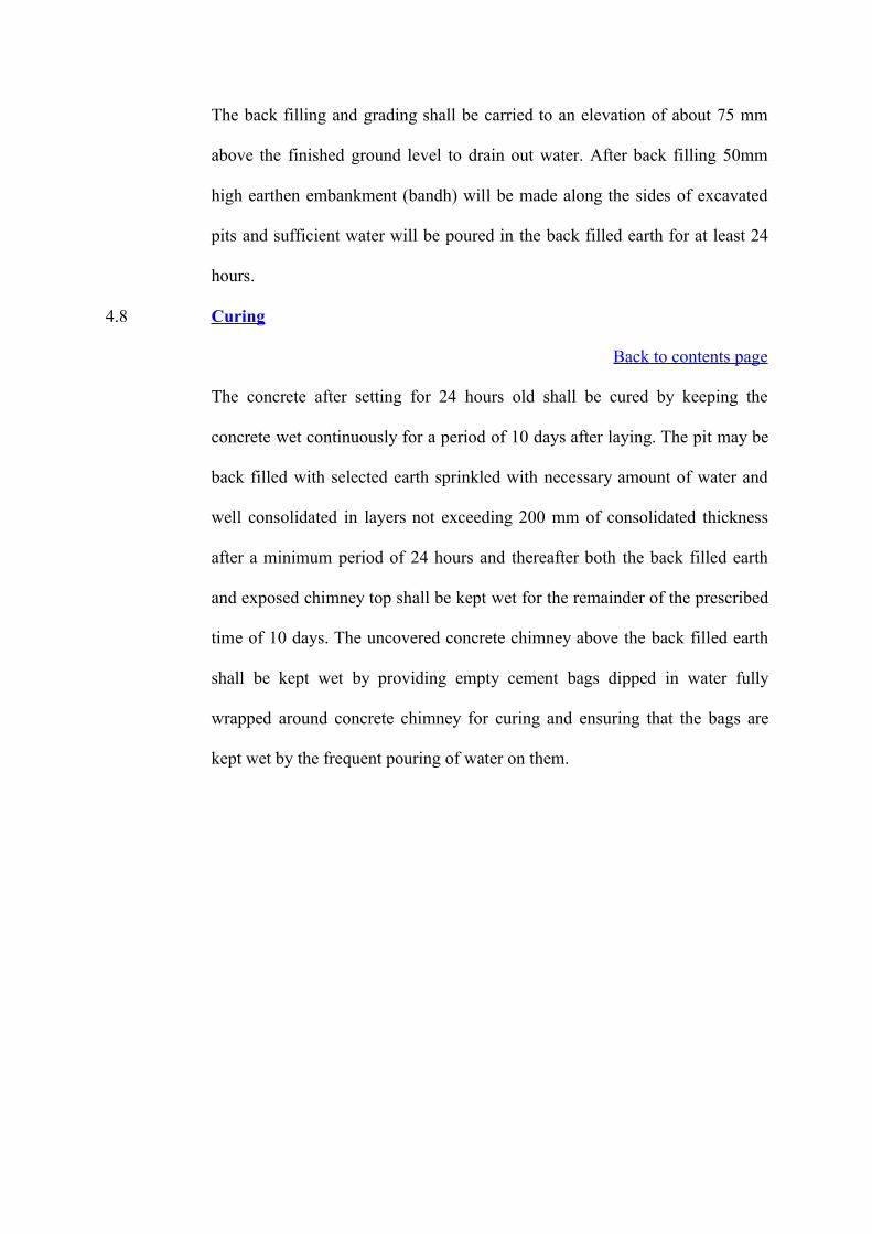
The back filling and grading shall be carried to an elevation of about 75 mm
above the finished ground level to drain out water. After back filling 50mm
high earthen embankment (bandh) will be made along the sides of excavated
pits and sufficient water will be poured in the back filled earth for at least 24
hours.
4.8 Curing
Back to contents page
The concrete after setting for 24 hours old shall be cured by keeping the
concrete wet continuously for a period of 10 days after laying. The pit may be
back filled with selected earth sprinkled with necessary amount of water and
well consolidated in layers not exceeding 200 mm of consolidated thickness
after a minimum period of 24 hours and thereafter both the back filled earth
and exposed chimney top shall be kept wet for the remainder of the prescribed
time of 10 days. The uncovered concrete chimney above the back filled earth
shall be kept wet by providing empty cement bags dipped in water fully
wrapped around concrete chimney for curing and ensuring that the bags are
kept wet by the frequent pouring of water on them.
CHAPTER-5
Protection of Foundation
___________________________________________________________________________
CHAPTERFIVE
___________________________________________________________________________
PROTECTION OF FOUNDATIONS
Back to contents page
5.0 Concrete Type
Back to contents page
5.1 Uplift Resistance
Back to contents page
The transmission line foundations are designed to withstand both down thrust
and uplift forces. The resistance of the soil in compression in reasonably well.
However, the resistance to uplift is uncertain and there are many theories
reported for uplift resistance in literature. These theories are generally based
on a slip surface rising vertically from the edge of the footing or a surface
rising at an angle of friction from the vertical, thus forming a frustum (Fig.13).
Under the vertical surface theory the shear resistance along the sides of the
plane or cylinder is calculated and added to the dead weight of the soil and
footing. Under the angle of friction theory, the dead weight within the frustum
is considered to provide resistance against uplift. Test results have shown that
neither of these methods provide reliable results. The cone method is usually
conservative at a shallow depth. This problem is solved by constructing
revetment or benching around the complete tower foundation or individual
tower leg.
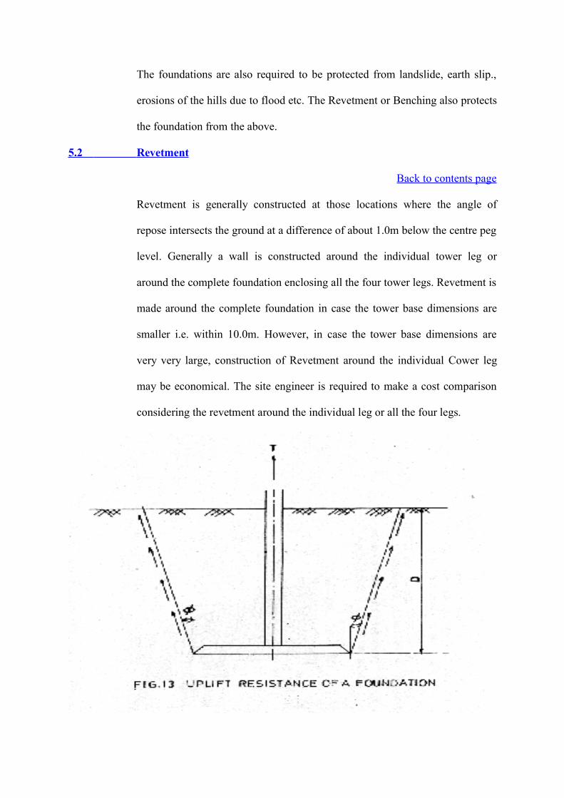
The foundations are also required to be protected from landslide, earth slip.,
erosions of the hills due to flood etc. The Revetment or Benching also protects
the foundation from the above.
5.2 Revetment
Back to contents page
Revetment is generally constructed at those locations where the angle of
repose intersects the ground at a difference of about 1.0m below the centre peg
level. Generally a wall is constructed around the individual tower leg or
around the complete foundation enclosing all the four tower legs. Revetment is
made around the complete foundation in case the tower base dimensions are
smaller i.e. within 10.0m. However, in case the tower base dimensions are
very very large, construction of Revetment around the individual Cower leg
may be economical. The site engineer is required to make a cost comparison
considering the revetment around the individual leg or all the four legs.

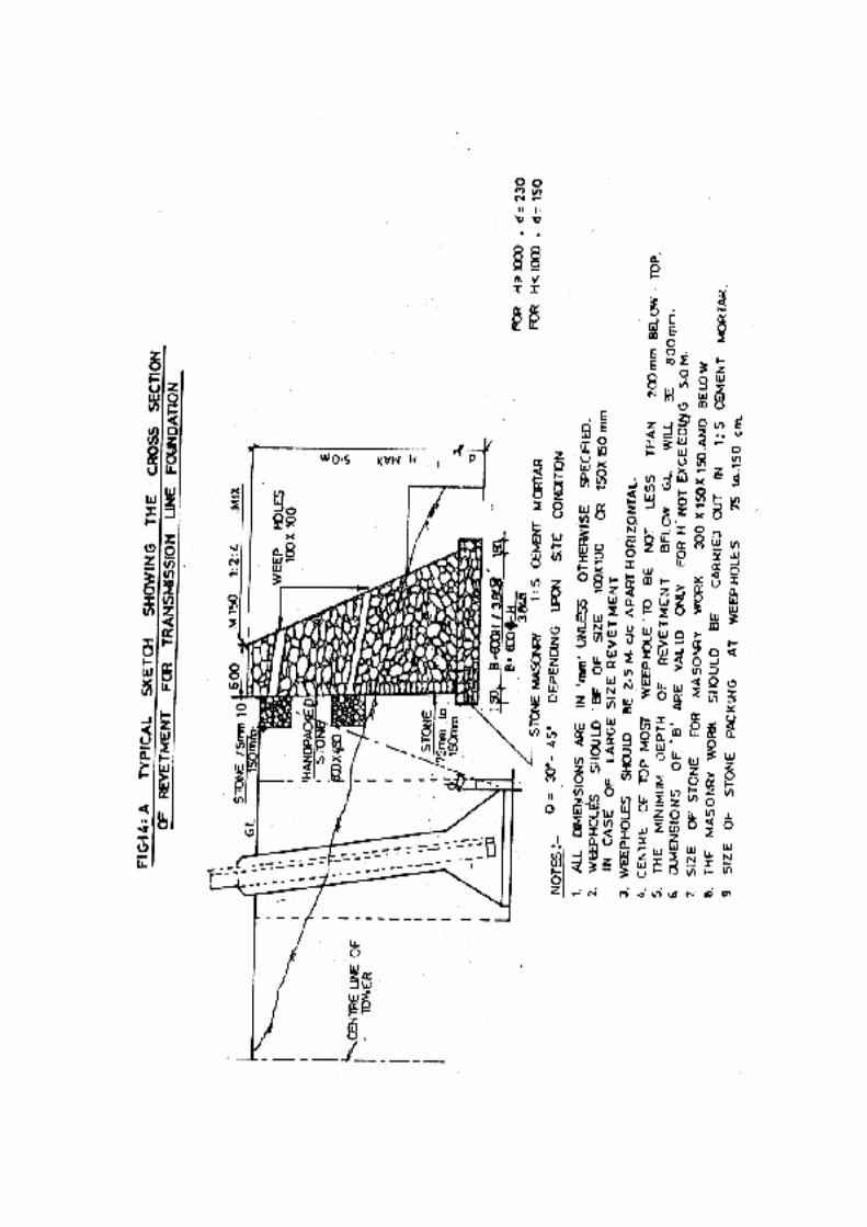
The Revetment wall can be constructed by random rubble masonry wall with
rectangular cross section having a width of 450mm and a staggered depth of
1 1/2 times the exposed portion of wall above ground level. A Random Rubble
masonry, wall of Trapezoidal cross section (Fig. 14) may be constructed for
the difference of elevation above 1m.
In case tower is located in hill slope i.e. where the difference in elevations is
very large. Revetments may not be economical. In such cases leg extensions of
structural steel can be designed for the standard length. No Revetment is to
made for the purpose of stub setting. Revetments should not be done for
levelling the-area under the tower base for the purpose of stub setting. The
payment for the levelling the area and Trench excavations along the sides as
well as diagonals of the tower legs is included in the unit rate of stub setting.
5.3 Benching
Back to contents page
When the line passes -through .the hilly/undulated terrain, levelling of the
ground may be required for casting of the tower foundation as to protect the
stub from corrosion. All such activities shall be termed as benching and shall
include the cutting of excess earth above the centre peg level and filling the
same in the area below the centre peg level.
It is preferable to do the benching work after construction of the Revetment
wall since the excavation will infringe with the filled soil of the benching work
and cause inconvenience for excavation.
5.4 Protection of Foundation against Chemical Water
Back to contents page
Whenever the chemicals are present in water in contact with steel or R.C.C.
member it will have a deteriorating effect on concrete as well as steel. To
prevent this, concrete incashing on the steel members to be done and
Bituminious paint to be provided over the concrete surface. The concrete
incasing to be done upto 200mm above the chemical water level. The bracing
members are to be enclosed accordingly. Minimum 50 mm clear cover to be
provided over the steel member.
5.5 Measurement of Volume for rivetment and benching
Back to contents page
5.5.1 General
There are three methods generally adopted for measuring the volume. They are
:
(i) From cross-sections
(ii) From spot levels
(iii) From contours
The first two methods are commonly used for the calculation of each work
while the third method is generally adopted for the calculation of of depressed
area.
5.5.2 Measurement from Cross-Sections
This is the most widely used method. The total volume is divided into a series
of solids by the planes of cross-sections. The fundamental solids on which
measurement is based are the prism, wedge and prismoid. The spacing of the
sections depends upon the character of the ground and the accuracy required in
the measurement. The area of the cross-section taken along the line are first
calculated by standard formulae developed below, and the volumes of the
prismoids between successive cross-sections are then calculated by either
trapezoidal formula or by prismodial formula.
The various cross-sections may be classified as
(i) Level section, (Figs. 15 and 16)
(ii) Two-level section, (Fig. 17)
(iii) Side hill two-level section, (Fig. 18)
(iv) Three-level section (Fig. 19) and
(v) Multi-level section (Fig. 20).
General notations : Let
b = the constant formation (or sub-grade) width
h = the depth of cutting on centre line
w1 and w2 = the side widths, or half breadths, i.e., the horizontal distances
from the centre to the intersection of the side slopes with original ground level.
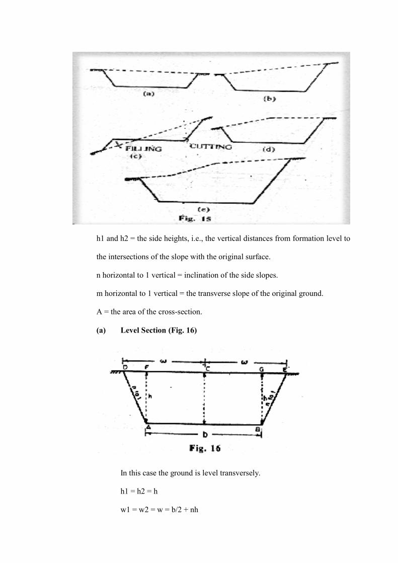
h1 and h2 = the side heights, i.e., the vertical distances from formation level to
the intersections of the slope with the original surface.
n horizontal to 1 vertical = inclination of the side slopes.
m horizontal to 1 vertical = the transverse slope of the original ground.
A = the area of the cross-section.
(a) Level Section (Fig. 16)
In this case the ground is level transversely.
h1 = h2 = h
w1 = w2 = w = b/2 + nh
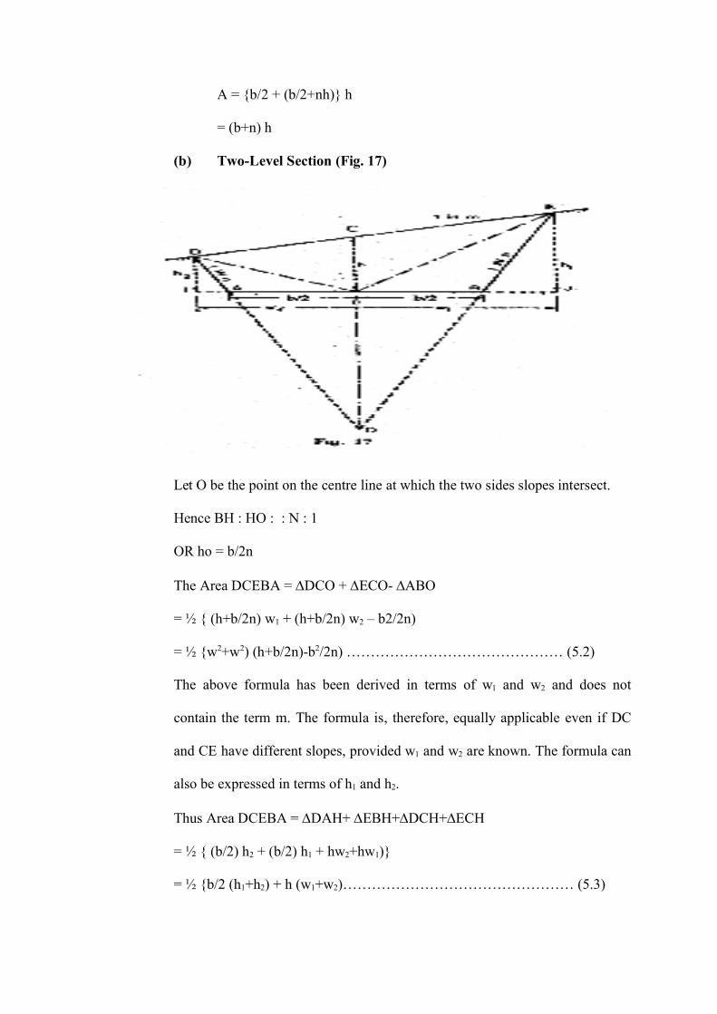
A = {b/2 + (b/2+nh)} h
= (b+n) h
(b) Two-Level Section (Fig. 17)
Let O be the point on the centre line at which the two sides slopes intersect.
Hence BH : HO : : N : 1
OR ho = b/2n
The Area DCEBA = DCO + ECO- ABO
= ½ { (h+b/2n) w1 + (h+b/2n) w2 – b2/2n)
= ½ {w2+w2) (h+b/2n)-b2/2n) ……………………………………… (5.2)
The above formula has been derived in terms of w1 and w2 and does not
contain the term m. The formula is, therefore, equally applicable even if DC
and CE have different slopes, provided w1 and w2 are known. The formula can
also be expressed in terms of h1 and h2.
Thus Area DCEBA = DAH+ EBH+DCH+ECH
= ½ { (b/2) h2 + (b/2) h1 + hw2+hw1)}
= ½ {b/2 (h1+h2) + h (w1+w2)………………………………………… (5.3)
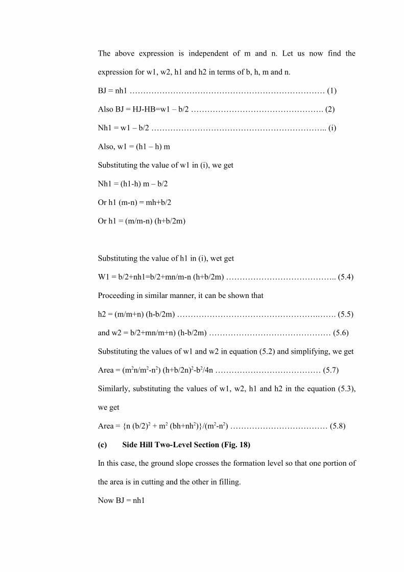
The above expression is independent of m and n. Let us now find the
expression for w1, w2, h1 and h2 in terms of b, h, m and n.
BJ = nh1 ……………………………………………………………… (1)
Also BJ = HJ-HB=w1 – b/2 …………………………………………. (2)
Nh1 = w1 – b/2 ……………………………………………………….. (i)
Also, w1 = (h1 – h) m
Substituting the value of w1 in (i), we get
Nh1 = (h1-h) m – b/2
Or h1 (m-n) = mh+b/2
Or h1 = (m/m-n) (h+b/2m)
Substituting the value of h1 in (i), wet get
W1 = b/2+nh1=b/2+mn/m-n (h+b/2m) ………………………………….. (5.4)
Proceeding in similar manner, it can be shown that
h2 = (m/m+n) (h-b/2m) …………………………………………….……. (5.5)
and w2 = b/2+mn/m+n) (h-b/2m) ……………………………………… (5.6)
Substituting the values of w1 and w2 in equation (5.2) and simplifying, we get
Area = (m2n/m2-n2) (h+b/2n)2-b2/4n ………………………………… (5.7)
Similarly, substituting the values of w1, w2, h1 and h2 in the equation (5.3),
we get
Area = {n (b/2)2 + m2 (bh+nh2)}/(m2-n2) ……………………………… (5.8)
(c) Side Hill Two-Level Section (Fig. 18)
In this case, the ground slope crosses the formation level so that one portion of
the area is in cutting and the other in filling.
Now BJ = nh1
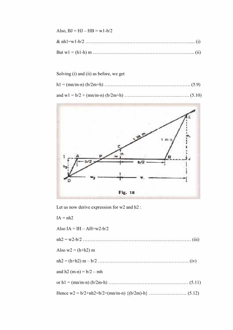
Also, BJ = HJ – HB = w1-b/2
& nh1=w1-b/2 …………………………………………………………..... (i)
But w1 = (h1-h) m ……………………………………………………….. (ii)
Solving (i) and (ii) as before, we get
h1 = (mn/m-n) (b/2m+h) ………………………………………………. (5.9)
and w1 = b/2 + (mn/m-n) (b/2m+h) ……………………………..……. (5.10)
Let us now derive expression for w2 and h2 :
IA = nh2
Also IA = IH – AH=w2-b/2
nh2 = w2-b/2 …………………………………………………………… (iii)
Also w2 = (h+h2) m
nh2 = (h+h2) m – b/2 …………………………………………………. (iv)
and h2 (m-n) = b/2 – mh
or h1 = (mn/m-n) (b/2m-h) …………………………………………… (5.11)
Hence w2 = b/2+nh2=b/2+(mn/m-n) {(b/2m)-h} …………………… (5.12)
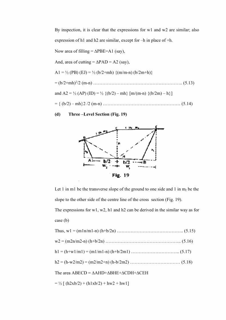
By inspection, it is clear that the expressions for w1 and w2 are similar; also
expression of h1 and h2 are similar, except for –h in place of +h.
Now area of filling = PBE=A1 (say),
And, area of cutting = PAD = A2 (say),
A1 = ½ (PB) (EJ) = ½ (b/2+mh) {(m/m-n) (b/2m+h)}
= (b/2+mh)2/2 (m-n) ………………………………………………….. (5.13)
and A2 = ½ (AP) (ID) = ½ {(b/2) – mh} [m/(m-n) {(b/2m) – h}]
= { (b/2) – mh}2 /2 (m-n) …………………………………………… (5.14)
(d) Three –Level Section (Fig. 19)
Let 1 in m1 be the transverse slope of the ground to one side and 1 in m2 be the
slope to the other side of the centre line of the cross section (Fig. 19).
The expressions for w1, w2, h1 and h2 can be derived in the similar way as for
case (b)
Thus, w1 = (m1n/m1-n) (h+b/2n) …………………………………….. (5.15)
w2 = (m2n/m2-n) (h+b/2n) ………………………………………….. (5.16)
h1 = (h+w1/m1) = (m1/m1-n) (h+b/2m1) ………………………….. (5.17)
h2 = (h-w2/m2) = (m2/m2+n) (h-b/2m2) …………………………… (5.18)
The area ABECD = AHD+BHE+CDH+CEH
= ½ [ (h2xb/2) + (h1xb/2) + hw2 + hw1]
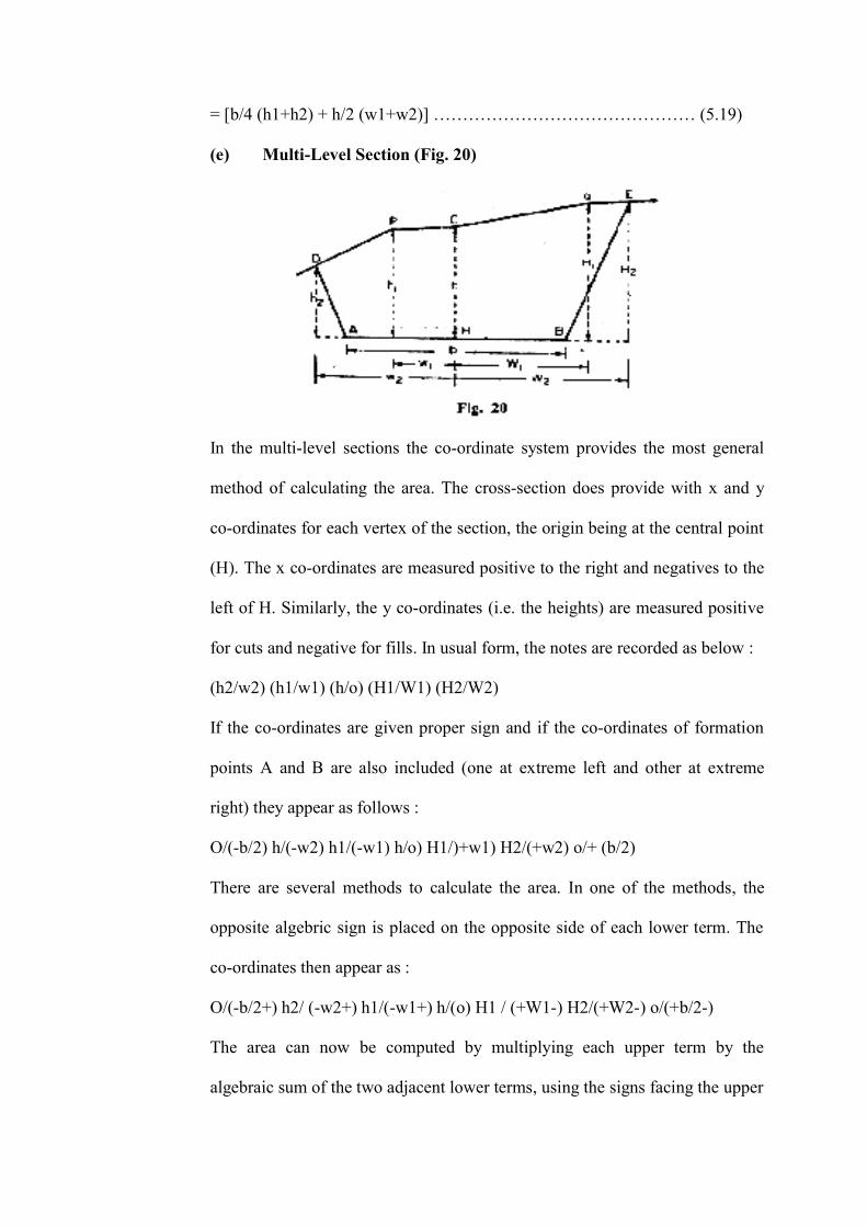
= [b/4 (h1+h2) + h/2 (w1+w2)] ……………………………………… (5.19)
(e) Multi-Level Section (Fig. 20)
In the multi-level sections the co-ordinate system provides the most general
method of calculating the area. The cross-section does provide with x and y
co-ordinates for each vertex of the section, the origin being at the central point
(H). The x co-ordinates are measured positive to the right and negatives to the
left of H. Similarly, the y co-ordinates (i.e. the heights) are measured positive
for cuts and negative for fills. In usual form, the notes are recorded as below :
(h2/w2) (h1/w1) (h/o) (H1/W1) (H2/W2)
If the co-ordinates are given proper sign and if the co-ordinates of formation
points A and B are also included (one at extreme left and other at extreme
right) they appear as follows :
O/(-b/2) h/(-w2) h1/(-w1) h/o) H1/)+w1) H2/(+w2) o/+ (b/2)
There are several methods to calculate the area. In one of the methods, the
opposite algebric sign is placed on the opposite side of each lower term. The
co-ordinates then appear as :
O/(-b/2+) h2/ (-w2+) h1/(-w1+) h/(o) H1 / (+W1-) H2/(+W2-) o/(+b/2-)
The area can now be computed by multiplying each upper term by the
algebraic sum of the two adjacent lower terms, using the signs facing the upper
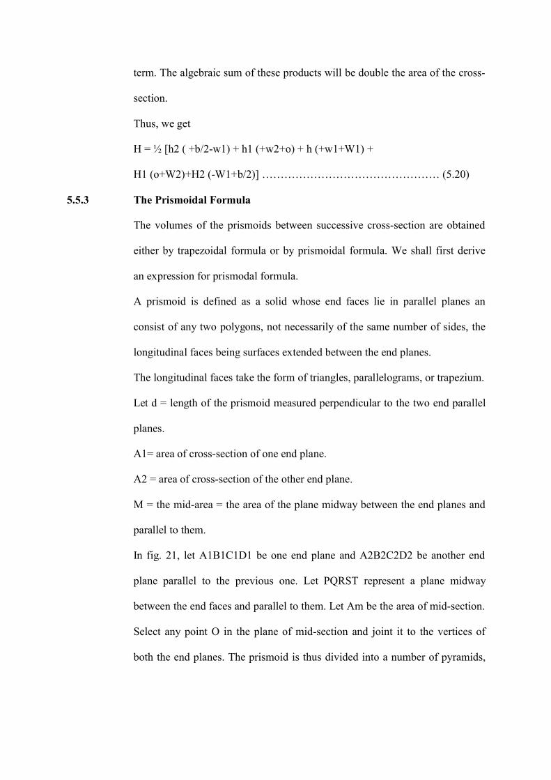
term. The algebraic sum of these products will be double the area of the cross-
section.
Thus, we get
H = ½ [h2 ( +b/2-w1) + h1 (+w2+o) + h (+w1+W1) +
H1 (o+W2)+H2 (-W1+b/2)] ………………………………………… (5.20)
5.5.3 The Prismoidal Formula
The volumes of the prismoids between successive cross-section are obtained
either by trapezoidal formula or by prismoidal formula. We shall first derive
an expression for prismodal formula.
A prismoid is defined as a solid whose end faces lie in parallel planes an
consist of any two polygons, not necessarily of the same number of sides, the
longitudinal faces being surfaces extended between the end planes.
The longitudinal faces take the form of triangles, parallelograms, or trapezium.
Let d = length of the prismoid measured perpendicular to the two end parallel
planes.
A1= area of cross-section of one end plane.
A2 = area of cross-section of the other end plane.
M = the mid-area = the area of the plane midway between the end planes and
parallel to them.
In fig. 21, let A1B1C1D1 be one end plane and A2B2C2D2 be another end
plane parallel to the previous one. Let PQRST represent a plane midway
between the end faces and parallel to them. Let Am be the area of mid-section.
Select any point O in the plane of mid-section and joint it to the vertices of
both the end planes. The prismoid is thus divided into a number of pyramids,
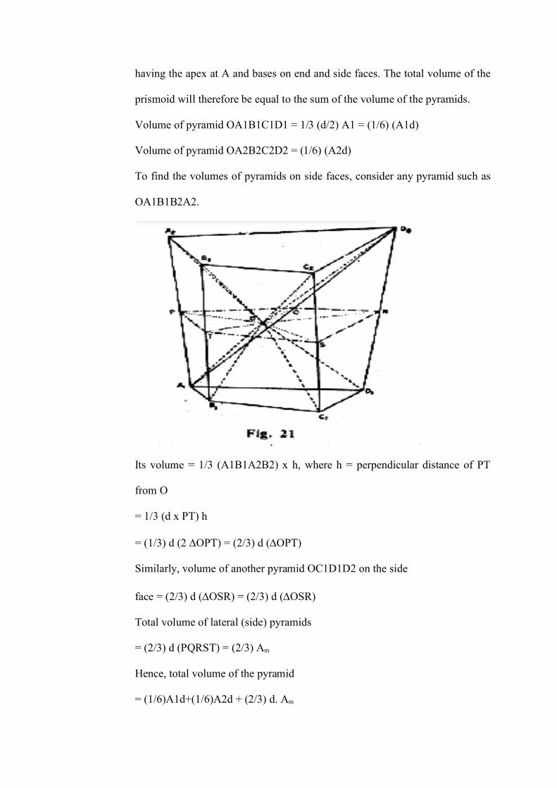
having the apex at A and bases on end and side faces. The total volume of the
prismoid will therefore be equal to the sum of the volume of the pyramids.
Volume of pyramid OA1B1C1D1 = 1/3 (d/2) A1 = (1/6) (A1d)
Volume of pyramid OA2B2C2D2 = (1/6) (A2d)
To find the volumes of pyramids on side faces, consider any pyramid such as
OA1B1B2A2.
Its volume = 1/3 (A1B1A2B2) x h, where h = perpendicular distance of PT
from O
= 1/3 (d x PT) h
= (1/3) d (2 OPT) = (2/3) d (OPT)
Similarly, volume of another pyramid OC1D1D2 on the side
face = (2/3) d (OSR) = (2/3) d (OSR)
Total volume of lateral (side) pyramids
= (2/3) d (PQRST) = (2/3) Am
Hence, total volume of the pyramid
= (1/6)A1d+(1/6)A2d + (2/3) d. Am
V = d/6 (A1+A2+4Am) …………………………………………..……. (5.21)
Let us now calculate the volume of earth work between a number of sections
having area A1, A2, A3 ………, An spaced at constant distance d apart.
Considering the prismoid between first three sections, its volume will be, from
equation (5.21).
= (2d/6) (A1+4A2+A3), 2d being the length of the prismoid.
Similarly, volume of the second prismoid of length 2d will be
= (2d/6) (A2+4A4+A5),
and volume of last prismoid of length 2d will be
= 2d/6 (An-2+4An-1+An)
Summing up, we get the total volume,
V= (d/3) [A1+4A2+2A3+4A4+ … + 2An-2+4An-1+An] …………… (5.22)
or V = (d/3) [(A1+An) + 4 (A2+A4+An-1)+2 (A3+A5+An-2)]
This is also known as Simpson’s rule for volumes. Here also, it is necessary to
have an odd number of cross-sections. If there are even number of sections, the
end strip must be treated separately, and the volume between the remaining
sections may be calculated by prismodial formula.
5.5.4 The Trapezoidal Formula (Average end area method)
This method is based on the assumption that the mid area is the mean of the
end areas. In that case, the volume of the prismoid of Fig. 21 is given by
V = (d/2) (A1+A2)
This is true only if the prismoid is composed of prisms and wedges only and
not of pyramids. The mid area of pyramid is half the average area of the ends;
hence the volume of the prismoid (having pyramids also) is over estimated.
However, the method of end area may not be accepted with sufficient accuracy
since the actual earth solid may not be exactly a prismoid. In some cases, the
volume is calculated and then a correction is applied, the correction being
equal to the difference between the volume as calculated and that which could
be obtained by the use of the prismoid formula. The correction is known as the
prismoidal correction.
Let us now calculate the volume of earth work between a number of sections
having areas A1, A2, ……… An spaced at a constant distance d.
Volume between first two sections = (d/2) (A1+A2)
Volume between next two sections = (d/2) (A3+A4)
Volume between last two sections = (d/2) (An-1+An)
Total Volume = V=d {(A1+A2)/2+A2+A3+An-1} …………………… (5.23)
5.5.5 The Prismoidal Correction (Cp)
As stated earlier, the prismoidal correction is equal to the difference between
the volumes as calculated by the end-area formula and the prismoidal formula.
The correction is always substractive, i.e. it should be substracted from the
volume calculated by the end area formula.
Let us calculate the prismoidal correction for the case when the end sections
are level sections. Let A, w1, w2, h1, h2 etc., refer to the cross-sections at one
end and A, w1, w2, h1, h2, etc., to the cross section at the other end.
Now A=h (b+nh)
And A = h (b+nh)
Volume by end area rule is given by
V = (d/2) [h (b+nh) + h (b+nh)]
= d [bh/2+bh/2+nh2/2+nh2/2] ……………………………………………. (i)
Again, the mid-area centre height = (h+h’)/2
Mid-area = {(h+h’)/2} [{b+n(h+h’)/2}]
Volume by prismoidal formula given by
V = d/6 [h(b+nh)+h’ (b+nh’)+4 {(h+h’)/2} x {(b+n(h+h’)/2}]
V=d/6 [3bh+3bh’+2+nh2+2nh’2+2nhh’]
=[bh/2+bh’/2+bh’/2+nh2/3+nh’2/3+nhh’/3] …………………………… (ii)
Substracting (ii) from (i), we get the prismoidal correction,
Cp = (dn/6) (h-h’)2 ………………………………………………… (5.24)
Similarly, the prismoidal correction for other sections can also be drived. The
standard expression for C2 are given below.
For two level section :
C2 = d/6n (w1-w’1) (w2-w’2) …………………………………….. (5.25)
For side hill two-level section ;
Cp (cutting) = (d/12n) (w1-w’1) {(b/2+mh)-(b/2+m’h’)} ……….. (5.26)
Cp (filling) = (d/12n) (w2-w’2) {(d/2-mh) – (d/2-m’h’) …………. (5.27)
For three-level section :
Cp = (d/12) (h-h’) {(w1+w2) – (w1’+w2’) …………………….. (5.28)
5.5.6 The Curvature Correction
The prismoidal and the trapezoidal formulae were derived on the assumption
that the end sections are in parallel planes. When the centre line of cutting or
an embankment is curved in plane, it is common practice to calculate the
volume as if the end sections were in parallel planes, and then apply the
correction for curvature. The standard expression for various sections are
given below. In some cases, the correction for curvature is applied to the areas
of cross-sections thus getting equivalent areas and then to use the prismoidal
formula.
(i) Level section : No correction is necessary since the area is symmetrical
about the centre line.
(ii) Two-level section and three-level section ;
Cc = (d/6R) (w12-W22) (h+b/2n) ………………………..…… (5.29)
Where R is the radius of the curve.
(iii) For a two-level section, the curvature correction to the area
Ae/A per unit length ………………………………………… (5.30)
Where e= the eccentricity, i.e., horizontal distance from the centre line to the
centroid of the area = w1w2 (w1+w2)/3An …………………………. (5.31)
The correction is positive if the centroid and the centre of the curvature are to
the opposite side of the centre line while it is negative if the centroid and the
centre of the curvature are to the same side of the centre line.
(iv) For side hill two-level section :
Correction to area = Ae/R per unit length ……………………. (5.32)
Where e = (1/3) (w1+b/2-nh) for the larger area …………….. (5.33)
And e = (1/3) (w2+b/2nh) for the smaller area ……………… (5.34)
5.5.7 Volume from Spot Levels
In this method, the field work consists in dividing the area into a number of
squares, rectangles or triangles and measuring the levels of their corners before
and after the construction. Thus, the depth of excavation or height of filling at
every corner is known. Let us assume that the four corners of any one square
of rectangle are at different elevations but lie in the same inclined plane.
Assume that it is desired to grade down to a level surface a certain distance
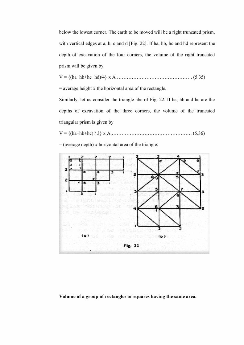
below the lowest corner. The earth to be moved will be a right truncated prism,
with vertical edges at a, b, c and d [Fig. 22]. If ha, hb, hc and hd represent the
depth of excavation of the four corners, the volume of the right truncated
prism will be given by
V = {(ha+hb+hc+hd)/4} x A ………………………………………. (5.35)
= average height x the horizontal area of the rectangle.
Similarly, let us consider the triangle abc of Fig. 22. If ha, hb and hc are the
depths of excavation of the three corners, the volume of the truncated
triangular prism is given by
V = {(ha+hb+hc) / 3} x A …………………………………………. (5.36)
= (average depth) x horizontal area of the triangle.
Volume of a group of rectangles or squares having the same area.
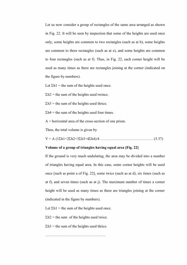
Let us now consider a group of rectangles of the same area arranged as shown
in Fig. 22. It will be seen by inspection that some of the heights are used once
only, some heights are common to two rectangles (such as at b), some heights
are common to three rectangles (such as at e), and some heights are common
to four rectangles (such as at f). Thus, in Fig. 22, each corner height will be
used as many times as there are rectangles joining at the corner (indicated on
the figure by numbers).
Let h1 = the sum of the heights used once.
h2 = the sum of the heights used twince.
h3 = the sum of the heights used thrice.
h4 = the sum of the heights used four times.
A = horizontal area of the cross-section of one prism.
Then, the total volume is given by
V = A (1h1+2h2+3h3+4h4)/4 …………………………………… (5.37)
Volume of a group of triangles having equal area [Fig. 22]
If the ground is very much undulating, the area may be divided into a number
of triangles having equal area. In this case, some corner heights will be used
once [such as point a of Fig. 22], some twice (such as at d), six times (such as
at f), and seven times (such as at j). The maximum number of times a corner
height will be used as many times as there are triangles joining at the corner
(indicated in the figure by numbers).
Let h1 = the sum of the heights used once.
h2 = the sum of the heights used twice.
h3 = the sum of the heights used thrice.
…………………………………………
…………………………………………
h8 = the sum of height used eight times.
A = area of each triangle.
The total volume of the group is given by
V = A/3 (1h1+2h2+3h3+4h4+5h5+6h6+7h7+8h8) ……….. (5.38)
5.5.8 Volume from Contour Plan
The amount of earth work or volume can be calculated by the contour plan
area. There are four distinct methods, depending upon the type of the work.
a) By Cross-Sections
It was indicated, that with the help of the contour plan, cross-section of
the existing ground surface can be drawn. On the same cross-section,
the grade line of the proposed work can be drawn and the area of the
section can be estimated either by oridinary methods or with the hel of
a planimeter.
Thus, in Fig. 23, the irregular line represents the origin ground while
the straight line ab is obtained after grading. The area of cut and of fill
can be found from the cross-section. The volumes of earth work
between adjacent cross-sections may be calculated by the use of
average and areas.
(b) By Equal Depth Contours
In this method, the contours of the finished or graded surface are drawn
on the contour map, at the same interval as that of the contours. At
every point, where the contours of the finished surface intersect a
contour of the existing surface the cut or fill can be found by simply
subtracting the difference in elevation between the two contours. By
joining the points of equal cut or fill, a set of lines is obtained
(represented by thick lines in Fig. 24). These lines are the horizontal
projections of lines cut from the existing surface by planes parallel to
the finished surface. The irregular area bounded by each of these lines
can be determined by the use of the planimeter. The volume between
any two successive area is determined by multiplying the average of
the two areas by the depth between them, or by prismoidal formula.
The sum of the volume of all the layers is the total volume required.
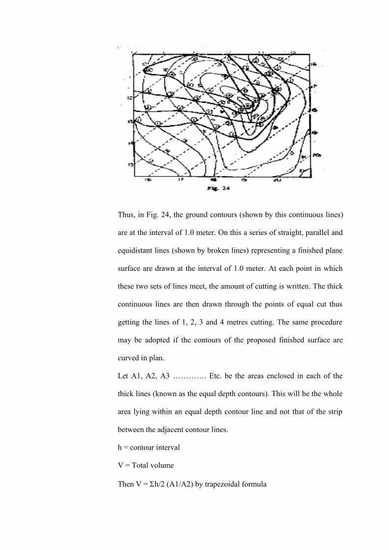
Thus, in Fig. 24, the ground contours (shown by this continuous lines)
are at the interval of 1.0 meter. On this a series of straight, parallel and
equidistant lines (shown by broken lines) representing a finished plane
surface are drawn at the interval of 1.0 meter. At each point in which
these two sets of lines meet, the amount of cutting is written. The thick
continuous lines are then drawn through the points of equal cut thus
getting the lines of 1, 2, 3 and 4 metres cutting. The same procedure
may be adopted if the contours of the proposed finished surface are
curved in plan.
Let A1, A2, A3 …………. Etc. be the areas enclosed in each of the
thick lines (known as the equal depth contours). This will be the whole
area lying within an equal depth contour line and not that of the strip
between the adjacent contour lines.
h = contour interval
V = Total volume
Then V = h/2 (A1/A2) by trapezoidal formula
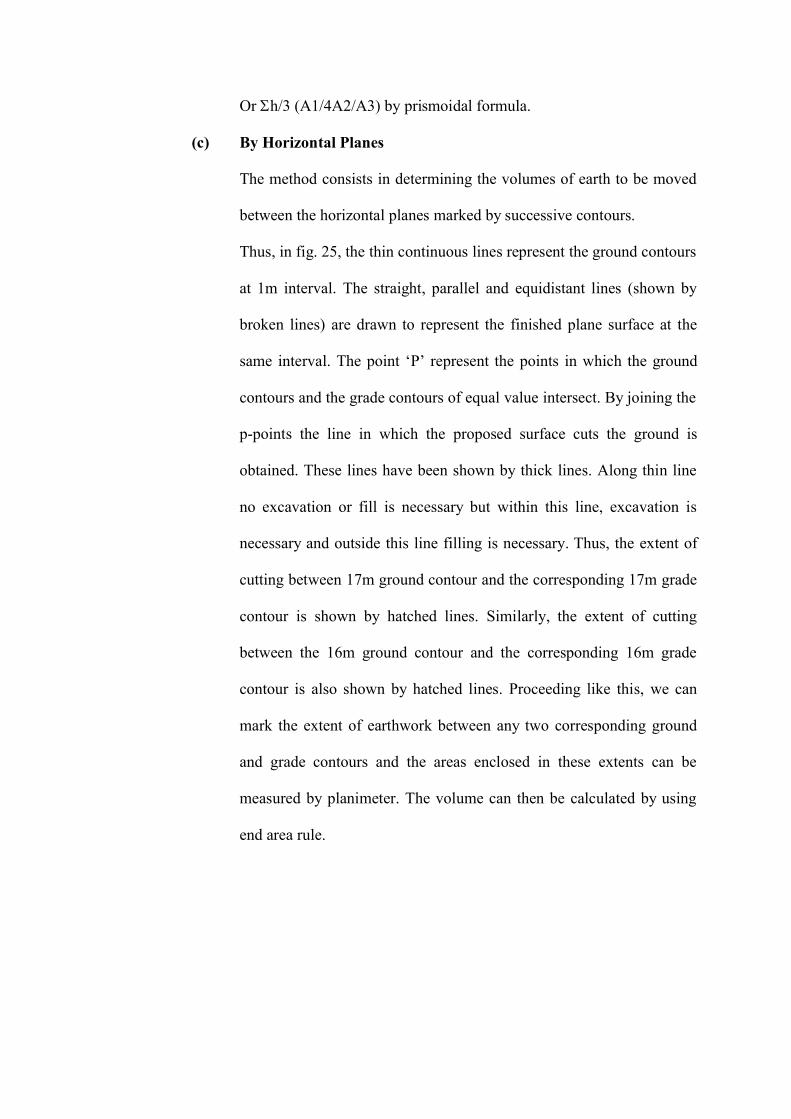
Or h/3 (A1/4A2/A3) by prismoidal formula.
(c) By Horizontal Planes
The method consists in determining the volumes of earth to be moved
between the horizontal planes marked by successive contours.
Thus, in fig. 25, the thin continuous lines represent the ground contours
at 1m interval. The straight, parallel and equidistant lines (shown by
broken lines) are drawn to represent the finished plane surface at the
same interval. The point ‘P’ represent the points in which the ground
contours and the grade contours of equal value intersect. By joining the
p-points the line in which the proposed surface cuts the ground is
obtained. These lines have been shown by thick lines. Along thin line
no excavation or fill is necessary but within this line, excavation is
necessary and outside this line filling is necessary. Thus, the extent of
cutting between 17m ground contour and the corresponding 17m grade
contour is shown by hatched lines. Similarly, the extent of cutting
between the 16m ground contour and the corresponding 16m grade
contour is also shown by hatched lines. Proceeding like this, we can
mark the extent of earthwork between any two corresponding ground
and grade contours and the areas enclosed in these extents can be
measured by planimeter. The volume can then be calculated by using
end area rule.

CHAPTER-6
Concrete Technology
___________________________________________________________________________
CHAPTERSIX
___________________________________________________________________________
CONCRETE TECHNOLOGY
Back to contents page
6.1 Introduction
Back to contents page
Cement concrete is the most widely used structural material in the world for
civil engineering projects. Its versatility, economy, adaptability, and
worldwide availability, and especially its low maintenance requirements, make
it very useful. It consists of cement, water, and aggregate which have been
mixed together, placed, consolidated, and allowed to solidify and harden. The
cement and water form a paste, which acts as the glue, or binder. When fine
aggregate is added the resulting mixture is termed mortar. Then when coarse
aggregate is included concrete is produced. Normal concrete consists of about
three-fourths aggregate and one-fourth paste, by volume. The paste usually
consists of water-cement ratios between 0.4 and 0.7 by weight. Admixtures are
sometimes added for specific purposes, such as to entrain numerous
microscopic air bubbles, impart colour, retard the initial set of the concrete,
waterproof the concrete, etc. The operations involved in the production of
concrete will vary with the type of end use for the concrete, but, in general, the
operations,include the following (Fig.26) :
a) Batching the materials
b) Mixing
c) Transporting
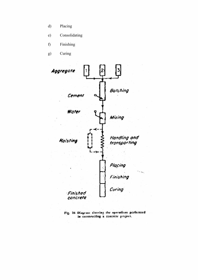
d) Placing
e) Consolidating
f) Finishing
g) Curing
6.2 Proportioning Concrete Mixtures
Back to contents page
For successful concrete utilization, the mixture must be properly proportioned.
First, although it takes water to initiate the hydraulic reaction, the higher the
water-cement ratio, the lower the resulting strength and durabilicy. Second,
the more water that is used the higher will be the slump. Third, the more
aggregate that is used, the lower the cost of the concrete. Fourth, the larger the
maximum size of coarse aggregate, the less the amount of cement paste that
will be needed to coat all the particles and provide necessary workability.
Fifth, the more that concrete is consolidated, the better it becomes. Sixth, The
use of properly entrained air enhances almost all concrete properties with little,
or no, decrease in strength if the mix proportions are adjusted for the air. And
seventh, the surface abrasion resistance of the concrete is almost entirely a
function of the properties of the fine aggregate.
6.3 Fresh Concrete
Back to contents page
To the designer, fresh' concrete is of little importance. To the constructor,
fresh concrete is all-important, because it is the fresh concrete that must be
mixed, transported, placed, consolidated, finished, and cured. To satisfy both
the designer and the constructor, the concrete should:
a) Be easily mixed and transported.
b) Be uniform throughout, both within a given batch and between batches.
c) Be of proper workability so that it can be consolidated, will completely
fill the forms, will not segregate, and will finish properly.
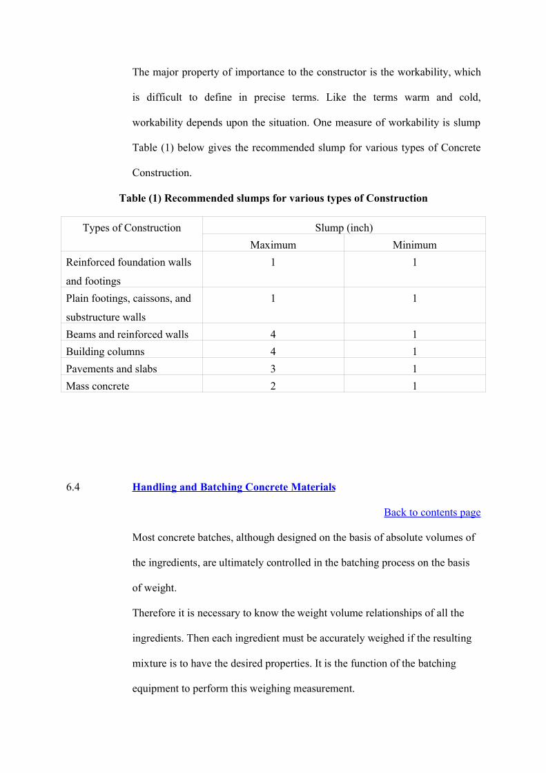
The major property of importance to the constructor is the workability, which
is difficult to define in precise terms. Like the terms warm and cold,
workability depends upon the situation. One measure of workability is slump
Table (1) below gives the recommended slump for various types of Concrete
Construction.
Table (1) Recommended slumps for various types of Construction
Types of Construction Slump (inch)Maximum Minimum
Reinforced foundation walls
and footings
1 1
Plain footings, caissons, and
substructure walls
1 1
Beams and reinforced walls 4 1Building columns 4 1Pavements and slabs 3 1Mass concrete 2 1
6.4 Handling and Batching Concrete Materials
Back to contents page
Most concrete batches, although designed on the basis of absolute volumes of
the ingredients, are ultimately controlled in the batching process on the basis
of weight.
Therefore it is necessary to know the weight volume relationships of all the
ingredients. Then each ingredient must be accurately weighed if the resulting
mixture is to have the desired properties. It is the function of the batching
equipment to perform this weighing measurement.
(i) Handling cement : Cement may be supplied to the project in paper
bags, each containing 1 Cu ft. loose measure and weighing 94 lb net.
However, for most large projects, the cement is supplied in bulk
quantities from cement is supplied in bulk quantities from cement
transport trucks, each holding 25 tons or more, or from railroad cars.
Bag cement must be stored in a dry place on pallets and should be left
in the original bags until used for concrete. If the batching of concrete
requires one or more whole bags of cement, the use of bag cement
simplifies the batching operation.
(ii) Batching and concrete : Usually, concrete specifications require the
concrete to be batched with aggregate having at least two size ranges
(coarse and fine) and up to six ranges. (Fig. 27) illustrates the proper
and improper methods of batching. Aggregate from each size range
must be accurately measured. The aggregate, water, cement, and
admixtures (if used) are introduced into a concrete mixer and mixed for
a suitable period of time until all the ingredients are adequately
blended together.
6.5 Batch plants and mixers
Back to contents page
There are two types of concrete-mixing operations in use, job-batched concrete
and central-batched concrete. Today, unless/the project is in a remote location
or is relatively large, more and more of the concrete is batched in a central
batch plant and transported to the job site in ready-mixed concrete trucks. Fig.
28 shows a portable concrete batch plant, and Fig. 29 shows, a large central
batch plant of the type in general use. A concrete batch required four different
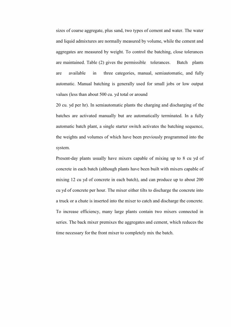
sizes of coarse aggregate, plus sand, two types of cement and water. The water
and liquid admixtures are normally measured by volume, while the cement and
aggregates are measured by weight. To control the batching, close tolerances
are maintained. Table (2) gives the permissible tolerances. Batch plants
are available in three categories, manual, semiautomatic, and fully
automatic. Manual batching is generally used for small jobs or low output
values (less than about 500 cu. yd total or around
20 cu. yd per hr). In semiautomatic plants the charging and discharging of the
batches are activated manually but are automatically terminated. In a fully
automatic batch plant, a single starter switch activates the batching sequence,
the weights and volumes of which have been previously programmed into the
system.
Present-day plants usually have mixers capable of mixing up to 8 cu yd of
concrete in each batch (although plants have been built with mixers capable of
mixing 12 cu yd of concrete in each batch), and can produce up to about 200
cu yd of concrete per hour. The mixer either tilts to discharge the concrete into
a truck or a chute is inserted into the mixer to catch and discharge the concrete.
To increase efficiency, many large plants contain two mixers connected in
series. The back mixer premixes the aggregates and cement, which reduces the
time necessary for the front mixer to completely mix the batch.
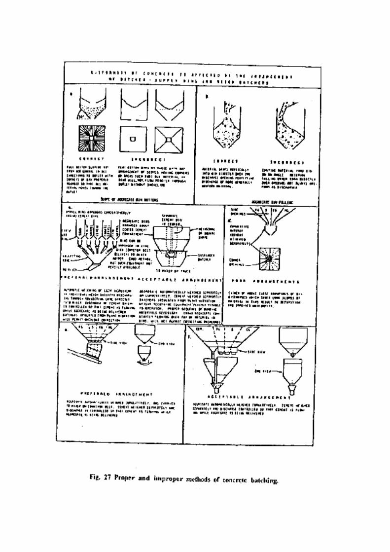
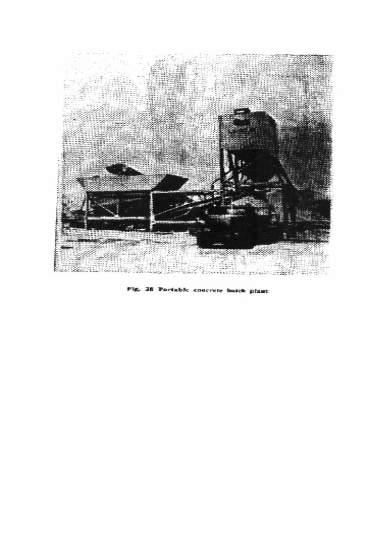
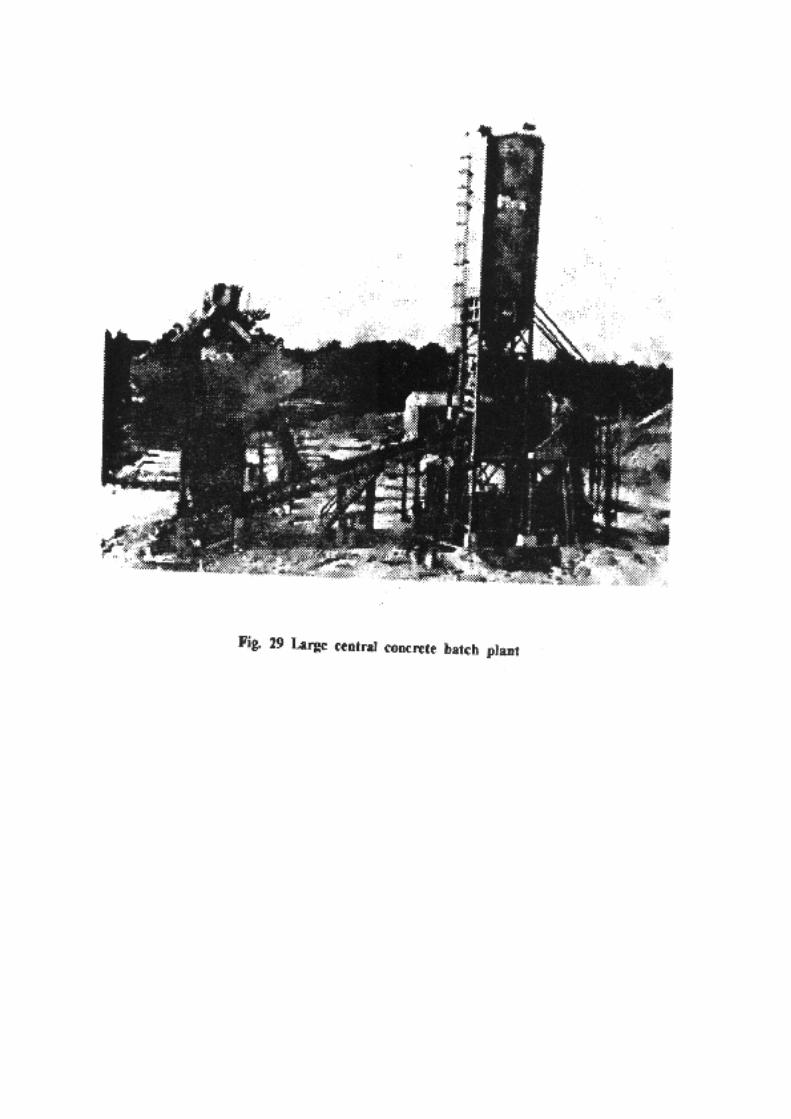
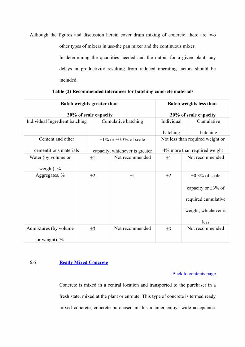
Although the figures and discussion herein cover drum mixing of concrete, there are two
other types of mixers in use-the pan mixer and the continuous mixer.
In determining the quantities needed and the output for a given plant, any
delays in productivity resulting from reduced operating factors should be
included.
Table (2) Recommended tolerances for batching concrete materials
Batch weights greater than
30% of scale capacity
Batch weights less than
30% of scale capacityIndividual Ingredient batching Cumulative batching Individual
batching
Cumulative
batchingCement and other
cementitious materials
1% or 0.3% of scale
capacity, whichever is greater
Not less than required weight or
4% more than required weightWater (by volume or
weight), %
1 Not recommended 1 Not recommended
Aggregates, % 2 1 2 0.3% of scale
capacity or 3% of
required cumulative
weight, whichever is
lessAdmixtures (by volume
or weight), %
3 Not recommended 3 Not recommended
6.6 Ready Mixed Concrete
Back to contents page
Concrete is mixed in a central location and transported to the purchaser in a
fresh state, mixed at the plant or enroute. This type of concrete is termed ready
mixed concrete, concrete purchased in this manner enjoys wide acceptance.
Obviously, to be useful, readymixed concrete must be available within a
reasonable distance from the project. On remote sites and sites requiring large
quantities of concrete, generally field concrete batch plants are used.
Concrete purchased from a ready-mixed concrete plant can be provided in
several ways. These include :
a) Central mixed concrete
This is concrete which is completely in a stationary mixer and
transported to the project either in a truck agitator, a truck mixer
operating at agitating speed, or in a non agitating truck.
b) Shrink-mixer concrete
This is concrete which is partially mixed in a stationary mixer and then
mixed completely in a truck mixer (usually en route to the project).
c) Truck-mixer concrete
This is concrete that is completely mixed in a truck mixer, with 70 to
100 revolutions to be at a speed sufficient to completely mix the
concrete. This type of concrete is usually termed transit-mixed concrete
because it is generally mixed en route.
Transit mixers are available in several sizes up to about 14 cu yd, but
the most popular size is 8 cu yd (fig.30). They are capable of
thoroughly mixing the concrete within about 100 revolutions of the
mixing drum at mixing speed (generally 8 to 12 rpm). This mixing
during transit usually results a stiffening the mixture, and the addition
of water is done at the job site to restore the slump, followed by
remixing. This has caused problem and raised questions concerning the
uniformity of ready-mixed concrete. Some of the water be withheld

until the mixer arrived at the project site (especially in hot weather),
then the remaining water be added and an additional 30 revolutions of
mixing be required. To offset any stiffening, small amounts of
additional water are permitted, provided the design water-cement ratio
is not exceeded. The uniformity requirements of ready mixed concrete
are given in Table 3.
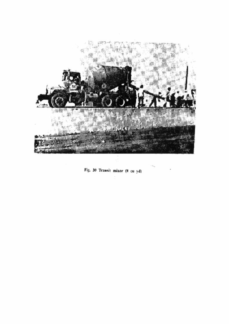
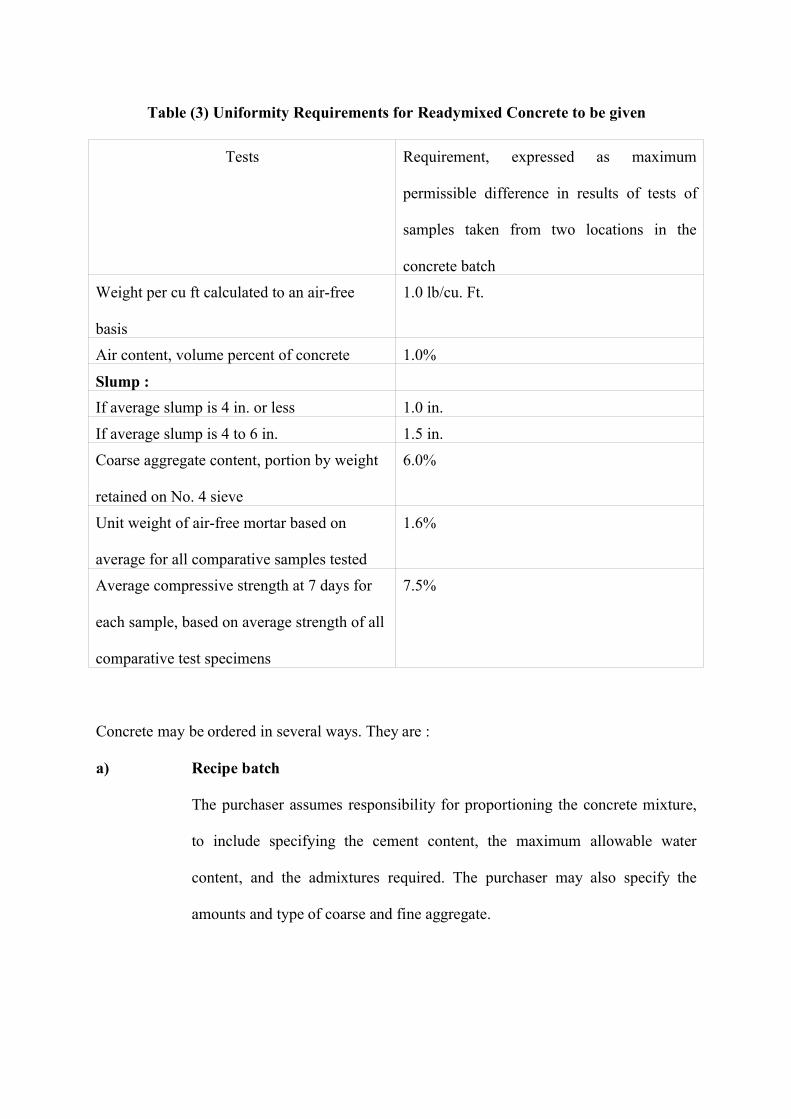
Table (3) Uniformity Requirements for Readymixed Concrete to be given
Tests Requirement, expressed as maximum
permissible difference in results of tests of
samples taken from two locations in the
concrete batch
Weight per cu ft calculated to an air-free
basis
1.0 lb/cu. Ft.
Air content, volume percent of concrete 1.0%
Slump :If average slump is 4 in. or less 1.0 in.
If average slump is 4 to 6 in. 1.5 in.
Coarse aggregate content, portion by weight
retained on No. 4 sieve
6.0%
Unit weight of air-free mortar based on
average for all comparative samples tested
1.6%
Average compressive strength at 7 days for
each sample, based on average strength of all
comparative test specimens
7.5%
Concrete may be ordered in several ways. They are :
a) Recipe batch
The purchaser assumes responsibility for proportioning the concrete mixture,
to include specifying the cement content, the maximum allowable water
content, and the admixtures required. The purchaser may also specify the
amounts and type of coarse and fine aggregate.
Under this approach, the purchaser assumes full responsibility for the resulting
strength and durability of the mixture, providing the stipulated amounts are
furnished as specified.
b) Performance batch
The purchaser specifies the requirements for the strength of the concrete, and
the manufacturer assumes full responsibility for the proportions of the various
ingredients that go into the batch.
c) Part performance and part recipe
The purchaser generally specifies a minimum cement content, the required
admixtures, and the strength requirements, allowing the manufacturer to
proportion the concrete mixture within the constraints imposed.
Today, most purchasers of concrete use the third approach, part performance
and part recipe, as it ensures a minimum durability while still allowing the
ready-mixed concrete supplier some flexibility to supply the most economical
mixture.
6.7 Moving and Placing Concrete
Back to contents page
Once the concrete arrives at the project site, it must be moved to its final
position without segregation and before it has achieved an initial set. This
movement may be accomplished in several ways, depending upon the distance,
elevation, and other constraints imposed. These methods include buckets or
hoppers, chutes and drop pipes, belt conveyors and concrete pumps.
a) Buckets or hoppers
Normally designed bottom dump buckets permit concrete placement at the
lowest practical slump (Fig.31). Care should be exercised to prevent the
concrete from segregating as a result of discharging from too high above the
surface or allowing the fresh concrete to fall past obstructions. Gates should be
designed so that they can be opened and closed at any time discharge of the
concrete.
b) Manual or motor propelled buggies
Hand buggies and wheelbarrows are usually capable of carrying from 4 to 9 cu
ft of concrete, and thus are suitable on many projects, provided there are
smooth and rigid runways upon, which to operate. Hand buggies are safer than
wheelbarrows because they have two wheels rather than one. Hand buggers
and wheelbarrows are recommended for distances less than 200 ft. while
power-driven or motor driven buggies-with capacities up to around 14 cu ft.,
can traverse up to 1,000 ft economically (see Fig.32).
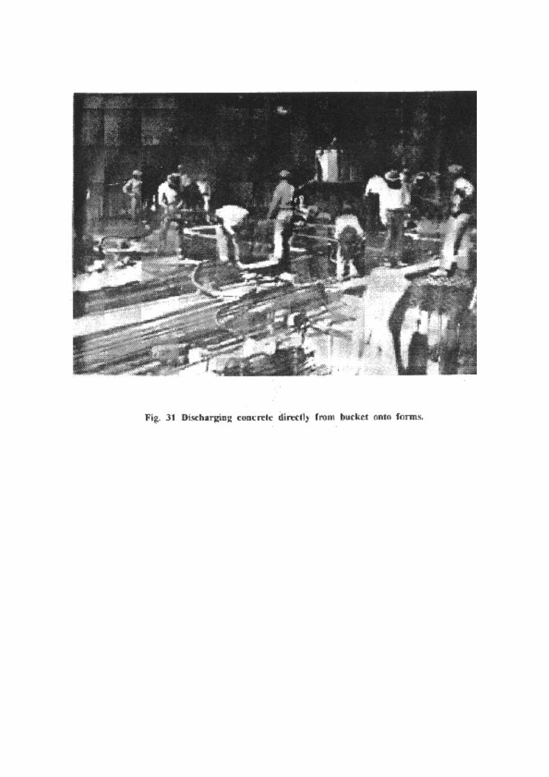
c) Chutes and drop pipes
Chutes are often used to transfer concrete from a higher elevation to a lower
elevation. They should have a round bottom, and the slope should be steep
enough for the concrete to -flow continuously without segregation. Drop
pipes are circular pipes used to transfer the concrete vertically. The pipe
should have a diameter at least eight times the maximum aggregate size at the
top 6 to 8 ft, and may be tapered to approximately six times the maximum
aggregate size. Drop pipes are usually used when concrete is placed in a wall
or column to avoid segregation from allowing the concrete to free-fall through
the reinforcement. In such areas, pipes should always be used.
d) Belt conveyors
Conveyors are classified into three types: (i) portable or self-contained
conveyors; (ii) feeders or series conveyors; and (iii) side-discharge or spreader
conveyors. All types must have the proper belt size and speed to achieve the
desired rate of placement. Fig.33 shows the use of several portable conveyors
to place concrete for a floor slab. This type of conveyor is capable of moving
large quantities of concrete rapidly. Particular attention must be given to points
where the concrete leaves one conveyor and either continues on another
conveyor or is discharged, as segregation can easily occur. Conveyors lend
themselves to moving concrete over long distances (Fig. 34) or up slopes
(Fig.35). The major disadvantage is the time necessary to set them up and to
change them. The optimum concrete slump for conveyors is from 2.5 to 3
inches.
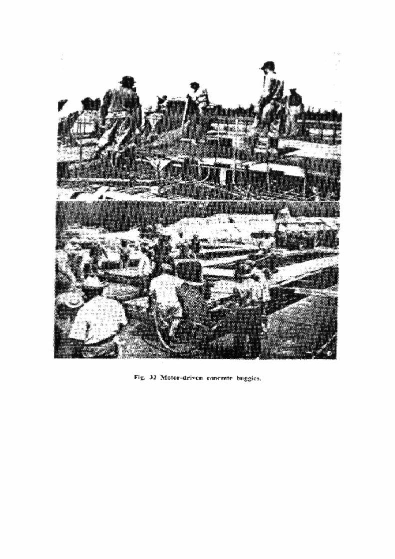
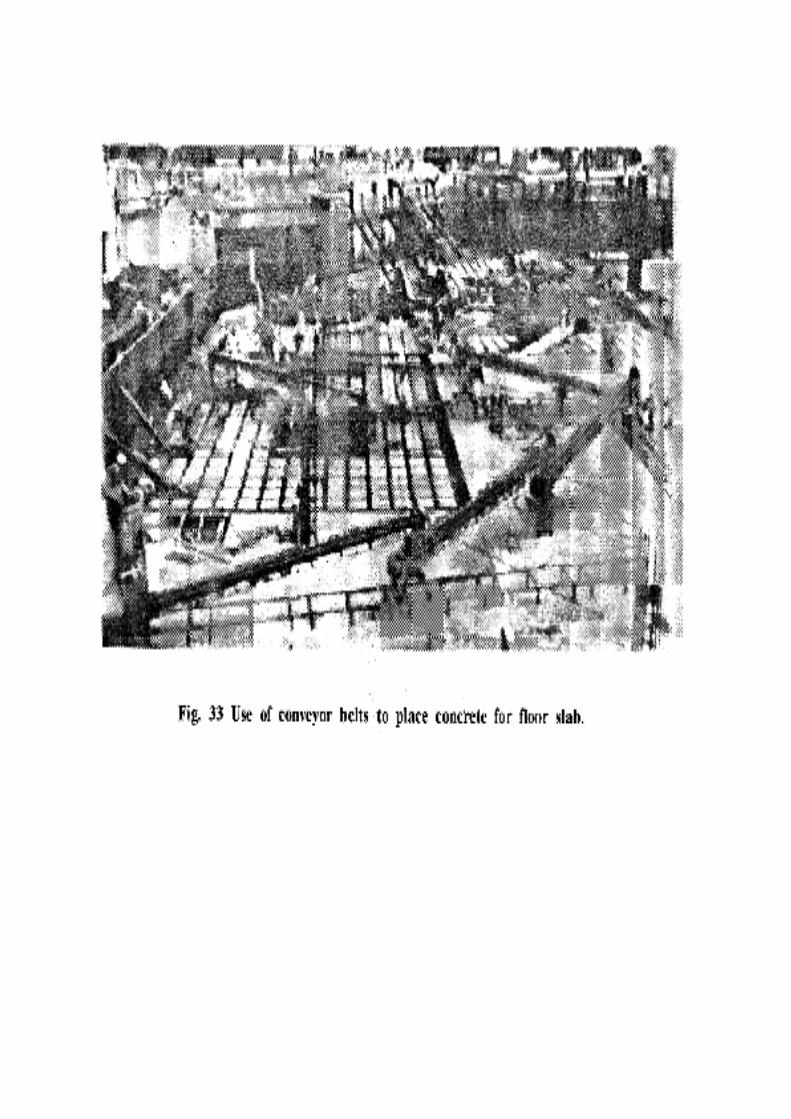
e) Concrete pumps
The placement of concrete through rigid or flexible lines is not new. The pump
is an extremely simple machine. By applying pressure to a column of fresh
concrete in a pipe, it can be moved through the pipe if a lubricating outer layer
is provided and if the mixture is properly proportioned for pumping. In order
to work properly, the pump must be fed with concrete of uniform workability
and consistency. Today, concrete pumping is one of the fastest growing
specialty contracting fields. Pumps are available in a variety of sizes, capable
of delivering concrete at sustained rates of 10 to 150 cu yd per hr. Effective
pumping range varies from 300 to 1,000 ft horizontally, or 100 to 300 ft
vertically, although occasionally pumps have moved concrete more than 5,000
ft horizontally and 1,000 ft vertically.
Pumps require a steady supply of pumpable concrete to be effective. Today
there are three types of pumps being manufactured: piston pumps, pneumatic
pumps, and squeeze pressure pumps. They are shown diagrammatically in Fig.
36 (a), (b) and (c) , respectively. Most piston pumps today contain two pistons,
with one retracting during the forward stroke of the other to give a more
continuous flow of concrete. The pneumatic pumps normally use a reblending
discharge box at the discharge end to bleed off the air and to prevent
segregation and spraying. In squeeze pressure pumps, hydraulically powered
rollers rotate on the flexible hose within the drum and squeeze the concrete out
at the top. The vacuum keeps a steady supply of concrete in the tube from the
receiving hopper.
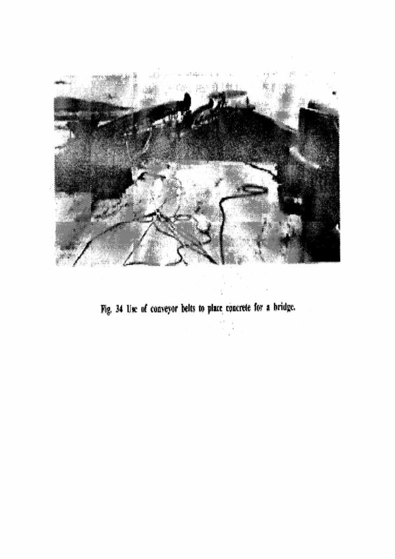
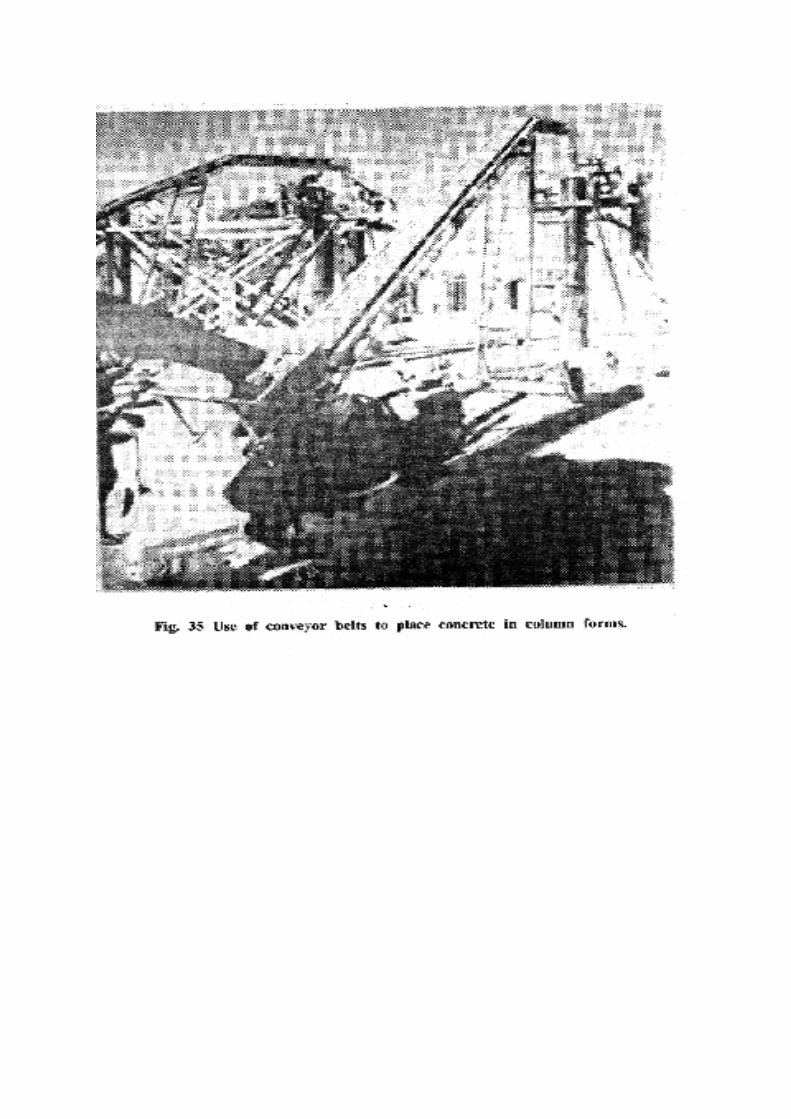
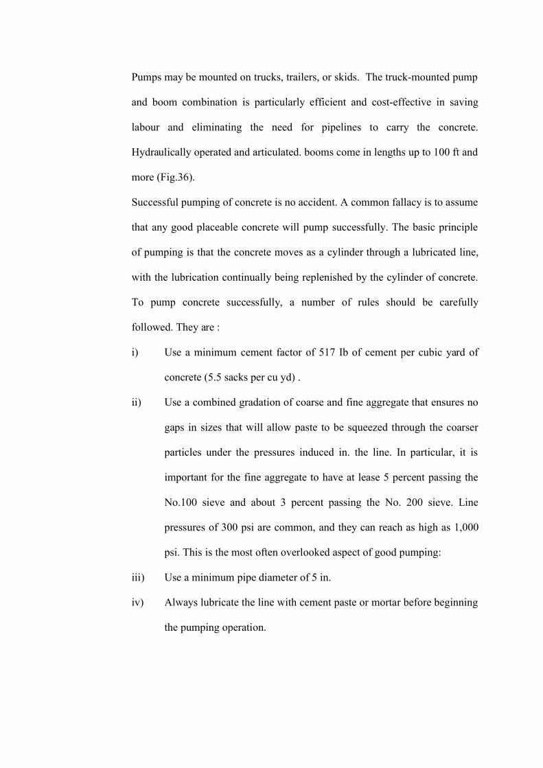
Pumps may be mounted on trucks, trailers, or skids. The truck-mounted pump
and boom combination is particularly efficient and cost-effective in saving
labour and eliminating the need for pipelines to carry the concrete.
Hydraulically operated and articulated. booms come in lengths up to 100 ft and
more (Fig.36).
Successful pumping of concrete is no accident. A common fallacy is to assume
that any good placeable concrete will pump successfully. The basic principle
of pumping is that the concrete moves as a cylinder through a lubricated line,
with the lubrication continually being replenished by the cylinder of concrete.
To pump concrete successfully, a number of rules should be carefully
followed. They are :
i) Use a minimum cement factor of 517 Ib of cement per cubic yard of
concrete (5.5 sacks per cu yd) .
ii) Use a combined gradation of coarse and fine aggregate that ensures no
gaps in sizes that will allow paste to be squeezed through the coarser
particles under the pressures induced in. the line. In particular, it is
important for the fine aggregate to have at lease 5 percent passing the
No.100 sieve and about 3 percent passing the No. 200 sieve. Line
pressures of 300 psi are common, and they can reach as high as 1,000
psi. This is the most often overlooked aspect of good pumping:
iii) Use a minimum pipe diameter of 5 in.
iv) Always lubricate the line with cement paste or mortar before beginning
the pumping operation.
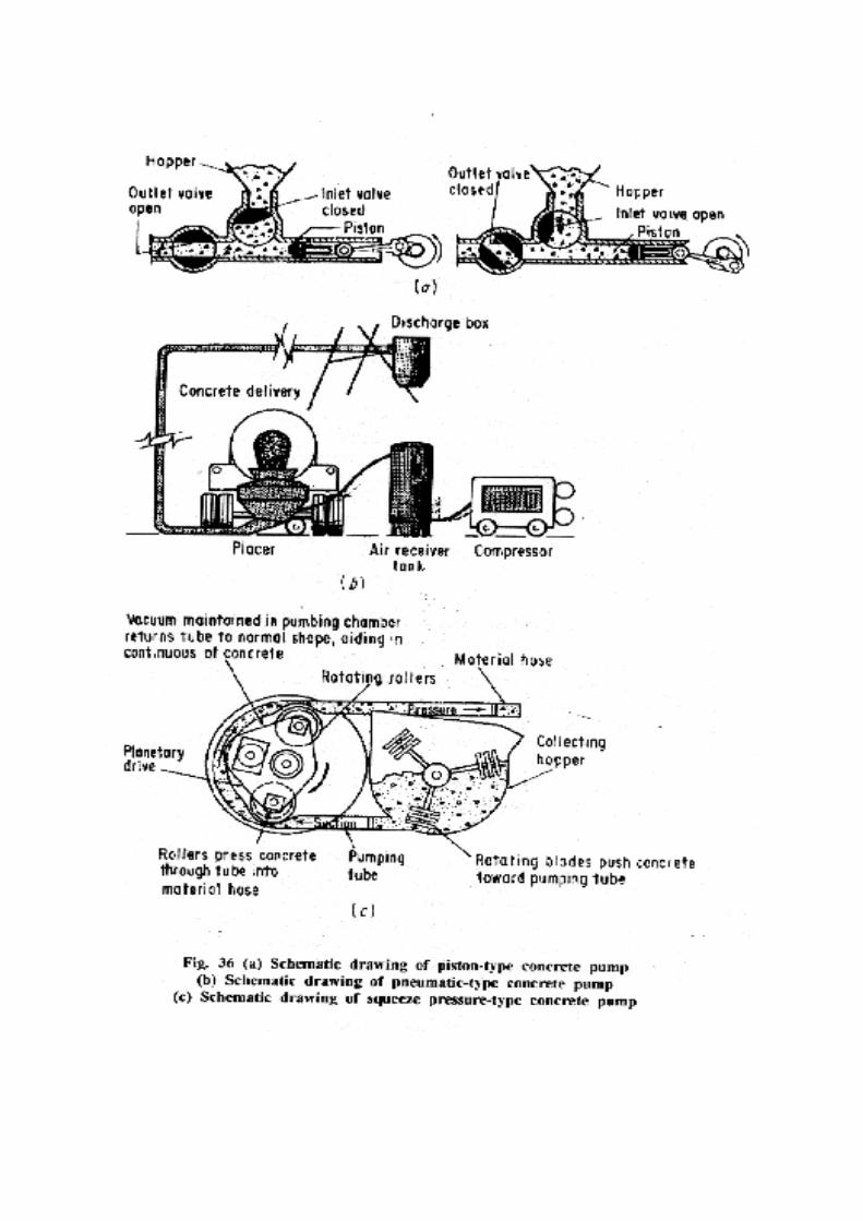
v) Ensure a steady, uniform supply of concrete, with a slump of between
2 and 5 as and it enters the pump.
vi) Always presoak the aggregates before mixing them in the concrete to
prevent their soaking up mix water under the imposed pressure. This is
especially important when aggregates are used which have a high
absorption (such as structural lightweight aggregate).
vii) Avoid the use of reducers in the conduit line. One common problem is
the use of a 5-in to 4-in reducer at the discharge end so that workers
will have only a 4 in, flexible hose to move around. This creates a
obstruction and significantly raises the pressure necessary to pump the
concrete.
viii) Never use aluminum lines. Aluminium particles will be scraped from
the inside of the pipe as the concrete moves through and will become
part of the concrete. Aluminum and portland cement react, liberating
hydrogen gas, which can rupture the concrete - with disastrous results.
6.8 Consolidating Concrete
Back to contents page
Concrete, being a heterogeneous mixture of water and solid particles in a stiff
condition, will normally contain a large quantity, of voids when placed into the
forms. It is the purpose of consolidation to remove these entrapped air voids.
The importance of proper consolidation cannot be overemphasized, as
entrapped air can render the concrete totally unstable. Entrapped air, can be
reduced two ways - use more water or consolidate the concrete. Fig. 37 shows
qualitatively the benefits of consolidation, especially on low-water -content
concrete.
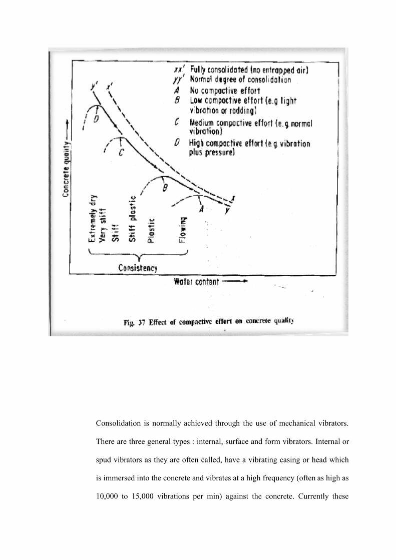
Consolidation is normally achieved through the use of mechanical vibrators.
There are three general types : internal, surface and form vibrators. Internal or
spud vibrators as they are often called, have a vibrating casing or head which
is immersed into the concrete and vibrates at a high frequency (often as high as
10,000 to 15,000 vibrations per min) against the concrete. Currently these
vibrators are the rotary type and come in sizes from 3/4 in. to 7 in. (Fig. 38).
They are powered by electric motors or compressed air. Manufacturers have
extensive data on their vibrators.
Surface vibrators exert their effects at the top surface of the concrete and
consolidate the concrete from the top down. They are used mainly in slab
construction, and there are four general types: the vibrating screed, the pan-
type vibrator, the plate or grid vibratory tamper, and the vibratory rolling
screed. These surface vibrators operate in the range of 3,000 to 6,000
vibrations per min.
Form vibrators are external vibrators attached to the outside of the form or
mold. They vibrate the form, which in turn vibrates the concrete. These types
of vibrators are generally used in large precast concrete plants.
6.9 Recommended vibration practices
Back to contents page
Internal vibration is generally best suited for ordinary construction provided
the section is large enough for the vibrator to be manipulated. As each vibrator
has an effective radius of action, vibrator insertions should be vertical at about
1.5 times the radius of action. The vibrator should never be used to move
concrete laterally, as segregation can easily occur. The vibrator should be
rapidly inserted to the bottom of the layer (usually 12 to 18 in. maximum lift
thickness) and at least 6 in. into the previous layer. It should then be held
stationary for about 5 to 15 sec until the consolidation is considered adequate.
The vibrator should then be withdrawn slowly. Where several layers are being
placed, each layer should be placed while the preceding layer is still plastic.
Vibration accomplishes two actions. First, it "slumps" the concrete, removing
a large portion of air that is entrapped when the concrete is deposited. Then,
continued vibration consolidates the concrete, removing most of the remaining
entrapped air. Generally, it will not remove entrained air. The question
concerning over vibration is often raised: When does it occur and how harmful
is it? The fact is that on low-slump concrete (concrete with less than 3 in
slump) it is almost impossible to overvibrate it with internal vibrators: When
in doubt as to how much vibration to impart to low-slump concrete, vibrate it
some more. The same cannot be said of concrete whose slump is 3 in. or more.
This concrete can be overvibrated, which results in segregation as a result of
coarse aggregate moving away from the vibrating head. Here the operator
should note the pressure of air bubbles escaping to the concrete surface as the
vibrator is inserted. When these bubbles cease, vibration is generally complete
and the vibrator should be withdrawn. Another point of caution concerns
surface vibrators. They too can overvibrate the concrete at the surface,
significantly weakening it if they remain in one place too long.
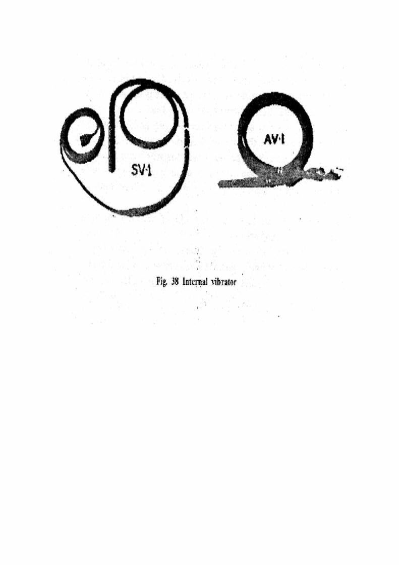
Another concern is the vibration of reinforcing steel. Such vibration improves the bond
between the reinforcing steel and the concrete/and thus is desirable. The
undesirable side effects 'include damage to the vibrator and possible
movement of the steel from its intended position.
Finally, revibration is the process whereby the concrete is vibrated again after
it has been allowed to remain undisturbed for some time. Such revibration can
be accomplished at any time. The running vibrator will sink of its own weight
into the concrete and liquefy it momentarily. Such revibration will i.-nprove
the concrete through increased consolidation.
6.10 Finishing and Curing Concrete
Back to contents page
It cannot be stated too strongly that any work you do to a concrete surface after
it has been consolidated will weaken the surface. All too often, concrete
technicians overlook this fact and manipulate the surface of the concrete to
produce a smooth, attractive surface. On walls and columns, an attractive
surface may be desirable and the surface strength may not be too important,
but on a floor slab, sidewalk, or pavement, the surface strength is very
important. On the latter types of'surfaces only the absolute minimum finishing
necessary to impart the desired texture should be permitted, and the use of
"jitterbugging" (the forcing of coarse aggregate down into the concrete with a
steel grate tool) should not be permitted, as the surface can be weakened
significantly. Furthermore, each step in the finishing operation, from first
floating to the final floating or troweling, should be delayed as long as possible
and still permit the desired grade and surface smoothness to be obtained. In no
case should neat cement or mixtures of sand and cement be worked into such
surfaces to dry them up.
Along with placement and consolidation, proper curing of the concrete is
extremely important. Curing may be considered as the method whereby the
concrete is assured of adequate time, temperature, and supply of water for the
cement to continue to hydrate. The time normally required is 3 days, and
optimum temperatures are between 40 and 800F. As most concrete is batched
with sufficient water for hydration, the only problem is to ensure that the
concrete does not become dried out. This may be accomplished by ponding
with water (for slabs), covering with burlap or polyethylene sheets or spraying
with an approved curing compound. Curing is one of the least costly
operations in the production of quality concrete, and one that is all too
frequently overlooked. Concrete, if allowed to dry out during the curing stage,
will attempt to shrink. The developing bonds from the cementitious reaction
will attempt to restrain the shrinkage from taking place. But the end result is
always the same: the shrinkage wins out and a crack forms as the shrinkage
stress are always higher than the tensile strength of the concrete. Proper curing
does reduce the detrimental effects of cracking and develops the intended
strength of the concrete.
6.11 Placing Concrete in Cold Weather
Back to contents page
When concrete is placed in cold weather, some provision must be made to
keep the concrete above freezing during the first few days after it has been
placed. Specifications generally require that the concrete be kept at not less
than 700F for 3 days or not less than 500F for 5 days after placement.
Preheating the water is generally the most effective method of providing the
necessary temperature for placement.
When the temperatures of the ingredients are known, the chart in Fig. 3 9 may be used to
determine the temperature of concrete. A straight line across all three scales,
passing through any two known tempera-tures, will permit the determination
of the third temperature. If the sand is surface-dry, the solid lines of the scales
giving the temperature of concrete should be used. However, if the sand
contains about 3 percent moisture, the dotted lines should be used.
6.12 Placing Concrete in Hot Weather
Back to contents page
When the temperature of, fresh concrete exceeds" around 85 to 900F, the
resulting strength and durability of the concrete can be reduced. Therefore
most specifications require the concrete to be placed at a temperature less than
900F. When concrete is placed in hot weather, the ingredients should be cooled
before mixing. Methods of cooling include using ice instead of water in the
mix and cooling the aggregate with liquid nitrogen.
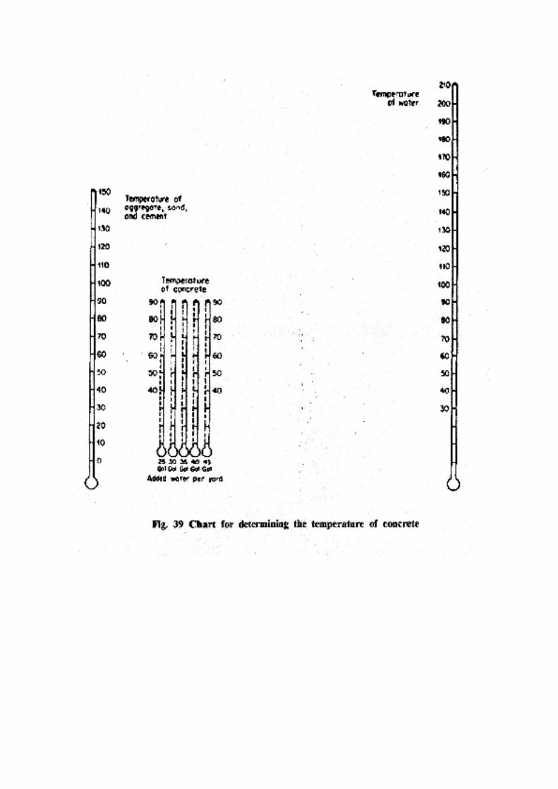
CHAPTER-7
Mechanised Construction
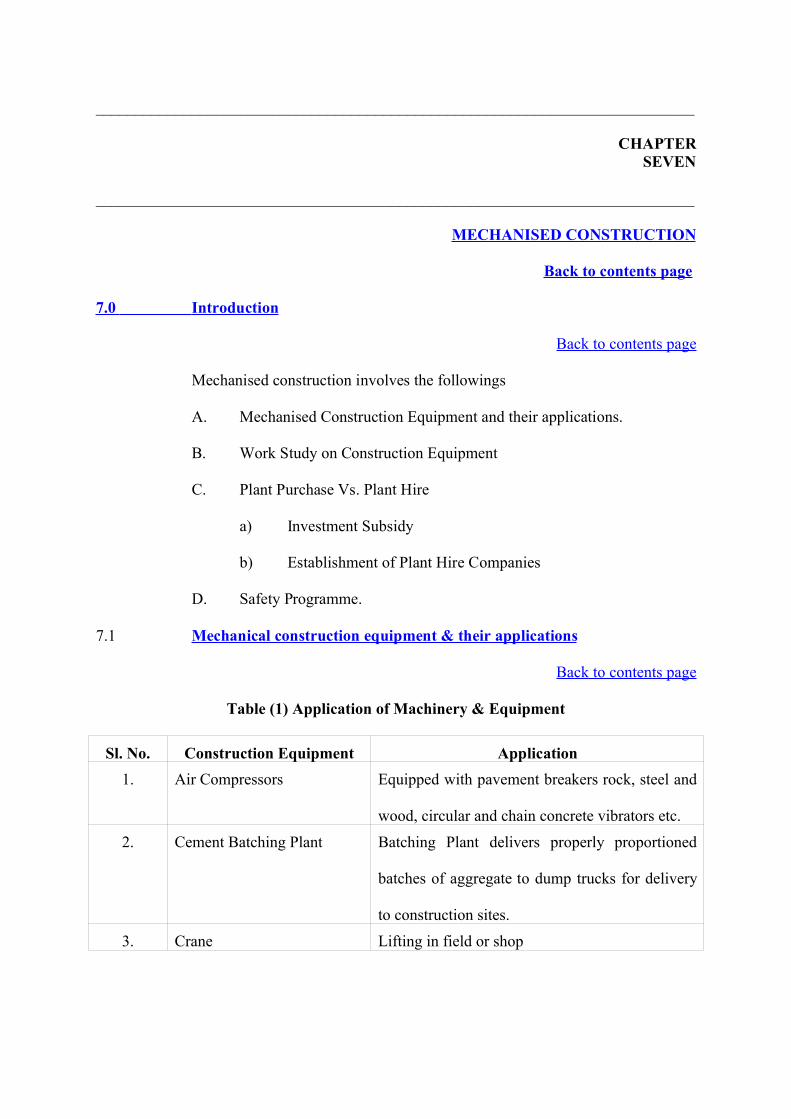
___________________________________________________________________________
CHAPTERSEVEN
___________________________________________________________________________
MECHANISED CONSTRUCTION
Back to contents page
7.0 Introduction
Back to contents page
Mechanised construction involves the followings
A. Mechanised Construction Equipment and their applications.
B. Work Study on Construction Equipment
C. Plant Purchase Vs. Plant Hire
a) Investment Subsidy
b) Establishment of Plant Hire Companies
D. Safety Programme.
7.1 Mechanical construction equipment & their applications
Back to contents page
Table (1) Application of Machinery & Equipment
Sl. No. Construction Equipment Application1. Air Compressors Equipped with pavement breakers rock, steel and
wood, circular and chain concrete vibrators etc.
2. Cement Batching Plant Batching Plant delivers properly proportioned
batches of aggregate to dump trucks for delivery
to construction sites.
3. Crane Lifting in field or shop
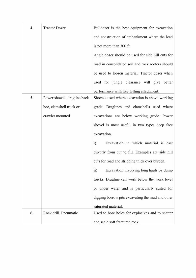
4. Tractor Dozer Bulldozer is the best equipment for excavation
and construction of embankment where the lead
is not more than 300 ft.
Angle dozer should be used for side hill cuts for
road in consolidated soil and rock rooters should
be used to loosen material. Tractor dozer when
used for jungle clearance will give better
performance with tree felling attachment.
5. Power showel, dragline back
hoe, clamshell truck or
crawler mounted
Shovels used where excavation is above working
grade. Draglines and clamshells used where
excavations are below working grade. Power
shovel is most useful in two types deep face
excavation.
i) Excavation in which material is cast
directly from cut to fill. Examples are side hill
cuts for road and stripping thick over burden.
ii) Excavation involving long hauls by dump
trucks. Dragline can work below the work level
or under water and is particularly suited for
digging borrow pits excavating the mud and other
saturated material.
6. Rock drill, Pneumatic Used to bore holes for explosives and to shatter
and scale soft fractured rock.
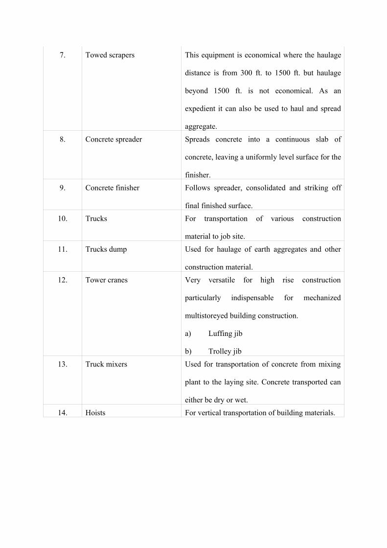
7. Towed scrapers This equipment is economical where the haulage
distance is from 300 ft. to 1500 ft. but haulage
beyond 1500 ft. is not economical. As an
expedient it can also be used to haul and spread
aggregate.
8. Concrete spreader Spreads concrete into a continuous slab of
concrete, leaving a uniformly level surface for the
finisher.
9. Concrete finisher Follows spreader, consolidated and striking off
final finished surface.
10. Trucks For transportation of various construction
material to job site.
11. Trucks dump Used for haulage of earth aggregates and other
construction material.
12. Tower cranes Very versatile for high rise construction
particularly indispensable for mechanized
multistoreyed building construction.
a) Luffing jib
b) Trolley jib
13. Truck mixers Used for transportation of concrete from mixing
plant to the laying site. Concrete transported can
either be dry or wet.
14. Hoists For vertical transportation of building materials.
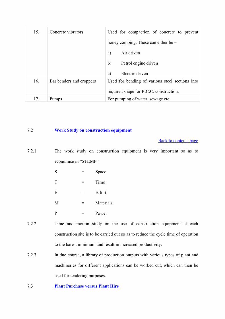
15. Concrete vibrators Used for compaction of concrete to prevent
honey combing. These can either be –
a) Air driven
b) Petrol engine driven
c) Electric driven
16. Bar benders and croppers Used for bending of various steel sections into
required shape for R.C.C. construction.
17. Pumps For pumping of water, sewage etc.
7.2 Work Study on construction equipment
Back to contents page
7.2.1 The work study on construction equipment is very important so as to
economise in “STEMP”.
S = Space
T = Time
E = Effort
M = Materials
P = Power
7.2.2 Time and motion study on the use of construction equipment at each
construction site is to be carried out so as to reduce the cycle time of operation
to the barest minimum and result in increased productivity.
7.2.3 In due course, a library of production outputs with various types of plant and
machineries for different applications can be worked cut, which can then be
used for tendering purposes.
7.3 Plant Purchase versus Plant Hire

Back to contents page
Since the purchase of construction plant and equipment involves considerable
capital outlay, judicious decision is to be taken on purchase of construction
plant versus plant hire at various sites of work. Needless to mention, for large
jobs involving spread over number of years, it may be ultimately economical
to buy the equipment but for jobs involving short term use, plant hire is more
economical. There are two issues which must be highlighted in this
connection.
7.3.1 Investment subsidy
Unfortunately, in our country, no investment subsidy is given by the
Government to contractors or plant owners. Even in an advanced country like
U.K., the Government gives subsidy to extent of 45% of the cost of the plant
in underdeveloped areas and 25% of the cost of the plant elsewhere as out
right grant. There is, therefore, considerable incentive to the builders to go in
for mechanization which results in up-gradation of technology and better
quality of work.
7.3.2 Establishment of Plant Hire companies
The concept of plant hire companies on a large scale has still not caught up in
our country. Abroad, it is very common for individual entrepreneurs to own a
few contracts’ Plant and Machinery and give them on hire to prospective
builders. In fact, young engineering graduates and private entrepreneurs should
be encouraged to come out in this profession of owing contractors’ plant and
machinery and rent them out to contracting Companies and Builders. In a
small country like Cyprus, there are three private parties owning and running
ready mix concrete plants and they are in business of selling RMC to
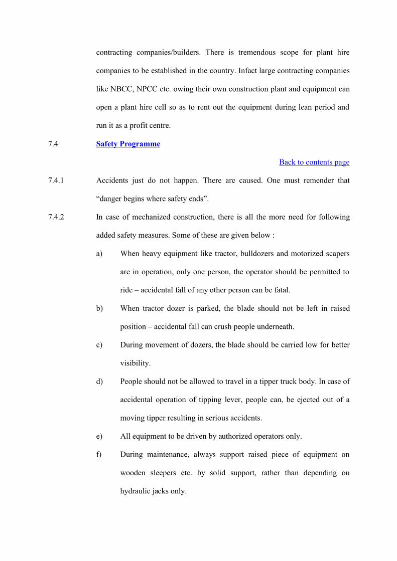
contracting companies/builders. There is tremendous scope for plant hire
companies to be established in the country. Infact large contracting companies
like NBCC, NPCC etc. owing their own construction plant and equipment can
open a plant hire cell so as to rent out the equipment during lean period and
run it as a profit centre.
7.4 Safety Programme
Back to contents page
7.4.1 Accidents just do not happen. There are caused. One must remender that
“danger begins where safety ends”.
7.4.2 In case of mechanized construction, there is all the more need for following
added safety measures. Some of these are given below :
a) When heavy equipment like tractor, bulldozers and motorized scapers
are in operation, only one person, the operator should be permitted to
ride – accidental fall of any other person can be fatal.
b) When tractor dozer is parked, the blade should not be left in raised
position – accidental fall can crush people underneath.
c) During movement of dozers, the blade should be carried low for better
visibility.
d) People should not be allowed to travel in a tipper truck body. In case of
accidental operation of tipping lever, people can, be ejected out of a
moving tipper resulting in serious accidents.
e) All equipment to be driven by authorized operators only.
f) During maintenance, always support raised piece of equipment on
wooden sleepers etc. by solid support, rather than depending on
hydraulic jacks only.
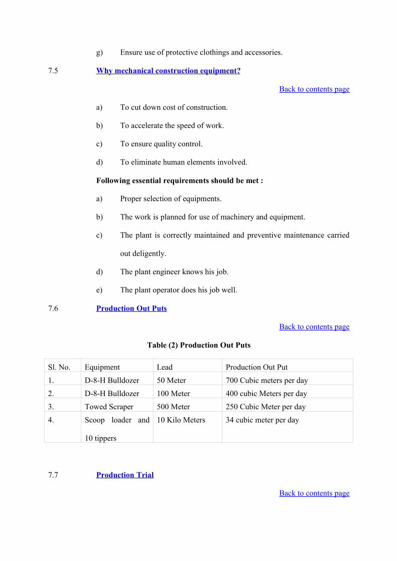
g) Ensure use of protective clothings and accessories.
7.5 Why mechanical construction equipment?
Back to contents page
a) To cut down cost of construction.
b) To accelerate the speed of work.
c) To ensure quality control.
d) To eliminate human elements involved.
Following essential requirements should be met :
a) Proper selection of equipments.
b) The work is planned for use of machinery and equipment.
c) The plant is correctly maintained and preventive maintenance carried
out deligently.
d) The plant engineer knows his job.
e) The plant operator does his job well.
7.6 Production Out Puts
Back to contents page
Table (2) Production Out Puts
Sl. No. Equipment Lead Production Out Put
1. D-8-H Bulldozer 50 Meter 700 Cubic meters per day
2. D-8-H Bulldozer 100 Meter 400 cubic Meters per day
3. Towed Scraper 500 Meter 250 Cubic Meter per day
4. Scoop loader and
10 tippers
10 Kilo Meters 34 cubic meter per day
7.7 Production Trial
Back to contents page
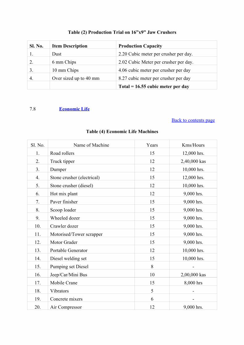
Table (2) Production Trial on 16”x9” Jaw Crushers
Sl. No. Item Description Production Capacity1. Dust 2.20 Cubic meter per crusher per day.
2. 6 mm Chips 2.02 Cubic Meter per crusher per day.
3. 10 mm Chips 4.06 cubic meter per crusher per day
4. Over sized up to 40 mm 8.27 cubic meter per crusher per day
Total = 16.55 cubic meter per day
7.8 Economic Life
Back to contents page
Table (4) Economic Life Machines
Sl. No. Name of Machine Years Kms/Hours
1. Road rollers 15 12,000 hrs.
2. Truck tipper 12 2,40,000 kas
3. Dumper 12 10,000 hrs.
4. Stone crusher (electrical) 15 12,000 hrs.
5. Stone crusher (diesel) 12 10,000 hrs.
6. Hot mix plant 12 9,000 hrs.
7. Paver finisher 15 9,000 hrs.
8. Scoop loader 15 9,000 hrs.
9. Wheeled dozer 15 9,000 hrs.
10. Crawler dozer 15 9,000 hrs.
11. Motorised/Tower scrapper 15 9,000 hrs.12. Motor Grader 15 9,000 hrs.
13. Portable Generator 12 10,000 hrs.
14. Diesel welding set 15 10,000 hrs.
15. Pumping set Diesel 8 -
16. Jeep/Car/Mini Bus 10 2,00,000 kas
17. Mobile Crane 15 8,000 hrs
18. Vibrators 5 -
19. Concrete mixers 6 -
20. Air Compressor 12 9,000 hrs.


CHAPTER-8
Standard Field Quality Plan
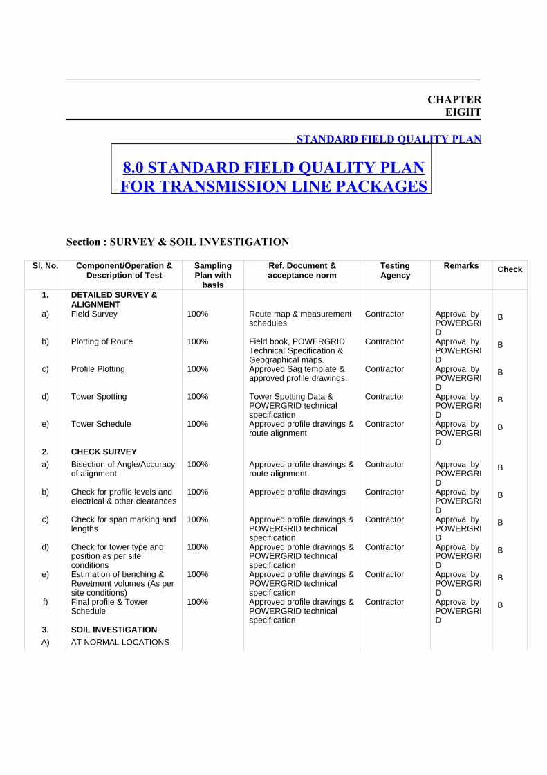
___________________________________________________________________________
CHAPTEREIGHT
STANDARD FIELD QUALITY PLAN
8.0 STANDARD FIELD QUALITY PLANFOR TRANSMISSION LINE PACKAGES
Section : SURVEY & SOIL INVESTIGATION
Sl. No. Component/Operation &Description of Test
SamplingPlan with
basis
Ref. Document &acceptance norm
TestingAgency
Remarks Check
1. DETAILED SURVEY &ALIGNMENT
a) Field Survey 100% Route map & measurementschedules
Contractor Approval byPOWERGRID
B
b) Plotting of Route 100% Field book, POWERGRIDTechnical Specification &Geographical maps.
Contractor Approval byPOWERGRID
B
c) Profile Plotting 100% Approved Sag template &approved profile drawings.
Contractor Approval byPOWERGRID
B
d) Tower Spotting 100% Tower Spotting Data &POWERGRID technicalspecification
Contractor Approval byPOWERGRID
B
e) Tower Schedule 100% Approved profile drawings &route alignment
Contractor Approval byPOWERGRID
B
2. CHECK SURVEY
a) Bisection of Angle/Accuracyof alignment
100% Approved profile drawings &route alignment
Contractor Approval byPOWERGRID
B
b) Check for profile levels andelectrical & other clearances
100% Approved profile drawings Contractor Approval byPOWERGRID
B
c) Check for span marking andlengths
100% Approved profile drawings &POWERGRID technicalspecification
Contractor Approval byPOWERGRID
B
d) Check for tower type andposition as per siteconditions
100% Approved profile drawings &POWERGRID technicalspecification
Contractor Approval byPOWERGRID
B
e) Estimation of benching &Revetment volumes (As persite conditions)
100% Approved profile drawings &POWERGRID technicalspecification
Contractor Approval byPOWERGRID
B
f) Final profile & TowerSchedule
100% Approved profile drawings &POWERGRID technicalspecification
Contractor Approval byPOWERGRID
B
3. SOIL INVESTIGATION
A) AT NORMAL LOCATIONS

i) Borelog/Trial pit All other thanangle, rivercrossing &speciallocations
POWERGRID technicalspecification & relevant IS
Contractor/POWERGRIDapproved lab.
Approval byPOWERGRID.POWERGRID to witnessfor a min.25% oflocations
B
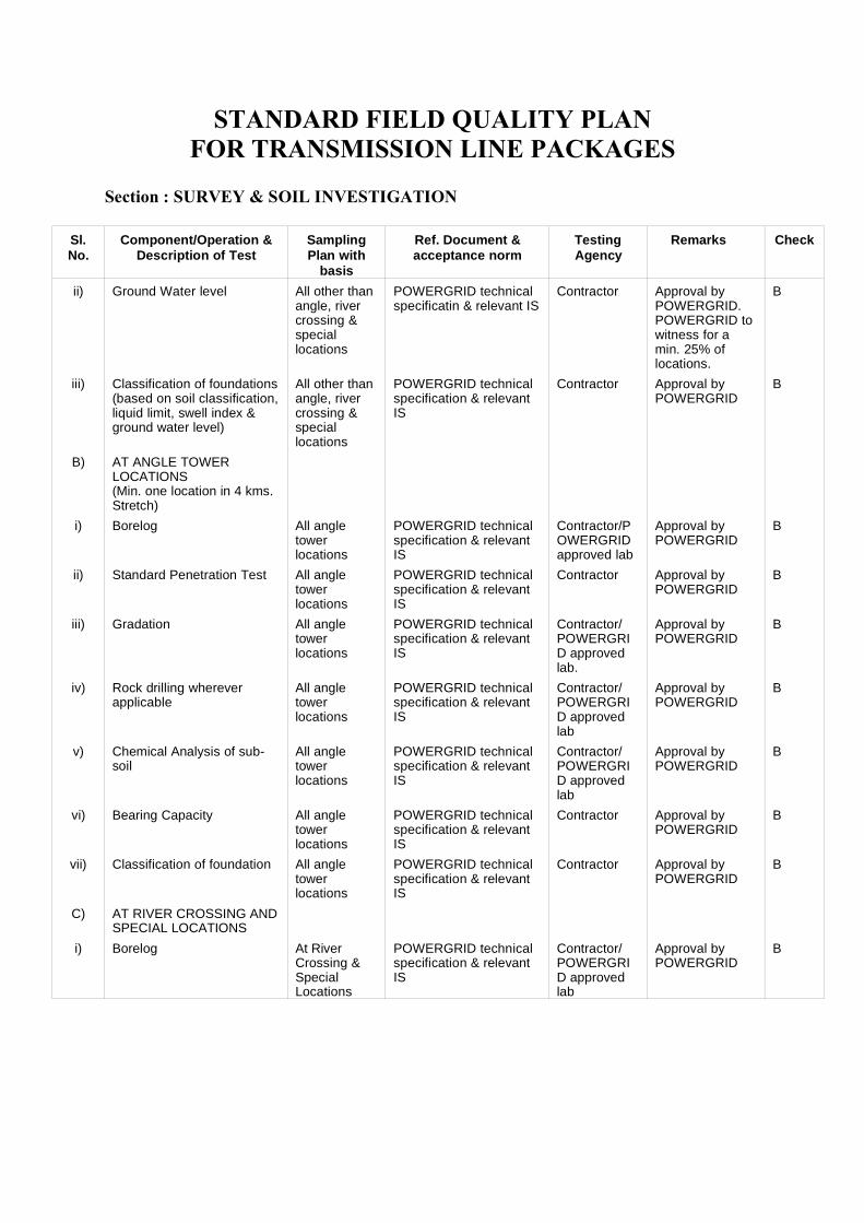
STANDARD FIELD QUALITY PLANFOR TRANSMISSION LINE PACKAGES
Section : SURVEY & SOIL INVESTIGATION
Sl.No.
Component/Operation &Description of Test
SamplingPlan with
basis
Ref. Document &acceptance norm
TestingAgency
Remarks Check
ii) Ground Water level All other thanangle, rivercrossing &speciallocations
POWERGRID technicalspecificatin & relevant IS
Contractor Approval byPOWERGRID.POWERGRID towitness for amin. 25% oflocations.
B
iii) Classification of foundations(based on soil classification,liquid limit, swell index &ground water level)
All other thanangle, rivercrossing &speciallocations
POWERGRID technicalspecification & relevantIS
Contractor Approval byPOWERGRID
B
B) AT ANGLE TOWERLOCATIONS (Min. one location in 4 kms.Stretch)
i) Borelog All angletowerlocations
POWERGRID technicalspecification & relevantIS
Contractor/POWERGRIDapproved lab
Approval byPOWERGRID
B
ii) Standard Penetration Test All angletowerlocations
POWERGRID technicalspecification & relevantIS
Contractor Approval byPOWERGRID
B
iii) Gradation All angletowerlocations
POWERGRID technicalspecification & relevantIS
Contractor/POWERGRID approvedlab.
Approval byPOWERGRID
B
iv) Rock drilling whereverapplicable
All angletowerlocations
POWERGRID technicalspecification & relevantIS
Contractor/POWERGRID approvedlab
Approval byPOWERGRID
B
v) Chemical Analysis of sub-soil
All angletowerlocations
POWERGRID technicalspecification & relevantIS
Contractor/POWERGRID approvedlab
Approval byPOWERGRID
B
vi) Bearing Capacity All angletowerlocations
POWERGRID technicalspecification & relevantIS
Contractor Approval byPOWERGRID
B
vii) Classification of foundation All angletowerlocations
POWERGRID technicalspecification & relevantIS
Contractor Approval byPOWERGRID
B
C) AT RIVER CROSSING ANDSPECIAL LOCATIONS
i) Borelog At RiverCrossing &SpecialLocations
POWERGRID technicalspecification & relevantIS
Contractor/POWERGRID approvedlab
Approval byPOWERGRID
B
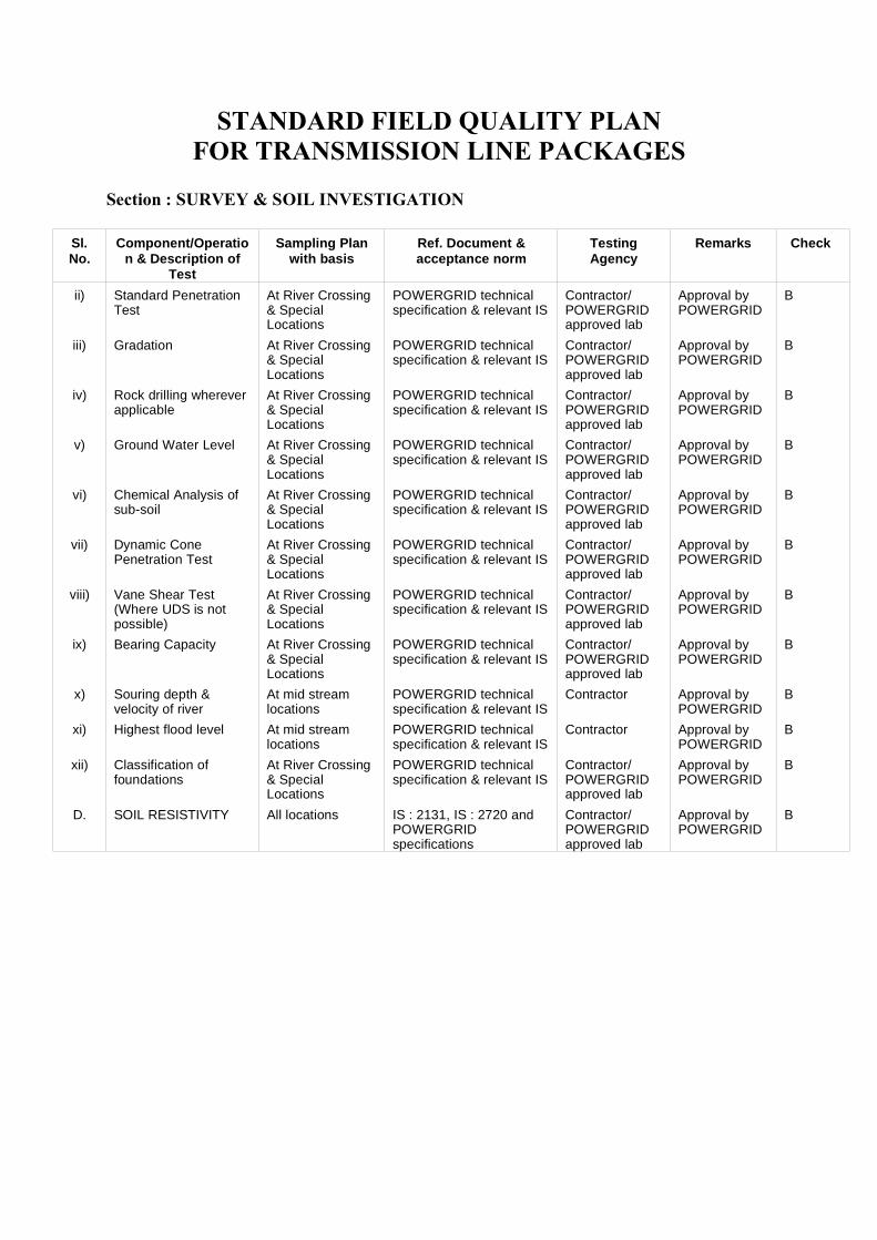
STANDARD FIELD QUALITY PLANFOR TRANSMISSION LINE PACKAGES
Section : SURVEY & SOIL INVESTIGATION
Sl.No.
Component/Operation & Description of
Test
Sampling Planwith basis
Ref. Document &acceptance norm
TestingAgency
Remarks Check
ii) Standard PenetrationTest
At River Crossing& SpecialLocations
POWERGRID technicalspecification & relevant IS
Contractor/POWERGRIDapproved lab
Approval byPOWERGRID
B
iii) Gradation At River Crossing& SpecialLocations
POWERGRID technicalspecification & relevant IS
Contractor/POWERGRIDapproved lab
Approval byPOWERGRID
B
iv) Rock drilling whereverapplicable
At River Crossing& SpecialLocations
POWERGRID technicalspecification & relevant IS
Contractor/POWERGRIDapproved lab
Approval byPOWERGRID
B
v) Ground Water Level At River Crossing& SpecialLocations
POWERGRID technicalspecification & relevant IS
Contractor/POWERGRIDapproved lab
Approval byPOWERGRID
B
vi) Chemical Analysis ofsub-soil
At River Crossing& SpecialLocations
POWERGRID technicalspecification & relevant IS
Contractor/POWERGRIDapproved lab
Approval byPOWERGRID
B
vii) Dynamic ConePenetration Test
At River Crossing& SpecialLocations
POWERGRID technicalspecification & relevant IS
Contractor/POWERGRIDapproved lab
Approval byPOWERGRID
B
viii) Vane Shear Test(Where UDS is notpossible)
At River Crossing& SpecialLocations
POWERGRID technicalspecification & relevant IS
Contractor/POWERGRIDapproved lab
Approval byPOWERGRID
B
ix) Bearing Capacity At River Crossing& SpecialLocations
POWERGRID technicalspecification & relevant IS
Contractor/POWERGRIDapproved lab
Approval byPOWERGRID
B
x) Souring depth &velocity of river
At mid streamlocations
POWERGRID technicalspecification & relevant IS
Contractor Approval byPOWERGRID
B
xi) Highest flood level At mid streamlocations
POWERGRID technicalspecification & relevant IS
Contractor Approval byPOWERGRID
B
xii) Classification offoundations
At River Crossing& SpecialLocations
POWERGRID technicalspecification & relevant IS
Contractor/POWERGRIDapproved lab
Approval byPOWERGRID
B
D. SOIL RESISTIVITY All locations IS : 2131, IS : 2720 andPOWERGRIDspecifications
Contractor/POWERGRIDapproved lab
Approval byPOWERGRID
B
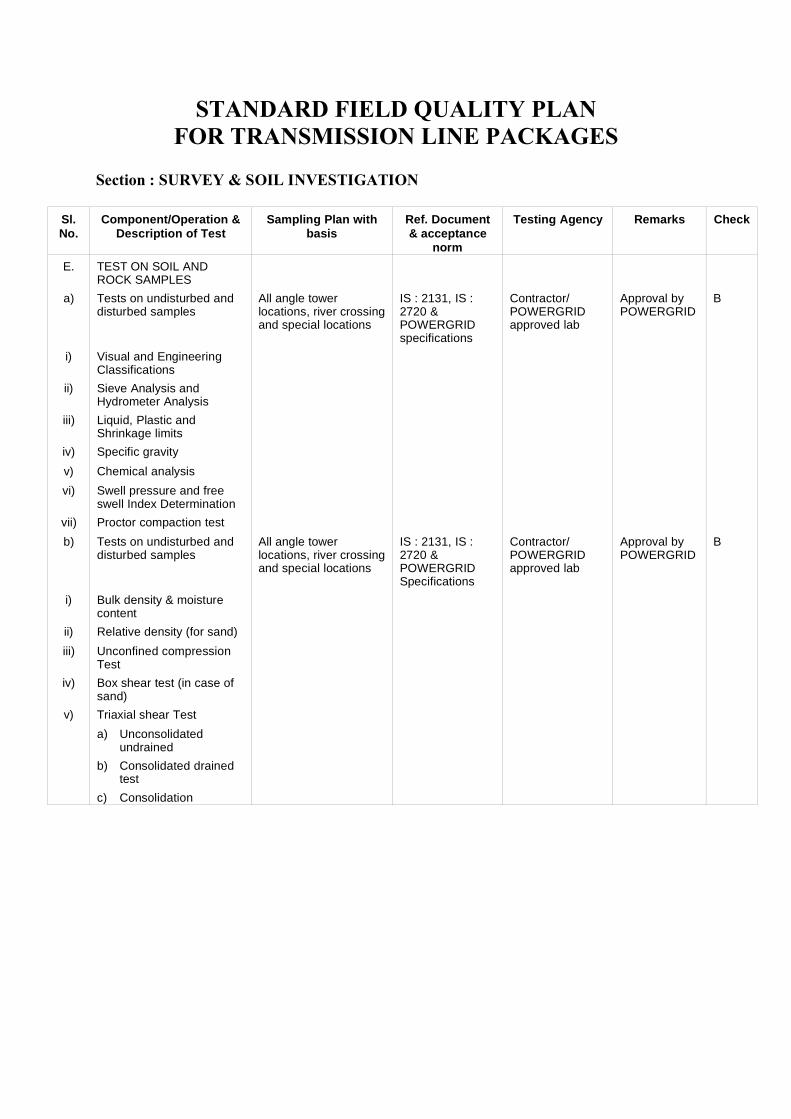
STANDARD FIELD QUALITY PLANFOR TRANSMISSION LINE PACKAGES
Section : SURVEY & SOIL INVESTIGATION
Sl.No.
Component/Operation &Description of Test
Sampling Plan withbasis
Ref. Document& acceptance
norm
Testing Agency Remarks Check
E. TEST ON SOIL ANDROCK SAMPLES
a) Tests on undisturbed anddisturbed samples
All angle towerlocations, river crossingand special locations
IS : 2131, IS :2720 &POWERGRIDspecifications
Contractor/POWERGRIDapproved lab
Approval byPOWERGRID
B
i) Visual and EngineeringClassifications
ii) Sieve Analysis andHydrometer Analysis
iii) Liquid, Plastic andShrinkage limits
iv) Specific gravity
v) Chemical analysis
vi) Swell pressure and freeswell Index Determination
vii) Proctor compaction test
b) Tests on undisturbed anddisturbed samples
All angle towerlocations, river crossingand special locations
IS : 2131, IS :2720 &POWERGRIDSpecifications
Contractor/POWERGRIDapproved lab
Approval by POWERGRID
B
i) Bulk density & moisturecontent
ii) Relative density (for sand)
iii) Unconfined compressionTest
iv) Box shear test (in case ofsand)
v) Triaxial shear Test
a) Unconsolidatedundrained
b) Consolidated drainedtest
c) Consolidation
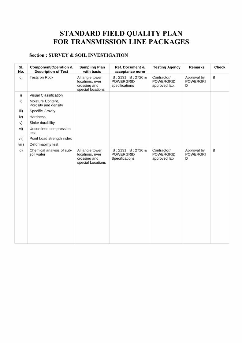
STANDARD FIELD QUALITY PLANFOR TRANSMISSION LINE PACKAGES
Section : SURVEY & SOIL INVESTIGATION
Sl.No.
Component/Operation &Description of Test
Sampling Planwith basis
Ref. Document &acceptance norm
Testing Agency Remarks Check
c) Tests on Rock All angle towerlocations, rivercrossing andspecial locations
IS : 2131, IS : 2720 &POWERGRIDspecifications
Contractor/POWERGRIDapproved lab.
Approval byPOWERGRID
B
i) Visual Classification
ii) Moisture Content,Porosity and density
iii) Specific Gravity
iv) Hardness
v) Slake durability
vi) Unconfined compressiontest
vii) Point Load strength index
viii) Deformability test
d) Chemical analysis of sub-soil water
All angle towerlocations, rivercrossing andspecial Locations
IS : 2131, IS : 2720 & POWERGRIDSpecifications
Contractor/POWERGRIDapproved lab
Approval byPOWERGRID
B
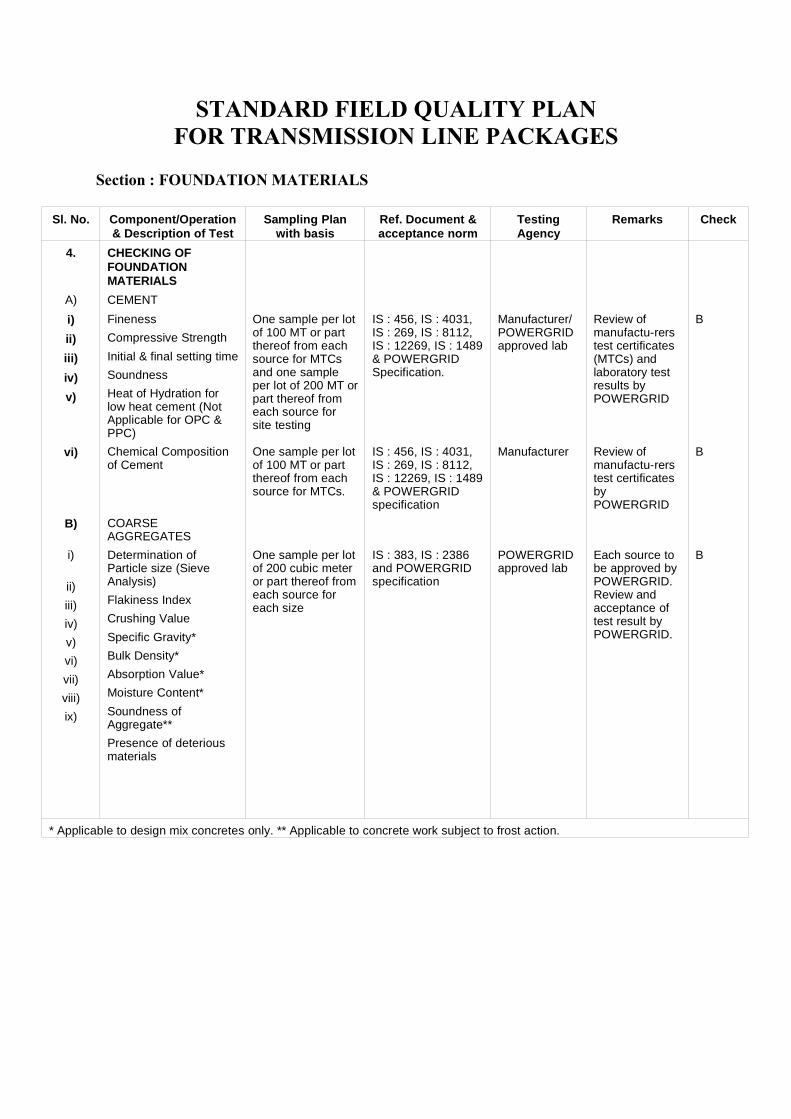
STANDARD FIELD QUALITY PLANFOR TRANSMISSION LINE PACKAGES
Section : FOUNDATION MATERIALS
Sl. No. Component/Operation& Description of Test
Sampling Planwith basis
Ref. Document &acceptance norm
TestingAgency
Remarks Check
4. CHECKING OFFOUNDATIONMATERIALS
A) CEMENT
i)
ii)
iii)
iv)
v)
Fineness
Compressive Strength
Initial & final setting time
Soundness
Heat of Hydration forlow heat cement (NotApplicable for OPC &PPC)
One sample per lotof 100 MT or partthereof from eachsource for MTCsand one sampleper lot of 200 MT orpart thereof fromeach source forsite testing
IS : 456, IS : 4031,IS : 269, IS : 8112,IS : 12269, IS : 1489& POWERGRIDSpecification.
Manufacturer/POWERGRIDapproved lab
Review ofmanufactu-rerstest certificates(MTCs) andlaboratory testresults byPOWERGRID
B
vi) Chemical Compositionof Cement
One sample per lotof 100 MT or partthereof from eachsource for MTCs.
IS : 456, IS : 4031,IS : 269, IS : 8112,IS : 12269, IS : 1489& POWERGRIDspecification
Manufacturer Review ofmanufactu-rerstest certificatesbyPOWERGRID
B
B) COARSEAGGREGATES
i)
ii)
iii)
iv)
v)
vi)
vii)
viii)
ix)
Determination ofParticle size (SieveAnalysis)
Flakiness Index
Crushing Value
Specific Gravity*
Bulk Density*
Absorption Value*
Moisture Content*
Soundness ofAggregate**
Presence of deteriousmaterials
One sample per lotof 200 cubic meteror part thereof fromeach source foreach size
IS : 383, IS : 2386and POWERGRIDspecification
POWERGRIDapproved lab
Each source tobe approved byPOWERGRID.Review andacceptance oftest result byPOWERGRID.
B
* Applicable to design mix concretes only. ** Applicable to concrete work subject to frost action.
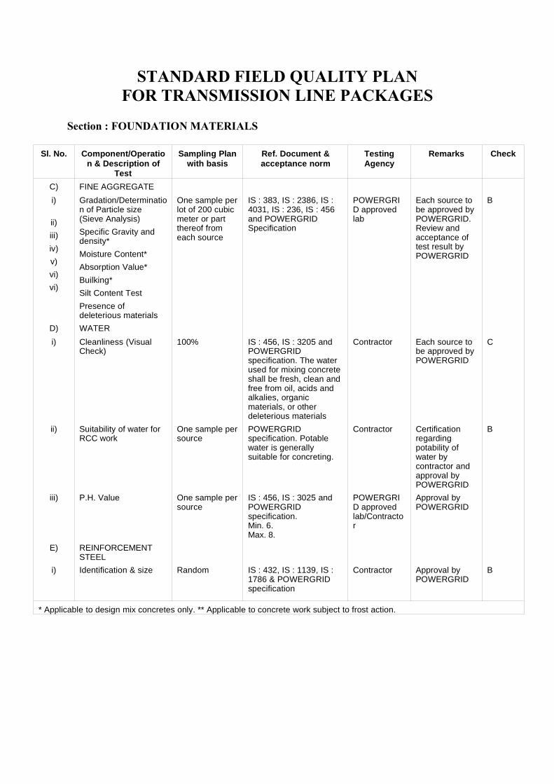
STANDARD FIELD QUALITY PLANFOR TRANSMISSION LINE PACKAGES
Section : FOUNDATION MATERIALS
Sl. No. Component/Operation & Description of
Test
Sampling Planwith basis
Ref. Document &acceptance norm
TestingAgency
Remarks Check
C) FINE AGGREGATE
i)
ii)
iii)
iv)
v)
vi)
vi)
Gradation/Determination of Particle size(Sieve Analysis)
Specific Gravity anddensity*
Moisture Content*
Absorption Value*
Builking*
Silt Content Test
Presence ofdeleterious materials
One sample perlot of 200 cubicmeter or partthereof fromeach source
IS : 383, IS : 2386, IS :4031, IS : 236, IS : 456and POWERGRIDSpecification
POWERGRID approvedlab
Each source tobe approved byPOWERGRID.Review andacceptance oftest result byPOWERGRID
B
D) WATER
i) Cleanliness (VisualCheck)
100% IS : 456, IS : 3205 andPOWERGRIDspecification. The waterused for mixing concreteshall be fresh, clean andfree from oil, acids andalkalies, organicmaterials, or otherdeleterious materials
Contractor Each source tobe approved byPOWERGRID
C
ii) Suitability of water forRCC work
One sample persource
POWERGRIDspecification. Potablewater is generallysuitable for concreting.
Contractor Certificationregardingpotability ofwater bycontractor andapproval byPOWERGRID
B
iii) P.H. Value One sample persource
IS : 456, IS : 3025 andPOWERGRIDspecification.Min. 6.Max. 8.
POWERGRID approvedlab/Contractor
Approval byPOWERGRID
E) REINFORCEMENTSTEEL
i) Identification & size Random IS : 432, IS : 1139, IS :1786 & POWERGRIDspecification
Contractor Approval byPOWERGRID
B
* Applicable to design mix concretes only. ** Applicable to concrete work subject to frost action.
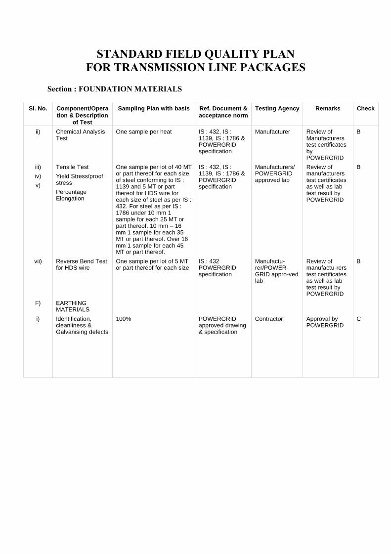
STANDARD FIELD QUALITY PLANFOR TRANSMISSION LINE PACKAGES
Section : FOUNDATION MATERIALS
Sl. No. Component/Operation & Description
of Test
Sampling Plan with basis Ref. Document &acceptance norm
Testing Agency Remarks Check
ii) Chemical AnalysisTest
One sample per heat IS : 432, IS :1139, IS : 1786 &POWERGRIDspecification
Manufacturer Review ofManufacturerstest certificatesbyPOWERGRID
B
iii)
iv)
v)
Tensile Test
Yield Stress/proofstress
PercentageElongation
One sample per lot of 40 MTor part thereof for each sizeof steel conforming to IS :1139 and 5 MT or partthereof for HDS wire foreach size of steel as per IS :432. For steel as per IS :1786 under 10 mm 1sample for each 25 MT orpart thereof. 10 mm – 16mm 1 sample for each 35MT or part thereof. Over 16mm 1 sample for each 45MT or part thereof.
IS : 432, IS :1139, IS : 1786 &POWERGRIDspecification
Manufacturers/POWERGRIDapproved lab
Review ofmanufacturerstest certificatesas well as labtest result byPOWERGRID
B
vii) Reverse Bend Testfor HDS wire
One sample per lot of 5 MTor part thereof for each size
IS : 432POWERGRIDspecification
Manufactu-rer/POWER-GRID appro-vedlab
Review ofmanufactu-rerstest certificatesas well as labtest result byPOWERGRID
B
F) EARTHINGMATERIALS
i) Identification,cleanliness &Galvanising defects
100% POWERGRIDapproved drawing& specification
Contractor Approval byPOWERGRID
C
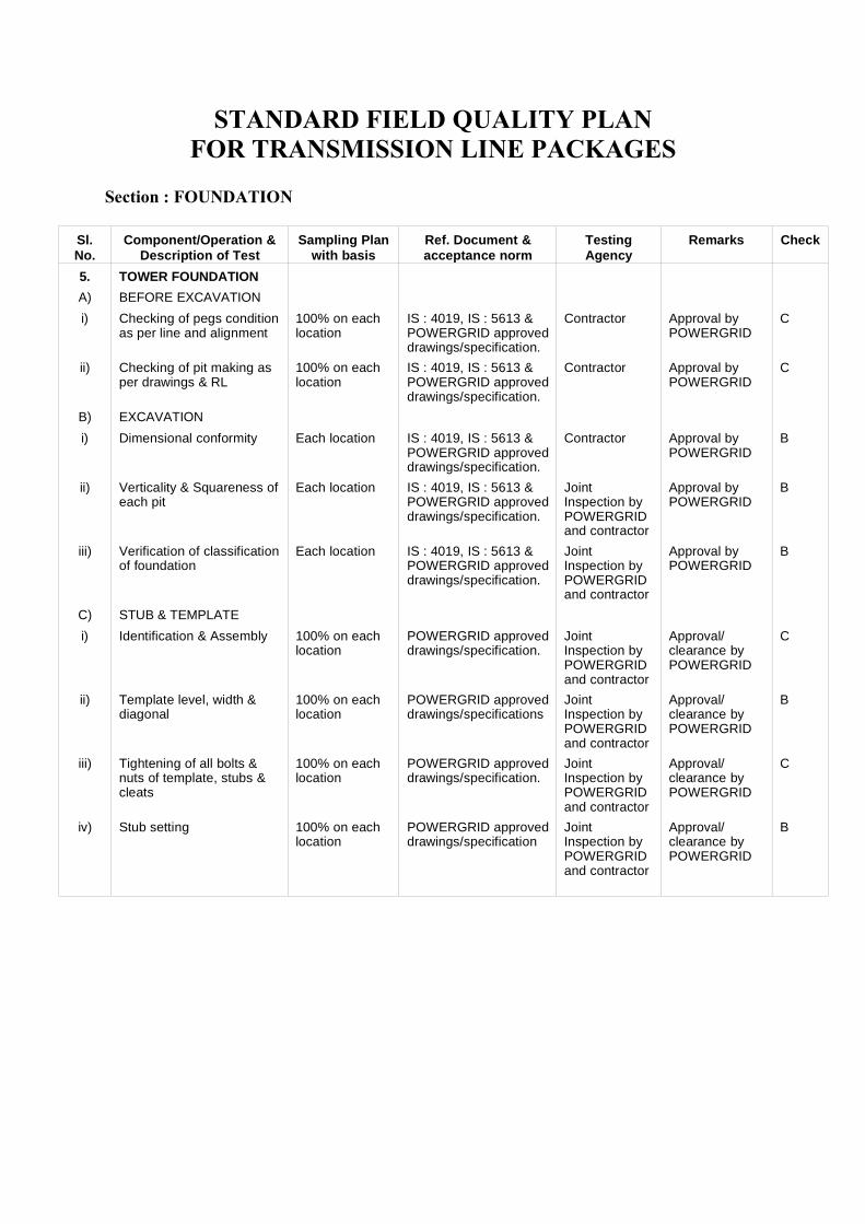
STANDARD FIELD QUALITY PLANFOR TRANSMISSION LINE PACKAGES
Section : FOUNDATION
Sl.No.
Component/Operation &Description of Test
Sampling Planwith basis
Ref. Document &acceptance norm
TestingAgency
Remarks Check
5. TOWER FOUNDATION
A) BEFORE EXCAVATION
i) Checking of pegs conditionas per line and alignment
100% on eachlocation
IS : 4019, IS : 5613 &POWERGRID approveddrawings/specification.
Contractor Approval byPOWERGRID
C
ii) Checking of pit making asper drawings & RL
100% on eachlocation
IS : 4019, IS : 5613 &POWERGRID approveddrawings/specification.
Contractor Approval byPOWERGRID
C
B) EXCAVATION
i) Dimensional conformity Each location IS : 4019, IS : 5613 &POWERGRID approveddrawings/specification.
Contractor Approval byPOWERGRID
B
ii) Verticality & Squareness ofeach pit
Each location IS : 4019, IS : 5613 &POWERGRID approveddrawings/specification.
JointInspection byPOWERGRIDand contractor
Approval byPOWERGRID
B
iii) Verification of classificationof foundation
Each location IS : 4019, IS : 5613 &POWERGRID approveddrawings/specification.
JointInspection byPOWERGRIDand contractor
Approval byPOWERGRID
B
C) STUB & TEMPLATE
i) Identification & Assembly 100% on eachlocation
POWERGRID approveddrawings/specification.
JointInspection byPOWERGRIDand contractor
Approval/clearance byPOWERGRID
C
ii) Template level, width &diagonal
100% on eachlocation
POWERGRID approveddrawings/specifications
JointInspection byPOWERGRIDand contractor
Approval/clearance byPOWERGRID
B
iii) Tightening of all bolts &nuts of template, stubs &cleats
100% on eachlocation
POWERGRID approveddrawings/specification.
JointInspection byPOWERGRIDand contractor
Approval/clearance byPOWERGRID
C
iv) Stub setting 100% on eachlocation
POWERGRID approveddrawings/specification
JointInspection byPOWERGRIDand contractor
Approval/clearance byPOWERGRID
B
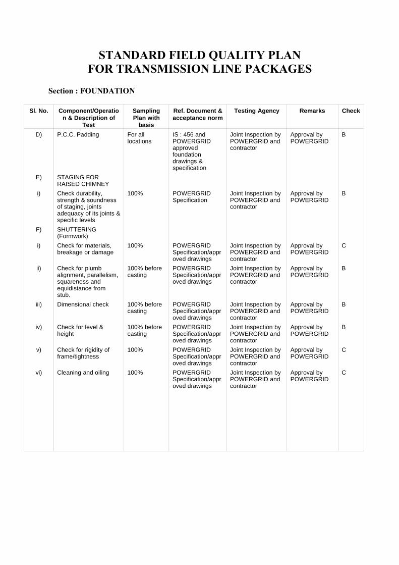
STANDARD FIELD QUALITY PLANFOR TRANSMISSION LINE PACKAGES
Section : FOUNDATION
Sl. No. Component/Operation & Description of
Test
SamplingPlan with
basis
Ref. Document &acceptance norm
Testing Agency Remarks Check
D) P.C.C. Padding For alllocations
IS : 456 andPOWERGRIDapprovedfoundationdrawings &specification
Joint Inspection byPOWERGRID andcontractor
Approval byPOWERGRID
B
E) STAGING FORRAISED CHIMNEY
i) Check durability,strength & soundnessof staging, jointsadequacy of its joints &specific levels
100% POWERGRIDSpecification
Joint Inspection byPOWERGRID andcontractor
Approval byPOWERGRID
B
F) SHUTTERING(Formwork)
i) Check for materials,breakage or damage
100% POWERGRIDSpecification/approved drawings
Joint Inspection byPOWERGRID andcontractor
Approval byPOWERGRID
C
ii) Check for plumbalignment, parallelism,squareness andequidistance fromstub.
100% beforecasting
POWERGRIDSpecification/approved drawings
Joint Inspection byPOWERGRID andcontractor
Approval byPOWERGRID
B
iii) Dimensional check 100% beforecasting
POWERGRIDSpecification/approved drawings
Joint Inspection byPOWERGRID andcontractor
Approval byPOWERGRID
B
iv) Check for level &height
100% beforecasting
POWERGRIDSpecification/approved drawings
Joint Inspection byPOWERGRID andcontractor
Approval byPOWERGRID
B
v) Check for rigidity offrame/tightness
100% POWERGRIDSpecification/approved drawings
Joint Inspection byPOWERGRID andcontractor
Approval byPOWERGRID
C
vi) Cleaning and oiling 100% POWERGRIDSpecification/approved drawings
Joint Inspection byPOWERGRID andcontractor
Approval byPOWERGRID
C
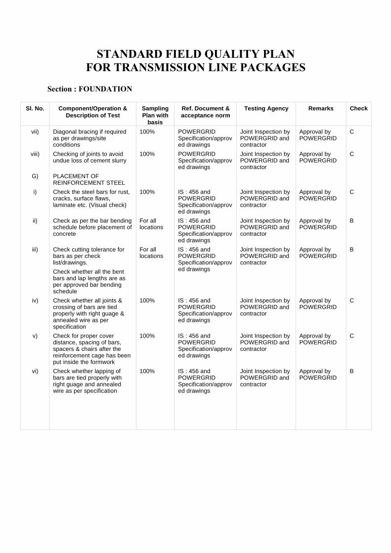
STANDARD FIELD QUALITY PLANFOR TRANSMISSION LINE PACKAGES
Section : FOUNDATION
Sl. No. Component/Operation &Description of Test
SamplingPlan with
basis
Ref. Document &acceptance norm
Testing Agency Remarks Check
vii) Diagonal bracing if requiredas per drawings/siteconditions
100% POWERGRIDSpecification/approved drawings
Joint Inspection byPOWERGRID andcontractor
Approval byPOWERGRID
C
viii) Checking of joints to avoidundue loss of cement slurry
100% POWERGRIDSpecification/approved drawings
Joint Inspection byPOWERGRID andcontractor
Approval byPOWERGRID
C
G) PLACEMENT OFREINFORCEMENT STEEL
i) Check the steel bars for rust,cracks, surface flaws,laminate etc. (Visual check)
100% IS : 456 andPOWERGRIDSpecification/approved drawings
Joint Inspection byPOWERGRID andcontractor
Approval byPOWERGRID
C
ii) Check as per the bar bendingschedule before placement ofconcrete
For alllocations
IS : 456 andPOWERGRIDSpecification/approved drawings
Joint Inspection byPOWERGRID andcontractor
Approval byPOWERGRID
B
iii) Check cutting tolerance forbars as per checklist/drawings.
Check whether all the bentbars and lap lengths are asper approved bar bendingschedule
For alllocations
IS : 456 andPOWERGRIDSpecification/approved drawings
Joint Inspection byPOWERGRID andcontractor
Approval byPOWERGRID
B
iv) Check whether all joints &crossing of bars are tiedproperly with right guage &annealed wire as perspecification
100% IS : 456 andPOWERGRIDSpecification/approved drawings
Joint Inspection byPOWERGRID andcontractor
Approval byPOWERGRID
C
v) Check for proper coverdistance, spacing of bars,spacers & chairs after thereinforcement cage has beenput inside the formwork
100% IS : 456 andPOWERGRIDSpecification/approved drawings
Joint Inspection byPOWERGRID andcontractor
Approval byPOWERGRID
C
vi) Check whether lapping ofbars are tied properly withright guage and annealedwire as per specification
100% IS : 456 andPOWERGRIDSpecification/approved drawings
Joint Inspection byPOWERGRID andcontractor
Approval byPOWERGRID
B
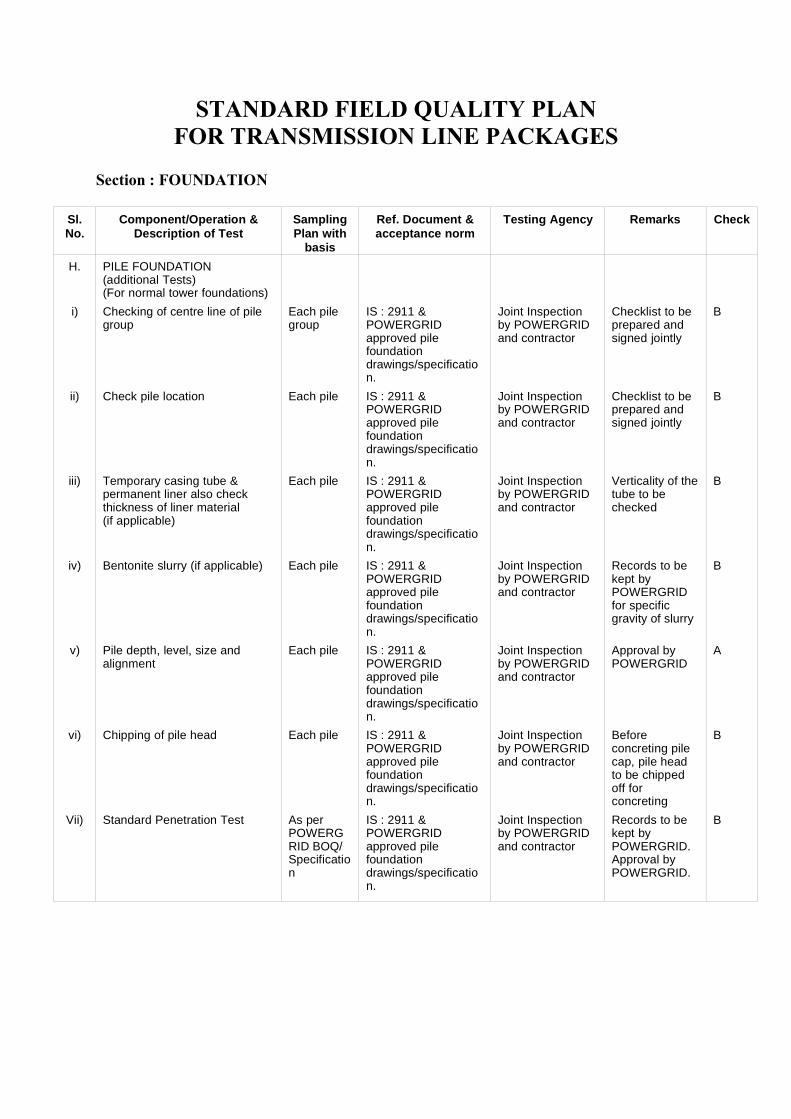
STANDARD FIELD QUALITY PLANFOR TRANSMISSION LINE PACKAGES
Section : FOUNDATION
Sl.No.
Component/Operation &Description of Test
SamplingPlan with
basis
Ref. Document &acceptance norm
Testing Agency Remarks Check
H. PILE FOUNDATION (additional Tests)(For normal tower foundations)
i) Checking of centre line of pilegroup
Each pilegroup
IS : 2911 &POWERGRIDapproved pilefoundationdrawings/specification.
Joint Inspectionby POWERGRIDand contractor
Checklist to beprepared andsigned jointly
B
ii) Check pile location Each pile IS : 2911 &POWERGRIDapproved pilefoundationdrawings/specification.
Joint Inspectionby POWERGRIDand contractor
Checklist to beprepared andsigned jointly
B
iii) Temporary casing tube &permanent liner also checkthickness of liner material (if applicable)
Each pile IS : 2911 &POWERGRIDapproved pilefoundationdrawings/specification.
Joint Inspectionby POWERGRIDand contractor
Verticality of thetube to bechecked
B
iv) Bentonite slurry (if applicable) Each pile IS : 2911 &POWERGRIDapproved pilefoundationdrawings/specification.
Joint Inspectionby POWERGRIDand contractor
Records to bekept byPOWERGRIDfor specificgravity of slurry
B
v) Pile depth, level, size andalignment
Each pile IS : 2911 &POWERGRIDapproved pilefoundationdrawings/specification.
Joint Inspectionby POWERGRIDand contractor
Approval byPOWERGRID
A
vi) Chipping of pile head Each pile IS : 2911 &POWERGRIDapproved pilefoundationdrawings/specification.
Joint Inspectionby POWERGRIDand contractor
Beforeconcreting pilecap, pile headto be chippedoff forconcreting
B
Vii) Standard Penetration Test As perPOWERGRID BOQ/Specification
IS : 2911 &POWERGRIDapproved pilefoundationdrawings/specification.
Joint Inspectionby POWERGRIDand contractor
Records to bekept byPOWERGRID.Approval byPOWERGRID.
B
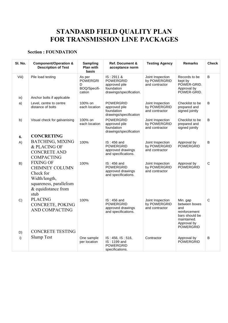
STANDARD FIELD QUALITY PLANFOR TRANSMISSION LINE PACKAGES
Section : FOUNDATION
Sl. No. Component/Operation &Description of Test
SamplingPlan with
basis
Ref. Document &acceptance norm
Testing Agency Remarks Check
Viii) Pile load testing As perPOWERGRIDBOQ/Specifi-cation
IS : 2911 &POWERGRIDapproved pilefoundationdrawings/specification.
Joint Inspectionby POWERGRIDand contractor
Records to bekept byPOWER-GRID.Approval byPOWER-GRID.
B
ix) Anchor bolts if applicable
a) Level, centre to centredistance of bolts
100% oneach location
POWERGRIDapproved pilefoundationdrawings/specification
Joint Inspectionby POWERGRIDand contractor
Checklist to beprepared andsigned jointly
B
b) Visual check for galvanising 100% oneach location
POWERGRIDapproved pilefoundationdrawings/specification
Joint Inspectionby POWERGRIDand contractor
Checklist to beprepared andsigned jointly
B
6. CONCRETINGA) BATCHING, MIXING
& PLACING OFCONCRETE ANDCOMPACTING
100% IS : 456 andPOWERGRIDapproved drawingsand specifications.
Joint Inspectionby POWERGRIDand contractor
Approval byPOWERGRID
B
B) FIXING OFCHIMNEY COLUMNCheck forWidth/length,squareness, parallelism& equidistance fromstub
100% IS : 456 andPOWERGRIDapproved drawingsand specifications.
Joint Inspectionby POWERGRIDand contractor
Approval byPOWERGRID
C
C) PLACINGCONCRETE, POKINGAND COMPACTING
100% IS : 456 andPOWERGRIDapproved drawingsand specifications.
Joint Inspectionby POWERGRIDand contractor
Min. gapbetween boxesandreinforcementbars should bemaintained.Approval byPOWERGRID
C
D) CONCRETE TESTINGi) Slump Test One sample
per locationIS : 456, IS : 516, IS : 1199 andPOWERGRIDspecifications.
Contractor Approval byPOWERGRID
B
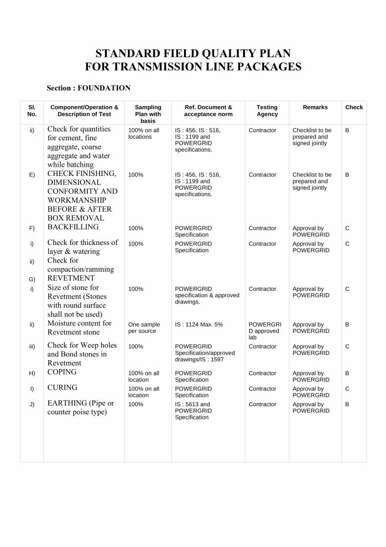
STANDARD FIELD QUALITY PLANFOR TRANSMISSION LINE PACKAGES
Section : FOUNDATION
Sl.No.
Component/Operation &Description of Test
SamplingPlan with
basis
Ref. Document &acceptance norm
TestingAgency
Remarks Check
ii) Check for quantitiesfor cement, fineaggregate, coarseaggregate and waterwhile batching
100% on alllocations
IS : 456, IS : 516, IS : 1199 andPOWERGRIDspecifications.
Contractor Checklist to beprepared andsigned jointly
B
E) CHECK FINISHING,DIMENSIONALCONFORMITY ANDWORKMANSHIPBEFORE & AFTERBOX REMOVAL
100% IS : 456, IS : 516, IS : 1199 andPOWERGRIDspecifications.
Contractor Checklist to beprepared andsigned jointly
B
F) BACKFILLING 100% POWERGRIDSpecification
Contractor Approval byPOWERGRID
C
i) Check for thickness oflayer & watering
100% POWERGRIDSpecification
Contractor Approval byPOWERGRID
C
ii) Check forcompaction/ramming
G) REVETMENTi) Size of stone for
Revetment (Stoneswith round surfaceshall not be used)
100% POWERGRIDspecification & approveddrawings.
Contractor Approval byPOWERGRID
C
ii) Moisture content forRevetment stone
One sampleper source
IS : 1124 Max. 5% POWERGRID approvedlab
Approval byPOWERGRID
B
iii) Check for Weep holesand Bond stones inRevetment
100% POWERGRIDSpecification/approveddrawings/IS : 1597
Contractor Approval byPOWERGRID
C
H) COPING 100% on alllocation
POWERGRIDSpecification
Contractor Approval byPOWERGRID
B
I) CURING 100% on alllocation
POWERGRIDSpecification
Contractor Approval byPOWERGRID
C
J) EARTHING (Pipe orcounter poise type)
100% IS : 5613 andPOWERGRIDSpecification
Contractor Approval byPOWERGRID
B

STANDARD FIELD QUALITY PLANFOR TRANSMISSION LINE PACKAGES
Section : FOUNDATION
Sl. No. Component/Operation & Description of
Test
Sampling Plan withbasis
Ref. Document &acceptance norm
TestingAgency
Remarks Check
K) CONCRETECUBE TESTING
i) CompressiveStrength
a) One samplelocations (Onesample consists ofmin. 3 test cubes for28 days strength)
b) For pilefoundation onesample for each pile
IS : 1199, IS : 456, IS : 516 andPOWERGRIDSpecification
POWERGRIDapproved lab
Approval byPOWERGRIDCubes must betested within aweek after 28days curingperiod and testresults shouldbe approvedbefore towererection
A
ii) CompressiveStrength forconcrete of pilecap, beams,chimney etc.
One sample forevery 20 Cum ofconcrete or partthereof for eachdays of concreting
IS : 1199, IS : 456, IS : 516 andPOWERGRIDSpecification
POWERGRIDapproved lab
-do- A
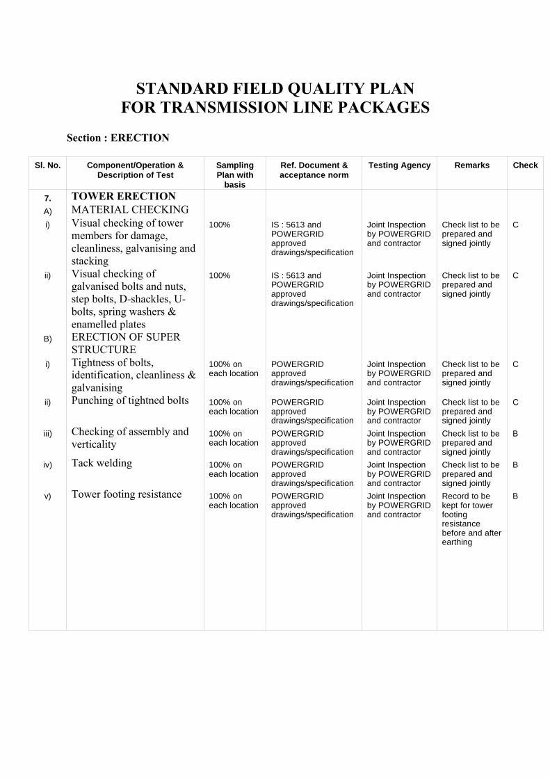
STANDARD FIELD QUALITY PLANFOR TRANSMISSION LINE PACKAGES
Section : ERECTION
Sl. No. Component/Operation &Description of Test
SamplingPlan with
basis
Ref. Document &acceptance norm
Testing Agency Remarks Check
7. TOWER ERECTIONA) MATERIAL CHECKINGi) Visual checking of tower
members for damage,cleanliness, galvanising andstacking
100% IS : 5613 andPOWERGRIDapproveddrawings/specification
Joint Inspectionby POWERGRIDand contractor
Check list to beprepared andsigned jointly
C
ii) Visual checking ofgalvanised bolts and nuts,step bolts, D-shackles, U-bolts, spring washers &enamelled plates
100% IS : 5613 andPOWERGRIDapproveddrawings/specification
Joint Inspectionby POWERGRIDand contractor
Check list to beprepared andsigned jointly
C
B) ERECTION OF SUPERSTRUCTURE
i) Tightness of bolts,identification, cleanliness &galvanising
100% oneach location
POWERGRIDapproveddrawings/specification
Joint Inspectionby POWERGRIDand contractor
Check list to beprepared andsigned jointly
C
ii) Punching of tightned bolts 100% oneach location
POWERGRIDapproveddrawings/specification
Joint Inspectionby POWERGRIDand contractor
Check list to beprepared andsigned jointly
C
iii) Checking of assembly andverticality
100% oneach location
POWERGRIDapproveddrawings/specification
Joint Inspectionby POWERGRIDand contractor
Check list to beprepared andsigned jointly
B
iv) Tack welding 100% oneach location
POWERGRIDapproveddrawings/specification
Joint Inspectionby POWERGRIDand contractor
Check list to beprepared andsigned jointly
B
v) Tower footing resistance 100% oneach location
POWERGRIDapproveddrawings/specification
Joint Inspectionby POWERGRIDand contractor
Record to bekept for towerfootingresistancebefore and afterearthing
B
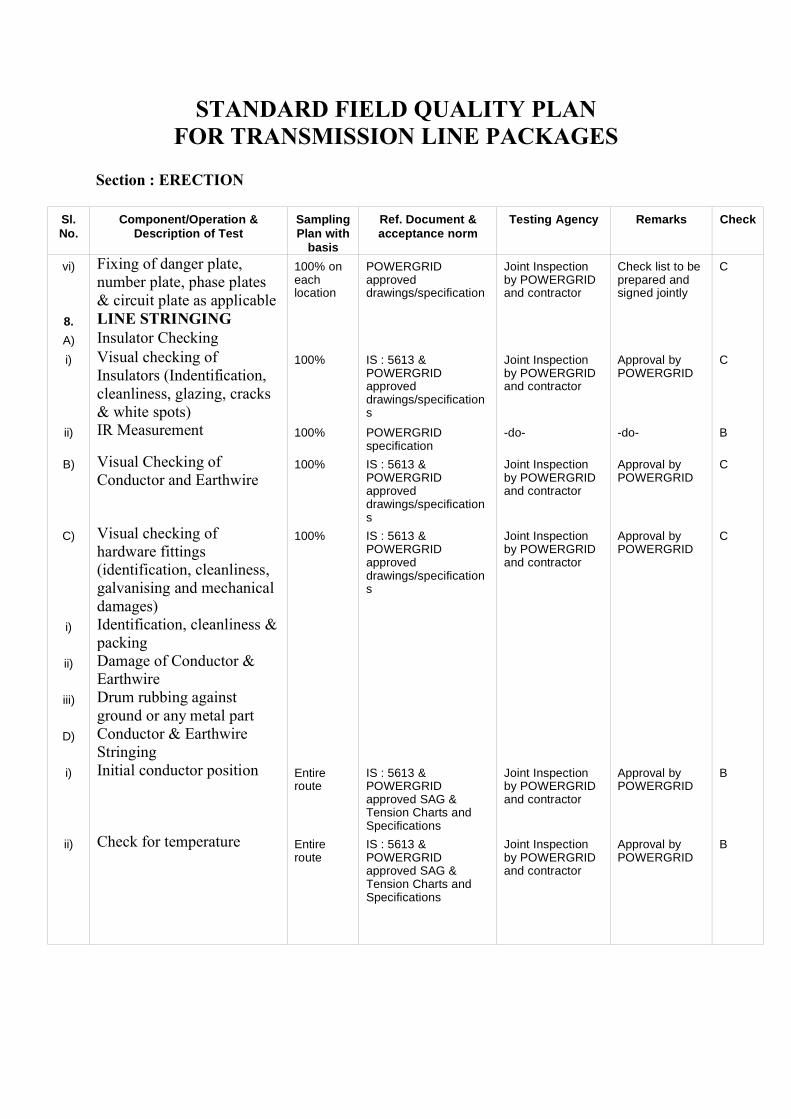
STANDARD FIELD QUALITY PLANFOR TRANSMISSION LINE PACKAGES
Section : ERECTION
Sl.No.
Component/Operation &Description of Test
SamplingPlan with
basis
Ref. Document &acceptance norm
Testing Agency Remarks Check
vi) Fixing of danger plate,number plate, phase plates& circuit plate as applicable
100% oneachlocation
POWERGRIDapproveddrawings/specification
Joint Inspectionby POWERGRIDand contractor
Check list to beprepared andsigned jointly
C
8. LINE STRINGINGA) Insulator Checkingi) Visual checking of
Insulators (Indentification,cleanliness, glazing, cracks& white spots)
100% IS : 5613 &POWERGRIDapproveddrawings/specifications
Joint Inspectionby POWERGRIDand contractor
Approval byPOWERGRID
C
ii) IR Measurement 100% POWERGRIDspecification
-do- -do- B
B) Visual Checking ofConductor and Earthwire
100% IS : 5613 &POWERGRIDapproveddrawings/specifications
Joint Inspectionby POWERGRIDand contractor
Approval byPOWERGRID
C
C) Visual checking ofhardware fittings(identification, cleanliness,galvanising and mechanicaldamages)
100% IS : 5613 &POWERGRIDapproveddrawings/specifications
Joint Inspectionby POWERGRIDand contractor
Approval byPOWERGRID
C
i) Identification, cleanliness &packing
ii) Damage of Conductor &Earthwire
iii) Drum rubbing againstground or any metal part
D) Conductor & EarthwireStringing
i) Initial conductor position Entireroute
IS : 5613 &POWERGRIDapproved SAG &Tension Charts andSpecifications
Joint Inspectionby POWERGRIDand contractor
Approval byPOWERGRID
B
ii) Check for temperature Entireroute
IS : 5613 &POWERGRIDapproved SAG &Tension Charts andSpecifications
Joint Inspectionby POWERGRIDand contractor
Approval byPOWERGRID
B
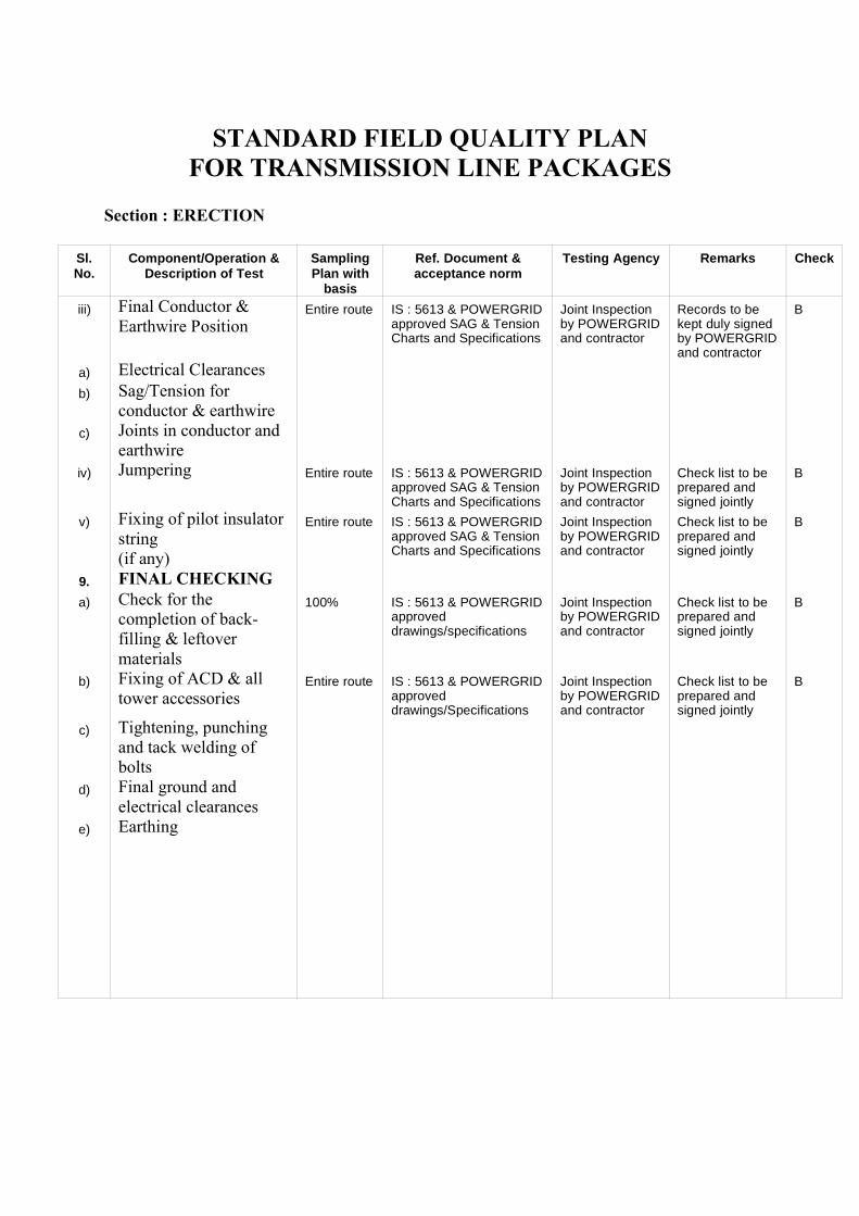
STANDARD FIELD QUALITY PLANFOR TRANSMISSION LINE PACKAGES
Section : ERECTION
Sl.No.
Component/Operation &Description of Test
SamplingPlan with
basis
Ref. Document &acceptance norm
Testing Agency Remarks Check
iii) Final Conductor &Earthwire Position
Entire route IS : 5613 & POWERGRIDapproved SAG & TensionCharts and Specifications
Joint Inspectionby POWERGRIDand contractor
Records to bekept duly signedby POWERGRIDand contractor
B
a) Electrical Clearancesb) Sag/Tension for
conductor & earthwirec) Joints in conductor and
earthwireiv) Jumpering Entire route IS : 5613 & POWERGRID
approved SAG & TensionCharts and Specifications
Joint Inspectionby POWERGRIDand contractor
Check list to beprepared andsigned jointly
B
v) Fixing of pilot insulatorstring (if any)
Entire route IS : 5613 & POWERGRIDapproved SAG & TensionCharts and Specifications
Joint Inspectionby POWERGRIDand contractor
Check list to beprepared andsigned jointly
B
9. FINAL CHECKINGa) Check for the
completion of back-filling & leftovermaterials
100% IS : 5613 & POWERGRIDapproveddrawings/specifications
Joint Inspectionby POWERGRIDand contractor
Check list to beprepared andsigned jointly
B
b) Fixing of ACD & alltower accessories
Entire route IS : 5613 & POWERGRIDapproveddrawings/Specifications
Joint Inspectionby POWERGRIDand contractor
Check list to beprepared andsigned jointly
B
c) Tightening, punchingand tack welding ofbolts
d) Final ground andelectrical clearances
e) Earthing

STANDARD FIELD QUALITY PLANFOR TRANSMISSION LINE PACKAGES
Section : FINAL TESTING & PRE-COMMISSIONING
Sl. No. Component/Operation &Description of Test
SamplingPlan with
basis
Ref. Document &acceptance norm
Testing Agency Remarks Check
10. MEGGAR TEST 100% POWERGRID latest Pre-Commissioning procedures(Doc. No. D-2-01-70-01-00)
Joint Inspectionby POWERGRIDand contractor
Records to bekept duly signedby POWERGRIDand contractor
A
11. FINALTESTING &PRE-COMMISSIONING ON LINE
100% POWERGRID latest Pre-CommissioningProcedures (Doc. No. D-2-01-70-0-00)
Joint Inspectionby POWERGRIDand contractor
Records to bekept duly signedby POWERGRIDand contractor
A
Section : GENERAL GUIDELINES FOR IMPLEMENTATION
1. Details of categories of check codes A, B & C including accepting anddeviation dispositioning authorities are indicated at Annexure-I.
2. POWERGRID specification shall mean POWERGRID technicalspecification, approved drawings/data sheets and LOA provisionsapplicable for the specific contract.
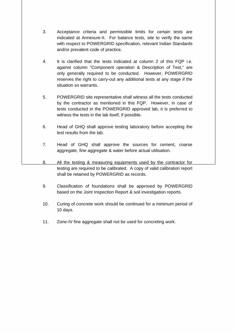
3. Acceptance criteria and permissible limits for certain tests areindicated at Annexure-II. For balance tests, site to verify the samewith respect to POWERGRID specification, relevant Indian Standardsand/or prevalent code of practice.
4. It is clarified that the tests indicated at column 2 of this FQP i.e.against column "Component operation & Description of Test," areonly generally required to be conducted. However, POWERGRIDreserves the right to carry-out any additional tests at any stage if thesituation so warrants.
5. POWERGRID site representative shall witness all the tests conductedby the contractor as mentioned in this FQP. However, in case oftests conducted in the POWERGRID approved lab, it is preferred towitness the tests in the lab itself, if possible.
6. Head of GHQ shall approve testing laboratory before accepting thetest results from the lab.
7. Head of GHQ shall approve the sources for cement, coarseaggregate, fine aggregate & water before actual utilisation.
8. All the testing & measuring equipments used by the contractor fortesting are required to be calibrated. A copy of valid calibration reportshall be retained by POWERGRID as records.
9. Classification of foundations shall be approved by POWERGRIDbased on the Joint Inspection Report & soil investigation reports.
10. Curing of concrete work should be continued for a minimum period of10 days.
11. Zone-IV fine aggregate shall not be used for concreting work.
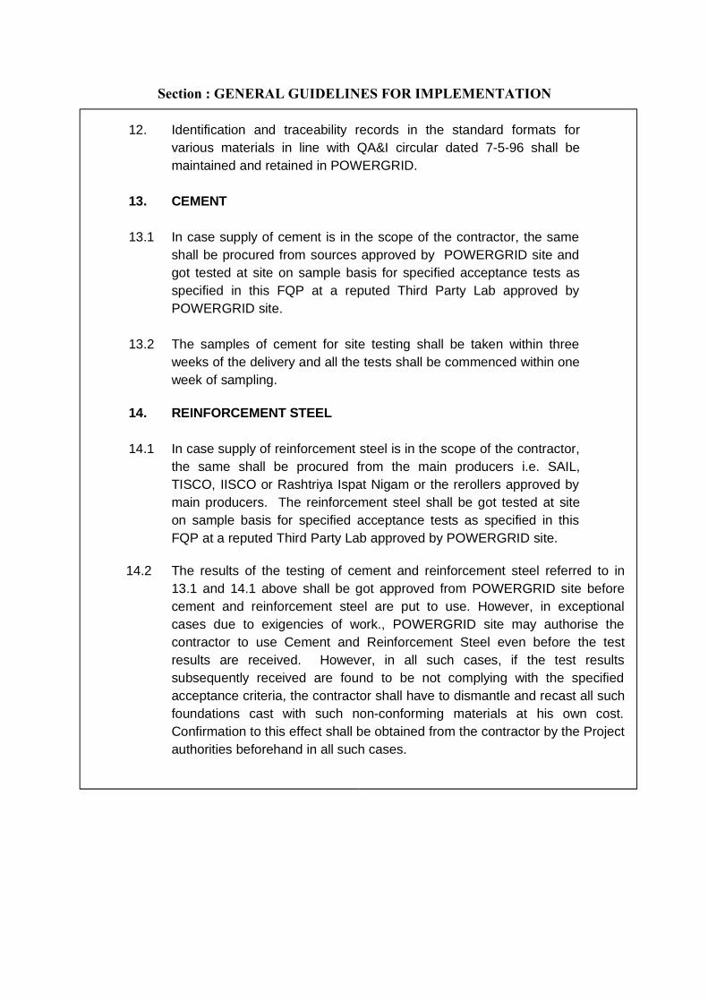
Section : GENERAL GUIDELINES FOR IMPLEMENTATION
12. Identification and traceability records in the standard formats forvarious materials in line with QA&I circular dated 7-5-96 shall bemaintained and retained in POWERGRID.
13. CEMENT
13.1 In case supply of cement is in the scope of the contractor, the sameshall be procured from sources approved by POWERGRID site andgot tested at site on sample basis for specified acceptance tests asspecified in this FQP at a reputed Third Party Lab approved byPOWERGRID site.
13.2 The samples of cement for site testing shall be taken within threeweeks of the delivery and all the tests shall be commenced within oneweek of sampling.
14. REINFORCEMENT STEEL
14.1 In case supply of reinforcement steel is in the scope of the contractor,the same shall be procured from the main producers i.e. SAIL,TISCO, IISCO or Rashtriya Ispat Nigam or the rerollers approved bymain producers. The reinforcement steel shall be got tested at siteon sample basis for specified acceptance tests as specified in thisFQP at a reputed Third Party Lab approved by POWERGRID site.
14.2 The results of the testing of cement and reinforcement steel referred to in13.1 and 14.1 above shall be got approved from POWERGRID site beforecement and reinforcement steel are put to use. However, in exceptionalcases due to exigencies of work., POWERGRID site may authorise thecontractor to use Cement and Reinforcement Steel even before the testresults are received. However, in all such cases, if the test resultssubsequently received are found to be not complying with the specifiedacceptance criteria, the contractor shall have to dismantle and recast all suchfoundations cast with such non-conforming materials at his own cost.Confirmation to this effect shall be obtained from the contractor by the Projectauthorities beforehand in all such cases.

ANNEXURE-IPAGE 1 OF 1
ACCEPTING AND DEVIATION DISPOSITIONING AUTHORITIES FORDIFFERENT CATEGORIES
OF CHECKS AS ENVISAGED IN FIELD QUALITY PLAN
CATEGORY TYPE OFCHECK
100% CHECKING/WITNESSING BY
COUNTERCHECK/SURVEILLANCE
CHECK BY
ACCEPTINGAUTHORITY, IF TEST
RESULTS ARE WITHINPERMISSIBLE LIMITS
DEVIATIONDISPOSITIONING
AUTHORITY
A CRITICAL EXECUTING DEPTT.PLUS FQA
REPRESENTATIVEGHQ
FQA REPRESENTATIVEAND RHQ/DHQ
REPRESENTATIVE
HEAD OF DHQ HEAD OF RHQ INCONSULTATION
WITH CQA, IFREQUIRED
B MAJOR EXECUTING DEPTT. DHQ REPRESENTATIVE HEAD OF GHQ HEAD OF DHQC MINOR CONTRACTORS
REPRESENTATIVEEXECUTING DEPTT. MINIMUM E4 LEVEL
EXCUTIVE OF SUB-STATION/TL
HEAD OF GHQ
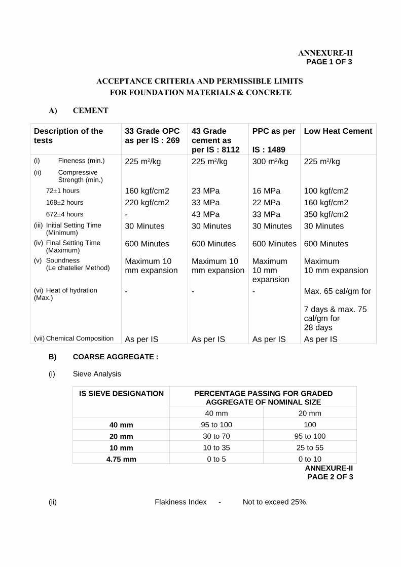
ANNEXURE-IIPAGE 1 OF 3
ACCEPTANCE CRITERIA AND PERMISSIBLE LIMITS FOR FOUNDATION MATERIALS & CONCRETE
A) CEMENT
Description of thetests
33 Grade OPCas per IS : 269
43 Gradecement asper IS : 8112
PPC as per
IS : 1489
Low Heat Cement
(i) Fineness (min.) 225 m2/kg 225 m2/kg 300 m2/kg 225 m2/kg(ii) Compressive
Strength (min.)
721 hours 160 kgf/cm2 23 MPa 16 MPa 100 kgf/cm21682 hours 220 kgf/cm2 33 MPa 22 MPa 160 kgf/cm26724 hours - 43 MPa 33 MPa 350 kgf/cm2
(iii) Initial Setting Time(Minimum)
30 Minutes 30 Minutes 30 Minutes 30 Minutes
(iv) Final Setting Time(Maximum)
600 Minutes 600 Minutes 600 Minutes 600 Minutes
(v) Soundness(Le chatelier Method)
Maximum 10mm expansion
Maximum 10mm expansion
Maximum 10 mmexpansion
Maximum 10 mm expansion
(vi) Heat of hydration (Max.)
- - - Max. 65 cal/gm for
7 days & max. 75cal/gm for 28 days
(vii) Chemical Composition As per IS As per IS As per IS As per IS
B) COARSE AGGREGATE :
(i) Sieve Analysis
IS SIEVE DESIGNATION PERCENTAGE PASSING FOR GRADEDAGGREGATE OF NOMINAL SIZE
40 mm 20 mm
40 mm 95 to 100 100
20 mm 30 to 70 95 to 100
10 mm 10 to 35 25 to 55
4.75 mm 0 to 5 0 to 10ANNEXURE-IIPAGE 2 OF 3
(ii) Flakiness Index - Not to exceed 25%.
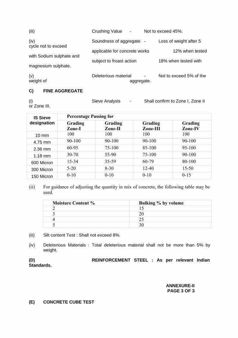
(iii) Crushing Value - Not to exceed 45%.
(iv) Soundness of aggregate - Loss of weight after 5cycle not to exceed
applicable for concrete works 12% when testedwith Sodium sulphate and
subject to froast action 18% when tested withmagnesium sulphate.
(v) Deleterious material - Not to exceed 5% of theweight of aggregate.
C) FINE AGGREGATE
(i) Sieve Analysis - Shall confirm to Zone I, Zone IIor Zone III.
IS Sievedesignation
Percentage Passing forGradingZone-I
GradingZone-II
GradingZone-III
GradingZone-IV
10 mm 100 100 100 100
4.75 mm 90-100 90-100 90-100 90-100
2.36 mm 60-95 75-100 85-100 95-100
1.18 mm 30-70 55-90 75-100 90-100
600 Micron 15-34 35-59 60-79 80-100
300 Micron 5-20 8-30 12-40 15-50
150 Micron 0-10 0-10 0-10 0-15
(ii) For guidance of adjusting the quantity in mix of concrete, the following table may beused.
Moisture Content % Bulking % by volume2 153 204 255 30
(iii) Silt content Test : Shall not exceed 8%.
(iv) Deleterious Materials : Total deleterious material shall not be more than 5% byweight.
(D) REINFORCEMENT STEEL : As per relevant IndianStandards.
ANNEXURE-IIPAGE 3 OF 3
(E) CONCRETE CUBE TEST
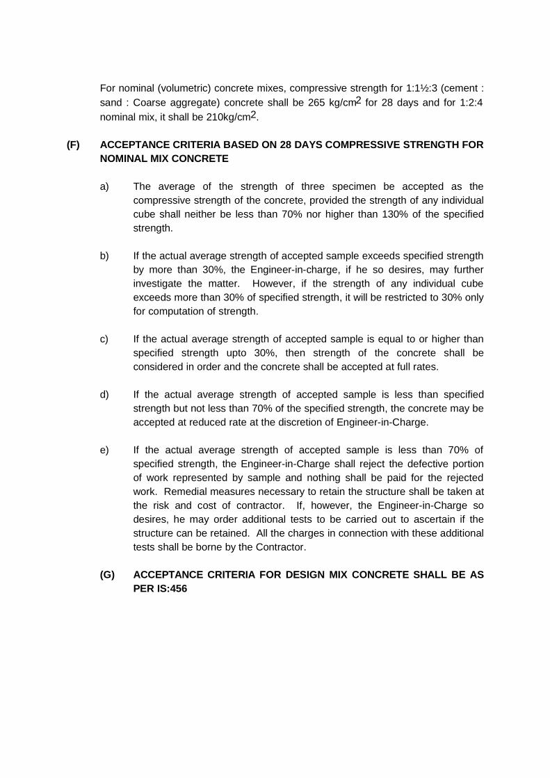
For nominal (volumetric) concrete mixes, compressive strength for 1:1½:3 (cement :sand : Coarse aggregate) concrete shall be 265 kg/cm2 for 28 days and for 1:2:4nominal mix, it shall be 210kg/cm2.
(F) ACCEPTANCE CRITERIA BASED ON 28 DAYS COMPRESSIVE STRENGTH FORNOMINAL MIX CONCRETE
a) The average of the strength of three specimen be accepted as thecompressive strength of the concrete, provided the strength of any individualcube shall neither be less than 70% nor higher than 130% of the specifiedstrength.
b) If the actual average strength of accepted sample exceeds specified strengthby more than 30%, the Engineer-in-charge, if he so desires, may furtherinvestigate the matter. However, if the strength of any individual cubeexceeds more than 30% of specified strength, it will be restricted to 30% onlyfor computation of strength.
c) If the actual average strength of accepted sample is equal to or higher thanspecified strength upto 30%, then strength of the concrete shall beconsidered in order and the concrete shall be accepted at full rates.
d) If the actual average strength of accepted sample is less than specifiedstrength but not less than 70% of the specified strength, the concrete may beaccepted at reduced rate at the discretion of Engineer-in-Charge.
e) If the actual average strength of accepted sample is less than 70% ofspecified strength, the Engineer-in-Charge shall reject the defective portionof work represented by sample and nothing shall be paid for the rejectedwork. Remedial measures necessary to retain the structure shall be taken atthe risk and cost of contractor. If, however, the Engineer-in-Charge sodesires, he may order additional tests to be carried out to ascertain if thestructure can be retained. All the charges in connection with these additionaltests shall be borne by the Contractor.
(G) ACCEPTANCE CRITERIA FOR DESIGN MIX CONCRETE SHALL BE ASPER IS:456
CHAPTER-9
Guidelines
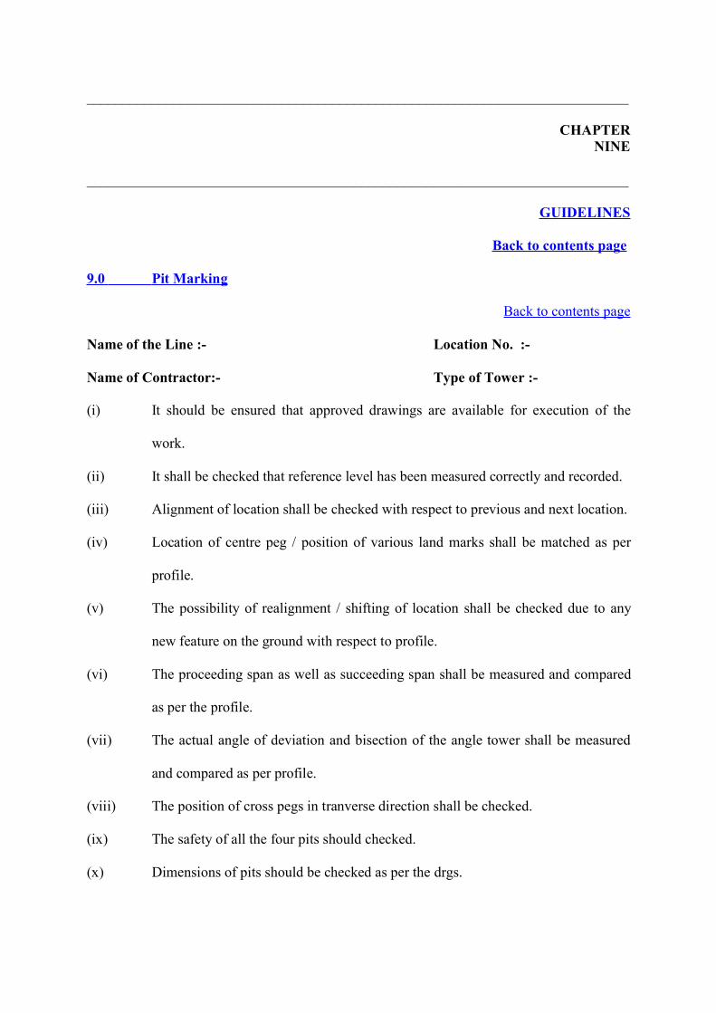
___________________________________________________________________________
CHAPTERNINE
___________________________________________________________________________
GUIDELINES
Back to contents page
9.0 Pit Marking
Back to contents page
Name of the Line :- Location No. :-
Name of Contractor:- Type of Tower :-
(i) It should be ensured that approved drawings are available for execution of the
work.
(ii) It shall be checked that reference level has been measured correctly and recorded.
(iii) Alignment of location shall be checked with respect to previous and next location.
(iv) Location of centre peg / position of various land marks shall be matched as per
profile.
(v) The possibility of realignment / shifting of location shall be checked due to any
new feature on the ground with respect to profile.
(vi) The proceeding span as well as succeeding span shall be measured and compared
as per the profile.
(vii) The actual angle of deviation and bisection of the angle tower shall be measured
and compared as per profile.
(viii) The position of cross pegs in tranverse direction shall be checked.
(ix) The safety of all the four pits should checked.
(x) Dimensions of pits should be checked as per the drgs.

(xi) The requirement of Benching / Revetment shall be examined and contour maps /
Revetment drgs. shall prepared wherever necessary.
(xii) In case of benching, the volume of cutting and filling shall be calculated and
recorded in cu.m. as per the benching drg.
(xiii) In case of Revetment, the volume of Revetment quantity shall be calculated
and recorded as per the Revetment drg.

9 .1 Stub Setting
Name of the Line :- Location No. :-
Name of Contractor:- Type of Tower :-
(i) It should be ensured that the drgs. are approved for the stub setting.
(ii)
a) The depths of all four pits (A, B, C, D) shall be measured and tabulated from Ground
level as well as Reference level.
b) Pit dimensions shall be checked as per approved found, classifn. drg.
c) Excavated soil should be stacked at least 2m away from pit edge to avoid collapse of the
foundation pit.
d) Undercutting of foundation shall be checked as per the drg. in case of fissured rocks.
(iii)
a) Tangent Tower
The alignment of the template in the direction of the line shall be checked in case of
tangent Tower.
b) Angle Tower
(b.a) The Angle of deviation shall be checked as per the drg.
(b.b) The alignment of template on bisection shall be checked.
(iv) Diagonals of template shall be measured with respect to the approved drgs.
Stub Setting on Bisection
(v) The Level of template should be checked by dumpy level.
(vi) Ht. of template above ground level shall be checked.
(vii) The clearance (not less than 15 cm or as specified in the drg.) between lowest part
of all the four stubs and base of the pit shall be checked.

(viii) Positioning of the template support shall be checked with regard to any danger to
the collapse of pit.
(ix) Tightening and erection of the template should be checked as per drg.
(x) Checking of stubs.
(a) The dimensions of the stubs shall be checked as per type of tower.
(b) The proper erection of the plates / cleats with regd. nos of properly tightened bolts
shall be checked as per the drg.
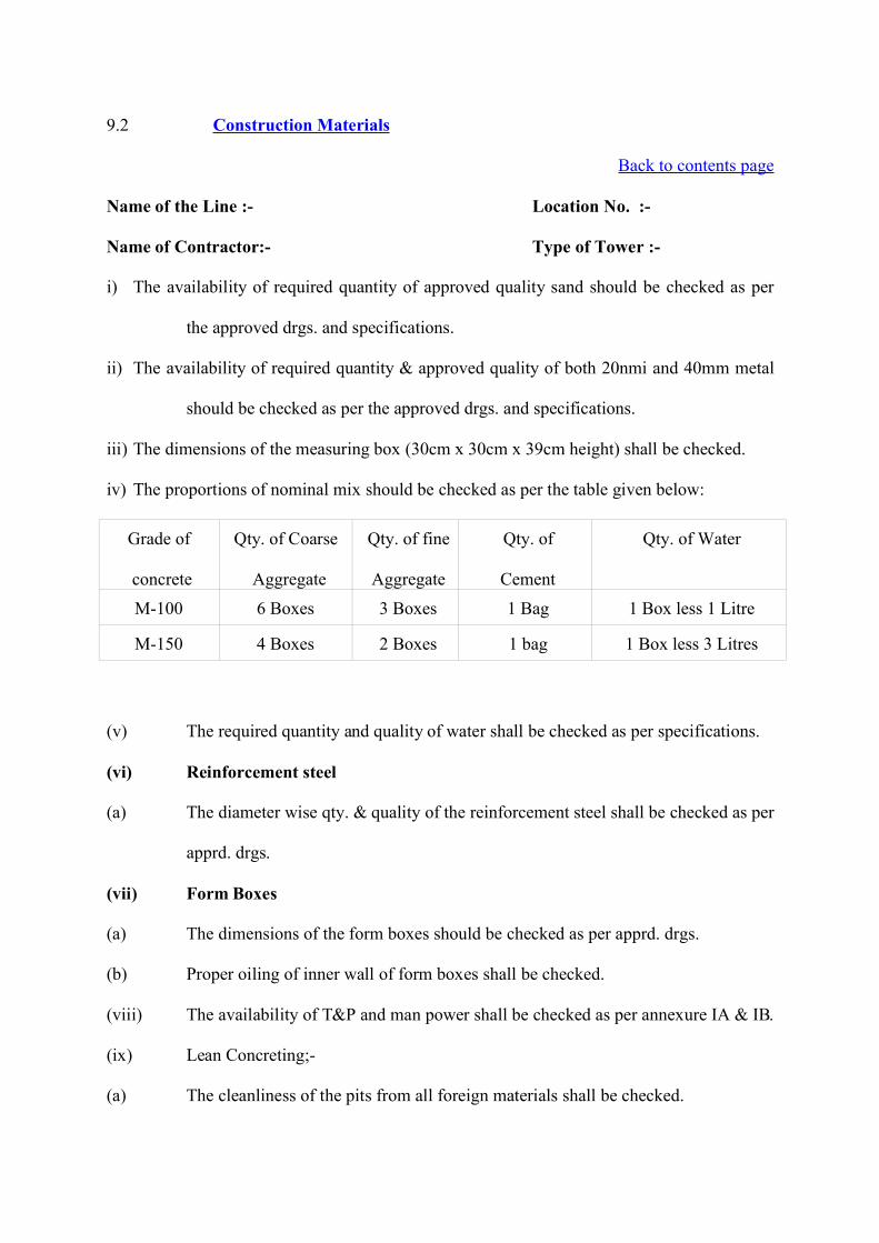
9.2 Construction Materials
Back to contents page
Name of the Line :- Location No. :-
Name of Contractor:- Type of Tower :-
i) The availability of required quantity of approved quality sand should be checked as per
the approved drgs. and specifications.
ii) The availability of required quantity & approved quality of both 20nmi and 40mm metal
should be checked as per the approved drgs. and specifications.
iii) The dimensions of the measuring box (30cm x 30cm x 39cm height) shall be checked.
iv) The proportions of nominal mix should be checked as per the table given below:
Grade of
concrete
Qty. of Coarse
Aggregate
Qty. of fine
Aggregate
Qty. of
Cement
Qty. of Water
M-100 6 Boxes 3 Boxes 1 Bag 1 Box less 1 Litre
M-150 4 Boxes 2 Boxes 1 bag 1 Box less 3 Litres
(v) The required quantity and quality of water shall be checked as per specifications.
(vi) Reinforcement steel
(a) The diameter wise qty. & quality of the reinforcement steel shall be checked as per
apprd. drgs.
(vii) Form Boxes
(a) The dimensions of the form boxes should be checked as per apprd. drgs.
(b) Proper oiling of inner wall of form boxes shall be checked.
(viii) The availability of T&P and man power shall be checked as per annexure IA & IB.
(ix) Lean Concreting;-
(a) The cleanliness of the pits from all foreign materials shall be checked.
(b) Proper dewatering of the pits shall be checked.
(c) Mix ratio of 1:3:6 concrete with 40mm metal shall be checked.
(d.a) Concrete mixing by mixer as per specn. shall be checked.
(d.b) Mixure running Time (Mixing Time-2 Min. ) shall be checked.
(e) De-watering of the pit shall be checked.
(f) The specified area and level of lean concrete in all the four pits shall be checked.
(g) The actual consumption of the cement bag as per approved drawing shall be
checked.
(x.a) Filling of excess excavation by the lean concrete shall be checked.
(x.b) The volume of excess lean concrete shall be measured and recorded.
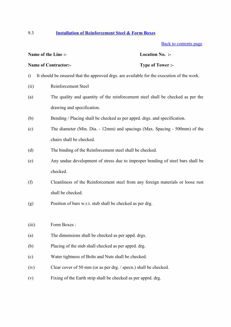
9.3 Installation of Reinforcement Steel & Form Boxes
Back to contents page
Name of the Line :- Location No. :-
Name of Contractor:- Type of Tower :-
i) It should be ensured that the approved drgs. are available for the execution of the work.
(ii) Reinforcement Steel
(a) The quality and quantity of the reinforcement steel shall be checked as per the
drawing and specification.
(b) Bending / Placing shall be checked as per apprd. drgs. and specification.
(c) The diameter (Min. Dia. - 12mm) and spacings (Max. Spacing - 500mm) of the
chairs shall be checked.
(d) The binding of the Reinforcement steel shall be checked.
(e) Any undue development of stress due to improper bending of steel bars shall be
checked.
(f) Cleanliness of the Reinforcement steel from any foreign materials or loose rust
shall be checked.
(g) Position of bars w.r.t. stub shall be checked as per drg.
(iii) Form Boxes :
(a) The dimensions shall be checked as per appd. drgs.
(b) Placing of the stub shall checked as per apprd. drg.
(c) Water tightness of Bolts and Nuts shall be checked.
(iv) Clear cover of 50 mm (or as per drg. / specn.) shall be checked.
(v) Fixing of the Earth strip shall be checked as per apprd. drg.
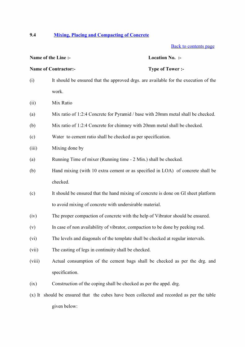
9.4 Mixing, Placing and Compacting of Concrete
Back to contents page
Name of the Line :- Location No. :-
Name of Contractor:- Type of Tower :-
(i) It should be ensured that the approved drgs. are available for the execution of the
work.
(ii) Mix Ratio
(a) Mix ratio of 1:2:4 Concrete for Pyramid / base with 20mm metal shall be checked.
(b) Mix ratio of 1:2:4 Concrete for chimney with 20mm metal shall be checked.
(c) Water to cement ratio shall be checked as per specification.
(iii) Mixing done by
(a) Running Time of mixer (Running time - 2 Min.) shall be checked.
(b) Hand mixing (with 10 extra cement or as specified in LOA) of concrete shall be
checked.
(c) It should be ensured that the hand mixing of concrete is done on GI sheet platform
to avoid mixing of concrete with undersirable material.
(iv) The proper compaction of concrete with the help of Vibrator should be ensured.
(v) In case of non availability of vibrator, compaction to be done by peeking rod.
(vi) The levels and diagonals of the template shall be checked at regular intervals.
(vii) The casting of legs in continuity shall be checked.
(viii) Actual consumption of the cement bags shall be checked as per the drg. and
specification.
(ix) Construction of the coping shall be checked as per the appd. drg.
(x) It should be ensured that the cubes have been collected and recorded as per the table
given below:
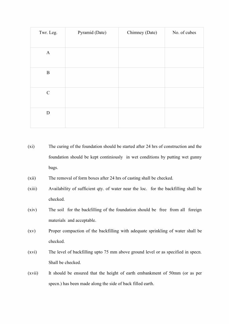
Twr. Leg. Pyramid (Date) Chimney (Date) No. of cubes
A
B
C
D
(xi) The curing of the foundation should be started after 24 hrs of construction and the
foundation should be kept continiously in wet conditions by putting wet gunny
bags.
(xii) The removal of form boxes after 24 hrs of casting shall be checked.
(xiii) Availability of sufficient qty. of water near the loc. for the backfilling shall be
checked.
(xiv) The soil for the backfilling of the foundation should be free from all foreign
materials and acceptable.
(xv) Proper compaction of the backfilling with adequate sprinkling of water shall be
checked.
(xvi) The level of backfilling upto 75 mm above ground level or as specified in specn.
Shall be checked.
(xvii) It should be ensured that the height of earth embankment of 50mm (or as per
specn.) has been made along the side of back filled earth.
(xviii) Proper curing of the chimney by wet gunny bags shall be checked.
(xix) Careful removal of template after complete back filling shall be checked.
(xx) Curing period of foundation and chimney checked as per specn. (Minimum period
of curing 14 days after concreting both in Morning & Evening).
(a) The date of start of curing and date of completion of curing shall be recorded.
(xxi) The arrangement for testing of the cubes as per approved FQP shall be checked.
(xxii) The removal of all the surplus materials from site shall be ensured.
Note : Foundn. Is cleared for tower erection subject to fulfillment of part (I) before tower
erection and part (II) in due course as per planning.
Part-II (i) Revetment Benching proposal status
(ii) Rivetment / Benching likely execution date
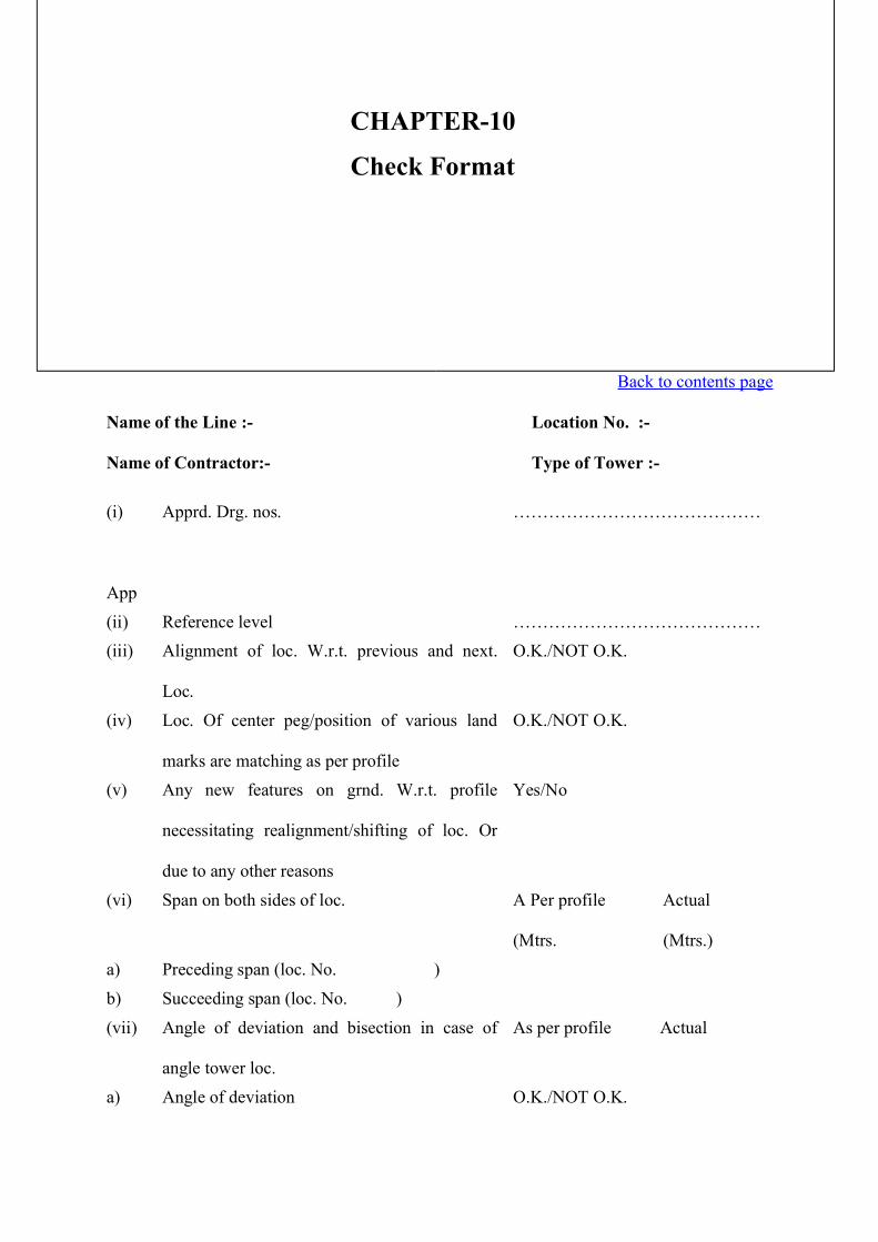
___________________________________________________________________________
CHAPTERTEN
___________________________________________________________________________
CHECK FORMAT
Back to contents page
1.0 Check format for Pit Marking
Back to contents page
Name of the Line :- Location No. :-
Name of Contractor:- Type of Tower :-
(i)
App
Apprd. Drg. nos. ……………………………………
(ii) Reference level ……………………………………(iii) Alignment of loc. W.r.t. previous and next.
Loc.
O.K./NOT O.K.
(iv) Loc. Of center peg/position of various land
marks are matching as per profile
O.K./NOT O.K.
(v) Any new features on grnd. W.r.t. profile
necessitating realignment/shifting of loc. Or
due to any other reasons
Yes/No
(vi) Span on both sides of loc. A Per profile Actual
(Mtrs. (Mtrs.)
a) Preceding span (loc. No. )
b) Succeeding span (loc. No. )
(vii) Angle of deviation and bisection in case of
angle tower loc.
As per profile Actual
a) Angle of deviation O.K./NOT O.K.
CHAPTER-10
Check Format
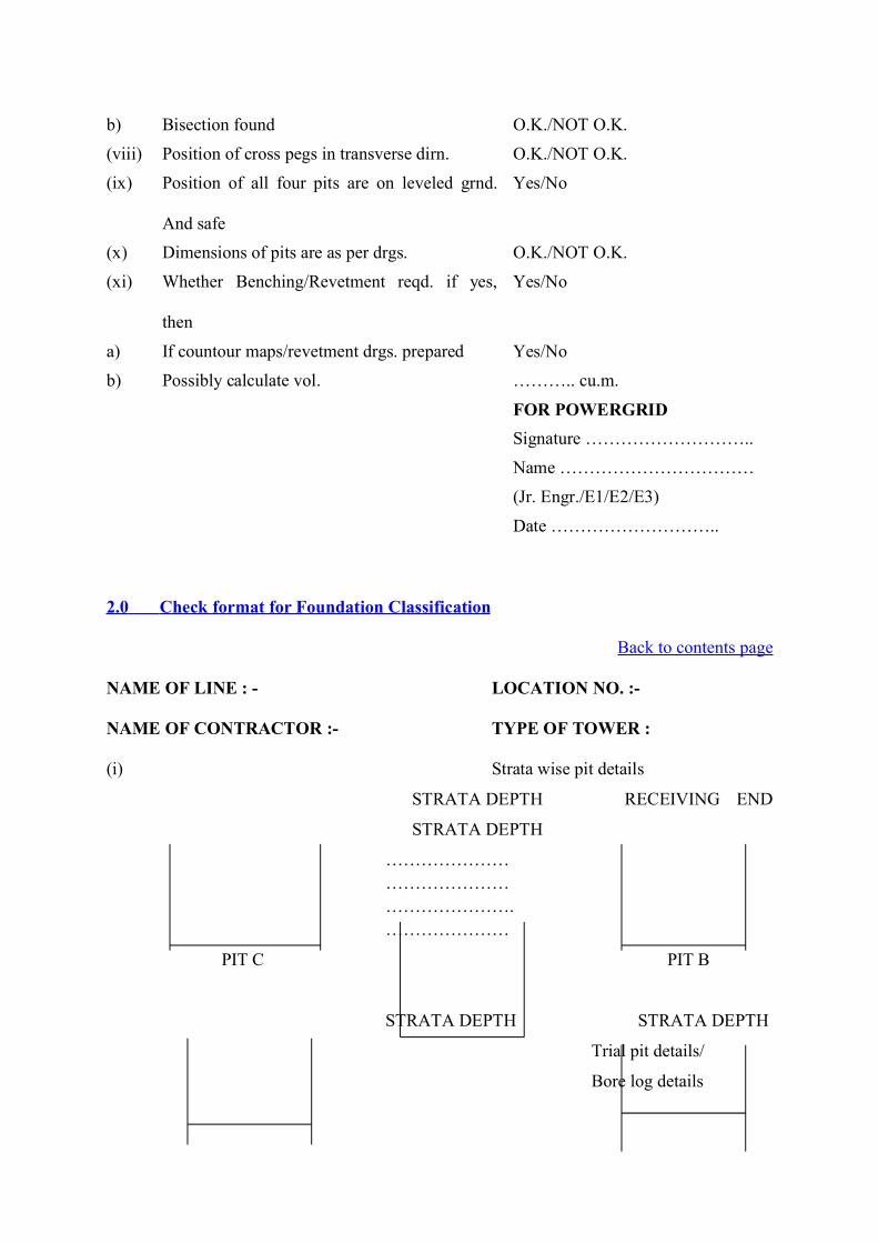
b) Bisection found O.K./NOT O.K.
(viii) Position of cross pegs in transverse dirn. O.K./NOT O.K.
(ix) Position of all four pits are on leveled grnd.
And safe
Yes/No
(x) Dimensions of pits are as per drgs. O.K./NOT O.K.
(xi) Whether Benching/Revetment reqd. if yes,
then
Yes/No
a) If countour maps/revetment drgs. prepared Yes/No
b) Possibly calculate vol. ……….. cu.m.
FOR POWERGRIDSignature ………………………..
Name ……………………………
(Jr. Engr./E1/E2/E3)
Date ………………………..
2.0 Check format for Foundation Classification
Back to contents page
NAME OF LINE : - LOCATION NO. :-
NAME OF CONTRACTOR :- TYPE OF TOWER :
(i) Strata wise pit details
STRATA DEPTH RECEIVING END
STRATA DEPTH
……………………………………………………….…………………
PIT C PIT B
STRATA DEPTH STRATA DEPTH
Trial pit details/
Bore log details
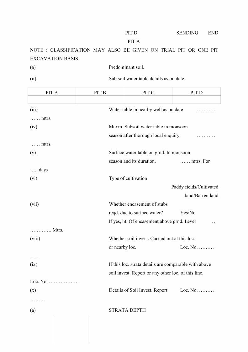
PIT D SENDING END
PIT A
NOTE : CLASSIFICATION MAY ALSO BE GIVEN ON TRIAL PIT OR ONE PIT
EXCAVATION BASIS.
(a) Predominant soil.
(ii) Sub soil water table details as on date.
PIT A PIT B PIT C PIT D
(iii) Water table in nearby well as on date …………
…… mtrs.
(iv) Maxm. Subsoil water table in monsoon
season after thorough local enquiry …………
…… mtrs.
(v) Surface water table on grnd. In monsoon
season and its duration. …… mtrs. For
….. days
(vi) Type of cultivation
Paddy fields/Cultivated
land/Barren land
(vii) Whether encasement of stubs
reqd. due to surface water? Yes/No
If yes, ht. Of encasement above grnd. Level …
…………. Mtrs.
(viii) Whether soil invest. Carried out at this loc.
or nearby loc. Loc. No. ………
……
(ix) If this loc. strata details are comparable with above
soil invest. Report or any other loc. of this line.
Loc. No. ………………
(x) Details of Soil Invest. Report Loc. No. ………
………
(a) STRATA DEPTH
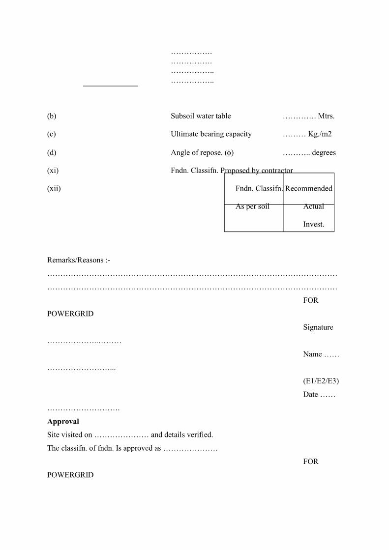
…………….…………….……………..……………..
(b) Subsoil water table …………. Mtrs.
(c) Ultimate bearing capacity ……… Kg./m2
(d) Angle of repose. () ……….. degrees
(xi) Fndn. Classifn. Proposed by contractor
(xii) Fndn. Classifn. Recommended
As per soil Actual
Invest.
Remarks/Reasons :-
…………………………………………………………………………………………………
…………………………………………………………………………………………………
FOR
POWERGRID
Signature
………………..………
Name ……
……………………...
(E1/E2/E3)
Date ……
……………………….
Approval
Site visited on ………………… and details verified.
The classifn. of fndn. Is approved as …………………
FOR
POWERGRID

Signature
………………..………
Name ……
……………………...
(Line
Inch./Grp. Head)
Date ……
……………………….
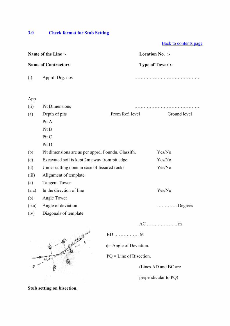
3.0 Check format for Stub Setting
Back to contents page
Name of the Line :- Location No. :-
Name of Contractor:- Type of Tower :-
(i)
App
Apprd. Drg. nos. ……………………………………
(ii) Pit Dimensions ……………………………………
(a) Depth of pits From Ref. level Ground level
Pit A
Pit BPit C
Pit D
(b) Pit dimensions are as per apprd. Foundn. Classifn. Yes/No
(c) Excavated soil is kept 2m away from pit edge Yes/No
(d) Under cutting done in case of fissured rocks Yes/No
(iii) Alignment of template(a) Tangent Tower
(a.a) In the direction of line Yes/No
(b) Angle Tower
(b.a) Angle of deviation …………. Degrees
(iv) Diagonals of template
AC ……………….. m
BD ……………. M
= Angle of Deviation.
PQ = Line of Bisection.
(Lines AD and BC are
perpendicular to PQ)
Stub setting on bisection.
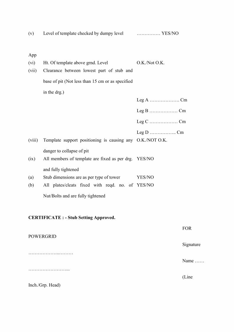
(v)
App
Level of template checked by dumpy level …………… YES/NO
(vi) Ht. Of template above grnd. Level O.K./Not O.K.
(vii) Clearance between lowest part of stub and
base of pit (Not less than 15 cm or as specified
in the drg.)Leg A ………………. Cm
Leg B ……………… Cm
Leg C ……………… Cm
Leg D …………….. Cm
(viii) Template support positioning is causing any
danger to collapse of pit
O.K./NOT O.K.
(ix) All members of template are fixed as per drg.
and fully tightened
YES/NO
(a) Stub dimensions are as per type of tower YES/NO
(b) All plates/cleats fixed with reqd. no. of
Nut/Bolts and are fully tightened
YES/NO
CERTIFICATE : - Stub Setting Approved.
FOR
POWERGRID
Signature
………………..………
Name ……
……………………...
(Line
Inch./Grp. Head)

Date ……
……………………….
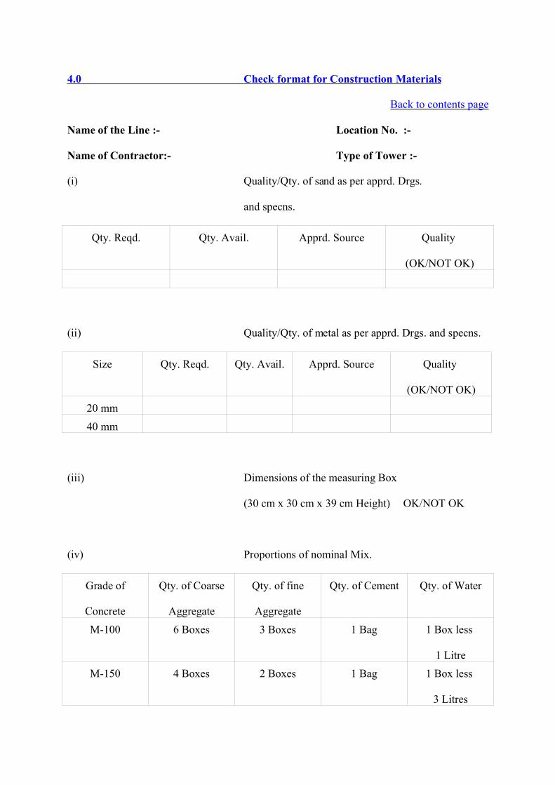
4.0 Check format for Construction Materials
Back to contents page
Name of the Line :- Location No. :-
Name of Contractor:- Type of Tower :-
(i) Quality/Qty. of sand as per apprd. Drgs.
and specns.
Qty. Reqd. Qty. Avail. Apprd. Source Quality
(OK/NOT OK)
(ii) Quality/Qty. of metal as per apprd. Drgs. and specns.
Size Qty. Reqd. Qty. Avail. Apprd. Source Quality
(OK/NOT OK)
20 mm
40 mm
(iii) Dimensions of the measuring Box
(30 cm x 30 cm x 39 cm Height) OK/NOT OK
(iv) Proportions of nominal Mix.
Grade of
Concrete
Qty. of Coarse
Aggregate
Qty. of fine
Aggregate
Qty. of Cement Qty. of Water
M-100 6 Boxes 3 Boxes 1 Bag 1 Box less
1 Litre
M-150 4 Boxes 2 Boxes 1 Bag 1 Box less
3 Litres
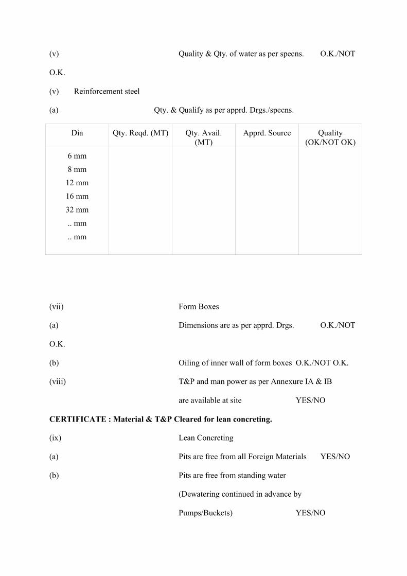
(v) Quality & Qty. of water as per specns. O.K./NOT
O.K.
(v) Reinforcement steel
(a) Qty. & Qualify as per apprd. Drgs./specns.
Dia Qty. Reqd. (MT) Qty. Avail.(MT)
Apprd. Source Quality(OK/NOT OK)
6 mm
8 mm12 mm
16 mm
32 mm
.. mm
.. mm
(vii) Form Boxes
(a) Dimensions are as per apprd. Drgs. O.K./NOT
O.K.
(b) Oiling of inner wall of form boxes O.K./NOT O.K.
(viii) T&P and man power as per Annexure IA & IB
are available at site YES/NO
CERTIFICATE : Material & T&P Cleared for lean concreting.
(ix) Lean Concreting
(a) Pits are free from all Foreign Materials YES/NO
(b) Pits are free from standing water
(Dewatering continued in advance by
Pumps/Buckets) YES/NO
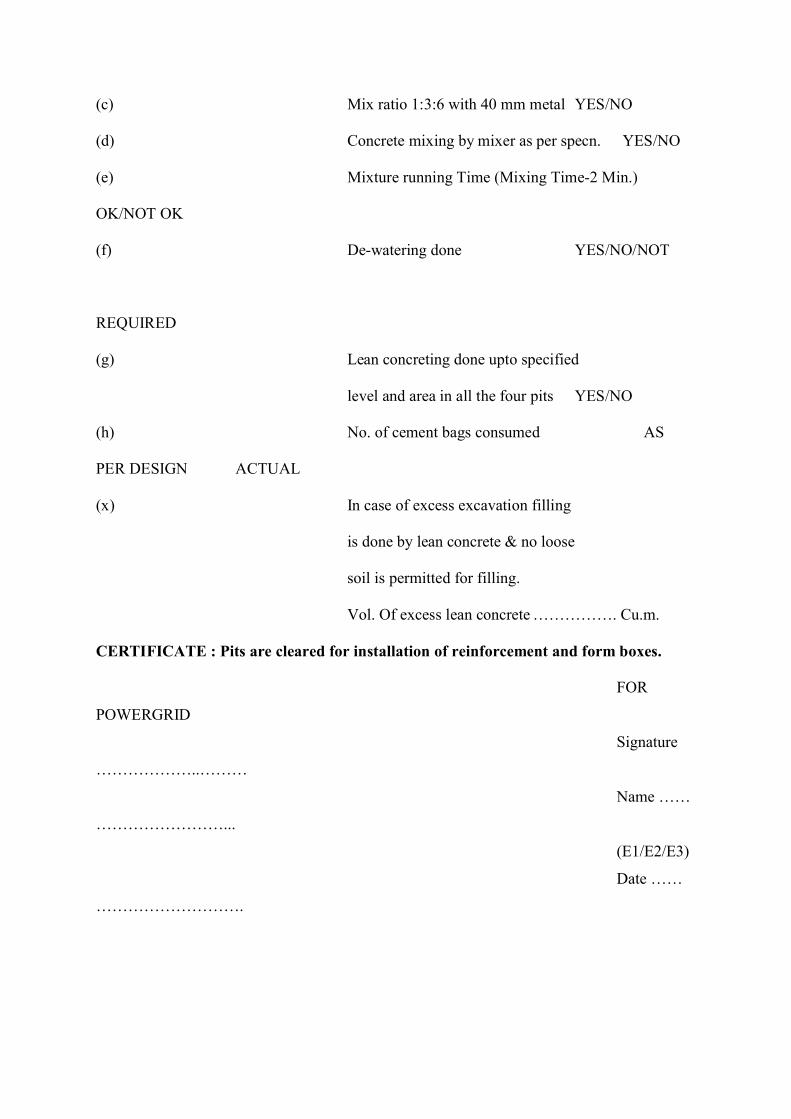
(c) Mix ratio 1:3:6 with 40 mm metal YES/NO
(d) Concrete mixing by mixer as per specn. YES/NO
(e) Mixture running Time (Mixing Time-2 Min.)
OK/NOT OK
(f) De-watering done YES/NO/NOT
REQUIRED
(g) Lean concreting done upto specified
level and area in all the four pits YES/NO
(h) No. of cement bags consumed AS
PER DESIGN ACTUAL
(x) In case of excess excavation filling
is done by lean concrete & no loose
soil is permitted for filling.
Vol. Of excess lean concrete ……………. Cu.m.
CERTIFICATE : Pits are cleared for installation of reinforcement and form boxes.
FOR
POWERGRID
Signature
………………..………
Name ……
……………………...
(E1/E2/E3)
Date ……
……………………….
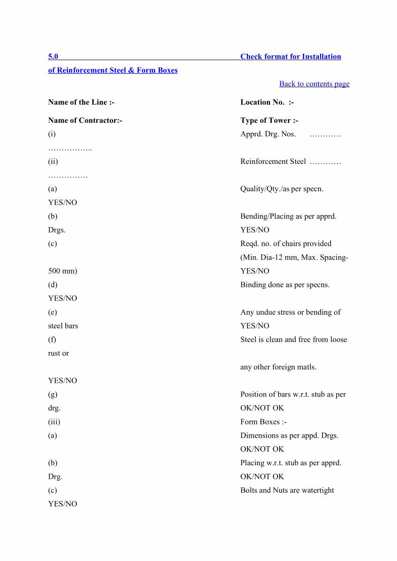
5.0 Check format for Installation
of Reinforcement Steel & Form Boxes
Back to contents page
Name of the Line :- Location No. :-
Name of Contractor:- Type of Tower :-
(i) Apprd. Drg. Nos. …………
……………..
(ii) Reinforcement Steel …………
……………
(a) Quality/Qty./as per specn.
YES/NO
(b) Bending/Placing as per apprd.
Drgs. YES/NO
(c) Reqd. no. of chairs provided
(Min. Dia-12 mm, Max. Spacing-
500 mm) YES/NO
(d) Binding done as per specns.
YES/NO
(e) Any undue stress or bending of
steel bars YES/NO
(f) Steel is clean and free from loose
rust or
any other foreign matls.
YES/NO
(g) Position of bars w.r.t. stub as per
drg. OK/NOT OK
(iii) Form Boxes :-
(a) Dimensions as per appd. Drgs.
OK/NOT OK
(b) Placing w.r.t. stub as per apprd.
Drg. OK/NOT OK
(c) Bolts and Nuts are watertight
YES/NO
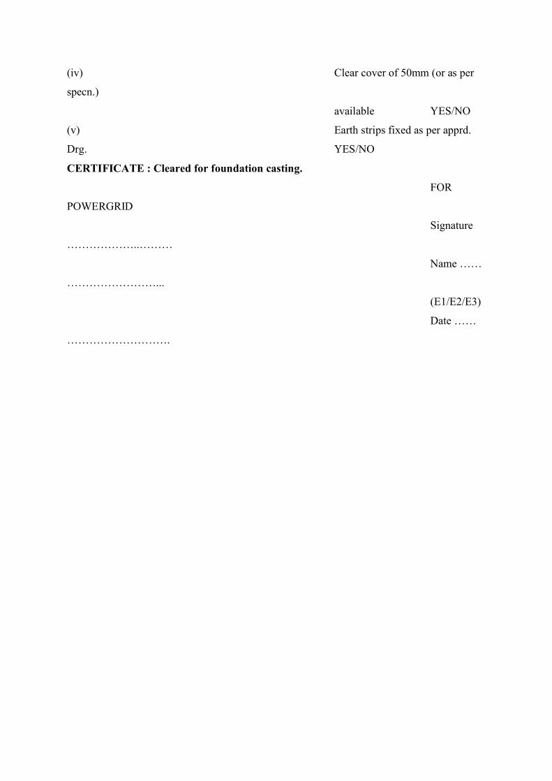
(iv) Clear cover of 50mm (or as per
specn.)
available YES/NO
(v) Earth strips fixed as per apprd.
Drg. YES/NO
CERTIFICATE : Cleared for foundation casting.
FOR
POWERGRID
Signature
………………..………
Name ……
……………………...
(E1/E2/E3)
Date ……
……………………….
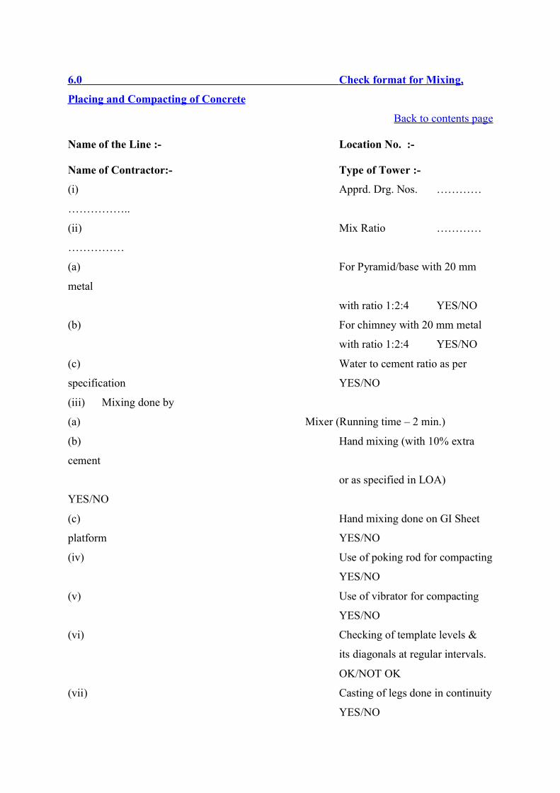
6.0 Check format for Mixing,
Placing and Compacting of Concrete
Back to contents page
Name of the Line :- Location No. :-
Name of Contractor:- Type of Tower :-
(i) Apprd. Drg. Nos. …………
……………..
(ii) Mix Ratio …………
……………
(a) For Pyramid/base with 20 mm
metal
with ratio 1:2:4 YES/NO
(b) For chimney with 20 mm metal
with ratio 1:2:4 YES/NO
(c) Water to cement ratio as per
specification YES/NO
(iii) Mixing done by
(a) Mixer (Running time – 2 min.)
(b) Hand mixing (with 10% extra
cement
or as specified in LOA)
YES/NO
(c) Hand mixing done on GI Sheet
platform YES/NO
(iv) Use of poking rod for compacting
YES/NO
(v) Use of vibrator for compacting
YES/NO
(vi) Checking of template levels &
its diagonals at regular intervals.
OK/NOT OK
(vii) Casting of legs done in continuity
YES/NO
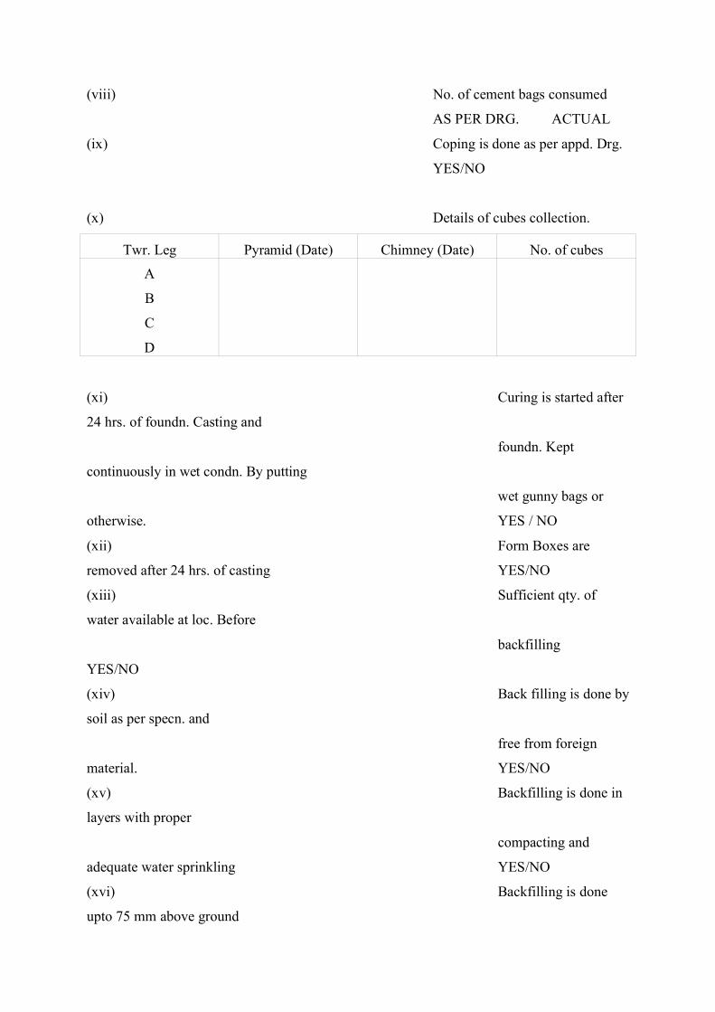
(viii) No. of cement bags consumed
AS PER DRG. ACTUAL
(ix) Coping is done as per appd. Drg.
YES/NO
(x) Details of cubes collection.
Twr. Leg Pyramid (Date) Chimney (Date) No. of cubes
A
B
C
D
(xi) Curing is started after
24 hrs. of foundn. Casting and
foundn. Kept
continuously in wet condn. By putting
wet gunny bags or
otherwise. YES / NO
(xii) Form Boxes are
removed after 24 hrs. of casting YES/NO
(xiii) Sufficient qty. of
water available at loc. Before
backfilling
YES/NO
(xiv) Back filling is done by
soil as per specn. and
free from foreign
material. YES/NO
(xv) Backfilling is done in
layers with proper
compacting and
adequate water sprinkling YES/NO
(xvi) Backfilling is done
upto 75 mm above ground
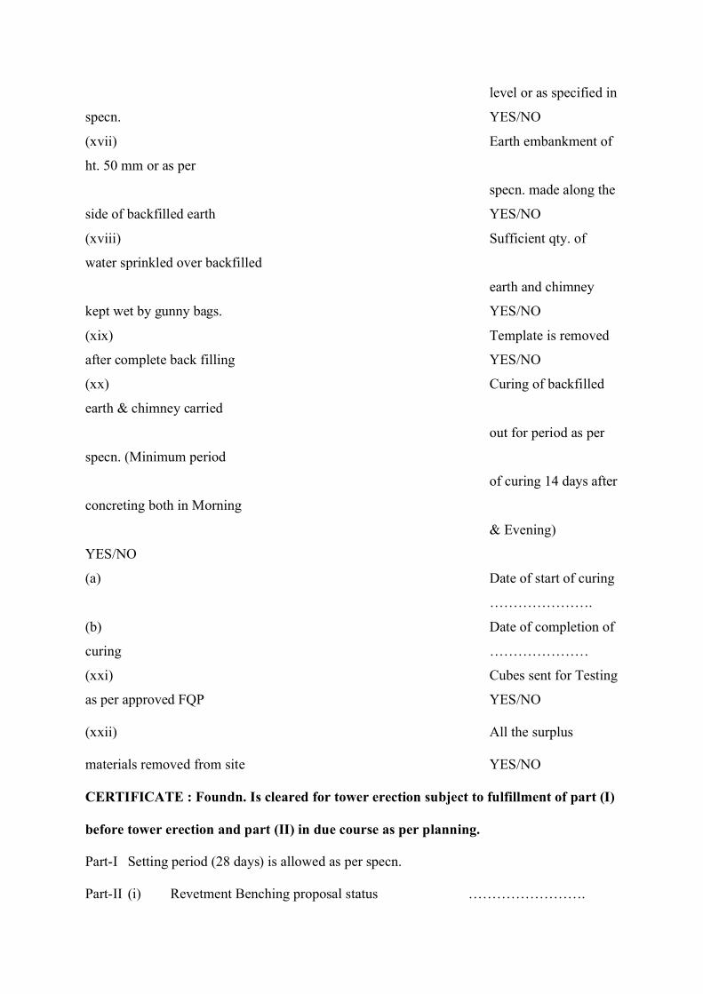
level or as specified in
specn. YES/NO
(xvii) Earth embankment of
ht. 50 mm or as per
specn. made along the
side of backfilled earth YES/NO
(xviii) Sufficient qty. of
water sprinkled over backfilled
earth and chimney
kept wet by gunny bags. YES/NO
(xix) Template is removed
after complete back filling YES/NO
(xx) Curing of backfilled
earth & chimney carried
out for period as per
specn. (Minimum period
of curing 14 days after
concreting both in Morning
& Evening)
YES/NO
(a) Date of start of curing
………………….
(b) Date of completion of
curing …………………
(xxi) Cubes sent for Testing
as per approved FQP YES/NO
(xxii) All the surplus
materials removed from site YES/NO
CERTIFICATE : Foundn. Is cleared for tower erection subject to fulfillment of part (I)
before tower erection and part (II) in due course as per planning.
Part-I Setting period (28 days) is allowed as per specn.
Part-II (i) Revetment Benching proposal status …………………….

(ii) Revetment/Benching likely execution date ………………………
FOR
POWERGRID
Signature
………………..………
Name ……
……………………...
(E1/E2/E3)
Date ……
……………………….
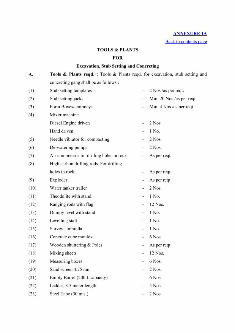
ANNEXURE-IA
Back to contents page
TOOLS & PLANTS
FOR
Excavation, Stub Setting and Concreting
A. Tools & Plants reqd. : Tools & Plants reqd. for excavation, stub setting and
concreting gang shall be as follows :
(1) Stub setting templates - 2 Nos./as per reqt.
(2) Stub setting jacks - Min. 20 Nos./as per reqt.
(3) Form Boxes/chimneys - Min. 4 Nos./as per reqt.
(4) Mixer machine
Diesel Engine driven - 2 Nos.
Hand driven - 1 No.
(5) Needle vibrator for compacting - 2 Nos.
(6) De-watering pumps - 2 Nos.
(7) Air compressor for drilling holes in rock - As per reqt.
(8) High carbon drilling rods. For drilling
holes in rock - As per reqt.
(9) Exploder - As per reqt.
(10) Water tanker trailer - 2 Nos.
(11) Theodolite with stand - 1 No.
(12) Ranging rods with flag - 12 Nos.
(13) Dumpy level with stand - 1 No.
(14) Levelling staff - 1 No.
(15) Survey Umbrella - 1 No.
(16) Concrete cube moulds - 6 Nos.
(17) Wooden shuttering & Poles - As per reqt.
(18) Mixing sheets - 12 Nos.
(19) Measuring boxes - 6 Nos.
(20) Sand screen 4.75 mm - 2 Nos.
(21) Empty Barrel (200 L capacity) - 6 Nos.
(22) Ladder, 3.5 meter length - 5 Nos.
(23) Steel Tape (30 mts.) - 2 Nos.
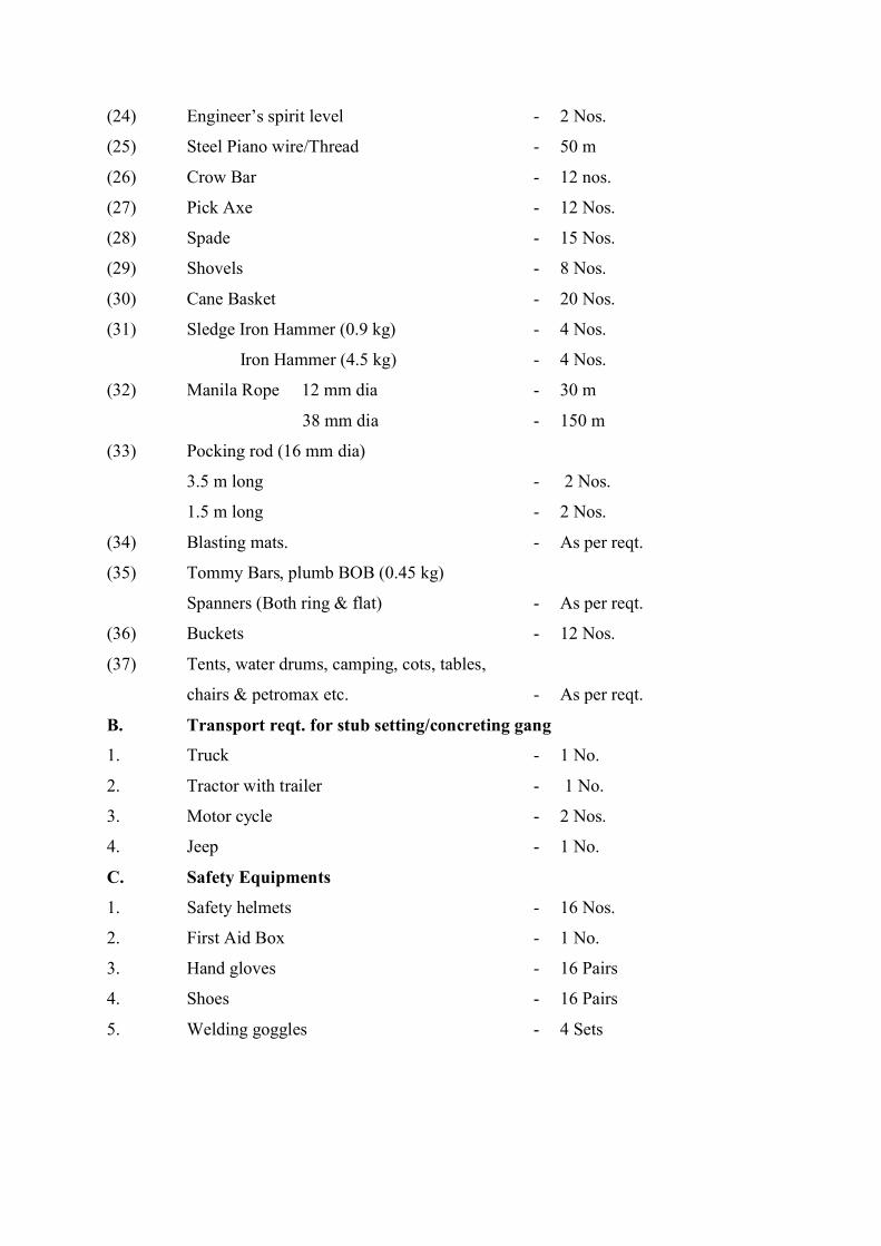
(24) Engineer’s spirit level - 2 Nos.
(25) Steel Piano wire/Thread - 50 m
(26) Crow Bar - 12 nos.
(27) Pick Axe - 12 Nos.
(28) Spade - 15 Nos.
(29) Shovels - 8 Nos.
(30) Cane Basket - 20 Nos.
(31) Sledge Iron Hammer (0.9 kg) - 4 Nos.
Iron Hammer (4.5 kg) - 4 Nos.
(32) Manila Rope 12 mm dia - 30 m
38 mm dia - 150 m
(33) Pocking rod (16 mm dia)
3.5 m long - 2 Nos.
1.5 m long - 2 Nos.
(34) Blasting mats. - As per reqt.
(35) Tommy Bars, plumb BOB (0.45 kg)
Spanners (Both ring & flat) - As per reqt.
(36) Buckets - 12 Nos.
(37) Tents, water drums, camping, cots, tables,
chairs & petromax etc. - As per reqt.
B. Transport reqt. for stub setting/concreting gang
1. Truck - 1 No.
2. Tractor with trailer - 1 No.
3. Motor cycle - 2 Nos.
4. Jeep - 1 No.
C. Safety Equipments
1. Safety helmets - 16 Nos.
2. First Aid Box - 1 No.
3. Hand gloves - 16 Pairs
4. Shoes - 16 Pairs
5. Welding goggles - 4 Sets
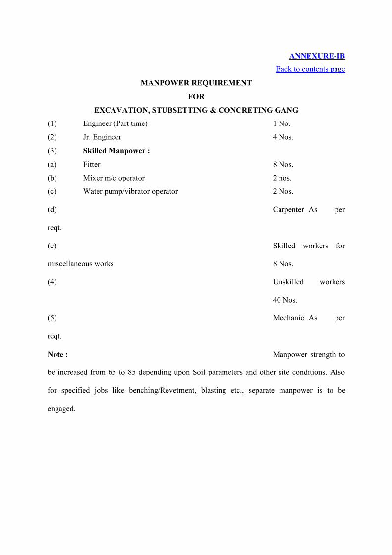
ANNEXURE-IB
Back to contents page
MANPOWER REQUIREMENT
FOR
EXCAVATION, STUBSETTING & CONCRETING GANG
(1) Engineer (Part time) 1 No.
(2) Jr. Engineer 4 Nos.
(3) Skilled Manpower :
(a) Fitter 8 Nos.
(b) Mixer m/c operator 2 nos.
(c) Water pump/vibrator operator 2 Nos.
(d) Carpenter As per
reqt.
(e) Skilled workers for
miscellaneous works 8 Nos.
(4) Unskilled workers
40 Nos.
(5) Mechanic As per
reqt.
Note : Manpower strength to
be increased from 65 to 85 depending upon Soil parameters and other site conditions. Also
for specified jobs like benching/Revetment, blasting etc., separate manpower is to be
engaged.
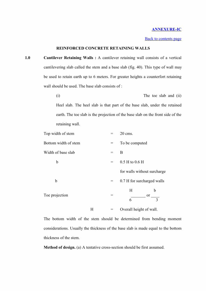
ANNEXURE-IC
Back to contents page
REINFORCED CONCRETE RETAINING WALLS
1.0 Cantilever Retaining Walls : A cantilever retaining wall consists of a vertical
cantilevering slab called the stem and a base slab (fig. 40). This type of wall may
be used to retain earth up to 6 meters. For greater heights a counterfort retaining
wall should be used. The base slab consists of :
(i) The toe slab and (ii)
Heel slab. The heel slab is that part of the base slab, under the retained
earth. The toe slab is the projection of the base slab on the front side of the
retaining wall.
Top width of stem = 20 cms.
Bottom width of stem = To be computed
Width of base slab = B
b = 0.5 H to 0.6 H
for walls without surcharge
b = 0.7 H for surcharged walls
H bToe projection = _______ or ____
6 3
H = Overall height of wall.
The bottom width of the stem should be determined from bending moment
considerations. Usually the thickness of the base slab is made equal to the bottom
thickness of the stem.
Method of design. (a) A tentative cross-section should be first assumed.
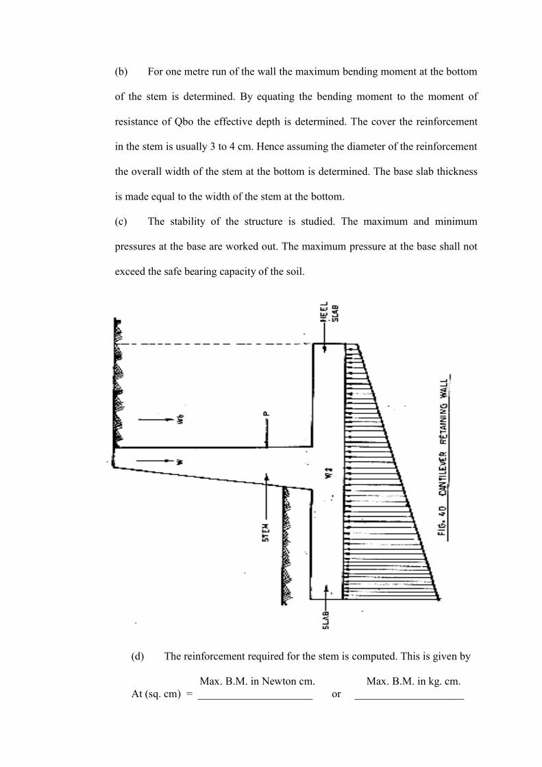
(b) For one metre run of the wall the maximum bending moment at the bottom
of the stem is determined. By equating the bending moment to the moment of
resistance of Qbo the effective depth is determined. The cover the reinforcement
in the stem is usually 3 to 4 cm. Hence assuming the diameter of the reinforcement
the overall width of the stem at the bottom is determined. The base slab thickness
is made equal to the width of the stem at the bottom.
(c) The stability of the structure is studied. The maximum and minimum
pressures at the base are worked out. The maximum pressure at the base shall not
exceed the safe bearing capacity of the soil.
(d) The reinforcement required for the stem is computed. This is given by
Max. B.M. in Newton cm. Max. B.M. in kg. cm.At (sq. cm) = _____________________ or ____________________
14000 x 0.87 d 1400 x 0.87 d
(e) Calculate the maximum bending moment for the toe slab. The toe slab
is designed as a cantilever and acted upon by upward soil reaction. The
depth provided is checked for the bending moment. A cover of 5 cm.
To 6 cm. may be provided to reinforcement in the base slab.
(f) Calculate the maximum bending moment for the heel slab. The heel
slab is also designed as a cantilever subjected to downward loads
consisting of its own weight, the weight of the soil above it and super
load and any loading due to the surcharge, and upward soil reactions.
The reinforcement required is now determined.
(g) The tendency for the wall to slide forward due to the lateral earth
pressure should be investigated. A factor of safety of at least 1.5 shall
be provided against sliding. If the factor of safety is insufficient a key
(also called rib or cut off wall) would be designed to prevent the lateral
movement of the structure. (See Fig. 43).
Figs. 41 and 42 show how the various components of a cantilevering
wall can fail.
The above figures must obviously give an idea as to where the reinforcements
are required. Fro the stem, reinforcement is required near the earth side. For
the toe slab the reinforcement is required at the bottom of the slab. For the heel
slab the reinforcement is required at the top of the slab. For the key the
reinforcement is required on that side where convexity of bending will occur
(see Figs. 42 and 43). Fig. 43 shows a section of an R.C. retaining wall
showing places where the main reinforcements are required.
Usually the requirement of reinforcement for the key will be small and hence
alternate bars of toe slab may be continued and bent down to form the
reinforcement for the key. The key may alternatively be provided under the
stem so that alternate bars of the stem reinforcement may serve as
reinforcement for the key.
Shear reinforcement. Shear reinforcement is not normally used in retaining
walls. The resistance of the concrete itself must be sufficient to resist the
sharing forces imposed.
Distribution steel. Horizontal distribution steel should be provided in both the
stem and the base slab. This reinforcement shall not be less than 0.15% of the
gross area of concrete.
Expansion and contraction joints. Keyed expansion and contraction joints
should be provided at 30 m intervals.
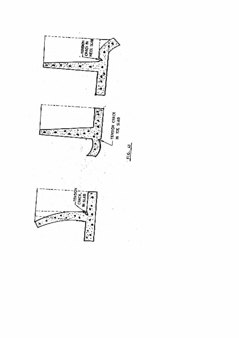
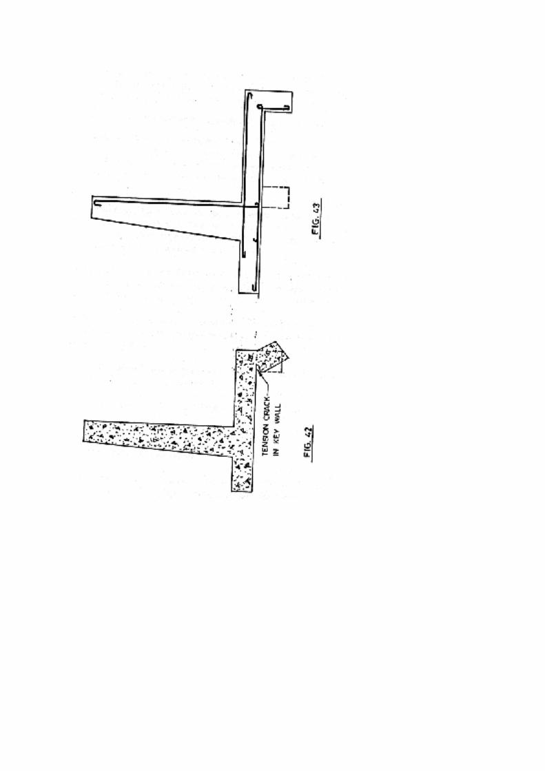
2.0 Counterfort Retaining Walls
Retaining walls over 5.5 metres in height are usually made of the counterfort type. The
various components of such a wall are shown in Fig. 44.
(i) Upright slab. The upright slab will be designed as a continuous slab
spanning on the counterforts and subjected to lateral earth pressure. Let the
lateral, horizontal pressure intensity at the bottom of the upright slab be p
per sq. metre. Consider the bottom 1 metre deep strip of the upright slab. If
the spacing of counterforts be 1 metres centre to centre then the maximum
being moment for theupright slab = pI2/12. The thickness required to suit
this bending moment may now be computed. The slab is usually built of
the same thickness. The main reinforcement requirement may now be
calculated. This steel runs horizontally, its requirement being away from
the earth side at sections mid-way between the counterforts and near the
earth side at the sections on the counterforts.
The slab shall also be provided with distribution steel at not less
than 0.15% of the gross area of the section. The distribution steel is placed
vertically near both the faces, since the upright slab is considerably thick.
These bars should form a mesh with the horizontal bars. Hence these bars
will have to be supported by additional horizontal bars at certain places
where main horizontal bars are not forming a mesh with them.
(ii) The base slab. The width of the base slab may be made 0.6 H to
0.7 H where H is the overall height of the retaining wall. The base slab
consists of the toe slab and the heel slab. The toe projection is usually one-
fourth of the total width of the base slab.
Heel slab. The heel slab should be designed as a continuous
horizontal slab with the counterforts as the supports. The slab is designed
as a continuous slab consisting of continuous strips parallel to the wall.
Each stip is uniformly loaded; but the loading on the various strips
varies from a maximum at the heel edge to a minimum near the wall.
The loading on a strip of heel slab will consist of the following :
(a) Dead load of the strip
(b) Weight of earth above the strip
(c) Vertical component of lateral pressure in the case of earth
surcharged at an angle. If the surcharge angle is a, then the intensity
of vertical component of lateral pressure
= Cp wh’ sin tan
Cos – (cos2 – cos2)1/2
Where Cp = cos _______________________ Cos + (cos2 – cos2)1/2
h’ = height of earth above the strip
= angle of repose.
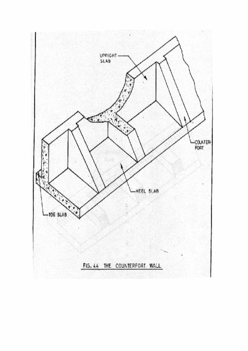
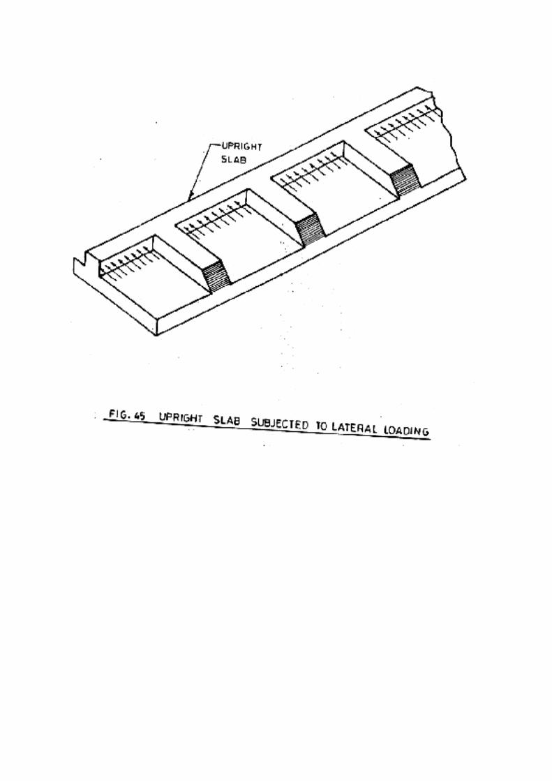
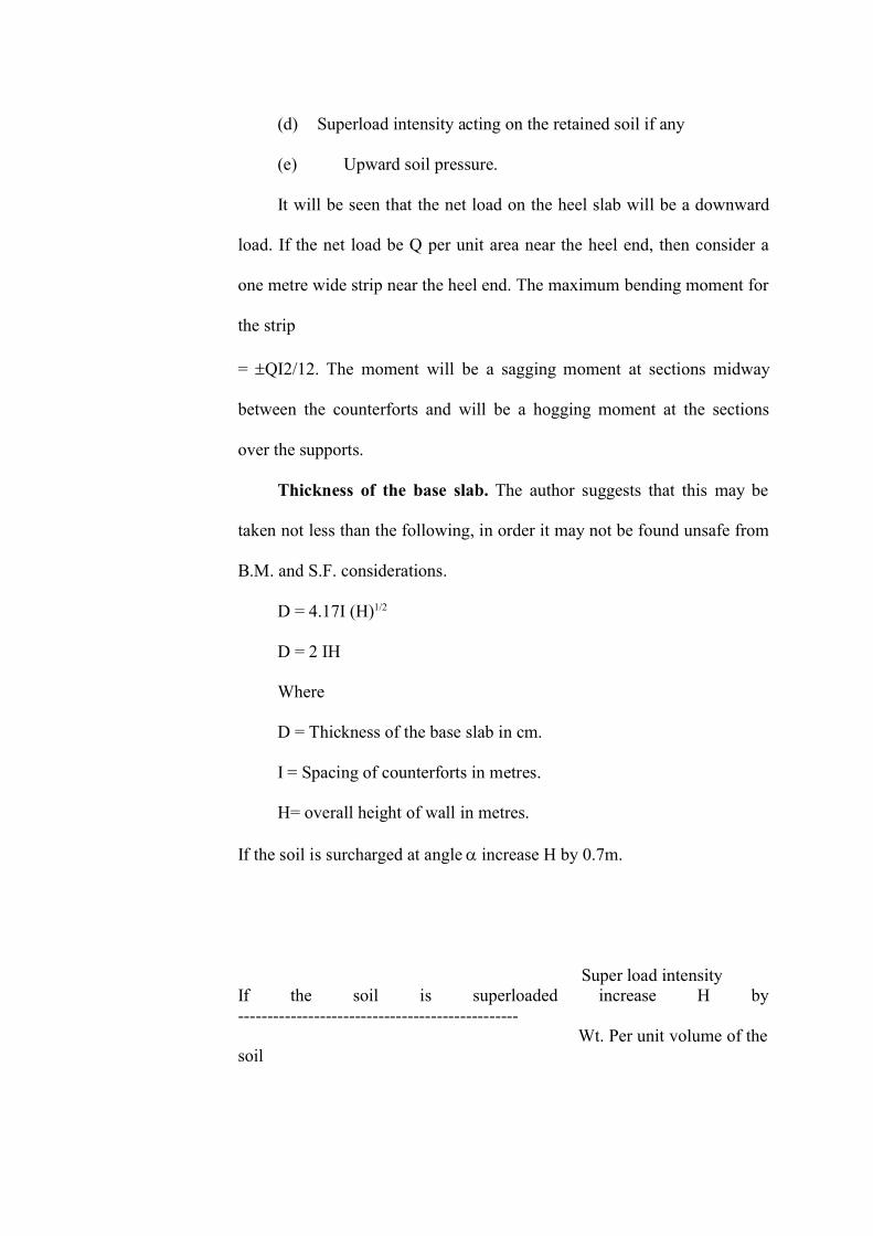
(d) Superload intensity acting on the retained soil if any
(e) Upward soil pressure.
It will be seen that the net load on the heel slab will be a downward
load. If the net load be Q per unit area near the heel end, then consider a
one metre wide strip near the heel end. The maximum bending moment for
the strip
= QI2/12. The moment will be a sagging moment at sections midway
between the counterforts and will be a hogging moment at the sections
over the supports.
Thickness of the base slab. The author suggests that this may be
taken not less than the following, in order it may not be found unsafe from
B.M. and S.F. considerations.
D = 4.17I (H)1/2
D = 2 IH
Where
D = Thickness of the base slab in cm.
I = Spacing of counterforts in metres.
H= overall height of wall in metres.
If the soil is surcharged at angle increase H by 0.7m.
Super load intensityIf the soil is superloaded increase H by------------------------------------------------ Wt. Per unit volume of thesoil
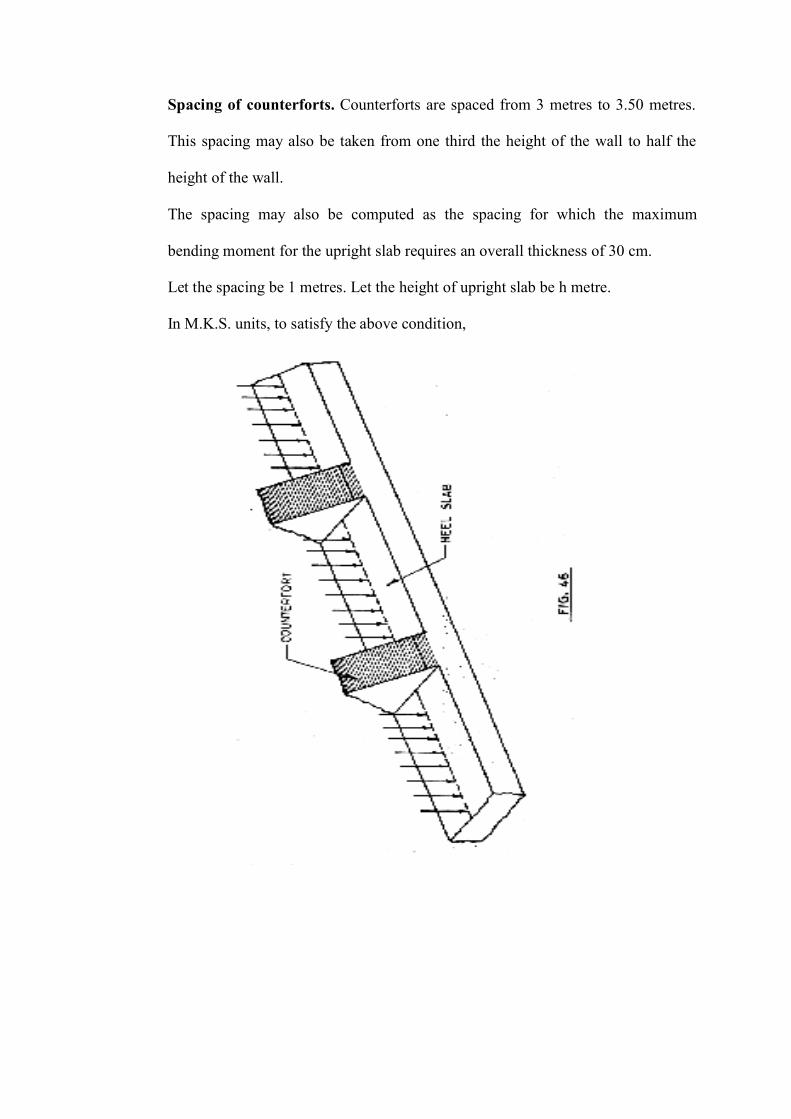
Spacing of counterforts. Counterforts are spaced from 3 metres to 3.50 metres.
This spacing may also be taken from one third the height of the wall to half the
height of the wall.
The spacing may also be computed as the spacing for which the maximum
bending moment for the upright slab requires an overall thickness of 30 cm.
Let the spacing be 1 metres. Let the height of upright slab be h metre.
In M.K.S. units, to satisfy the above condition,
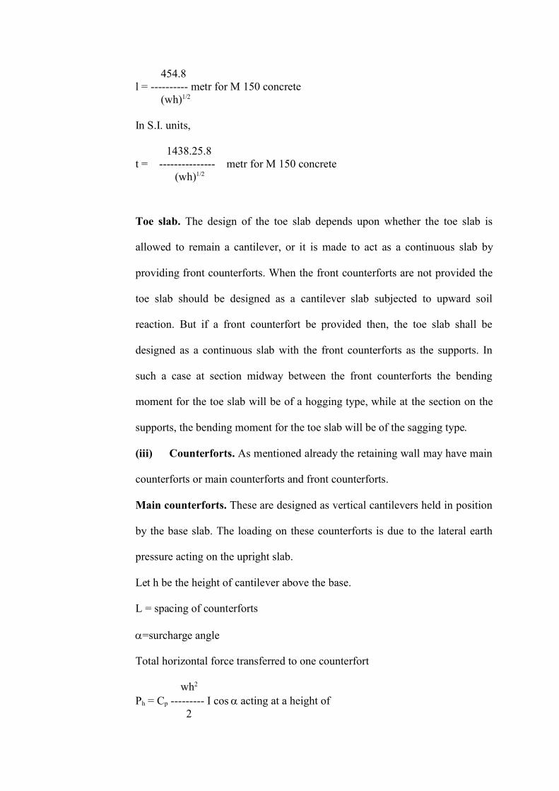
454.8l = ---------- metr for M 150 concrete (wh)1/2
In S.I. units,
1438.25.8t = --------------- metr for M 150 concrete (wh)1/2
Toe slab. The design of the toe slab depends upon whether the toe slab is
allowed to remain a cantilever, or it is made to act as a continuous slab by
providing front counterforts. When the front counterforts are not provided the
toe slab should be designed as a cantilever slab subjected to upward soil
reaction. But if a front counterfort be provided then, the toe slab shall be
designed as a continuous slab with the front counterforts as the supports. In
such a case at section midway between the front counterforts the bending
moment for the toe slab will be of a hogging type, while at the section on the
supports, the bending moment for the toe slab will be of the sagging type.
(iii) Counterforts. As mentioned already the retaining wall may have main
counterforts or main counterforts and front counterforts.
Main counterforts. These are designed as vertical cantilevers held in position
by the base slab. The loading on these counterforts is due to the lateral earth
pressure acting on the upright slab.
Let h be the height of cantilever above the base.
L = spacing of counterforts
=surcharge angle
Total horizontal force transferred to one counterfort
wh2
Ph = Cp --------- I cos acting at a height of 2
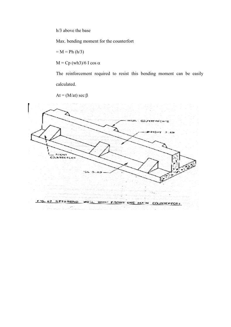
h/3 above the base
Max. bending moment for the counterfort
= M = Ph (h/3)
M = Cp (wh3)/6 I cos
The reinforcement required to resist this bending moment can be easily
calculated.
At = (M/at) sec
Where = inclination of the reinforment with the normal to the horizontal section of
counterfort (i.e., inclination of the reinforcement with the vertical).
We know At (M/a) (M/d) (M/h) approximately
At (h3/h)
At h2
If At1 and At2 are the areas of steel required at depths h1 and h2
We have At1/At2 = h12/h2
2
But At is proportional to the number of bars.
Let n be the number of bars at the depth h
n1 be the number of bars at the depth h1
n2 be the number of bars at the depth h2
n3 be the number of bars at the depth h3
Then we have
n1/n = h12/h2 …………………………………….. (1)
n2/n = h22/h2 ……………………………………. (2)
n3/n = h32/h2 …………………………………… (3)
and so on.
Hence at what depth a certain number of bars can be curtailed, can be
determined.
Front counterforts. These are designed as horizontal cantilevers. The loading
on these will be due to the upward soil reaction on the toe slab. It is quite
likely that the front counterfort will be subjected to considerable shear force.
Hence shear stirrups of two or four legs must also be provided.
The main reinforcement of the main counterfort and also that of the front
counterfort should be embedded into the base slab for sufficient length to
develop the necessary bond strength. The bars of the main counterfort should
be securely anchored at the bottom by bending them back into the base slab.
In the case of a wall provided with main as front counterforts the critical
section for the max. bending moment for the main counterforts shall be taken
at a level corresponding to the top level of the front counterfort.
Horizontal ties connecting the main counterforts and upright slab.
Horizontal links of two legs are provided connecting the main counterfort and
the upright slab to tie the wall to the counterfort and also to resist diagonal
tension in the counterfort. These links must be looped around the main
reinforcement of the counterfort. Fig. 47 shows the horizontal links and Figs.
48 and 49 show two alternative ways in which the horizontal links may be
provided.
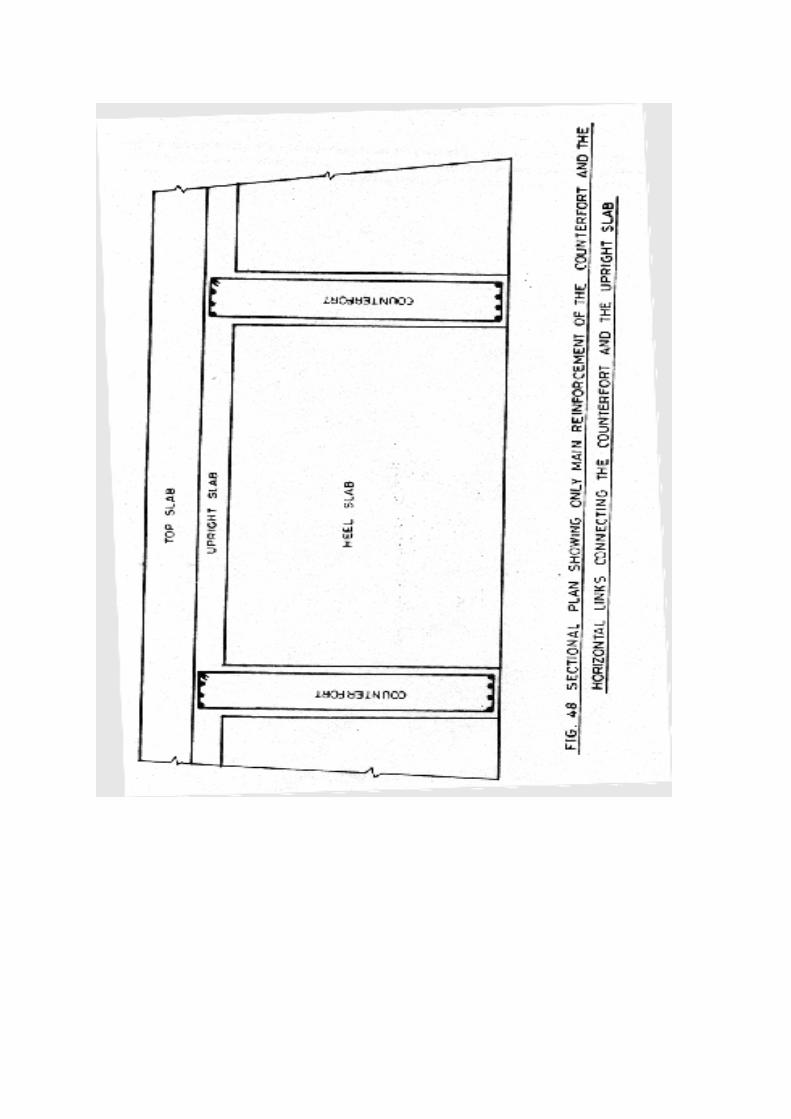
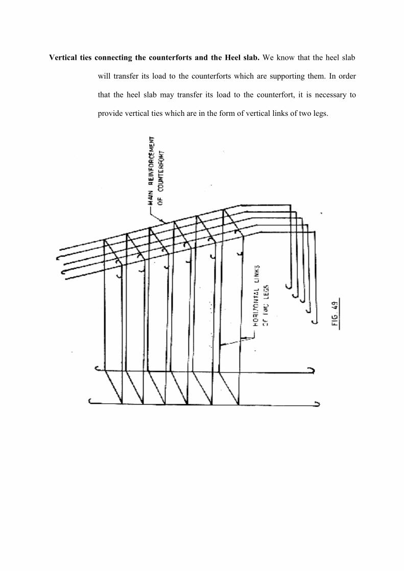
Vertical ties connecting the counterforts and the Heel slab. We know that the heel slab
will transfer its load to the counterforts which are supporting them. In order
that the heel slab may transfer its load to the counterfort, it is necessary to
provide vertical ties which are in the form of vertical links of two legs.

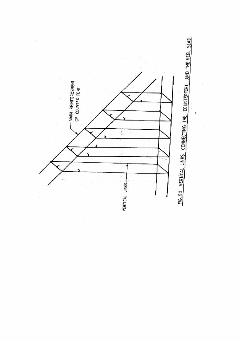
----------------------------------------------------------------------------------------------------------------
BIBLIOGRAPHY----------------------------------------------------------------------------------------------------------------
(1) “Transmission Line Structure” by S.S. Murthy and A.R. Santhakumar.
(2) “Manual on Transmission Line Towers” – CBI&P – Technical Report No. 9.
(3) “Workshop on Transmission Line” – CBI&P-Vadodara (29th Nov. –2nd Dec. 94).
(4) “Symposium on Design & Protection of 400 KV Transmission Lines” – CBI&P –
Publication No. 131.
(5) “Code of Practice for Design and Construction of Pile Foundation” – IS 2911 (Part-I
to Part-IV).
(6) “Pile Design and Construction Practice” – M.J. Tomlinson.
(7) “Manual on Transmission Line Towers” – Central Board of Irrigation and Power.
(8) “Handbook on under-reamed and Bored compaction Pile Foundation” – Central
Building research institute, Roorkee.
(9) “Construction Manual, Part-II, Transmission Line Construction” SRTS – Power Grid
Corporation of India Ltd.
(10) “Soil Mechanics and Foundation Engineering” by K.R. Arora.
(11) “Modern Geotechnical Engineering” by Alam Singh.
(12) “Foundation Design” by Wayne C. Teng.
(13) “Construction Planning equipment & Methods” by Robert L. Peurifoy and William B.
Ledbetter.
(14) “Foundation analysis and Design” by Joseph E Borles.