![Profibus PA Fieldbus Display [ Revision 2 ] and Fieldbus ... Instruments... · Profibus PA Fieldbus Display [ Revision 2 ] and Fieldbus Indicator Fieldbus Interface Guide. ... Siemens](https://static.fdocuments.us/doc/165x107/5b2fe38e7f8b9ae16e8da83d/profibus-pa-fieldbus-display-revision-2-and-fieldbus-instruments.jpg)
Foundation Fieldbus RMA803 Remote Indicator …...Revision 3 Foundation Fieldbus RMA803 Remote...
144
Honeywell Process Solutions Foundation Fieldbus RMA803 Remote Indicator User's Guide 34-ST-25-51 Revision 4 March 2020
Transcript of Foundation Fieldbus RMA803 Remote Indicator …...Revision 3 Foundation Fieldbus RMA803 Remote...
Honeywell Process Solutions
Foundation Fieldbus RMA803 Remote Indicator
User's Guide
34-ST-25-51Revision 4
March 2020
Page ii Foundation Fieldbus RMA803 Remote Indicator User's Guide Revision 4
Copyrights, Notices and Trademarks
© Copyright 2020 by Honeywell, Inc. Revision 4, March 2020
While this information is presented in good faith and believed to be accurate, Honeywell disclaims the implied warranties of merchantability and fitness for a particular purpose and makes no express warranties except as may be stated in its written agreement with and for its customers. In no event is Honeywell liable to anyone for any indirect, special or consequential damages. The information and specifications in this document are subject to change without notice. Honeywell, PlantScape, Experion PKS, and TotalPlant are registered trademarks of Honeywell International Inc. Other brand or product names are trademarks of their respective owners.
Honeywell Process Solutions 1250 W Sam Houston Pkwy S
Houston, TX 77042
Revision 4 Foundation Fieldbus RMA803 Remote Indicator User's Guide Page iii
About This Document This guide provides the details of programming Honeywell RMA803 Remote Indicator for applications involving FOUNDATION Fieldbus protocol. For installation, wiring, and maintenance information, refer to the RMA803 Remote Indicator User Manual. The configuration of your Remote Indicator depends on the mode of operation and the options selected for it with respect to operating controls, displays and mechanical installation. An RMA803 Remote Indicator can be digitally integrated with: • Experion PKS, you need to supplement the information in this document with the data and procedures in
the Experion PDF Collection.
Release Information
Document Name Foundation Fieldbus RMA803 Remote Indicator
User's Guide
Document ID 34-ST-25-51
Release Number
Publication Date
1st Release 1 June 2014
Ferrite core info added 2 September 2014
FM Approvals updated. Certs updated to include 801 3 February 2019
SAEx approval added 4 March 2020
References The following list identifies all documents that may be sources of reference for material discussed in this publication. Quick Start Installation Guide, # 34-ST-25-52 HART/DE Option User Manual, Document # 34-ST-25-40
Page iv Foundation Fieldbus RMA803 Remote Indicator User's Guide Revision 4
Patent Notice The Honeywell Remote Indicator family is covered by one or more of the following U. S. Patents: 5,485,753; 5,811,690; 6,041,659; 6,055,633; 7,786,878; 8,073,098; and other patents pending.
Support and Contact Information For Europe, Asia Pacific, North and South America contact details, see back page or refer to the appropriate Honeywell Solution Support web site: Honeywell Corporate www.honeywellprocess.com Honeywell Process Solutions https://www.honeywellprocess.com/remote-meter-assemblies Training Classes www.honeywellprocess.com/en-US/training
Telephone and Email Contacts
Area Organization Phone Number
United States and Canada Honeywell Inc.
1-800-343-0228 Customer Service 1-800-423-9883 Global Technical Support
Global Email Support
Honeywell Process Solutions [email protected]
Field Product Sales
Honeywell Process Solutions [email protected]
Revision 4 Foundation Fieldbus RMA803 Remote Indicator User's Guide Page v
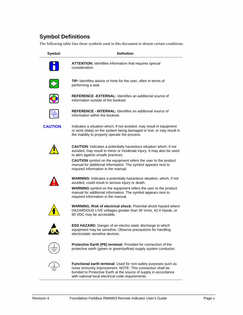
Symbol Definitions The following table lists those symbols used in this document to denote certain conditions.
Symbol Definition
ATTENTION: Identifies information that requires special consideration.
TIP: Identifies advice or hints for the user, often in terms of performing a task.
REFERENCE -EXTERNAL: Identifies an additional source of information outside of the bookset.
REFERENCE - INTERNAL: Identifies an additional source of information within the bookset.
CAUTION
Indicates a situation which, if not avoided, may result in equipment or work (data) on the system being damaged or lost, or may result in the inability to properly operate the process.
CAUTION: Indicates a potentially hazardous situation which, if not avoided, may result in minor or moderate injury. It may also be used to alert against unsafe practices. CAUTION symbol on the equipment refers the user to the product manual for additional information. The symbol appears next to required information in the manual.
WARNING: Indicates a potentially hazardous situation, which, if not avoided, could result in serious injury or death. WARNING symbol on the equipment refers the user to the product manual for additional information. The symbol appears next to required information in the manual.
WARNING, Risk of electrical shock: Potential shock hazard where HAZARDOUS LIVE voltages greater than 30 Vrms, 42.4 Vpeak, or 60 VDC may be accessible.
ESD HAZARD: Danger of an electro-static discharge to which equipment may be sensitive. Observe precautions for handling electrostatic sensitive devices.
Protective Earth (PE) terminal: Provided for connection of the protective earth (green or green/yellow) supply system conductor.
Functional earth terminal: Used for non-safety purposes such as noise immunity improvement. NOTE: This connection shall be bonded to Protective Earth at the source of supply in accordance with national local electrical code requirements.

Page vi Foundation Fieldbus RMA803 Remote Indicator User's Guide Revision 4
Symbol Definition
Earth Ground: Functional earth connection. NOTE: This connection shall be bonded to Protective Earth at the source of supply in accordance with national and local electrical code requirements.
Chassis Ground: Identifies a connection to the chassis or frame of the equipment shall be bonded to Protective Earth at the source of supply in accordance with national and local electrical code requirements.

Revision 4 Foundation Fieldbus RMA803 Remote Indicator User's Guide Page vii
Terms and Acronyms
Term Definition
Alarm The detection of a block leaving a particular state and when it returns back to that state.
Analog Input (function block)
One of the standard function blocks define by the Foundation Fieldbus
AP Absolute Pressure
Application A software program that interacts with blocks, events and objects. One application may interface with other applications or contain more than one application.
AWG American Wire Gauge
Block A logical software unit that makes up one named copy of a block and the associated parameters its block type specifies. It can be a resource block, transducer block or a function block.
Configuration (of a system or device)
A step in system design: selecting functional units, assigning their locations and identifiers, and defining their interconnections.
Device A physical entity capable of performing one or more specific functions. Examples include Remote Indicators, actuators, controllers, operator interfaces.
DCS (Distributed Control System)
DD Device Description
Device Description Description of FBAPs within a device. Files that describe the software objects in a device, such as function blocks and parameters. The DD binary are created by passing DD source files through a standard tool called a tokenizer.
Device Description Language
A standardized programming language (similar to C) used to write device description source files.
Device Tag The Physical Device Tag of the device as specified in the Foundation Fieldbus specifications.
DP Differential Pressure
DTM Device Type Manager
EDD Electronic Device Description
EDDL Electronic Device Description Language EEPROM Electrically Erasable Programmable Read Only Memory
EMI Electromagnetic Interference
Event An instantaneous occurrence that is significant to scheduling block execution and to the operational (event) view of the application.
Field Device A fieldbus-compatible device that contains and executes function blocks.
Page viii Foundation Fieldbus RMA803 Remote Indicator User's Guide Revision 4
Term Definition
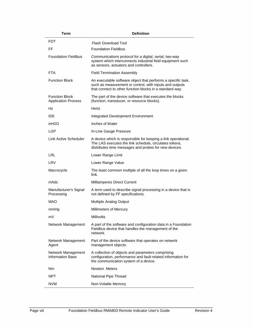
FDT Flash Download Tool FF Foundation Fieldbus
Foundation Fieldbus Communications protocol for a digital, serial, two-way system which interconnects industrial field equipment such as sensors, actuators and controllers.
FTA Field Termination Assembly
Function Block An executable software object that performs a specific task, such as measurement or control, with inputs and outputs that connect to other function blocks in a standard way.
Function Block Application Process
The part of the device software that executes the blocks (function, transducer, or resource blocks).
Hz Hertz
IDE Integrated Development Environment
inH2O Inches of Water
LGP In-Line Gauge Pressure
Link Active Scheduler A device which is responsible for keeping a link operational. The LAS executes the link schedule, circulates tokens, distributes time messages and probes for new devices.
LRL Lower Range Limit
LRV Lower Range Value
Macrocycle The least common multiple of all the loop times on a given link.
mAdc Milliamperes Direct Current
Manufacturer's Signal Processing
A term used to describe signal processing in a device that is not defined by FF specifications.
MAO Multiple Analog Output
mmHg Millimeters of Mercury
mV Millivolts
Network Management A part of the software and configuration data in a Foundation Fieldbus device that handles the management of the network.
Network Management Agent
Part of the device software that operates on network management objects.
Network Management Information Base
A collection of objects and parameters comprising configuration, performance and fault-related information for the communication system of a device.
Nm Newton. Meters
NPT National Pipe Thread
NVM Non-Volatile Memory

Revision 4 Foundation Fieldbus RMA803 Remote Indicator User's Guide Page ix
Term Definition
Object Dictionary Definitions and descriptions of network visible objects of a device. There are various object dictionaries within a device. The dictionaries contain objects and their associated parameters which support the application in which they are contained.
Objects Entities within the FBAP, such as blocks, alert objects, trend objects, parameters, display lists, etc.
OOS Out Of Service
P Pressure
Pa Measured static pressure in PV4 algorithm
Parameters A value or variable which resides in block objects
Pdp Measured differential pressure in Pascals in PV4 algorithm
PM Process Manager
Proportional Integral Derivative control
A standard control algorithm. Also refers to a PID function block.
PSI Pounds per Square Inch
PSIA Pounds per Square Inch Absolute
Pu Static pressure at upstream point
PV Process Variable
PWA Printed Wiring Assembly
RFI Radio Frequency Interference
RMA Remote Meter Assembly
RTD Resistance Temperature Detector
Stack The software component that implement the Foundation Fieldbus communications protocol specifications, including FMS, FAS, DLL, SM and NM.
Status A coded value that qualifies dynamic variables (parameters) in function blocks. This value is usually passed along with the value from block to block. Status is fully defined in the FF FBAP specifications.
System Management Provides services that coordinate the operation of various devices in a distributed fieldbus system.
System Management Agent
Part of the device software that operates on system management objects.
System Management Information Base
A collection of objects and parameters comprising configuration and operational information used for control of system management operations.
TAC Technical Assistance Center
Trim Point A selected reference point at which a measurement is calibrated.
URL Upper Range Limit

Page x Foundation Fieldbus RMA803 Remote Indicator User's Guide Revision 4
Term Definition
URV Upper Range Value
US Universal Station
Vac Volts Alternating Current
Vdc Volts Direct Current
Virtual Communication Reference
A defined communication endpoint. Fieldbus communications can primarily only take place along an active communications "path" that consists of two VCR endpoints.
Virtual Field Device A logical grouping of "user layer" functions. Function blocks are grouped into a VFD, and system and network management are grouped into a VFD. For example, to establish communications between a transducer block and a function block, a VCR must be defined at the transducer block and a VCR must be defined at the function block.

Revision 4 Foundation Fieldbus RMA803 Remote Indicator User's Guide Page xi
Contents
1. INTRODUCTION ........................................................................... 1
1.1 About the RMA803 Remote Indicator ............................................................ 1
1.2 Features and Options ..................................................................................... 3
1.3 RMA803 major assembly and electronic housing components................. 4 1.4 Features of a Remote Indicator ..................................................................... 5
1.5 RMA803 Remote Indicator Nameplate .......................................................... 6
1.6 Safety Certification Information .................................................................... 6
1.7 Display Options ............................................................................................... 6
1.8 Optional 3-Button Assembly .......................................................................... 6
2. GETTING STARTED ..................................................................... 7
2.1 Verifying the installation ................................................................................ 7 Verifying Remote Indicator installation tasks .......................................................................... 7
2.2 Verifying communication with the Remote Indicator .................................. 8 Identify the Remote Indicator ................................................................................................. 8
2.3 Establishing communication with host systems ......................................... 9 Device Description (DD) ......................................................................................................... 9 Enhanced Device Description (EDD) ..................................................................................... 9 Device Type Manager (DTM) ................................................................................................. 9
3. INSTALLATION AND STARTUP ................................................ 11
3.1 Installation Site Evaluation .......................................................................... 11
3.2 Display Installation Precautions .................................................................. 11
3.3 Mounting Remote Indicator .......................................................................... 11 Summary .............................................................................................................................. 11 Mounting Dimensions........................................................................................................... 12 Bracket Mounting Procedure ................................................................................................ 12
3.4 Wiring a Remote Indicator ............................................................................ 13 Overview .............................................................................................................................. 13 Wiring Procedure ................................................................................................................. 13 Fieldbus Network Wiring ...................................................................................................... 14 Lightning Protection ............................................................................................................. 14 Supply Voltage Limiting Requirements ................................................................................ 14 Explosion-Proof Conduit Seal .............................................................................................. 14
4. OPERATION ................................................................................ 15
4.1 Overview ........................................................................................................ 15
4.2 Three-Button Operation ................................................................................ 15 4.3 Menu Navigation ........................................................................................... 16
4.4 Data Entry ...................................................................................................... 16

Page xii Foundation Fieldbus RMA803 Remote Indicator User's Guide Revision 4
4.5 Editing a Numeric Value ............................................................................... 17 Selecting a new setting from a list of choices ...................................................................... 17 The Advanced Display Menus ............................................................................................. 18
4.6 Advanced Displays ....................................................................................... 25 Button operation during monitoring ...................................................................................... 27
5. RMA803 FF REMOTE INDICATOR CONFIGURATION ............. 28
5.1 Importing the RMA803 FF Device Description (DD) files .......................... 28 Importing the DD to Experion PKS....................................................................................... 28
5.2 Configuring the function block application process ................................. 32 About the Function Block Application Process (FBAP) ........................................................ 32 Block Alarms ........................................................................................................................ 32 Process Alarms .................................................................................................................... 34
5.3 Resource block ............................................................................................. 35 Configuring the Resource block ........................................................................................... 35 RESTART ............................................................................................................................ 35 Execution ............................................................................................................................. 36 CYCLE TYPE ...................................................................................................................... 36 MEMORY ............................................................................................................................. 36 MAX NOTIFY ....................................................................................................................... 36 FEATURES .......................................................................................................................... 36 Reports ................................................................................................................................ 36 SOFT W LOCK and HARD W LOCK ................................................................................... 37 Field Diagnostics.................................................................................................................. 38 Parameter List ..................................................................................................................... 41
5.4 Diagnostic Transducer block ....................................................................... 45 Execution ............................................................................................................................. 45 Parameter List ..................................................................................................................... 46
5.5 LCD Transducer block .................................................................................. 48 Execution ............................................................................................................................. 48 Advanced Display ................................................................................................................ 48 Parameters List .................................................................................................................... 51
5.6 Proportional Integral Derivative (PID) block with auto tune ..................... 54 Execution ............................................................................................................................. 55 Auto tuning ........................................................................................................................... 58 Auto tuning procedure .......................................................................................................... 58 Parameter list ....................................................................................................................... 59 Attributes .............................................................................................................................. 63
5.7 Input Selector block ...................................................................................... 64 Execution ............................................................................................................................. 64 Parameters List .................................................................................................................... 66 Attributes .............................................................................................................................. 68
5.8 Integrator block ............................................................................................. 69 Execution ............................................................................................................................. 69 Parameters List .................................................................................................................... 75 Attributes .............................................................................................................................. 77
5.9 Arithmetic block ............................................................................................ 78 Execution ............................................................................................................................. 78 Parameter List ..................................................................................................................... 81 Attributes .............................................................................................................................. 82
5.10 Signal Characterizer block ....................................................................... 83 Execution ............................................................................................................................. 83 Parameter list ....................................................................................................................... 85 Attributes .............................................................................................................................. 86

Revision 4 Foundation Fieldbus RMA803 Remote Indicator User's Guide Page xiii
5.11 MAO Block ................................................................................................. 87 Execution ............................................................................................................................. 87 Parameter list ....................................................................................................................... 88 Attributes .............................................................................................................................. 89
5.12 Configuring the Remote Indicator using Field Device Manager (FDM) system 89
6. RMA803 FF REMOTE INDICATOR OPERATION ...................... 90
6.1 Operational considerations.......................................................................... 90 LAS Capability ..................................................................................................................... 90 Special Non-volatile parameters and NVM Wear-out ........................................................... 90 Mode Restricted Writes to Parameters ................................................................................ 90
6.2 Configuration of the RMA803 Remote Indicator using Handheld (HH) ... 90
6.3 Performing block instantiation .................................................................... 91 About block instantiation ...................................................................................................... 91 Block instantiation using Experion PKS ............................................................................... 91
7. RMA803 FF REMOTE INDICATOR MAINTENANCE ................. 92
7.1 Overview ........................................................................................................ 92 7.2 Preventive Maintenance Practices and Schedules ................................... 92
7.3 Replacing the Local Display and Communication Electronic Assembly 92
7.4 Downloading the firmware ........................................................................... 94 About firmware download feature ........................................................................................ 94 Class 3 ................................................................................................................................. 94 Recommendations ............................................................................................................... 94 Downloading the File............................................................................................................ 95
7.5 Licensing for Function Blocks .................................................................... 96
8. RMA803 FF REMOTE INDICATOR TROUBLESHOOTING ....... 97
8.1 Troubleshooting overview ........................................................................... 97 Device status and faults ....................................................................................................... 97
8.2 Troubleshooting the Remote Indicator ....................................................... 98 Device not visible on the network ......................................................................................... 98 Incorrect or non-compatible tools ......................................................................................... 99
8.3 Troubleshooting blocks ............................................................................. 100 Non-functioning blocks ....................................................................................................... 100 Troubleshooting block configuration errors ........................................................................ 100 Troubleshooting the Resource block .................................................................................. 100 Troubleshooting the Diagnostics Transducer block ........................................................... 101 Troubleshooting the LCD Transducer block ....................................................................... 102 Troubleshooting the Proportional Integral Derivative (PID) block ....................................... 103 Troubleshooting the Input Selector block ........................................................................... 104 Troubleshooting the Integrator block .................................................................................. 106 Troubleshooting the Arithmetic block ................................................................................. 107 Troubleshooting the Signal Characterizer block ................................................................. 108 Resolving the block configuration errors ............................................................................ 109
8.4 Device Diagnostics ..................................................................................... 110 RMA803 FF Remote Indicator memory.............................................................................. 110 Performing diagnostics in the background ......................................................................... 110 BLOCK_ERR parameter .................................................................................................... 110 Background Diagnostics Execution, BLOCK_TEST parameter ......................................... 110

Page xiv Foundation Fieldbus RMA803 Remote Indicator User's Guide Revision 4
8.5 Restoring the Remote Indicator to default settings ................................ 111 Remote Indicator Diagnostics ............................................................................................ 111 Function Block Faults ......................................................................................................... 111
8.6 Understanding simulation mode ............................................................... 112 About simulation mode jumper .......................................................................................... 112 Setting simulation jumper ................................................................................................... 112 Enabling simulation mode .................................................................................................. 113 Simulation mode truth table ............................................................................................... 113
8.7 Understanding write protection ................................................................. 114 8.8 Critical Diagnostics Screens ..................................................................... 114
Fault Conditions and Recommended Corrective Actions ................................................... 114
9. PARTS LIST .............................................................................. 115
9.1 Overview ...................................................................................................... 115
APPENDIX A. PRODUCT CERTIFICATIONS ................................... 118
10. INDEX ........................................................................................ 126

Revision 4 Foundation Fieldbus RMA803 Remote Indicator User's Guide Page xv
Tables Table 1: Feature and Options .......................................................................................... 3 Table 2: Available Display Characteristics ...................................................................... 6 Table 3: Remote Indicator installation verification tasks ................................................. 7 Table 4: Remote Indicator parameters ............................................................................ 8 Table 5: Three-Button Option Functions ....................................................................... 16 Table 6: Three-Button Data Entry.................................................................................. 17 Table 7: Advanced Display Main Menu Structure ......................................................... 18 Table 8: Diagnostics Menu ............................................................................................ 18 Table 9: Display Setup Menus ....................................................................................... 19 Table 10: Information Menus ......................................................................................... 22 Table 11: Advanced Displays with PV Format Display Indications ............................... 26 Table 12: Bit mapping of the BLOCK_ERR ................................................................... 32 Table 13: Priority for Alarms .......................................................................................... 34 Table 14: Diagnostic Definitions .................................................................................... 38 Table 15: Resource block parameters .......................................................................... 41 Table 16: Diagnostic Transducer block parameters ...................................................... 46 Table 17: LCD parameters ............................................................................................ 49 Table 18: LCD Transducer block parameters ............................................................... 51 Table 19: PID Tuning parameters ................................................................................. 57 Table 20: PID block parameters .................................................................................... 59 Table 21: Input Selector block parameters .................................................................... 66 Table 22: Integrator block parameters .......................................................................... 75 Table 23: Arithmetic block parameters .......................................................................... 81 Table 24: Signal Characterizer block parameters ......................................................... 85 Table 25: MAO block parameters .................................................................................. 88 Table 26: Resource block ............................................................................................ 100 Table 27: Diagnostics Transducer block ..................................................................... 101 Table 28: LCD Transducer block ................................................................................. 102 Table 29: PID block ..................................................................................................... 103 Table 30: Input Selector block ..................................................................................... 104 Table 31: Integrator block ............................................................................................ 106 Table 32: Arithmetic block ........................................................................................... 107 Table 33: Signal Characterizer block........................................................................... 108 Table 34: Resolving block configuration errors ........................................................... 109 Table 35: Diagnostics .................................................................................................. 110 Table 36: Setting the Simulation Jumper .................................................................... 113 Table 37: Simulation Mode Truth Table ...................................................................... 113 Table 38: Write lock ..................................................................................................... 114 Table 39: Fault Conditions and Recommended Corrective Actions. ........................... 114 Table 40: Summary List of Recommended Spare Parts ............................................. 115 Table 41: Pipe and Wall Bracket Parts (Refer to Figure 25) ....................................... 115 Table 42: Remote Indicator Major Assemblies ............................................................ 117
Page xvi Foundation Fieldbus RMA803 Remote Indicator User's Guide Revision 4
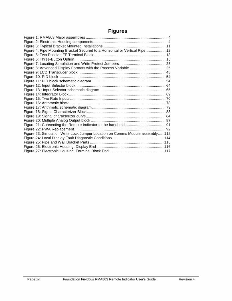
Figures Figure 1: RMA803 Major assemblies .............................................................................. 4 Figure 2: Electronic Housing components....................................................................... 4 Figure 3: Typical Bracket Mounted Installations............................................................ 11 Figure 4: Pipe Mounting Bracket Secured to a Horizontal or Vertical Pipe ................... 12 Figure 5: Two Position FF Terminal Block .................................................................... 13 Figure 6: Three-Button Option ....................................................................................... 15 Figure 7: Locating Simulation and Write Protect Jumpers ............................................ 23 Figure 8: Advanced Display Formats with the Process Variable .................................. 25 Figure 9: LCD Transducer block ................................................................................... 48 Figure 10: PID block ...................................................................................................... 54 Figure 11: PID block schematic diagram ....................................................................... 54 Figure 12: Input Selector block ...................................................................................... 64 Figure 13 : Input Selector schematic diagram ............................................................... 65 Figure 14: Integrator Block ............................................................................................ 69 Figure 15: Two Rate Inputs ........................................................................................... 70 Figure 16: Arithmetic block ............................................................................................ 78 Figure 17: Arithmetic schematic diagram ...................................................................... 79 Figure 18: Signal Characterizer Block ........................................................................... 83 Figure 19: Signal characterizer curve ............................................................................ 84 Figure 20: Multiple Analog Output block ....................................................................... 87 Figure 21: Connecting the Remote Indicator to the handheld ....................................... 91 Figure 22: PWA Replacement ....................................................................................... 92 Figure 23: Simulation Write Lock Jumper Location on Comms Module assembly ..... 112 Figure 24: Local Display Fault Diagnostic Conditions ................................................. 114 Figure 25: Pipe and Wall Bracket Parts ...................................................................... 115 Figure 26: Electronic Housing, Display End ................................................................ 116 Figure 27: Electronic Housing, Terminal Block End .................................................... 117

Revision 3 Foundation Fieldbus RMA803 Remote Indicator User's Guide Page 1
1. Introduction 1.1 About the RMA803 Remote Indicator
The Honeywell RMA803 is a Foundation Fieldbus Remote Indicator that provides the following benefits to the user:
Connectivity The RMA803 can be used with any Foundation Fieldbus device. The values from these Fieldbus devices can be connected to the RMA803 via the MAO function block (for example) and then sent to the LCD display via the LCD Transducer block. The RMA803 can display up to eight (8) values from the devices on the H1 segment.
Mounting The RMA803 can be connected anywhere along the H1 segment, providing easy access to data from devices that are mounted in inaccessible locations. The LCD module can be rotated in 90 degree increments, allowing the RMA803 to be mounted in any orientation.
Capacity The RMA803 can display up to eight (8) function block values. The RMA803 will automatically rotate through these values at a user-configurable rate. The user can also step through the values on-demand using the local pushbuttons.
LCD Display formats The RMA803 provides three user-friendly formats, including bar graph and trend. The scale limits of the bar graph and trend are configured by the user to allow optimum visibility of the process value. The trend format will plot the trend of the selected function block value. The duration of the trend is configured by the user, providing up to 24 hours of history for the selected value.
Custom labeling The user can enter a custom tag for each screen to provide clear identification of the displayed value. The user can also enter custom units for each screen, or select the units from a predefined list. The length of the custom tag is 14 characters; the length of the custom units label is 8 characters.
Additional calculation and control The RMA803 provides a robust set of function blocks that can be used to provide additional calculation and control capability.
Backup Link Active Scheduler (LAS) The RMA803 can also be configured as backup LAS, allowing the Fieldbus devices on the H1 segment to continue operating if the primary LAS fails.
Page 2 Foundation Fieldbus RMA803 Remote Indicator User's Guide Revision 4
Additional Function Blocks The RMA803 consists of two Application Software options, which are: • Standard Operating Software – Consists of Resource block, AI block, LCD Transducer block,
Diagnostic Transducer block, and MAO (Multiple Analog Output) function block • Additional Function Blocks – Consists of PID block, Signal Characterizer block, Arithmetic
block, Input Selector block and Integrator block. Refer to Section 7.5 for more details. Note: Additional Function blocks are available post liscensing.
Revision 4 Foundation Fieldbus RMA803 Remote Indicator User's Guide Page 3
1.2 Features and Options The RMA803 Foundation Fieldbus Remote Indicator has the following features:
Table 1: Feature and Options
Feature/Option Standard/Available Options
Communication Protocols Fieldbus and only Advanced Display
Human-Machine Interface (HMI) Options (Advanced Display)
Advanced Digital Display: 0, 90, 180, & 270 degree viewing position adjustments Standard and custom measurement units available. Up to eight display screens with 3 formats are possible (Large
PV or PV with Bar Graph or PV with Trend Graph) Configurable screen rotation timing (4 to 30 sec) Ability to enable/disable screen rotation
Three-button programming (optional)
Advanced display languages: East Asian: EN, CH, JP Western: EN, GE, FR, IT, SP, RU, TU
Approvals (See Appendix C for details.) ATEX, CSA, FM, IECx, NEPSI
Mounting Brackets Pipe mounting and wall mounting brackets in carbon steel and 316 stainless steel.
# of Devices/ Segments Entity IS model: 6 devices/segment
Schedule Entries 46 (max)
# of VCRs 50 (max), 50-link objects
Compliance Testing Tested according to ITK 6.1.1
Software Download Class-3 of the Common Software Download procedure as per FF-883.

Page 4 Foundation Fieldbus RMA803 Remote Indicator User's Guide Revision 4
1.3 RMA803 major assembly and electronic housing components
The following illustrations depict the major assembly and electronic housing components.
Figure 1: RMA803 Major assemblies
Figure 2: Electronic Housing components

Revision 4 Foundation Fieldbus RMA803 Remote Indicator User's Guide Page 5
1.4 Features of a Remote Indicator The Remote Indicator is a configurable intelligent field device which functions as an output and status indicator for any FF device. The core functionalities of the field device include: • Displaying Process Variable (PV) • Function Block Application Process (FBAP) • Device diagnostics The RMA803 features standard fieldbus function blocks with manufacturer-specific additions for enhanced operation. The Remote Indicator can function as a Link Active Scheduler (LAS) in a Fieldbus network. It supports the following features: • Link-master capability • Supports the following standard function blocks apart from the Resource and Transducer
blocks. − Input Selector block − AI block − Integrator block − Signal Characterizer block − PID with auto tune block − Arithmetic block − Multiple Analog Output Block
• Function block instantiation is supported by the following blocks − Input Selector block − PID block − Arithmetic block − Signal Characterizer block
• Supports the following Transducer blocks − LCD Transducer block − Diagnostic Transducer block
• Supports class 3 type firmware download through commercial hosts. DD and EDDL Features
The RMA803 supports DD and EDD file formats, and the data is displayed using the EDDL features in the form of menus, graphs, charts, and pictures.
Page 6 Foundation Fieldbus RMA803 Remote Indicator User's Guide Revision 4
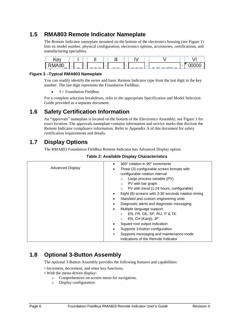
1.5 RMA803 Remote Indicator Nameplate The Remote Indicator nameplate mounted on the bottom of the electronics housing (see Figure 1) lists its model number, physical configuration, electronics options, accessories, certifications, and manufacturing specialties.
Figure 3 –Typical RMA803 Nameplate
You can readily identify the series and basic Remote Indicator type from the last digit in the key number. The last digit represents the Foundation Fieldbus.
• 3 = Foundation Fieldbus For a complete selection breakdown, refer to the appropriate Specification and Model Selection Guide provided as a separate document.
1.6 Safety Certification Information An “approvals” nameplate is located on the bottom of the Electronics Assembly; see Figure 1 for exact location. The approvals nameplate contains information and service marks that disclose the Remote Indicator compliance information. Refer to Appendix A of this document for safety certification requirements and details.
1.7 Display Options The RMA803 Foundation Fieldbus Remote Indicator has Advanced Display option.
Table 2: Available Display Characteristics
Advanced Display
• 360° rotation in 90° increments • Three (3) configurable screen formats with
configurable rotation interval o Large process variable (PV) o PV with bar graph o PV with trend (1-24 hours, configurable)
• Eight (8) screens with 3-30 seconds rotation timing • Standard and custom engineering units • Diagnostic alerts and diagnostic messaging • Multiple language support:
o EN, FR, GE, SP, RU, IT & TK o EN, CH (Kanji), JP
• Square root output indication • Supports 3-button configuration • Supports messaging and maintenance mode
indications of the Remote Indicator
1.8 Optional 3-Button Assembly The optional 3-Button Assembly provides the following features and capabilities: • Increment, decrement, and enter key functions. • With the menu-driven display:
o Comprehensive on-screen menu for navigation. o Display configuration.
Revision 4 Foundation Fieldbus RMA803 Remote Indicator User's Guide Page 7
2. Getting started
2.1 Verifying the installation Verifying Remote Indicator installation tasks
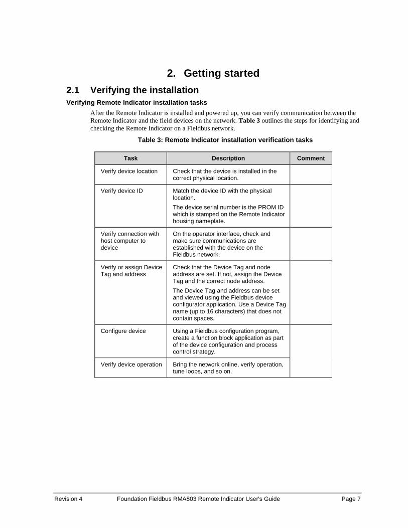
After the Remote Indicator is installed and powered up, you can verify communication between the Remote Indicator and the field devices on the network. Table 3 outlines the steps for identifying and checking the Remote Indicator on a Fieldbus network.
Table 3: Remote Indicator installation verification tasks
Task Description Comment
Verify device location Check that the device is installed in the correct physical location.
Verify device ID Match the device ID with the physical location. The device serial number is the PROM ID which is stamped on the Remote Indicator housing nameplate.
Verify connection with host computer to device
On the operator interface, check and make sure communications are established with the device on the Fieldbus network.
Verify or assign Device Tag and address
Check that the Device Tag and node address are set. If not, assign the Device Tag and the correct node address. The Device Tag and address can be set and viewed using the Fieldbus device configurator application. Use a Device Tag name (up to 16 characters) that does not contain spaces.
Configure device Using a Fieldbus configuration program, create a function block application as part of the device configuration and process control strategy.
Verify device operation Bring the network online, verify operation, tune loops, and so on.
Page 8 Foundation Fieldbus RMA803 Remote Indicator User's Guide Revision 4
2.2 Verifying communication with the Remote Indicator On the operator interface, establish communication with the device on the Fieldbus network. If the device is not visible on the network, verify that the device has been installed properly.
Identify the Remote Indicator Verify the Device ID of the Remote Indicator by checking the device parameters. The parameters contain the following information:
• Device Tag (tag description of the Remote Indicator) • Device Serial number • Firmware revision level (revision level of the firmware elements)
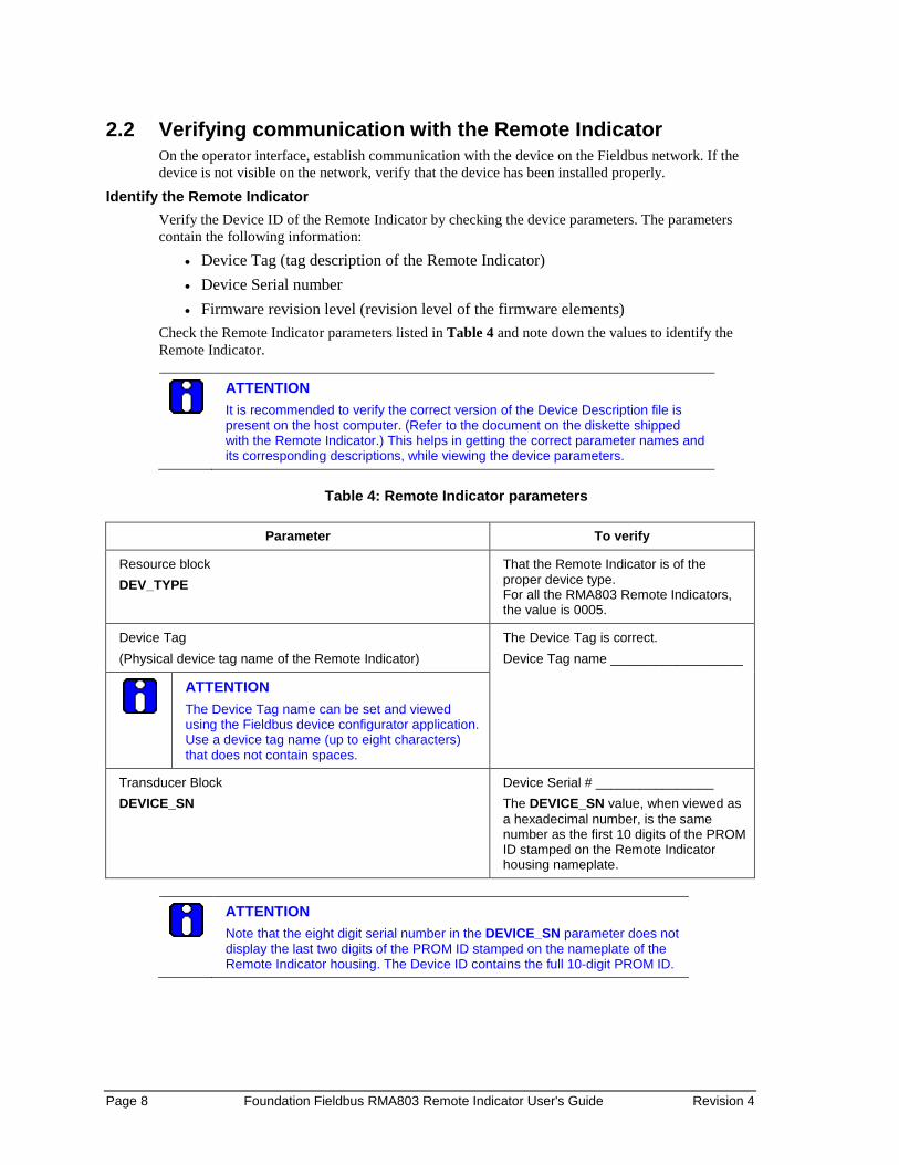
Check the Remote Indicator parameters listed in Table 4 and note down the values to identify the Remote Indicator.
ATTENTION It is recommended to verify the correct version of the Device Description file is present on the host computer. (Refer to the document on the diskette shipped with the Remote Indicator.) This helps in getting the correct parameter names and its corresponding descriptions, while viewing the device parameters.
Table 4: Remote Indicator parameters
Parameter To verify
Resource block DEV_TYPE
That the Remote Indicator is of the proper device type. For all the RMA803 Remote Indicators, the value is 0005.
Device Tag (Physical device tag name of the Remote Indicator)
The Device Tag is correct. Device Tag name __________________
ATTENTION The Device Tag name can be set and viewed using the Fieldbus device configurator application. Use a device tag name (up to eight characters) that does not contain spaces.
Transducer Block DEVICE_SN
Device Serial # ________________ The DEVICE_SN value, when viewed as a hexadecimal number, is the same number as the first 10 digits of the PROM ID stamped on the Remote Indicator housing nameplate.
ATTENTION Note that the eight digit serial number in the DEVICE_SN parameter does not display the last two digits of the PROM ID stamped on the nameplate of the Remote Indicator housing. The Device ID contains the full 10-digit PROM ID.
Revision 4 Foundation Fieldbus RMA803 Remote Indicator User's Guide Page 9
2.3 Establishing communication with host systems The RMA803 Remote Indicator establishes communication with the host systems using a DD or DTM.
Device Description (DD) DD is a binary file that provides the definition for parameters in the FBAP of the RMA803 Remote Indicator. For example, DD refers to the function blocks that a Remote Indicator contains, and the corresponding parameters in the blocks that are critical to the interoperability of Fieldbus devices. They define the data required to establish communications between different Fieldbus devices from multiple vendors with control system hosts. The DD provides an extended description of each object in the Virtual Field Device (VFD). The Fieldbus Foundation provides the DD for all standard function blocks and transducer blocks on a CD-ROM. The Fieldbus Foundation also provides this information on its website, www.fieldbus.org.
Enhanced Device Description (EDD) There are two types of EDDs are available, namely .ff5/.sy5 and .ffo/sym. The.ffo/.sym binary files are generated for the legacy hosts to load the device DD that is generated using latest tokenizer. Few constructs like Images that are supported in .ff5/.sy5 binaries, are not supported in .ffo/.sym binary files.
Device Type Manager (DTM) DTM is similar to a device driver that enables usage of devices in all the asset management and device configuration software like FDM, with the help of the FDT-DTM technology. The DTM has the following primary functions: • Provides a graphic user interface for device configuration. • Provides device configuration, calibration, and management features for the particular device. DTM provides functions for accessing device parameters, configuring and operating the devices, calibrating, and diagnosing problems.

Page 10 Foundation Fieldbus RMA803 Remote Indicator User's Guide Revision 4
This page is left blank intentionally.

Revision 4 Foundation Fieldbus RMA803 Remote Indicator User's Guide Page 11
3. Installation and Startup 3.1 Installation Site Evaluation
Evaluate the site selected for the Remote Indicator installation with respect to the process system design specifications and Honeywell’s published performance characteristics for your particular model. Some parameters that you may want to include in your site evaluation are: • Environmental Conditions:
o Ambient Temperature o Relative Humidity
• Potential Noise Sources: o Radio Frequency Interference (RFI) o Electromagnetic Interference (EMI)
• Vibration Sources o Motorized System Devices (e.g., pumps) o Valve Cavitation
• Process Parameters o Temperature o Maximum Pressure Rating
3.2 Display Installation Precautions Temperature extremes can affect display quality. The display can go blank if the temperature is below -20°C; however, this is only a temporary condition. The display will again be readable when temperatures return to within operable limits. The display update rate may increase at cold temperature extremes, but as with readability, normal updating resumes when temperatures are within limits for full operability.
3.3 Mounting Remote Indicator Summary
Remote Indicator models can be attached to a two-inch (50 millimeter) vertical or horizontal pipe using Honeywell’s optional pipe mounting bracket. Honeywell’s optional wall mounting bracket is also shown below. Figure 3 shows typical bracket-mounted installations.
Figure 3: Typical Bracket Mounted Installations
Page 12 Foundation Fieldbus RMA803 Remote Indicator User's Guide Revision 4
Mounting Dimensions Refer to Honeywell drawing number 51455045* for detailed electronic housing dimensions. Refer to Honeywell drawing numbers 32306827* for detailed pipe mounting dimensions and 50124813* for detailed wall mounting dimensions. Abbreviated overall dimensions are also shown on the Specification Sheets for the Remote Indicator models. This section assumes that the mounting dimensions have already been taken into account and the mounting area can accommodate the Remote Indicator.
* Honeywell drawings can be supplied on request.
Bracket Mounting Procedure 1. Align the two mounting holes in the Remote Indicator with the two slots in the mounting bracket
and assemble the (2) M8 hex cap screws, (2) lockwashers and (2) flat washers provided. Rotate Remote Indicator assembly to the desired position and torque the M8 hex cap screws to 27,0 Nm/20,0 Lb-ft maximum.
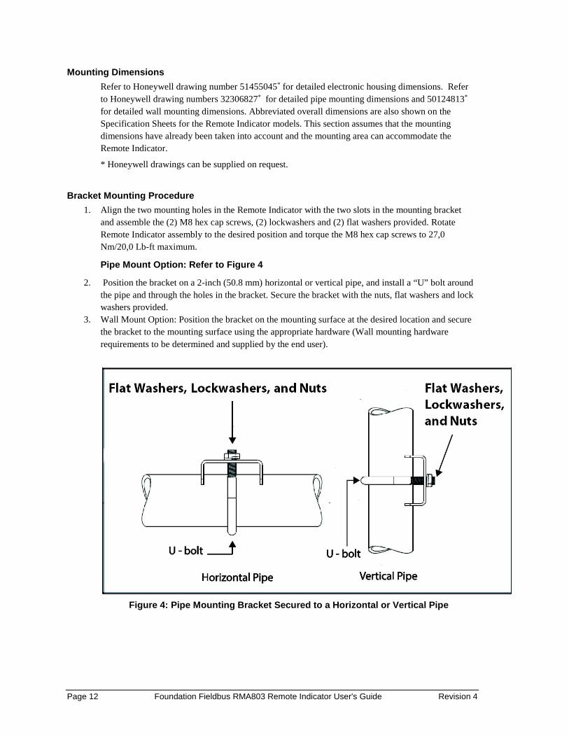
Pipe Mount Option: Refer to Figure 4
2. Position the bracket on a 2-inch (50.8 mm) horizontal or vertical pipe, and install a “U” bolt around the pipe and through the holes in the bracket. Secure the bracket with the nuts, flat washers and lock washers provided.
3. Wall Mount Option: Position the bracket on the mounting surface at the desired location and secure the bracket to the mounting surface using the appropriate hardware (Wall mounting hardware requirements to be determined and supplied by the end user).
Figure 4: Pipe Mounting Bracket Secured to a Horizontal or Vertical Pipe
Revision 4 Foundation Fieldbus RMA803 Remote Indicator User's Guide Page 13
3.4 Wiring a Remote Indicator Overview
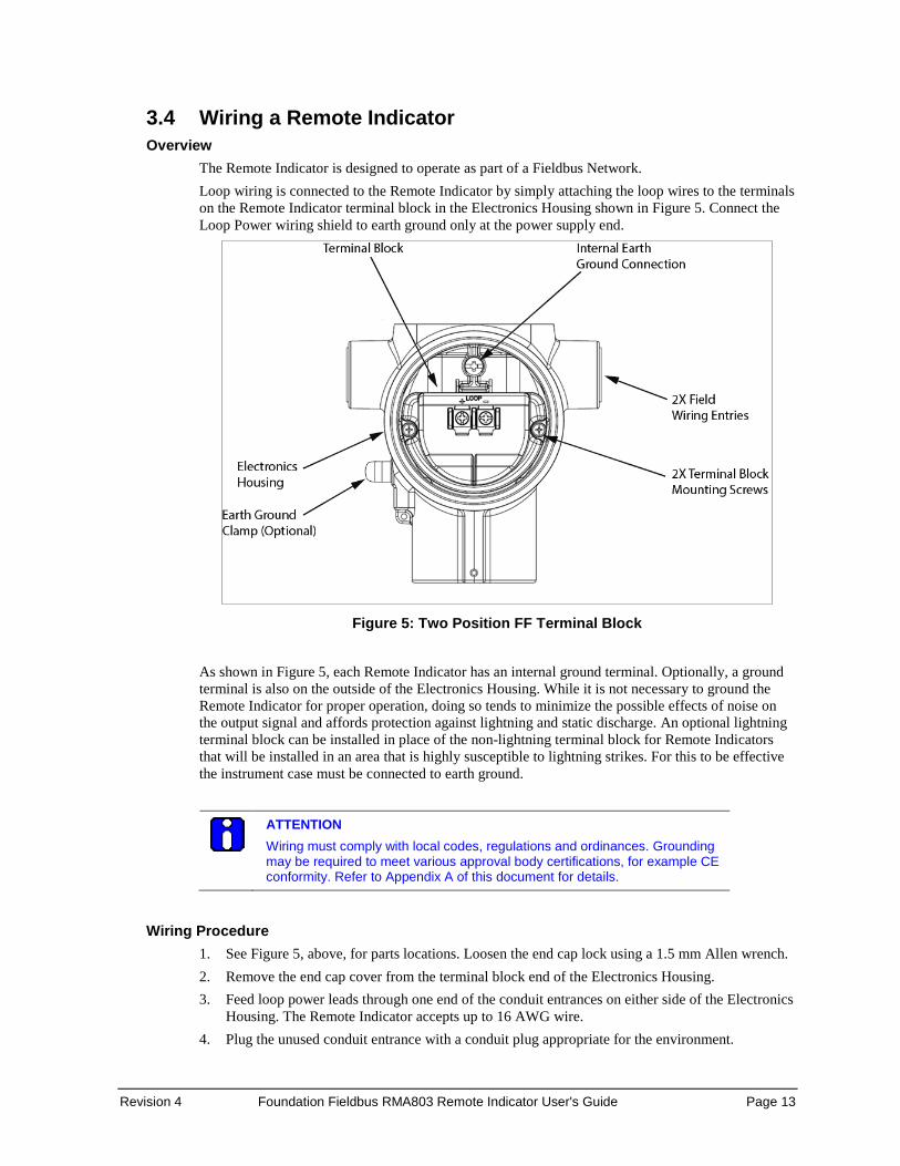
The Remote Indicator is designed to operate as part of a Fieldbus Network. Loop wiring is connected to the Remote Indicator by simply attaching the loop wires to the terminals on the Remote Indicator terminal block in the Electronics Housing shown in Figure 5. Connect the Loop Power wiring shield to earth ground only at the power supply end.
Figure 5: Two Position FF Terminal Block
As shown in Figure 5, each Remote Indicator has an internal ground terminal. Optionally, a ground terminal is also on the outside of the Electronics Housing. While it is not necessary to ground the Remote Indicator for proper operation, doing so tends to minimize the possible effects of noise on the output signal and affords protection against lightning and static discharge. An optional lightning terminal block can be installed in place of the non-lightning terminal block for Remote Indicators that will be installed in an area that is highly susceptible to lightning strikes. For this to be effective the instrument case must be connected to earth ground.
ATTENTION Wiring must comply with local codes, regulations and ordinances. Grounding may be required to meet various approval body certifications, for example CE conformity. Refer to Appendix A of this document for details.
Wiring Procedure
1. See Figure 5, above, for parts locations. Loosen the end cap lock using a 1.5 mm Allen wrench. 2. Remove the end cap cover from the terminal block end of the Electronics Housing. 3. Feed loop power leads through one end of the conduit entrances on either side of the Electronics
Housing. The Remote Indicator accepts up to 16 AWG wire. 4. Plug the unused conduit entrance with a conduit plug appropriate for the environment.
Page 14 Foundation Fieldbus RMA803 Remote Indicator User's Guide Revision 4
5. Feed both loop powered leads through the Ferrite core, 32301350-001, and then back around and through a second time.
6. Connect both loop power leads to the loop terminals. Torque terminal screws to 0,6 N.m (5.3 lbf.in) to 0.8 N.m (7.0 lbf.in). Note. The remote Indicator is not polarity-sensitive.
7. Replace the end cap and secure it in place being careful not to damage the ferrite core or wires. Fieldbus Network Wiring
For Fieldbus network wiring concepts see application notes such as Relcom Inc. Fieldbus Wiring Guide.
Lightning Protection
If your Remote Indicator includes the optional lightning protection, connect a wire from the Earth Ground Clamp (see Figure 5) to Earth Ground to make the protection effective. Use a size 8 AWG or (8.37mm2) bare or green covered wire for this connection.
Supply Voltage Limiting Requirements
If your Remote Indicator complies with the ATEX 4 directive for self-declared approval per 94/9EC, the power supply has to include a voltage-limiting device. Voltage must be limited such that it does not exceed 9 to 32 V DC. Consult the process design system documentation for specifics.
ATTENTION FF power Supply along with the Terminators has to be used.
Explosion-Proof Conduit Seal
WARNING When installed as explosion proof in a Division 1 Hazardous Location, keep covers tight while the Remote Indicator is energized. Disconnect power to the Remote Indicator in the non-hazardous area prior to removing end caps for service. When installed as non-incendive equipment in a Division 2 hazardous location, disconnect power to the Remote Indicator in the non-hazardous area, or determine that the location is non-hazardous before disconnecting or connecting the Remote Indicator wires.
Remote Indicator installed as explosion proof in Class I, Division 1, Group A Hazardous (classified) locations in accordance with ANSI/NFPA 70, the US National Electrical Code, with 1/2 inch conduit do not require an explosion-proof seal for installation. If 3/4 inch conduit is used, a LISTED explosion proof seal must be installed in the conduit, within 18 inches (457.2 mm) of the Remote Indicator.
Revision 4 Foundation Fieldbus RMA803 Remote Indicator User's Guide Page 15
4. Operation
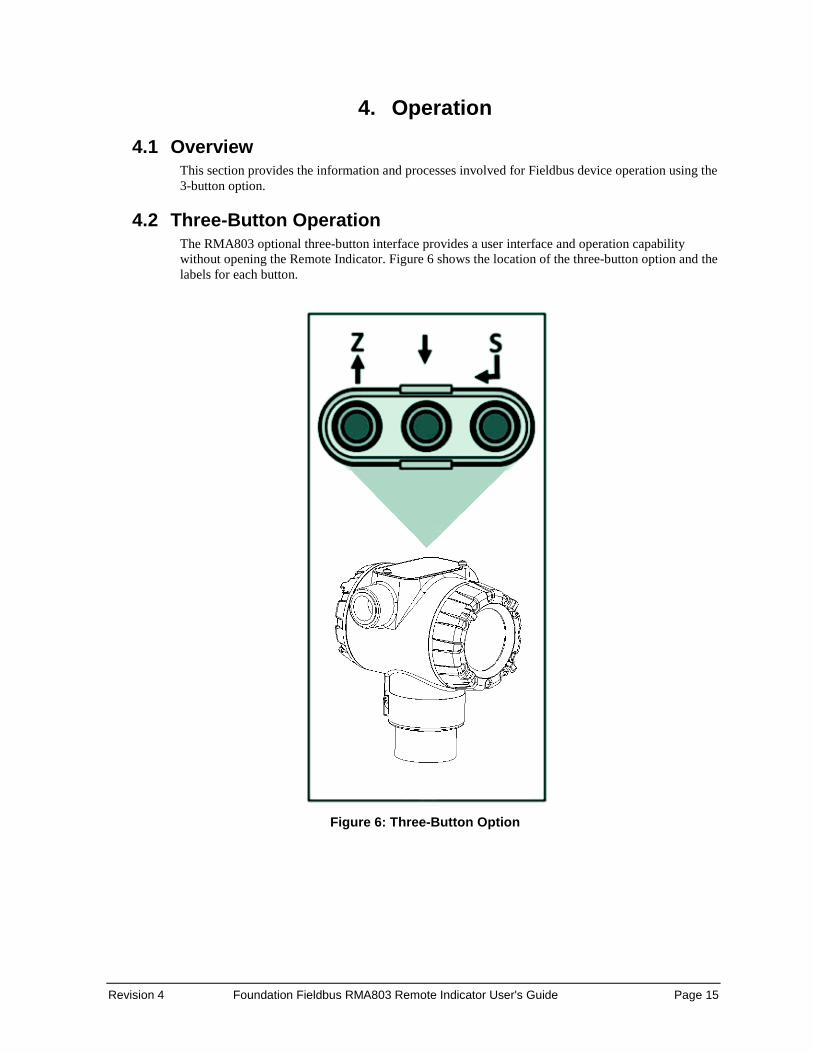
4.1 Overview This section provides the information and processes involved for Fieldbus device operation using the 3-button option.
4.2 Three-Button Operation The RMA803 optional three-button interface provides a user interface and operation capability without opening the Remote Indicator. Figure 6 shows the location of the three-button option and the labels for each button.
Figure 6: Three-Button Option
Page 16 Foundation Fieldbus RMA803 Remote Indicator User's Guide Revision 4
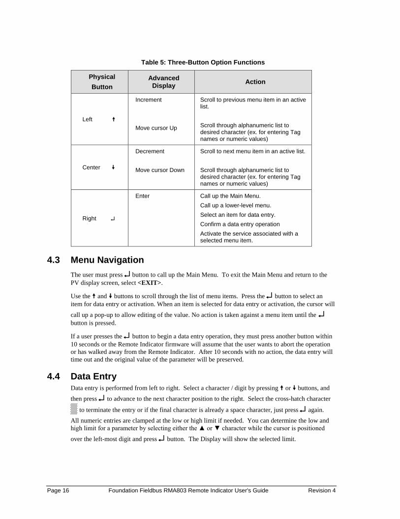
Table 5: Three-Button Option Functions
Physical Button
Advanced Display Action
Left
Increment Move cursor Up
Scroll to previous menu item in an active list. Scroll through alphanumeric list to desired character (ex. for entering Tag names or numeric values)
Center
Decrement Move cursor Down
Scroll to next menu item in an active list. Scroll through alphanumeric list to desired character (ex. for entering Tag names or numeric values)
Right ↵
Enter Call up the Main Menu. Call up a lower-level menu. Select an item for data entry. Confirm a data entry operation Activate the service associated with a selected menu item.
4.3 Menu Navigation The user must press ↵ button to call up the Main Menu. To exit the Main Menu and return to the PV display screen, select <EXIT>.
Use the and buttons to scroll through the list of menu items. Press the ↵ button to select an item for data entry or activation. When an item is selected for data entry or activation, the cursor will call up a pop-up to allow editing of the value. No action is taken against a menu item until the ↵ button is pressed.
If a user presses the ↵ button to begin a data entry operation, they must press another button within 10 seconds or the Remote Indicator firmware will assume that the user wants to abort the operation or has walked away from the Remote Indicator. After 10 seconds with no action, the data entry will time out and the original value of the parameter will be preserved.
4.4 Data Entry Data entry is performed from left to right. Select a character / digit by pressing or buttons, and then press ↵ to advance to the next character position to the right. Select the cross-hatch character
▒ to terminate the entry or if the final character is already a space character, just press ↵ again. All numeric entries are clamped at the low or high limit if needed. You can determine the low and high limit for a parameter by selecting either the ▲ or ▼ character while the cursor is positioned
over the left-most digit and press ↵ button. The Display will show the selected limit.
Revision 4 Foundation Fieldbus RMA803 Remote Indicator User's Guide Page 17
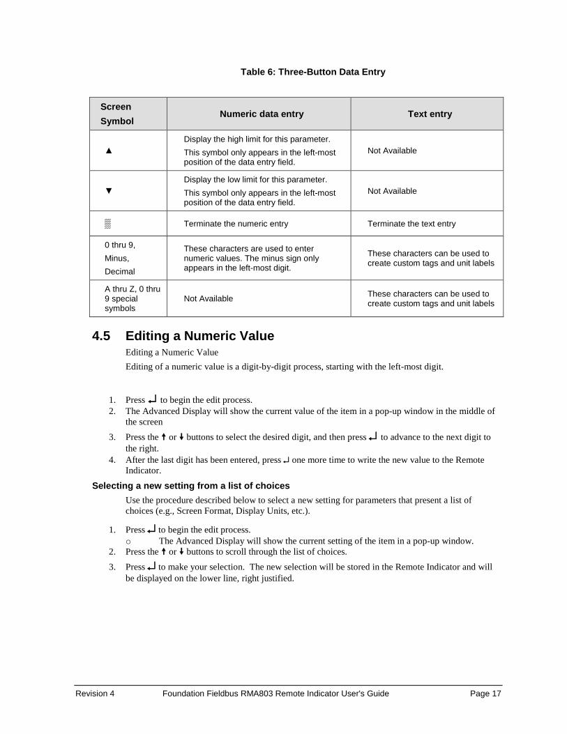
Table 6: Three-Button Data Entry
Screen Symbol
Numeric data entry Text entry
▲ Display the high limit for this parameter. This symbol only appears in the left-most position of the data entry field.
Not Available
▼ Display the low limit for this parameter. This symbol only appears in the left-most position of the data entry field.
Not Available
▒ Terminate the numeric entry Terminate the text entry
0 thru 9, Minus, Decimal
These characters are used to enter numeric values. The minus sign only appears in the left-most digit.
These characters can be used to create custom tags and unit labels
A thru Z, 0 thru 9 special symbols
Not Available These characters can be used to create custom tags and unit labels
4.5 Editing a Numeric Value Editing a Numeric Value Editing of a numeric value is a digit-by-digit process, starting with the left-most digit.
1. Press ↵ to begin the edit process. 2. The Advanced Display will show the current value of the item in a pop-up window in the middle of
the screen 3. Press the or buttons to select the desired digit, and then press ↵ to advance to the next digit to
the right. 4. After the last digit has been entered, press ↵ one more time to write the new value to the Remote
Indicator.
Selecting a new setting from a list of choices Use the procedure described below to select a new setting for parameters that present a list of choices (e.g., Screen Format, Display Units, etc.).
1. Press ↵ to begin the edit process. o The Advanced Display will show the current setting of the item in a pop-up window.
2. Press the or buttons to scroll through the list of choices. 3. Press ↵ to make your selection. The new selection will be stored in the Remote Indicator and will
be displayed on the lower line, right justified.
Page 18 Foundation Fieldbus RMA803 Remote Indicator User's Guide Revision 4
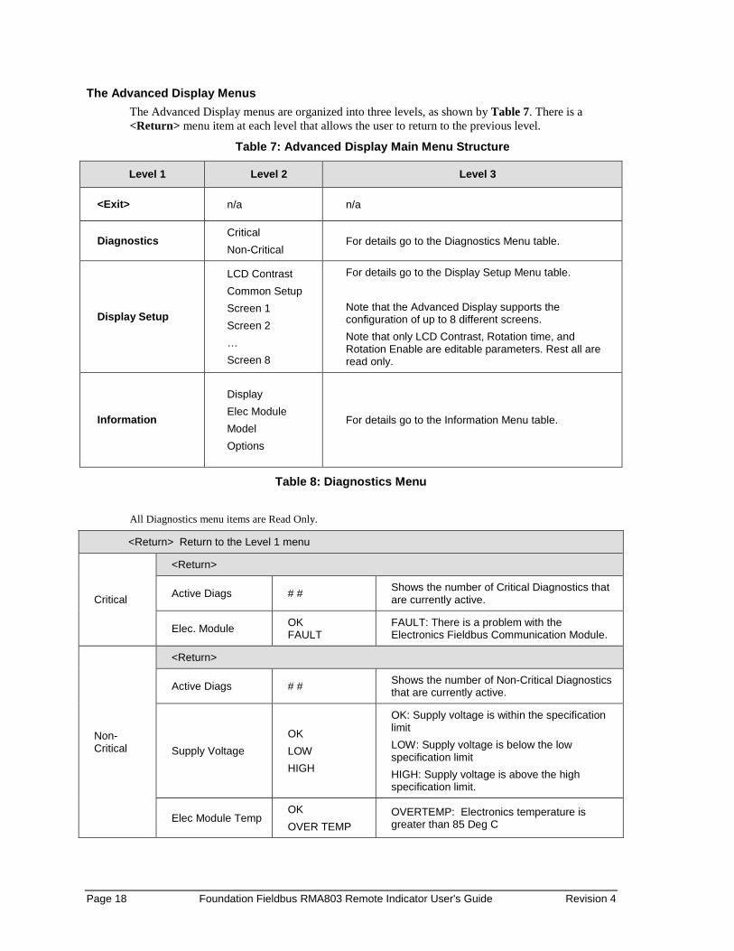
The Advanced Display Menus The Advanced Display menus are organized into three levels, as shown by Table 7. There is a <Return> menu item at each level that allows the user to return to the previous level.
Table 7: Advanced Display Main Menu Structure
Level 1 Level 2 Level 3
<Exit> n/a n/a
Diagnostics Critical Non-Critical
For details go to the Diagnostics Menu table.
Display Setup
LCD Contrast Common Setup Screen 1 Screen 2 … Screen 8
For details go to the Display Setup Menu table. Note that the Advanced Display supports the configuration of up to 8 different screens. Note that only LCD Contrast, Rotation time, and Rotation Enable are editable parameters. Rest all are read only.
Information
Display Elec Module Model Options
For details go to the Information Menu table.
Table 8: Diagnostics Menu All Diagnostics menu items are Read Only.
<Return> Return to the Level 1 menu
Critical
<Return>
Active Diags # # Shows the number of Critical Diagnostics that are currently active.
Elec. Module OK FAULT
FAULT: There is a problem with the Electronics Fieldbus Communication Module.
Non-Critical
<Return>
Active Diags # # Shows the number of Non-Critical Diagnostics that are currently active.
Supply Voltage OK LOW HIGH
OK: Supply voltage is within the specification limit LOW: Supply voltage is below the low specification limit HIGH: Supply voltage is above the high specification limit.
Elec Module Temp OK OVER TEMP
OVERTEMP: Electronics temperature is greater than 85 Deg C

Revision 4 Foundation Fieldbus RMA803 Remote Indicator User's Guide Page 19
Table 9: Display Setup Menus
<Return> Return to the Level 1 menu
LCD Contrast
<Return>
Set Contrast # #
Adjust the LCD contrast level. Range from 1 to 9. Default: 5
Press ↵ to enter menu selection ↑ and ↓ to select number. ↵ to enter and shift to next digit
Common Setup
<Return>
Language
English, French, German, Spanish, Russian, Chinese, Japanese, Turkish, and Italian
Shows the selected language. Default: English
Read Only
Rotation Time # #
Time duration, in seconds, that each configured screen is shown before moving to the next screen. Range: 3 to 30 seconds Default: 10 seconds
Press ↵ to enter menu selection ↑ and ↓ to select number. ↵ to enter and shift to next digit
Rotation Enable Yes, No
Option Yes or No enables or disables the screen rotation
Press ↵ to enter menu selection ↑ and ↓ to select Enable or Disable. ↵ to enter and shift to next digit
Screens 1 thru 8
<Return>
Screen Format
None
Shows the selected format. Read Only
PV
PV & Bar Graph
PV & Trend
Trend Duration ## Shows the selected Trend duration from the host.
Read Only
Page 20 Foundation Fieldbus RMA803 Remote Indicator User's Guide Revision 4
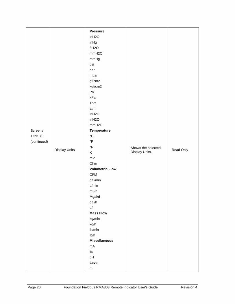
Screens 1 thru 8 (continued)
Display Units
Pressure inH2O inHg ftH2O mmH2O mmHg psi bar mbar gf/cm2 kgf/cm2 Pa kPa Torr atm inH2O inH2O mmH2O Temperature °C °F °R K mV Ohm Volumetric Flow CFM gal/min L/min m3/h Mgal/d gal/h L/h Mass Flow kg/min kg/h lb/min lb/h Miscellaneous mA % pH Level m
Shows the selected Display Units. Read Only
Revision 4 Foundation Fieldbus RMA803 Remote Indicator User's Guide Page 21
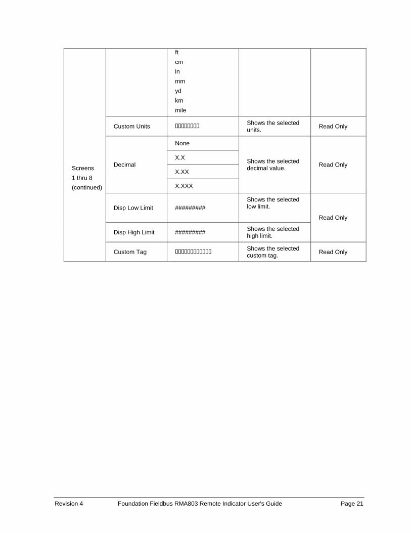
Screens 1 thru 8 (continued)
ft cm in mm yd km mile
Custom Units �������� Shows the selected units. Read Only
Decimal
None
Shows the selected decimal value. Read Only
X.X
X.XX
X.XXX
Disp Low Limit ######### Shows the selected low limit. Read Only
Disp High Limit ######### Shows the selected high limit.
Custom Tag ������������ Shows the selected custom tag. Read Only
Page 22 Foundation Fieldbus RMA803 Remote Indicator User's Guide Revision 4
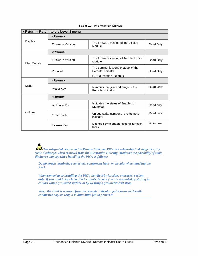
Table 10: Information Menus
<Return> Return to the Level 1 menu
Display <Return>
Firmware Version The firmware version of the Display Module Read Only
Elec Module
<Return>
Firmware Version The firmware version of the Electronics Module Read Only
Protocol The communications protocol of the Remote Indicator:
FF: Foundation Fieldbus Read Only
Model
<Return>
Model Key Identifies the type and range of the Remote Indicator
Read Only
Options
<Return>
Additional FB Indicates the status of Enabled or Disabled Read only
Serial Number Unique serial number of the Remote indicator
Read only
License Key License key to enable optional function block
Write only
The integrated circuits in the Remote Indicator PWA are vulnerable to damage by stray static discharges when removed from the Electronics Housing. Minimize the possibility of static discharge damage when handling the PWA as follows:
Do not touch terminals, connectors, component leads, or circuits when handling the PWA.
When removing or installing the PWA, handle it by its edges or bracket section only. If you need to touch the PWA circuits, be sure you are grounded by staying in contact with a grounded surface or by wearing a grounded wrist strap.
When the PWA is removed from the Remote Indicator, put it in an electrically conductive bag, or wrap it in aluminum foil to protect it.

Revision 4 Foundation Fieldbus RMA803 Remote Indicator User's Guide Page 23
The following procedure outlines the steps for positioning the write protect and failsafe jumpers on the electronics module. See Figure 7 for the locations of the failsafe and write protect jumpers.
Figure 7: Locating Simulation and Write Protect Jumpers
Page 24 Foundation Fieldbus RMA803 Remote Indicator User's Guide Revision 4
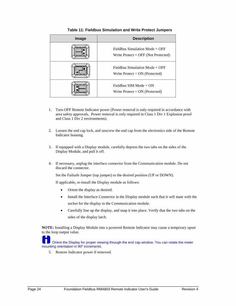
Table 11: Fieldbus Simulation and Write Protect Jumpers
Image Description
Fieldbus Simulation Mode = OFF Write Protect = OFF (Not Protected)
Fieldbus Simulation Mode = OFF Write Protect = ON (Protected)
Fieldbus SIM Mode = ON Write Protect = ON (Protected)
1. Turn OFF Remote Indicator power (Power removal is only required in accordance with area safety approvals. Power removal is only required in Class 1 Div 1 Explosion proof and Class 1 Div 2 environments).
2. Loosen the end cap lock, and unscrew the end cap from the electronics side of the Remote
Indicator housing.
3. If equipped with a Display module, carefully depress the two tabs on the sides of the Display Module, and pull it off.
4. If necessary, unplug the interface connector from the Communication module. Do not
discard the connector.
Set the Failsafe Jumper (top jumper) to the desired position (UP or DOWN).
If applicable, re-install the Display module as follows:
• Orient the display as desired.
• Install the Interface Connector in the Display module such that it will mate with the
socket for the display in the Communication module.
• Carefully line up the display, and snap it into place. Verify that the two tabs on the
sides of the display latch.
NOTE: Installing a Display Module into a powered Remote Indicator may cause a temporary upset to the loop output value.
Orient the Display for proper viewing through the end cap window. You can rotate the meter mounting orientation in 90o increments.
5. Restore Indicator power if removed.

Revision 4 Foundation Fieldbus RMA803 Remote Indicator User's Guide Page 25
4.6 Advanced Displays As shown in Figure 8, the Advanced Display provides three formats. Figure 8 lists and describes the fields in each of the three Advanced Display formats. Essentially, all three formats provide the same information, but with the following differences:
• Bar Graph. User Configurable 126 segment Bar Graph with range settings. The Bar Graph displays the current value of the configured PV.
• PV Trend. User-configurable display period from one hour to 24 hours. The chart displays minimum, maximum, and average of the configured PV over the selected trend period.
Figure 8: Advanced Display Formats with the Process Variable
Page 26 Foundation Fieldbus RMA803 Remote Indicator User's Guide Revision 4
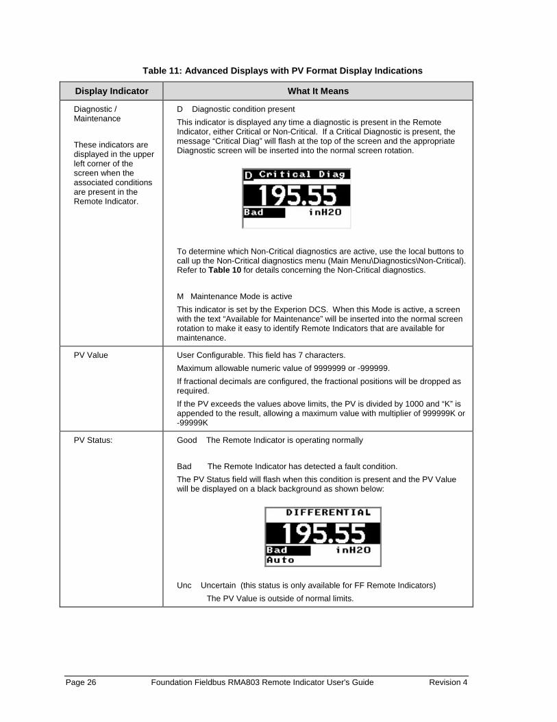
Table 11: Advanced Displays with PV Format Display Indications
Display Indicator What It Means
Diagnostic / Maintenance These indicators are displayed in the upper left corner of the screen when the associated conditions are present in the Remote Indicator.
D Diagnostic condition present This indicator is displayed any time a diagnostic is present in the Remote Indicator, either Critical or Non-Critical. If a Critical Diagnostic is present, the message “Critical Diag” will flash at the top of the screen and the appropriate Diagnostic screen will be inserted into the normal screen rotation.
To determine which Non-Critical diagnostics are active, use the local buttons to call up the Non-Critical diagnostics menu (Main Menu\Diagnostics\Non-Critical). Refer to Table 10 for details concerning the Non-Critical diagnostics. M Maintenance Mode is active This indicator is set by the Experion DCS. When this Mode is active, a screen with the text “Available for Maintenance” will be inserted into the normal screen rotation to make it easy to identify Remote Indicators that are available for maintenance.
PV Value User Configurable. This field has 7 characters. Maximum allowable numeric value of 9999999 or -999999. If fractional decimals are configured, the fractional positions will be dropped as required. If the PV exceeds the values above limits, the PV is divided by 1000 and “K” is appended to the result, allowing a maximum value with multiplier of 999999K or -99999K
PV Status: Good The Remote Indicator is operating normally Bad The Remote Indicator has detected a fault condition. The PV Status field will flash when this condition is present and the PV Value will be displayed on a black background as shown below:
Unc Uncertain (this status is only available for FF Remote Indicators) The PV Value is outside of normal limits.

Revision 4 Foundation Fieldbus RMA803 Remote Indicator User's Guide Page 27
PV Function Block Mode
The Function Block Mode is only displayed for Foundation Fieldbus Remote Indicators. The eight possible Modes are shown below.
OOS Out Of Service Auto Automatic Man Manual Cas Cascade
RCas Remote Cascade Rout Remote Output IMan Initialization Manual LO Local Override
Process Variable Tag User Configurable. This field has 14 characters
PV Units User Configurable. This field has 8 characters
Pressure: inH2O inHg ftH2O mmH2O mmHg psi bar mbar gf/cm2 kgf/cm2 Pa kPa Torr atm inH2O inH2O mmH2O
Level: m ft cm in mm yd km mile
Temperature: o C o F o R K mV ohm
Mass Flow: kg/min kg/h lb/min lb/h Volumetric Flow: CFM gal/min L/min m3/h Mgal/d gal/h L/h Miscellaneous: mA % pH
Bar Graph The limits of the bar graph are user-configurable for each screen.
Trend graph The limits of the trend graph are user-configurable for each screen. The amount of time visible on the Trend graph is also configurable.
Button operation during monitoring When the operator screens are active on the Advanced Display, the Increment and Decrement
buttons ( and ) can be used to move to the next or previous operator screen without waiting for the
rotation time to expire. Pressing the Enter button ( ↵ ) will call up the Main Menu.
Page 28 Foundation Fieldbus RMA803 Remote Indicator User's Guide Revision 4
5. RMA803 FF Remote Indicator Configuration
ATTENTION Additional Function blocks are available post liscensing.
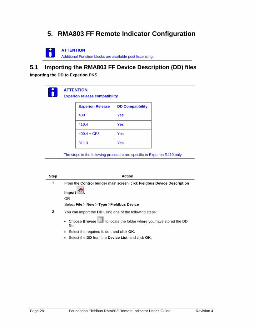
5.1 Importing the RMA803 FF Device Description (DD) files Importing the DD to Experion PKS
ATTENTION Experion release compatibility
Experion Release DD Compatibility
430 Yes
410.4 Yes
400.4 + CP3 Yes
311.3 Yes The steps in the following procedure are specific to Experion R410 only.
Step Action
1 From the Control builder main screen, click Fieldbus Device Description
Import . OR Select File > New > Type >Fieldbus Device
2 You can Import the DD using one of the following steps:
• Choose Browse to locate the folder where you have stored the DD file.
• Select the required folder, and click OK. • Select the DD from the Device List, and click OK.
Revision 4 Foundation Fieldbus RMA803 Remote Indicator User's Guide Page 29
Step Action
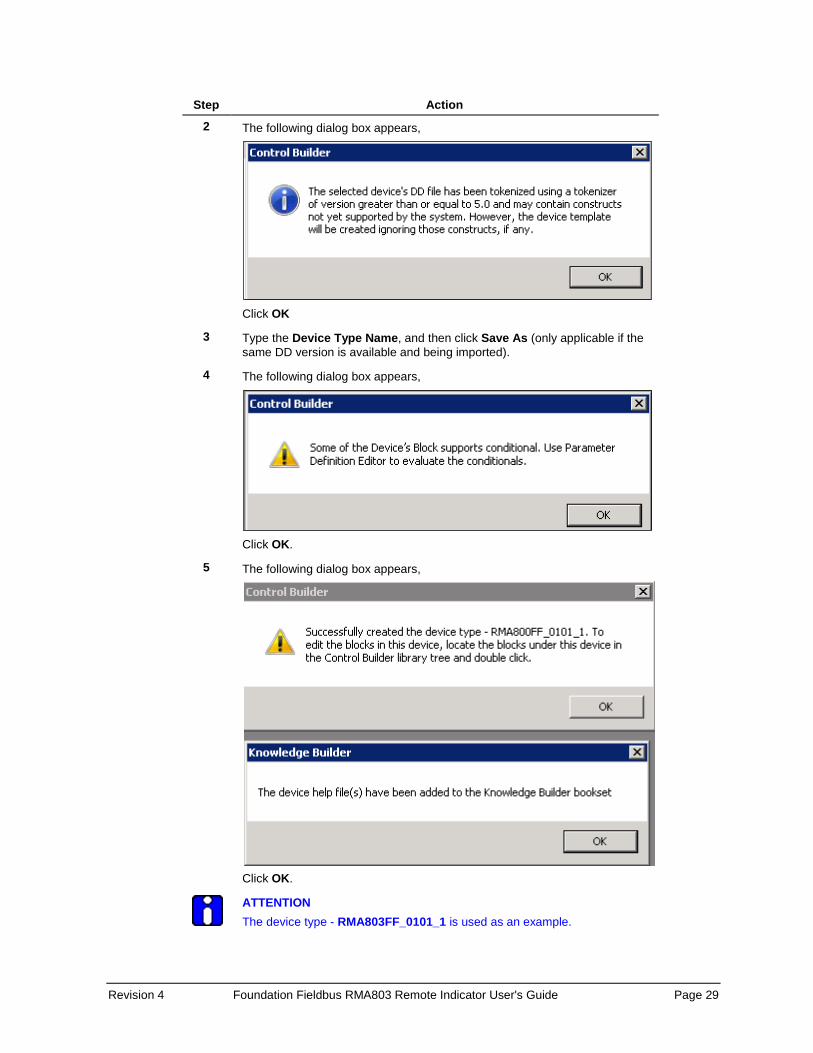
2 The following dialog box appears,
Click OK
3 Type the Device Type Name, and then click Save As (only applicable if the same DD version is available and being imported).
4 The following dialog box appears,
Click OK.
5 The following dialog box appears,
Click OK.
ATTENTION The device type - RMA803FF_0101_1 is used as an example.

Page 30 Foundation Fieldbus RMA803 Remote Indicator User's Guide Revision 4
6 The device is created in the Library-Containment window under the folder named Honeywell.
7 From the Library-Containment window, drag and drop the device into the corresponding FF link on the Project-Assignment window.
8 You are prompted to name the new function block. If you want to change the name in the destination column, type the new name or if you want to use the default name, click Finish. The device is added on the FF link on the Project-Assignment window. A series of steps for commissioning the device has to be followed in each type of DCS.
9 Right-click the new device and then click Load.
10 The following WARNING appears.
Click Continue.
11 The following dialog box appears,
Select the Automatically change ALL control elements to the state selected in “Post Load State” after load is completed checkbox and click OK.

Revision 4 Foundation Fieldbus RMA803 Remote Indicator User's Guide Page 31
12 On the Monitoring-Assignment window, you can notice that device on the Project-Assignment window has been loaded to the corresponding FF link.
13 Right-click the device, and then click Activate >> Selected Item(s) and Content(s). The device is commissioned.
ATTENTION Note that after importing the DD, you have to create control strategies.
Control strategy A control strategy is an organized approach to define a specific process using detailed information to: • create control modules in an associated controlled environment • configure function blocks to enable control applications, and • runs in a control software infrastructure To build a control strategy, a Control Module (CM) must be created where function blocks are inserted and connected with other function blocks.
Creating control strategy For information on creating control strategy, refer to the corresponding DCS document.

Page 32 Foundation Fieldbus RMA803 Remote Indicator User's Guide Revision 4
5.2 Configuring the function block application process About the Function Block Application Process (FBAP)
The RMA803 Remote Indicator has one resource block, two transducer blocks, and seven function blocks respectively. The DD-View feature supports all the 9 permanent blocks. The FBAP provides the block related information in a much more organized way. The FBAP defines blocks to represent different types of application functions. In addition, the blocks have a static revision parameter. The revision level of the static data is associated with the function block. To support tracking changes in static parameter attributes, the associated block’s static revision parameter is incremented each time a static parameter attribute value is changed. In addition, the associated block’s static revision parameter is incremented, if a static parameter attribute is written but the value is not changed. The FBAP supports two types of alarms: block alarms and process alarms. A block alarm is generated whenever the BLOCK_ERR has an error bit set. The types of block error for all the blocks are shown in Table 8. The following alarms are supported by each function block:
Block Alarms
Table 12: Bit mapping of the BLOCK_ERR
Block_ERR Bit
Block Alarms Description
0 Other Least significant bit (LSB). NOTE: It is not applicable to the Remote Indicator.
1 Block Configuration error
A feature in FEATURES_SEL is set that is not supported by features or an execution cycle in CYCLE_SEL is set that is not supported by CYCLE_TYPE. You get this error if the configuration is not complete.
2 Link Configuration error If the link is not configured properly.
3 Simulation Active The jumper or switch that enables simulation within the resource is ON. The individual I/O function blocks disable the simulation.
4 Local Override The block output is being set to track the value of the track input parameter. NOTE: It is not applicable to the Remote Indicator.
5 Device Fault State Set If the Device Fault State condition is True. NOTE: It is not applicable to the Remote Indicator.
6 Device Needs Maintenance Soon
A diagnostic algorithm has found a warning condition. The NV memory is approaching the maximum number of reliable writes. NOTE: It is not applicable to the Remote Indicator.
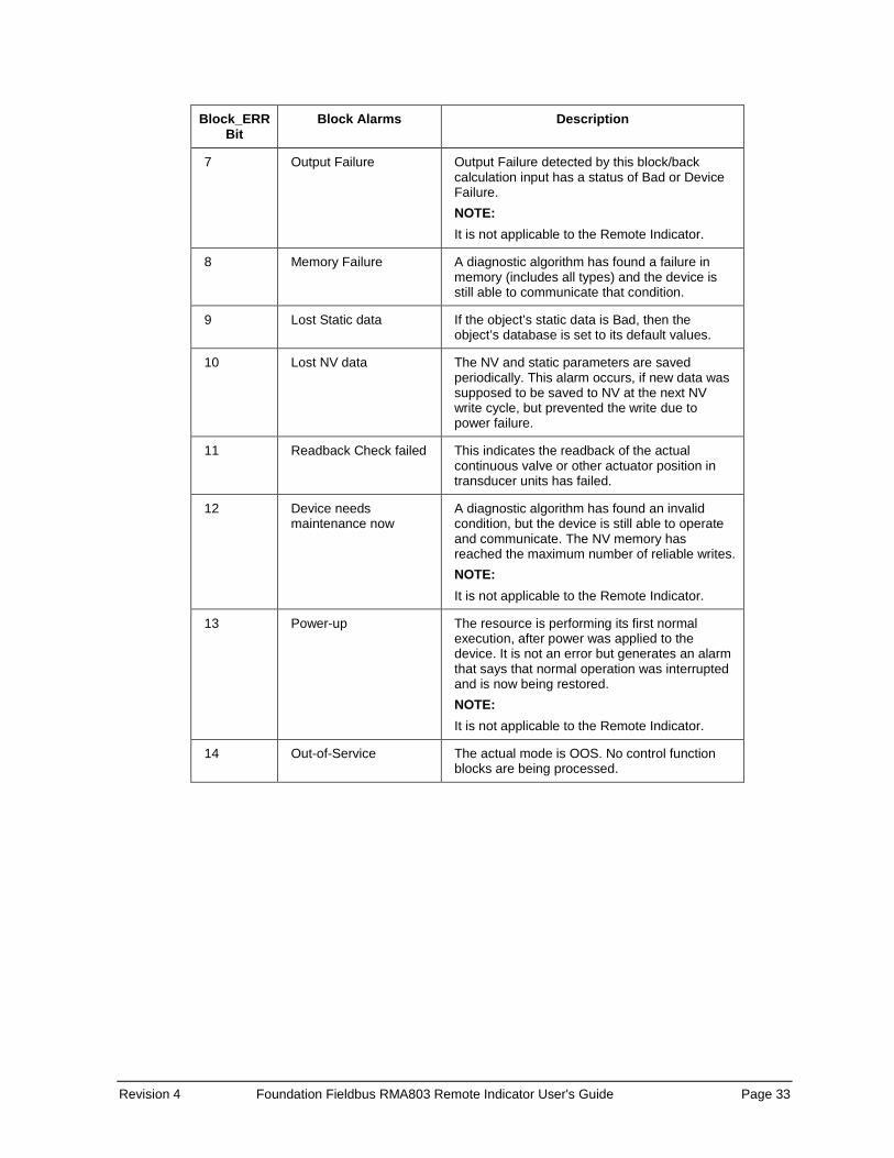
Revision 4 Foundation Fieldbus RMA803 Remote Indicator User's Guide Page 33
Block_ERR Bit
Block Alarms Description
7 Output Failure Output Failure detected by this block/back calculation input has a status of Bad or Device Failure. NOTE: It is not applicable to the Remote Indicator.
8 Memory Failure A diagnostic algorithm has found a failure in memory (includes all types) and the device is still able to communicate that condition.
9 Lost Static data If the object’s static data is Bad, then the object’s database is set to its default values.
10 Lost NV data The NV and static parameters are saved periodically. This alarm occurs, if new data was supposed to be saved to NV at the next NV write cycle, but prevented the write due to power failure.
11 Readback Check failed This indicates the readback of the actual continuous valve or other actuator position in transducer units has failed.
12 Device needs maintenance now
A diagnostic algorithm has found an invalid condition, but the device is still able to operate and communicate. The NV memory has reached the maximum number of reliable writes. NOTE: It is not applicable to the Remote Indicator.
13 Power-up The resource is performing its first normal execution, after power was applied to the device. It is not an error but generates an alarm that says that normal operation was interrupted and is now being restored. NOTE: It is not applicable to the Remote Indicator.
14 Out-of-Service The actual mode is OOS. No control function blocks are being processed.

Page 34 Foundation Fieldbus RMA803 Remote Indicator User's Guide Revision 4
Process Alarms A set of alarms that indicates a process value has exceeded a certain threshold. Process Alarm detection is based on the OUT value. The alarm limits can be configured for the following standard alarms: • High (HI_LIM) • High High (HI_HI_LIM) • Deviation High Limit (DEV_HI_LIM) • Deviation Low Limit (DEV_LO_LIM) • Low (LO_LIM) • Low Low (LO_LO_LIM) When the value OUT oscillates, ALARM_HYS is used to avoid alarm triggering. The priority of each alarm is set by the following parameters: • HI_PRI • HI_HI_PRI • DV_HI_PRI • DV_LO_PRI • LO_PRI • LO_LO_PRI
The following is the order of priority for alarms.
Table 13: Priority for Alarms
Priority Description
0 To disable the triggered alarm, the priority of an alarm condition is changed to 0.
1 Alarm condition with a priority 1 is reported to the system, but not reported as an event and alarm
2 Alarm condition with priority of 2 is reported to the system and event, but not reported as an alarm.
3-7 Alarm conditions of priority 3 to 7 are reported as advisory alarms.
8-15 Alarm conditions of priority 8 to 15 are reported as critical alarms.
ATTENTION Process alarms are not supported by all blocks.

Revision 4 Foundation Fieldbus RMA803 Remote Indicator User's Guide Page 35
5.3 Resource block The Resource block is used to describe characteristics of the Fieldbus device such as the device name, manufacturer, and serial number. The block does not contain any input or output parameters. The block contains data that is specific to the hardware associated with the resource. The resource block monitors and controls the general operation of the device hardware. For example, if the resource block is in out of service mode, it affects all the other blocks. The ITK_VER parameter is used to identify the version of the Interoperability Tester. The RMA803 Remote Indicator’s Revision and Versions, and Model Number can be obtained by executing the methods available in the resource block. The block modes are used to control major states of the resource: • The OOS mode stops all function block execution. • The Actual mode of the function blocks changes to OOS but the target mode does not change. • The AUTO mode allows normal operation of the resource.
Configuring the Resource block The Resource block supports scalar input only as HARD_TYPES. This parameter is a read-only bit string that indicates the types of hardware that are available for this resource. The RS_STATE parameter contains the operational state of the Function Block Application for the data containing that resource block.
RESTART The RESTART parameter allows degrees of initialization of the resource.
Restart Operation
Run (1) The passive state of the parameter.
Restart resource (2) Discards unnecessary alarms, and also discards the resource dynamic values.
Restart with defaults (3) Resets all configurable function block application objects to their initial value, which is their value before any configuration is done.
Restart processor (4) Provides a way to press the reset button on the processor associated with the resource.
Page 36 Foundation Fieldbus RMA803 Remote Indicator User's Guide Revision 4
Execution CYCLE TYPE
The parameter CYCLE_TYPE is a bit string that defines the types of cycles that are available for the resource and supports scheduled and block execution. CYCLE_SEL allows the person doing the configuration to indicate that one or more of these execution types can be used by the device. MIN_CYCLE_T is the minimum time to execute a cycle; the minimum cycle time supported is 100 ms.
MEMORY MEMORY_SIZE is the size of the resource for configuration of function blocks; it is represented in kilobytes. SHED_RCAS and SHED_ROUT set the time limit for loss of communication from a remote device. These constants are used by each function block and are configurable values.
MAX NOTIFY The MAX_NOTIFY parameter value is the maximum number of alert reports that this resource can send without getting a confirmation, and to control alert flooding, adjust the LIM_NOTIFY parameter to a lower value. If LIM_NOTIFY is set to zero, no alerts are reported. The CONFIRM_TIME parameter is the time for the resource to wait for confirmation of receipt of a report before trying again.
FEATURES The bit strings FEATURES and FEATURE_SEL determine optional behaviour of the resource. FEATURES bit string defines the available features; it is read-only. FEATURE_SEL is used to turn on an available feature by configuration.
Reports If the Reports option is set in the Features bit strings, the Remote Indicator actively sends alerts to host/master. If it is not set, the host/master must poll for alerts.

Revision 4 Foundation Fieldbus RMA803 Remote Indicator User's Guide Page 37
SOFT W LOCK and HARD W LOCK There are two types of write locks: Hardware write lock and Software write lock. The software write lock is used to lock the device. The software write lock does not need a jumper. A hardware write lock is provided with a jumper in the device to perform the write lock operation. If the WRITE_LOCK parameter is set, it prevents any external change to the static or non-volatile database in the Function Block Application of the resource. Block connections and calculation results proceeds normally but the configuration is locked. A hard write lock is provided by a jumper in the device as indicated in the FEATURES bit string. Clearing WRITE_LOCK generates the discrete alert WRITE_ALM at the WRITE_PRI priority. If the soft write lock bit is not set as True in the features bit strings, the writing to the parameter WRITE_LOCK is rejected by the device. For devices that support hard write lock and have the associated FEATURE_SEL attribute enabled, the parameter WRITE_LOCK is only an indicator of the state of write-lock. The writing to WRITE_LOCK is rejected by the device.
Software write lock To activate write lock, the soft write lock supported bit in FEATURE_SEL must be set, and then set the WRITE_LOCK to locked. To deactivate write lock, set the WRITE_LOCK to unlocked.
Hardware write lock To activate write lock, the hard write lock supported bit in FEATURE_SEL must be set, and additionally the write lock jumper must be in the correct position as determined by the manufacturer. When this is detected by the device, WRITE_LOCK is set to locked. If hard write lock is enabled in FEATURE_SEL, the configured value of soft write lock has no impact on device operation. To deactivate write lock, the jumper must be changed as FEATURE_SEL is not writeable during write lock. Once the device detects the change in jumper position, the write-lock is disabled and WRITE_LOCK is set to 1.
Install Date When the device is connected to the master/host, the time at which the device is powered up is taken as the install date. It is a read-only parameter.
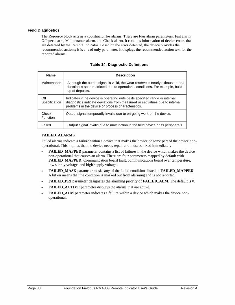
Page 38 Foundation Fieldbus RMA803 Remote Indicator User's Guide Revision 4
Field Diagnostics The Resource block acts as a coordinator for alarms. There are four alarm parameters: Fail alarm, Offspec alarm, Maintenance alarm, and Check alarm. It contains information of device errors that are detected by the Remote Indicator. Based on the error detected, the device provides the recommended actions; it is a read only parameter. It displays the recommended action text for the reported alarms.
Table 14: Diagnostic Definitions
Name Description
Maintenance Although the output signal is valid, the wear reserve is nearly exhausted or a function is soon restricted due to operational conditions. For example, build-up of deposits.
Off Specification
Indicates if the device is operating outside its specified range or internal diagnostics indicate deviations from measured or set values due to internal problems in the device or process characteristics.
Check Function
Output signal temporarily invalid due to on-going work on the device.
Failed Output signal invalid due to malfunction in the field device or its peripherals.
FAILED_ALARMS Failed alarms indicate a failure within a device that makes the device or some part of the device non-operational. This implies that the device needs repair and must be fixed immediately. • FAILED_MAPPED parameter contains a list of failures in the device which makes the device
non-operational that causes an alarm. There are four parameters mapped by default with FAILED_MAPPED: Communication board fault, communications board over temperature, low supply voltage, and high supply voltage.
• FAILED_MASK parameter masks any of the failed conditions listed in FAILED_MAPPED. A bit on means that the condition is masked out from alarming and is not reported.
• FAILED_PRI parameter designates the alarming priority of FAILED_ALM. The default is 0. • FAILED_ACTIVE parameter displays the alarms that are active. • FAILED_ALM parameter indicates a failure within a device which makes the device non-
operational.
Revision 4 Foundation Fieldbus RMA803 Remote Indicator User's Guide Page 39
MAINT_ALARMS A maintenance alarm indicates either the device or some part of the device needs maintenance. If the condition is ignored, the device eventually fails. • MAINT_MAPPED parameter contains a list of conditions indicating either the device or some
part of the device needs maintenance soon. If the condition is ignored, the device eventually fails. There are four parameters mapped by default with MAINT_MAPPED: Communications board fault, communications board over temperature, low supply voltage, and high supply voltage.
• MAINT_MASK parameter masks any of the failed conditions listed in MAINT_MAPPED. A bit on means that the condition is masked out from alarming and is not reported.
• MAINT_PRI designates the alarming priority of the MAINT_ALM. The default is 0. • MAINT_ACTIVE parameter displays the alarms that are active. • MAINT_ALM parameter indicates that the device needs maintenance. If the condition is
ignored, the device fails. CHECK_ALARMS It indicates that the output signal is temporarily invalid due to on-going work on the device. • CHECK_MAPPED parameter contains a list of informative conditions that do not have a
direct impact on the device's primary functions. • CHECK_MASK parameter masks any of the failed conditions listed in CHECK_MAPPED.
A bit on means the condition is masked out from alarming and is not reported. • CHECK_PRI parameter designates the alarming priority of the CHECK_ALM. The default is
0. • CHECK_ACTIVE parameter displays the check alarms that are active. • CHECK_ALM parameter indicates check alarms. These conditions do not have a direct impact
on the process or device integrity.
Page 40 Foundation Fieldbus RMA803 Remote Indicator User's Guide Revision 4
OFFSPEC_ALARMS Indicates if the device is operating outside its specified range or internal diagnostics indicates deviations from measured or set values due to internal problems in the device or process characteristics. • OFFSPEC_MAPPED parameter contains a list of informative conditions that do not have a
direct impact on the device's primary functions. • OFFSPEC_MASK parameter masks any of the failed conditions listed in
OFFSPEC_MAPPED. A bit on means the condition is masked out from alarming and is not reported.
• OFFSPEC_PRI parameter designates the alarming priority of the OFFSPEC_ALM. The default is 0.
• OFFSPEC_ACTIVE parameter displays the offspec alarms that are active. • OFFSPEC_ALM parameter indicates offspec alarms. These conditions do not have a direct
impact on the process or device integrity. RECOMMENDED_ACTION
The RECOMMENDED_ACTION parameter displays a text string that give a recommended course of action to take based on which type and which specific event of the alarms is active.
FD_SIMULATE When simulation is enabled the Field Diagnostics conditions are taken from the Diagnostic Simulate Value, or else the conditions are taken from Diagnostic Value, and the RECOMMENDED_ACTION parameter displays the text as ‘Simulation Active’.
ATTENTION Note that FD_SIMULATE can be enabled only if the simulation jumper is enabled in the device. For more information refer section 8.6
Revision 4 Foundation Fieldbus RMA803 Remote Indicator User's Guide Page 41
MAINTENANCE_MODE It indicates if the device is available for maintenance. When the resource block is in AUTO mode, MAINTENANCE_MODE parameter displays the text as 'Chk with Oper' i.e., the device is in process and is not available for maintenance. When the resource block is in OOS mode, MAINTENANCE_MODE parameter displays the text as ‘Avail for Maint' i.e., the device is out of process and is available for maintenance. The same text is displayed in the advanced display. 'Chk with Oper'- Check with operator to determine availability. ‘Avail for Maint'- The device is available for maintenance.
Parameter List Table 15: Resource block parameters
Parameter Description
ST_REV The revision level of the static data associated with the function block.
TAG_DESC The user description of the application of the block.
STRATEGY Used to identify grouping of blocks.
ALERT_KEY The identification number of the plant unit.
MODE_BLK The actual, target, permitted, and normal modes of the block.
BLOCK_ERR Reflects the error status associated with the hardware or software components associated with a block. It is a bit string, so that multiple errors may be shown.
RS_STATE Indicates the State of the function block application state machine.
TEST_RW Read/write test parameter is used only for conformance testing.
DD_RESOURCE String identifying the tag of the resource, which contains the Device Description for the resource.
MANUFAC_ID Manufacturer identification number is used by an interface device to locate the DD file for the resource.
DEV_TYPE Manufacturer model number associated with the resource. It is used by interface devices to locate the DD file for the resource.
DEV_REV Manufacturer revision number associated with the resource. It is used by an interface device to locate the DD file for the resource.
DD_REV Revision of the DD associated with the resource. It is used by the interface device to locate the DD file for the resource.
GRANT_DENY Options for controlling access of host computer and local control panels to operating, tuning and alarm parameters of the block.
HARD_TYPES The types of hardware available as channel numbers. The supported hardware type is SCALAR_INPUT and SCALAR_OUTPUT.
RESTART Allows a manual restart to be initiated.
FEATURES Used to show supported resource block options. The supported features are: REPORT, SOFT_WRITE_LOCK, HARD_WRITE_LOCK, and MULTI_BIT_ALARM.
FEATURE_SEL Used to select resource block FEATURE_SEL options
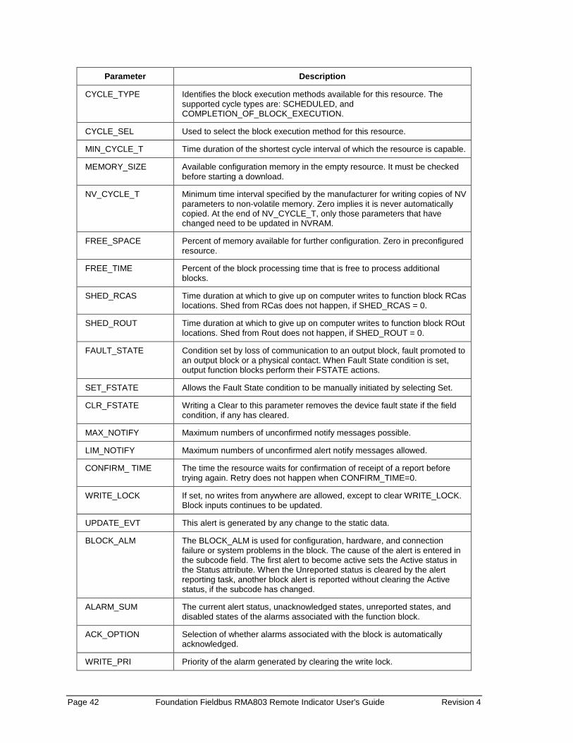
Page 42 Foundation Fieldbus RMA803 Remote Indicator User's Guide Revision 4
Parameter Description
CYCLE_TYPE Identifies the block execution methods available for this resource. The supported cycle types are: SCHEDULED, and COMPLETION_OF_BLOCK_EXECUTION.
CYCLE_SEL Used to select the block execution method for this resource.
MIN_CYCLE_T Time duration of the shortest cycle interval of which the resource is capable.
MEMORY_SIZE Available configuration memory in the empty resource. It must be checked before starting a download.
NV_CYCLE_T Minimum time interval specified by the manufacturer for writing copies of NV parameters to non-volatile memory. Zero implies it is never automatically copied. At the end of NV_CYCLE_T, only those parameters that have changed need to be updated in NVRAM.
FREE_SPACE Percent of memory available for further configuration. Zero in preconfigured resource.
FREE_TIME Percent of the block processing time that is free to process additional blocks.
SHED_RCAS Time duration at which to give up on computer writes to function block RCas locations. Shed from RCas does not happen, if SHED_RCAS = 0.
SHED_ROUT Time duration at which to give up on computer writes to function block ROut locations. Shed from Rout does not happen, if SHED_ROUT = 0.
FAULT_STATE Condition set by loss of communication to an output block, fault promoted to an output block or a physical contact. When Fault State condition is set, output function blocks perform their FSTATE actions.
SET_FSTATE Allows the Fault State condition to be manually initiated by selecting Set.
CLR_FSTATE Writing a Clear to this parameter removes the device fault state if the field condition, if any has cleared.
MAX_NOTIFY Maximum numbers of unconfirmed notify messages possible.
LIM_NOTIFY Maximum numbers of unconfirmed alert notify messages allowed.
CONFIRM_ TIME The time the resource waits for confirmation of receipt of a report before trying again. Retry does not happen when CONFIRM_TIME=0.
WRITE_LOCK If set, no writes from anywhere are allowed, except to clear WRITE_LOCK. Block inputs continues to be updated.
UPDATE_EVT This alert is generated by any change to the static data.
BLOCK_ALM The BLOCK_ALM is used for configuration, hardware, and connection failure or system problems in the block. The cause of the alert is entered in the subcode field. The first alert to become active sets the Active status in the Status attribute. When the Unreported status is cleared by the alert reporting task, another block alert is reported without clearing the Active status, if the subcode has changed.
ALARM_SUM The current alert status, unacknowledged states, unreported states, and disabled states of the alarms associated with the function block.
ACK_OPTION Selection of whether alarms associated with the block is automatically acknowledged.
WRITE_PRI Priority of the alarm generated by clearing the write lock.

Revision 4 Foundation Fieldbus RMA803 Remote Indicator User's Guide Page 43
Parameter Description
WRITE_ALM This alert is generated if the write lock parameter is cleared.
ITK_VER Major revision number of the interoperability test case used in certifying this device as interoperable. The format and range are controlled by the Fieldbus Foundation. The current ITK version is 6.0.1.
FD_VER A parameter equal to the value of the major version of the Field Diagnostics specification that the device is designed for.
FD_RECOMMEN_ACT
Enumerated list of recommended actions displayed with a device alert.
FD_FAIL_PRI Designates the alarming priority of the FAIL_ALM. The valid range is 0-15.
FD_FAIL_MAP Mapped FAIL_ALM alarm conditions, and corresponds bit for bit to the FAIL_ACTIVE. A bit on means that the corresponding alarm condition is Mapped and it is detected. A bit off means the corresponding alarm condition is disabled and is not detected.
FD_FAIL_MASK Mask of FAIL_ALM. It corresponds to the bit of bit to FAIL_ACTIVE. A bit on means that the condition is masked out from alarming.
FD_FAIL_ACTIVE Enumerated list of failure conditions within a device.
FD_FAIL_ALM Alarm indicating a failure within a device which makes the device non-operational.
FD_MAINT_PRI Designates the alarming priority of the MAINT_ALM. The valid range is 0-15.
FD_MAINT_MAP Mapped MAINT_ALM alarm conditions and corresponds bit for bit to the MAINT_ACTIVE. A bit on means that the corresponding alarm condition is Mapped and is not detected. A bit off means the corresponding alarm condition is disabled and is not detected.
FD_MAINT_MASK Mask of MAINT_ALM. It corresponds to the bit of bit to MAINT_ACTIVE. A bit on means that the condition is masked out from alarming.
FD_MAINT_ACTIVE Enumerated list of maintenance conditions within a device.
FD_MAINT_ALM Alarm indicating the device needs maintenance soon. If the condition is ignored, the device eventually fails.
FD_OFFSPEC_PRI Designates the alarming priority of the OFFSPEC_ALM. The valid range is 0-15.
FD_OFFSPEC_MAP Mapped OFFSPEC_ALM alarm conditions. Corresponds bit for bit to the OFFSPEC_ACTIVE. A bit on implies that the corresponding alarm condition is Mapped and detected. A bit off means the corresponding alarm condition is disabled and is not detected.
FD_OFFSPEC_MASK
Mask of OFFSPEC_ALM. It corresponds to the bit of bit to OFFSPEC_ACTIVE. A bit on implies that the condition is masked out from alarming.
FD_OFFSPEC_ACTIVE
Enumerated list of offspec conditions within a device.
FD_OFFSPEC_ALM Alarm indicating offspec alarms. These conditions do not have a direct impact on the process or device integrity.
FD_CHECK_PRI Designates the alarming priority of the CHECK_ALM. The valid range is 0-15.
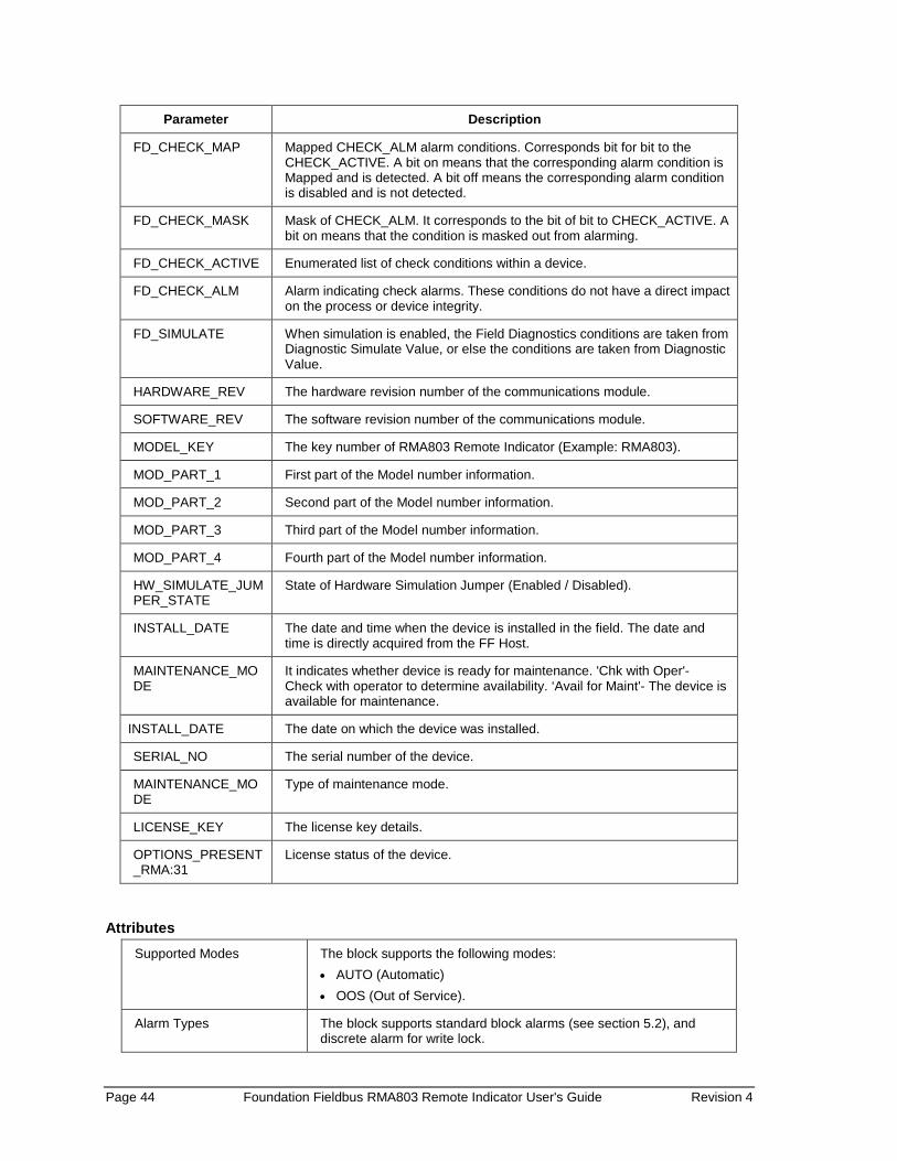
Page 44 Foundation Fieldbus RMA803 Remote Indicator User's Guide Revision 4
Parameter Description
FD_CHECK_MAP Mapped CHECK_ALM alarm conditions. Corresponds bit for bit to the CHECK_ACTIVE. A bit on means that the corresponding alarm condition is Mapped and is detected. A bit off means the corresponding alarm condition is disabled and is not detected.
FD_CHECK_MASK Mask of CHECK_ALM. It corresponds to the bit of bit to CHECK_ACTIVE. A bit on means that the condition is masked out from alarming.
FD_CHECK_ACTIVE Enumerated list of check conditions within a device.
FD_CHECK_ALM Alarm indicating check alarms. These conditions do not have a direct impact on the process or device integrity.
FD_SIMULATE When simulation is enabled, the Field Diagnostics conditions are taken from Diagnostic Simulate Value, or else the conditions are taken from Diagnostic Value.
HARDWARE_REV The hardware revision number of the communications module.
SOFTWARE_REV The software revision number of the communications module.
MODEL_KEY The key number of RMA803 Remote Indicator (Example: RMA803).
MOD_PART_1 First part of the Model number information.
MOD_PART_2 Second part of the Model number information.
MOD_PART_3 Third part of the Model number information.
MOD_PART_4 Fourth part of the Model number information.
HW_SIMULATE_JUMPER_STATE
State of Hardware Simulation Jumper (Enabled / Disabled).
INSTALL_DATE The date and time when the device is installed in the field. The date and time is directly acquired from the FF Host.
MAINTENANCE_MODE
It indicates whether device is ready for maintenance. 'Chk with Oper'- Check with operator to determine availability. ‘Avail for Maint'- The device is available for maintenance.
INSTALL_DATE The date on which the device was installed.
SERIAL_NO The serial number of the device.
MAINTENANCE_MODE
Type of maintenance mode.
LICENSE_KEY The license key details.
OPTIONS_PRESENT_RMA:31
License status of the device.
Attributes Supported Modes The block supports the following modes:
• AUTO (Automatic) • OOS (Out of Service).
Alarm Types The block supports standard block alarms (see section 5.2), and discrete alarm for write lock.
Revision 4 Foundation Fieldbus RMA803 Remote Indicator User's Guide Page 45
5.4 Diagnostic Transducer block The Diagnostics Transducer block supports the Remote Indicator electronic diagnostics.
ATTENTION The electronics temperature can be tracked in 8 ways: • Current Temperature • Units • Maximum Temperature • Minimum Temperature • Maximum Temperature Accumulated Minutes • Minimum Temperature Accumulated Minutes • Maximum Temperature Date • Minimum Temperature Date
Execution
The block has Device diagnostics. The block is executed as follows: Device Diagnostics Electronics Housing Temperature Diagnostics Electronics housing temperature is the temperature of the electronic housing unit and Electronics temperature value is its corresponding value. Time in Service The amount of time the device is in operation and is shown in minutes. Service Life The average service life of the device under ideal conditions is 27.3 years. But, the service life varies depending on external factors such as temperature. Service life indicates the amount of service life that has been consumed by the device. Service Life is dependent on the temperature of the device only. The Service life is calculated in percentage.

Page 46 Foundation Fieldbus RMA803 Remote Indicator User's Guide Revision 4
Stress monitor It is the amount of time the device has been used under stressful conditions. For example, say temperature of the device. The stress monitor is based on the temperature of the device. The Stress monitor is calculated in percentage. Stress monitor = Amount of time the device was under stressful conditions
------------------------------------------------------------------------- Time in Service of the device
Parameter List
Table 16: Diagnostic Transducer block parameters
Parameter Description
ST_REV The revision level of the static data associated with the function block.
TAG_DESC The user description of the application of the block.
STRATEGY Used to identify grouping of blocks.
ALERT_KEY The identification number of the plant unit.
MODE The actual, target, permitted, and normal modes of the block.
BLOCK_ERR
Reflects the error status associated with the hardware or software components associated with a block. It is a bit string, so that multiple errors may be shown.
UPDATE_EVT This alert is generated by any change to the static data.
BLOCK_ALM The BLOCK_ALM is used for all configuration, hardware, and connection failure or system problems in the block. The cause of the alert is entered in the subcode field. The first alert to become active sets the Active status in the Status attribute. As soon as the Unreported status is cleared by the alert reporting task, another block alert may be reported without clearing the Active status, if the subcode has changed.
EL_TEMP_DIAGNOSTIC Electronic Temperature Diagnostic parameters.
POWER_TRAC Power Up Track Data.
OP_VOLTAGE Operating Voltage.
TIME_IN_SERVICE Summation of time in minutes that power has been applied to the device since leaving the factory.
SERVICE_LIFE It is the elapsed Service life of device in percentage.
STRESS_MONITOR It monitors various diagnostic parameters which are then input into an algorithm to calculate an estimated percent of time that the Remote Indicator has spent in stressful conditions.
HON_RES_1 Reserved for Honeywell use only.
HON_RES_2 Reserved for Honeywell use only.

Revision 4 Foundation Fieldbus RMA803 Remote Indicator User's Guide Page 47
Attributes
Supported Modes The block supports the following modes:
• AUTO (Automatic) • OOS (Out of Service).
Alarm Types The block supports standard block alarms (see section 5.2).

Page 48 Foundation Fieldbus RMA803 Remote Indicator User's Guide Revision 4
5.5 LCD Transducer block The LCD Transducer block supports Advanced Display. The block is used to configure the advanced display connected to the RMA803 Remote Indicator. The block stores the LCD configurations, and sends these values to the Display while the Remote Indicator is powered up or restarted.
Figure 9: LCD Transducer block
ATTENTION The initial configuration of LCD transducer is configured to show eight screens.
The Display shows the available set of process variables, and all function block inputs/outputs. In addition, the block reports the current device status and errors. If a function block parameter which is not currently a part of the control strategy is selected, an error does not appear, the PV value shown is 0 and the status of the PV shows Bad and block mode is shown as OOS.
Execution Advanced Display
The Advanced Display provides three formats, and describes the field in each of the three Advanced Display formats namely, PV, Bar Graph, and PV Trend. Essentially, all three formats provide the same information, but with the following differences: • PV
It is a user configurable display, and it shows the configured PV. • Bar Graph
It is a user configurable 126 segment Bar Graph with range settings. The Bar Graph displays the current value of the configured PV.
• PV Trend It is a user-configurable display period from one hour to 24 hours. The chart displays minimum, maximum, and average of the configured PV over the selected trend period.
The LCD Transducer block supports configuration of up to eight LCD screens on the advanced displays. By default, the Display has a screen configured with default settings. Remote Indicator Messaging The RMA803 Remote Indicator messaging is a feature that allows message typed through host (up to 64 alphanumeric characters) which is sent to the Local Display of the RMA803 Remote Indicator. The message is shown on the Display interspersed with the configured screens. Clear Message To stop displaying the message, select the Clear Message method. After selecting this option, the device clears the entered Message and it is not shown in the Display. Table 17 lists the allowed parameters that can be configured using the LCD block.
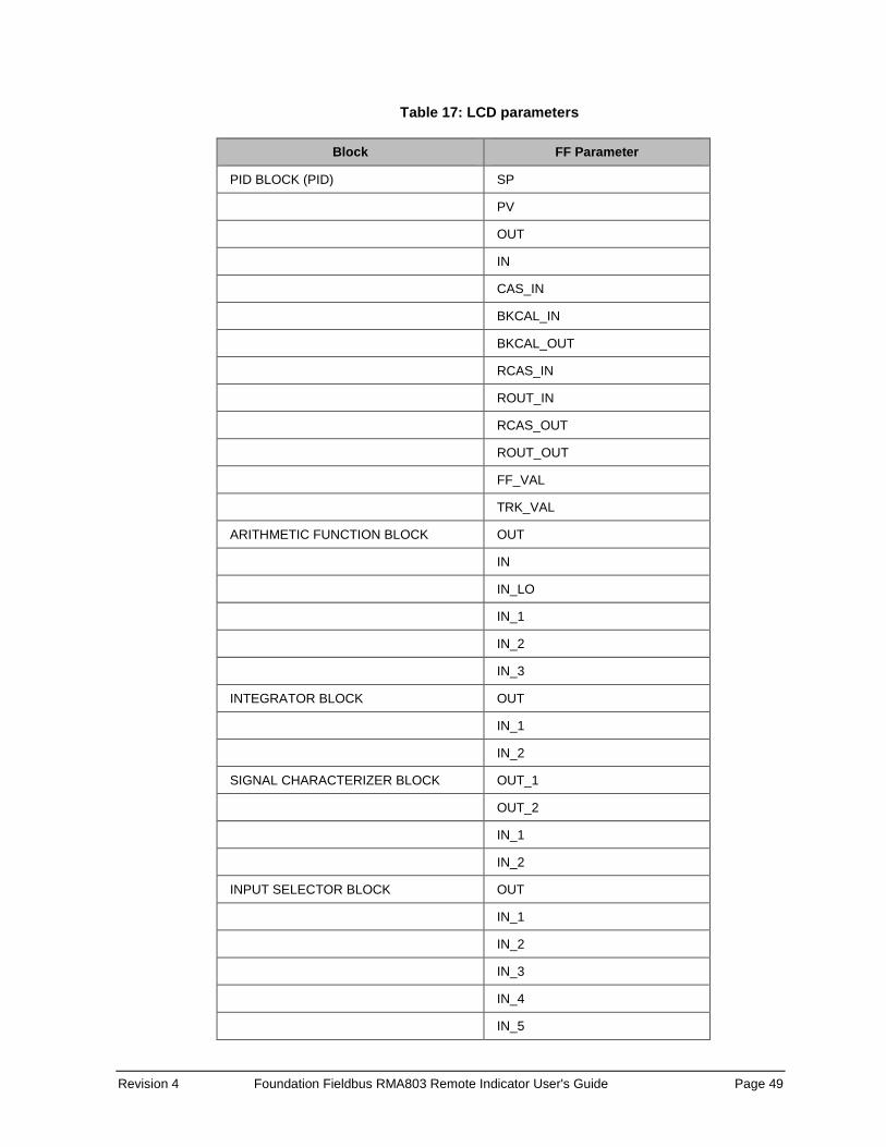
Revision 4 Foundation Fieldbus RMA803 Remote Indicator User's Guide Page 49
Table 17: LCD parameters
Block FF Parameter
PID BLOCK (PID) SP
PV
OUT
IN
CAS_IN
BKCAL_IN
BKCAL_OUT
RCAS_IN
ROUT_IN
RCAS_OUT
ROUT_OUT
FF_VAL
TRK_VAL
ARITHMETIC FUNCTION BLOCK OUT
IN
IN_LO
IN_1
IN_2
IN_3
INTEGRATOR BLOCK OUT
IN_1
IN_2
SIGNAL CHARACTERIZER BLOCK OUT_1
OUT_2
IN_1
IN_2
INPUT SELECTOR BLOCK OUT
IN_1
IN_2
IN_3
IN_4
IN_5
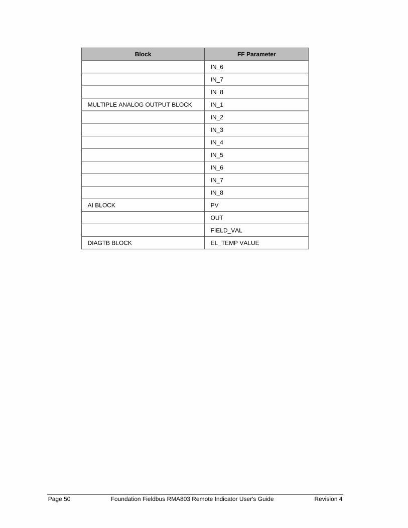
Page 50 Foundation Fieldbus RMA803 Remote Indicator User's Guide Revision 4
Block FF Parameter
IN_6
IN_7
IN_8
MULTIPLE ANALOG OUTPUT BLOCK IN_1
IN_2
IN_3
IN_4
IN_5
IN_6
IN_7
IN_8
AI BLOCK PV
OUT
FIELD_VAL
DIAGTB BLOCK EL_TEMP VALUE
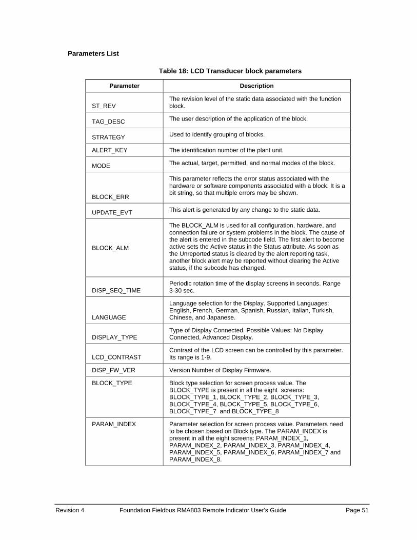
Revision 4 Foundation Fieldbus RMA803 Remote Indicator User's Guide Page 51
Parameters List
Table 18: LCD Transducer block parameters
Parameter Description
ST_REV The revision level of the static data associated with the function block.
TAG_DESC The user description of the application of the block.
STRATEGY Used to identify grouping of blocks.
ALERT_KEY The identification number of the plant unit.
MODE The actual, target, permitted, and normal modes of the block.
BLOCK_ERR
This parameter reflects the error status associated with the hardware or software components associated with a block. It is a bit string, so that multiple errors may be shown.
UPDATE_EVT This alert is generated by any change to the static data.
BLOCK_ALM
The BLOCK_ALM is used for all configuration, hardware, and connection failure or system problems in the block. The cause of the alert is entered in the subcode field. The first alert to become active sets the Active status in the Status attribute. As soon as the Unreported status is cleared by the alert reporting task, another block alert may be reported without clearing the Active status, if the subcode has changed.
DISP_SEQ_TIME Periodic rotation time of the display screens in seconds. Range 3-30 sec.
LANGUAGE
Language selection for the Display. Supported Languages: English, French, German, Spanish, Russian, Italian, Turkish, Chinese, and Japanese.
DISPLAY_TYPE Type of Display Connected. Possible Values: No Display Connected, Advanced Display.
LCD_CONTRAST Contrast of the LCD screen can be controlled by this parameter. Its range is 1-9.
DISP_FW_VER Version Number of Display Firmware.
BLOCK_TYPE Block type selection for screen process value. The BLOCK_TYPE is present in all the eight screens: BLOCK_TYPE_1, BLOCK_TYPE_2, BLOCK_TYPE_3, BLOCK_TYPE_4, BLOCK_TYPE_5, BLOCK_TYPE_6, BLOCK_TYPE_7 and BLOCK_TYPE_8
PARAM_INDEX Parameter selection for screen process value. Parameters need to be chosen based on Block type. The PARAM_INDEX is present in all the eight screens: PARAM_INDEX_1, PARAM_INDEX_2, PARAM_INDEX_3, PARAM_INDEX_4, PARAM_INDEX_5, PARAM_INDEX_6, PARAM_INDEX_7 and PARAM_INDEX_8.

Page 52 Foundation Fieldbus RMA803 Remote Indicator User's Guide Revision 4
Parameter Description
UNIT_TYPES Unit selection for screen process value. Appropriate units need to be selected based on the configured parameter. If desired units are not present, 'custom' may be selected. The UNIT_TYPES is present in all the eight screens: UNIT_TYPES_1, UNIT_TYPES_2, UNIT_TYPES_3, UNIT_TYPES_4, UNIT_TYPES_5, UNIT_TYPES_6, UNIT_TYPES_7 and UNIT_TYPES_8
CUSTOM_UNIT Character string to represent custom units. This value is used when Unit type of 'custom' is selected. Size: 8 Characters. The CUSTOM_UNIT is present in all the eight screens: CUSTOM_UNIT_1, CUSTOM_UNIT_2, CUSTOM_UNIT_3, and CUSTOM_UNIT_4.
CUSTOM_TAG Tag to be displayed for the screen. Length: 14 Characters. The CUSTOM_TAG is present in all the eight screens: CUSTOM_TAG_1, CUSTOM_TAG_2, CUSTOM_TAG_3, CUSTOM_TAG_4, CUSTOM_TAG_5, CUSTOM_TAG_6, CUSTOM_TAG_7 and CUSTOM_TAG_8.
DISPLAY_TEMPLATE Represents the display screen template. Possible Values: a) PV: Regular PV value is displayed b) PV and Trend: PV value followed by a Trend is shown on
the display c) PV and Bargraph: PV value followed by a Bargraph is
shown on the display d) None: Screen will not be seen. The DISPLAY_TEMPLATE is present in all the eight screens: DISPLAY_TEMPLATE_1, DISPLAY_TEMPLATE_2, DISPLAY_TEMPLATE_3, DISPLAY_TEMPLATE_4, DISPLAY_TEMPLATE_5, DISPLAY_TEMPLATE_6, DISPLAY_TEMPLATE_7 and DISPLAY_TEMPLATE_8
DECIMALS Number of digits to display after the decimal point. Range: 0 - 3. DECIMALS is present in all the eight screens: DECIMALS_1, DECIMALS_2, DECIMALS_3, DECIMALS_4, DECIMALS_5, DECIMALS_6, DECIMALS_7 and DECIMALS_8
TREND_DURATION Duration of a trend screen in hours. Its valid range is 1-24. The TREND_DURATION is present in all the eight screens: TREND_DURATION_1, TREND_DURATION_2, TREND_DURATION_3, TREND_DURATION_4, TREND_DURATION_5, TREND_DURATION_6, TREND_DURATION_7 and TREND_DURATION_8.
PV_LOLIM PV low limit
PV_HILIM PV high limit
DISPLAY_MESSAGE A message with a maximum of 64 characters that appears on the advanced display of the Remote Indicator.
SCREEN_ROTATION Configurable screen rotation timing (4 to 30 sec).
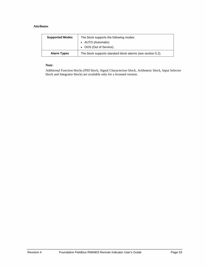
Revision 4 Foundation Fieldbus RMA803 Remote Indicator User's Guide Page 53
Attributes
Supported Modes The block supports the following modes:
• AUTO (Automatic) • OOS (Out of Service).
Alarm Types The block supports standard block alarms (see section 5.2).
Note: Additional Function blocks (PID block, Signal Characterizer block, Arithmetic block, Input Selector block and Integrator block) are available only for a licensed version.

Page 54 Foundation Fieldbus RMA803 Remote Indicator User's Guide Revision 4
5.6 Proportional Integral Derivative (PID) block with auto tune The PID block is the key to many control schemes, and it is commonly used. The PID function integrates the errors. If there is difference in process time constants of a primary process and secondary process measurement, then the block can be cascaded if required. Auto tuning is a feature that tunes the PID constants as per the process automatically.
Figure 10: PID block
Figure 11: PID block schematic diagram

Revision 4 Foundation Fieldbus RMA803 Remote Indicator User's Guide Page 55
Execution The Process Value to be controlled is connected to the IN input. The value is passed through a filter, and its time constant is PV_FTIME. The value is then shown as the PV, which is used in conjunction with the SP in the PID algorithm. A PID does not integrate if the limit status of IN input is constant, or if further control action based on the PID error proceeds IN input further towards its active status limit. A full PV and DV alarm sub-function is provided. The PV has a status, although it is a contained parameter. This status is a copy of IN’s status, unless IN is Good and there is a PV or block alarm. The full cascade SP sub-function is used with rate and absolute limits. The block has additional control options which cause the SP value to track the PV value. The SP value tracks the PV value while the block is in Actual mode of IMan, LO, or ROut, or when the target mode of the block is MAN. The block provides a switch for BYPASS, which is available to the operator if the Bypass Enable control option is set as True. BYPASS can be used in secondary cascade controllers that have a Bad PV. The BYPASS Enable option is required, so if BYPASS is set as True, not all cascade control schemes are stable. BYPASS can only be changed when the block mode is in MAN or OOS mode. When BYPASS is set, the value of SP, in percent of range, is passed directly to the target output, and the value of OUT is used for BKCAL_OUT. When the mode is changed to Cas, the upstream block is requested to initialize to the value of OUT. When a block is in Cas mode, on the transition out of BYPASS, the upstream block is requested to initialize to the PV value, irrespective of the “Use PV for BKCAL_OUT” option. GAIN, RESET, and RATE are the tuning constants for the P, I, and D terms, respectively. The block provides existing controllers that are tuned by the inverse value of some or all of them, such as proportional band and repeats per minute. The human interface to these parameters must be able to display the user's preference. BAL_TIME parameter can be used to set the rate at which the I term moves towards balancing the difference between the previous integral term and the limited output. The Direct Acting control option, if set as True, causes the output to increase when the PV exceeds the SP. If set as False, the output decreases when the PV exceeds the SP. The Direct Acting control option must be set carefully, as it can cause a difference between positive and negative feedback.
ATTENTION The Direct Acting control option can never be changed while in AUTO mode. The setting of the option must also be used in calculating the limit state for BKCAL_OUT.

Page 56 Foundation Fieldbus RMA803 Remote Indicator User's Guide Revision 4
The output supports the feed forward algorithm. The FF_VAL input brings in an external value which is proportional to some disturbance in the control loop. The value is converted to percent of output span using the values of parameter FF_SCALE. This value is multiplied by the FF_GAIN and added to the target output of the PID algorithm. If the status of FF_VAL is Bad, the last usable value is used as this prevents bumping the output. When the status returns to Good, the block adjusts its integral term to maintain the previous output. The output supports the track algorithm. The block provides an option to use either the SP value after limiting or the PV value for the BKCAL_OUT value. PID Control block is an algorithm that produces an output signal in response to the measured variable and the setpoint. The PID block allows you to choose either a standard PID control equation (Ideal) or a robust PID equation defined by Honeywell. This selection is defined in the PID_FORM parameter. The output has three terms, namely Proportional, Integral, and Derivative. The output is adjusted by tuning constants. There are three tuning constants in the ideal PID equation. The robust PID uses four tuning constants: 1. GAIN is the tuning constant of the Proportional term. 2. RESET is the tuning constant of the Integral. 3. RATE is the tuning constant of the Derivative. RATE is usually modified by a lag, which is set
at some fixed ratio higher than the rate time, to create a rate gain. There is no lag with the rate in this implementation.
4. OUT_LAG is the fourth tuning constant used in the robust PID; it adds roll off to the output response. The action is similar to PID with rate gain.
PID Ideal and PID Robust The ideal equation is a parallel or non-interacting implementation of PID control using three tuning constants. It automatically fixes OUT_LAG to 16 times the RATE time constant. This produces response characteristics equivalent to the algorithms used in TPS products. The robust equation is the same parallel implementation of ideal PID control but allows the engineer to set the OUT_LAG and effectively change the rate gain. ALGO_TYPE is a configuration parameter that contains one of three selected algorithm types, A, B, or C. Where: • A - RATE, GAIN and RESET all act on the error between set point and measured variable. • B - RATE acts on the measured variable only, GAIN and RESET use the error. • C - RATE and GAIN act on the measured variable only, and RESET uses the error.
PID Tuning Parameters Table lists the valid ranges for the tuning parameters for the PID block. Note that OUT_LAG parameter is not configurable when Ideal PID is selected (PID_FORM = 1) and can be configured when Robust PID is selected (PID_FORM = 2).
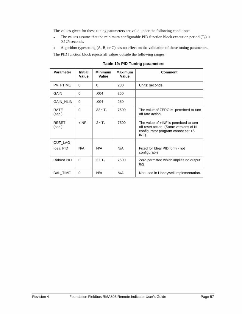
Revision 4 Foundation Fieldbus RMA803 Remote Indicator User's Guide Page 57
The values given for these tuning parameters are valid under the following conditions: • The values assume that the minimum configurable PID function block execution period (Ts) is
0.125 seconds. • Algorithm typesetting (A, B, or C) has no effect on the validation of these tuning parameters.
The PID function block rejects all values outside the following ranges:
Table 19: PID Tuning parameters
Parameter Initial Value
Minimum Value
Maximum Value
Comment
PV_FTIME 0 0 200 Units: seconds.
GAIN 0 .004 250
GAIN_NLIN 0 .004 250
RATE (sec.)
0 32 • Ts 7500 The value of ZERO is permitted to turn off rate action.
RESET (sec.)
+INF 2 • Ts 7500 The value of +INF is permitted to turn off reset action. (Some versions of NI configurator program cannot set +/- INF).
OUT_LAG Ideal PID
N/A
N/A
N/A
Fixed for Ideal PID form - not configurable.
Robust PID 0 2 • Ts 7500 Zero permitted which implies no output lag.
BAL_TIME 0 N/A N/A Not used in Honeywell Implementation.
Page 58 Foundation Fieldbus RMA803 Remote Indicator User's Guide Revision 4
Auto tuning Cycle tuning The PID block supports the Cycle tuning algorithm. In Cycle tuning, the tuning parameter values are derived from the process response to the resultant action of causing the PV to oscillate about a SP value. The tuning method uses the measured ultimate gain and period to produce tuning parameter values, by using the relationship developed by Ziegles Nichols equations. Cycle tuning does not distinguish between process lags and always results in gain based on PV amplitude, and calculates the values of Reset and Rate based on time of the SP crossings using a fixed ratio of 4 to 1. Initially, this method does not require a stable process. Cycle tuning is applicable to Three Position Step control, and is used for integrating process.
Auto tuning procedure There are nine parameters applicable for auto tuning: AT_TYPE, TUNING_CRITERIA, TUNE_REQ, ATI, AT_MODE, AT_ERR, AT_GAIN, AT_RESET, and AT_RATE. AT_Type There are two types of selections, namely Disable and Cycle Tune. When Disable is selected, AT_MODE becomes inactive. When Cycle Tune is selected, AT_MODE becomes AT Ready. TUNING_CRITERIA There are two types of tuning criteria available for selection: Normal and Fast. • NORMAL - Conservative tuning designed to reduce overshoot as compared to FAST. • FAST - Aggressive tuning designed to provide quarter-dampened response. TUNE_REQ TUNE_REQ can be turned ON only in the following modes, namely AUTO, CAS, RCAS, and ROUT. The ATI value becomes 1, and AT_ERROR shows the status as Run, this shows that auto tuning is in progress. If AT_ERROR shows OK, auto tuning is successful. AT_GAIN, AT_REST, AT_RATE gets updated automatically and same values are copied to GAIN, RESET and RATE respectively.

Revision 4 Foundation Fieldbus RMA803 Remote Indicator User's Guide Page 59
Parameter list
Table 20: PID block parameters
Parameter Description
ST_REV The revision level of the static data associated with the function block. The revision value is incremented each time a static parameter value in the block is changed.
TAG_DESC The user description of the application of the block.
STRATEGY Used to identify grouping of blocks. This data is not checked or processed by the block.
ALERT_KEY The identification number of the plant unit. This information may be used in the host for sorting alarms, etc.
MODE_BLK The actual, target, permitted, and normal modes of the block. Target: The mode to “go to” Actual: The mode the “block is currently in” Permitted: Allowed modes that target may take on Normal: Most common mode for target
BLOCK_ERR This parameter reflects the error status associated with the hardware or software components associated with a block. It is a bit string so that multiple errors may be shown.
PV The process variable used in block execution.
SP It is the target block setpoint value. It is the result of setpoint limiting and setpoint rate of change limiting.
OUT The block input value and status.
PV_SCALE The high and low scale values, engineering units code, and number of digits to the right of the decimal point associated with PV.
OUT_SCALE The high and low scale values, engineering units code, and number of digits to the right of the decimal point associated with OUT.
GRANT_DENY Options for controlling access of host computers and local control panels to operating, tuning, and alarm parameters of the block. Not used by the device.
CONTROL_OPTS Specify control strategy options. The supported control options for the PID block are Track enable, Track in Manual, SP-PV Track in MAN, SP-PV Track in LO or IMAN, Use PV for BKCAL_OUT, Direct Acting, SP Track retain, SP-PV Track Out, Restrict SP to limits in CAS and RCAS, No output limits in MAN.
STATUS_OPTS It helps to select options for status handling and processing. The supported status option for the PID block is Target to Manual if Bad IN. IFS if Bad IN, IFS if Bad CAS_IN, Use Uncertain as Good, Target to next permitted mode if Bad CAS_IN, Target to MAN if Bad TRK_IN_D and IFS if Bad TRK_IN_D.
IN The connection for the PV input from another block.
PV_FTIME The time constant of the first-order PV filter. It is the time required for a 63 percent change in the IN value.

Page 60 Foundation Fieldbus RMA803 Remote Indicator User's Guide Revision 4
Parameter Description
BYPASS Used to override the calculation of the block. When enabled, the SP is sent directly to the output.
CAS_IN The remote setpoint value from another block.
SP_RATE_DN Ramp rate for downward SP changes. When the ramp rate is set to zero, the SP is used immediately.
SP-RATE_UP Ramp rate for upward SP changes. When the ramp rate is set to zero, the SP is used immediately.
SP_HI_LIM The highest SP value allowed.
SP_LO_LIM The lowest SP value allowed.
GAIN The proportional gain value. This value cannot = 0.
RESET The integral action time constant.
BAL_TIME The specified time for the internal working value of bias to return to the operator set bias. Also used to specify the time constant at which the integral term moves to obtain balance when the output is limited and the mode is AUTO, CAS, or RCAS.
RATE The derivative action time constant.
BKCAL_IN The analog input value and status from another block’s BKCAL_OUT output that is used for backward output tracking for bump less transfer and to pass limit status.
OUT_HI_LIM The maximum output value allowed.
OUT-LO_LIM The minimum output value allowed
BKCAL_HYS The amount the output value must change away from its output limit before limit status is turned off.
BKCAL_OUT The value and status required by the BKCAL_IN input of another block to prevent reset windup and to provide bump less transfer of closed loop control.
RCAS_IN Target setpoint and status that is provided by a supervisory host. Used when mode is RCAS.
ROUT_IN Target output and status that is provided by a supervisory host. Used when mode is ROUT.
SHED_OPT Defines action to be taken on remote control device timeout.
RCAS_OUT Block setpoint and status after ramping, filtering, and limiting that are provided to a supervisory host for back calculation to allow action to be taken under limiting conditions or mode change. Used when mode is RCAS.
ROUT_OUT Block output that is provided to a supervisory host for a back calculation to allow action to be taken under limiting conditions or mode change. Used when mode is RCAS.
TRK_SCALE The high and low scale values, engineering units code, and number of digits to the right of the decimal point associated with the external tracking value (TRK_VAL).
TRK_IN_D Discrete input that initiates external tracking.

Revision 4 Foundation Fieldbus RMA803 Remote Indicator User's Guide Page 61
Parameter Description
TRK_VAL The value (after scaling from TRK_SCALE to OUT_SCALE) APPLIED to OUT in LO mode.
FF_VAL The feedforward control input value and status.
FF_SCALE The high and low scale values, engineering units code, and number of digits to the right of the decimal point associated with the feedforward value (FF_VAL).
FF_GAIN The feedforward gain value. FF_VAL is multiplied by FF_GAIN before it is added to the calculated control output.
UPDATE_EVT This alert is generated by any changes to the static data.
BLOCK_ALM The block alarm is used for all configuration, hardware, connection failure, or system problems in the block. The cause of the alert is entered in the subcode field. The first alert to become active sets the active status in the status parameter. As soon as the Unreported status is cleared by the alert reporting task and other block alert may be reported without clearing the Active status, if the subcode has changed.
ALARM_SUM The summary alarm is used for all process alarms in the block. The cause of the alert is entered in the subcode field. The first alert to become active sets the Active status in the Status parameter. As soon as the Unreported status is cleared by the alert reporting task, another block alert may be reported without clearing the Active status, if the subcode has changed.
ACK_OPTION Used to set auto acknowledgment of alarms.
ALARM_HYS The amount the alarm value must return to within the alarm limit before the associated active alarm condition clears.
HI_HI_PRI The priority of the HI HI Alarm.
HI_HI-LIM The setting for the alarm limit used to detect the HI HI alarm condition.
HI_PRI The priority of the HI alarm.
HI_LIM The setting for the alarm limit used to detect the HI alarm condition.
LO_PRI The priority of the LO alarm.
LO_LIM The setting for the alarm limit used to detect the LO alarm condition.
LO_LO_PRI The priority of the LO LO alarm.
LO_LO_LIM The setting for the alarm limit used to detect the LO LO alarm condition.
DV_HI_PRI The priority of the deviation high alarm.
DV_HI_LIM The setting for the alarm limit used to detect the deviation high alarm condition.
DV_LO_PRI The priority of the deviation low alarm.
DV_LO_LIM The setting for the alarm limit use to detect the deviation low alarm condition.

Page 62 Foundation Fieldbus RMA803 Remote Indicator User's Guide Revision 4
Parameter Description
HI_HI_ALM The HI HI alarm data, which includes a value of the alarm, a timestamp of occurrence, and the state of the alarm.
HI_ALM The HI alarm data, which includes a value of the alarm, a timestamp of occurrence, and the state of the alarm.
LO_ALM The LO alarm data, which includes a value of the alarm, a timestamp of occurrence, and the state of the alarm.
LO_LO_ALM The LO LO alarm data, which includes a value of the alarm, a timestamp of occurrence, and the state of the alarm.
DV_HI_ALM The DV HI alarm data, which includes a value of the alarm, a timestamp of occurrence, and the state of the alarm.
DV_LO_ALM The DV LO alarm data, which includes a value of the alarm, a timestamp of occurrence, and the state of the alarm.
PID_FORM Configuration parameter specifies the IDEAL or ROBUST PID equation to be used: • IDEAL PID (default): Non-interactive form of a three mode control
equation that provides Proportional, Integral and Derivative control action. Linear and non-linear gain parameters are available.
• ROBUST PID: The same as Ideal PID. Additionally, the equation supports a user-configurable lag filter applied to calculated output value. (See OUT_LAG parameter.) Linear and non-linear gain parameters are available.
ALGO_TYPE Configuration parameter specifies algorithm type which can be A, B, or C: • Type “A” equation where Proportional, Integral and Derivative act
on ERROR. • Type “B” equation where Proportional and Integral act on ERROR
and Derivative acts on PV. • Type “C” equation where Integral acts on ERROR and
Proportional and Derivative act on PV.
OUT_LAG Time constant of single exponential LAG filter applied to the OUT parameter (primary output). Units (in seconds). For Ideal PID equation the lag filter is fixed at 1/16 and is not configurable.
GAIN_NLIN Dimensionless gain factor. When the gain factor is multiplied by absolute value of the error and added to the linear GAIN, the result is a gain response which is proportional to the deviation. The default value is zero resulting in no response due to non-linear gain action.
GAIN_COMP The composite gain quantity including both linear and non-linear gain parameters. It is a read only parameter.
ERROR_ABS Absolute value of the difference between PV and working setpoint. Read only parameter.
WSP Working setpoint. This is the setpoint value after absolute and rate limits have been applied. Deviation alarms are computed on this value. It is a read only parameter.
BLOCK_TEST An internal Honeywell test parameter.

Revision 4 Foundation Fieldbus RMA803 Remote Indicator User's Guide Page 63
Parameter Description
AT_TYPE Auto Tune Selection supports two types: Disable, Cycle Tune.
TUNING_CRITERIA Tuning Criteria supports two types: Normal, Fast.
TUNE_REQ Tuning Request performs auto tuning process.
ATI Auto Tune Indicator indicates Auto tune ON/OFF.
AT_MODE Auto Tune Mode supports two options: AT Ready, Inactive • AT Ready indicates block is ready for auto tune • Inactive indicates auto tuning is disabled.
AT_ERROR Auto Tune Error supports the following errors: Abort, Not ready, OK, and Run.
AT_GAIN Auto tuned Gain.
AT_RESET Auto tuned Reset.
AT_RATE Auto tuned Rate.
LICENSE_STATUS_PID
License status of the function block.
Attributes
Supported
Modes The block supports the following modes: • AUTO (Automatic) • MAN (Manual) • OOS (Out of Service) • IMan • Cas • RCas • ROut • LO
Alarm Types The block supports standard block alarms (see section 5.2), in addition to it standard HI_HI, HI, DV_HI, DV_LO, LO, and LO_LO alarms applied to PV.
Status Handling
Standard, in addition to the following things for the control selector. If Not selected is received at BKCAL_IN, the PID algorithm must make necessary adjustments to prevent windup.

Page 64 Foundation Fieldbus RMA803 Remote Indicator User's Guide Revision 4
5.7 Input Selector block The Input Selector block performs maximum, minimum, middle, average and ‘first good’ input selection. The Input Selector block provides selection of up to eight inputs and generates an output based on the selected type of input. The block functions as a rotary position switch, or a validated priority selection based on the use of the first good parameter and the disable_n parameter. As a switch, the block receives switching information from either the connected inputs or from an operator input. The block supports signal status propagation. The block is used to provide control input selection in the forward path only, and hence no back calculation support is provided. SELECTED indicates which input has been selected or the number of inputs selected by the algorithm. The block does not support process alarms.
Figure 12: Input Selector block
Execution Input processing If DISABLE_n is True, the corresponding input IN_n is discarded. If there are no inputs left, or if there are inputs fewer than MIN_GOOD inputs, then the value of SELECTED becomes zero.
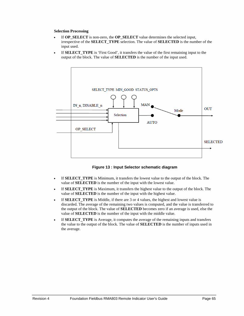
Revision 4 Foundation Fieldbus RMA803 Remote Indicator User's Guide Page 65
Selection Processing • If OP_SELECT is non-zero, the OP_SELECT value determines the selected input,
irrespective of the SELECT_TYPE selection. The value of SELECTED is the number of the input used.
• If SELECT_TYPE is ‘First Good’, it transfers the value of the first remaining input to the output of the block. The value of SELECTED is the number of the input used.
Figure 13 : Input Selector schematic diagram
• If SELECT_TYPE is Minimum, it transfers the lowest value to the output of the block. The
value of SELECTED is the number of the input with the lowest value. • If SELECT_TYPE is Maximum, it transfers the highest value to the output of the block. The
value of SELECTED is the number of the input with the highest value. • If SELECT_TYPE is Middle, if there are 3 or 4 values, the highest and lowest value is
discarded. The average of the remaining two values is computed, and the value is transferred to the output of the block. The value of SELECTED becomes zero if an average is used, else the value of SELECTED is the number of the input with the middle value.
• If SELECT_TYPE is Average, it computes the average of the remaining inputs and transfers the value to the output of the block. The value of SELECTED is the number of inputs used in the average.

Page 66 Foundation Fieldbus RMA803 Remote Indicator User's Guide Revision 4
Parameters List Table 21: Input Selector block parameters
Parameter Description
ST_REV The revision level of the static data associated with the function block. The revision value increments each time a static parameter value in the block is changed.
TAG_DESC The user description of the application of the block.
STRATEGY Used to identify grouping of blocks. This data is not checked or processed by the block.
ALERT_KEY The identification number of the plant unit. This information may be used in the host for sorting alarms, etc.
MODE_BLK The Actual, Target, Permitted, and Normal modes of the block. Target: The mode to “go to” Actual: The mode the “block is currently in” Permitted: Allowed modes that target may take on Normal: Most common mode for target
BLOCK_ERR This parameter reflects the error status associated with the hardware or software components associated with a block. It is a bit string, so that multiple errors may be shown.
OUT The block output value and status.
OUT_RANGE High and low scale values, engineering units code, and number of digits to the right of the decimal point associated with OUT
GRANT_DENY Options for controlling access of host computers and local control panels to operating, tuning, and alarm parameters of the block. Not used by device.
STATUS_OPTIONS
It helps to select options for status handling and processing. The supported status option for the integrator block is: “Use Uncertain as Good”, “Uncertain if MAN mode.”
IN_1 The block input value and status.
IN_2 The block input value and status.
IN_3 The block input value and status.
IN_4 The block input value and status.
INP_5 The block input value and status.
INP_6 The block input value and status.
INP_7 The block input value and status.
INP_8 The block input value and status.
DISABLE_1 Parameter to switch off the input from being used. 0-Use, 1 -Disable.
DISABLE_2 Parameter to switch off the input from being used. 0-Use, 1 -Disable.
DISABLE_3 Parameter to switch off the input from being used. 0-Use, 1 -Disable.
DISABLE_4 Parameter to switch off the input from being used. 0-Use, 1 -Disable.
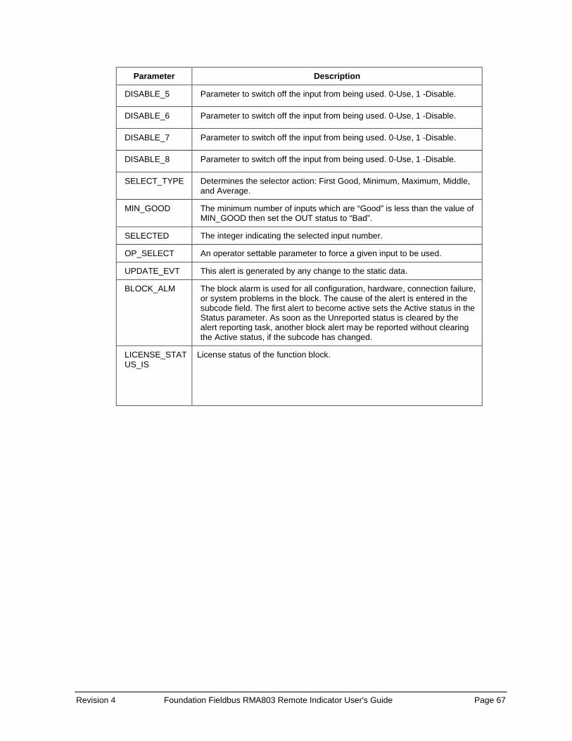
Revision 4 Foundation Fieldbus RMA803 Remote Indicator User's Guide Page 67
Parameter Description
DISABLE_5 Parameter to switch off the input from being used. 0-Use, 1 -Disable.
DISABLE_6 Parameter to switch off the input from being used. 0-Use, 1 -Disable.
DISABLE_7 Parameter to switch off the input from being used. 0-Use, 1 -Disable.
DISABLE_8 Parameter to switch off the input from being used. 0-Use, 1 -Disable.
SELECT_TYPE Determines the selector action: First Good, Minimum, Maximum, Middle, and Average.
MIN_GOOD The minimum number of inputs which are “Good” is less than the value of MIN_GOOD then set the OUT status to “Bad”.
SELECTED The integer indicating the selected input number.
OP_SELECT An operator settable parameter to force a given input to be used.
UPDATE_EVT This alert is generated by any change to the static data.
BLOCK_ALM The block alarm is used for all configuration, hardware, connection failure, or system problems in the block. The cause of the alert is entered in the subcode field. The first alert to become active sets the Active status in the Status parameter. As soon as the Unreported status is cleared by the alert reporting task, another block alert may be reported without clearing the Active status, if the subcode has changed.
LICENSE_STATUS_IS
License status of the function block.
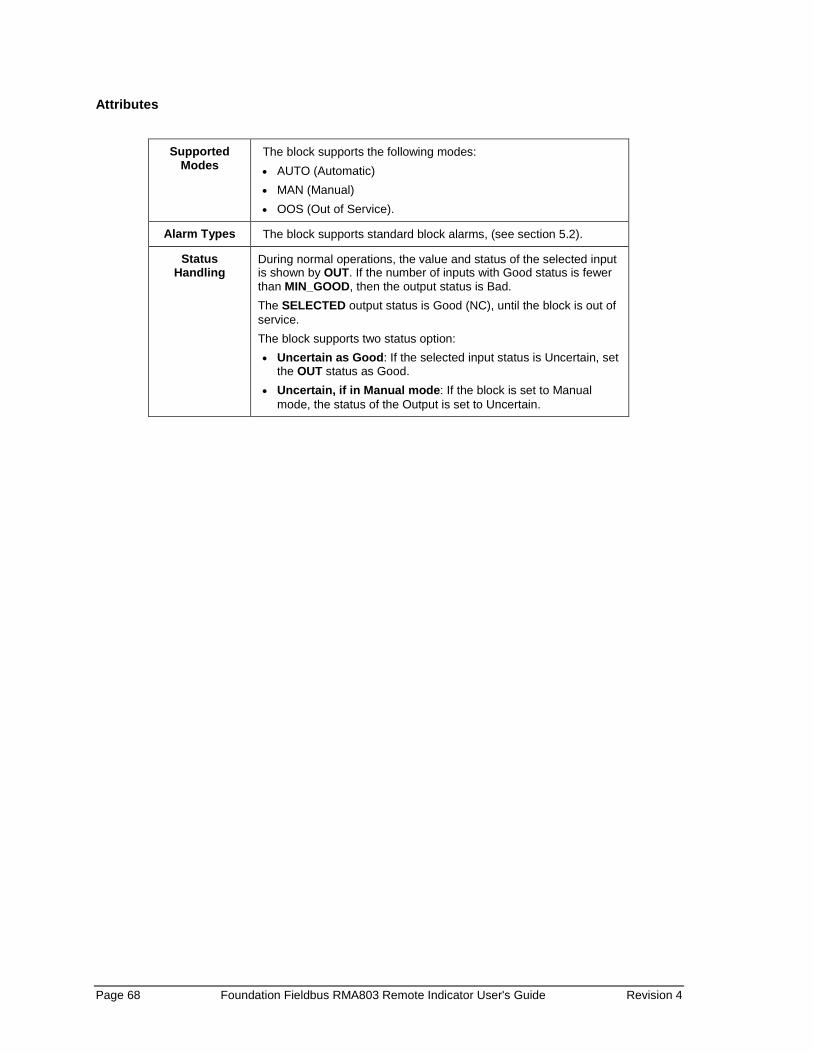
Page 68 Foundation Fieldbus RMA803 Remote Indicator User's Guide Revision 4
Attributes
Supported Modes
The block supports the following modes: • AUTO (Automatic) • MAN (Manual) • OOS (Out of Service).
Alarm Types The block supports standard block alarms, (see section 5.2).
Status Handling
During normal operations, the value and status of the selected input is shown by OUT. If the number of inputs with Good status is fewer than MIN_GOOD, then the output status is Bad. The SELECTED output status is Good (NC), until the block is out of service. The block supports two status option: • Uncertain as Good: If the selected input status is Uncertain, set
the OUT status as Good. • Uncertain, if in Manual mode: If the block is set to Manual
mode, the status of the Output is set to Uncertain.

Revision 4 Foundation Fieldbus RMA803 Remote Indicator User's Guide Page 69
5.8 Integrator block The Integrator block integrates a variable as a function of time, and also accumulates the counts from a Pulse Input block. The block is used as a totalizer that counts up until reset or as a batch totalizer that has a setpoint, and the integrated or accumulated value is compared to pre-trip and trip settings. When the pre-trip and trip settings are reached, the block generates discrete signals. The integrated value can go up, starting from zero, or go down, starting from the trip value depending on the settings. The block has two flow inputs to calculate and integrate net flow, which can be used to calculate volume or mass variation in vessels or as an optimizing tool for flow ratio control. The block does not support process alarms.
ATTENTION Alternatively IN_1 and IN_2 can be used as pulse inputs coming from other blocks. The same general rules for integration applies for the accumulation of pulses.
Figure 14: Integrator Block
Execution The basic function of the Integrator block is to integrate an analog value over time. It can also accumulate the pulses coming from the Pulse Input block or from other Integrator blocks. The block is normally used to totalize flow, giving total mass or volume over a certain time, or totalize power, giving the total energy. Inputs The block has two inputs: IN_1 and IN_2. If IN_2 is not connected (does not have a corresponding link object), calculations for IN_2 can be avoided. Each input can be configured to receive a measurement per unit of time (rate).
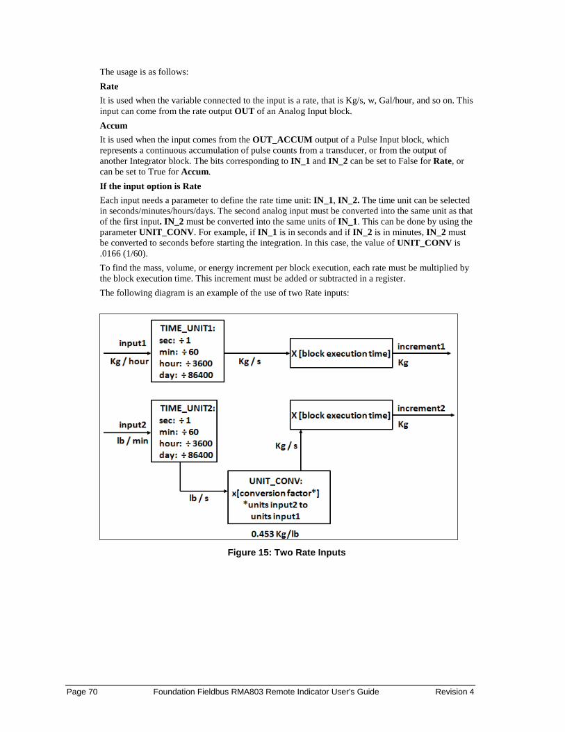
Page 70 Foundation Fieldbus RMA803 Remote Indicator User's Guide Revision 4
The usage is as follows: Rate It is used when the variable connected to the input is a rate, that is Kg/s, w, Gal/hour, and so on. This input can come from the rate output OUT of an Analog Input block. Accum It is used when the input comes from the OUT_ACCUM output of a Pulse Input block, which represents a continuous accumulation of pulse counts from a transducer, or from the output of another Integrator block. The bits corresponding to IN_1 and IN_2 can be set to False for Rate, or can be set to True for Accum. If the input option is Rate Each input needs a parameter to define the rate time unit: IN_1, IN_2. The time unit can be selected in seconds/minutes/hours/days. The second analog input must be converted into the same unit as that of the first input. IN_2 must be converted into the same units of IN_1. This can be done by using the parameter UNIT_CONV. For example, if IN_1 is in seconds and if IN_2 is in minutes, IN_2 must be converted to seconds before starting the integration. In this case, the value of UNIT_CONV is .0166 (1/60). To find the mass, volume, or energy increment per block execution, each rate must be multiplied by the block execution time. This increment must be added or subtracted in a register. The following diagram is an example of the use of two Rate inputs:
Figure 15: Two Rate Inputs

Revision 4 Foundation Fieldbus RMA803 Remote Indicator User's Guide Page 71
If the input option is Accum The Integrator block determines the number of additional counts from the counter input readings from the last execution. The difference in count is determined as follows: • If the difference between the reading in one cycle and the reading in the preceding cycle is less
than 500,000 or greater than (- 500,000), the difference must be taken as the variation. • If the difference between the reading in one cycle and the reading in the preceding cycle is
greater than or equal to (+500,000), add (-1,000,000), use the result as the variation. • If the difference between the reading in one cycle and the reading in the preceding cycle is more
negative than or equal to (-500,000), add (+1,000,000), use the result as the variation. The variation of each input must be multiplied by the value, in engineering units, of each pulse given by PULSE_VAL1 or PULSE_VAL2, as appropriate. The result is the increment in engineering units of, for example, mass, volume or energy per block execution. Net Flow The Net Flow is calculated by considering the direction of flow. The direction of the flow is calculated by selecting the parameters REV_FLOW and REV_FLOW2. When the status is set to True for any of these two parameters, the direction of the flow for that input is considered (Increment is negative) to be negative and the net flow is calculated by adding the increments for that cycle of execution. In order to integrate the difference between the inflow and outflow of a tank, for example, the second one can be assigned to be negative. The Net Flow direction to be considered in the totalization is defined in INTEG_OPTS. The following options are available: • FORWARD = Only positive flows (after application of REV_FLOWi) are totalized. The
negative values must be treated as zero. FORWARD is selected when the bit corresponding to Forward is set to True.
• REVERSE = Only negative flows are totalized. The positive values must be treated as zero. The option bit Reverse must be set to True.
Page 72 Foundation Fieldbus RMA803 Remote Indicator User's Guide Revision 4
Integration of Inputs There are three internal registers used for the totalization: • Total = The net increment is added every cycle, irrespective of the status. • Atotal = The absolute value of the net increment is added every cycle, irrespective of status. • Rtotal = The absolute value of the net increments with status as Bad (rejects) are added to this
register. The most significant part of Total can be read in the output OUT, and of Rtotal in RTOTAL. OUT_RANGE is used only for display of the totals by a host. The high and low range values of OUT_RANGE have no effect on the block. Types of Integration The value of OUT can start from zero and go up or it can start from a Setpoint value (TOTAL_SP) and go down. The Reset option can be automatic, periodic, or on demand. This is defined by the enumerated parameter INTEG_TYPE: • UP_AUTO – It counts up with automatic reset when TOTAL_SP is reached • UP_DEM – It counts up with demand reset, and the block resets only when the operator resets
the block. • DN_AUTO – The block is reset when the output becomes zero. The integration starts as SP and
increments are subtracted from the SP. • DN_DEM – The output is calculated even beyond zero till the block is reset. The integration
starts from SP. • PERIODIC – The integration is done for the assigned period (specified in seconds in
CLOCK_PER). After that period, the block is reset automatically. • DEMAND – The integration is done (positive or negative depending on the direction of the
flow) until the block is reset. • PER&DEM – It is a combination of periodic and demand types. The integration is carried till
the end of the specified period and after that period is automatically reset. The block can be reset at any time, before the end of periodic data set.
The first four types indicate use as a batch totalizer with a setpoint TOTAL_SP. The count does not stop at TOTAL_SP going up or zero going down, as it is important to get the True total of flow. Two outputs, OUT_TRIP and OUT_PTRIP, are associated with the four types. The next three types indicate that TOTAL_SP and the trip outputs are not used. The Periodic type (5) disables reset action based on RESET_IN, but has no impact on OP_CMD_INT. The internal registers always add the net increments. Counting down is done by setting OUT to the value of TOTAL_SP minus the most significant part of Total.
Revision 4 Foundation Fieldbus RMA803 Remote Indicator User's Guide Page 73
Resetting the totals The block uses a discrete input RESET_IN to reset the internal integration registers. The operator can send a command to reset the same registers by making OP_CMD_INT = RESET. This is a momentary switch that turns-off when the block is evaluated. The option “Confirm Reset” in INTEG_OPTS, if set, prevents another reset from occurring until the value 1 has been written to RESET_CONFIRM. This is an input that behaves like a momentary dynamic parameter if it is not connected.
The number of resets is counted in the register N_RESET. This counter cannot be written or reset. It provides verification that the total has not been reset since N_RESET was last checked. The counter must roll over from 999999 to 0. The reset always clears the internal registers Total, Atotal, and Rtotal, except that when the option UP_AUTO or DN_AUTO is selected, a residual value beyond the trip value may be carried to the next integration if the option Carry is set in INTEG_OPTS. In this case, TOTAL_SP is subtracted from Total, leaving the residual value. Batch totalizer outputs When the integration is counting up (type 1 or 2) and the value of OUT equals or exceeds a value given by TOTAL_SP minus PRE_TRIP, the discrete output OUT_PTRIP is set. When it equals or exceeds a value given by the parameter TOTAL_SP, the discrete output OUT_TRIP is set. OUT_PTRIP remains set. When the integration is counting down (type 3 or 4), it starts from a value given by TOTAL_SP. When the value of OUT is equal to or less than PRE_TRIP, the discrete output OUT_PTRIP is set. When the count reaches zero, the discrete output OUT_TRIP is set. OUT_PTRIP remains set. When a reset occurs, the comparisons that set OUT_PTRIP and OUT_TRIP are no longer True; so they are cleared. OUT_TRIP shall remain set for five seconds after an automatic reset (type 1 or 3), if RESET_CONFIRM is not connected or the option to “Confirm Reset” in INTEG_OPTS is not set. To determine the amount of Uncertain or Bad readings, the block integrates the variables with Bad, or Bad and Uncertain status separately. The values used in this second integration are the values with Good status, just before the status changed from Good to Bad or Good to Uncertain. The ratio of Good to total counts determines the output status. Absolute values are used to avoid problems with changing signs.
Integration options Any or all of the following integration options can be selected: INTEG_OPTS: 0 (Input1 Accumulate) When this option is selected, the accumulation of pulses is done instead of the rate input, integration. INTEG_OPTS: 0 (Input2 Accumulate) When this option is selected, the accumulation of pulses is done instead of the rate input, integration. Note: One input for rate and input for Accumulation can be selected. INTEG_OPTS: 0 (Flow forward) When this option is selected, only positive flows is considered for integration. If there is no forward flow inputs (whose value is positive value), and if one inputs is negative (whose value is positive value) the integration continues. Note: If both the inputs are negative, then the integration stops. INTEG_OPTS: 0 (Flow reverse)

Page 74 Foundation Fieldbus RMA803 Remote Indicator User's Guide Revision 4
When this option is selected, only reverse flows is considered for integration. If there is no reverse flow inputs (whose value is negative), and if one inputs is forward (whose value is positive) the integration continues. Note: If both the inputs are forward, then the integration stops. INTEG_OPTS: 0 (Use uncertain) When this option is selected, the input (IN_1/IN_2) whose status is Uncertain is considered for integration. INTEG_OPTS: 0 (Use Bad) When this option is selected, the input (IN_1/IN_2) whose status is Bad is considered for integration. INTEG_OPTS: 0 (Carry) This option is used only for UP_AUTO and DN_AUTO kind of integrations only. When this option is selected, the residual value after the integration is added / subtracted from the integral value in the next cycle of integration. INTEG_OPTS: 0 (Add Zero if Bad) When this option is selected, if IN_1/IN_2 is bad, the input value is zero for that input and integration does not happen. Integration stops at the last value. INTEG_OPTS: 0 (Confirm reset) This option is to be selected in conjunction with RESET_CONFIRM.VALUE. When the value of RESET_CONFIRM.VALUE is 1, and “Confirm Reset” is selected, the block gets reset. This is not applicable to UP_AUTO and DN_AUTO types.

Revision 4 Foundation Fieldbus RMA803 Remote Indicator User's Guide Page 75
Parameters List
Table 22: Integrator block parameters
Parameter Description
ST_REV The revision level of the static data associated with the function block.
TAG_DESC The user description of the application of the block.
STRATEGY Used to identify grouping of blocks. This data is not checked of processed by the block.
ALERT_KEY The identification number of the plant unit. This information may be used in the host for sorting alarms.
MODE_BLK The actual, target, permitted, ad normal modes of the block. Target: The mode to “go to” Actual: The mode the “block is currently in” Permitted: Allowed modes that target may take Normal: Most common mode for target.
BLOCK_ERR The summary of active error conditions associated with the block. The block error for the Integrator function block is Out of service.
TOTAL_SP The set point for a batch totalization.
OUT The block output value and status.
OUT_RANGE The high and low scale values, engineering units code, and number of digits to the right of the decimal point associated with OUT.
GRAND_DENY Options for controlling access of host computers and local control panels to operating, tuning, and alarm parameters of the block (not used by the device).
STATUS_OPTS It helps to select option for status handling and processing. The supported status options for the Integrator block are: “Uncertain if Manual mode.”
IN_1 The block input value and status.
IN_2 The block input value and status.
OUT_TRIP The first discrete output.
OUT_PTRIP The second discrete output.
TIME_UNIT1 Converts the rate time, units in seconds.
TIME_UNIT2 Converts the rate time, units in seconds.
UNIT_CONV Factor to convert the engineering units of IN_2 into the engineering units of IN_1.
PULSE_VAL1 Determines the mass, volume or energy per pulse.
PULSE_VAL2 Determines the mass, volume or energy per pulse.
REV_FLOW1 Indicates reverse flow when “True”; 0-Forward, 1-Reverse
REV_FLOW2 Indicates reverse flow when “True”; 0-Forward, 1-Reverse
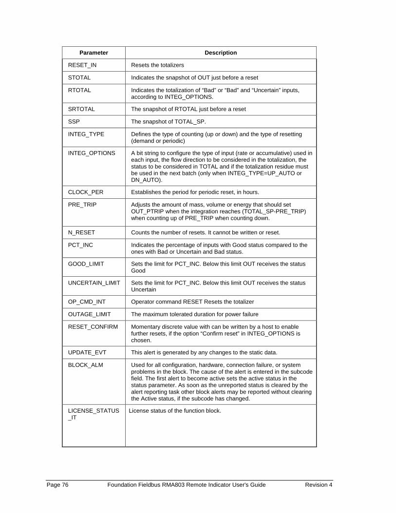
Page 76 Foundation Fieldbus RMA803 Remote Indicator User's Guide Revision 4
Parameter Description
RESET_IN Resets the totalizers
STOTAL Indicates the snapshot of OUT just before a reset
RTOTAL Indicates the totalization of “Bad” or “Bad” and “Uncertain” inputs, according to INTEG_OPTIONS.
SRTOTAL The snapshot of RTOTAL just before a reset
SSP The snapshot of TOTAL_SP.
INTEG_TYPE Defines the type of counting (up or down) and the type of resetting (demand or periodic)
INTEG_OPTIONS A bit string to configure the type of input (rate or accumulative) used in each input, the flow direction to be considered in the totalization, the status to be considered in TOTAL and if the totalization residue must be used in the next batch (only when INTEG_TYPE=UP_AUTO or DN_AUTO).
CLOCK_PER Establishes the period for periodic reset, in hours.
PRE_TRIP Adjusts the amount of mass, volume or energy that should set OUT_PTRIP when the integration reaches (TOTAL_SP-PRE_TRIP) when counting up of PRE_TRIP when counting down.
N_RESET Counts the number of resets. It cannot be written or reset.
PCT_INC Indicates the percentage of inputs with Good status compared to the ones with Bad or Uncertain and Bad status.
GOOD_LIMIT Sets the limit for PCT_INC. Below this limit OUT receives the status Good
UNCERTAIN_LIMIT Sets the limit for PCT_INC. Below this limit OUT receives the status Uncertain
OP_CMD_INT Operator command RESET Resets the totalizer
OUTAGE_LIMIT The maximum tolerated duration for power failure
RESET_CONFIRM Momentary discrete value with can be written by a host to enable further resets, if the option “Confirm reset” in INTEG_OPTIONS is chosen.
UPDATE_EVT This alert is generated by any changes to the static data.
BLOCK_ALM Used for all configuration, hardware, connection failure, or system problems in the block. The cause of the alert is entered in the subcode field. The first alert to become active sets the active status in the status parameter. As soon as the unreported status is cleared by the alert reporting task other block alerts may be reported without clearing the Active status, if the subcode has changed.
LICENSE_STATUS_IT
License status of the function block.

Revision 4 Foundation Fieldbus RMA803 Remote Indicator User's Guide Page 77
Attributes
Supported Modes
The block supports the following modes: • AUTO (Automatic) • MAN (Manual) • OOS (Out of Service).
Alarm Types The block supports standard block alarms, (see section 5.2).
Status Handling
If an input has status as Uncertain or Bad, then the limit status of the inputs is ignored, as is the sub status. Either Good(C) or Good (NC) is accepted as Good. The increment calculated from an input has an internal status that is either Good or Bad. If the input status is Good(C) or Good (NC), the increment status is Good. If the input status is Uncertain, the increment status is Bad, and the last Good value is used unless the option Use Uncertain is set in INTEG_OPTS, and then the increment status is Good and the new value is used. If the input status is Bad, the increment status is Bad, and the last Good value is used unless the option Use Bad is set in INTEG_OPTS, and then the increment status is Good and the last Good value is used. The two increments are added together, and the resulting status is the worst of the two. The option Add zero if Bad in INTEG_OPTS causes the net increment to be zero if its status is Bad. The percentage of Bad or Uncertain and Bad counts can be determined by calculating the value of PCT_INCL from Rtotal and Atotal. As Atotal is the sum of increments with Good and Bad status, and Rtotal is the sum of increments with Bad status, Atotal minus Rtotal is exactly equal to the total of increments with Good status. If most significant part (msp) and Atotal is not zero then the percent of Good values may be calculated as: PCT_INCL = 100 * ( 1 - (msp of Rtotal) / (msp of Atotal) ) If Atotal is zero, then PCT_INCL shall be 100 if Rtotal is also zero or 0 if Rtotal is not zero. If the block mode is AUTO, if PCT_INCL ≥ GOOD_LIM, the status of OUT is Good, or else if PCT_INCL ≥ UNCERT_LIM, the status of OUT is Uncertain, or else the status of OUT is Bad. If the block mode is Manual, then the status of OUT, OUT_PTRIP, and OUT_TRIP is Good (NC) constant when then status option Uncertain, if MAN is not selected. If this status option is selected and the block mode is manual, then the status of these three outputs is for Uncertain constant, and no limits are applied to the output.
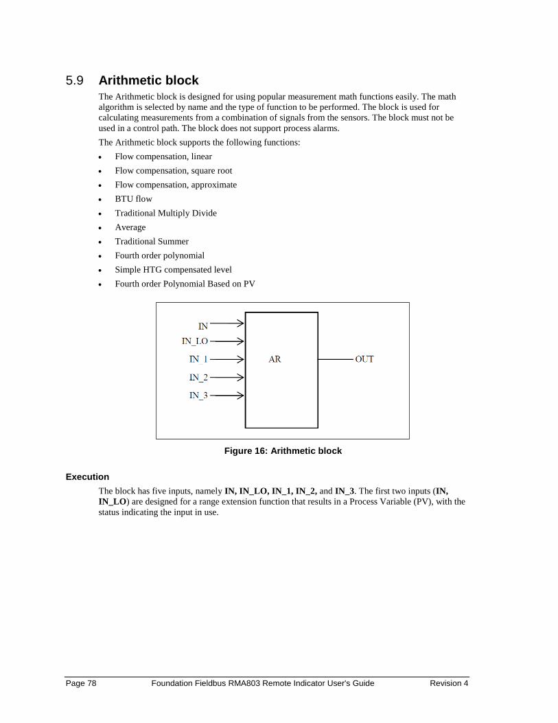
Page 78 Foundation Fieldbus RMA803 Remote Indicator User's Guide Revision 4
5.9 Arithmetic block The Arithmetic block is designed for using popular measurement math functions easily. The math algorithm is selected by name and the type of function to be performed. The block is used for calculating measurements from a combination of signals from the sensors. The block must not be used in a control path. The block does not support process alarms. The Arithmetic block supports the following functions: • Flow compensation, linear • Flow compensation, square root • Flow compensation, approximate • BTU flow • Traditional Multiply Divide • Average • Traditional Summer • Fourth order polynomial • Simple HTG compensated level • Fourth order Polynomial Based on PV
Figure 16: Arithmetic block
Execution
The block has five inputs, namely IN, IN_LO, IN_1, IN_2, and IN_3. The first two inputs (IN, IN_LO) are designed for a range extension function that results in a Process Variable (PV), with the status indicating the input in use.

Revision 4 Foundation Fieldbus RMA803 Remote Indicator User's Guide Page 79
Figure 17: Arithmetic schematic diagram
The remaining three inputs (IN_1, IN_2, and IN_3) are combined with the PV in a selection of four term math functions. To ensure that the PV enters the equation with the right units, the inputs used to form the PV must come from devices with the desired engineering units. Each additional input has a bias constant and gain constant. To correct Absolute Pressure, use the bias constant, and to normalize terms within a square root function, use the gain constant. Calculation of PV The range extension function has a graduated transfer controlled by two constants referenced to IN. An internal value, g, is zero for IN less than RANGE_LO. It is one when IN is greater than RANGE_HI. It is interpolated from zero to one over the range of RANGE_LO to RANGE_HI. The equation for PV follows:
𝑃𝑃𝑃𝑃 = 𝑔𝑔×𝐼𝐼𝐼𝐼 + (1 − 𝑔𝑔)×𝐼𝐼𝐼𝐼_𝐿𝐿𝐿𝐿 If the status of IN_LO is not usable and IN is usable and greater than RANGE_LO, then g is set to one. If the status of IN is unusable, and IN_LO is usable and less than RANGE_HI, then g is set to zero.
For three auxiliary inputs, six constants are used, and each input has a BIAS_IN_i and a GAIN_IN_i. The output has a BIAS and a GAIN static constant. For the inputs, the bias is added, and the gain is applied to the sum. The result is an internal value called t_i in the function equations. The equation for each auxiliary input is the following:
𝑡𝑡_𝑖𝑖 = (𝐼𝐼𝐼𝐼_𝑖𝑖 + 𝐵𝐵𝐼𝐼𝐵𝐵𝐵𝐵_𝐼𝐼𝐼𝐼_𝑖𝑖)×𝐺𝐺𝐵𝐵𝐼𝐼𝐼𝐼_𝐼𝐼𝐼𝐼_𝑖𝑖 If an auxiliary input is unstable, to assure smooth degradation, the flow compensation functions have limits on the amount of compensation applied to the PV. The internal limited value is f. The following function types are supported: 1. Flow compensation, linear. Used for density compensation of volume flow.
𝑓𝑓𝑓𝑓𝑓𝑓𝑓𝑓 = 𝑓𝑓×𝑃𝑃𝑃𝑃
𝑓𝑓 =(𝑡𝑡_1)(𝑡𝑡_2)
× [𝑙𝑙𝑖𝑖𝑙𝑙𝑖𝑖𝑡𝑡𝑙𝑙𝑙𝑙]

Page 80 Foundation Fieldbus RMA803 Remote Indicator User's Guide Revision 4
2. Flow compensation, square root. Usually, IN_1 is pressure, IN_2 temperature, and IN_3 is the compressibility factor Z.
𝑓𝑓𝑓𝑓𝑓𝑓𝑓𝑓 = 𝑓𝑓×𝑃𝑃𝑃𝑃
𝑓𝑓 = �(𝑡𝑡_1)(𝑡𝑡_2)(𝑡𝑡_3)
× [𝑙𝑙𝑖𝑖𝑙𝑙𝑖𝑖𝑡𝑡𝑙𝑙𝑙𝑙]
3. Flow compensation, approximate. Both IN_2 and IN_3 would be connected to the same temperature.
𝑓𝑓𝑓𝑓𝑓𝑓𝑓𝑓 = 𝑓𝑓×𝑃𝑃𝑃𝑃
𝑓𝑓 = �(𝑡𝑡_1)×(𝑡𝑡_2)×(𝑡𝑡_3)×(𝑡𝑡_3) × [𝑙𝑙𝑖𝑖𝑙𝑙𝑖𝑖𝑡𝑡𝑙𝑙𝑙𝑙] 4. BTU flow, where IN_1 is inlet temperature, and IN_2 the outlet temperature.
𝑓𝑓𝑓𝑓𝑓𝑓𝑓𝑓 = 𝑓𝑓×𝑃𝑃𝑃𝑃 𝑓𝑓 = (𝑡𝑡_1 − 𝑡𝑡_2) × [𝑙𝑙𝑖𝑖𝑙𝑙𝑖𝑖𝑡𝑡𝑙𝑙𝑙𝑙]
5. Traditional Multiply Divide 𝑓𝑓𝑓𝑓𝑓𝑓𝑓𝑓 = 𝑓𝑓×𝑃𝑃𝑃𝑃
𝑓𝑓 =(𝑡𝑡_1)(𝑡𝑡_2)
+ (𝑡𝑡_3)× [𝑙𝑙𝑖𝑖𝑙𝑙𝑖𝑖𝑡𝑡𝑙𝑙𝑙𝑙]
6. Average
𝑓𝑓𝑓𝑓𝑓𝑓𝑓𝑓 =(𝑃𝑃𝑃𝑃 + (𝑡𝑡_1) + (𝑡𝑡_2) + (𝑡𝑡_3))
𝑓𝑓
f = number of inputs used in computation (unusable inputs are not used). 7. Traditional Summer
𝑓𝑓𝑓𝑓𝑓𝑓𝑓𝑓 = 𝑃𝑃𝑃𝑃 + (𝑡𝑡_1) + (𝑡𝑡_2) + (𝑡𝑡_3) 8. Fourth order polynomial. All inputs except IN_LO (not used) are linked together.
𝑓𝑓𝑓𝑓𝑓𝑓𝑓𝑓 = PV + (𝑡𝑡_1)2 + (𝑡𝑡_2)3 + (𝑡𝑡_3)4
9. Simple HTG compensated level, where PV is the tank base pressure, IN_1 is the top pressure, IN_2 is the density correction pressure, and GAIN is the height of the density tap.
𝑓𝑓𝑓𝑓𝑓𝑓𝑓𝑓 =(𝑃𝑃𝑃𝑃 − (𝑡𝑡_1))(𝑃𝑃𝑃𝑃 − (𝑡𝑡_2))
10. Fourth order polynomial based on PV 𝑓𝑓𝑓𝑓𝑓𝑓𝑓𝑓 = PV + GAIN_IN_1×(𝑃𝑃𝑃𝑃)2 + GAIN_IN_2×(𝑃𝑃𝑃𝑃)3+ GAIN_IN_3×(𝑃𝑃𝑃𝑃)4
After the value of func is calculated, it is multiplied by GAIN, and then BIAS is added to the result. Then, the high and low output limits are applied as per configured range scaling, and PRE_OUT is updated with the calculated value. If the mode is AUTO, PRE_OUT is copied to OUT.
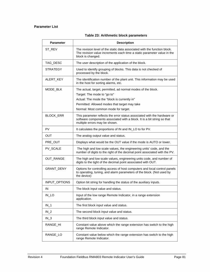
Revision 4 Foundation Fieldbus RMA803 Remote Indicator User's Guide Page 81
Parameter List
Table 23: Arithmetic block parameters
Parameter Description
ST_REV The revision level of the static data associated with the function block. The revision value increments each time a static parameter value in the block is changed.
TAG_DESC The user description of the application of the block.
STRATEGY Used to identify grouping of blocks. This data is not checked of processed by the block.
ALERT_KEY The identification number of the plant unit. This information may be used in the host for sorting alarms, etc.
MODE_BLK The actual, target, permitted, ad normal modes of the block. Target: The mode to “go to” Actual: The mode the “block is currently in” Permitted: Allowed modes that target may take Normal: Most common mode for target.
BLOCK_ERR This parameter reflects the error status associated with the hardware or software components associated with a block. It is a bit string so that multiple errors may be shown.
PV It calculates the proportions of IN and IN_LO to for PV.
OUT The analog output value and status.
PRE_OUT Displays what would be the OUT value if the mode is AUTO or lower.
PV_SCALE The high and low scale values, the engineering units’ code, and the number of digits to the right of the decimal point associated with the PV.
OUT_RANGE The high and low scale values, engineering units code, and number of digits to the tight of the decimal point associated with OUT.
GRANT_DENY Options for controlling access of host computers and local control panels to operating, tuning, and alarm parameters of the block. (Not used by the device)
INPUT_OPTIONS Option bit string for handling the status of the auxiliary inputs.
IN The block input value and status.
IN_LO Input of the low range Remote Indicator, in a range extension application.
IN_1 The first block input value and status.
IN_2 The second block input value and status.
IN_3 The third block input value and status.
RANGE_HI Constant value above which the range extension has switch to the high range Remote Indicator.
RANGE_LO Constant value below which the range extension has switch to the high range Remote Indicator.
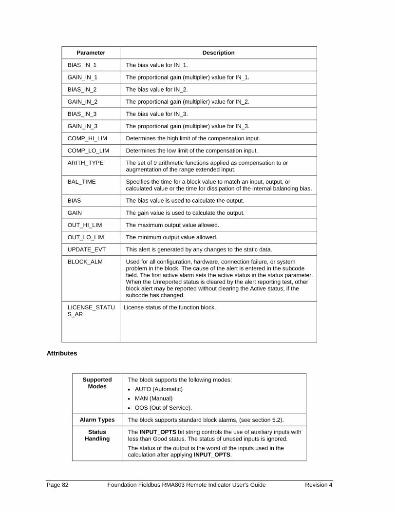
Page 82 Foundation Fieldbus RMA803 Remote Indicator User's Guide Revision 4
Parameter Description
BIAS_IN_1 The bias value for IN_1.
GAIN_IN_1 The proportional gain (multiplier) value for IN_1.
BIAS_IN_2 The bias value for IN_2.
GAIN_IN_2 The proportional gain (multiplier) value for IN_2.
BIAS_IN_3 The bias value for IN_3.
GAIN_IN_3 The proportional gain (multiplier) value for IN_3.
COMP_HI_LIM Determines the high limit of the compensation input.
COMP_LO_LIM Determines the low limit of the compensation input.
ARITH_TYPE The set of 9 arithmetic functions applied as compensation to or augmentation of the range extended input.
BAL_TIME Specifies the time for a block value to match an input, output, or calculated value or the time for dissipation of the internal balancing bias.
BIAS The bias value is used to calculate the output.
GAIN The gain value is used to calculate the output.
OUT_HI_LIM The maximum output value allowed.
OUT_LO_LIM The minimum output value allowed.
UPDATE_EVT This alert is generated by any changes to the static data.
BLOCK_ALM Used for all configuration, hardware, connection failure, or system problem in the block. The cause of the alert is entered in the subcode field. The first active alarm sets the active status in the status parameter. When the Unreported status is cleared by the alert reporting test, other block alert may be reported without clearing the Active status, if the subcode has changed.
LICENSE_STATUS_AR
License status of the function block.
Attributes
Supported Modes
The block supports the following modes: • AUTO (Automatic) • MAN (Manual) • OOS (Out of Service).
Alarm Types The block supports standard block alarms, (see section 5.2).
Status Handling
The INPUT_OPTS bit string controls the use of auxiliary inputs with less than Good status. The status of unused inputs is ignored. The status of the output is the worst of the inputs used in the calculation after applying INPUT_OPTS.
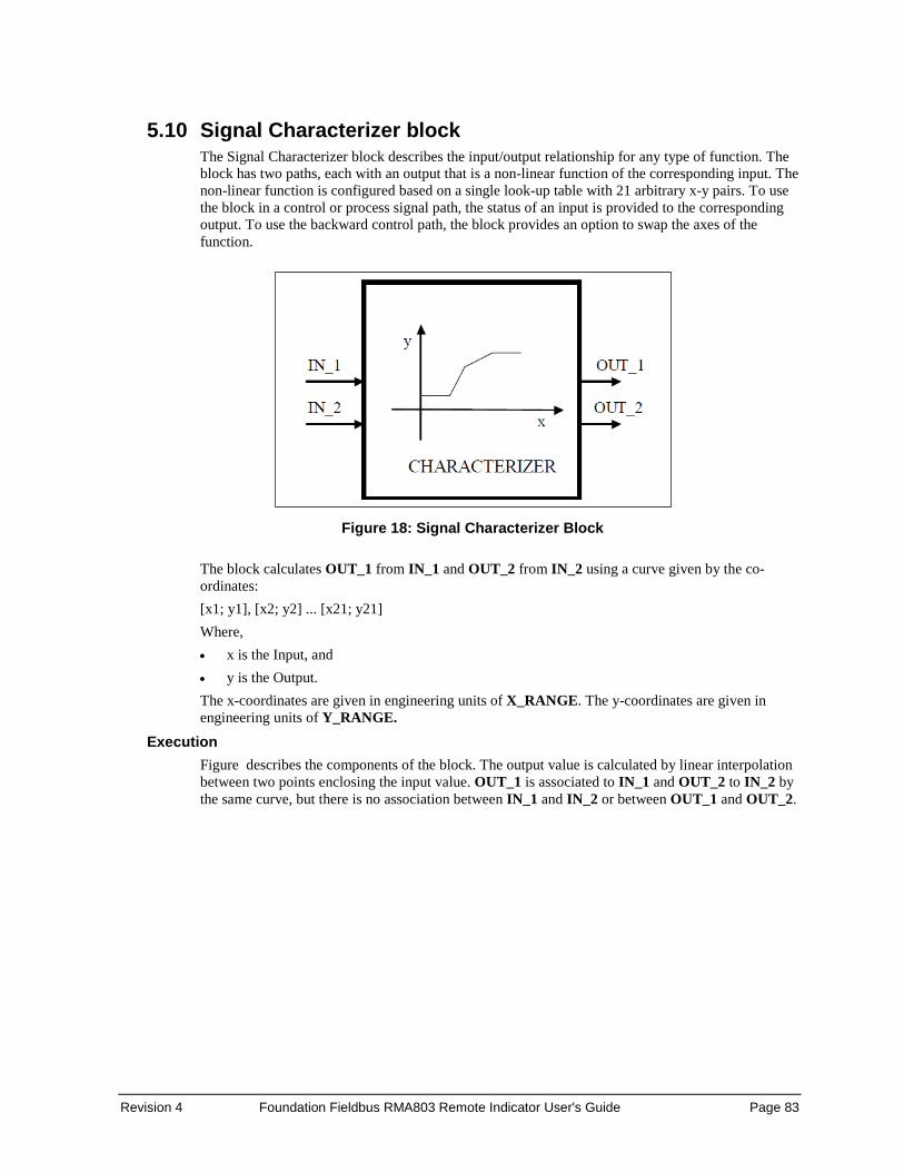
Revision 4 Foundation Fieldbus RMA803 Remote Indicator User's Guide Page 83
5.10 Signal Characterizer block The Signal Characterizer block describes the input/output relationship for any type of function. The block has two paths, each with an output that is a non-linear function of the corresponding input. The non-linear function is configured based on a single look-up table with 21 arbitrary x-y pairs. To use the block in a control or process signal path, the status of an input is provided to the corresponding output. To use the backward control path, the block provides an option to swap the axes of the function.
Figure 18: Signal Characterizer Block
The block calculates OUT_1 from IN_1 and OUT_2 from IN_2 using a curve given by the co-ordinates: [x1; y1], [x2; y2] ... [x21; y21] Where, • x is the Input, and • y is the Output. The x-coordinates are given in engineering units of X_RANGE. The y-coordinates are given in engineering units of Y_RANGE.
Execution Figure describes the components of the block. The output value is calculated by linear interpolation between two points enclosing the input value. OUT_1 is associated to IN_1 and OUT_2 to IN_2 by the same curve, but there is no association between IN_1 and IN_2 or between OUT_1 and OUT_2.

Page 84 Foundation Fieldbus RMA803 Remote Indicator User's Guide Revision 4
To derive the output value that corresponds to the input, use the following formula, y = mx + c
Where, • m is the slope of the line. • c is the y-intercept of the line
Figure 19: Signal characterizer curve
The values of x must increase sequentially for interpolation to be applicable. If not, a configuration error is set in BLOCK_ERR, and the Actual mode of the block goes to Out of Service mode. If the curve has m points, m<21, the non-configured points, [xm+1; ym+1], [xm+2; ym+2], ... [x21; y21] is set to +INFINITY to mark them as unused. Since x1 is the smallest specified value for the input and xm is the largest, the output is at y1 when the input is smaller than x1, and the output is at ym when the input is larger than xm. Since the ends of the y curve act as limits, the OUT status is shown when either limit is active. Backward Control path A reverse function swaps the interpretation of IN_2 and OUT_2 that provides a way to do reverse calculation using the same curve. If the parameter SWAP_2 is set to True, the block provides: IN_1 = x and OUT_1 = y while IN_2 = y and OUT_2 = x If the function is not sequential in y and SWAP_2 is True, BLOCK_ERR indicates a configuration error, and the Actual mode goes to Out of Service mode for x. A function is said to be sequential when y values always increase or decrease when x values increase. If SWAP_2 = False, IN_1 and IN_2 have the same engineering units defined in X_RANGE and OUT_1 and OUT_2 use the units defined in Y_RANGE. If SWAP_2 = True, OUT _1 and IN_2 have Y_RANGE and OUT_2 and IN_1 have X_RANGE.

Revision 4 Foundation Fieldbus RMA803 Remote Indicator User's Guide Page 85
Parameter list
Table 24: Signal Characterizer block parameters
Parameter Description
ST_REV The revision level of the static data associated with the function block. The revision value is incremented each time a static parameter value in the block is changed.
TAG_DESC The use description of the intended application of the block.
STRATEGY The strategy field can be used to identify grouping of blocks. This data is not checked or processed by the block.
ALERT_KEY The identification number of the plant unit. This information may be used in the host for sorting alarms, etc.
MODE_BLK The actual, target, permitted, ad normal modes of the block. Target: The mode to “go to” Actual: The mode the “block is currently in” Permitted: Allowed modes that target may take on Normal: Most common mode for target
BLOCK_ERR This parameter reflects the error status associated with the hardware or software components associated with a block. It is a bit string so that multiple errors may be shown.
OUT_1 The block output value and status.
OUT_2 The block output value and status.
X_RANGE The display scaling of the variable corresponding to the x-axis for display. It has no effect on the block.
Y_RANGE The display scaling of the variable corresponding to the y-axis for display. It has no effect on the block.
GRANT_DENY Options for controlling access of host computers and local control panels to operating, tuning, and alarm parameters of the block. (Not used by the device)
IN_1 The block input value and status.
IN_2 The block input value and status.
SWAP_2 Changes the algorithm in such a way that IN_2 corresponds to “y” and OUT_2 to “x”.
CURVE_X Curve input points. The “x” points of the curve are defined by an array of 21 points.
CURVE_Y Curve input points. The “y” points of the curve are defined by an array of 21 points.
UPDATE_EVT This alert is generated by any changes to the static data.
BLOCK _ALM The block alarm is used for all configuration, hardware, connection failure, or system problems in the block. The cause of the alert is entered in the subcode field. The first alert to become active sets the active status in the status parameter. As soon as the Unreported status is cleared by the alert reporting task other block alerts may be reported without clearing the active status, if the subcode has changed.
LICENSE_STATUS_SC License status of the function block.
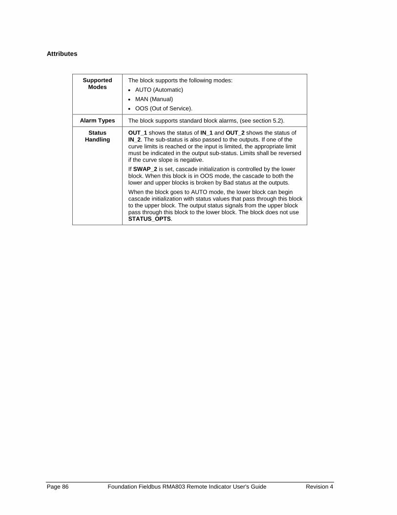
Page 86 Foundation Fieldbus RMA803 Remote Indicator User's Guide Revision 4
Attributes
Supported
Modes The block supports the following modes: • AUTO (Automatic) • MAN (Manual) • OOS (Out of Service).
Alarm Types The block supports standard block alarms, (see section 5.2).
Status Handling
OUT_1 shows the status of IN_1 and OUT_2 shows the status of IN_2. The sub-status is also passed to the outputs. If one of the curve limits is reached or the input is limited, the appropriate limit must be indicated in the output sub-status. Limits shall be reversed if the curve slope is negative. If SWAP_2 is set, cascade initialization is controlled by the lower block. When this block is in OOS mode, the cascade to both the lower and upper blocks is broken by Bad status at the outputs. When the block goes to AUTO mode, the lower block can begin cascade initialization with status values that pass through this block to the upper block. The output status signals from the upper block pass through this block to the lower block. The block does not use STATUS_OPTS.
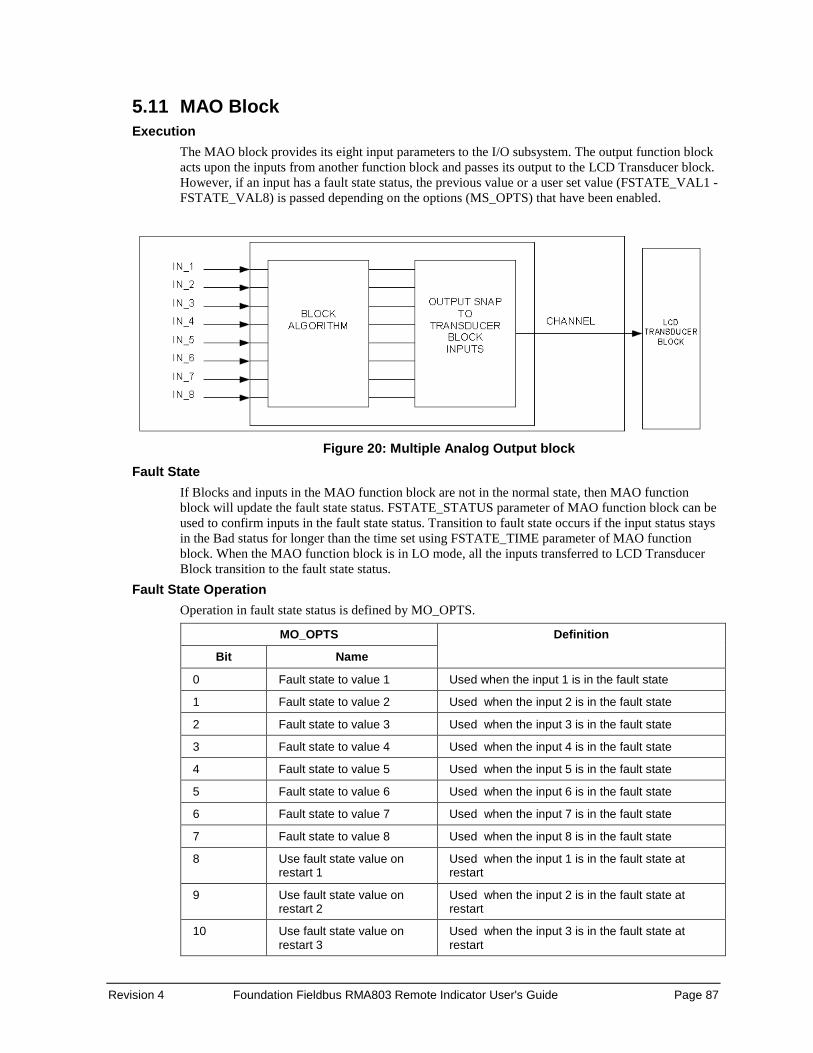
Revision 4 Foundation Fieldbus RMA803 Remote Indicator User's Guide Page 87
5.11 MAO Block Execution
The MAO block provides its eight input parameters to the I/O subsystem. The output function block acts upon the inputs from another function block and passes its output to the LCD Transducer block. However, if an input has a fault state status, the previous value or a user set value (FSTATE_VAL1 - FSTATE_VAL8) is passed depending on the options (MS_OPTS) that have been enabled.
Figure 20: Multiple Analog Output block
Fault State If Blocks and inputs in the MAO function block are not in the normal state, then MAO function block will update the fault state status. FSTATE_STATUS parameter of MAO function block can be used to confirm inputs in the fault state status. Transition to fault state occurs if the input status stays in the Bad status for longer than the time set using FSTATE_TIME parameter of MAO function block. When the MAO function block is in LO mode, all the inputs transferred to LCD Transducer Block transition to the fault state status.
Fault State Operation Operation in fault state status is defined by MO_OPTS.
MO_OPTS Definition
Bit Name
0 Fault state to value 1 Used when the input 1 is in the fault state
1 Fault state to value 2 Used when the input 2 is in the fault state
2 Fault state to value 3 Used when the input 3 is in the fault state
3 Fault state to value 4 Used when the input 4 is in the fault state
4 Fault state to value 5 Used when the input 5 is in the fault state
5 Fault state to value 6 Used when the input 6 is in the fault state
6 Fault state to value 7 Used when the input 7 is in the fault state
7 Fault state to value 8 Used when the input 8 is in the fault state
8 Use fault state value on restart 1
Used when the input 1 is in the fault state at restart
9 Use fault state value on restart 2
Used when the input 2 is in the fault state at restart
10 Use fault state value on restart 3
Used when the input 3 is in the fault state at restart
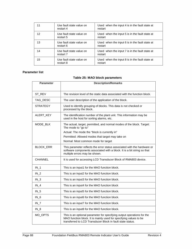
Page 88 Foundation Fieldbus RMA803 Remote Indicator User's Guide Revision 4
11 Use fault state value on restart 4
Used when the input 4 is in the fault state at restart
12 Use fault state value on restart 5
Used when the input 5 is in the fault state at restart
13 Use fault state value on restart 6
Used when the input 6 is in the fault state at restart
14 Use fault state value on restart 7
Used when the input 7 is in the fault state at restart
15 Use fault state value on restart 8
Used when the input 8 is in the fault state at restart
Parameter list Table 25: MAO block parameters
Parameter Description/Remarks
ST_REV The revision level of the static data associated with the function block.
TAG_DESC The user description of the application of the block.
STRATEGY Used to identify grouping of blocks. This data is not checked or processed by the block.
ALERT_KEY The identification number of the plant unit. This information may be used in the host for sorting alarms, etc.
MODE_BLK The actual, target, permitted, and normal modes of the block. Target: The mode to “go to” Actual: The mode the “block is currently in” Permitted: Allowed modes that target may take on Normal: Most common mode for target
BLOCK_ERR This parameter reflects the error status associated with the hardware or software components associated with a block. It is a bit string so that multiple errors may be shown.
CHANNEL It is used for accessing LCD Transducer Block of RMA803 device.
IN_1 This is an input1 for the MAO function block.
IN_2 This is an input2 for the MAO function block.
IN_3 This is an input3 for the MAO function block.
IN_4 This is an input4 for the MAO function block
IN_5 This is an input5 for the MAO function block.
IN_6 This is an input6 for the MAO function block.
IN_7 This is an input7 for the MAO function block.
IN_8 This is an input8 for the MAO function block.
MO_OPTS This is an optional parameter for specifying output operations for the MAO function block. It is mainly used for specifying values to be transferred to LCD Transducer Block in fault state status.
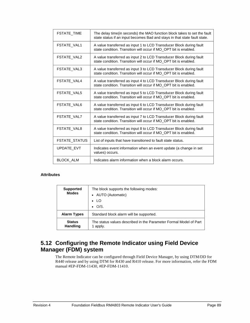
Revision 4 Foundation Fieldbus RMA803 Remote Indicator User's Guide Page 89
FSTATE_TIME The delay time(in seconds) the MAO function block takes to set the fault state status if an input becomes Bad and stays in that state fault state.
FSTATE_VAL1 A value transferred as input 1 to LCD Transducer Block during fault state condition. Transition will occur if MO_OPT bit is enabled.
FSTATE_VAL2 A value transferred as input 2 to LCD Transducer Block during fault state condition. Transition will occur if MO_OPT bit is enabled.
FSTATE_VAL3 A value transferred as input 3 to LCD Transducer Block during fault state condition. Transition will occur if MO_OPT bit is enabled.
FSTATE_VAL4 A value transferred as input 4 to LCD Transducer Block during fault state condition. Transition will occur if MO_OPT bit is enabled.
FSTATE_VAL5 A value transferred as input 5 to LCD Transducer Block during fault state condition. Transition will occur if MO_OPT bit is enabled.
FSTATE_VAL6 A value transferred as input 6 to LCD Transducer Block during fault state condition. Transition will occur if MO_OPT bit is enabled.
FSTATE_VAL7 A value transferred as input 7 to LCD Transducer Block during fault state condition. Transition will occur if MO_OPT bit is enabled.
FSTATE_VAL8 A value transferred as input 8 to LCD Transducer Block during fault state condition. Transition will occur if MO_OPT bit is enabled.
FSTATE_STATUS List of inputs that have transitioned to fault state status.
UPDATE_EVT Indicates event information when an event update (a change in set values) occurs.
BLOCK_ALM Indicates alarm information when a block alarm occurs.
Attributes
Supported Modes
The block supports the following modes: • AUTO (Automatic) • LO • O/S.
Alarm Types Standard block alarm will be supported.
Status Handling
The status values described in the Parameter Formal Model of Part 1 apply.
5.12 Configuring the Remote Indicator using Field Device Manager (FDM) system
The Remote Indicator can be configured through Field Device Manager, by using DTM/DD for R440 release and by using DTM for R430 and R410 release. For more information, refer the FDM manual #EP-FDM-11430, #EP-FDM-11410.

Page 90 Foundation Fieldbus RMA803 Remote Indicator User's Guide Revision 4
6. RMA803 FF Remote Indicator Operation 6.1 Operational considerations
There are a number of considerations that must be noted when configuring a Remote Indicator to operate in a fieldbus network.
LAS Capability The Remote Indicator is capable of operating as the Link Active Scheduler (LAS). The LAS is a fieldbus feature which controls traffic on the network, such as controlling token-rotation and coordinating data publishing. This fieldbus function is active in only one device at any given time on a network. Devices which can be designated as the LAS may be an operator station or a field device. The Remote Indicator can be designated as LAS, in the event of a failure of the primary LAS, control in the field could continue.
ATTENTION Note that the Remote Indicator can be used only as “backup” LAS.
Special Non-volatile parameters and NVM Wear-out
All function block parameters designated as Non-Volatile (NV) in the FF specifications are updated to non-volatile memory (NVM) on a periodic basis. NV_CYCLE_T parameter in the resource block specifies this update interval. To provide predictable restart behavior in the Remote Indicator, the following Non-Volatile parameters are updated to NVM each time they are written over the fieldbus. • MODE.TARGET for all blocks • SP.VALUE for the PID block Since these are user-written parameters, these additional updates to NVM contribute negligibly to NVM wear out. However, users are cautioned to not construct control configurations where the above parameters are written continuously (via a computer application for example) or at rates greater than the NV_CYCLE_T interval. This consideration helps to minimize the possibility of NVM wear-out. In the case of MODE this must not be a problem. When users wish to provide set-points to the PID block via a computer application, users should use RCAS mode with its corresponding set point value RCAS_IN. RCAS_IN is updated only at the NV_CYCLE_T update rate and this mode supports full shedding functionality and PID initialization necessary for a robust application.
Mode Restricted Writes to Parameters Some block parameters have restrictions on having write access to them. These are specified in the FF specifications. Writing to certain function block parameters are restricted based on the block’s Target and/ or Actual mode.
6.2 Configuration of the RMA803 Remote Indicator using Handheld (HH)
Figure 21 graphically represents the connection of the RMA803 Remote Indicator to the handheld. Each Remote Indicator includes a configuration database that stores its operating characteristics in a non-volatile memory. The handheld is used to establish and/or change selected operating parameters in a RMA803 Remote Indicator database. The process of viewing and/or changing database parameters is called configuration. Configuration can be accomplished both online and offline with the Remote Indicator powered up and connected to the handheld. The online configuration immediately changes the Remote Indicator operating parameters. For offline configuration, Remote Indicator operating characteristics are entered into the handheld memory for subsequent downloading to a Remote Indicator.
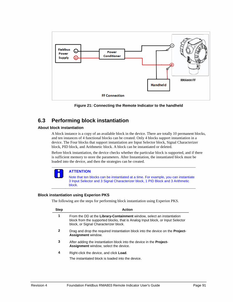
Revision 4 Foundation Fieldbus RMA803 Remote Indicator User's Guide Page 91
Figure 21: Connecting the Remote Indicator to the handheld
6.3 Performing block instantiation About block instantiation
A block instance is a copy of an available block in the device. There are totally 10 permanent blocks, and ten instances of 4 functional blocks can be created. Only 4 blocks support instantiation in a device. The Four blocks that support instantiation are Input Selector block, Signal Characterizer block, PID block, and Arithmetic block. A block can be instantiated or deleted. Before block instantiation, the device checks whether the particular block is supported, and if there is sufficient memory to store the parameters. After Instantiation, the instantiated block must be loaded into the device, and then the strategies can be created.
ATTENTION Note that ten blocks can be instantiated at a time. For example, you can instantiate 3 Input Selector and 3 Signal Characterizer block, 1 PID Block and 3 Arithmetic block.
Block instantiation using Experion PKS
The following are the steps for performing block instantiation using Experion PKS.
Step Action
1 From the DD at the Library-Containment window, select an instantiation block from the supported blocks, that is Analog Input block, or Input Selector block, or Signal Characterizer block.
2 Drag and drop the required instantiation block into the device on the Project-Assignment window.
3 After adding the instantiation block into the device in the Project-Assignment window, select the device.
4 Right-click the device, and click Load. The instantiated block is loaded into the device.
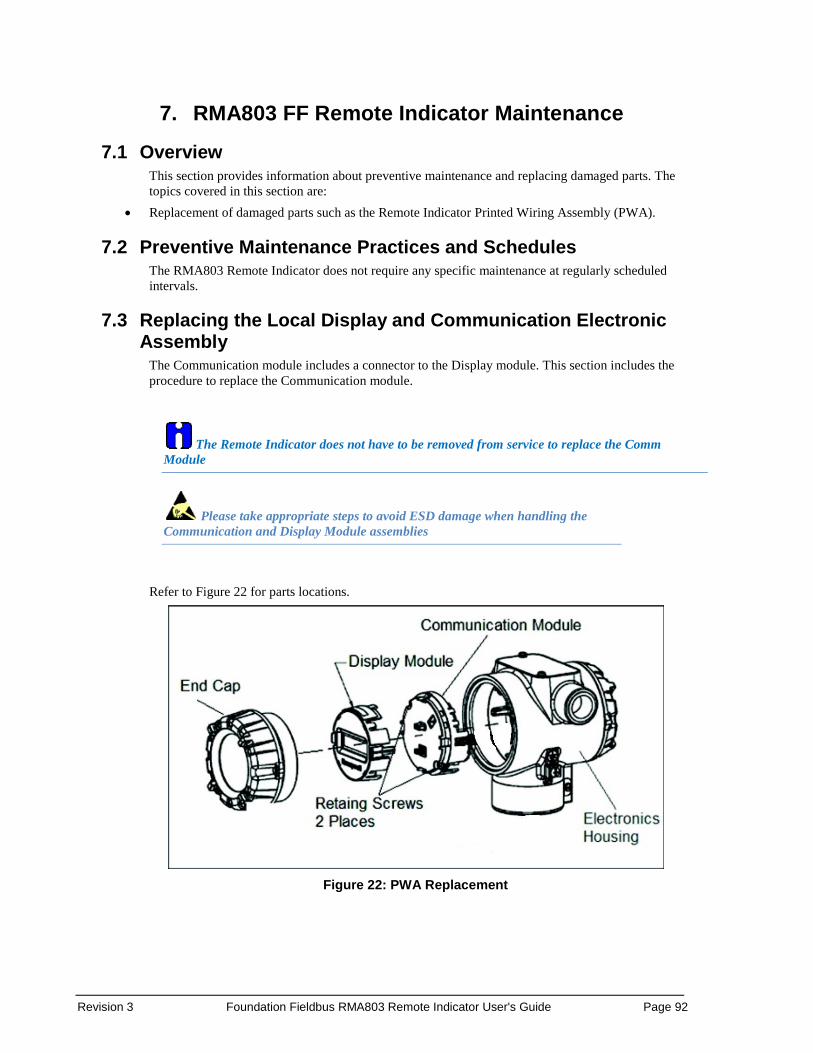
Revision 3 Foundation Fieldbus RMA803 Remote Indicator User's Guide Page 92
7. RMA803 FF Remote Indicator Maintenance 7.1 Overview
This section provides information about preventive maintenance and replacing damaged parts. The topics covered in this section are:
• Replacement of damaged parts such as the Remote Indicator Printed Wiring Assembly (PWA).
7.2 Preventive Maintenance Practices and Schedules The RMA803 Remote Indicator does not require any specific maintenance at regularly scheduled intervals.
7.3 Replacing the Local Display and Communication Electronic Assembly
The Communication module includes a connector to the Display module. This section includes the procedure to replace the Communication module.
The Remote Indicator does not have to be removed from service to replace the Comm Module
Please take appropriate steps to avoid ESD damage when handling the Communication and Display Module assemblies
Refer to Figure 22 for parts locations.
Figure 22: PWA Replacement

Revision 4 Foundation Fieldbus RMA803 Remote Indicator User's Guide Page 93
1. Turn OFF Remote Indicator power (Power removal is only required in accordance with area safety approvals. Power removal is only required in Class 1 Div 1 Explosionproof and Class 1 Div 2 environments).
• When removing the Communications Module with power applied, the loop will go to 0V. Likewise, installing a Communications Module into a Remote Indicator with power applied will cause the loop output value to go to 12 ma for several seconds then the loop output value will go to the configured value based on the PV input.
• Installing a Display Module into a powered Remote Indicator may cause a temporary upset to the loop output value.
2. Loosen the end cap lock, and unscrew the end cap from the electronics side of the Remote Indicator housing.
3. If equipped with a Display module, carefully depress the two tabs on the sides of the Display Module, and pull it off.
4. If necessary, unplug the Display interface connector from the Communication module. Do not discard the connector.
5. Loosen the two retaining screws, and carefully pull the Communication module from the Electronics compartment.
6. Carefully, insert the Communication module into the Electronics compartment.
7. Tighten the two Communication module retaining screws.
8. Refer to the SmartLine User's Manual to change the FAILSAFE, READ/WRITE, and SIM-OFF/SIM-ON (Fieldbus Only) configuration settings.
9. If applicable, re-install the Display module as follows:
a) Orient the display as desired.
b) Install the Interface Connector in the Display module such that it will mate with the socket for the display in the Communication module.
c) Carefully line up the display, and snap it into place. Verify that the two tabs on the sides of the display latch.
Orient the Display for proper viewing through the end cap window. You can rotate the meter mounting orientation in 90o increments.
10. Apply Parker Super O-ring Lubricant or equivalent to the end cap O-ring before installing the end cap. Reinstall the End Cap and tighten the End Cap locking screw.
11. Installing Optional External Configuration Button Assembly.
a) Loosen (Do Not Remove) both top nameplate screws and pivot nameplate 90°.
b) Align the protrusion on the button assembly with the matching opening in the housing and snap the button assembly into the housing.
c) Rotate the nameplate back to the original position, and tighten the nameplate screws.
(Steps 13 - 16 required for Field Upgrades Only)
Page 94 Foundation Fieldbus RMA803 Remote Indicator User's Guide Revision 4
12. Loosen the End Cap locking screw and unscrew the End Cap from the Field Wiring side of the Remote Indicator housing.
13. Select the proper Communication/External Configuration upgrade kit label from the label strip provided and adhere to the inside of the Field Wiring compartment End Cap.
14. Apply Parker Super O-ring Lubricant or equivalent to the end cap o-ring before installing the end cap. Reinstall the End Cap and tighten the end cap locking screw
15. Install external upgrade label (i.e. DEVICE MODIFIED…..) provided on outside of housing.
16. Restore power if removed.
17. Check the settings of the Remote Indicator Setup and Display Setup parameters to make sure that the Remote Indicator is configured correctly for your application.
18. If applicable, verify External Button Configuration operation. Ready to go.
7.4 Downloading the firmware About firmware download feature
The download class indicates how the device operation is affected by the download process. There are three types of download classes (1, 2 &3). The Remote Indicator supports only one type of download class as per FOUNDATION Fieldbus specifications. RMA803 REMOTE INDICATOR device FF variant supports download type Class 3 only. A class-3 firmware download is performed, irrespective of whether the device is ON /OFF process.
Class 3 When class 3 download is performed the device prepares for the download and goes out of the link as the memory of the device is re-written with the new firmware. After the restart of the device, the device comes back to the link automatically. However, the device retains the following credentials, • Retains its original Device ID • Retains only its System Management VFD in its VFD_LIST • Retains its Node Address and PD Tag • Retains its management VCR to provide access to the SMIB.
ATTENTION Note that the Node Address and PD Tag does not retain, when the firmware is upgraded from one version to the other.
Recommendations
If firmware upgrade is required for a large number of RMA803 REMOTE INDICATOR devices, the following are the guidelines, 1. Backup Diagnostics must be done only during the firmware update. The diagnostics will
initialize to zero if this is not done during the firmware update. 2. Only one device firmware download is allowed in a given H1 Link process:
Firmware download to multiple devices must happen one after another in the same link. However, parallel downloads can be performed to devices on different H1 links.
3. Download firmware to one device type at a time in a H1 link: This reduces the chance for unknown interactions between devices to cause link issues or download failures.
4. Reduce usage of DTM through tools like FDM in the H1 link:
Revision 4 Foundation Fieldbus RMA803 Remote Indicator User's Guide Page 95
This reduces the traffic on the link and therefore reduces the time required for the download to complete.
5. Parallel Firmware downloads from single CB Firmware downloads to a single FIM should be done from single CB instance. This reduces the chance of initiating multiple downloads to the same H1 link from different users.
6. FF segment design (the choice of devices to connect to a FF segment) must consider the maximum current draw of those devices, as well as the potential for inrush current during power-up. For reference, the RMA803 REMOTE INDICATOR provides the following:
• Max current draw (observed during firmware download): 28 mA • Normal quiescent current: 18 mA • Inrush when powered on: 28 mA
Downloading the File The firmware file to be downloaded is called as Gendomain file and have the file extension .ffd.
File Name The file name is constructed as follows: “Manufacturer ID” + “_” + “Device Type” + “_” + “Domain Name” ” + “_” +“Software Name” + “_” +“Software Revision” + “.” + “ffd”, where: • Manufacturer ID is represented as six hexadecimal digits (leading and trailing zeroes are
included). • Device Family is represented as four hexadecimal digits (leading and trailing zeroes are
included). For Multidomain devices, Device Family is replaced by Multidomain Family. • Device Type is represented as four hexadecimal digits (leading and trailing zeroes are
included). • Leading “0”s is not suppressed for Manufacturer ID and Device Type. • Trailing blanks are stripped from Device Family, Domain Name, Software Name, and
Software Revision. • If Software Name or Software Revision is composed of all blanks, then the underscore that
would have preceded is omitted to prevent names with two adjacent underscores, or from having the underscore character appear directly before the “.ffd”.
For example, if the file contains the following header values, Manufacturer ID = “48574C” Device Type = “0005” Domain Name = “DOM01” Software Name = “FD-SW” Software Revision = “2-41” Then the file name would be: “48574C0005_0005_FD-DOM_FD-SW_2-41.ffd”.
ATTENTION In the RMA803 Remote Indicator, only communication board firmware can be upgraded using the class 3 download. Display boards’ firmware upgrade is not possible through FF link in the current release
Page 96 Foundation Fieldbus RMA803 Remote Indicator User's Guide Revision 4
7.5 Licensing for Function Blocks Enabling the ‘Additional Function blocks’ option in device requires user to activate the license. Therefore, the following steps need to be followed in order to activate that option: If the license is required after the device was originally shipped: • Retrieve the device unique serial number by going to Device Information Menu • Place an order with below information
• Serial number of the device • Device Type: Fieldbus Remote Indicator • Feature requires license: Additional Function Block (Part Number - 50097037-501)
• The RDC generates and sends a License Key to customer. • Customer activates the license by writing ‘License Key’ parameter present in Device
Information menu. This can be activated through DD host and Local display.
ATTENTION Serial number can be found in Device Information menu of DD view and Local display.
To view the activated license: • For Local Display: Ensure that Menu>Information>Options>Additional FB option
is enabled. • For Host: Ensure that Resource Block>Device Information>Options
Present>Additional FB option is checked/red dot appears.
Revision 4 Foundation Fieldbus RMA803 Remote Indicator User's Guide Page 97
8. RMA803 FF Remote Indicator Troubleshooting 8.1 Troubleshooting overview
This section contains information to help you identify the faults in devices and the recommended actions to correct them. Troubleshooting is performed to determine the cause of the fault by analyzing the device indications (such as device not visible on network or not able to write values to parameters.)
Device status and faults The Remote Indicator constantly runs internal background diagnostics to monitor the functions and status of the device operations. When errors and/or faults are detected, they are reported in the status bits of certain block parameters, (for example, BLOCK_ERR). The other parameters can be seen by viewing the status descriptions and/or a value, which may help to identify a fault. Device status and operational faults are identified by viewing key parameter values or status and then interpreting their meaning using the following tables.
ATTENTION Additional diagnostics are available through supervisory and control applications that monitor and control fieldbus networks. These diagnostics and messages are dependent upon the capabilities of the application and the control system that is used.

Page 98 Foundation Fieldbus RMA803 Remote Indicator User's Guide Revision 4
8.2 Troubleshooting the Remote Indicator Device not visible on the network
If a device cannot be seen on the fieldbus network, the device may not be powered up or possibly the supervisory or control program is not able to find (or polling) the node address of that device. See the following table for possible causes and recommended actions.
Symptoms
Device not visible on the network
Possible cause Things to check Recommended action
Device may have a node address that is within the “unpolled range” of addresses.
Verify the following settings: • First Unpolled Node • Number of Unpolled Nodes
Set Number of Unpolled Nodes to “0”.
No power to the device.
Measure the DC voltage at the device’s SIGNAL terminals. Voltage must be within the limits.
If no voltage or voltage is out of operating limits, determine the cause and correct it.
Insufficient current to the device.
Measure the DC current to the device. The DC current must be within the limits.
If the current is insufficient, determine the cause and correct it.
More than two or less than two terminators are wired to fieldbus link.
Check to see that only two terminators are present on a link.
Correct, if necessary.
Insufficient signal to the device.
Measure the peak-to-peak signal amplitude. The output must be 0.75 to 1.0 Vp-p. Measure the signal on the + and - SIGNAL terminals and at a frequency of 31.25k Hz.
If the signal amplitude is insufficient, determine the cause and correct it.
Names of parameters are not visible.
Missing or incorrect version of Device Description file on host computer.
Check the path to the Device Description. Load correct version of DD.

Revision 4 Foundation Fieldbus RMA803 Remote Indicator User's Guide Page 99
Incorrect or non-compatible tools If non-compatible versions of fieldbus software tools are used, such as Standard Dictionary or Device Description (DD) files, or if you are using the incorrect revision level of device firmware, then device objects or some block objects may not be visible or identified by name. See the following table for the possible causes and recommended actions.
Symptoms
Device and/or block objects not identified (Unknown). Or Parameters are not visible or identified by name. Or Honeywell-defined parameters are not visible.
Possible cause Things to check Recommended action
Incorrect Standard Dictionary, Device Description (DD) or Symbols on host computer.
Verify that the Standard Dictionary, the DD or symbols files are correct for the device.
Install the compatible version of Standard Dictionary and DD for the device on the host computer.
Incorrect pathnames to descriptions on host computer.
Check that the pathnames to locations of the Standard Dictionary, and DD files on the host computer are correct.
Make sure that the pathnames of the Standard Dictionary and DD are in the correct location for the fieldbus software application.
Incorrect version of device firmware
Read the following Resource block parameters: • DEV_REV (contains the
revision level of the resource block).
• DD_REV (contains the device description of the resource block).
Perform a code download of the correct device firmware. See Section Class 3.
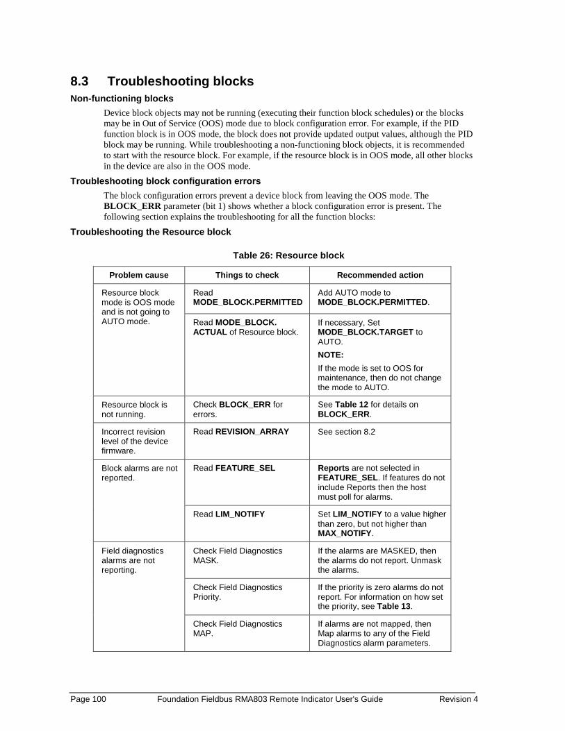
Page 100 Foundation Fieldbus RMA803 Remote Indicator User's Guide Revision 4
8.3 Troubleshooting blocks Non-functioning blocks
Device block objects may not be running (executing their function block schedules) or the blocks may be in Out of Service (OOS) mode due to block configuration error. For example, if the PID function block is in OOS mode, the block does not provide updated output values, although the PID block may be running. While troubleshooting a non-functioning block objects, it is recommended to start with the resource block. For example, if the resource block is in OOS mode, all other blocks in the device are also in the OOS mode.
Troubleshooting block configuration errors The block configuration errors prevent a device block from leaving the OOS mode. The BLOCK_ERR parameter (bit 1) shows whether a block configuration error is present. The following section explains the troubleshooting for all the function blocks:
Troubleshooting the Resource block
Table 26: Resource block
Problem cause Things to check Recommended action
Resource block mode is OOS mode and is not going to AUTO mode.
Read MODE_BLOCK.PERMITTED
Add AUTO mode to MODE_BLOCK.PERMITTED.
Read MODE_BLOCK. ACTUAL of Resource block.
If necessary, Set MODE_BLOCK.TARGET to AUTO. NOTE: If the mode is set to OOS for maintenance, then do not change the mode to AUTO.
Resource block is not running.
Check BLOCK_ERR for errors.
See Table 12 for details on BLOCK_ERR.
Incorrect revision level of the device firmware.
Read REVISION_ARRAY See section 8.2
Block alarms are not reported.
Read FEATURE_SEL Reports are not selected in FEATURE_SEL. If features do not include Reports then the host must poll for alarms.
Read LIM_NOTIFY Set LIM_NOTIFY to a value higher than zero, but not higher than MAX_NOTIFY.
Field diagnostics alarms are not reporting.
Check Field Diagnostics MASK.
If the alarms are MASKED, then the alarms do not report. Unmask the alarms.
Check Field Diagnostics Priority.
If the priority is zero alarms do not report. For information on how set the priority, see Table 13.
Check Field Diagnostics MAP.
If alarms are not mapped, then Map alarms to any of the Field Diagnostics alarm parameters.

Revision 4 Foundation Fieldbus RMA803 Remote Indicator User's Guide Page 101
Troubleshooting the Diagnostics Transducer block
Table 27: Diagnostics Transducer block
Problem cause Things to check Recommended action
Diagnostic Transducer block mode is in OOS and does not change to AUTO mode.
Read MODE_BLOCK.PERMITTED
Add AUTO mode to MODE_BLOCK.PERMITTED.
Read MODE_BLOCK. ACTUAL of Resource block.
If necessary, Set MODE_BLOCK.TARGET to AUTO. NOTE: If the mode is set to OOS for maintenance then do not change the mode to AUTO.
Block alarms are not reported.
Read FEATURE_SEL Reports are not selected in FEATURE_SEL. If features do not include reports then the host must poll for alarms.
Read LIM_NOTIFY Set LIM_NOTIFY to a value higher than zero, but not higher than MAX_NOTIFY.

Page 102 Foundation Fieldbus RMA803 Remote Indicator User's Guide Revision 4
Troubleshooting the LCD Transducer block
Table 28: LCD Transducer block
Problem Cause Things to check Recommended Action
LCD Transducer block mode is in OOS and does not change to AUTO mode.
Read MODE_BLOCK.PERMITTED
Add AUTO mode to MODE_BLOCK.PERMITTED.
Read MODE_BLOCK. ACTUAL of Resource block.
If necessary, Set MODE_BLOCK.TARGET to AUTO. NOTE If the mode is set to OOS for maintenance, then do not change the mode to AUTO.
Writing to display parameters fails.
Check for local display. Advanced Display is required for LCD_TB to work.
If display is available, remove and reconnect the local display, and check if display powers up.
If display is not powering up contact Honeywell TAC. NOTE If a user goes to menus/sub menus in the display, the parameter change will fail. He must navigate out of the menus.
Writing to some of display parameter in SCREEN_1, SCREEN_2, SCREEN_3, SCREEN_4, SCREEN_5, SCREEN_6, SCREEN_7, and SCREEN_8 fails.
Check DISPLAY_TYPE. If there is No Display, then writing to the parameters fails. Parameters write is supported if Advanced display is connected.
Local display shows Attention as title with some text.
Check the DISPLAY_MESSAGE parameters.
Remote Indicator messaging is activated; to clear the message executed the Clear Message method. For more information see section 5.5
Block alarms are not reported.
Read FEATURE_SEL. Reports are not selected in FEATURE_SEL. If features do not include Reports then the host must poll for alarms.
Read LIM_NOTIFY Set LIM_NOTIFY to a value higher than zero, but not higher than MAX_NOTIFY.

Revision 4 Foundation Fieldbus RMA803 Remote Indicator User's Guide Page 103
Troubleshooting the Proportional Integral Derivative (PID) block
Table 29: PID block
Problem Cause Things to check Recommended action
PID block mode is in OOS mode, and does not change to AUTO, CAS, RCAS and ROUT mode.
Read MODE_BLOCK.PERMITTED.
Add AUTO, CAS, RCAS and ROUT modes to MODE_BLOCK.PERMITTED.
Read MODE_BLOCK. ACTUAL of Resource block.
If necessary, Set MODE_BLOCK.TARGET to AUTO. NOTE: If the mode is set to OOS for maintenance then do not change the mode to AUTO.
Check the License Status parameter value of the block
Check whether License for additional function blocks has been purchased. Otherwise purchase the license and then upgrade.
Schedule Block is not scheduled and therefore cannot execute to go to Target Mode. Schedule the block to execute.
PID block mode is in OOS mode with Block configuration Error.
Read parameters: BYPASS SHED_OP
The default values of these parameters are configuration errors and they must be set to a valid range. See Table 34.
Read SP_HI_LIM, SP_LO_LIM OUT_HI_LIM, OUT_LO_LIM
Check that SP_HI_LIM < SP_LO_LIM, OUT_HI_LIM < OUT_LO_LIM.
PID block is not running.
Read the first element of BLOCK_TEST. Number must be increasing indicating that block is running.
If the second element of BLOCK_TEST is nonzero, write all zeroes to element.
If block is not running, check the second element of BLOCK_TEST.
Mode does not change from IM, target mode is MAN, AUTO, or Cas.
No path to process. Assure that the downstream blocks to at least one AO are all in Cas mode and that the path ends in an AO block. All BKCAL connections must be linked.
Mode does not change from MAN; target mode is MAN, AUTO, or Cas.
Check Input blocks. The status of IN is Bad, not connected.
Mode does not go to Cas, target mode is Cas.
Check Upstream block. The upstream block cannot not able to complete cascade initialization for some reason. Assure that BKCAL_OUT is connected to BKCAL_IN of the upstream block.
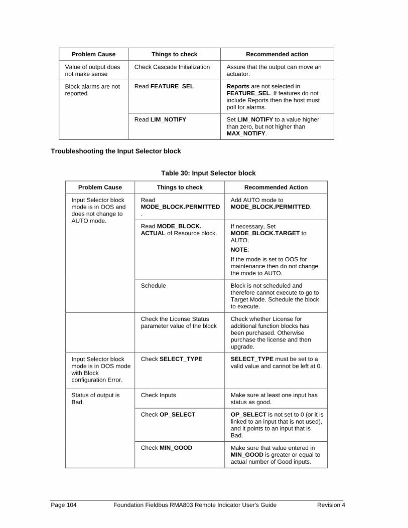
Page 104 Foundation Fieldbus RMA803 Remote Indicator User's Guide Revision 4
Problem Cause Things to check Recommended action
Value of output does not make sense
Check Cascade Initialization Assure that the output can move an actuator.
Block alarms are not reported
Read FEATURE_SEL Reports are not selected in FEATURE_SEL. If features do not include Reports then the host must poll for alarms.
Read LIM_NOTIFY Set LIM_NOTIFY to a value higher than zero, but not higher than MAX_NOTIFY.
Troubleshooting the Input Selector block
Table 30: Input Selector block
Problem Cause Things to check Recommended Action
Input Selector block mode is in OOS and does not change to AUTO mode.
Read MODE_BLOCK.PERMITTED.
Add AUTO mode to MODE_BLOCK.PERMITTED.
Read MODE_BLOCK. ACTUAL of Resource block.
If necessary, Set MODE_BLOCK.TARGET to AUTO. NOTE: If the mode is set to OOS for maintenance then do not change the mode to AUTO.
Schedule Block is not scheduled and therefore cannot execute to go to Target Mode. Schedule the block to execute.
Check the License Status parameter value of the block
Check whether License for additional function blocks has been purchased. Otherwise purchase the license and then upgrade.
Input Selector block mode is in OOS mode with Block configuration Error.
Check SELECT_TYPE SELECT_TYPE must be set to a valid value and cannot be left at 0.
Status of output is Bad.
Check Inputs Make sure at least one input has status as good.
Check OP_SELECT OP_SELECT is not set to 0 (or it is linked to an input that is not used), and it points to an input that is Bad.
Check MIN_GOOD Make sure that value entered in MIN_GOOD is greater or equal to actual number of Good inputs.

Revision 4 Foundation Fieldbus RMA803 Remote Indicator User's Guide Page 105
Problem Cause Things to check Recommended Action
Block alarms are not reported.
Read FEATURE_SEL. Reports are not selected in FEATURE_SEL. If features do not include Reports then the host must poll for alarms.
Read LIM_NOTIFY. Set LIM_NOTIFY to a value higher than zero, but not higher than MAX_NOTIFY.

Page 106 Foundation Fieldbus RMA803 Remote Indicator User's Guide Revision 4
Troubleshooting the Integrator block
Table 31: Integrator block
Problem Cause Things to check Recommended Action
Integrator block mode is in OOS and does not change to AUTO mode.
Read MODE_BLOCK.PERMITTED.
Add AUTO mode to MODE_BLOCK.PERMITTED.
Read MODE_BLOCK.ACTUAL of Resource block.
If necessary, set MODE_BLOCK.TARGET to AUTO. NOTE: If the mode is to OOS for maintenance, then do not change the mode to AUTO.
Schedule Block is not scheduled and therefore cannot execute to go to Target Mode. Schedule the block to execute.
Check the License Status parameter value of the block
Check whether License for additional function blocks has been purchased. Otherwise purchase the license and then upgrade.
Integrator block mode is in OOS mode with Block Configuration Error.
Check INTEG_TYPE INTEG_TYPE must not be zero/blank.
Check TIME_UNIT 1 and TIME_UNIT 2.
TIME_UNIT1 & TIME_UNIT 2 must not be zero/blank.
Value of output does not make sense.
Check TOTAL_SP. TOTAL_SP must be set to a valid value and cannot be left at 0, if INTEG_TYPE is UP_AUTO, DN_AUTO.
Value of output is going in negative value.
Check REV_FLOW1 and REV_FLOW 2.
For forward flow REV_FLOW1 and REV_FLOW 2 must be set as Forward, and for reverse flow REV_FLOW1 & REV_FLOW 2 must be set as Reverse.
Check INTEG_OPTS Flow forward and flow reverse
For forward flow in INTEG_OPTS flow, forward must be selected and for reverse flow in INTEG_OPTS flow, reverse must be selected.
Block alarms are not reported.
Read FEATURE_SEL. Reports are not selected in FEATURE_SEL. If features do not include Reports, then the host must poll for alarms.
Read LIM_NOTIFY. Set LIM_NOTIFY to a value higher than zero, but not higher than MAX_NOTIFY.

Revision 4 Foundation Fieldbus RMA803 Remote Indicator User's Guide Page 107
Troubleshooting the Arithmetic block
Table 32: Arithmetic block
Problem Cause Things to check Recommended Action
Arithmetic block mode is in OOS and does not change to AUTO mode.
Read MODE_BLOCK.PERMITTED
Add AUTO mode to MODE_BLOCK.PERMITTED.
Read MODE_BLOCK. ACTUAL of Resource block.
If necessary, set MODE_BLOCK.TARGET to AUTO. NOTE: If the mode is set to OOS for maintenance, then do not change the mode to AUTO.
Mode does not change from OOS.
Configuration error. BLOCK_ERR shows the Block Configuration Error condition, since ARITH_TYPE is not set.
Value of output is incorrect
Error in configuration. Ensure that engineering units are correct for the computation. If that fails, see section 3.
Block alarms are not reported.
Read FEATURE_SEL. Reports are not selected in FEATURE_SEL. If features do not include reports then the host must poll for alarms.
Read LIM_NOTIFY. Set LIM_NOTIFY to a value higher than zero, but not higher than MAX_NOTIFY.
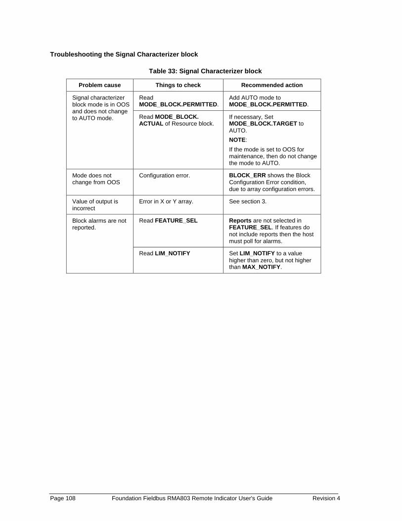
Page 108 Foundation Fieldbus RMA803 Remote Indicator User's Guide Revision 4
Troubleshooting the Signal Characterizer block
Table 33: Signal Characterizer block
Problem cause Things to check Recommended action
Signal characterizer block mode is in OOS and does not change to AUTO mode.
Read MODE_BLOCK.PERMITTED.
Add AUTO mode to MODE_BLOCK.PERMITTED.
Read MODE_BLOCK. ACTUAL of Resource block.
If necessary, Set MODE_BLOCK.TARGET to AUTO. NOTE: If the mode is set to OOS for maintenance, then do not change the mode to AUTO.
Mode does not change from OOS
Configuration error. BLOCK_ERR shows the Block Configuration Error condition, due to array configuration errors.
Value of output is incorrect
Error in X or Y array. See section 3.
Block alarms are not reported.
Read FEATURE_SEL Reports are not selected in FEATURE_SEL. If features do not include reports then the host must poll for alarms.
Read LIM_NOTIFY Set LIM_NOTIFY to a value higher than zero, but not higher than MAX_NOTIFY.
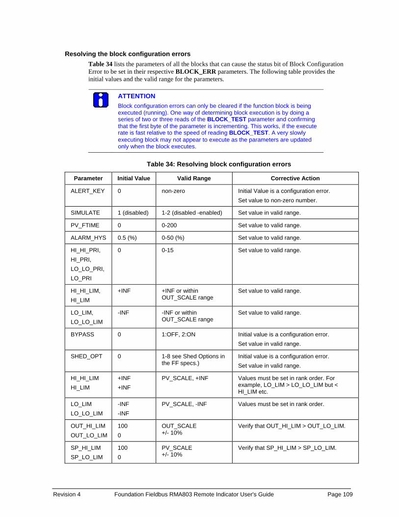
Revision 4 Foundation Fieldbus RMA803 Remote Indicator User's Guide Page 109
Resolving the block configuration errors Table 34 lists the parameters of all the blocks that can cause the status bit of Block Configuration Error to be set in their respective BLOCK_ERR parameters. The following table provides the initial values and the valid range for the parameters.
ATTENTION Block configuration errors can only be cleared if the function block is being executed (running). One way of determining block execution is by doing a series of two or three reads of the BLOCK_TEST parameter and confirming that the first byte of the parameter is incrementing. This works, if the execute rate is fast relative to the speed of reading BLOCK_TEST. A very slowly executing block may not appear to execute as the parameters are updated only when the block executes.
Table 34: Resolving block configuration errors
Parameter Initial Value Valid Range Corrective Action
ALERT_KEY 0 non-zero Initial Value is a configuration error. Set value to non-zero number.
SIMULATE 1 (disabled) 1-2 (disabled -enabled) Set value in valid range.
PV_FTIME 0 0-200 Set value to valid range.
ALARM_HYS 0.5 (%) 0-50 (%) Set value to valid range.
HI_HI_PRI, HI_PRI, LO_LO_PRI, LO_PRI
0 0-15 Set value to valid range.
HI_HI_LIM, HI_LIM
+INF +INF or within OUT_SCALE range
Set value to valid range.
LO_LIM, LO_LO_LIM
-INF -INF or within OUT_SCALE range
Set value to valid range.
BYPASS 0 1:OFF, 2:ON Initial value is a configuration error. Set value in valid range.
SHED_OPT 0 1-8 see Shed Options in the FF specs.)
Initial value is a configuration error. Set value in valid range.
HI_HI_LIM HI_LIM
+INF +INF
PV_SCALE, +INF Values must be set in rank order. For example, LO_LIM > LO_LO_LIM but < HI_LIM etc.
LO_LIM LO_LO_LIM
-INF -INF
PV_SCALE, -INF Values must be set in rank order.
OUT_HI_LIM OUT_LO_LIM
100 0
OUT_SCALE +/- 10%
Verify that OUT_HI_LIM > OUT_LO_LIM.
SP_HI_LIM SP_LO_LIM
100 0
PV_SCALE +/- 10%
Verify that SP_HI_LIM > SP_LO_LIM.
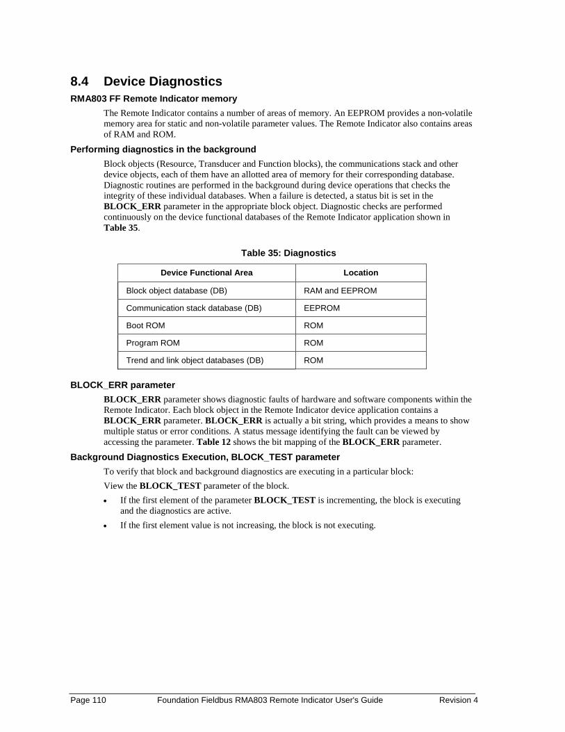
Page 110 Foundation Fieldbus RMA803 Remote Indicator User's Guide Revision 4
8.4 Device Diagnostics RMA803 FF Remote Indicator memory
The Remote Indicator contains a number of areas of memory. An EEPROM provides a non-volatile memory area for static and non-volatile parameter values. The Remote Indicator also contains areas of RAM and ROM.
Performing diagnostics in the background Block objects (Resource, Transducer and Function blocks), the communications stack and other device objects, each of them have an allotted area of memory for their corresponding database. Diagnostic routines are performed in the background during device operations that checks the integrity of these individual databases. When a failure is detected, a status bit is set in the BLOCK_ERR parameter in the appropriate block object. Diagnostic checks are performed continuously on the device functional databases of the Remote Indicator application shown in Table 35.
Table 35: Diagnostics
Device Functional Area Location
Block object database (DB) RAM and EEPROM
Communication stack database (DB) EEPROM
Boot ROM ROM
Program ROM ROM
Trend and link object databases (DB) ROM BLOCK_ERR parameter
BLOCK_ERR parameter shows diagnostic faults of hardware and software components within the Remote Indicator. Each block object in the Remote Indicator device application contains a BLOCK_ERR parameter. BLOCK_ERR is actually a bit string, which provides a means to show multiple status or error conditions. A status message identifying the fault can be viewed by accessing the parameter. Table 12 shows the bit mapping of the BLOCK_ERR parameter.
Background Diagnostics Execution, BLOCK_TEST parameter To verify that block and background diagnostics are executing in a particular block: View the BLOCK_TEST parameter of the block. • If the first element of the parameter BLOCK_TEST is incrementing, the block is executing
and the diagnostics are active. • If the first element value is not increasing, the block is not executing.
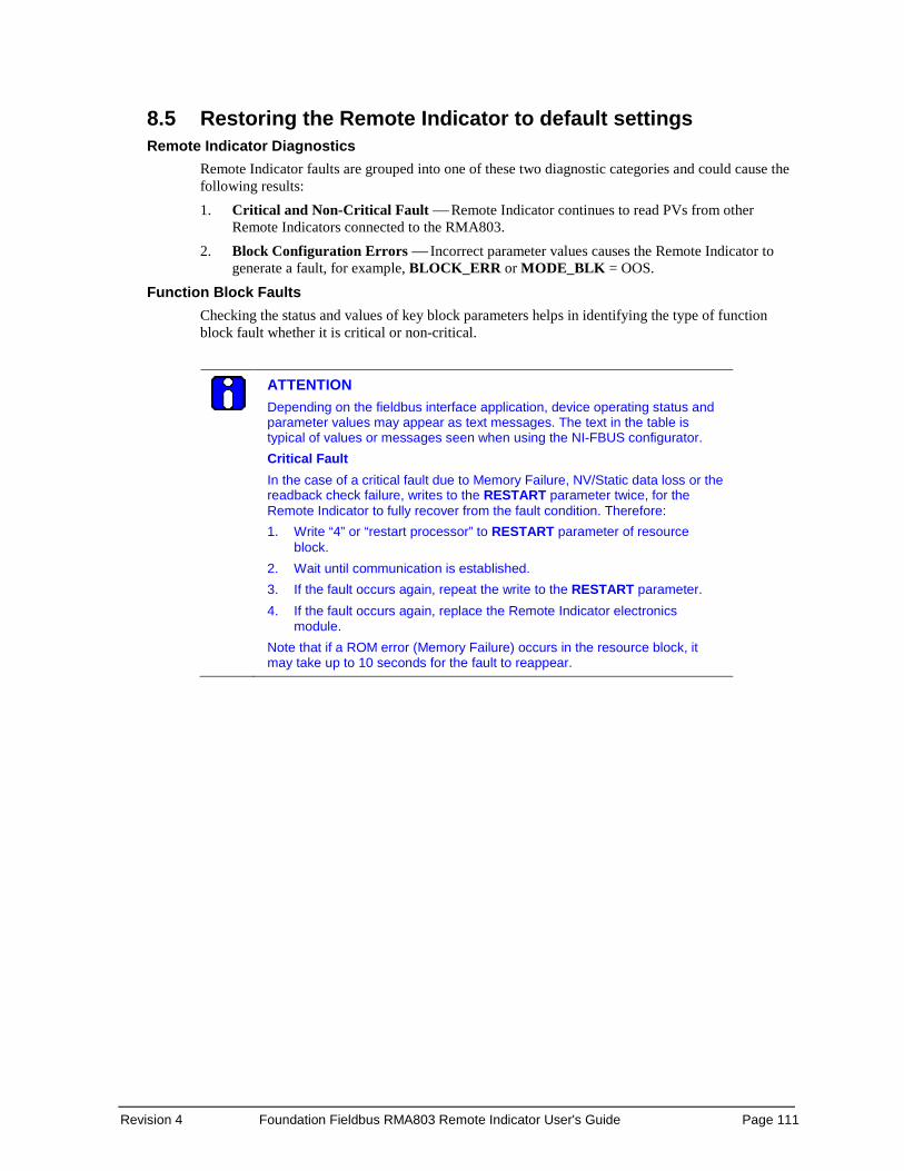
Revision 4 Foundation Fieldbus RMA803 Remote Indicator User's Guide Page 111
8.5 Restoring the Remote Indicator to default settings Remote Indicator Diagnostics
Remote Indicator faults are grouped into one of these two diagnostic categories and could cause the following results: 1. Critical and Non-Critical Fault Remote Indicator continues to read PVs from other
Remote Indicators connected to the RMA803. 2. Block Configuration Errors Incorrect parameter values causes the Remote Indicator to
generate a fault, for example, BLOCK_ERR or MODE_BLK = OOS. Function Block Faults
Checking the status and values of key block parameters helps in identifying the type of function block fault whether it is critical or non-critical.
ATTENTION Depending on the fieldbus interface application, device operating status and parameter values may appear as text messages. The text in the table is typical of values or messages seen when using the NI-FBUS configurator. Critical Fault In the case of a critical fault due to Memory Failure, NV/Static data loss or the readback check failure, writes to the RESTART parameter twice, for the Remote Indicator to fully recover from the fault condition. Therefore: 1. Write “4” or “restart processor” to RESTART parameter of resource
block. 2. Wait until communication is established. 3. If the fault occurs again, repeat the write to the RESTART parameter. 4. If the fault occurs again, replace the Remote Indicator electronics
module. Note that if a ROM error (Memory Failure) occurs in the resource block, it may take up to 10 seconds for the fault to reappear.
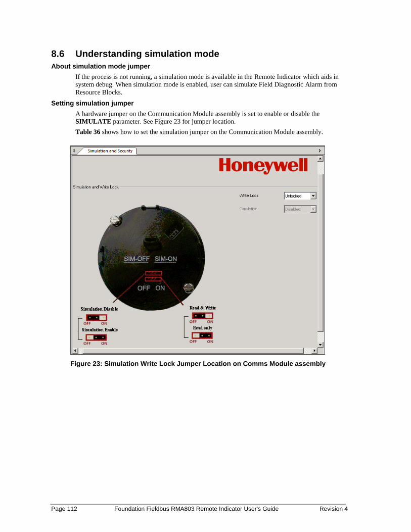
Page 112 Foundation Fieldbus RMA803 Remote Indicator User's Guide Revision 4
8.6 Understanding simulation mode About simulation mode jumper
If the process is not running, a simulation mode is available in the Remote Indicator which aids in system debug. When simulation mode is enabled, user can simulate Field Diagnostic Alarm from Resource Blocks.
Setting simulation jumper A hardware jumper on the Communication Module assembly is set to enable or disable the SIMULATE parameter. See Figure 23 for jumper location. Table 36 shows how to set the simulation jumper on the Communication Module assembly.
Figure 23: Simulation Write Lock Jumper Location on Comms Module assembly

Revision 4 Foundation Fieldbus RMA803 Remote Indicator User's Guide Page 113
Table 36: Setting the Simulation Jumper
To Set the Jumper to:
Disable the SIMULATE parameter. (Set Remote Indicator for normal operation.)
“OFF” position on the Transducer board.
Enable the SIMULATE parameter. (For testing or debugging purposes.)
“ON” position on the Transducer board.
Enabling simulation mode
The SIMULATE parameter is enabled by setting the hardware simulation jumper to the “ON” position.
Simulation mode truth table Table 37 shows the states of the simulation jumper and SIMULATE parameter shows how to activate the simulation mode.
Table 37: Simulation Mode Truth Table
When the Simulation Jumper
(HW_SIMULATE_JUMPER_STATE) on Transducer
board is set to:
and the SIMULATE Enable_Disable is set to:
(Disabled) (Active)
“OFF” Position Simulation Disabled Simulation Disabled
“ON” Position Simulation Disabled Simulation Active
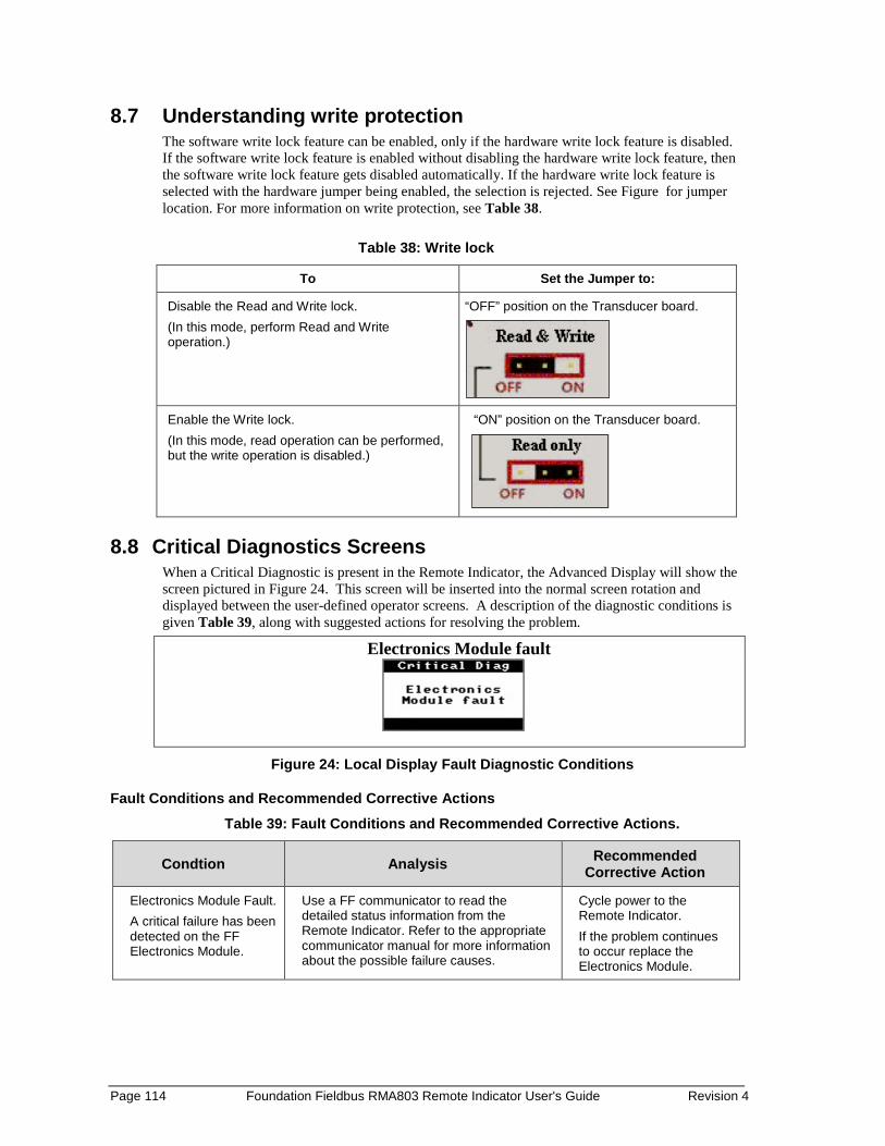
Page 114 Foundation Fieldbus RMA803 Remote Indicator User's Guide Revision 4
8.7 Understanding write protection The software write lock feature can be enabled, only if the hardware write lock feature is disabled. If the software write lock feature is enabled without disabling the hardware write lock feature, then the software write lock feature gets disabled automatically. If the hardware write lock feature is selected with the hardware jumper being enabled, the selection is rejected. See Figure for jumper location. For more information on write protection, see Table 38.
Table 38: Write lock
To Set the Jumper to:
Disable the Read and Write lock. (In this mode, perform Read and Write operation.)
“OFF” position on the Transducer board.
Enable the Write lock. (In this mode, read operation can be performed, but the write operation is disabled.)
“ON” position on the Transducer board.
8.8 Critical Diagnostics Screens When a Critical Diagnostic is present in the Remote Indicator, the Advanced Display will show the screen pictured in Figure 24. This screen will be inserted into the normal screen rotation and displayed between the user-defined operator screens. A description of the diagnostic conditions is given Table 39, along with suggested actions for resolving the problem.
Electronics Module fault
Figure 24: Local Display Fault Diagnostic Conditions
Fault Conditions and Recommended Corrective Actions Table 39: Fault Conditions and Recommended Corrective Actions.
Condtion Analysis Recommended Corrective Action
Electronics Module Fault. A critical failure has been detected on the FF Electronics Module.
Use a FF communicator to read the detailed status information from the Remote Indicator. Refer to the appropriate communicator manual for more information about the possible failure causes.
Cycle power to the Remote Indicator. If the problem continues to occur replace the Electronics Module.

Revision 4 Foundation Fieldbus RMA803 Remote Indicator User's Guide Page 115
9. Parts List 9.1 Overview
Individually saleable parts for the various Remote IndicatorRemote Indicator models are listed in this section. Some parts are illustrated for identification. Parts are identified and listed in the corresponding tables as follows:
• Individually saleable parts are indicated in each figure by key number callout. Table 40 is a summarized list of recommended spare parts.
Table 40: Summary List of Recommended Spare Parts
Part Number Description Figure No.
Electronics Housing Assembly
50086423-505 50086423-506
FieldBus Electronics Module Without REED Sensor PWA FIeldBus Electronics Module With REED Sensor PWA
Figure 26 5 1 1-2 2-4
50075472-533 50075472-534
FieldBus Terminal Block Assy Without Lightning Protection FieldBus Terminal Block Assy With Lightning Protection
Figure 27 3 1 1 1-2
Figure 25: Pipe and Wall Bracket Parts
Table 41: Pipe and Wall Bracket Parts (Refer to Figure 25)
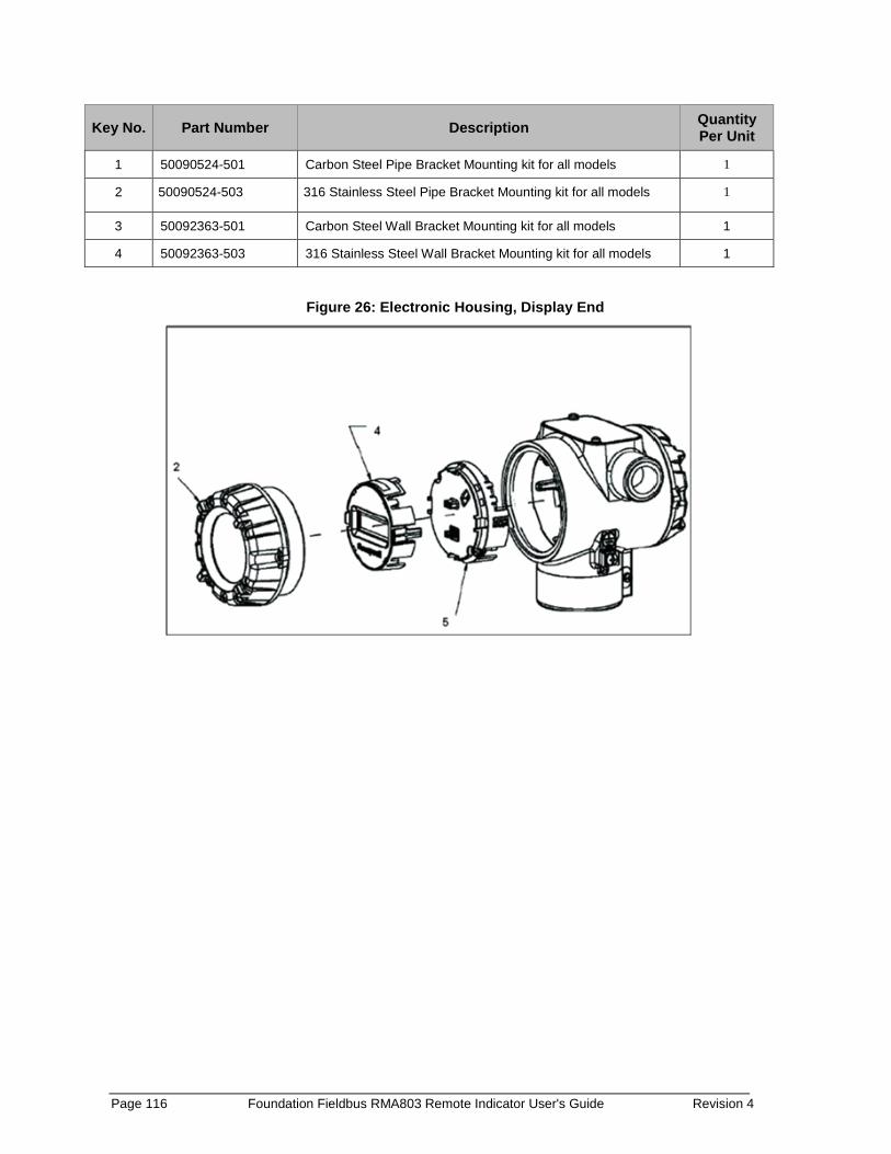
Page 116 Foundation Fieldbus RMA803 Remote Indicator User's Guide Revision 4
Key No. Part Number Description Quantity Per Unit
1 50090524-501 Carbon Steel Pipe Bracket Mounting kit for all models 1
2 50090524-503 316 Stainless Steel Pipe Bracket Mounting kit for all models 1
3 50092363-501 Carbon Steel Wall Bracket Mounting kit for all models 1
4 50092363-503 316 Stainless Steel Wall Bracket Mounting kit for all models 1
Figure 26: Electronic Housing, Display End
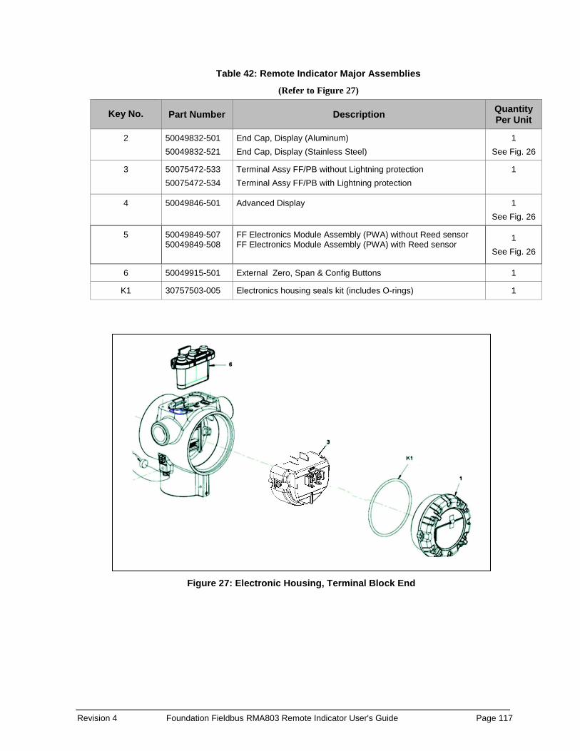
Revision 4 Foundation Fieldbus RMA803 Remote Indicator User's Guide Page 117
Table 42: Remote Indicator Major Assemblies
(Refer to Figure 27)
Key No. Part Number Description Quantity Per Unit
2 50049832-501 50049832-521
End Cap, Display (Aluminum) End Cap, Display (Stainless Steel)
1 See Fig. 26
3 50075472-533 50075472-534
Terminal Assy FF/PB without Lightning protection Terminal Assy FF/PB with Lightning protection
1
4 50049846-501 Advanced Display 1 See Fig. 26
5 50049849-507 50049849-508
FF Electronics Module Assembly (PWA) without Reed sensor FF Electronics Module Assembly (PWA) with Reed sensor
1 See Fig. 26
6 50049915-501 External Zero, Span & Config Buttons 1
K1 30757503-005 Electronics housing seals kit (includes O-rings) 1
Figure 27: Electronic Housing, Terminal Block End

Page 118 Foundation Fieldbus RMA803 Remote Indicator User's Guide Revision 4
Appendix A. Product Certifications
A1. European Directive Information (CE Mark) RMA800 SmartLine Remote Indicator Series EU Declaration of conformity (Document #32302406), can be downloaded here: EU Declaration

Revision 4 Foundation Fieldbus RMA803 Remote Indicator User's Guide Page 119
Hazardous Locations Certifications
MSG CODE
AGENCY TYPE OF PROTECTION Electrical Parameters
Ambient Temperature
A FM Approvals TM (USA)
Explosion proof: Class I, Division 1, Groups A, B, C, D; T6..T4 Dust Ignition Proof: Class II, III, Division 1, Groups E, F, G; T4 Class 1, Zone 1, AEx d IIC T4 Gb Class 2, Zone 21, AEx tb IIIC T 95oC IP 66 Db
Note 1 T6: -50ºC to +65ºC T4, T5: -50 ºC to 85ºC
Intrinsically Safe: Class I, II, III, Division 1, Groups A, B, C,D, E, F, G; T4
Class I Zone 0 AEx ia IIC T4 Ga
Note 2 -50 ºC to 70ºC
Non-Incendive Class I, Division 2, Groups A, B, C, D; T4 Class I Zone 2 AEx nA IIC T4 Gc
Note 1 -50 ºC to 85ºC
Enclosure: Type 4X/ IP66/ IP67 ALL ALL
Standards: FM 3600:2018;FM 3611: 2018; ANSI/ UL 60079-0: 2013; ANSI/ UL 60079-1: 2015; FM 3610: 2018; ANSI/ UL 60079-11: 2014; FM 3810: 2018; ANSI/ UL 60079-15: 2013; ANSI/ UL 60079-31 : 2015; FM Class 3615: 2018; FM 3616: 2011
B CSA-Canada
Explosion proof: CSA 14.2689056 Class I, Division 1, Groups A, B, C, D;T6..T4 Dust Ignition Proof: Class II, III, Division 1, Groups E, F, G; T4 Class I Zone 1 Ex db IIC T4 Gb Ex db IIC T4 Gb Zone 21 Ex tb IIIC T 95oC Db Ex tb IIIC T 95oC Db
Note 1 T6: -50ºC to +65ºC T4, T5: -50 ºC to 85ºC
Intrinsically Safe: CSA 14.2689056 Class I, II, III, Division 1, Groups A, B, C, D, E, F, G; T4
Ex ia IIC T4 Ga
Note 2 -50oC to 70oC
Non-Incendive CSA 14.2689056 Class I, Division 2, Groups A, B, C, D; T4
Class I Zone 2 Ex nA IIC T4 Gc Ex nA IIC T4 Gc
Note 1 -50oC to 85oC
Enclosure: Type 4X/ IP66/ IP67 ALL ALL

Page 120 Foundation Fieldbus RMA803 Remote Indicator User's Guide Revision 4
C ATEX
Flame-proof: II 2 G Ex d IIC T4 Gb II 2 D Ex tb IIIC T 95oC Db
Note 1 -20 ºC to 70ºC
Intrinsically Safe: II 2 G Ex ia IIC T4 Ga FISCO Field Device
Ex ia IIC T4
Note 2 -50oC to 70oC
Non-Incendive II 3 G Ex nA IIC T4 Gc Note 1 -50oC to 70oC
Enclosure: Type 4X/ IP66/ IP67 ALL ALL STANDARDS: EN 60079-0: 2012; EN 60079-1 : 2007; EN 60079-11 : 2011; EN 60079-26 : 2006; EN 60079-31: 2009; EN 60079-15 : 2010; IEC 60529 : 2009 with Corr 3
D IECEx
Flame-proof: Ex d IIC T4 Gb Ex tb IIIC T 95oC IP 66 Db
Note 1 -20 ºC to 70ºC
Intrinsically Safe: Ex ia IIC T4 Ga FISCO Field Device Ex ia IIC T4
Note 2 -50oC to 70oC
Non-Incendive Ex nA IIC T4 Gc Note 1 -50oC to 70oC
Enclosure: Type 4X/ IP66/ IP67 ALL ALL STANDARDS: IEC 60079-0: 2011, Edition 6; IEC 60079-1 : 2007-04, Edition 6; IEC 60079-11 : 2011, Edition 6; IEC 60079-15 : 2010, Edition 4 IEC 60079-26 : 2006, Edition 2; IEC 60079-31 : 2008, Edition 1, IEC 60529 : 2009 with Corr 3
E SAEx
Flame-proof: Ex db IIC T6..T5 Gb Ex tb IIIC T 95oC Db
Note 1 T6: -20oC to 65oC T95oC, T5: -20oC to 85oC
Intrinsically Safe: Ex ia IIC T4 Ga Ex ic IIC T4 Gc
Note 2 -20oC to 70oC
Non-Incendive Ex ec IIC T4 Gc Note 1 --20oC to 85oC
Enclosure: IP66/ IP67 ALL ALL STANDARDS: IEC 60079-0: 2011; IEC 60079-1: 2014; IEC 60079-11: 2011; IEC 60079-7: 2006; IEC 60079-31: 2013
P CCoE/ PESO
Flame-proof: Ex db IIC T6..T5 Gb Note 1 T6: -20oC to 65oC
T5: -20oC to 85oC Intrinsically Safe: Ex ia IIC T4 Ga Note 2 -20oC to 70oC
Enclosure: IP66/ IP67 ALL ALL STANDARDS: IEC 60079-0: 2011; IEC 60079-1: 2014; IEC 60079-11: 2011; IEC 60079-7: 2006; IEC 60079-31: 2013
Notes 1. Operating Parameters: Voltage= 12 to 42 V Current= 25 mA 2. Intrinsically Safe Entity Parameters For details see Control Drawing, 50089981.

Revision 4 Foundation Fieldbus RMA803 Remote Indicator User's Guide Page 121
Marking ATEX Directive a. General
The following information is provided as part of the labeling of the Remote Indicator:
Name and Address of the manufacturer
The serial number of the Remote Indicator is located on the Meter Body data-plate. The first two digits of the serial number identify the year (02) and the second two digits identify the week of the year (23); for example, 0223xxxxxxxx indicates that the product was manufactured in 2002, in the 23rd week.
b. Apparatus Marked with Multiple Types of Protection The user must determine the type of protection required for installation the equipment. The user shall then check the box [ ] adjacent to the type of protection used on the equipment certification nameplate. Once a type of protection has been checked on the nameplate, the equipment shall not then be reinstalled using any of the other certification types.
c. WARNINGS and Cautions Non-Incendive / Non-Sparking (Division 2 and Zone 2 Environments):
WARNING – EXPLOSION HAZARD – SUBSTITUTION OF COMPONENTS MAY IMPAIR SUITABILITY FOR CLASS I, DIVISION 2
Intrinsically Safe (Divisions 1, Zone 1 and Zone 2 Environments):
WARNING – EXPLOSION HAZARD – SUBSTITUTION OF COMPONENTS MAY IMPAIR INTRINSIC SAFETY.
WARNING – DO NOT OPEN WHEN AN EXPLOSIVE GAS ATMOSPHERE IS PRESENT.
Explosion-Proof (Division 1 and Zone 1 Environments):
WARNING – DO NOT OPEN WHEN AN EXPLOSIVE GAS ATMOSPHERE IS PRESENT.
WARNING – DO NOT OPEN WHEN ENERGIZED “OPEN CIRCUIT BEFORE REMOVING COVER”
Flameproof (Division 1 and Zone 1 Environments):
WARNING – DO NOT OPEN WHEN ENERGIZED
General Requirements / Increased Safety (Zone 1):
WARNING – DO NOT OPEN WHEN ENERGIZED
WARNING – OPEN CIRCUIT BEFORE REMOVING COVER
All Protective Measures:
WARNING: FOR CONNECTION IN AMBIENTS ABOVE 60oC USE WIRE RATED 105oC
Page 122 Foundation Fieldbus RMA803 Remote Indicator User's Guide Revision 4
Conditions of Use “for Ex Equipment”, Hazardous Location Equipment or “Schedule of Limitations”
a. Consult the manufacturer for dimensional information on the flameproof joints for repair.
b. Painted surface of the RMA 800 series may store electrostatic charge and become a source of ignition in applications with a low relative humidity less than approximately30% relative humidity where the painted surface is relatively free of surface contamination such as dirt, dust or oil. Cleaning of the painted surface should only be done with a damp cloth.
c. The ambient temperature range, maximum process temperature and applicable temperature class of the equipment is as follows:
RMA801: T4 for -50˚C < Ta < 85˚C
RMA803: T4 for -20˚C < Ta < 70˚C
d. The RMA800 series enclosure contains aluminum and is considered to present a potential risk of ignition by impact or friction. Care must be considered during installation and use to prevent impact or friction to avoid impact.
e. If a charge-generating mechanism is present, the exposed metallic part on the enclosure is capable of storing a level of electrostatic charge that could become incendive for IIC gases. Therefore, the user/installer shall implement precautions to prevent the buildup of electrostatic charge, e.g. earthing the metallic part. This is particularly important if the equipment is installed in a zone 0 location.
f. On installation, the RMA800 series shall be provided with supply transient protection external to the apparatus such that the voltage at the supply terminals of the RMA800 series does not exceed 140% of the voltage rating of the equipment.

Revision 4 Foundation Fieldbus RMA803 Remote Indicator User's Guide Page 123
Control Drawing: 50089981
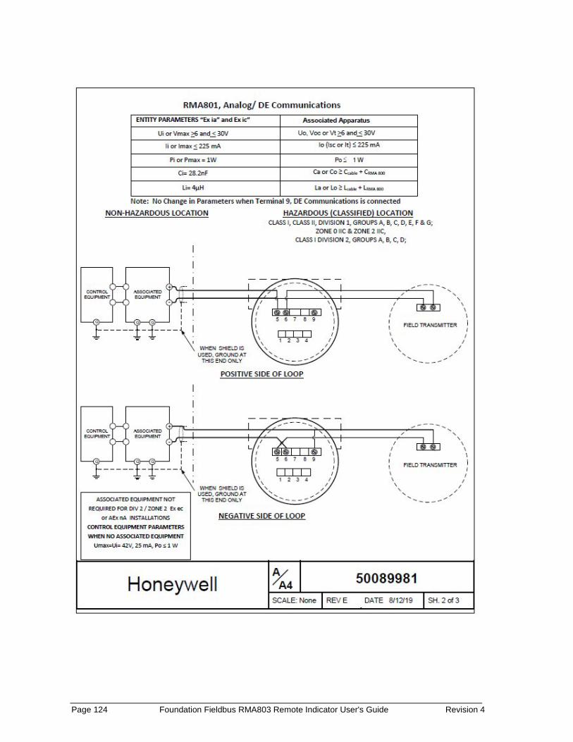
Page 124 Foundation Fieldbus RMA803 Remote Indicator User's Guide Revision 4
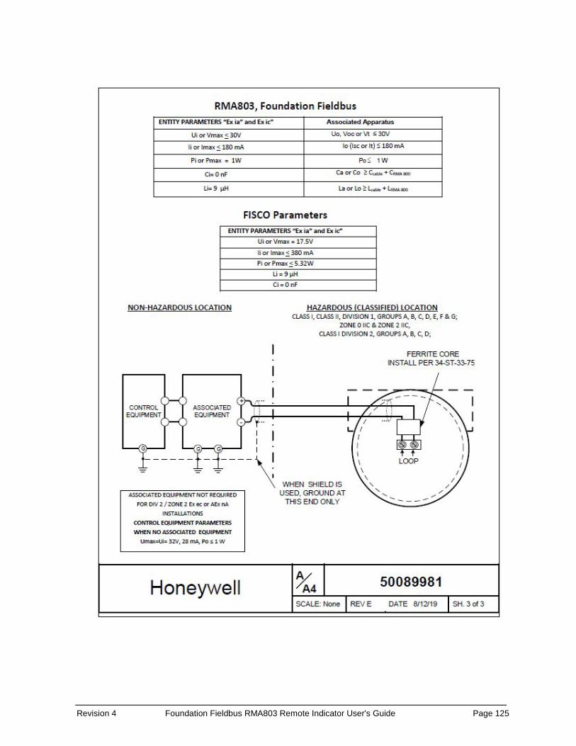
Revision 4 Foundation Fieldbus RMA803 Remote Indicator User's Guide Page 125
Page 126 Foundation Fieldbus RMA803 Remote Indicator User's Guide Revision 4
10. INDEX
A Advanced Display Menus ........................................... 18
Diagnostics Menu .................................................. 18 Display Setup Menus ............................................. 19 Information Menus ................................................ 22
Arithmetic block ........................................................ 78
C Certifications and Approvals
Conditions of Use ........................................... 122 Marking ATEX Directive ................................ 121
Changing the Default Failsafe Direction Failsafe Operation ................................................. 22
communication with host systems .............................. 9 Configuration ............................................................. 28 Configuring the function block ................................... 32 Configuring using Field Device Manager (FDM) ......... 89 Control Drawing ....................................................... 123 Copyrights, Notices and Trademarks ................ ii
D Default settings ........................................................ 111 Device Diagnostics ................................................... 110 Diagnostic Transducer block ...................................... 45 Diagnostics Menu....................................................... 18 Display Options ............................................................ 6 Display Setup Menus.................................................. 21 Downloading the firmware ........................................ 94
E Editing a Numeric Value ............................................. 17
F Features and Options ................................................... 3
G Getting started ............................................................. 7
I Importing (DD) files .................................................... 28 Input Selector block ................................................... 64 Installation and Startup ............................................. 11 Integrator block ......................................................... 69
L LCD Transducer block ................................................ 48 Licensing for Function Blocks .................................... 96
M Maintenance ............................................................. 92
Preventive Maintenance Practices and Schedules 92 Replacing the Communication Module ................. 92
MAO Block ................................................................. 87 Monitoring the Basic and Advanced Displays
Advanced Displays ................................................ 25 Mounting Remote Indicator ...................................... 11
O Operation .................................................................. 15
Three-Button Operation ....................................... 15 Optional 3-Button Assembly ....................................... 6
P Parts List .................................................................. 115 Patent Notice .......................................................... iv Performing block instantiation .................................. 91 PID block with auto tune ........................................... 54 Product Certifications .............................................. 118 Proportional Integral Derivative (PID) ....................... 54
R Resource block .......................................................... 35 RMA803 major assembly ............................................. 4 RMA803 Remote Indicator .......................................... 1
S Safety Certification Information .................................. 6 Signal Characterizer block ......................................... 83 Simulation mode ..................................................... 112 Support and Contact Information .............................. iv Symbol Definitions ...................................................... v
T Terms and Acronyms .................................................. vii Three-Button Operation ............................................ 15
Advanced Display Entries ...................................... 18 Data Entry ............................................................. 16 Menu Navigation................................................... 16
Troubleshooting ........................................................ 97 Critical Diagnostics Screens ................................. 114

Revision 4 Foundation Fieldbus RMA803 Remote Indicator User's Guide Page 127
V Verifying communication ............................................. 8 Verifying the installation .............................................. 7
W Wiring a Remote Indicator ........................................ 13 Write protection ..................................................... 114

For more information To learn more about SmartLine Transmitters, visit www.honeywellprocess.com Or contact your Honeywell Account Manager
Process Solutions Honeywell
1250 W Sam Houston Pkwy S Houston, TX 77042
Honeywell Control Systems Ltd Honeywell House, Skimped Hill Lane Bracknell, England, RG12 1EB
34-ST-25-51, Rev.4 March 2020 2020 Honeywell International Inc.
Shanghai City Centre, 100 Jungi Road Shanghai, China 20061 www.honeywellprocess.com
Sales and Service For application assistance, current specifications, pricing, or name of the nearest Authorized Distributor, contact one of the offices below.
ASIA PACIFIC Honeywell Process Solutions, (TAC) [email protected] Australia Honeywell Limited Phone: +(61) 7-3846 1255 FAX: +(61) 7-3840 6481 Toll Free 1300-36-39-36 Toll Free Fax: 1300-36-04-70 China – PRC - Shanghai Honeywell China Inc. Phone: (86-21) 5257-4568 Fax: (86-21) 6237-2826 Singapore Honeywell Pte Ltd. Phone: +(65) 6580 3278 Fax: +(65) 6445-3033 South Korea Honeywell Korea Co Ltd Phone: +(822) 799 6114 Fax: +(822) 792 9015
EMEA Honeywell Process Solutions, Phone: + 80012026455 or +44 (0)1344 656000 Email: (Sales) [email protected] or (TAC) [email protected]
AMERICAS Honeywell Process Solutions, Phone: (TAC) 1-800-423-9883 or 215/641-3610 (Sales) 1-800-343-0228 Email: (Sales) [email protected] or (TAC) [email protected]