
FOUNDATION Fieldbus 4 - WordPress.com
44
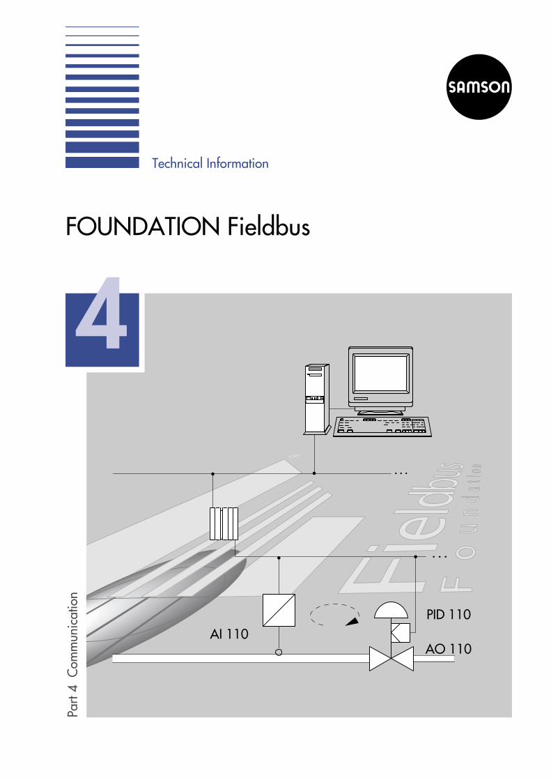
Part 4 Communication FOUNDATION Fieldbus Technical Information 4 AI 110 AO 110 PID 110
Transcript of FOUNDATION Fieldbus 4 - WordPress.com
Part
4C
omm
unic
atio
n
FOUNDATION Fieldbus
Technical Information
4
AI 110AO 110
PID 110
Part 1: Fundamentals
Part 2: Self-operated Regulators
Part 3: Control Valves
Part 4: Communication
Part 5: Building Automation
Part 6: Process Automation
Should you have any further questions or suggestions, please donot hesitate to contact us:
SAMSON AG Phone (+49 69) 4 00 94 67V74 / Schulung Telefax (+49 69) 4 00 97 16Weismüllerstraße 3 E-Mail: [email protected] Frankfurt Internet: http://www.samson.de
Technical Information

Foundation Fieldbus
Introduction . . . . . . . . . . . . . . . . . . . . . . . . . . . . . 5
Historical development . . . . . . . . . . . . . . . . . . . . . . . . . . . . . . . . . 6
User organization . . . . . . . . . . . . . . . . . . . . . . . . . . . . . . . . . . . . . 7
Approval of devices. . . . . . . . . . . . . . . . . . . . . . . . . . . . . . . . . . . . 7
Performance features . . . . . . . . . . . . . . . . . . . . . . . . . 8
Layered communications model . . . . . . . . . . . . . . . . . . . 10
Physical layer . . . . . . . . . . . . . . . . . . . . . . . . . . . . 12
H1 bus . . . . . . . . . . . . . . . . . . . . . . . . . . . . . . . . . . . . . . . . . . . . 13
• EEx-i instruments . . . . . . . . . . . . . . . . . . . . . . . . . . . . . . . . . . . 15
High Speed Ethernet (HSE) . . . . . . . . . . . . . . . . . . . . . . . . . . . . . . 17
Bridge to H1-HSE-Kopplung. . . . . . . . . . . . . . . . . . . . . . . . . . . . . 17
Communication stack . . . . . . . . . . . . . . . . . . . . . . . . 18
Link Active Scheduler – LAS . . . . . . . . . . . . . . . . . . . . . . . . . . . . . 18
Communication control . . . . . . . . . . . . . . . . . . . . . . . . . . . . . . . . 19
• Scheduled data transmission. . . . . . . . . . . . . . . . . . . . . . . . . . . 19
• Unscheduled data transmission . . . . . . . . . . . . . . . . . . . . . . . . . 23
• Communication schedule . . . . . . . . . . . . . . . . . . . . . . . . . . . . . 25
Application layer . . . . . . . . . . . . . . . . . . . . . . . . . . . . . . . . . . . . 26
• Fieldbus Access Sublayer (FAS). . . . . . . . . . . . . . . . . . . . . . . . . 26
• Fieldbus Message Specification (FMS) . . . . . . . . . . . . . . . . . . . . 27
User application. . . . . . . . . . . . . . . . . . . . . . . . . . . 29
Block model . . . . . . . . . . . . . . . . . . . . . . . . . . . . . . . . . . . . . . . . 29
3
Part 4 ⋅ L454EN
SAM
SON
AG
⋅00/
05
CON
TEN
TS
Device descriptions . . . . . . . . . . . . . . . . . . . . . . . . . . . . . . . . . . . 33
System management . . . . . . . . . . . . . . . . . . . . . . . . . . . . . . . . . . 35
System configuration . . . . . . . . . . . . . . . . . . . . . . . . . . . . . . . . . . 36
Appendix A1:Additional literature . . . . . . . . . . . . . . . . . . . . . . . . . 38
4
Communication ⋅ FOUNDATION Fieldbus
SAM
SON
AG
⋅V74
/D
KE
CON
TEN
TS

Introduction
The FOUNDATION fieldbus can be flexibly used in process automation appli-cations. The specification supports bus-powered field devices as well as al-lows application in hazardous areas. The Fieldbus FOUNDATION’s slogan‘... dedicated to a single international fieldbus’ expresses the organization’sclaim to establishing an international, interoperable fieldbus standard.
Fieldbus technology replaces the expensive, conventional 4 to 20 mA wiringin the field and enables bidirectional data transmission. The entire communi-cation between the devices and the automation system as well as the processcontrol station takes place over the bus system, and all operating and devicedata are exclusively transmitted over the fieldbus (see also Lit./4/).
The communication between control station, operating terminals and fielddevices simplifies the start-up and parameterization of all components. Thecommunication functions allow diagnostic data, which are provided byup-to-date field devices, to be evaluated.
The essential objectives in fieldbus technology are to reduce installationcosts, save time and costs due to simplified planning as well as improve theoperating reliability of the system due to additional performance features.Fieldbus systems are usually implemented in new plants or existing plantsthat must be extended. To convert an existing plant to fieldbus technology,the conventional wiring can either be modified into a bus line, or it must bereplaced with a shielded bus cable, if required.
Note: To ensure troublefree operation, the communication system must bedesigned and configured by experts. For this purpose, a variety of assistanceas well as comprehensive documentation can be obtained. This Technical In-formation does not claim to replace this type of support, but aims at explain-ing the basic principle of operation of the FOUNDATION fieldbus as well asits special characteristics to users, who have an interest in this technology.
It must also be noted that the FF specification is not yet completed at this stage– November 1999 – so that the facts presented here can be subject to futurechanges.
5
Part 4 ⋅ L454EN
SAM
SON
AG
⋅00/
05
fieldbus for process
automation applications
fieldbus technology
saves time and reduces
costs
Historical development
In 1992 an international group, the ISP – ‘Interoperable Systems Project’,was founded with the intention to create an internationally uniform fieldbusstandard for use in hazardous environments. At the same time, the manufac-turers and users of the French FIP (Flux Information Processus; previously:Factory Instrumentation Protocol) established the international user organi-zation WorldFIP. Together with the FIP North America, they were a strongcounterweight to the ISP consortium.
In 1994, for technical, economic and political reasons, the ISP and theWorldFIP merged to form the Fieldbus FOUNDATION. The aim of theFieldbus FOUNDATION was and is to create a single, international fieldbusstandard for hazardous environments which will find widespread use as IECstandardized fieldbus. The same goal is pursued by the PROFIBUS user or-ganization with its PROFIBUS PA fieldbus. While the PROFIBUS PA has itsroots and its largest user community in Europe, the FOUNDATION fieldbusmanufacturers and users are concentrated in America and Asia.
The Fieldbus FOUNDATION utilized some elements from the FIP for thespecification of their FOUNDATION fieldbus (FF) as well as – similar toPROFIBUS PA – details from the ISP specification. This is why the physical busdesign of both fieldbus systems is the same. Also, the device interface for ap-plication, which is based on function blocks, exhibits many common fea-tures. This is due to the fact that both systems have similar ambitions.However, when taking a closer look and comparing the system functions, itcan be seen that there are also great differences (see also Lit. /6/).
6
Communication ⋅ FOUNDATION Fieldbus
SAM
SON
AG
⋅V74
/D
KE
Fieldbus FOUNDATION
emerged from ISP
and WorldFIP
same bus design
as PROFIBUS-PA
User organization
The Fieldbus FOUNDATION is an independent not-for-profit organizationwhich aims at developing and maintaining an internationally uniform andsuccessful fieldbus for automation tasks, the FOUNDATION fieldbus. Mem-bers include users and manufacturers of field devices and automation sys-tems. The Fieldbus FOUNDATION incorporates various workshops whichare responsible, among others, for technical support, marketing and supportof the members.
Approval of devices
The Fieldbus is an open bus standard which enables devices of differentmanufacturers to be integrated in one system and, if required, interchanged(interoperability). This is only feasible when all the devices exactly meet thespecification. Devices approved by the Fieldbus FOUNDATION are a guar-antee for the user and the manufacturer that they comply with the specifica-tion.
7
Part 4 ⋅ L454EN
SAM
SON
AG
⋅00/
05
Fig. 1: Logo of Fieldbus FOUNDATION members
approval confirms
compliance with the
specifications
independent not-for-
profit organization

Performance features
The FOUNDATION fieldbus provides a broad spectrum of services and func-tions compared to other fieldbus systems:
4 intrinsic safety for use in hazardous environments
4bus-powered field devices
4 line or tree topology
4multi-master capable communication
4deterministic (predictable) dynamic behavior
4distributed data transfer (DDT)
4standardized block model for uniform device interfaces (interoperability,interchangeability’)
4 flexible extension options based on device descriptions
The characteristic feature of distributed data transfer enables single field de-vices to execute automation tasks so that they are no longer ‘just’ sensors oractuators, but contain additional functions.
For the description of a device’s function(s) and for the definition of a uniformaccess to the data, the FOUNDATION fieldbus contains predefined functionblocks (see ‘User application’ on page 29). The function blocks implementedin a device provide information about the tasks the device can perform. Typi-cal functions provided by sensors include the following:
‘Analog Input’ or‘Discrete Input’ (digital input).
Control valves usually contain the following function blocks:
‘Analog Output’ or‘Discrete Output’ (digital output).
8
Communication ⋅ FOUNDATION Fieldbus
SAM
SON
AG
⋅V74
/D
KE
important
characteristics
predefined
function blocks
sensors
control valves
The following blocks exist for process control tasks:
‘Proportional/Derivative’ (PD controller) or‘Proportional/Integral/Derivative’ (PID controller).
If a device contains such a function block, it can control a process variable in-dependently.
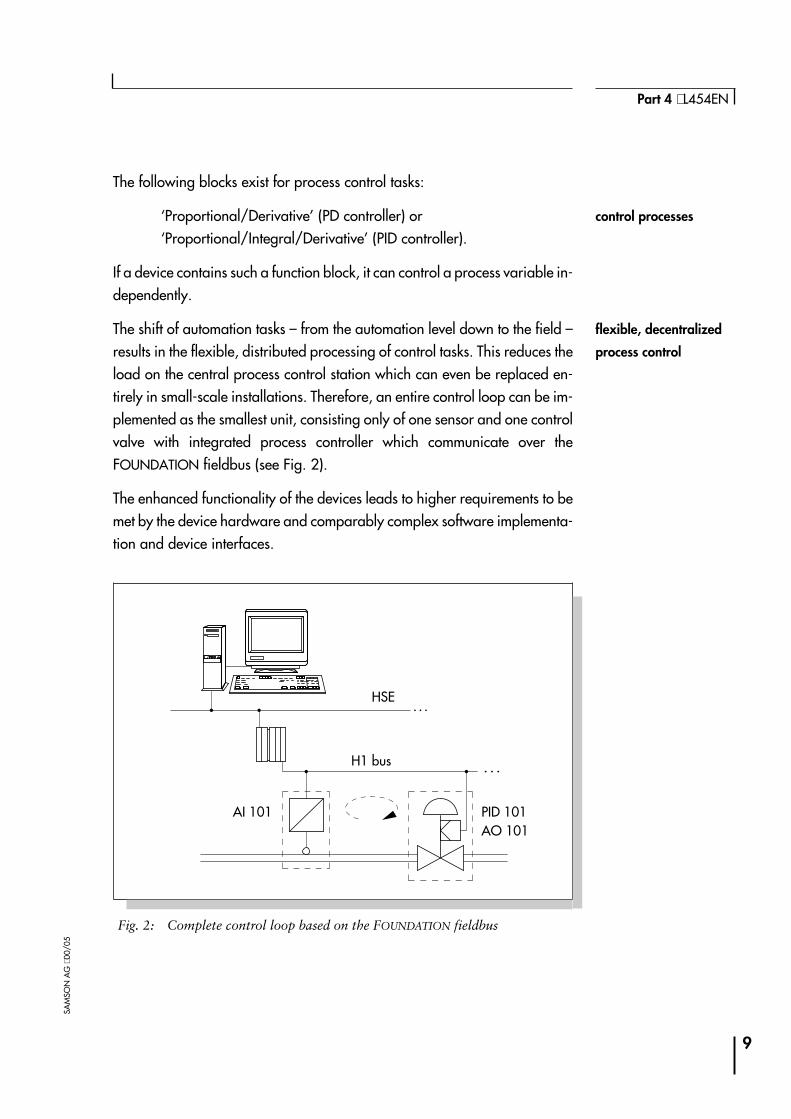
The shift of automation tasks – from the automation level down to the field –results in the flexible, distributed processing of control tasks. This reduces theload on the central process control station which can even be replaced en-tirely in small-scale installations. Therefore, an entire control loop can be im-plemented as the smallest unit, consisting only of one sensor and one controlvalve with integrated process controller which communicate over theFOUNDATION fieldbus (see Fig. 2).
The enhanced functionality of the devices leads to higher requirements to bemet by the device hardware and comparably complex software implementa-tion and device interfaces.
9
Part 4 ⋅ L454EN
SAM
SON
AG
⋅00/
05
Fig. 2: Complete control loop based on the FOUNDATION fieldbus
AI 101 PID 101AO 101
H1 bus
HSE
flexible, decentralized
process control
control processes
Layered communications model
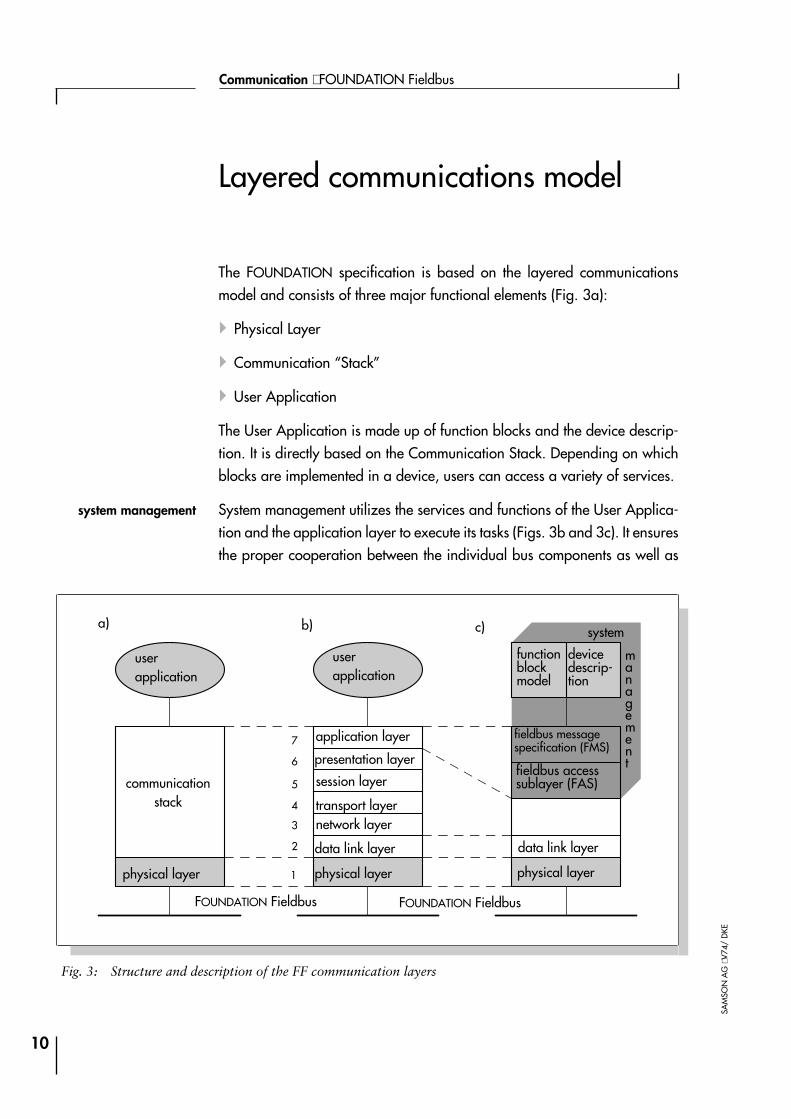
The FOUNDATION specification is based on the layered communicationsmodel and consists of three major functional elements (Fig. 3a):
4Physical Layer
4Communication “Stack”
4User Application
The User Application is made up of function blocks and the device descrip-tion. It is directly based on the Communication Stack. Depending on whichblocks are implemented in a device, users can access a variety of services.
System management utilizes the services and functions of the User Applica-tion and the application layer to execute its tasks (Figs. 3b and 3c). It ensuresthe proper cooperation between the individual bus components as well as
10
Communication ⋅ FOUNDATION Fieldbus
SAM
SON
AG
⋅V74
/D
KE
Fig. 3: Structure and description of the FF communication layers
userapplication
userapplication
functionblockmodel
devicedescrip-tion
system
management
application layer
presentation layer
session layer
transport layernetwork layer
data link layer
physical layerphysical layer physical layer
communicationstack
FOUNDATION Fieldbus FOUNDATION Fieldbus
data link layer
fieldbus accesssublayer (FAS)
fieldbus messagespecification (FMS)7
6
5
4
3
2
1
a) c)b)
system management

synchronizes the measurement and control tasks of all field devices with re-gard to time (see page 35).
The FOUNDATION fieldbus layered communications model is based on theISO/OSI reference model. As is the case for most fieldbus systems, and inaccordance with an IEC specification, layers three to six are not used. Thecomparison in Fig. 3 shows that the Communication Stack covers the tasks oflayers two and seven and that layer seven consists of the Fieldbus AccessSublayer (FAS) and the Fieldbus Message Specification (FMS) (see page 26and Lit. /3/).
11
Part 4 ⋅ L454EN
SAM
SON
AG
⋅00/
05
fieldbus specification
based on ISO/OSI com-
munication model

Physical layer
The specification of the FOUNDATION Fieldbus is not yet completed at thisstage. However, it is certain that the topology of a FF system complies withthe IEC Fieldbus model in many aspects.
The IEC fieldbus solves pending communication tasks by using two bus sys-tems, the slow, intrinsically safe H1 bus and the fast, higher-level H2 bus with1 to 2.5 MBit/s (see IEC fieldbus model /Lit. 4/).
The physical design of the H1 bus of the FOUNDATION fieldbus compliesexactly with the specifications of the IEC fieldbus model. The specification ofthe H2 bus is not yet completed and the publication of the preliminary speci-fication (PS) has been announced. However, it is certain that the High SpeedEthernet (HSE) will be used (Fig. 4).
12
Communication ⋅ FOUNDATION Fieldbus
SAM
SON
AG
⋅V74
/D
KE
Fig. 4: Structure of the FOUNDATION fieldbus
Teilnehmer 1user 1 user muser 2
switch
user nuser 1
user 2
High Speed Ethernet (HSE)(100 MBit/s, LWL)
intrinsicallysafe area
R RH1bus (31.25 kBit/s, IEC 61158-2)
bridge
IEC fieldbus
FOUNDATION fieldbus
H1 bus
The following summary gives a brief overview of the basic values and fea-tures of the H1 bus. For more details, refer to the various ‘ApplicationGuides’ of the Fieldbus FOUNDATION (e.g., AG 140, AG 163).
The H1 bus specification is based on the IEC 61158-2 (see Lit./2/):
4Manchester coding is used for data transfer. The data transfer rate is31.25 kBit/s.
4Proper communication requires that the field devices have enough volta-ge. Each device should have minimum 9 volts. To make sure that this re-quirement is met, software tools are available which calculate the resultingcurrents and terminal voltages based on the network topology, the line re-sistance and the supply voltage.
4The H1 bus allows the field devices to be powered over the bus. The powersupply unit is connected to the bus line in the same way (parallel) as a fielddevice. Field devices powered by supply sources other than the bus, mustbe additionally connected to their own supply sources.
4With the H1 bus it must be ensured that the maximum power consumptionof current consuming devices is lower than the electric power supplied bythe power supply unit.
13
Part 4 ⋅ L454EN
SAM
SON
AG
⋅00/
05
1..7: field devices
JB: junction box
H1 specification
based on IEC 61158-2
bus powered
field devices
12 3
4
7
6
5
JB
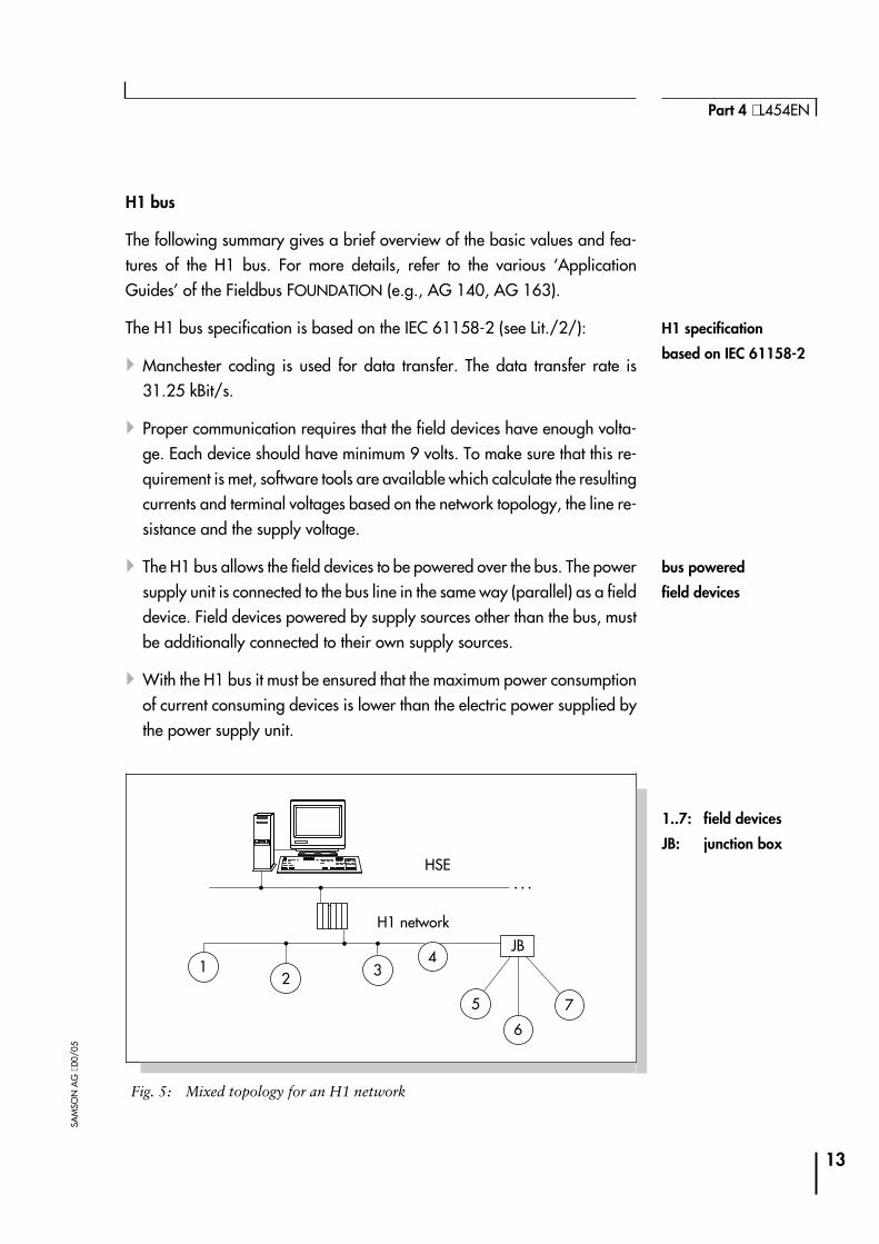
Fig. 5: Mixed topology for an H1 network
HSE
H1 network

4Network topologies used are usually line topology or, when equippedwith junction boxes, also star, tree or a combination of topologies (Fig. 5).The devices are best connected via short spurs using tee connectors to en-able connection/disconnection of the devices without interrupting commu-nication.
4The maximum length of a spur is limited to 120 meters and depends on thenumber of spurs used as well as the number of devices per spur (Fig. 6).
4Without repeaters, the maximum length of an H1 segment can be as longas 1900 meters. By using up to four repeaters, a maximum of 5*1900 m =9500 m can be jumpered. The short spurs from the field device to the busare included in this total length calculation.
14
Communication ⋅ FOUNDATION Fieldbus
SAM
SON
AG
⋅V74
/D
KE
No. ofdevices
1 deviceper spur
2 devicesper spur
3 devicesper spur
4 devicesper spur
25-32 1 m 1 m 1 m 1 m
19-24 30 m 1 m 1 m 1 m
15-18 60 m 30 m 1 m 1 m
13-14 90 m 60 m 30 m 1 m
1-12 120 m 90 m 60 m 30 m
Fig. 5: Length of spurs
Type A Type B Type C Type D
Cabledescription
shieldedtwistedpair
single ormulti-twistedpair with anoverall shield
multi-twistedpair withoutshield
multi-core,without twistedpairs, withoutshield
Size 0.8 mm2
(AWG 18)0.32 mm2
(AWG 22)0.13 mm2
(AWG 26)1.25 mm2
(AWG 16)
Max. lengthincl. spurs
1900 m 1200 m 400 m 200 m
Fig. 6: Fieldbus cable types and maximum bus lengths
spurs via T-connector

4The number of bus users per bus segment is limited to 32 in intrinsicallysafe areas. In explosion-hazardous areas, this number is reduced to onlya few devices due to power supply limitations (see EEx-i instrumentationbelow).
4Various types of cables are useable for fieldbus (Fig. 7). Type A is recom-mended as preferred fieldbus cable, and only this type is specified for themaximum bus length of 1900 m.
4Principally, there need to be two terminators per bus segment, one at ornear each end of a transmission line.
4 It is not imperative that bus cables be shielded, however, it is recommen-ded to prevent possible interferences and for best performance of thesystem.
• EEx-i instrumentation
The H1 bus can be designed intrinsically safe (Ex-i) to suit applications inhazardous areas. This requires that proper barriers be installed between thesafe and the explosion hazardous area (Fig. 8). In addition, only one device,the power supply unit, must supply the fieldbus with power. All other devicesmust always, i.e. also when transmitting and receiving data, function as cur-rent sinks.
Since the capacity of electrical lines is limited in intrinsically safe areas de-pending on the explosion group – IIB or IIC – (see Fig. 9), the number of de-
15
Part 4 ⋅ L454EN
SAM
SON
AG
⋅00/
05
Fig. 7: Elements for the intrinsically safe H1 bus
T TI.S.
interface
321ASG
T: terminator
I.S. intrinsically safe
barrier
SG: power supply
unit
A: field device in
safe area
1...3: intrinsically
safe field devices
ex areasafe area
two terminators per
bus segment
only one power
supply unit
limited electrical power
in ex areas
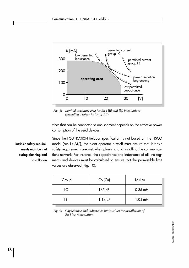
vices that can be connected to one segment depends on the effective powerconsumption of the used devices.
Since the FOUNDATION fieldbus specification is not based on the FISCOmodel (see Lit./4/), the plant operator himself must ensure that intrinsicsafety requirements are met when planning and installing the communica-tions network. For instance, the capacitance and inductance of all line seg-ments and devices must be calculated to ensure that the permissible limitvalues are observed (Fig. 10).
16
Communication ⋅ FOUNDATION Fieldbus
SAM
SON
AG
⋅V74
/D
KE
300
[mA]
200
100
00 10 20 30 [V]
Fig. 8: Limited operating area for Ex-i IIB and IIC installations(including a safety factor of 1.5)
Group Co (Ca) Lo (La)
IIC 165 nF 0.35 mH
IIB 1.14 µF 1.04 mH
Fig. 9: Capacitance and inductance limit values for installation ofEx-i instrumentation
permitted currentgroup IIC
permitted currentgroup IIB
power limitationbegrenzungoperating area
low permittedcapacitance
low permittedinductance
intrinsic safety require-
ments must be met
during planning and
installation
High Speed Ethernet (HSE)
The HSE is based on standard Ethernet technology. The required componentsare therefore widely used and are available at low costs. The HSE runs at100 Mbit/s and cannot only be equipped with electrical lines, but with opti-cal fiber cables as well.
The Ethernet operates by using random (not deterministic) CSMA bus access.This method can only be applied to a limited number of automation applica-tions because it requires real-time capability. The extremely high transmis-sion rate enables the bus to respond sufficiently fast when the bus load is lowand devices are only few. With respect to process engineering requirements,real-time requirements are met in any case.
If the bus load must be reduced due to the many connected devices, or if sev-eral HSE partial networks are to be combined to create a larger network,Ethernet Switches must be used (see Fig. 4). A switch reads the target addressof the data packets that must be forwarded and then passes the packets on tothe associated partial network. This way, the bus load and the resulting busaccess time can be controlled to best adapt it to the respective requirements.
Bridge to H1-HSE coupling
A communications network that consists of an H1 bus and an HSE networkresults in a topology as illustrated in Fig. 4. To connect the comparativelyslow H1 segments to the HSE network, coupling components, so-calledBridges, are required. Similar to HSE, the specification of this bus componenthas not been completed up to now.
A Bridge is used to connect the individual H1 buses to the fast High SpeedEthernet. The various data transfer rates and data telegrams must beadapted and converted, considering the direction of transmission. This way,powerful and widely branched networks can be installed in larger plants.
17
Part 4 ⋅ L454EN
SAM
SON
AG
⋅00/
05
standard available
Ethernet technology
real-time requirements
can be met
coupling components
required
adaptation of various
data rates and
telegrams
Communication stack
The field devices used with the FOUNDATION fieldbus are capable of assum-ing process control functions. This option is based on distributed communica-tion which ensures that
4each controlling field device can exchange data with other devices (e.g.reading measuring values, forwarding correction values),
4all field devices are served in time (‘in time’ meaning that the processing ofthe different control loops is not negatively influenced),
4 two or more devices never access the bus simultaneously.
To meet these requirements, the H1 bus of the FOUNDATION fieldbus uses acentral communication control system.
Link Active Scheduler – LAS
The Link Active Scheduler (LAS) controls and schedules the communicationon the bus (see page 19: Communication control). It controls the bus activitiesusing different commands which it broadcasts to the devices. Since the LASalso continuously polls unassigned device addresses, it is possible to connectdevices during operation and to integrate them in the bus communication.
Devices that are capable of becoming the LAS, are called ‘Link Master’. ‘Ba-sic devices’ do not have the capability to become LAS.
In a redundant system containing multiple Link Masters, one of the Link Mas-ters will become the LAS if the active LAS fails (fail-operational design).
18
Communication ⋅ FOUNDATION Fieldbus
SAM
SON
AG
⋅V74
/D
KE
distributed
communication
central
communication
control
fail-operational design

Communication control
The communication services of the FF specification utilize scheduled and un-scheduled data transmission. Time-critical tasks, such as the control of pro-cess variables, are exclusively performed by scheduled services, whereasparameterization and diagnostic functions are carried out using unsched-uled communication services.
• Scheduled data transmission
To solve communication tasks in time and without access conflicts, alltime-critical tasks are based on a strict transmission schedule. This scheduleis created by the system operator during the configuration of the FF system.
The LAS periodically broadcasts a synchronization signal (TD: Time Distribu-tion) on the fieldbus so that all devices have exactly the same data link time.In scheduled transmission, the point of time and the sequence are exactly de-fined. This is why it is called a deterministic system.
Fig. 11 presents the schedule for a system with two sensors and two controlvalves. The schedule determines when the devices process their functionblocks (AI, A0, PID) and when it is time to transmit data.
Each activity to be executed has been scheduled for a certain time. This timeis defined by an offset value which reflects the delay referred to the start ofthe schedule.
Based on this schedule, a transmission list is generated which defines when aspecific field device is prompted to send its data. Upon receipt of the mes-
19
Part 4 ⋅ L454EN
SAM
SON
AG
⋅00/
05
Device Type Action Offset
1 Sensor Execution AI (1)Transmission AI (1) of data
020
2 Sensor Execution AI (2)Transmission AI (2) of data
030
3 Control valve Execution PID (3)Execution AO (3)
4062
Fig. 10: Schedule for processing function blocks
scheduled or
unscheduled data
transmission
time-critical tasks
with a strict trans-
mission schedule
transmission list for
“publisher and
subscriber” method
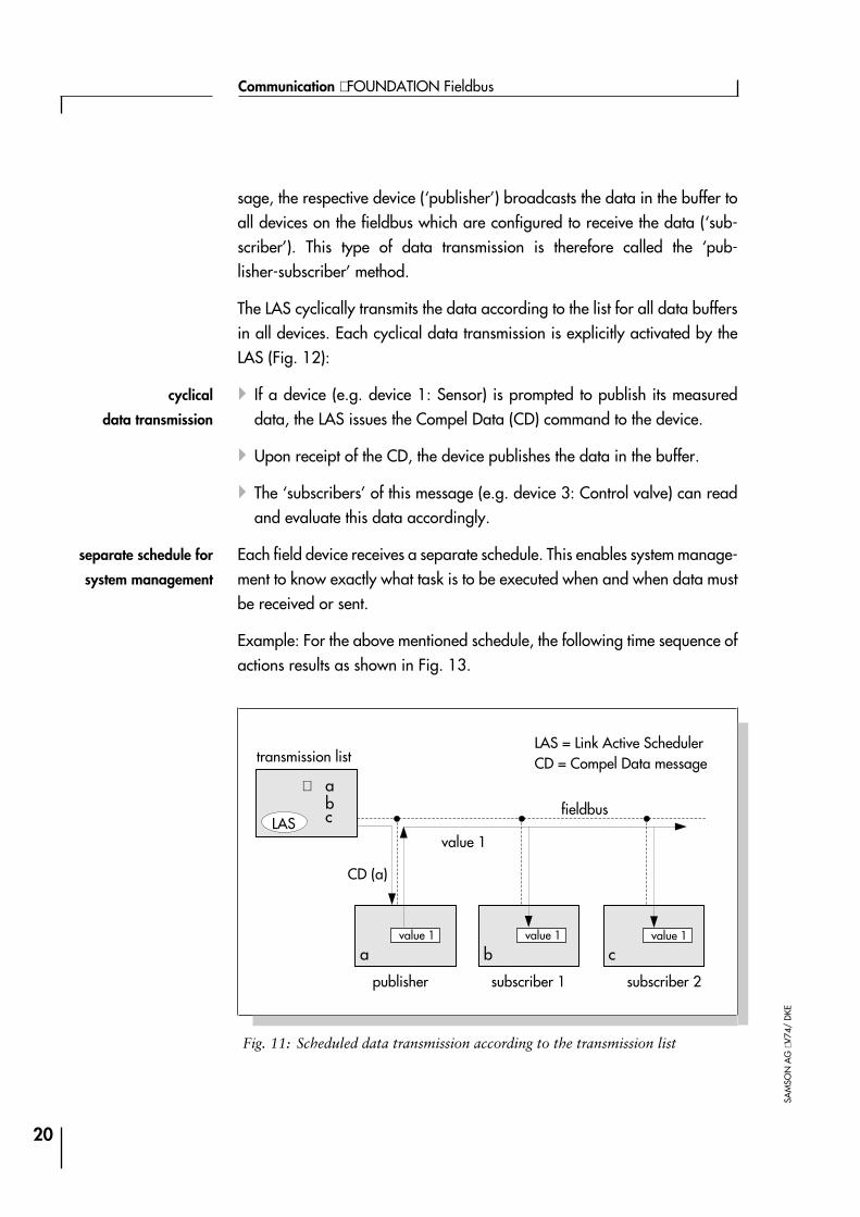
sage, the respective device (‘publisher’) broadcasts the data in the buffer toall devices on the fieldbus which are configured to receive the data (‘sub-scriber’). This type of data transmission is therefore called the ‘pub-lisher-subscriber’ method.
The LAS cyclically transmits the data according to the list for all data buffersin all devices. Each cyclical data transmission is explicitly activated by theLAS (Fig. 12):
4 If a device (e.g. device 1: Sensor) is prompted to publish its measureddata, the LAS issues the Compel Data (CD) command to the device.
4Upon receipt of the CD, the device publishes the data in the buffer.
4The ‘subscribers’ of this message (e.g. device 3: Control valve) can readand evaluate this data accordingly.
Each field device receives a separate schedule. This enables system manage-ment to know exactly what task is to be executed when and when data mustbe received or sent.
Example: For the above mentioned schedule, the following time sequence ofactions results as shown in Fig. 13.
20
Communication ⋅ FOUNDATION Fieldbus
SAM
SON
AG
⋅V74
/D
KE
Fig. 11: Scheduled data transmission according to the transmission list
transmission list
publisher subscriber 2subscriber 1
fieldbus
CD (a)
value 1
value 1
abc
⇒
LAS
LAS = Link Active SchedulerCD = Compel Data message
a b cvalue 1 value 1
cyclical
data transmission
separate schedule for
system management

4at zero time, sensors (1) and (2) start their measurements;
4at time 20, the LAS prompts the sensor (1) to send its measuring data sothat it can be read by the PID controller of the associated control valve (3);
4at time 30, the LAS prompts the sensor (2) to send its measuring data sothat it can be read by the PID controller of the associated control valve (4);
4at time 40, both control valves are processing their PID function blocks;
4at time 57, control valve 4 starts its travel process;
4at time 62, control valve 3 starts its travel process;
4at 140 time increments, the same actions are repeated.
21
Part 4 ⋅ L454EN
SAM
SON
AG
⋅00/
05
0 20 40 60 80 100 120 140 20 40 60 80 100 120 140
Fig. 12: Scheduled transmission and unscheduled communication
macrocycles:
device 1:device 2:
device 3:device 4:
LAS:
unscheduled communication in the breaks of scheduled c.
scheduled transmission of the AE(1) and AE(2)
AI(1)
AI(2)
PID(3) AO(3)
PD(4) AO(4)
AI(1)
AI(2)
PID(3) AO(3)
PD(4) AO(4)
cyclical sequence
scheduled cycle n scheduled cycle n+1
schedule

Each control loop accesses the bus only once for a short time. Therefore, thebus could be used for many more control loops as well as for other activities.This shows that the distributed control strategy reduces the number of datatransmissions over the bus to a minimum.
22
Communication ⋅ FOUNDATION Fieldbus
SAM
SON
AG
⋅V74
/D
KE
number of data
transmissions
considerably reduced

• Unscheduled transmission
Device parameters and diagnostic data must be transmitted when needed,i.e. on request. The transmission of this data is not time-critical. For suchcommunication tasks, the FOUNDATION fieldbus is equipped with the optionof unscheduled data transmission.
Unscheduled data transmission is exclusively restricted to the breaksinbetween scheduled transmission. The LAS grants permission to a device touse the fieldbus for unscheduled communication tasks if no scheduled datatransmission is active (see Fig. 14 below).
Permission for a certain device to use the bus is granted by the LAS when it is-sues a pass token (PT command) to the device. The pass token is sent aroundto all devices entered in the ‘Live List’ (Fig. 14) which is administrated by theLAS. Each device may use the bus as long as required until it either returnsthe token, or until the maximum granted time to use the token has elapsed.
The Live List is continuously updated by the LAS. The LAS sends a specialcommand, the Probe Node (PN), to the addresses not in the Live List, search-ing for newly added devices. If a device returns a Probe Response (PR) mes-sage, the LAS adds the device to the Live List where it receives the pass tokenfor unscheduled communication according to the order submitted for trans-
23
Part 4 ⋅ L454EN
SAM
SON
AG
⋅00/
05
Fig. 13: Unscheduled data transmission with token
live list
receives tokenand sends
fieldbus
PT (y)
data
xyz
⇒LAS
LAS = Link Active SchedulerPT = Pass Token message
x y z
datadata
data transmission
on request
token passing
over the ‘Live List’
mission in the Live List. Devices which do not respond to the PT command orreturn the token after three successive tries are removed from the Live List.
Whenever a device is added or removed from the Live List, the LAS broad-casts these changes to all devices. This allows all Link Masters to maintain acurrent copy of the Live List so that they can become the LAS without the lossof information.
24
Communication ⋅ FOUNDATION Fieldbus
SAM
SON
AG
⋅V74
/D
KE
copy of Live List
to all Link Masters
• Communication schedule
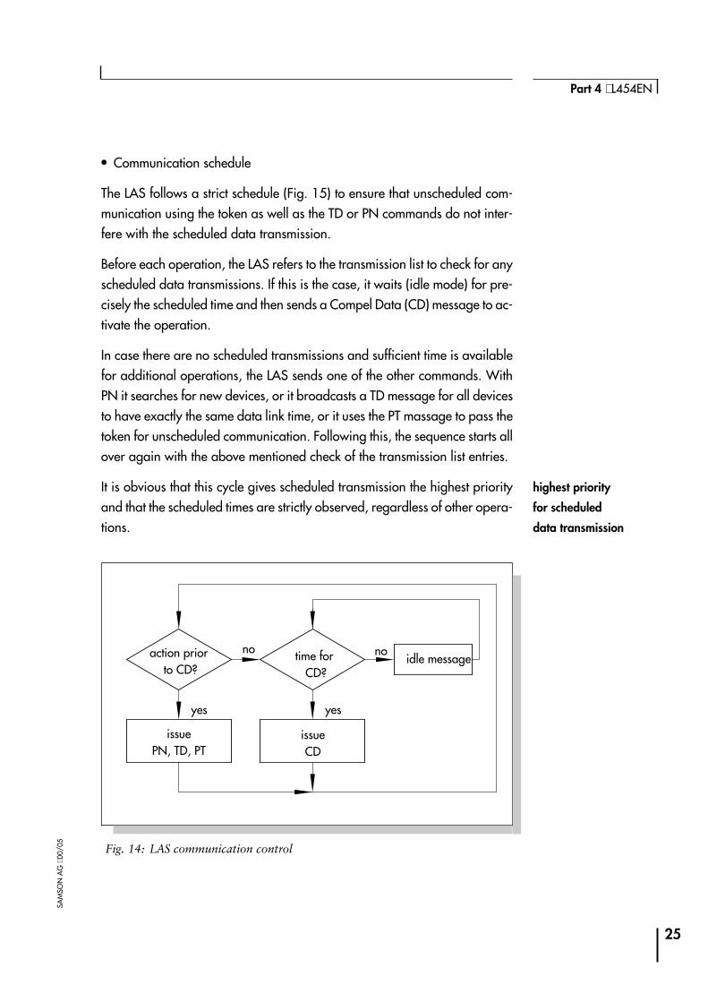
The LAS follows a strict schedule (Fig. 15) to ensure that unscheduled com-munication using the token as well as the TD or PN commands do not inter-fere with the scheduled data transmission.
Before each operation, the LAS refers to the transmission list to check for anyscheduled data transmissions. If this is the case, it waits (idle mode) for pre-cisely the scheduled time and then sends a Compel Data (CD) message to ac-tivate the operation.
In case there are no scheduled transmissions and sufficient time is availablefor additional operations, the LAS sends one of the other commands. WithPN it searches for new devices, or it broadcasts a TD message for all devicesto have exactly the same data link time, or it uses the PT massage to pass thetoken for unscheduled communication. Following this, the sequence starts allover again with the above mentioned check of the transmission list entries.
It is obvious that this cycle gives scheduled transmission the highest priorityand that the scheduled times are strictly observed, regardless of other opera-tions.
25
Part 4 ⋅ L454EN
SAM
SON
AG
⋅00/
05 Fig. 14: LAS communication control
action priorto CD?
time forCD?
issuePN, TD, PT
issueCD
idle message
yes
no
yes
no
highest priority
for scheduled
data transmission

Application layer
The Fieldbus Access Sublayer (FAS) and Fieldbus Message Specification(FMS) layer form the interface between the data link layer and the user appli-cation (see Fig. 3). The services provided by FAS and FMS are invisible forthe user. However, the performance and functionality of the communicationsystem considerably depends on these services.
• Fieldbus Access Sublayer (FAS)
FAS services create Virtual Communication Relationships (VCR) which areused by the higher-level FMS layer to execute its taks. VCRs describe differ-ent types of communication processes and enable the associated activities tobe processed more quickly. FF communication utilizes three different VCRtypes as follows (Fig. 16).
4The Publisher/Subscriber VCR Type is used to transmit the input and out-put data of function blocks. As described above, scheduled data transmis-sion with the CD command is based on this type of VCR. However, thePublisher/Subscriber VCR is also available for unscheduled data trans-mission; for instance, if a subscriber requests measuring or positioningdata from a device.
26
Communication ⋅ FOUNDATION Fieldbus
SAM
SON
AG
⋅V74
/D
KE
Client/Server Report Distribution Publisher/Subscriber
Operatorcommunication
Event notification, alarms,trend reports
Data publication
Set point changesMode and device datachangesUpload/downloadAdjusting alarm valuesAccess display viewsRemote diagnostics
Send process alarms tooperator consoles
Send trend reports to datahistorians
Send actual value of atransmitter to PID blockand operator console
Fig. 15: Virtual Communication Relationships of the FAS
interface between
data link layer and
user application
Virtual Communication
Relationship VCR
transmitting input/
output data of
function blocks
4The Client/Server VCR Type is used for unscheduled, user-initiated com-munication based on the PT command. If a device (client) requests datafrom another device, the requested device (server) only responds when itreceives a PT from the LAS.The Client/Server communication is the basis for operator initiated re-quests, such as set point changes, tuning parameter access and change,diagnosis, device upload and download, etc.
4Report Distribution communication is used to send alarm or other eventnotifications to the operator consoles or similar devices. Data transmissionis unscheduled when the device receives the PT command together with thereport (trend or event notification). Fieldbus devices that are configured toreceive the data await and read this data.
• Fieldbus Message Specification (FMS)
FMS provides the services for standardized communication. Data types thatare communicated over the fieldbus are assigned to certain communicationservices. For a uniform and clear assignment, object descriptions are used.Object descriptions contain definitions of all standard transmission messageformats, but also include application specific data. For each type of objectthere are special, predefined communication services.
Object descriptions are collected together in a structure called an object dic-tionary. The object description is identified by its index (Fig. 17).
4 Index 0, called the object dictionary header, provides a description of thedictionary itself.
4 Indices between 1 and 255 define standard data types that are used tobuild more complex object descriptions.
4The User Application object descriptions can start at any index above255.
27
Part 4 ⋅ L454EN
SAM
SON
AG
⋅00/
05
unscheduled
communication
basis for
operator-initiated
requests
communication services
are assigned to each
data type
access via the object
dictionary
standard data types
User Application
object descriptions

The FMS defines ‘Virtual Field Devices’ (VFD) which are used to make the ob-ject descriptions of a field device as well as the associated device data avail-able over the entire network.
The VFDs and the object description can be used to remotely access all localfield device data from any location by using the associated communicationservices.
28
Communication ⋅ FOUNDATION Fieldbus
SAM
SON
AG
⋅V74
/D
KE
Fig. 16: Access to the object dictionary using indices
...
object description 1
object description 2
object description n
index 0
index 1
index 2
index n
•••
virtual field devices
remote access
to all data
User application
An important criterion for a fieldbus system to be accepted by the market isthe interoperability of the devices. Interoperability is the capability of devicesof different manufacturers to communicate with each other. In addition, itmust be ensured that a component from one manufacturer can be substitutedwith that of another, also called interchangeability.
This requires an open protocol specification which defines uniform devicefunctions and application interfaces. Other devices on the network and ap-plication programs can use these interfaces to access the functions and pa-rameters of the field devices. The FOUNDATION fieldbus makes thesedefinitions based on blocks and device descriptions.
Block model
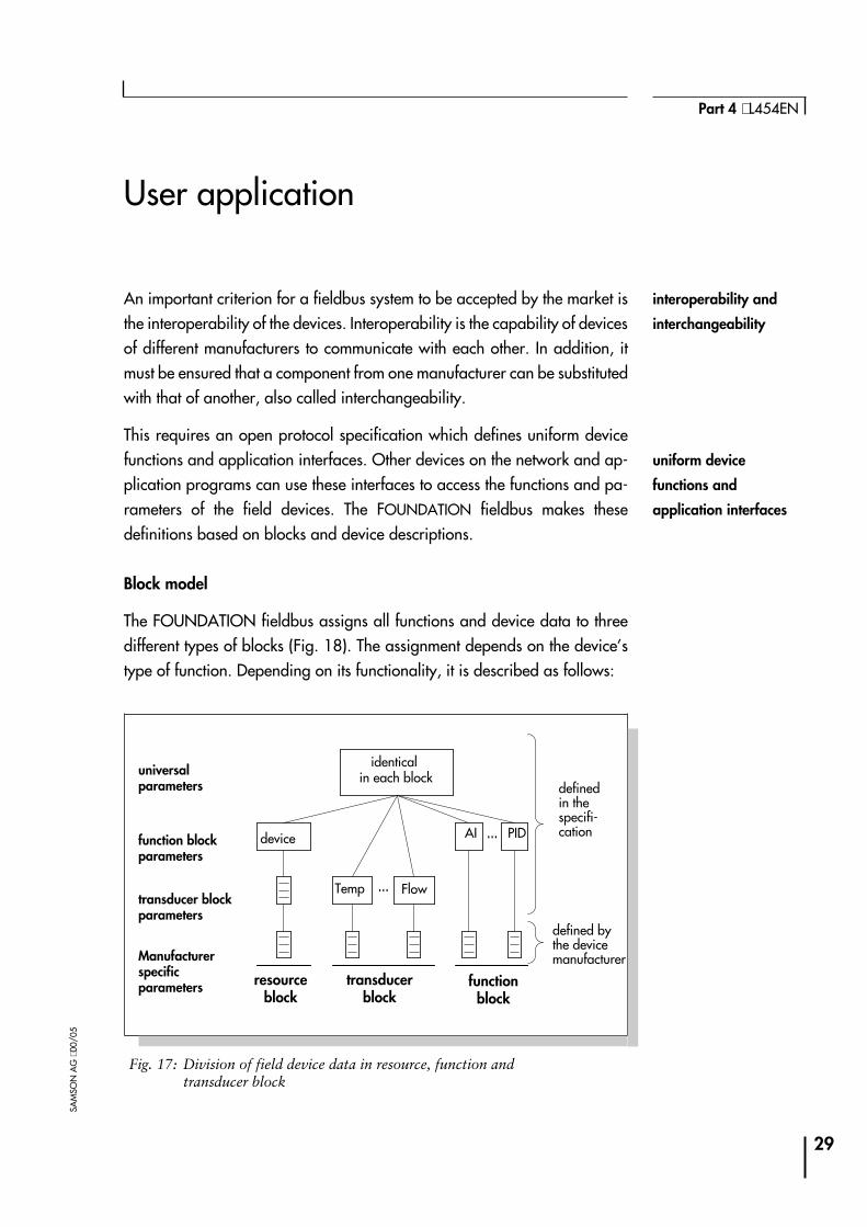
The FOUNDATION fieldbus assigns all functions and device data to threedifferent types of blocks (Fig. 18). The assignment depends on the device’stype of function. Depending on its functionality, it is described as follows:
29
Part 4 ⋅ L454EN
SAM
SON
AG
⋅00/
05
Fig. 17: Division of field device data in resource, function andtransducer block
universalparameters
Manufacturerspecificparameters
transducer blockparameters
function blockparameters
device AI PID
Temp Flow
identicalin each block
resourceblock
transducerblock
functionblock
definedin thespecifi-cation
defined bythe devicemanufacturer
interoperability and
interchangeability
uniform device
functions and
application interfaces
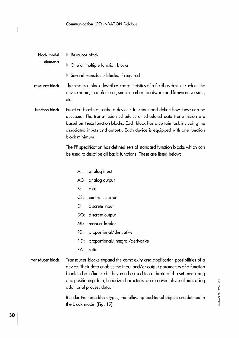
4Resource block
4One or multiple function blocks
4Several transducer blocks, if required
The resource block describes characteristics of a fieldbus device, such as thedevice name, manufacturer, serial number, hardware and firmware version,etc.
Function blocks describe a device’s functions and define how these can beaccessed. The transmission schedules of scheduled data transmission arebased on these function blocks. Each block has a certain task including theassociated inputs and outputs. Each device is equipped with one functionblock minimum.
The FF specification has defined sets of standard function blocks which canbe used to describe all basic functions. These are listed below:
AI: analog input
AO: analog output
B: bias
CS: control selector
DI: discrete input
DO: discrete output
ML: manual loader
PD: proportional/derivative
PID: proportional/integral/derivative
RA: ratio
Transducer blocks expand the complexity and application possibilities of adevice. Their data enables the input and/or output parameters of a functionblock to be influenced. They can be used to calibrate and reset measuringand positioning data, linearize characteristics or convert physical units usingadditional process data.
Besides the three block types, the following additional objects are defined inthe block model (Fig. 19).
30
Communication ⋅ FOUNDATION Fieldbus
SAM
SON
AG
⋅V74
/D
KE
resource block
function block
transducer block
block model
elements
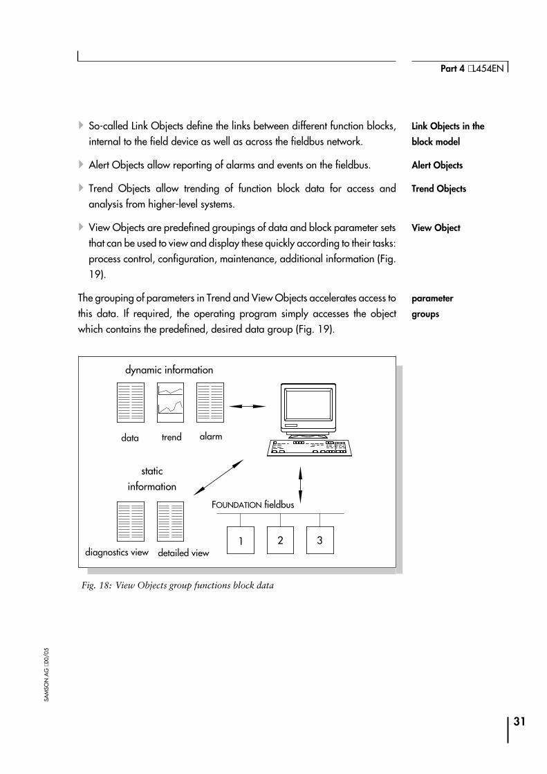
4So-called Link Objects define the links between different function blocks,internal to the field device as well as across the fieldbus network.
4Alert Objects allow reporting of alarms and events on the fieldbus.
4Trend Objects allow trending of function block data for access andanalysis from higher-level systems.
4View Objects are predefined groupings of data and block parameter setsthat can be used to view and display these quickly according to their tasks:process control, configuration, maintenance, additional information (Fig.19).
The grouping of parameters in Trend and View Objects accelerates access tothis data. If required, the operating program simply accesses the objectwhich contains the predefined, desired data group (Fig. 19).
31
Part 4 ⋅ L454EN
SAM
SON
AG
⋅00/
05
Fig. 18: View Objects group functions block data
dynamic information
staticinformation
data trend alarm
diagnostics view detailed view1 2 3
FOUNDATION fieldbus
Link Objects in the
block model
Alert Objects
Trend Objects
View Object
parameter
groups
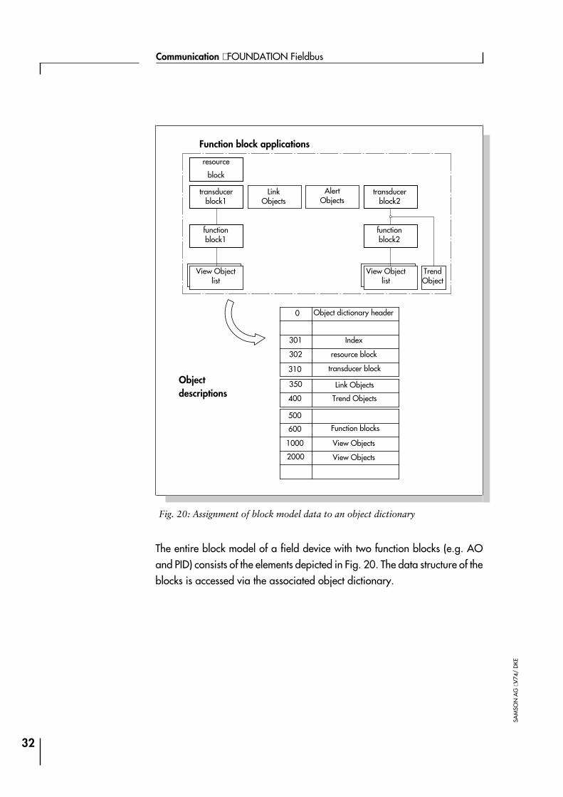
The entire block model of a field device with two function blocks (e.g. AOand PID) consists of the elements depicted in Fig. 20. The data structure of theblocks is accessed via the associated object dictionary.
32
Communication ⋅ FOUNDATION Fieldbus
SAM
SON
AG
⋅V74
/D
KEFig. 20: Assignment of block model data to an object dictionary
resource
block
transducerblock2
transducerblock1
LinkObjects
AlertObjects
functionblock1
functionblock2
View Objectlist
View Objectlist
TrendObject
Function block applications
Objectdescriptions
Object dictionary header
Index
resource block
transducer block
Link Objects
Trend Objects
Function blocks
View Objects
View Objects
0
301
310
302
350
400
600
1000
2000
500
Device descriptions
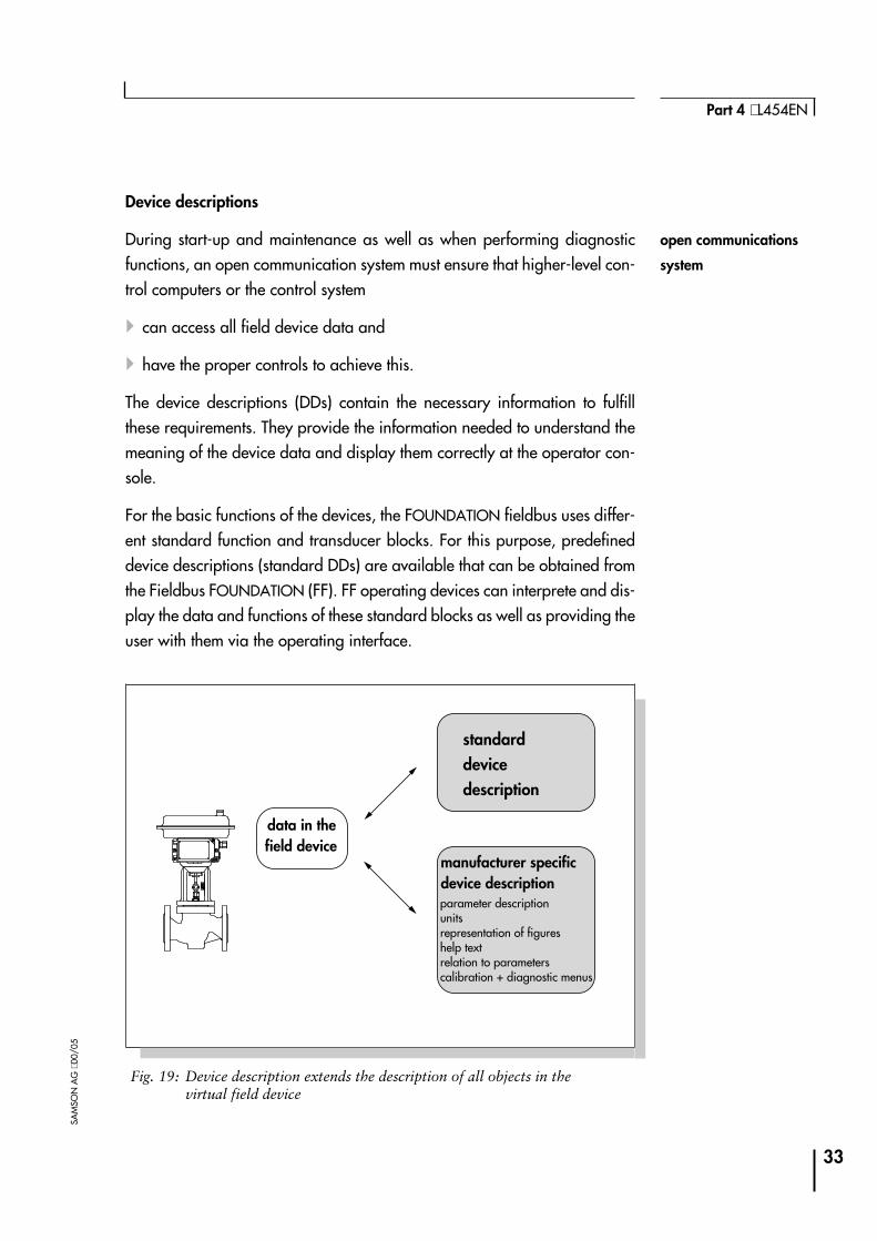
During start-up and maintenance as well as when performing diagnosticfunctions, an open communication system must ensure that higher-level con-trol computers or the control system
4can access all field device data and
4have the proper controls to achieve this.
The device descriptions (DDs) contain the necessary information to fulfillthese requirements. They provide the information needed to understand themeaning of the device data and display them correctly at the operator con-sole.
For the basic functions of the devices, the FOUNDATION fieldbus uses differ-ent standard function and transducer blocks. For this purpose, predefineddevice descriptions (standard DDs) are available that can be obtained fromthe Fieldbus FOUNDATION (FF). FF operating devices can interprete and dis-play the data and functions of these standard blocks as well as providing theuser with them via the operating interface.
33
Part 4 ⋅ L454EN
SAM
SON
AG
⋅00/
05
Fig. 19: Device description extends the description of all objects in thevirtual field device
data in thefield device
parameter descriptionunitsrepresentation of figureshelp textrelation to parameterscalibration + diagnostic menus
standarddevicedescription
manufacturer specificdevice description
open communications
system
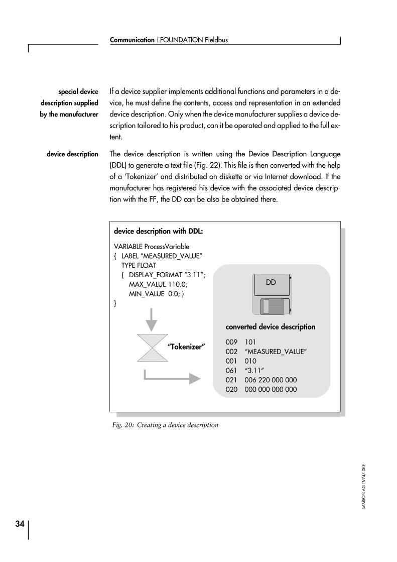
If a device supplier implements additional functions and parameters in a de-vice, he must define the contents, access and representation in an extendeddevice description. Only when the device manufacturer supplies a device de-scription tailored to his product, can it be operated and applied to the full ex-tent.
The device description is written using the Device Description Language(DDL) to generate a text file (Fig. 22). This file is then converted with the helpof a ‘Tokenizer’ and distributed on diskette or via Internet download. If themanufacturer has registered his device with the associated device descrip-tion with the FF, the DD can be also be obtained there.
34
Communication ⋅ FOUNDATION Fieldbus
SAM
SON
AG
⋅V74
/D
KE
Fig. 20: Creating a device description
device description with DDL:
VARIABLE ProcessVariable{ LABEL “MEASURED_VALUE”
TYPE FLOAT{ DISPLAY_FORMAT “3.11”;
MAX_VALUE 110.0;MIN_VALUE 0.0; }
}
converted device description
009 101002 “MEASURED_VALUE”001 010061 “3.11”021 006 220 000 000020 000 000 000 000
“Tokenizer”
DD
device description
special device
description supplied
by the manufacturer
System management
The system management of each device has the following tasks:
4Synchronization of the relevant device activities in time, i.e. according tothe predefined transmission schedule (see page 25).
4Cyclical processing of the transmission list (LAS only) within the predefi-ned time schedule (page 19).
Further tasks performed by system management are the following.
4Automatic assignment of the LAS function to another Link Master, if the ac-tive LAS fails.
4Application clock synchronizations.
4Automatic address assignment for new devices on the communicationsnetwork.
The automatic assignment of device addresses enables a device to be as-signed a unique network address while the process is active.
For the software controlled address assignment, special default addressesare reserved over which the new devices can be accessed. After the internalphysical device tag as well as a unique and new bus address have been as-signed to the new device, it is integrated in the communications network. The‘default address’ is then available again for the assignment of more devices.
35
Part 4 ⋅ L454EN
SAM
SON
AG
⋅00/
05
system management
tasks
automatic address
assignment

System configuration
Scheduled communication as well as all fieldbus devices must beparameterized before the first start-up (Fig. 23). A configuration tool, e.g.the NI-FBUS Configurator by National Instruments, is required for this pur-pose.
The device description of all used devices must be entered into the configura-tion device. The software must either be able to access the DDs in predefinedlibraries, or they must be loaded via external data carriers (e.g. via diskette).
The configuration software determines how and with which devices the mea-surement and control tasks of a plant are processed by interconnecting thefunction blocks of the field devices. This job can be easily performed bymeans of a graphical user interface. All that needs to be done is to connectthe inputs and outputs of the corresponding block symbols.
Fig. 24 shows an example of cascade control where the sensor output valueis connected to a PID function block. This block can be implemented, for in-stance, in a control valve’s positioner. The positioner output acts locally onthe analog output of the final controlling element, so that no data has to be
36
Communication ⋅ FOUNDATION Fieldbus
SAM
SON
AG
⋅V74
/D
KE
Fig. 21: System configuration by means of a configuration device
configuration device devicedescription
FF fieldbus
con-figuringthe Link Master
configur-ing simple devices
configuration device
loads the device
description
connection of
function blocks

transmitted via the fieldbus. The configuration shown corresponds to the con-trol loop example illustrated in Fig. 2.
Besides connecting the function blocks, the network configurator also config-ures the individual loop execution rate. Based on this data and the wiring di-agram, the configuration tool generates the information needed to controlthe devices and the communication.
Finally, this data is entered into the individual field devices. During this pro-cess, the LAS is configured and all Link Masters receive the current transmis-sion list for scheduled data transmission.
The system configuration is now complete so that the system management ofthe LAS and of the other field devices can take control over the system.
37
Part 4 ⋅ L454EN
SAM
SON
AG
⋅00/
05
Fig. 22: Connection of function blocks for cascade control (via software)
OUTAI
PID OUT
IN
sensorcontrol valve withLink Master function
BKCAL_OUT
BKCAL_IN
CAS_IN
AO
control loop execution
rate
configuration of LAS
and Link Masters
Appendix A1:Additional literature
[1] Digital SignalsTechnical Information L 150 EN; SAMSON AG
[2] Serial Data TransmissionTechnical Information L 153 EN; SAMSON AG
[3] Communication NetworksTechnical Information L 155 EN; SAMSON AG
[4] Communication in the FieldTechnical Information L 450 EN; SAMSON AG
[5] HART CommunicationsTechnical Information L 452 EN; SAMSON AG
[6] PROFIBUS-PATechnical Information L 453 EN; SAMSON AG
38
Communication ⋅ FOUNDATION Fieldbus
SAM
SON
AG
⋅V74
/D
KE
APP
ENDI
X
Figures
Fig. 1: Logo of Fieldbus FOUNDATION members . . . . . . . . . . . 7
Fig. 2: Complete control loop based on the FOUNDATION fieldbus . . . 9
Fig. 3: Structure and description of the FF communication layers . . . 10
Fig. 4: Structure of the FOUNDATION fieldbus . . . . . . . . . . . . 12
Fig. 5: Mixed topology for an H1 network . . . . . . . . . . . . . . 13
Fig. 6: Lengths of spurs. . . . . . . . . . . . . . . . . . . . . . . 14
Fig. 7: Fieldbus cable types and maximum bus lengths . . . . . . . . 14
Fig. 8: Elements for the intrinsically safe H1 bus . . . . . . . . . . . 15
Fig. 9: Limited operating area for Ex-i IIB and IIC installations(including a safety factor of 1.5) . . . . . . . . . . . . . . . 16
Fig. 10: Capacitance and inductance limit values for Ex-i installations . 16
Fig. 11: Schedule for processing function blocks. . . . . . . . . . . . 19
Fig. 12: Scheduled data transmission according to the transmission list . 20
Fig. 13: Scheduled transmission and unscheduled communication . . . 21
Fig. 14: Unscheduled data transmission with token . . . . . . . . . . 23
Fig. 15: LAS communication control . . . . . . . . . . . . . . . . . 25
Fig. 16: Virtual Communication Relationships of the FAS . . . . . . . 26
Fig. 17: Access to the object dictionary using indices . . . . . . . . . 28
Fig. 18: Division of field device data in resource, functionand transducer block . . . . . . . . . . . . . . . . . . . . 29
Fig. 19: View Object group functions block data . . . . . . . . . . . 31
Fig. 20: Assignment of block model data to an object dictionary . . . . 32
Fig. 21: Device description extends the description of all objects in thevirtual field device. . . . . . . . . . . . . . . . . . . . . . 33
39
Part 4 ⋅ L454EN
SAM
SON
AG
⋅00/
05
FIG
URE
S
Fig. 22: Creating a device description . . . . . . . . . . . . . . . . 34
Fig. 23: System configuration by means of a configuration device . . . 36
Fig. 24: Connection of function blocks for cascade control (via software) 37
40
Communication ⋅ FOUNDATION Fieldbus
SAM
SON
AG
⋅V74
/D
KE
FIG
URE
S

41
Part 4 ⋅ L454EN
SAM
SON
AG
⋅00/
05
NO
TES

42
Communication ⋅ FOUNDATION Fieldbus
SAM
SON
AG
⋅V74
/D
KE
NO
TES
SAMSON right on quality course
ISO 9001Our quality assurance system,
approved by BVQi, guarantees a high
quality of products and services.

SAMSON AG ⋅ MESS- UND REGELTECHNIK ⋅ Weismüllerstraße 3 ⋅ D-60314 Frankfurt am MainTelefon (069) 4 00 90 ⋅ Telefax (069) 4 00 95 07 ⋅ Internet: http://www.samson.de
2000
/05
⋅L45
4EN