FortiSwitch Standalone Mode Administration...
21
FortiSwitch Standalone Mode Administration Guide
Transcript of FortiSwitch Standalone Mode Administration...

FortiSwitch Standalone Mode
Administration Guide

FortiSwitch Standalone Mode Administration Guide
September 19, 2014
Copyright© 2014 Fortinet, Inc. All rights reserved. Fortinet®, FortiGate®, FortiCare® and
FortiGuard®, and certain other marks are registered trademarks of Fortinet, Inc., and other
Fortinet names herein may also be registered and/or common law trademarks of Fortinet. All
other product or company names may be trademarks of their respective owners. Performance
and other metrics contained herein were attained in internal lab tests under ideal conditions,
and actual performance and other resultsmay vary. Network variables, different network
environments and other conditions may affect performance results. Nothing herein represents
any binding commitment by Fortinet, and Fortinet disclaims all warranties, whether express or
implied, except to the extent Fortinet enters a binding written contract, signed by Fortinet’s
General Counsel, with a purchaser that expressly warrants that the identified product will
perform according to certain expressly-identified performance metrics and, in such event, only
the specific performance metrics expressly identified in such binding written contract shall be
binding on Fortinet. For absolute clarity, any such warranty will be limited to performance in the
same ideal conditions as in Fortinet’s internal lab tests. Fortinet disclaims in full any covenants,
representations,and guarantees pursuant hereto, whether express or implied. Fortinet reserves
the right to change, modify, transfer, or otherwise revise this publication without notice, and the
most current version of the publication shall be applicable.
Technical Documentation docs.fortinet.com
Knowledge Base kb.fortinet.com
Customer Service & Support support.fortinet.com
Training Services training.fortinet.com
FortiGuard fortiguard.com
Document Feedback [email protected]

Table of Contents
Change Log....................................................................................................... 4
Introduction....................................................................................................... 5Supported Models ................................................................................................... 5
Before You Begin..................................................................................................... 5
How this Guide is Organized ................................................................................... 5
System Settings................................................................................................ 6Configuring the Management Ports......................................................................... 6
Example Configurations..................................................................................... 6
Configuring Static Routing for the Internal Management Port .............................. 10
Ports ................................................................................................................ 11Configuring a Port Mirror ....................................................................................... 11
802.1x............................................................................................................... 12Authenticating with a RADIUS server .................................................................... 12
Example Configuration..................................................................................... 12
LACP Mode ..................................................................................................... 14Configuring the Trunk/LAG Ports .......................................................................... 14
Example Configuration..................................................................................... 14
Viewing the Configured Trunk ............................................................................... 16
TACACS........................................................................................................... 17Administrative Accounts ........................................................................................ 17
Configuring an Access Profile for Admin Accounts......................................... 17
Configuring a TACACS Admin Account........................................................... 17
User Accounts ....................................................................................................... 18
Configuring a User Account............................................................................. 18
Configuring a User Group................................................................................ 18
Example Configuration .......................................................................................... 18
Power over Ethernet ...................................................................................... 20Enabling PoE on a Port.......................................................................................... 20
Determining the PoE Power Capacity ................................................................... 20
Reset the PoE Power on a Port ............................................................................. 20
Page 3

Change Log
Date Change Description
Sept 19, 2014 Initial release.
Page 4

Introduction
Welcome and thank you for selecting Fortinet products for your network configuration.
This guide contains information about the administration of a FortiSwitch unit in standalone
mode. In standalone mode, a FortiSwitch is managed by connected directly to the unit, either
using the web-based manager (also known as the GUI) or the CLI.
If you will be managing your FortiSwitch unit using a FortiGate, please see the guide Managing a FortiSwitch unit with a FortiGate.
Supported Models
This guide is for all FortiSwitch models that are supported by FortiSwitchOS. This includes the
following models:
FortiSwitch-28C, FortiSwitch-108D-POE, FortiSwitch-124D, FortiSwitch-124D-POE,
FortiSwitch Rugged-124D, FortiSwitch-224D-POE, FortiSwitch-324B-POE,
FortiSwitch-348B, FortiSwitch-448B, FortiSwitch-1024D, FortiSwitch-1048D, and
FortiSwitch-3032D
Before You Begin
Before you start administrating your FortiSwitch unit, it is assumed that you have completed the
initial configuration of the FortiSwitch unit, as outlined in the QuickStart Guide for your
FortiSwitch model and have administrative access to the FortiSwitch unit’s web-based manager
and CLI.
How this Guide is Organized
This guide is organized into the following chapters:
• System Settings contains information about the initial configuration of your FortiSwitch unit.
• Ports contains information on configuring your FortiSwitch’s ports.
• 802.1x contains information on using 802.1x protocol.
• LACP Mode contains information on using a FortiSwitch in Link Aggregation Control
Protocol (LACP) mode.
• TACACS contains information on using TACACS authetication with your FortiSwitch unit.
• Power over Ethernet contains information on using Power over Ethernet (PoE) with your
FortiSwitch.
Page 5

System Settings
This chapter contains information about the initial configuration of your FortiSwitch unit.
Configuring the Management Ports
Using the web-based manager:
First start by editing the default internal interface’s configuration.
1. Go to System > Network > Interface and edit the internal interface.
2. Assign an IP/Netmask.
3. Set Administrative Access to use the desired protocols to connect to the interface.
4. Select OK.
Next, create a new interface to be used for management.
1. Go to System > Network > Interface and select Create New to create a management VLAN.
2. Give the interface an appropriate name.
3. Set Interface to internal.
4. Set a VLAN ID.
5. Assign an IP/Netmask.
6. Set Administrative Access to use the desired protocols to connect to the interface.
7. Select OK.
Using the CLI:
config system interfaceedit internal
set ip <address>set allowaccess <access_types>set type physical
nextedit <name>
set ip <address>set allowaccess <access_types>set interface internalset vlanid 10
endend
Example Configurations
The following are four example configurations for management ports, with the CLI syntax
shown to create them.
Page 6

Example 1: Port 48 as an inbound management interface
In this example, a physical port is used as an inbound management interface. Also, the FortiSwitch in the example has no default VLAN configured to connect its internal interface to any physical port.
Figure 1: Using Port 48 of a FortiSwitch-448B unit
Syntax
config system interfaceedit internal
set type physicalnextedit mgmt-vlan
set ip 10.105.142.22 255.255.255.0set allowaccess ping https sshset interface "internal"set vlanid 4090
nextend
Port 48 used as an
inbound management interface
System Settings Page 7 Managing a FortiSwitch unit with a FortiGate

config switch interfaceedit port48
set native-vlan 4090set stp-state disabled
nextedit uplink1nextedit uplink2nextedit internal
set native-vlan 4095set allowed-vlans 4090set stp-state disabled
endend
Example 2: Internal interface as an inbound management interface
In this example, the internal interface is used as an inbound management interface. Also, the
FortiSwitch has a default VLAN across all physical ports and its internal port.
Figure 2: Using the internaI interface of a FortiSwitch-108D-POE
Syntax
config system interfaceedit internal
set ip 192.168.1.99 255.255.255.0set allowaccess ping https http sshset type physical
endend
Port 1 (part of the internal interface)
used as an inband management interface
System Settings Page 8 Managing a FortiSwitch unit with a FortiGate

Example 3: WAN interface as an inbound management port
In this example, the WAN interface is used as an inbound management port.
Figure 3: WAN interface of a FortiSwitch-28C
Syntax
config system interfaceedit wan2
set ip 10.105.142.10 255.255.255.0set allowaccess ping https sshset type physical
nextedit wan1
set mode dhcpset allowaccess ping https sshset type physicalset defaultgw enable
nextedit internal
set type physicalend
end
Example 4: Out of band management interface
In the example, an out of band management interface is used as the dedicated management
port.
WAN 2 port used as an
inbound management port
System Settings Page 9 Managing a FortiSwitch unit with a FortiGate

Figure 4: Out of band management on a FortiSwitch-1024D
Syntax
config system interfaceedit mgmt
set ip 10.105.142.19 255.255.255.0set allowaccess ping https http ssh snmp telnetset type physical
nextedit internal
set type physicalend
end
Configuring Static Routing for the Internal Management Port
Using the CLI:config router static
edit 1set device <internal>set default gatewayset gateway 192.168.0.10
endend
Port 1 used as an
Ethernet data portDedicated
MGMT port
System Settings Page 10 Managing a FortiSwitch unit with a FortiGate

Ports
This chapter contains information on configuring your FortiSwitch’s ports.
Configuring a Port Mirror
Using the web-based manager:
1. Go to Switch > Port > Mirror.
2. Enable Status.
3. Select a Destination Port.
4. Select available ports to be used for Ingress Monitoring and Egress Monitoring.
Using the CLI:
config switch mirrorset dst "port5"set src-egress "port2" "port3"set src-ingress "port2" "port4"set status active
end
Page 11

802.1x
This chapter contains information on using 802.1x protocol.
Authenticating with a RADIUS server
1. Creating a RADIUS user group:
config user radiusedit <name>
set server <address>end
end2. Creating a user group:
config user groupedit <name>
set member <list>config match
edit 1set group-name <name>set server-name <name>
endend
endend
3. Configuring the switch interface for 802.1x
config switch interfaceedit <interface>
set security-mode 802.1Xset security-groups <name>
endend
4. Configuring an STP instance
config switch stp instanceedit <name>
set priority <integer>end
end
Example Configuration
The following is an example configuration for a RADIUS user group, with the CLI syntax shown
to create it.
Page 12

1. Creating a RADIUS user group
config user radiusedit R1
set server “192.160.10.98”next
end2. Creating a user group
config user groupedit 802group
set member user1 R1config match
edit 1set group-name 802groupset server-name R1
endend
endend
802.1x Page 13 Managing a FortiSwitch unit with a FortiGate

LACP Mode
This chapter contains information on using a FortiSwitch in Link Aggregation Control Protocol
(LACP) mode.
Configuring the Trunk/LAG Ports
Using the web-based manager:
1. Go to Switch > Switch > Port and select Create Trunk.
2. Give the trunk an appropriate name.
3. Set Mode to either lacp-active or lacp-passive.
4. Add the required ports to the Members list.
5. Select OK.
Using the CLI:
config switch trunkedit <name>
set description <description_str>set lacp-speed {fast | slow}set max-miss-heartbeats <int>set members <ports>set member-withdrawal-behaviour {block | forward}set mode {lacp-active | lacp-passive}set port-extension {enable | disable}set port-extension-trigger <min_value_int>set port-selection-criteria {src-ip | dst-ip | src-dst-ip}
endend
Example Configuration
The following is an example CLI configurations for trunk/LAG ports:
It is important to configure the trunk to prevent loops.
Page 14

Figure 5: Trunk/LAG ports
1. Configure the trunk 1 interface and assign member ports as a LAG group:
config switch trunkedit trunk1
set members "port1" "port2" "port3"set description testset mode lacp-passiveset port-selection criteria src-dst-ip
endend
2. Configure the switch ports to have native vlan assignments and allow those vlans on the port
that will be the uplink port:
config switch interfaceedit port 1
set native-vlan 1nextedit port 2
set native-vlan 2nextedit port 3
set native-vlan 3nextedit port 4
set native-vlan 4set allowed vlans 1 2 3
nextedit port 5
set native-vlan 5set allowed-vlans 1 2 3
endend
LACP Mode Page 15 Managing a FortiSwitch unit with a FortiGate
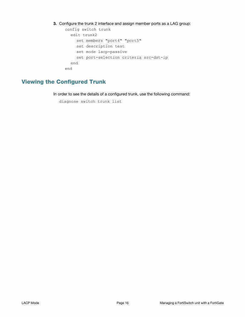
3. Configure the trunk 2 interface and assign member ports as a LAG group:
config switch trunkedit trunk2
set members "port4" "port5"set description testset mode lacp-passiveset port-selection criteria src-dst-ip
endend
Viewing the Configured Trunk
In order to see the details of a configured trunk, use the following command:
diagnose switch trunk list
LACP Mode Page 16 Managing a FortiSwitch unit with a FortiGate

TACACS
This chapter contains information on using TACACS authetication with your FortiSwitch unit.
Administrative Accounts
Administrative, or admin, accounts allow access to various aspects of the FortiSwitch
configuration. The level of access is determined by the access profile used in the admin
account.
Configuring an Access Profile for Admin Accounts
Using the web-based manager:
1. Go to System > Admin > Admin Profile and select Create New.
2. Give the profile an appropriate name.
3. Set Access Control as desired, choosing between None, Read Only, or Read-Write.
4. Select OK.
Using the CLI:
config system accprofileedit <name>
set admingrp {none | read | read-write}set loggrp {none | read | read-write}set netgrp {none | read | read-write}set routegrp {none | read | read-write}set sysgrp {none | read | read-write}
endend
Configuring a TACACS Admin Account
Using the web-based manager:
1. Go to System > Admin > Administrators and select Create New.
2. Give the administrator account an appropriate name.
3. Set Type as Remote.
4. Set User Group to a group for remote users.
5. Enable Wildcard.
6. Set Admin Profile to use the new profile.
7. Select OK.
Page 17

Using the CLI:
config system adminedit tacuser
set remote-auth enableset wildcard enableset remote-group <group>set accprofile <profile>
endend
User Accounts
User accounts can be used to identify a network user and determine what parts of the network
the user is allowed to access.
Configuring a User Account
config user tacacs+edit <tacserver>
set authen-type {ascii | auto | chap | ms_chap | pap}set authorization enableset key <authorization_key>set server <server>
endend
Configuring a User Group
config user groupedit <tacgroup>
set member <tacserver>config match
edit 1set server-name <server>set group-name <group>
endend
endend
Example Configuration
The following is an example configuration of a TACACS user account, with the CLI syntax
shown to create it:
TACACS Page 18 Managing a FortiSwitch unit with a FortiGate

1. Configuring a TACACS user account for login authentication:
config user tacacs+edit tacserverset authen-type ascii set authorization enableset key temporaryset server tacacs_server
end2. Configuring a TACACS user group:
config user groupedit tacgroup
set member tacserverconfig match
edit 1set server-name tacserverset group-name tacgroup
endend
endend
3. Configuring a TACACs system admin user account:
config system adminedit tacuser
set remote-auth enableset wildcard enableset remote-group tacgroupset accprofile noaccess
endend
TACACS Page 19 Managing a FortiSwitch unit with a FortiGate

Power over Ethernet
This chapter contains information on using Power over Ethernet (PoE) with your FortiSwitch.
Power over Ethernet is only available on the following models: FortiSwitch-108D-POE,
FortiSwitch-124D-POE, FortiSwitch-224D-POE, and FortiSwitch-324B-POE.
Enabling PoE on a Port
config switch physical-portedit <port>
set poe-status enableend
end
Determining the PoE Power Capacity
To determine the PoE power capacity, use the following command:
get switch poe inline
Reset the PoE Power on a Port
To reset the PoE power on a port, use the following command:
execute poe-reset <port>
Page 20