FORTiS-N™ FS enclosed encoder system Functional Safety ...
38
FORTiS-N ™ enclosed encoder system Functional Safety installation guide and safety manual Installation guide M-6725-9026-01-D
Transcript of FORTiS-N™ FS enclosed encoder system Functional Safety ...

RSLM high accuracy linear encoder FORTiS-N™ enclosed encoder systemFunctional Safety installation guide and safety manual
Installation guideM-6725-9026-01-D

ii Original instructions
1 Legal notices 11.1 Copyright 11.2 Trade marks 11.3 Patents 11.4 Disclaimer 11.5 Terms and Conditions and Warranty 11.6 Declaration of Conformity 11.7 Product compliance 11.8 Compliance 11.9 Intended use 21.10 Warnings 21.11 Further information 21.12 Packaging 21.13 REACH regulation 21.14 WEEE recycling guidelines 2
2 Definitions 3
3 Information for use 3
4 Functional Safety data declaration 4
5 Safety function 55.1 Fault exclusions 55.2 Failure modes effects and diagnostics analysis 55.3 Installation 55.4 Commissioning test 55.5 Evaluation unit monitoring 55.6 Maintenance 55.7 Repair 55.8 Proof testing 5
6 Certification 6
7 Summary of EU declaration of conformity 6
8 Overview of the FORTiS-N FS encoder system 7
9 Parts list 89.1 Included in the box 89.2 Not included / required tools 89.3 Optional extras 9
9.3.1 Mounting aid 99.3.2 Mounting spar 9
9.4 Cable options 99.4.1 FORTiS-N FS connector 9
Contents10 Storage and handling 10
11 Installation drawings 1111.1 Mounting surface preparation 1111.2 Datum location edge or dowel pins – standard end caps 1111.3 Mounting orientations – standard end caps 1211.4 Mounting orientations – short end caps 1211.5 FORTiS-N FS system installation drawing – standard end caps 1311.6 FORTiS-N FS system installation drawing – short end caps 14
12 Productspecification 15
13 Installation procedure – extrusion 1613.1 Protection for sealed linear encoders 1613.2 Thermal datum 1613.3 Extrusion installation without mounting spar 1713.4 Installation with mounting spar 1813.5 Mounting spar installation drawing 1913.6 Spar mounting options 20
14 Installation procedure – readhead 2114.1 Start of measuring length – standard 2114.2 Start of measuring length – short end caps 2114.3 Alignment bracket method 22
14.3.1 Installation using the alignment bracket method 2314.4 Set-up shim method 24
14.4.1 Front setting shim procedure 2414.4.2 Side setting shim procedure 25
14.5 Installation using the mounting aid method 2614.6 FORTiS-N FS cable connection 2814.7 Validating an installation 2914.8 Air supply 30
15 Cables and serial interfaces 3115.1 Generalspecifications 3115.2 Permissible cable lengths 3115.3 BiSS Safety serial interface 3215.4 Siemens DRIVE-CLiQ serial interface 34
15.4.1 Siemens DRIVE-CLiQ serial interface 35

1Original instructions
1 Legal notices1.1 Copyright© 2020-2021 Renishaw plc. All rights reserved.
This document may not be copied or reproduced in whole or in part, or transferred to any other media or language by any means, without the prior written permission of Renishaw.
1.2 Trade marksRENISHAW® and the probe symbol are registered trade marks of Renishaw plc. Renishaw product names, designations and the mark “apply innovation” are trade marks of Renishaw plc or its subsidiaries. Other brand, product or company names are trade marks of their respective owners.
BiSS ® is a registered trade mark of iC-Haus GmbH.
1.3 PatentsFeatures of Renishaw’s encoder systems and similar products are the subjects of the following patents and patent applications:
1.4 DisclaimerWHILE CONSIDERABLE EFFORT WAS MADE TO VERIFY THE ACCURACY OF THIS DOCUMENT AT PUBLICATION, ALL WARRANTIES, CONDITIONS, REPRESENTATIONS AND LIABILITY, HOWSOEVER ARISING, ARE EXCLUDED TO THE EXTENT PERMITTED BY LAW.
RENISHAW RESERVES THE RIGHT TO MAKE CHANGES TO THIS DOCUMENT AND TO THE EQUIPMENT, AND/OR SOFTWARE AND THE SPECIFICATION DESCRIBED HEREIN WITHOUT OBLIGATION TO PROVIDE NOTICE OF SUCH CHANGES.
1.5 Terms and Conditions and WarrantyUnless you and Renishaw have agreed and signed a separate written agreement, the equipment and/or software are sold subject to the Renishaw Standard Terms and Conditions supplied with such equipment and/orsoftware,oravailableonrequestfromyourlocalRenishawoffice.
Renishaw warrants its equipment and software for a limited period (as set out in the Standard Terms andConditions),providedthattheyareinstalledandusedexactlyasdefinedinassociatedRenishawdocumentation.YoushouldconsulttheseStandardTermsandConditionstofindoutthefulldetailsofyourwarranty.
Equipment and/or software purchased by you from a third-party supplier is subject to separate terms and conditions supplied with such equipment and/or software. You should contact your third-party supplier for details.
CN1260551 US7499827 JP4008356 GB2395005 US20100163536
US20150225858 CN102197282 EP2350570 JP5480284 US8505210
KR1630471 CN102388295 EP2417423 KR1701535 US2012007980
CN102460077 EP2438402 US20120072169 KR1851015 JP6074392
JP5755223 EP01103791 US6465773
1.6 Declaration of ConformityRenishaw plc hereby declares that the FORTiS-N™ enclosed encoder system is in compliance with the essential requirements and other relevant provisions of:
X the applicable EU directives
X the relevant statutory instruments under UK law
The full text of the Declaration of Conformity is available at: www.renishaw.com/productcompliance
1.7 Product complianceThis document is an installation guide and safety manual which details the actions required for the safe integration of the FORTiS-N FS encoder system with BiSS Safety or Siemens DRIVE-CLiQ protocols, as designated by the letter S in this location in the part number, e.g. FN100A012HC28DS050X, into a functionally safe system.
The FORTiS-N FS encoder system is suitable for use in a Category 3 performance level d (PLd) applicationincompliancewithISO 13849‑1andinasafetyintegritylevel2(SIL2)applicationincompliancewithIEC 61508‑1andIEC 61800‑5‑2wheninstalledandoperatedinaccordancewiththeinstructionsdefined.FailuretofollowthecorrectuseinstructionsandfailuretoheedthelimitationsmayresultinSIL2and/orPLdnotbeingachievedandwillinvalidatetheFunctionalSafetycertification.
AcopyoftheFORTiS‑NFSencodersystemcertificateisavailablefromourwebsiteatwww.renishaw.com/productcompliance
1.8 ComplianceFederal Code Of Regulation (CFR) FCC Part 15 – RADIO FREQUENCY DEVICES47 CFR Section 15.19
This device complies with part 15 of the FCC Rules. Operation is subject to the following two conditions:
(1) This device may not cause harmful interference, and (2) this device must accept any interference received, including interference that may cause undesired operation.
47 CFR Section 15.21
TheuseriscautionedthatanychangesormodificationsnotexpresslyapprovedbyRenishawplcorauthorised representative could void the user’s authority to operate the equipment.
47 CFR Section 15.105
This equipment has been tested and found to comply with the limits for a Class A digital device, pursuant to part 15 of the FCC Rules. These limits are designed to provide reasonable protection against harmful
SIL2FUNCTIONAL
SAFETY
PLd

2 Original instructions
interference when the equipment is operated in a commercial environment. This equipment generates, uses, and can radiate radio frequency energy and, if not installed and used in accordance with the instruction manual, may cause harmful interference to radio communications. Operation of this equipment in a residential area is likely to cause harmful interference in which case the user will be required to correct the interference at their own expense.
47 CFR Section 15.27
This unit was tested with shielded cables on the peripheral devices. Shielded cables must be used with the unit to ensure compliance.
ICES-001—Industrial,ScientificandMedical(ISM)Equipment(Canada)
This ISM device complies with Canadian ICES-001.
Cet appareil ISM est conforme à la norme ICES-001 du Canada.
1.9 Intended useThe FORTiS enclosed encoder system is designed for metrology in industrial environments, such as machinetools.Itmustbeinstalled,operated,andmaintainedasspecifiedinRenishawdocumentationand in accordance to the Standard Terms and Conditions of the Warranty and all other relevant legal requirements.
1.10 WarningsIn all applications involving the use of machine tools eye protection is recommended.
1.11 Further informationFurther information relating to the FORTiS encoder range can be found in the FORTiS data sheets available from your local Renishaw representative or from our website: www.renishaw.com/fortisdownloadsSee also the data sheet Cables for FORTiS absolute encoders (Renishaw part no. L-9517-0069).
Packaging component Material ISO 11469 Description
Wooden box Plywood and softwood Not applicable Recyclable
Outer box Cardboard Not applicable Recyclable
Polypropylene PP Recyclable
Inserts Low density polyethylene foam
LDPERecyclable
Cardboard Not applicable Recyclable
Bags High density polyethylene bag
HDPERecyclable
Metalised polyethylene PE Recyclable
1.12 PackagingThe packaging of our products contains the following materials and can be recycled.
1.13 REACH regulationInformation required by Article 33(1) of Regulation (EC) No. 1907/2006 (“REACH”) relating to products containing substances of very high concern (SVHCs) is available at www.renishaw.com/REACH
1.14 WEEE recycling guidelinesThe use of this symbol on Renishaw products and/or accompanying documentation indicates that the product should not be mixed with general household waste upon disposal. It is the responsibility of the end user to dispose of this product at a designated collection point for waste electrical and electronic equipment (WEEE) to enable reuse or recycling. Correct disposal of this product will help to save valuable resources and prevent potential negative effects on the environment. For more information, please contact your local waste disposal service or Renishaw distributor.
3Original instructions
2 Definitions
WARNING A hazard with a medium risk of injury if not avoided
ESD handling The ESD Susceptibility Symbol consists of a triangle, a reaching hand, and a slash through the reaching hand. The triangle means “Caution” and the slash through the reaching hand means “Don’t touch”.
Mechanicalsafeposition The maximum distance the scale might move from its installed position,forexampleifthefixingsworkloose.
Evaluation unit External item of equipment in which the output signal of the encoder is evaluated, e.g. machine controller or safety relay.
System manufacturer Personnel with responsibility for selecting the encoder and verifying its capability is appropriate for the safety-related application.
System installer Personnelwithresponsibilityforfittingtheencoderinthespecificapplication.
WARNING Not to be used in environments where there is an explosive atmosphere
WARNING Not to be used by medical devices
The FORTiS-N FS encoder system is designed to be used as part of a safety-related control system asspecifiedbythesystemmanufacturer.Itistheresponsibilityofthesystemmanufacturertosettheevaluation unit to implement the appropriate actions when the FORTiS-N FS encoder system reports an error. The decision to use this system for the intended purpose is the responsibility of the system manufacturer.TheFORTiS‑NFSencodersystemiscertifiedtotheSILandPLlevelsasshowninthe“Functional Safety data declaration” table; however, the system manufacturer must conduct their own assessment of the full system to determine its safety capability.
Correct use includes:
X Operating the FORTiS-N FS encodersystemwithinthelimitsdefinedinthisdocument.
X Installing the system as described in this document.
X Maintaining the system as described in this document.
System components covered by this installation guide:
The FORTiS-N FS encoder system comprises the following parts:
X FORTiS-N FS encoder unit.
X Accessories.
X Cable.
X Extension cable (when required).
X DRIVE-CLiQ interface (when required).
NOTE: If the original termination supplied with the FORTiS-N FS encoder system is altered or a non-Renishaw cable that is not approved is used, then it is the responsibility of the system manufacturer tomakesurethesystemiscompliantwithIEC 61800‑5‑2:2016Electromagnetic immunity requirement for safety related systems – Annex E, second environment.
3 Information for use
4 Original instructions
4 Functional Safety data declaration
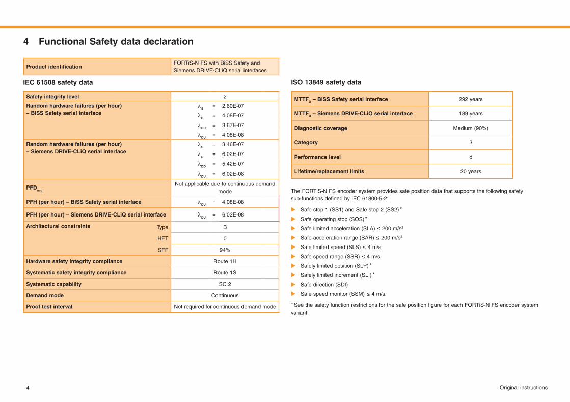
ProductidentificationFORTiS-N FS with BiSS Safety and Siemens DRIVE-CLiQ serial interfaces
MTTFD – BiSS Safety serial interface 292 years
MTTFD – Siemens DRIVE-CLiQ serial interface 189 years
Diagnostic coverage Medium (90%)
Category 3
Performance level d
Lifetime/replacement limits 20 years
Safety integrity level 2
Random hardware failures (per hour) – BiSS Safety serial interface
lS= 2.60E-07
lD= 4.08E-07
lDD= 3.67E-07
lDU= 4.08E-08
Random hardware failures (per hour) – Siemens DRIVE-CLiQ serial interface
lS= 3.46E-07
lD= 6.02E-07
lDD= 5.42E-07
lDU= 6.02E-08
PFDavg
Not applicable due to continuous demand mode
PFH (per hour) – BiSS Safety serial interface lDU= 4.08E-08
PFH (per hour) – Siemens DRIVE-CLiQ serial interface lDU= 6.02E-08
Architectural constraints Type B
HFT 0
SFF 94%
Hardware safety integrity compliance Route 1H
Systematic safety integrity compliance Route 1S
Systematic capability SC 2
Demand mode Continuous
Proof test interval Not required for continuous demand mode
IEC 61508safetydata ISO 13849safetydata
The FORTiS-N FS encoder system provides safe position data that supports the following safety sub‑functionsdefinedbyIEC61800‑5‑2:
X Safe stop 1 (SS1) and Safe stop 2 (SS2) *
X Safe operating stop (SOS) *
X Safelimitedacceleration(SLA)≤ 200m/s2
X Safeaccelerationrange(SAR)≤ 200m/s2
X Safelimitedspeed(SLS)≤ 4m/s
X Safespeedrange(SSR)≤ 4m/s
X Safely limited position (SLP) *
X Safely limited increment (SLI) *
X Safe direction (SDI)
X Safespeedmonitor(SSM)≤ 4m/s.
*SeethesafetyfunctionrestrictionsforthesafepositionfigureforeachFORTiS‑NFSencodersystemvariant.

5Original instructions
5 Safety functionTheFORTiS-NFSencodersystemshallprovideasafepositionwhenrequestedbytheevaluationunit.
The following restrictions apply to this claim:
X Thesysteminstallermustperformaverifiedcommissioningtestduringinstallation.
X Thesystemrepairermustperformaverifiedcommissioningtestfollowingreplacementofasystempart.
X Themaximumrequestratesupportedis32 kHz.
X Electrical errors for the BiSS Safety serial interface are detected by the evaluation unit comparing CPW and SPW content. See BiSS Safety for RESOLUTE encoders data sheet (Renishaw part no. L-9517-9884) for more information.
X Electrical errors for the Siemens DRIVE-CLiQ serial interface are detected by the evaluation unit comparing POS1 and POS2 content. See the relevant Siemens AG evaluation unit manual for more information.
X When installed correctly, the FORTiS-N FS encoder without mounting spar has a mechanical safe positionof±1 mm.Wheninstalledcorrectly,theFORTiS‑NFSencoderwith mounting spar has a mechanicalsafepositionof±4 mm.
5.1 Fault exclusionsThefollowingwillinvalidatetheFunctionalSafetycertificationoftheFORTiS-N FS encoder system:
X Faults caused by cutting and reconnecting the cable or the use of a non-Renishaw cable that is not approved.
X Incorrect installation.
X Dismantling.
X Operatingthesystemoutsideofthelimitsspecifiedinthisinstallationguide.
5.2 Failure modes effects and diagnostics analysisAll diagnosed failure modes are detected immediately except for a position discrepancy between the two measurementmethodswhichisdetectedwithin375 μs.
See “Functional Safety data declaration” on page 4 for a summary of the FMEDA.
NOTE: For the purposes of the FMEDA calculation the following conditions have been assumed:
Method: SN29500-2005-1 Environment: Ground mobile Temperature: 60 °C
5.3 InstallationFor the safety function to be valid the instructions detailed in this installation guide must be followed.
5.4 Commissioning testThe following test MUST be performed when commissioning the FORTiS-N FS encoder system and after any repair or maintenance of the system.
Resolution check Movetheaxisbyaknowndistanceandconfirmthatthepositionchangesas expected. The tolerance for raising a fault condition is relative to the safe position determined by the system manufacturer.
5.5 Evaluation unit monitoringTo achieve full system integrity the evaluation unit must continuously monitor the error condition of the FORTiS-N FS encoder system, and in the case of fault detection place the system into a safe state within the process safety time.
NOTES:
X TheevaluationunitmusthaveitsFunctionalSafetyfunctionsenabled(asoftenitisaconfigurationparametertoturnonFunctionalSafetyfunctionality)andmustrespondcorrectlytoaFORTiS‑N FSencodersystempositionerrorflag.
X A persistent fault condition may indicate a hardware failure of the FORTiS-N FS encoder system or an installation problem.
5.6 MaintenanceThemaintenancecheckintervalswillbedefinedbythesystemmanufactureraccordingtotheirriskassessment. There are no user-serviceable parts within the FORTiS-N FS encoder system.
The following maintenance actions are advised:
X Check the extrusion screws and readhead retaining screws are correctly tightened.
X Check for worn or damaged cables and connectors.
X Check the cable connectors and air line connection are correctly tightened/located.
X Checktheairsupplyfittingiscorrectlytightenedandtheairhoseiscorrectlyfitted.
X When the DRIVE-CLiQ interface is used check the retaining screws are correctly tightened.
X Check the extrusion end cap screws and readhead retaining screws are correctly tightened.
5.7 Repair X Repair of the FORTiS-N FS encoder system is only by replacement of parts.
X The replacement parts must have the same part number as the original parts.
X The repaired encoder system must be installed and commissioned in accordance with the “Commissioning test” above.
X In the event of failure the affected parts should be returned to Renishaw for further analysis.
X UsingdamagedpartsinvalidatestheFunctionalSafetycertification.
5.8 Proof testingItistheresponsibilityofthesystemmanufacturertodefineanyprooftestingofthesystem.Duetothediagnostic coverage (DC) and safe failure fraction (SFF) required to achieve SIL2, the encoder can only support continuous demand use.

6 Original instructions
Renishawplcdeclaresunderitssoleresponsibilitythattheproductsidentifiedbelowareinconformitywithall relevant Union legislation:
Product Name: FORTiS-N™ series FS encoder system
Description: FORTiS-N™FSencodersystemthatisfunctionalsafetycertified
Part no.: FN1*-02, e.g. FN100B044SC36BS050X-02
Valid from: Mod level -02
The product complies with EU directives:
The product complies with the following technical standards:
2006/42/EC Machinery directive
2014/30/EU Electromagnetic compatibility (EMC)
2011/65/EU Ontherestrictionoftheuseofcertainhazardoussubstancesinelectrical and electronic equipment (recast)
EN 12100:2010 Safety of machinery – General principles for design –Risk assessment and risk reduction
EN 61326-1:2013 Electrical equipment for measurement, control, and laboratory use. Part 1: General requirementsImmunity to Table 2 – Industrial electromagnetic environmentEmissions to Class A – Industrial electromagnetic environment
EN 13849-1:2015 Safety of machinery – Safety-related parts of control systems Part 1: General principles for design
EN 13849-2:2012 Safety of machinery – Safety-related parts of control systems Part 2: Validation
EN 62471:2008 Photobiological safety of lamps and lamp systems
EN 63000:2018 Technical documentation for the assessment of electrical and electronicproductswithrespecttotherestrictionofhazardoussubstances
7 Summary of EU declaration of conformityEUD2020-00526
For the full declaration of conformity EUD2020-00526 see www.renishaw.com/productcompliance
6 Certification
UnderthetermsofCSASIRAFunctionalSafetyCertificateSIRACASS00023/01, for the management andself‑certificationoffunctionalsafetyactivitiesuptoSIL3/PLd:
Renishaw plc declares that the products listed by this installation guide meet the requirements of:
IEC 61508-1:2010, IEC 61508-2:2010 and IEC 61508-3:2010
IEC 61800-5-2:2016
ISO 13849-1:2015 and ISO 13849-2:2012
when used as an element/subsystem in safety-related systems performing safety functions requiring up to and including:
SIL2 with HFT = 0 (1oo1)
Category 3, PLd.
FORTiS-N FS encoder system
FunctionalSafetyCertificateNo.FSC003
SIL2FUNCTIONAL
SAFETY
PLd

7Original instructions
8 Overview of the FORTiS-N FS encoder systemThis system is an enclosed linear optical encoder designed for use in harsh industrial environments where high-precision feedback and metrology are required. Based upon Renishaw’s award-winning absolute technology, the rugged non-contact design has no internal moving parts, such as bearings or wheeled readhead carriages, thus improving the overall reliability. Additionally, hysteresis and backlash errors associated with mechanical contact system designs are reduced.
Inadditiontoenhancedbreakageresistance,therobuststeelscalehasacoefficientofthermalexpansionsimilar to the base material used in the majority of machines, reducing errors due to thermal effects whilst increasing measurement certainty.
Renishaw’spatentedset‑upLEDprovidesinstantverificationoftheencoder’ssignalstrengthandtherefore its accurate alignment. This intuitive procedure eliminates the need for additional peripheral diagnostics equipment during installation. When combined with Renishaw’s carefully designed installation accessories, these unique tools make installation easier and faster compared to traditional methods, whilst buildingconfidenceinaright‑first‑timeinstallation.
8 Original instructions
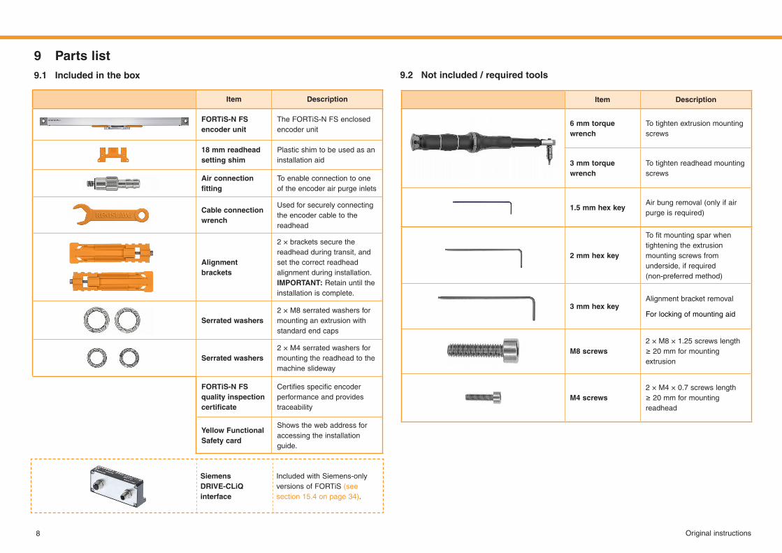
9 Parts list9.1 Included in the box 9.2 Notincluded/requiredtools
Item Description
6mmtorquewrench
To tighten extrusion mounting screws
3mmtorquewrench
To tighten readhead mounting screws
1.5 mm hex keyAir bung removal (only if air purge is required)
2 mm hex key
Tofitmountingsparwhentightening the extrusionmounting screws fromunderside, if required (non-preferred method)
3 mm hex keyAlignment bracket removal
For locking of mounting aid
M8screws2 × M8 × 1.25 screws length ≥ 20 mmformountingextrusion
M4screws2 × M4 × 0.7 screws length ≥ 20 mmformountingreadhead
Item Description
FORTiS-N FS encoder unit
The FORTiS-N FS enclosed encoder unit
18 mm readhead setting shim
Plastic shim to be used as an installation aid
Air connection fitting
To enable connection to one of the encoder air purge inlets
Cable connection wrench
Used for securely connecting the encoder cable to the readhead
Alignment brackets
2 × brackets secure the readhead during transit, and set the correct readhead alignment during installation. IMPORTANT: Retain until the installation is complete.
Serrated washers2 × M8 serrated washers for mounting an extrusion with standard end caps
Serrated washers 2 × M4 serrated washers for mounting the readhead to the machine slideway
FORTiS-N FS qualityinspectioncertificate
Certifiesspecificencoderperformance and provides traceability
Yellow Functional Safety card
Shows the web address for accessing the installation guide.
Siemens DRIVE-CLiQ interface
Included with Siemens-only versions of FORTiS (see section 15.4 on page 34).
9Original instructions
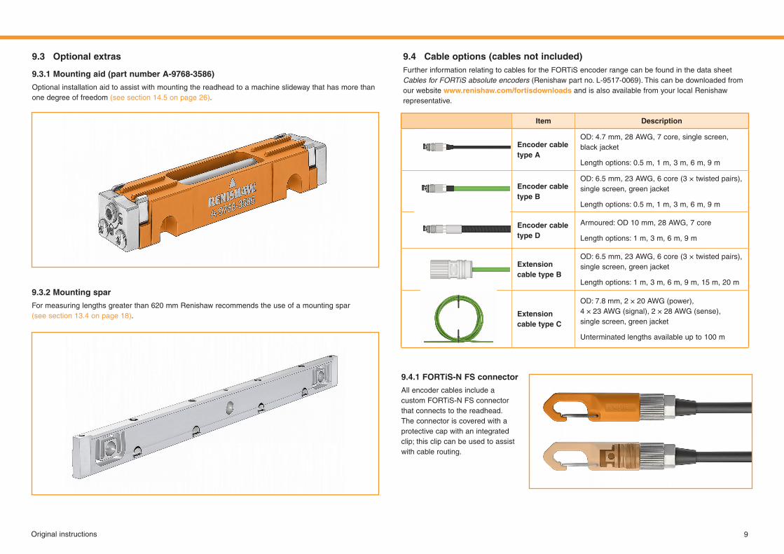
9.3 Optional extras 9.4 Cable optionsFurther information relating to cables for the FORTiS encoder range can be found in the data sheet Cables for FORTiS absolute encoders (Renishaw part no. L-9517-0069). This can be downloaded from our website www.renishaw.com/fortisdownloads and is also available from your local Renishaw representative.
9.3.1 Mountingaid
Optional installation aid to assist with mounting the readhead to a machine slideway that has more than one degree of freedom (see section 14.5 on page 26).
9.3.2 Mountingspar
For measuring lengths greater than 620 mm Renishaw recommends the use of a mounting spar (see section 13.4 on page 18).
9.4.1 FORTiS-N FS connector
All encoder cables include a custom FORTiS-N FS connector that connects to the readhead. The connector is covered with a protective cap with an integrated clip; this clip can be used to assist with cable routing.
Item Description
Encoder cable type A
OD: 4.7 mm, 28 AWG, 7 core, single screen, black jacket
Length options: 0.5 m, 1 m, 3 m, 6 m, 9 m
Encoder cable type B
OD: 6.5 mm, 23 AWG, 6 core (3 × twisted pairs), single screen, green jacket
Length options: 0.5 m, 1 m, 3 m, 6 m, 9 m
Encoder cable type D
Armoured: OD 10 mm, 28 AWG, 7 core
Length options: 1 m, 3 m, 6 m, 9 m
Extension cable type B
OD: 6.5 mm, 23 AWG, 6 core (3 × twisted pairs), single screen, green jacket
Length options: 1 m, 3 m, 6 m, 9 m, 15 m, 20 m
Extension cable type C
OD: 7.8 mm, 2 × 20 AWG (power), 4 × 23 AWG (signal), 2 × 28 AWG (sense), single screen, green jacket
Unterminated lengths available up to 100 m
(part number A-9768-3586)
(cables not included)
10 Original instructions
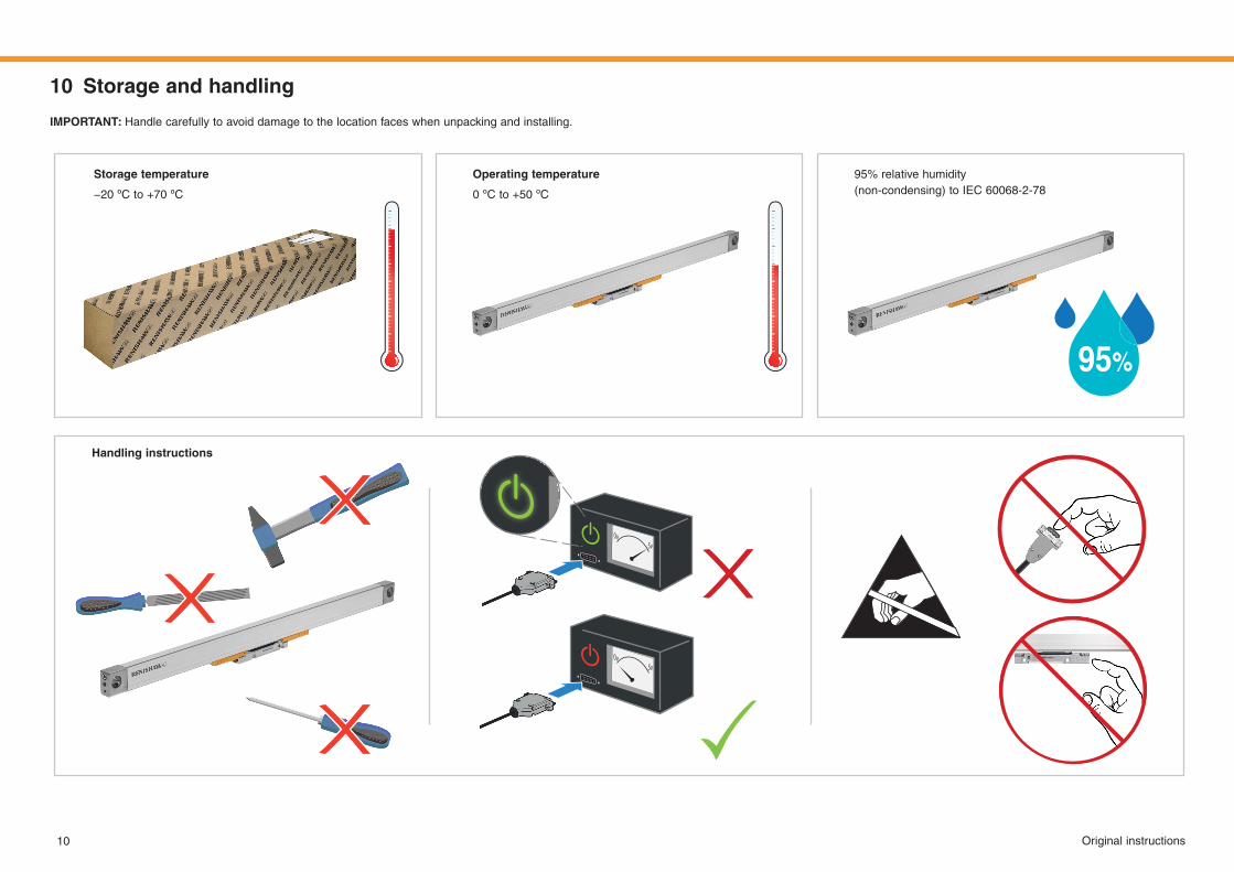
10 Storage and handling
95% relative humidity (non‑condensing)toIEC 60068‑2‑78
Handling instructions
Storage temperature
−20ºCto+70ºC
Operating temperature
0ºCto+50ºC
IMPORTANT:Handle carefully to avoid damage to the location faces when unpacking and installing.
11Original instructions
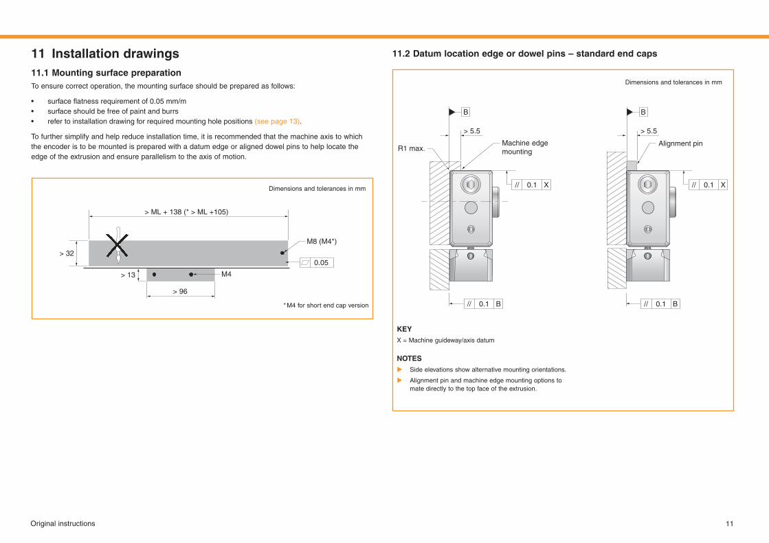
11 Installation drawings11.1 MountingsurfacepreparationTo ensure correct operation, the mounting surface should be prepared as follows:
• surfaceflatnessrequirementof0.05mm/m• surface should be free of paint and burrs• refer to installation drawing for required mounting hole positions (see page 13).
To further simplify and help reduce installation time, it is recommended that the machine axis to which the encoder is to be mounted is prepared with a datum edge or aligned dowel pins to help locate the edge of the extrusion and ensure parallelism to the axis of motion.
11.2 Datum location edge or dowel pins – standard end caps
Dimensions and tolerances in mm
* M4 for short end cap version
> 32
> 13
> 96
M4
0.05
M8 (M4*)
>ML+138(* > ML+105)
KEYX = Machine guideway/axis datum
NOTES X Side elevations show alternative mounting orientations.
X Alignment pin and machine edge mounting options to mate directly to the top face of the extrusion.
Dimensions and tolerances in mm
> 5.5 > 5.5
R1 max. Machine edge mounting
B B
// //
// //
X X
B B
0.1 0.1
0.1 0.1
Alignment pin
12 Original instructions
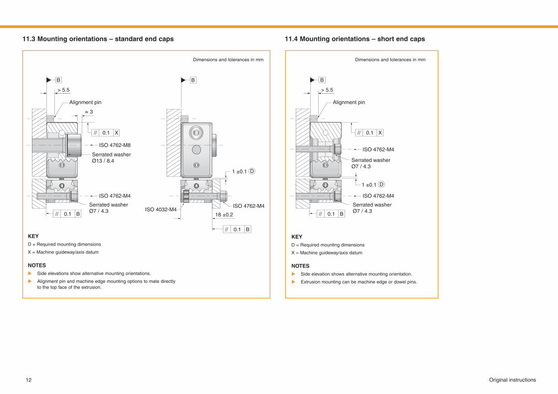
11.3 Mountingorientations–standardendcaps 11.4 Mountingorientations–shortendcaps
KEYD = Required mounting dimensions
X = Machine guideway/axis datum
NOTES X Side elevations show alternative mounting orientations.
X Alignment pin and machine edge mounting options to mate directly to the top face of the extrusion.
Dimensions and tolerances in mm
> 5.5
≈3
Alignment pin
ISO 4762-M8
ISO 4762-M4ISO 4032-M4
1 ±0.1
18 ±0.2
ISO 4762-M4
Serrated washerØ13 / 8.4
Serrated washerØ7 / 4.3
B B
//
//
//
B
B
X
0.1
0.1
0.1
KEYD = Required mounting dimensions
X = Machine guideway/axis datum
NOTES X Side elevation shows alternative mounting orientation.
X Extrusion mounting can be machine edge or dowel pins.
Dimensions and tolerances in mm
> 5.5
Alignment pin
ISO 4762-M4
ISO 4762-M4
Serrated washerØ7 / 4.3
Serrated washerØ7 / 4.3
B
//
//
B
X
0.1
0.1
D
D1 ±0.1
13Original instructions
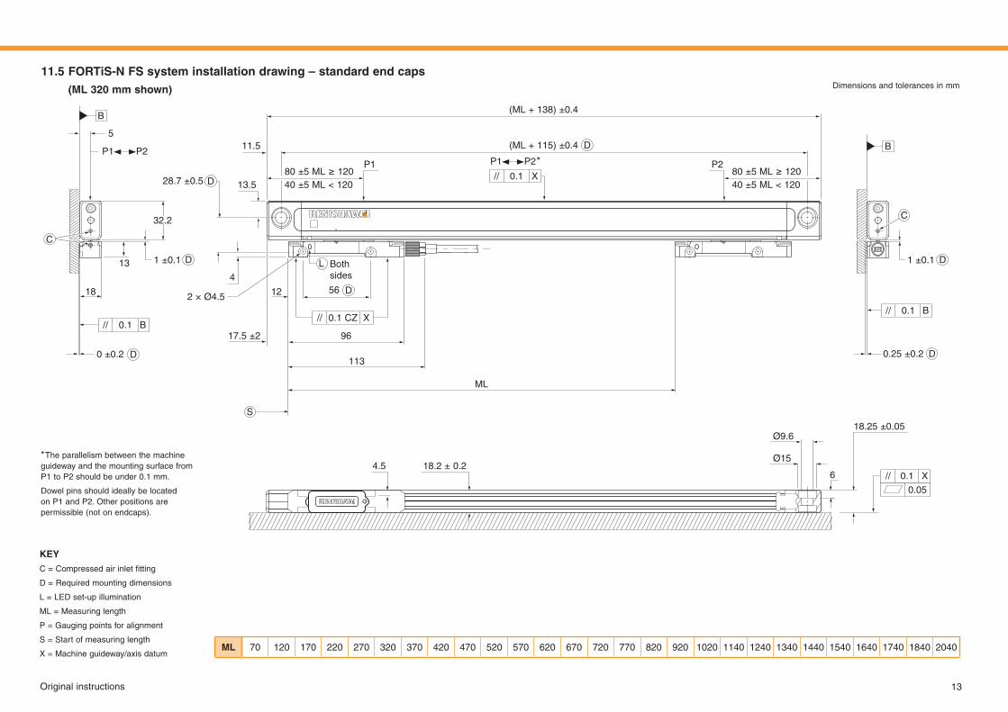
11.5 FORTiS-N FS system installation drawing – standard end caps(ML320 mmshown) Dimensions and tolerances in mm
KEYC=Compressedairinletfitting
D = Required mounting dimensions
L = LED set-up illumination
ML = Measuring length
P = Gauging points for alignment
S = Start of measuring length
X = Machine guideway/axis datum
B
S
D
C
5
P1 P2 *P1 P2
11.5
P1 P2
13.5
4
12 56
17.5 ±2 96
113
ML
28.7 ±0.580±5ML≥12040 ±5 ML < 120
80±5ML≥12040 ±5 ML < 120
(ML+ 138)±0.4
(ML+ 115)±0.4
13
32.2
18
//
//
//
//
//B
B
X
X
X0.1
0.1
0.1
0.1
0.1 CZ
1 ±0.1 1 ±0.1
0.25 ±0.2
Both sides
2 × Ø4.5
Ø9.6
4.5 18.2 ± 0.2Ø15
6
18.25 ±0.05
0.05
0 ±0.2
D
D
L
D
D
B
C
ML 70 120 170 220 270 320 370 420 470 520 570 620 670 720 770 820 920 1020 1140 1240 1340 1440 1540 1640 1740 1840 2040
D
D
* The parallelism between the machine guideway and the mounting surface from P1toP2shouldbeunder0.1 mm.
Dowel pins should ideally be located on P1 and P2. Other positions are permissible (not on endcaps).
14 Original instructions
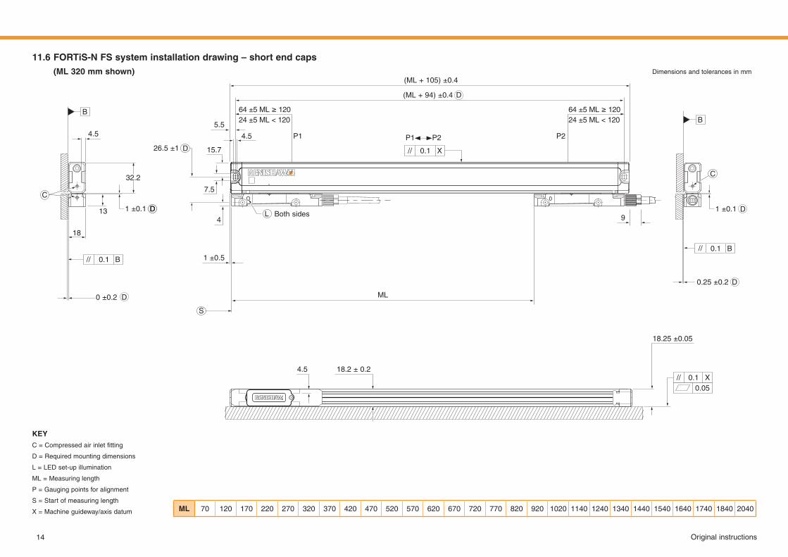
11.6 FORTiS-N FS system installation drawing – short end caps(ML320 mmshown) Dimensions and tolerances in mm
B
DD
D
D
D
D
C
4.5
Both sides
5.5
15.7
7.5
4.5 P1 P2
4 9
26.5 ±1
(ML+ 105)±0.4
(ML+ 94)±0.4D
13
32.2
18
//
//
//
B
B
X
0.1
0.1
0.050.1
1 ±0.1
1 ±0.5
1 ±0.1
0.25 ±0.2
4.5 18.2 ± 0.2
18.25 ±0.05
0 ±0.2
B
C
KEYC=Compressedairinletfitting
D = Required mounting dimensions
L = LED set-up illumination
ML = Measuring length
P = Gauging points for alignment
S = Start of measuring length
X = Machine guideway/axis datum
S
ML
L
ML 70 120 170 220 270 320 370 420 470 520 570 620 670 720 770 820 920 1020 1140 1240 1340 1440 1540 1640 1740 1840 2040
64±5ML≥12024 ±5 ML < 120
64±5ML≥12024 ±5 ML < 120
// X0.1
P1 P2
15Original instructions
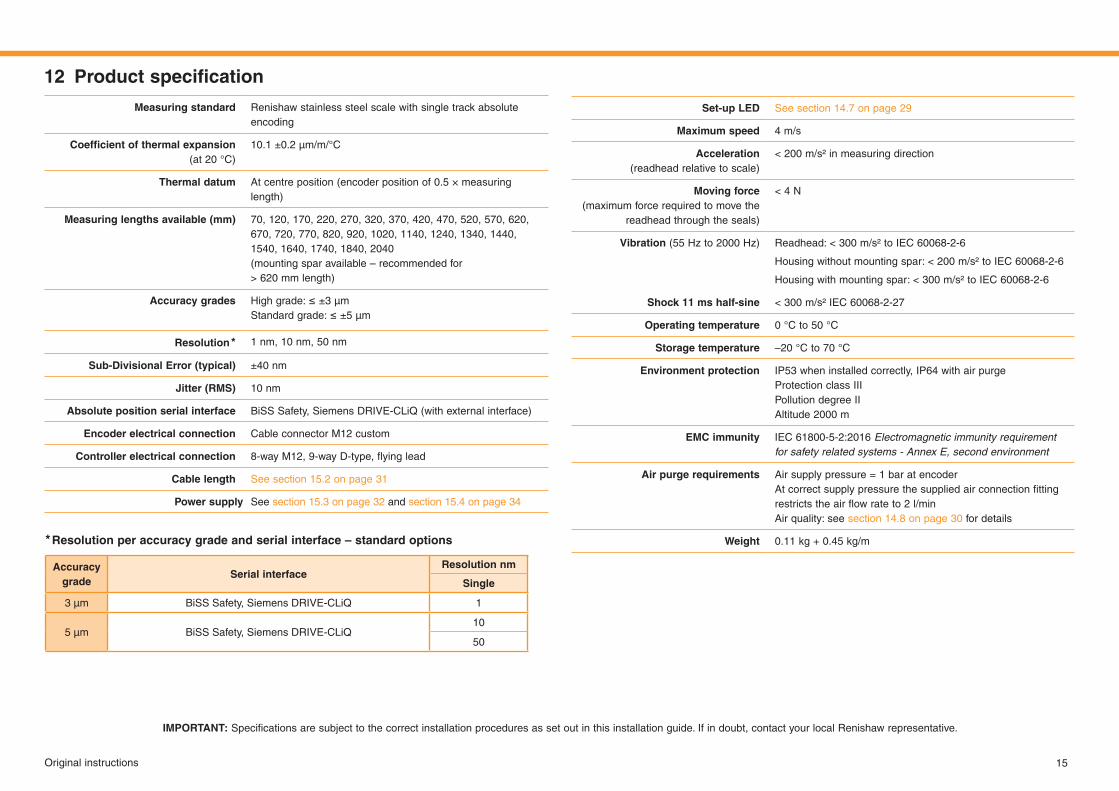
12 Productspecification
Set-up LED See section 14.7 on page 29
Maximumspeed 4 m/s
Acceleration (readhead relative to scale)
< 200m/s²inmeasuringdirection
Movingforce(maximum force required to move the
readhead through the seals)
< 4N
Vibration (55Hzto2000Hz) Readhead:<300 m/s²toIEC 60068‑2‑6
Housingwithoutmountingspar:< 200 m/s²toIEC 60068‑2‑6
Housingwithmountingspar:< 300 m/s²toIEC 60068‑2‑6
Shock 11 ms half-sine < 300m/s²IEC 60068‑2‑27
Operating temperature 0 °Cto50 °C
Storage temperature –20 °Cto70 °C
Environment protection IP53 when installed correctly, IP64 with air purge Protection class IIIPollution degree IIAltitude2000 m
EMCimmunity IEC 61800-5-2:2016 Electromagnetic immunity requirement for safety related systems - Annex E, second environment
Airpurgerequirements Air supply pressure = 1 bar at encoderAtcorrectsupplypressurethesuppliedairconnectionfittingrestrictstheairflowrateto2 l/minAir quality: see section 14.8 on page 30 for details
Weight 0.11kg+0.45kg/m
Measuringstandard Renishaw stainless steel scale with single track absolute encoding
Coefficientofthermalexpansion (at20°C)
10.1±0.2μm/m/°C
Thermal datum At centre position (encoder position of 0.5 × measuring length)
Measuringlengthsavailable(mm) 70, 120, 170, 220, 270, 320, 370, 420, 470, 520, 570, 620, 670, 720, 770, 820, 920, 1020, 1140, 1240, 1340, 1440, 1540, 1640, 1740, 1840, 2040 (mounting spar available – recommended for > 620mmlength)
Accuracy grades Highgrade:≤±3μmStandardgrade:≤±5μm
Resolution * 1 nm, 10 nm, 50 nm
Sub-Divisional Error (typical) ±40 nm
Jitter(RMS) 10 nm
Absolute position serial interface BiSS Safety, Siemens DRIVE-CLiQ (with external interface)
Encoder electrical connection Cable connector M12 custom
Controller electrical connection 8‑wayM12,9‑wayD‑type,flyinglead
Cable length See section 15.2 on page 31
Power supply See section 15.3 on page 32 and section 15.4 on page 34
IMPORTANT:Specificationsaresubjecttothecorrectinstallationproceduresassetoutinthisinstallationguide.Ifindoubt,contactyourlocalRenishawrepresentative.
Accuracy grade
Serial interfaceResolution nm
Single
3 µm BiSS Safety, Siemens DRIVE-CLiQ 1
5 µm BiSS Safety, Siemens DRIVE-CLiQ10
50
* Resolution per accuracy grade and serial interface – standard options
16 Original instructions
13 Installation procedure – extrusion
Pleasenotethatfitmentoftheextrusionisindependentofreadheadmounting.Forillustrativepurposes,a datum edge is displayed, but the procedure is identical for dowel pins. Where neither an edge nor dowel pins are available, begin by aligning extrusion mounting holes.
NOTES
X If a suitable reference edge or dowel pins are not available then we recommend that the extrusion is checked against a dial gauge to ensure parallelism to the machine axis.
X Formeasuringlengthsgreaterthan620 mmRenishawrecommendstheuseofamountingspar (see section 13.4 on page 18).
Ensure the mounting faces are clean before installation.
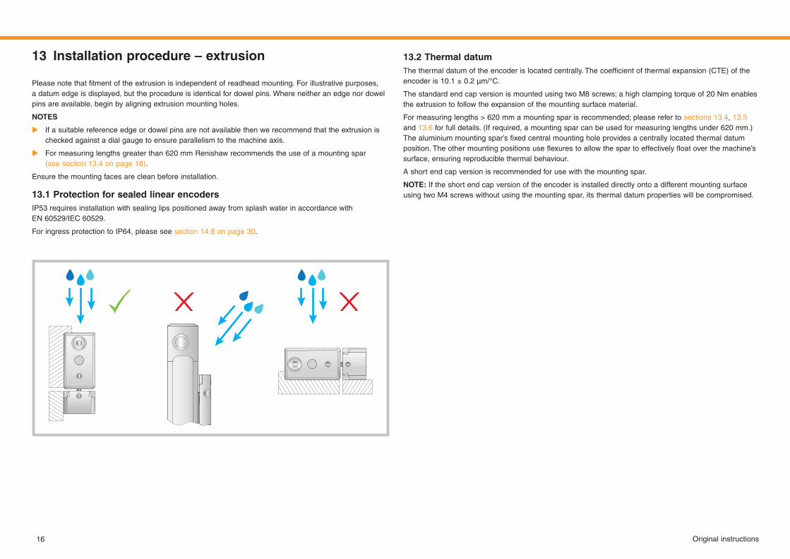
13.1 Protection for sealed linear encodersIP53 requires installation with sealing lips positioned away from splash water in accordance with EN 60529/IEC60529.
For ingress protection to IP64, please see section 14.8 on page 30.
13.2 Thermal datumThethermaldatumoftheencoderislocatedcentrally.Thecoefficientofthermalexpansion(CTE)oftheencoderis10.1 ± 0.2 μm/°C.
ThestandardendcapversionismountedusingtwoM8screws;ahighclampingtorqueof20 Nmenablesthe extrusion to follow the expansion of the mounting surface material.
Formeasuringlengths> 620 mmamountingsparisrecommended;pleaserefertosections 13.4, 13.5 and 13.6 for full details. (If required, a mounting spar can be used for measuring lengths under 620 mm.) Thealuminiummountingspar’sfixedcentralmountingholeprovidesacentrallylocatedthermaldatumposition.Theothermountingpositionsuseflexurestoallowthespartoeffectivelyfloatoverthemachine’ssurface, ensuring reproducible thermal behaviour.
A short end cap version is recommended for use with the mounting spar.
NOTE: If the short end cap version of the encoder is installed directly onto a different mounting surface using two M4 screws without using the mounting spar, its thermal datum properties will be compromised.
17Original instructions
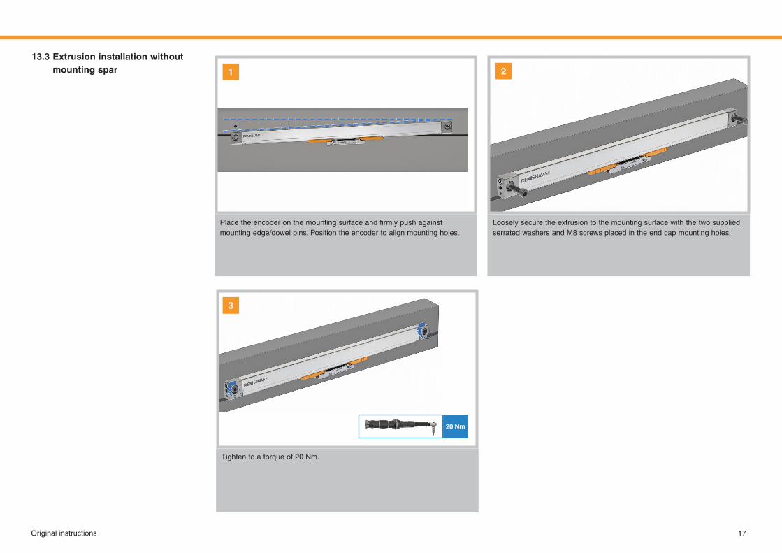
Placetheencoderonthemountingsurfaceandfirmlypushagainstmounting edge/dowel pins. Position the encoder to align mounting holes.
Loosely secure the extrusion to the mounting surface with the two supplied serrated washers and M8 screws placed in the end cap mounting holes.
Tighten to a torque of 20 Nm.
2
3
13.3 Extrusion installation without mounting spar
20 Nm
1
8 Nm
2 Nm
18 Original instructions
1 2
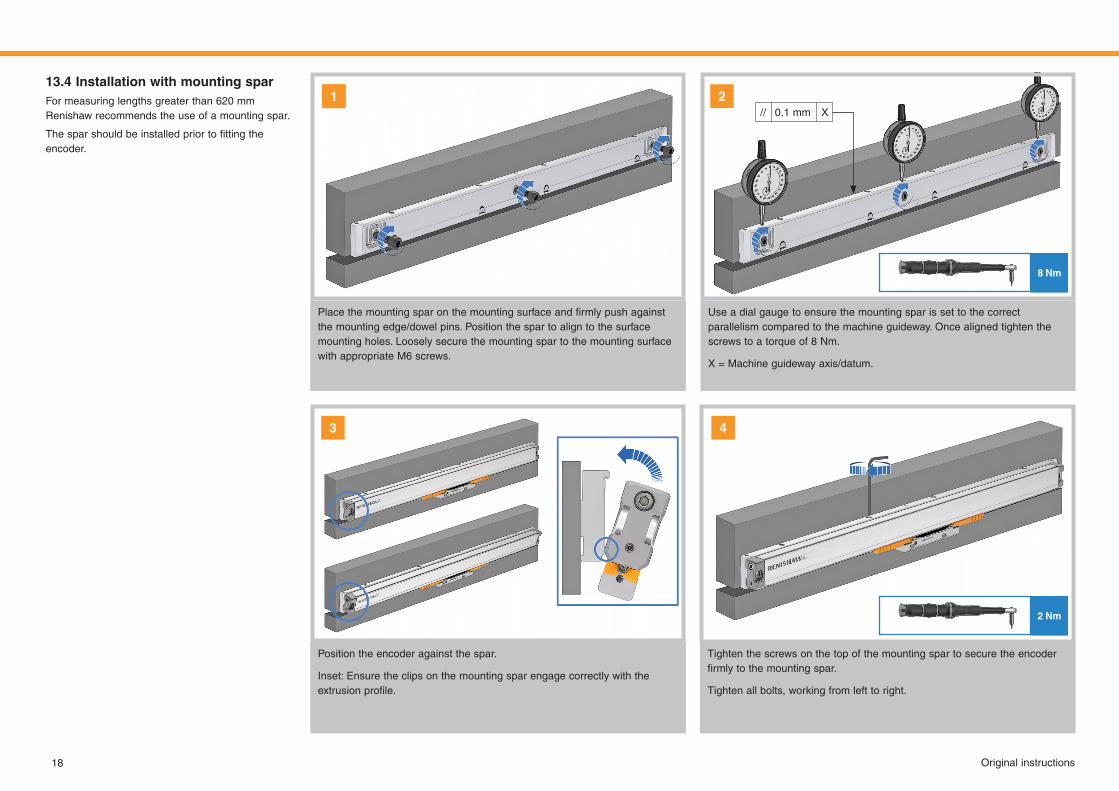
Use a dial gauge to ensure the mounting spar is set to the correct parallelism compared to the machine guideway. Once aligned tighten the screws to a torque of 8 Nm.
X = Machine guideway axis/datum.
Placethemountingsparonthemountingsurfaceandfirmlypushagainstthe mounting edge/dowel pins. Position the spar to align to the surface mounting holes. Loosely secure the mounting spar to the mounting surface with appropriate M6 screws.
Position the encoder against the spar.
Inset: Ensure the clips on the mounting spar engage correctly with the extrusionprofile.
Tighten the screws on the top of the mounting spar to secure the encoder firmlytothemountingspar.
Tighten all bolts, working from left to right.
13.4 Installation with mounting sparFormeasuringlengthsgreaterthan620 mmRenishaw recommends the use of a mounting spar.
Thesparshouldbeinstalledpriortofittingtheencoder.
3 4
1// X0.1 mm
19Original instructions
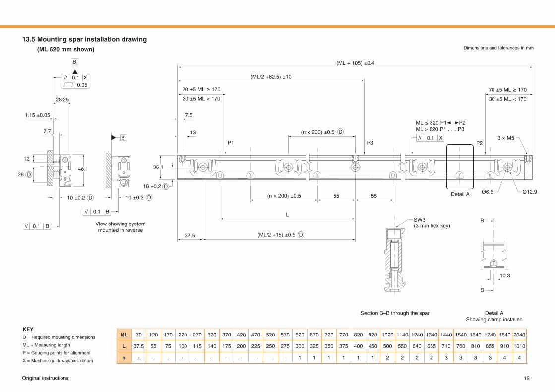
ML 70 120 170 220 270 320 370 420 470 520 570 620 670 720 770 820 920 1020 1140 1240 1340 1440 1540 1640 1740 1840 2040
L 37.5 55 75 100 115 140 175 200 225 250 275 300 325 350 375 400 450 500 550 640 655 710 760 810 855 910 1010
n - - - - - - - - - - - 1 1 1 1 1 1 2 2 2 2 3 3 3 3 4 4
KEYD = Required mounting dimensions
ML = Measuring length
P = Gauging points for alignment
X = Machine guideway/axis datum
Section B–B through the spar Detail AShowing clamp installed
View showing system mounted in reverse
13.5 Mountingsparinstallationdrawing(ML620 mmshown) Dimensions and tolerances in mm
(ML+ 105)±0.4
(ML/2+62.5)±10
(ML/2+15)±0.5
(n × 200) ±0.5
(n × 200) ±0.5
L
55 55
7.5
37.5
13
P1 P3 P2
Ø6.6Detail A Ø12.9
3 × M5
36.1
18 ±0.2
10 ±0.2
B
B
10.3
SW3(3 mmhexkey)
70±5ML≥ 170
30±5ML< 170
ML≤ 820P1 P2ML> 820P1. . . P3
70±5ML≥ 170
30±5ML< 170
D
B
B
D
D// X0.1
26
28.25
7.7
12
1.15 ±0.05
48.1
10 ±0.2
D
//
//
//
X
B
B
0.1
0.1
0.1
0.05
DD
20 Original instructions
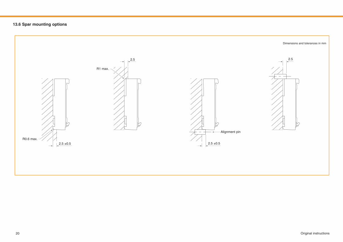
13.6 Spar mounting options
Dimensions and tolerances in mm
R0.6 max.
R1 max.
2.5 ±0.5 2.5 ±0.5
Alignment pin
2.5 2.5
21Original instructions
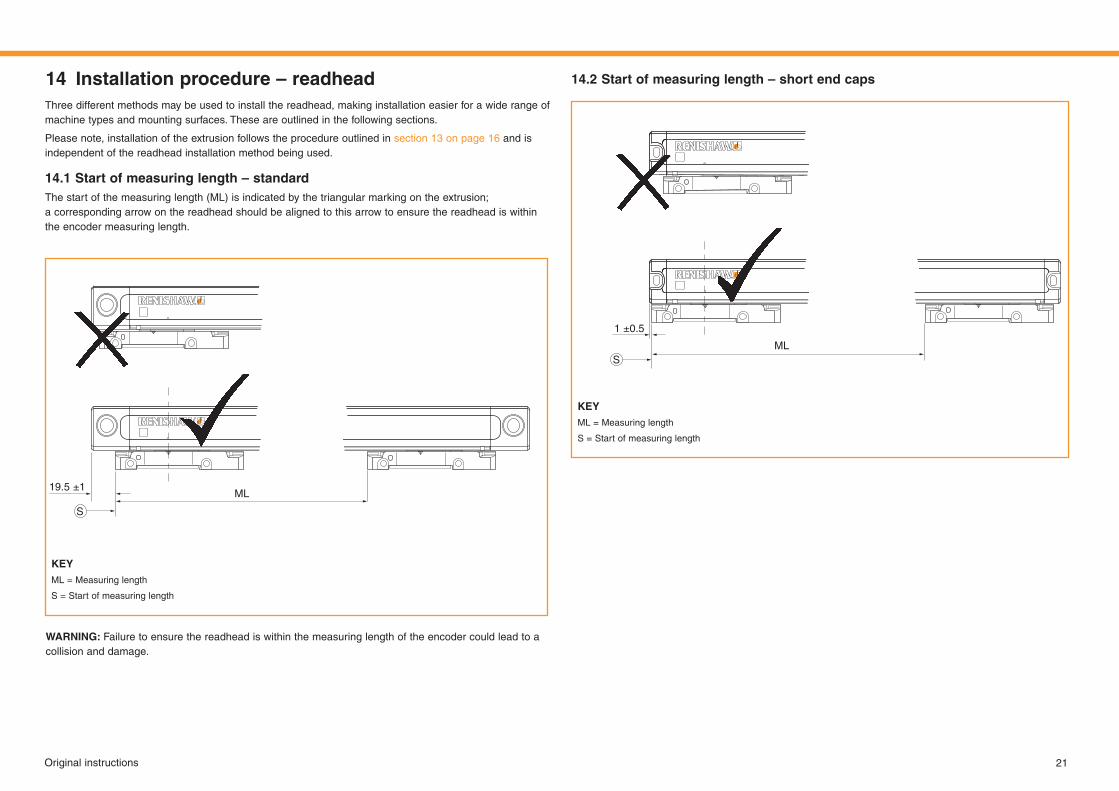
Three different methods may be used to install the readhead, making installation easier for a wide range of machine types and mounting surfaces. These are outlined in the following sections.
Please note, installation of the extrusion follows the procedure outlined in section 13 on page 16 and is independent of the readhead installation method being used.
14.1 Start of measuring length – standardThe start of the measuring length (ML) is indicated by the triangular marking on the extrusion; a corresponding arrow on the readhead should be aligned to this arrow to ensure the readhead is within the encoder measuring length.
14 Installation procedure – readhead 14.2 Start of measuring length – short end caps
WARNING: Failure to ensure the readhead is within the measuring length of the encoder could lead to a collision and damage.
KEYML = Measuring length
S = Start of measuring length
S
19.5 ±1ML
KEYML = Measuring length
S = Start of measuring length
SML
1 ±0.5
22 Original instructions
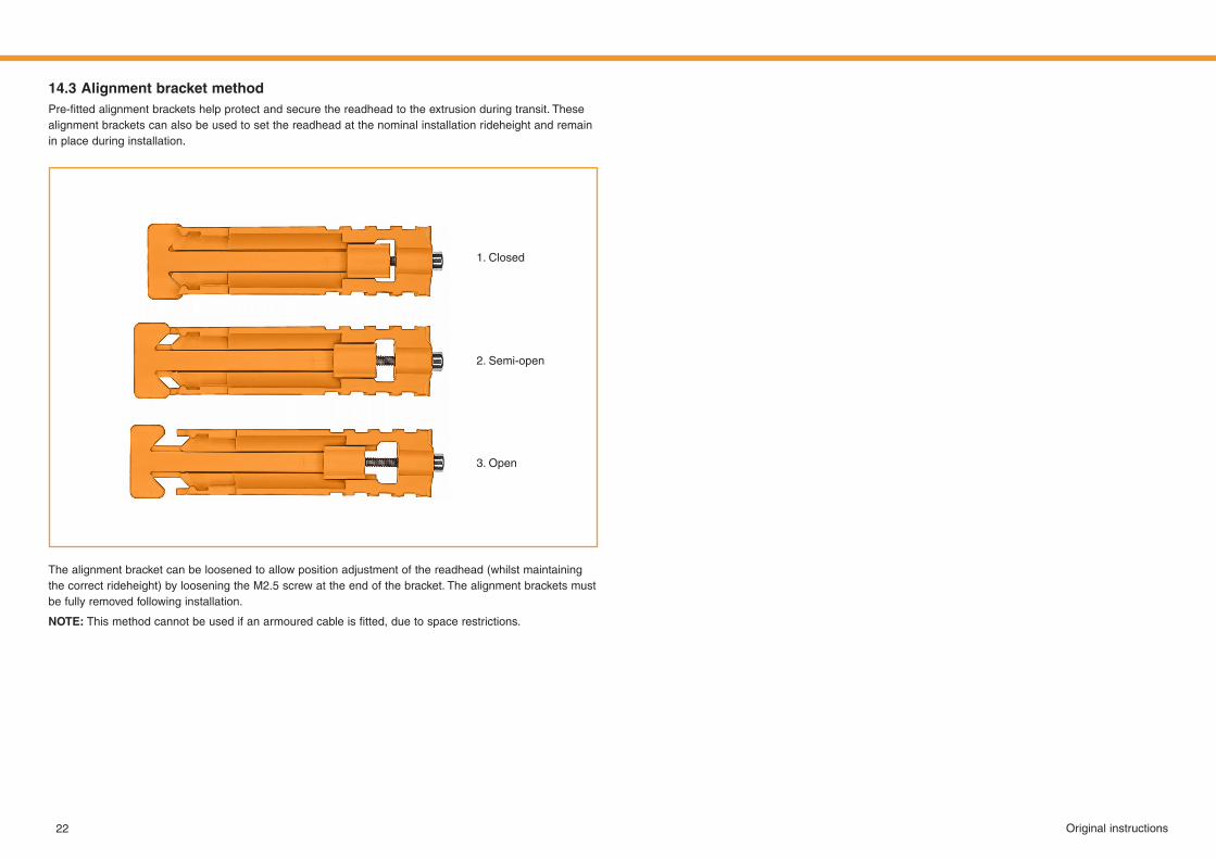
14.3 Alignment bracket methodPre‑fittedalignmentbracketshelpprotectandsecurethereadheadtotheextrusionduringtransit.Thesealignment brackets can also be used to set the readhead at the nominal installation rideheight and remain in place during installation.
The alignment bracket can be loosened to allow position adjustment of the readhead (whilst maintaining the correct rideheight) by loosening the M2.5 screw at the end of the bracket. The alignment brackets must be fully removed following installation.
NOTE:Thismethodcannotbeusedifanarmouredcableisfitted,duetospacerestrictions.
1. Closed
2. Semi-open
3. Open
Original instructions 23
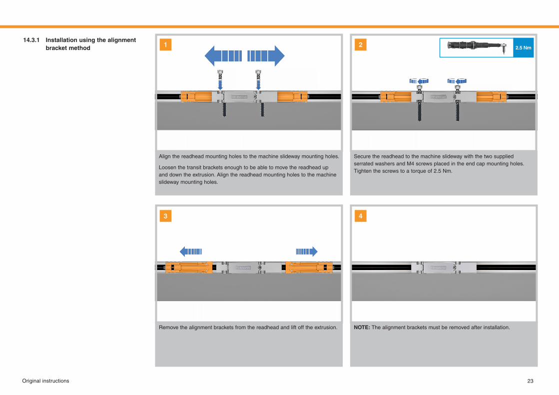
Align the readhead mounting holes to the machine slideway mounting holes.
Loosen the transit brackets enough to be able to move the readhead up and down the extrusion. Align the readhead mounting holes to the machine slideway mounting holes.
Secure the readhead to the machine slideway with the two supplied serrated washers and M4 screws placed in the end cap mounting holes. Tighten the screws to a torque of 2.5 Nm.
Remove the alignment brackets from the readhead and lift off the extrusion. NOTE: The alignment brackets must be removed after installation.
14.3.1 Installation using the alignment bracket method 1 2
3 4
2.5 Nm
2.5 Nm
24 Original instructions
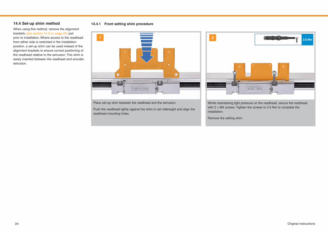
Place set-up shim between the readhead and the extrusion.
Push the readhead lightly against the shim to set rideheight and align the readhead mounting holes.
Whilst maintaining light pressure on the readhead, secure the readhead with2 × M4screws.Tightenthescrewsto2.5 Nmtocompletetheinstallation.
Remove the setting shim.
14.4 Set-up shim methodWhen using this method, remove the alignment brackets (see section 14.3 on page 22) just prior to installation. Where access to the readhead from either side is restricted in the installation position, a set-up shim can be used instead of the alignment brackets to ensure correct positioning of the readhead relative to the extrusion. This shim is easily inserted between the readhead and encoder extrusion.
14.4.1 Front setting shim procedure
1 2
2.5 Nm
Original instructions 25
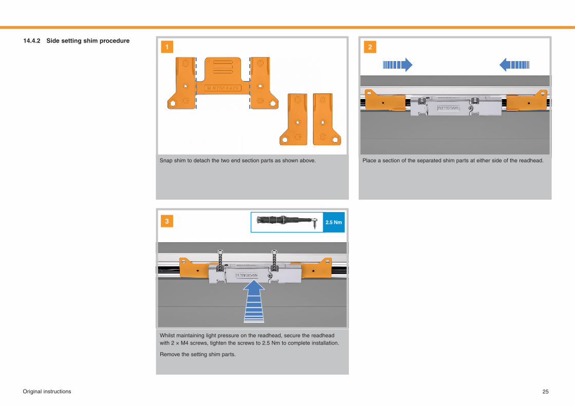
Snap shim to detach the two end section parts as shown above. Place a section of the separated shim parts at either side of the readhead.
14.4.2 Side setting shim procedure
Whilst maintaining light pressure on the readhead, secure the readhead with2 × M4screws,tightenthescrewsto2.5 Nmtocompleteinstallation.
Remove the setting shim parts.
3
21
3 mm
26 Original instructions
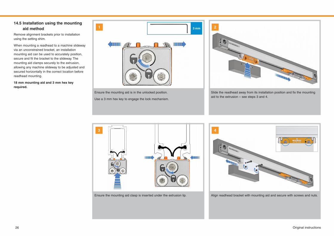
Ensure the mounting aid is in the unlocked position.
Usea3 mmhexkeytoengagethelockmechanism.
Ensure the mounting aid clasp is inserted under the extrusion lip. Align readhead bracket with mounting aid and secure with screws and nuts.
Slidethereadheadawayfromitsinstallationpositionandfixthemountingaid to the extrusion – see steps 3 and 4.
14.5 Installation using the mounting aid method
Remove alignment brackets prior to installation using the setting shim.
When mounting a readhead to a machine slideway via an unconstrained bracket, an installation mounting aid can be used to accurately position, secureandfitthebrackettotheslideway.Themounting aid clamps securely to the extrusion, allowing any machine slideway to be adjusted and securedhorizontallyinthecorrectlocationbeforereadhead mounting.
18 mm mounting aid and 3 mm hex key required.
1 2
3 4
2.5 Nm
Original instructions 27
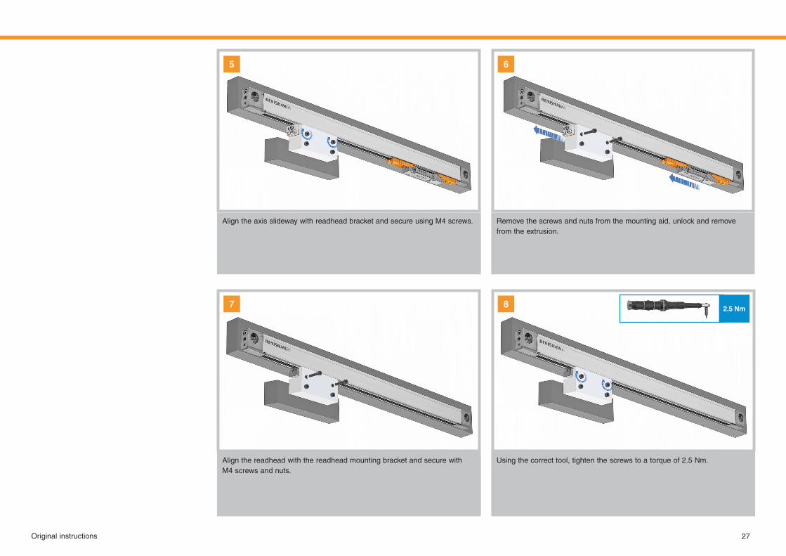
Align the axis slideway with readhead bracket and secure using M4 screws.
Align the readhead with the readhead mounting bracket and secure with M4 screws and nuts.
Remove the screws and nuts from the mounting aid, unlock and remove from the extrusion.
5 6
7 8
Usingthecorrecttool,tightenthescrewstoatorqueof2.5 Nm.
1 mm
A B
Connector key edge
28 Original instructions
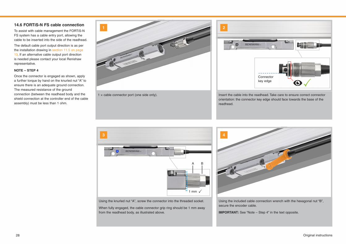
14.6 FORTiS-N FS cable connectionTo assist with cable management the FORTiS-N FS system has a cable entry port, allowing the cable to be inserted into the side of the readhead.
The default cable port output direction is as per the installation drawing in section 11.5 on page 13. If an alternative cable output port direction is needed please contact your local Renishaw representative.
NOTE – STEP 4
Once the connector is engaged as shown, apply a further torque by hand on the knurled nut “A” to ensure there is an adequate ground connection. The measured resistance of the ground connection (between the readhead body and the shield connection at the controller end of the cable assembly)mustbelessthan1 ohm.
1 × cable connector port (one side only).
Using the knurled nut “A”, screw the connector into the threaded socket.
Whenfullyengaged,thecableconnectorgripringshouldbe1 mmawayfrom the readhead body, as illustrated above.
Using the included cable connection wrench with the hexagonal nut “B”, secure the encoder cable.
IMPORTANT: See “Note – Step 4” in the text opposite.
1
3 4
2
Insert the cable into the readhead. Take care to ensure correct connector orientation: the connector key edge should face towards the base of the readhead.

29Original instructions
14.7 Validating an installationTovalidatetheencoderinstallationtheset‑upLEDprovidesinstantverificationoftheencoder’ssignalstrength and therefore its accurate alignment and installation.
The encoder requires power to enable the set-up LED; this can be via an appropriate cable plugged into the machine’s controller. See section 15 on page 31 for encoder power supply requirements.
NOTE: If the set-up LED is obscured then the signal strength can be obtained using the Advanced Diagnostic Tool for absolute encoders (ADTa-100).
LED status Description Requiredaction
BLUE Signal level is optimal No adjustment required
GREEN Signal level is good No adjustment required
ORANGE Signal level is acceptableEnsure the extrusion is parallel to the
machine axis of motion (see section 11 on page 11) and adjust the readhead
to maximise the signal strength along the full axis of travel to achieve a Green or
Blue LEDRED
Signal level is NOT acceptable
FLASHING RED
Unable to determine the position
Readhead not picking up the scale due to contamination or poor installation
NOTE: Flashing LED indicates scale reading error. Flashing state is latched for
some serial interfaces.Remove power to reset.
30 Original instructions
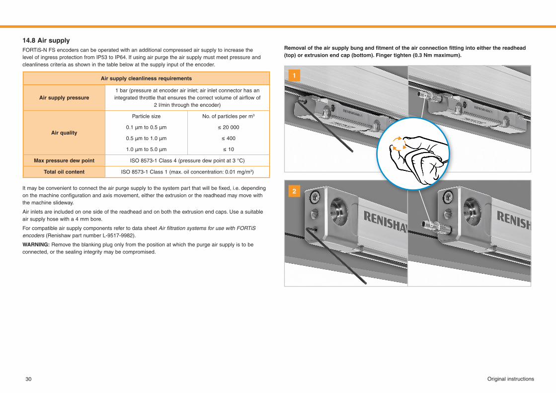
14.8 Air supplyFORTiS-N FS encoders can be operated with an additional compressed air supply to increase the level of ingress protection from IP53 to IP64. If using air purge the air supply must meet pressure and cleanliness criteria as shown in the table below at the supply input of the encoder.
Itmaybeconvenienttoconnecttheairpurgesupplytothesystempartthatwillbefixed,i.e.dependingonthemachineconfigurationandaxismovement,eithertheextrusionorthereadheadmaymovewiththe machine slideway.
Air inlets are included on one side of the readhead and on both the extrusion end caps. Use a suitable air supply hose with a 4 mm bore.
For compatible air supply components refer to data sheet Air filtration systems for use with FORTiS encoders (Renishaw part number L-9517-9982).
WARNING: Remove the blanking plug only from the position at which the purge air supply is to be connected, or the sealing integrity may be compromised.
Airsupplycleanlinessrequirements
Air supply pressure1 bar (pressure at encoder air inlet; air inlet connector has an integratedthrottlethatensuresthecorrectvolumeofairflowof
2 l/minthroughtheencoder)
Airquality
Particlesize
0.1μmto0.5μm
0.5μmto1.0μm
1.0μmto5.0μm
No. of particles per m3
≤20000
≤400
≤10
Maxpressuredewpoint ISO8573‑1Class4(pressuredewpointat3°C)
Total oil content ISO 8573-1 Class 1 (max. oil concentration: 0.01 mg/m3)
Removaloftheairsupplybungandfitmentoftheairconnectionfittingintoeitherthereadhead(top) or extrusion end cap (bottom). Finger tighten (0.3 Nm maximum).
1
2
31Original instructions
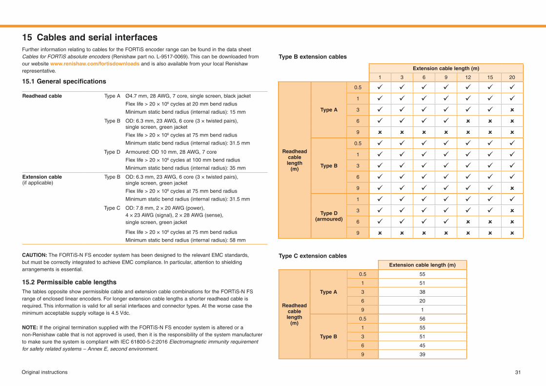
15 Cables and serial interfacesFurther information relating to cables for the FORTiS encoder range can be found in the data sheet Cables for FORTiS absolute encoders (Renishaw part no. L-9517-0069). This can be downloaded from our website www.renishaw.com/fortisdownloads and is also available from your local Renishaw representative.
15.1 Generalspecifications
CAUTION: The FORTiS-N FS encoder system has been designed to the relevant EMC standards, but must be correctly integrated to achieve EMC compliance. In particular, attention to shielding arrangements is essential.
15.2 Permissible cable lengthsThe tables opposite show permissible cable and extension cable combinations for the FORTiS-N FS range of enclosed linear encoders. For longer extension cable lengths a shorter readhead cable is required. This information is valid for all serial interfaces and connector types. At the worse case the minimum acceptable supply voltage is 4.5 Vdc.
NOTE: If the original termination supplied with the FORTiS-N FS encoder system is altered or a non-Renishaw cable that is not approved is used, then it is the responsibility of the system manufacturer tomakesurethesystemiscompliantwithIEC 61800‑5‑2:2016Electromagnetic immunity requirement for safety related systems – Annex E, second environment.
Readhead cable Type A Ø4.7 mm, 28 AWG, 7 core, single screen, black jacket
Flexlife> 20×106 cycles at 20 mm bend radius
Minimum static bend radius (internal radius): 15 mm
Type B OD: 6.3 mm, 23 AWG, 6 core (3 × twisted pairs), single screen, green jacket
Flexlife> 20×106 cycles at 75 mm bend radius
Minimum static bend radius (internal radius): 31.5 mm
Type D Armoured: OD 10 mm, 28 AWG, 7 core
Flex life > 20 × 106 cycles at 100 mm bend radius
Minimum static bend radius (internal radius): 35 mm
Extension cable (if applicable)
Type B OD: 6.3 mm, 23 AWG, 6 core (3 × twisted pairs), single screen, green jacket
Flexlife> 20×106 cycles at 75 mm bend radius
Minimum static bend radius (internal radius): 31.5 mm
Type C OD: 7.8 mm, 2 × 20 AWG (power), 4 × 23 AWG (signal), 2 × 28 AWG (sense), single screen, green jacket
Flexlife> 20×106 cycles at 75 mm bend radius
Minimum static bend radius (internal radius): 58 mm
Type B extension cables
Type C extension cablesExtension cable length (m)
Readhead cable length
(m)
Type A
0.5 55
1 51
3 38
6 20
9 1
Type B
0.5 56
1 55
3 51
6 45
9 39
Extension cable length (m)
1 3 6 9 12 15 20
Readhead cable length
(m)
Type A
0.5 1 3 6 9
Type B
0.5 1 3 6 9
Type D (armoured)
1 3 6 9
32 Original instructions
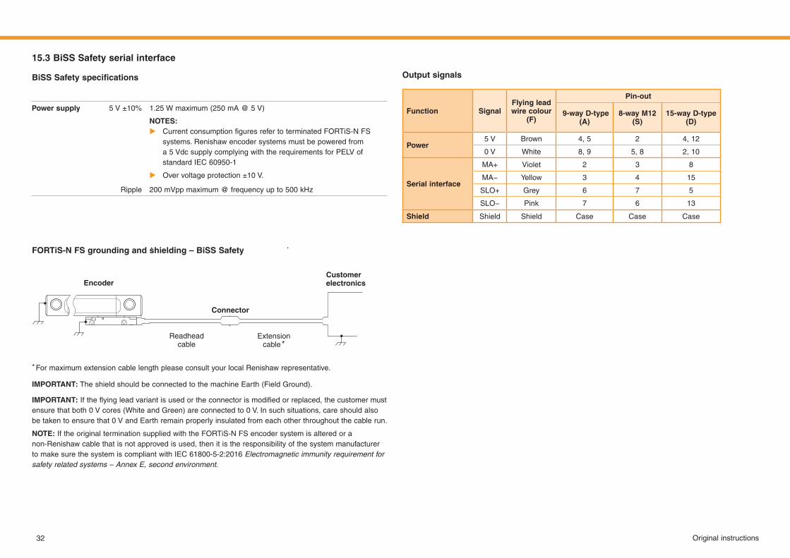
15.3 BiSS Safety serial interface
BiSSSafetyspecifications
FORTiS-N FS grounding and shielding – BiSS Safety
Power supply 5 V ±10% 1.25 W maximum (250 mA @ 5 V)
NOTES: X CurrentconsumptionfiguresrefertoterminatedFORTiS‑N FS
systems. Renishaw encoder systems must be powered from a5 VdcsupplycomplyingwiththerequirementsforPELVofstandardIEC 60950‑1
X Over voltage protection ±10 V.
Ripple 200mVppmaximum@frequencyupto500kHz
Customer electronics
Extension cable *
Encoder
Connector
Readheadcable
* For maximum extension cable length please consult your local Renishaw representative.
IMPORTANT: The shield should be connected to the machine Earth (Field Ground).
IMPORTANT:Iftheflyingleadvariantisusedortheconnectorismodifiedorreplaced,thecustomermustensurethatboth0 Vcores(WhiteandGreen)areconnectedto0 V.Insuchsituations,careshouldalsobetakentoensurethat0 VandEarthremainproperlyinsulatedfromeachotherthroughoutthecablerun.
NOTE: If the original termination supplied with the FORTiS-N FS encoder system is altered or a non-Renishaw cable that is not approved is used, then it is the responsibility of the system manufacturer tomakesurethesystemiscompliantwithIEC 61800‑5‑2:2016Electromagnetic immunity requirement for safety related systems – Annex E, second environment.
Function SignalFlying leadwire colour
(F)
Pin-out
9-way D-type(A)
8-wayM12(S)
15-way D-type(D)
Power5 V Brown 4, 5 2 4, 12
0 V White 8, 9 5, 8 2, 10
Serial interface
MA+ Violet 2 3 8
MA− Yellow 3 4 15
SLO+ Grey 6 7 5
SLO− Pink 7 6 13
Shield Shield Shield Case Case Case
Output signals
33Original instructions
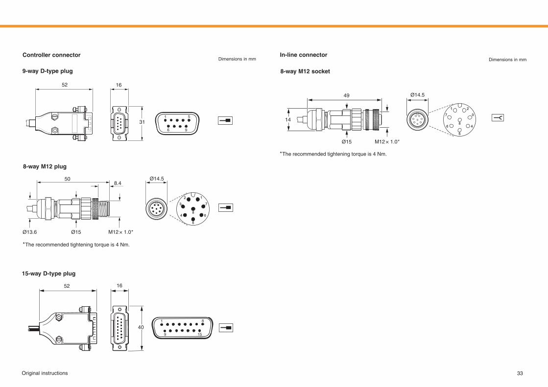
In-line connectorController connector
9-way D-type plug
15-way D-type plug
52 16
40
8-wayM12plug
* The recommended tightening torque is 4 Nm.
Ø14.5
Ø15Ø13.6
508.4
M12 × 1.0 *
Dimensions in mm Dimensions in mm
8-wayM12socket
* The recommended tightening torque is 4 Nm.
Ø14.5
Ø15
14
49
M12 × 1.0 *
31
1652
34 Original instructions
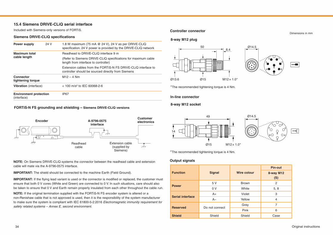
15.4 Siemens DRIVE-CLiQ serial interfaceIncluded with Siemens-only versions of FORTiS.
SiemensDRIVE-CLiQspecifications
Power supply 24 V 1.8 W maximum (75 mA @ 24 V), 24 V as per DRIVE-CLiQ specification.24VpowerisprovidedbytheDRIVE‑CLiQnetwork
Maximumtotalcable length
Readhead to DRIVE-CLiQ interface 9 m
(RefertoSiemensDRIVE‑CLiQspecificationsformaximumcablelength from interface to controller)
Extension cables from the FORTiS-N FS DRIVE-CLiQ interface to controller should be sourced directly from Siemens
Connector tighteningtorque
M12 – 4 Nm
Vibration (interface) <100m/s²toIEC60068‑2‑6
Environment protection (interface)
IP67
FORTiS-N FS grounding and shielding – Siemens DRIVE-CLiQ versions
Customer electronics
Extension cable(supplied by
Siemens)
Encoder A-9796-0575 interface
Readheadcable
NOTE: On Siemens DRIVE-CLiQ systems the connector between the readhead cable and extension cable will mate via the A-9796-0575 interface.
IMPORTANT: The shield should be connected to the machine Earth (Field Ground).
IMPORTANT:Iftheflyingleadvariantisusedortheconnectorismodifiedorreplaced,thecustomermustensurethatboth0 Vcores(WhiteandGreen)areconnectedto0 V.Insuchsituations,careshouldalsobetakentoensurethat0 VandEarthremainproperlyinsulatedfromeachotherthroughoutthecablerun.
NOTE: If the original termination supplied with the FORTiS-N FS encoder system is altered or a non-Renishaw cable that is not approved is used, then it is the responsibility of the system manufacturer tomakesurethesystemiscompliantwithIEC 61800‑5‑2:2016Electromagnetic immunity requirement for safety related systems – Annex E, second environment.
8-wayM12plug
* The recommended tightening torque is 4 Nm.
Ø14.5
Ø15Ø13.6
508.4
M12 × 1.0 *
Controller connectorDimensions in mm
In-line connector
8-wayM12socket
* The recommended tightening torque is 4 Nm.
Ø14.5
Ø15
14
49
M12 × 1.0 *
Output signals
Function Signal Wire colour
Pin-out
8-wayM12(S)
Power5 V Brown 2
0 V White 5, 8
Serial interfaceA+ Violet 3
A− Yellow 4
Reserved Do not connectGrey 7
Pink 6
Shield Shield Shield Case
35Original instructions
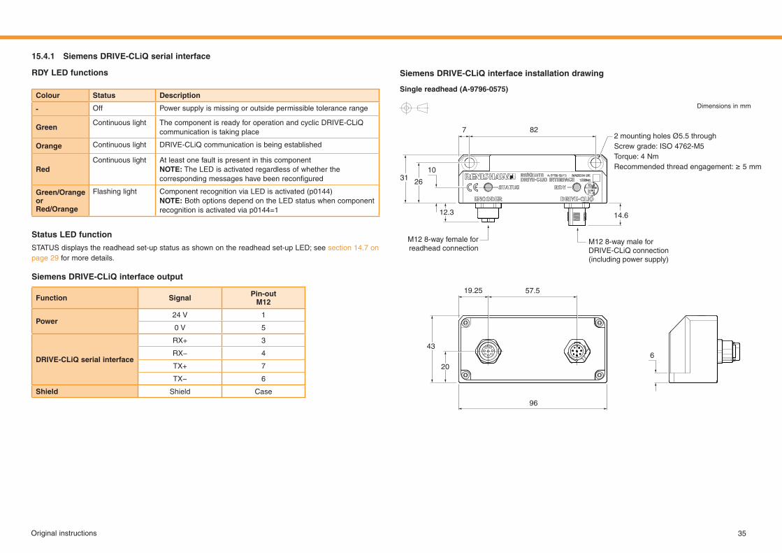
15.4.1 Siemens DRIVE-CLiQ serial interface
RDY LED functions
Colour Status Description
- Off Power supply is missing or outside permissible tolerance range
GreenContinuous light The component is ready for operation and cyclic DRIVE-CLiQ
communication is taking place
Orange Continuous light DRIVE-CLiQ communication is being established
RedContinuous light At least one fault is present in this component
NOTE: The LED is activated regardless of whether the correspondingmessageshavebeenreconfigured
Green/Orange or Red/Orange
Flashing light Component recognition via LED is activated (p0144)NOTE: Both options depend on the LED status when component recognition is activated via p0144=1
Function Signal Pin-outM12
Power24 V 1
0 V 5
DRIVE-CLiQ serial interface
RX+ 3
RX− 4
TX+ 7
TX− 6
Shield Shield Case
Status LED function
STATUS displays the readhead set-up status as shown on the readhead set-up LED; see section 14.7 on page 29 for more details.
Siemens DRIVE-CLiQ interface output
Siemens DRIVE-CLiQ interface installation drawing
Single readhead (A-9796-0575)
Dimensions in mm
M12 8-way male for DRIVE-CLiQ connection (including power supply)
M12 8-way female for readhead connection
2 mounting holes Ø5.5 throughScrew grade: ISO 4762-M5Torque: 4 NmRecommendedthreadengagement:≥5mm
827
31 26
43
20
96
14.6
19.25
12.3
57.5
10
6

T +44(0)1453524524F +44(0)1453524901E [email protected]
www.renishaw.com
Renishaw plc
New Mills, Wotton-under-EdgeGloucestershire, GL12 8JRUnited Kingdom
Part no.: M-6725-9026-01-DIssued: 12.2021
For worldwide contact details, visit www.renishaw.com/contact
Renishaw plc. Registered in England and Wales. Company no: 1106260. Registered office: New Mills, Wotton-under-Edge, Gloucestershire, GL12 8JR, UK.