FortiOS Handbook: High Availability for FortiOS...
295
FortiOS™ Handbook High Availability for FortiOS 5.0
Transcript of FortiOS Handbook: High Availability for FortiOS...

FortiOS™ HandbookHigh Availability for FortiOS 5.0

FortiOS™ Handbook High Availability for FortiOS 5.0
October 17, 2016
01-500-99686-20161017
Copyright© 2016 Fortinet, Inc. All rights reserved. Fortinet®, FortiGate®, FortiCare® and FortiGuard®, and certain other marks are registered trademarks of Fortinet, Inc., and other Fortinet names herein may also be registered and/or common law trademarks of Fortinet. All other product or company names may be trademarks of their respective owners. Performance and other metrics contained herein were attained in internal lab tests under ideal conditions, and actual performance and other resultsmay vary. Network variables, different network environments and other conditions may affect performance results. Nothing herein represents any binding commitment by Fortinet, and Fortinet disclaims all warranties, whether express or implied, except to the extent Fortinet enters a binding written contract, signed by Fortinet’s General Counsel, with a purchaser that expressly warrants that the identified product will perform according to certain expressly-identified performance metrics and, in such event, only the specific performance metrics expressly identified in such binding written contract shall be binding on Fortinet. For absolute clarity, any such warranty will be limited to performance in the same ideal conditions as in Fortinet’s internal lab tests. Fortinet disclaims in full any covenants, representations,and guarantees pursuant hereto, whether express or implied. Fortinet reserves the right to change, modify, transfer, or otherwise revise this publication without notice, and the most current version of the publication shall be applicable.
Technical Documentation docs.fortinet.com
Knowledge Base kb.fortinet.com
Customer Service & Support support.fortinet.com
Training Services training.fortinet.com
FortiGuard fortiguard.com
Document Feedback [email protected]

Table of Contents
Change Log..................................................................................................... 12
Solving the High Availability problem........................................................... 17FortiGate Cluster Protocol (FGCP) ........................................................................ 17
FortiGate Session Life Support Protocol (FGSP)................................................... 18
VRRP...................................................................................................................... 19
Fortinet redundant UTM protocol (FRUP).............................................................. 19
An introduction to the FGCP ......................................................................... 21About the FGCP..................................................................................................... 22
FGCP failover protection ................................................................................. 23Session Failover............................................................................................... 23Load Balancing ................................................................................................ 23Virtual Clustering.............................................................................................. 23Full Mesh HA.................................................................................................... 24Cluster Management........................................................................................ 24
Synchronizing the configuration (and settings that are not synchronized)............ 24
Configuring FortiGate units for FGCP HA operation ............................................. 25Connecting a FortiGate HA cluster .................................................................. 27
Active-passive and active-active HA ..................................................................... 28Active-passive HA (failover protection)............................................................ 28Active-active HA (load balancing and failover protection) ............................... 29
Identifying the cluster and cluster units ................................................................. 29Group name ..................................................................................................... 29Password ......................................................................................................... 30Group ID........................................................................................................... 30
Device failover, link failover, and session failover.................................................. 30
Primary unit selection ............................................................................................ 31Primary unit selection and monitored interfaces ............................................. 32Primary unit selection and age ........................................................................ 33Primary unit selection and device priority........................................................ 36Primary unit selection and the FortiGate unit serial number............................ 37Points to remember about primary unit selection............................................ 38
HA override ............................................................................................................ 38Override and primary unit selection................................................................. 39Controlling primary unit selection using device priority and override.............. 40Points to remember about primary unit selection when override is enabled .. 41Configuration changes can be lost if override is enabled................................ 41Override and disconnecting a unit from a cluster............................................ 42
FortiGate HA compatibility with PPPoE and DHCP............................................... 42
Page 3
HA and distributed clustering ................................................................................ 43
Hard disk configuration and HA ............................................................................ 43
FGCP high availability best practices .................................................................... 43Heartbeat interfaces ........................................................................................ 44Interface monitoring (port monitoring) ............................................................. 45Troubleshooting ............................................................................................... 45
FGCP HA terminology ........................................................................................... 45
HA web-based manager options........................................................................... 49
Configuring and connecting HA clusters ..................................................... 52About the procedures in this chapter .................................................................... 52
Example: NAT/Route mode active-passive HA configuration ............................... 52Example NAT/Route mode HA network topology ........................................... 53General configuration steps............................................................................. 53Configuring a NAT/Route mode active-passive cluster of two FortiGate-620B
units - web-based manager .......................................................................... 54Configuring a NAT/Route mode active-passive cluster of two FortiGate-620B
units - CLI ...................................................................................................... 58
Example: Transparent mode active-active HA configuration ................................ 64Example Transparent mode HA network topology.......................................... 64General configuration steps............................................................................. 65Configuring a Transparent mode active-active cluster of two FortiGate-620B
units - web-based manager .......................................................................... 66Configuring a Transparent mode active-active cluster of two FortiGate-620B
units - CLI ...................................................................................................... 70
Example: advanced Transparent mode active-active HA configuration ............... 76Example Transparent mode HA network topology.......................................... 77Configuring a Transparent mode active-active cluster of three
FortiGate-5005FA2 units - web-based manager........................................... 77Configuring a Transparent mode active-active cluster of three
FortiGate-5005FA2 units - CLI ...................................................................... 80
Example: converting a standalone FortiGate unit to a cluster............................... 84
Example: adding a new unit to an operating cluster ............................................. 86
Example: replacing a failed cluster unit ................................................................. 87
Example: HA and 802.3ad aggregated interfaces................................................. 88HA interface monitoring, link failover, and 802.3ad aggregation..................... 88HA MAC addresses and 802.3ad aggregation ................................................ 88Link aggregation, HA failover performance, and HA mode ............................. 89General configuration steps............................................................................. 89Configuring active-passive HA cluster that includes aggregated interfaces -
web-based manager ..................................................................................... 90Configuring active-passive HA cluster that includes aggregate interfaces - CLI .
94
Fortinet Technologies Inc. Page 4 FortiOS™ Handbook - High Availability for FortiOS 5.0
Example: HA and redundant interfaces............................................................... 100HA interface monitoring, link failover, and redundant interfaces................... 100HA MAC addresses and redundant interfaces .............................................. 101Connecting multiple redundant interfaces to one switch while operating in
active-passive HA mode.............................................................................. 101Connecting multiple redundant interfaces to one switch while operating in
active-active HA mode ................................................................................ 101General configuration steps........................................................................... 101Configuring active-passive HA cluster that includes redundant interfaces -
web-based manager ................................................................................... 102Configuring active-passive HA cluster that includes redundant interfaces - CLI .
106
Troubleshooting HA clusters ............................................................................... 112Ignoring hardware revisions........................................................................... 112Before you set up a cluster............................................................................ 112Troubleshooting the initial cluster configuration............................................ 113More troubleshooting information ................................................................. 115
Virtual clusters.............................................................................................. 117Virtual clustering overview ................................................................................... 117
Virtual clustering and failover protection ....................................................... 117Virtual clustering and heartbeat interfaces .................................................... 117Virtual clustering and HA override ................................................................. 118Virtual clustering and load balancing or VDOM partitioning.......................... 118
Configuring HA for virtual clustering.................................................................... 119
Example: virtual clustering with two VDOMs and VDOM partitioning ................. 121Example virtual clustering network topology................................................. 121General configuration steps........................................................................... 122Configuring virtual clustering with two VDOMs and VDOM partitioning -
web-based manager ................................................................................... 123Configuring virtual clustering with two VDOMs and VDOM partitioning - CLI......
128
Example: inter-VDOM links in a virtual clustering configuration.......................... 136Configuring inter-VDOM links in a virtual clustering configuration ................ 137
Troubleshooting virtual clustering........................................................................ 138
Full mesh HA................................................................................................. 139Full mesh HA overview ........................................................................................ 139
Full mesh HA and redundant heartbeat interfaces ........................................ 140Full mesh HA, redundant interfaces and 802.3ad aggregate interfaces ....... 140
Fortinet Technologies Inc. Page 5 FortiOS™ Handbook - High Availability for FortiOS 5.0
Example: full mesh HA configuration................................................................... 141FortiGate-620B full mesh HA configuration................................................... 142Full mesh switch configuration ...................................................................... 142Full mesh network connections ..................................................................... 142How packets travel from the internal network through the full mesh cluster and
to the Internet .............................................................................................. 142Configuring FortiGate-620B units for HA operation - web-based manager.. 143Configuring FortiGate-620B units for HA operation - CLI ............................. 147
Troubleshooting full mesh HA ............................................................................. 151
Operating a cluster....................................................................................... 152Operating a cluster .............................................................................................. 152
Operating a virtual cluster.................................................................................... 153
Managing individual cluster units using a reserved management interface........ 154Configuring the reserved management interface and SNMP remote
management of individual cluster units....................................................... 155
The primary unit acts as a router for subordinate unit management traffic ........ 159Cluster communication with RADIUS and LDAP servers .............................. 160
Clusters and FortiGuard services ........................................................................ 160FortiGuard and active-passive clusters ......................................................... 160FortiGuard and active-active clusters............................................................ 160FortiGuard and virtual clustering ................................................................... 161
Clusters and logging............................................................................................ 161Viewing and managing log messages for individual cluster units ................. 161HA log messages........................................................................................... 162Fortigate HA message "HA master heartbeat interface <intf_name> lost
neighbor information".................................................................................. 162Formatting cluster unit hard disks (log disks) ................................................ 164
Clusters and SNMP ............................................................................................. 164SNMP get command syntax for the primary unit .......................................... 164SNMP get command syntax for any cluster unit ........................................... 166Getting serial numbers of cluster units .......................................................... 167SNMP get command syntax - reserved management interface enabled...... 167
Clusters and file quarantine ................................................................................. 168
Cluster members list ............................................................................................ 168
Virtual cluster members list ................................................................................. 170
Viewing HA statistics ........................................................................................... 171
Changing the HA configuration of an operating cluster ...................................... 173
Changing the HA configuration of an operating virtual cluster............................ 173
Changing the subordinate unit host name and device priority............................ 173
Upgrading cluster firmware ................................................................................. 174Changing how the cluster processes firmware upgrades ............................. 175Synchronizing the firmware build running on a new cluster unit ................... 175
Downgrading cluster firmware............................................................................. 175
Fortinet Technologies Inc. Page 6 FortiOS™ Handbook - High Availability for FortiOS 5.0

Backing up and restoring the cluster configuration............................................. 176
Monitoring cluster units for failover ..................................................................... 177
Viewing cluster status from the CLI ..................................................................... 177Examples ....................................................................................................... 179About the HA cluster index and the execute ha manage command ............. 182Managing individual cluster units .................................................................. 184
Disconnecting a cluster unit from a cluster ......................................................... 185
Adding a disconnected FortiGate unit back to its cluster ................................... 186
HA diagnose commands ..................................................................................... 187all-xdb ............................................................................................................ 188all-vcluster...................................................................................................... 189stat ................................................................................................................. 189
HA and failover protection........................................................................... 190About active-passive failover............................................................................... 190
Device failure ................................................................................................. 191Link failure...................................................................................................... 191Session failover.............................................................................................. 191Primary unit recovery ..................................................................................... 191
About active-active failover ................................................................................. 192
Device failover ..................................................................................................... 192
HA heartbeat and communication between cluster units.................................... 193Heartbeat interfaces ...................................................................................... 193Connecting HA heartbeat interfaces.............................................................. 195Heartbeat packets and heartbeat interface selection.................................... 195Interface index and display order .................................................................. 196HA heartbeat interface IP addresses ............................................................. 196Heartbeat packet Ethertypes ......................................................................... 197Modifying heartbeat timing ............................................................................ 198Enabling or disabling HA heartbeat encryption and authentication .............. 199
Cluster virtual MAC addresses ............................................................................ 200Changing how the primary unit sends gratuitous ARP packets after a failover ...
201Disabling gratuitous ARP packets after a failover ......................................... 202How the virtual MAC address is determined ................................................. 202Displaying the virtual MAC address............................................................... 204Diagnosing packet loss with two FortiGate HA clusters in the same broadcast
domain......................................................................................................... 205
Fortinet Technologies Inc. Page 7 FortiOS™ Handbook - High Availability for FortiOS 5.0
Synchronizing the configuration .......................................................................... 207Configuration settings that are not synchronized.......................................... 207Disabling automatic configuration synchronization ....................................... 208Incremental synchronization .......................................................................... 208Periodic synchronization................................................................................ 209Console messages when configuration synchronization succeeds .............. 210Console messages when configuration synchronization fails ....................... 210Comparing checksums of cluster units ......................................................... 212How to diagnose HA out of sync messages.................................................. 213Recalculating the checksums to resolve out of sync messages ................... 215
Synchronizing kernel routing tables..................................................................... 215Configuring graceful restart for dynamic routing failover .............................. 215Controlling how the FGCP synchronizes kernel routing table updates ......... 217
Synchronizing IPsec VPN SAs............................................................................. 218
Link failover (port monitoring or interface monitoring)......................................... 219If a monitored interface on the primary unit fails ........................................... 220If a monitored interface on a subordinate unit fails ....................................... 221How link failover maintains traffic flow .......................................................... 221Recovery after a link failover and controlling primary unit selection (controlling
falling back to the prior primary unit)........................................................... 222Preventing a primary unit change after a failed link is restored..................... 223Testing link failover ........................................................................................ 223Updating MAC forwarding tables when a link failover occurs....................... 223Multiple link failures ....................................................................................... 224Example link failover scenarios...................................................................... 224
Subsecond failover .............................................................................................. 225
Remote link failover ............................................................................................. 226Adding HA remote IP monitoring to multiple interfaces ................................ 228Changing the ping server failover threshold .................................................. 229Monitoring multiple IP addresses from one interface .................................... 230Flip timeout .................................................................................................... 230Detecting HA remote IP monitoring failovers................................................. 231
Fortinet Technologies Inc. Page 8 FortiOS™ Handbook - High Availability for FortiOS 5.0
Session failover (session pick-up) ....................................................................... 231If session pickup is not selected.................................................................... 231Improving session synchronization performance .......................................... 232Session failover not supported for all sessions ............................................. 233IPv6, NAT64, and NAT66 session failover ..................................................... 234SIP session failover........................................................................................ 234Explicit web proxy, WCCP, and WAN optimization session failover ............. 234SSL offloading and HTTP multiplexing session failover ................................ 234IPsec VPN session failover ............................................................................ 234SSL VPN session failover and SSL VPN authentication failover ................... 234PPTP and L2TP VPN sessions ...................................................................... 235UDP, ICMP, multicast and broadcast packet session failover ...................... 235FortiOS Carrier GTP session failover ............................................................. 235Active-active HA subordinate units sessions can resume after a failover ..... 236
WAN optimization and HA ................................................................................... 236
Failover and attached network equipment .......................................................... 236
Monitoring cluster units for failover ..................................................................... 237
NAT/Route mode active-passive cluster packet flow.......................................... 237Packet flow from client to web server ........................................................... 238Packet flow from web server to client ........................................................... 238When a failover occurs .................................................................................. 239
Transparent mode active-passive cluster packet flow ........................................ 239Packet flow from client to mail server............................................................ 240Packet flow from mail server to client............................................................ 240When a failover occurs .................................................................................. 241
Failover performance ........................................................................................... 241Device failover performance .......................................................................... 241Link failover performance .............................................................................. 242Reducing failover times ................................................................................. 243
HA and load balancing................................................................................. 244Load balancing overview ..................................................................................... 244
Load balancing schedules ............................................................................. 245Selecting which packets are load balanced .................................................. 246More about active-active failover .................................................................. 246HTTPS sessions, active-active load balancing, and proxy servers ............... 246Using FortiGate network processor interfaces to accelerate active-active HA
performance ................................................................................................ 247
Configuring load balancing settings .................................................................... 248Selecting a load balancing schedule ............................................................. 248Load balancing UTM sessions, TCP sessions, and UDP sessions ............... 248Configuring weighted-round-robin weights................................................... 249Dynamically optimizing weighted load balancing according to how busy cluster
units are ....................................................................................................... 251
Fortinet Technologies Inc. Page 9 FortiOS™ Handbook - High Availability for FortiOS 5.0
NAT/Route mode active-active cluster packet flow ............................................ 255Packet flow from client to web server ........................................................... 255Packet flow from web server to client ........................................................... 256When a failover occurs .................................................................................. 257
Transparent mode active-active cluster packet flow........................................... 257Packet flow from client to mail server............................................................ 258Packet flow from mail server to client............................................................ 259When a failover occurs .................................................................................. 260
HA with FortiGate-VM and third-party products ....................................... 261FortiGate-VM for VMware HA configuration........................................................ 261
FortiGate VM for Hyper-V HA configuration ........................................................ 262
Troubleshooting layer-2 switches........................................................................ 262Forwarding delay on layer 2 switches ........................................................... 262
Failover issues with layer-3 switches .................................................................. 262
Changing spanning tree protocol settings for some switches ............................ 263Spanning Tree protocol (STP)........................................................................ 263Bridge Protocol Data Unit (BPDU) ................................................................. 263
Failover and attached network equipment .......................................................... 263
Ethertype conflicts with third-party switches ...................................................... 264
LACP, 802.3ad aggregation and third-party switches ........................................ 264
VRRP.............................................................................................................. 265Adding a VRRP virtual router to a FortiGate interface ................................... 266VRRP virtual MAC address ............................................................................ 266
Configuring VRRP................................................................................................ 267Example VRRP configuration: two FortiGate units in a VRRP group ............ 267Example VRRP configuration: VRRP load balancing two FortiGate units and two
VRRP groups ............................................................................................... 268Optional VRRP configuration settings ........................................................... 270
FortiGate Session Life Support Protocol (FGSP)....................................... 271Synchronizing the configuration .......................................................................... 272
Synchronizing UDP and ICMP (connectionless) sessions................................... 273
Synchronizing NAT sessions ............................................................................... 273
Synchronizing expectation (asymmetric) sessions.............................................. 273
UTM Flow-based Inspection and Asymmetric Traffic ......................................... 274
Notes and limitations ........................................................................................... 274
Configuring FGSP HA.......................................................................................... 275
Configuring the session synchronization link ...................................................... 275
Basic example configuration ............................................................................... 276
Verifying FGSP configuration and synchronization ............................................. 278FGSP configuration summary and status...................................................... 279Verifying that sessions are synchronized....................................................... 280
Fortinet Technologies Inc. Page 10 FortiOS™ Handbook - High Availability for FortiOS 5.0

Configuring FRUP......................................................................................... 281FRUP configuration example............................................................................... 282
Configuring FGT-A......................................................................................... 282Configuring FGT-B......................................................................................... 283Connecting, testing and operating the FRUP cluster .................................... 283
Index .............................................................................................................. 286
Fortinet Technologies Inc. Page 11 FortiOS™ Handbook - High Availability for FortiOS 5.0

Change Log
Date Change Description
17 October, 2016 Added a caution about enabling BGP graceful restart to “Configuring graceful restart for dynamic routing failover” on page 215.
1 April 2015 Added “FortiGate-VM for VMware HA configuration” on page 261 and “FortiGate VM for Hyper-V HA configuration” on page 262.
Changes to “Synchronizing kernel routing tables” on page 215.
Added “Verifying FGSP configuration and synchronization” on page 278
7 August 2014 Provided more information about session failover in “FortiGate Cluster Protocol (FGCP)” on page 17 and “FortiGate Session Life Support Protocol (FGSP)” on page 18.
27 May 2014 Added the new section “Synchronizing the configuration (and settings that are not synchronized)” on page 24.
Changed the Password description in “HA web-based manager options” on page 49.
Added a note about virtual clustering device priorities not being synchronized in a virtual cluster to “Virtual clustering and load balancing or VDOM partitioning” on page 118.
Added more information about the ha-priority setting not being synchronized to “Remote link failover” on page 226.
Added a note about setting the ha-priority for all cluster units to “Changing the ping server failover threshold” on page 229.
Changes to “Dynamically optimizing weighted load balancing according to how busy cluster units are” on page 251.
Changes to “Synchronizing NAT sessions” on page 273 and “Synchronizing expectation (asymmetric) sessions” on page 273. New Section: “UTM Flow-based Inspection and Asymmetric Traffic” on page 274.
2 May 2014 Added note about DHCP and HA to “Example: NAT/Route mode active-passive HA configuration” on page 52 and “Example: converting a standalone FortiGate unit to a cluster” on page 84.
17 April 2014 New section “Disabling gratuitous ARP packets after a failover” on page 202.
Updates to “Updating MAC forwarding tables when a link failover occurs” on page 223.
Page 12

Fortinet Technologies Inc.
24 February 2014 Changes to “Fortinet redundant UTM protocol (FRUP)” on page 19.
General edits to “An introduction to the FGCP” on page 21.
Corrections and new information added to “HA override” on page 38.
Added a bullet point about resuming sessions after a failover of session pickup is not selected to “FGCP high availability best practices” on page 43.
New section “Formatting cluster unit hard disks (log disks)” on page 164.
New section “Recalculating the checksums to resolve out of sync messages” on page 215.
New section “Preventing a primary unit change after a failed link is restored” on page 223.
New section “If session pickup is not selected” on page 231.
Added more information about session pickup to the introduction to “FortiGate Session Life Support Protocol (FGSP)” on page 271.
Change to the interface types supported by FGSP HA added to the section “Notes and limitations” on page 274.
New chapter “Configuring FRUP” on page 281.
13 December 2013 Reviewed and updated all documented diagnose commands.
Some corrections to the opening paragraphs and the note under “Solving the High Availability problem” on page 17.
Corrected “Displaying cluster unit age differences” on page 34. The diagnose sys ha dump 1 command has been removed. Instead, use diagnose sys ha dump-by all-vcluster.
Added “HA and distributed clustering” on page 43.
Added “Ignoring hardware revisions” on page 112.
Added “HA diagnose commands” on page 187.
Added more information to “Recovery after a link failover and controlling primary unit selection (controlling falling back to the prior primary unit)” on page 222.
Corrected the first virtual MAC addresses example in “VRRP virtual MAC address” on page 266.
Added a note about FCSP between FortiOS firmware versions to “FortiGate Session Life Support Protocol (FGSP)” on page 271.
10 April 2013 New section: “Synchronizing the configuration” on page 272.
Date Change Description
Feedback Page 13 FortiOS™ Handbook v5.0High Availability for FortiOS 5.0

3 April, 2013 Feature name change: “FortiGate Session Life Support Protocol (FGSP)” on page 18 and “FortiGate Session Life Support Protocol (FGSP)” on page 271.
Fixed errors about FGSP HA and NAT sessions in “Synchronizing NAT sessions” on page 273 and “Notes and limitations” on page 274.
Changed the limit on the number of monitored interfaces to 64 in “Link failover (port monitoring or interface monitoring)” on page 219 and “HA web-based manager options” on page 49. Was 16.
Changes to “Load balancing” on page 47 and “Load balancing overview” on page 244 to refine the definition of cluster load balancing.
27 February, 2013 Information about session pickup options for the standalone session and configuration feature has been added to the following sections (both of which have also been renamed:
• “FortiGate Session Life Support Protocol (FGSP)” on page 18
• “FortiGate Session Life Support Protocol (FGSP)” on page 271
Added missing information about session pickup for UDP and ICMP sessions for FGCP HA to the following sections:
• “Session failover (session pick-up)” on page 231
• “UDP, ICMP, multicast and broadcast packet session failover” on page 235.
Added missing information about load balancing UDP sessions for FGCP HA to the following sections:
• “Load Balancing” on page 23
• “Load balancing overview” on page 244
• “Selecting which packets are load balanced” on page 246
• “Using FortiGate network processor interfaces to accelerate active-active HA performance” on page 247
• “Load balancing UTM sessions, TCP sessions, and UDP sessions” on page 248
13 January, 2013 Added missing graphic to “FortiGate Session Life Support Protocol (FGSP)” on page 18. Corrected and added new information to “Fortinet redundant UTM protocol (FRUP)” on page 19 including a link to a FRUP recipe on the Fortinet Community website (http://community.fortinet.com).
26 October, 2012 New FortiOS 5.0 release.
Date Change Description
Page 14 FortiOS™ Handbook v5.0 High Availability for FortiOS 5.0

Fortinet Technologies Inc.
Feedback Page 15 FortiOS™ Handbook v5.0High Availability for FortiOS 5.0

This FortiOS Handbook chapter contains the following sections:
Solving the High Availability problem describes the high availability problem and introduces the FortiOS solutions described in this document (FGCP, VRRP, and standalone session synchronization).
An introduction to the FGCP introduces the FGCP clustering protocol and many of its features and terminology.
Configuring and connecting HA clusters describes configuring HA clusters and contains HA clustering configuration examples.
Virtual clusters describes configuring HA virtual clusters and contains virtual clustering configuration examples.
Full mesh HA describes configuring FortiGate Full mesh HA and contains a full mesh HA configuration example.
Operating a cluster describes how to operate a cluster and includes detailed information about how various FortiGate systems operate differently in a cluster.
HA and failover protection describes in detail how FortiGate HA device failover, link failover, and session failover work.
HA and load balancing describes in detail how FortiGate HA active-active load balancing load balances sessions.
HA with FortiGate-VM and third-party products describes how FortiGate units interact with third-party products.
VRRP describes FortiOS support of the Virtual Router Redundancy Protocol (VRRP) and its use for high availability.
FortiGate Session Life Support Protocol (FGSP) describes the FortiGate standalone session synchronization feature and its use for high availability.
Configuring FRUP describes how to set up a FortiGate Redundant UTM Protocol (FRUP) cluster consisting of two FortiGate-100D units.
•
Page 16

Solving the High Availability problem
The basic high availability (HA) problem for TCP/IP networks and security gateways is keeping network traffic flowing. Uninterrupted traffic flow is a critical component for online systems and media because critical business processes quickly come to a halt when the network is down.
The security gateway is a crucial component of most networks since all traffic passes through it. A standalone network security gateway is a single point of failure that is vulnerable to any number of software or hardware problems that could compromise the device and bring all traffic on the network to a halt.
A common solution to the high availability problem is to eliminate the security gateway as single point of failure by introducing redundancy. With two or more redundant security gateways, if one fails, the remaining one or more gateways keep the traffic flowing. FortiOS provides four redundancy solutions: industry standard VRRP as well as three proprietary solutions: FortiGate Cluster Protocol (FGCP) high availability, FortiGate Session Life Support Protocol (FGSP) high availability, and the Fortinet Redundant UTM protocol (FRUP) high availability.
A strong and flexible High availability solution is required for many mission-critical firewall and UTM applications. Each FortiOS high availability solution can be fine tuned to fit into many different network scenarios.
FortiGate Cluster Protocol (FGCP)
FGCP HA provides a solution for two key requirements of critical enterprise networking components: enhanced reliability and increased performance. Enhanced reliability is achieved through device failover protection, link failover protection, and remote link failover protection. Also contributing to enhanced reliability is session failover protection for most IPv4 and IPv6 sessions including TCP, UDP, ICMP, IPsec VPN, and NAT sessions. Increased performance is achieved though active-active HA load balancing. Extended FGCP features include full mesh HA and virtual clustering. You can also fine tune the performance of the FGCP to change how a cluster forms and shares information among cluster units and how the cluster responds to failures.
When configured onto your network an FGCP cluster appears to be a single FortiGate unit operating in NAT/Route or Transparent mode and configuration synchronization allows you to configure a cluster in the same way as a standalone FortiGate unit. If a failover occurs, the cluster recovers quickly and automatically and also sends administrator notifications so that the problem that caused the failure can be corrected and any failed equipment restored.
You can combine more than one high availability solution into a single configuration. A common reason for doing this could be to add VRRP to an FGCP or FGSP configuration.
InternalNetwork
FortiGateHigh Availability
Cluster
External
RouterExternal
Switch
Internal
Switch
ExtxtS
S
Page 17

The FGCP is compatible with most network environments and most networking equipment. While initial configuration is relatively quick and easy, a large number of tools and configuration options are available to fine tune the cluster for most situations.
FortiGate Session Life Support Protocol (FGSP)
In a network that already includes load balancing (either with load balancers or routers) for traffic redundancy, two identical FortiGate units can be integrated into the load balancing configuration using the FortiGate Session Life Support Protocol (FGSP). The external load balancers or routers can distribute sessions among the FortiGate units and the FGSP performs session synchronization of IPv4 and IPv6 TCP, UDP, ICMP, expectation, and NAT sessions to keep the session tables of both FortiGate units synchronized.
If one of the FortiGate units fails, session failover occurs and active sessions fail over to the unit that is still operating. This failover occurs without any loss of data. As well, the external load balancers or routers detect the failover and re-distribute all sessions to the unit that is still operating.
Load balancing and session failover is done by external routers or load balancers and not by the FGSP. The FortiGate units just perform session synchronization which allows session failover to occur without packet loss.
The FGSP also includes configuration synchronization, allowing you to make configuration changes once for both FortiGate units instead of requiring duplicate configuration changes on each unit. Settings that identify the FortiGate unit to the network, for example, interface IP addresses and BGP neighbor settings, are not synchronized so each FortiGate unit maintains its identity on the network. These settings must be configured separately for each FortiGate unit.
In previous versions of FortiOS the FGSP was called TCP session synchronization or standalone session synchronization. However, the FGSP has been expanded to include configuration synchronization and session synchronization of connectionless sessions, expectation sessions, and NAT sessions.
Router orLoad Balancer
Router orLoad BalancerInternal
Network
FortiGate unit
FortiGate unit
Sychronization
Link
LAN
Sy
Foation
k
Fortinet Technologies Inc. Page 18 FortiOS™ Handbook - High Availability for FortiOS 5.0

VRRP
FortiGate units can function as master or backup Virtual Router Redundancy Protocol (VRRP) routers and can be quickly and easily integrated into a network that has already deployed VRRP. A FortiGate unit can be integrated into a VRRP group with any third-party VRRP devices and VRRP can provide redundancy between multiple FortiGate units.
In a VRRP configuration, when a FortiGate unit operating as the master unit fails, a backup unit takes its place and continues processing network traffic. If the backup unit is a FortiGate unit, the network continues to benefit from FortiOS security features. If the backup unit is a router, after a failure traffic will continue to flow, but FortiOS security features will be unavailable until the FortiGate unit is back on line. You can include different FortiGate models in the same VRRP group.
FortiOS supports VRRP between two or more FortiGate units and between FortiGate units and third-party routers that support VRRP. Using VRRP you can assign VRRP routers as master or backup routers. The master router processes traffic and the backup routers monitor the master router and can begin forwarding traffic if the master fails. Similar to the FGCP you can configuration VRRP between multiple FortiGate units to provide redundancy. You can also create a VRRP group with a FortiGate units and any routers that support VRRP.
In a VRRP configuration that consists of one FortiGate unit and one router, normally the FortiGate unit would be the master and all traffic would be processed by the FortiGate unit. If the FortiGate unit fails, all traffic switches to the router. Network connectivity is maintained even though FortiGate security features will be unavailable until the FortiGate unit can is back on line.
Fortinet redundant UTM protocol (FRUP)
An extension to the FGCP combines switching HA and firewall HA into a single unified design. This feature is available on the FortiGate-100D and will be expanded to other models in future releases.
A FRUP setup consists of 2 (and only 2) identical FortiGate-100D units. The setup supports dual redundant HA links between the units for sharing session and configuration data.
FRUP requires redundant external routers where:
• One FortiGate unit has a primary connection to one of the routers and a backup connection to the other.
• The other FortiGate unit has the opposite configuration.
InternalNetwork
FortiGate unitand VRRP compatible
Router in aVRRP group
LAN
Fortinet Technologies Inc. Page 19 FortiOS™ Handbook - High Availability for FortiOS 5.0

See “Configuring FRUP” on page 281 for an example configuration.
InternalNetwork
Router-1
Router-2
FGT-A
FGT-B
Server
Active
Link
Active
Link
Backup
Link
Backup
Link
Dual HA lin
ks
Fortinet Technologies Inc. Page 20 FortiOS™ Handbook - High Availability for FortiOS 5.0
An introduction to the FGCP
A FortiGate HA cluster consists of two to four FortiGate units configured for HA operation. Each FortiGate unit in a cluster is called a cluster unit. All cluster units must be the same FortiGate model with the same FortiOS firmware build installed. All cluster units must also have the same hardware configuration (for example, the same AMC modules installed in the same slots, the same number of hard disks and so on) and be running in the same operating mode (NAT/Route mode or Transparent mode).
In addition the cluster units must be able to communicate with each other through their heartbeat interfaces. This heartbeat communication is required for the cluster to be created and to continue operating. Without it, the cluster acts like a collection of standalone FortiGate units.
On startup, after configuring the cluster units with the same HA configuration and connecting their heartbeat interfaces, the cluster units use the FortiGate Clustering Protocol (FGCP) to find other FortiGate units configured for HA operation and to negotiate to create a cluster. During cluster operation, the FGCP shares communication and synchronization information among the cluster units over the heartbeat interface link. This communication and synchronization is called the FGCP heartbeat or the HA heartbeat. Often, this is shortened to just heartbeat.
The cluster uses the FGCP to select the primary unit, and to provide device, link and session failover. The FGCP also manages the two HA modes; active-passive (failover HA) and active-active (load balancing HA).
This chapter describes.
• About the FGCP
• Synchronizing the configuration (and settings that are not synchronized)
• Configuring FortiGate units for FGCP HA operation
• Active-passive and active-active HA
• Identifying the cluster and cluster units
• Device failover, link failover, and session failover
• Primary unit selection
• HA override
• FortiGate HA compatibility with PPPoE and DHCP
• HA and distributed clustering
• Hard disk configuration and HA
• FGCP high availability best practices
• FGCP HA terminology
• HA web-based manager options
You can create an FGCP cluster of up to four FortiGate units.
Page 21

About the FGCP
FortiGate HA is implemented by configuring two or more FortiGate units to operate as an HA cluster. To the network, the HA cluster appears to function as a single FortiGate unit, processing network traffic and providing normal security services such as firewalling, security services, Unified Threat Management (UTM) and VPN services.
Figure 1: HA cluster installed between an internal network and the Internet
Inside the cluster the individual FortiGate units are called cluster units. These cluster units share state and configuration information. If one cluster unit fails, the other units in the cluster automatically replace that unit, taking over the work that the failed unit was doing. After the failure, the cluster continues to process network traffic and provide normal FortiGate services with virtually no interruption.
Every FortiGate cluster contains one primary unit (also called the master unit) and one or more subordinate units (also called slave or backup units). The primary unit controls how the cluster operates. The role that the subordinate units play depends on the mode in which the cluster operates: (Active-Passive (AP) or Active-Active (AA) (see “Active-passive HA (failover protection)” on page 28 and “Active-active HA (load balancing and failover protection)” on page 29).
The ability of an HA cluster to continue providing firewall services after a failure is called failover. FGCP failover means that your network does not have to rely on one FortiGate unit to continue functioning. You can install additional units and form an HA cluster.
A second HA feature, called load balancing, can be used to increase performance. A cluster of FortiGate units can increase overall network performance by sharing the load of processing network traffic and providing security services. The cluster appears to your network to be a single device, adding increased performance without changing your network configuration.
Virtual clustering extends HA features to provide failover protection and load balancing for Virtual Domains (VDOMs). See “Virtual clusters” on page 117.
FortiGate models that support redundant interfaces can be configured to support full mesh HA. Full mesh HA is a method of reducing the number of single points of failure on a network that includes an HA cluster. For details about full mesh HA, see “Full mesh HA” on page 139.
InternalNetwork
FortiGateHigh Availability
Cluster
External
RouterExternal
Switch
Internal
Switch
ExtxtS
S
Fortinet Technologies Inc. Page 22 FortiOS™ Handbook - High Availability for FortiOS 5.0

FGCP failover protection
The FGCP provides IP/MAC takeover for failover protection by assigning virtual MAC addresses to the primary cluster unit and then sending gratuitous ARP packets from the primary unit interfaces to reprogram the network.
Failover times can be less than a second under optimal conditions. You can fine tune failover performance for your network by adjusting cluster status checking timers, routing table update timers, and wait timers.
An HA cluster fails over if the primary unit fails (a device failure) or experiences a link failure. The cluster can detect link failures for connections to the primary unit using port monitoring and for connections between downstream network components using remote IP monitoring. To compensate for a link failover, the cluster maintains active links to keep traffic flowing between high-priority networks. Port and remote IP monitoring can be fine tuned without disrupting cluster operation.
Session Failover
FGCP session failover maintains TCP, SIP and IPsec VPN sessions after a failure. You can also configure session failover to maintain UDP and ICMP sessions. Session failover does not failover multicast, or SSL VPN sessions. Session failover may not be required for all networks because many TCP/IP, UDP, and ICMP protocols can resume sessions on their own. Supporting session failover adds extra overhead to cluster operations and can be disabled to improve cluster performance if it is not required.
Load Balancing
Active-active HA load balances resource-intensive virus scanning, web filtering, intrusion protection, Application Control, email filtering and Data Leak Prevention operations among all cluster units to provide better performance than a standalone FortiGate unit. If network traffic consists of mainly TCP sessions, the FGCP can also load balance all TCP sessions to improve TCP performance in some network configurations. You can also load balance UDP sessions. You can use accelerated FortiGate interfaces to also accelerate HA load balancing and HA load balancing schedules can be adjusted to optimize performance for the traffic mix on your network. Weighted load balancing can be used to control the relative amount of sessions processed by each cluster unit.
Virtual Clustering
Virtual clustering is an extension of the FGCP for a cluster of 2 FortiGate units operating with multiple VDOMS enabled. Not only does virtual clustering provide failover protection for a multiple VDOM configuration, but a virtual cluster can load balance traffic between the cluster units. Load balancing with virtual clustering is quite efficient and load balances all traffic (not just UTM and TCP traffic). Its possible to fine tune virtual clustering load balancing in real time to actively optimize load sharing between the cluster units without affecting the smooth operation of the cluster.
Fortinet Technologies Inc. Page 23 FortiOS™ Handbook - High Availability for FortiOS 5.0

Full Mesh HA
High availability improves the reliability of a network by replacing a single point of failure (a singe FortiGate unit) with a cluster that can maintain network traffic if one of the cluster units fails. However, in a normal cluster configuration, single points of failure remain. Full mesh HA removes these single points of failure by allowing you to connect redundant switches to each cluster interface. Full mesh HA is achieved by configuring 802.3ad aggregate or redundant interfaces on the FortiGate unit and connecting redundant switches to these interfaces. Configuration is a relatively simple extension of the normal aggregate/redundant interface and HA configurations.
Cluster Management
FortiOS HA provides a wide range of cluster management features:
• Automatic continuous configuration synchronization. You can get a cluster up and running almost as quickly as a standalone FortiGate unit by performing a few basic steps to configure HA settings and minimal network settings on each cluster unit. When the cluster is operating you can configure FortiGate features such as firewalling, content inspection, and VPN in the same way as for a standalone FortiGate unit. All configuration changes (even complex changes such as switching to multiple VDOM mode or from NAT/Route to Transparent mode) are synchronized among all cluster units.
• Firmware upgrades/downgrades. Upgrading or downgrading cluster firmware is similar to upgrading or downgrading standalone FortiGate firmware. The Firmware is uploaded once to the primary unit and the cluster automatically upgrades or downgrades all cluster units in one operation with minimal or no service interruption.
• Individual cluster unit management. In some cases you may want to manage individual cluster units. You can do so from cluster CLI by navigating to each cluster unit. You can also use the reserved management interface feature to give each cluster unit its own IP address and default route. You can use the reserved management interfaces and IP addresses to connect to the GUI and CLI of each cluster unit and configure an SNMP server to poll each cluster unit.
• Removing and adding cluster units. In one simple step any unit (even the primary unit) can be removed from a cluster and given a new IP address. The cluster keeps operating as it was; the transition happening without interrupting cluster operation. A new unit can also be added to an operating cluster without disrupting network traffic. All you have to do is connect the new unit and change its HA configuration to match the cluster’s. The cluster automatically finds and adds the unit and synchronizes its configuration with the cluster.
• Debug and diagnose commands. An extensive range of debug and diagnose commands can be used to report on HA operation and find and fix problems.
• Logging and reporting. All cluster units can be configured to record all log messages. These message can be stored on the individual cluster units or sent to a FortiAnalyzer unit. You can view all cluster unit log messages by logging into any cluster unit.
• FortiManager support. FortiManager understands FortiOS HA and automatically recognizes when you add a FortiOS cluster to the FortiManager configuration.
Synchronizing the configuration (and settings that are not synchronized)
The FGCP uses a combination of incremental and periodic synchronization to make sure that the configuration of all cluster units is synchronized to that of the primary unit. This means that in most cases you only have to make a configuration change once to have it synchronized to all cluster units.
Fortinet Technologies Inc. Page 24 FortiOS™ Handbook - High Availability for FortiOS 5.0

Some configuration settings are not synchronized to support some aspects of FortiGate operation. The following settings are not synchronized among cluster units:
• The FortiGate unit host name. Allows you to identify cluster units.
• HA override (“HA override” on page 38).
• HA device priority (“Primary unit selection and device priority” on page 36).
• Virtual cluster 1 and Virtual cluster 2 device priorities (“Virtual clustering and load balancing or VDOM partitioning” on page 118)
• The HA priority (ha-priority) setting for a ping server or dead gateway detection configuration (“Remote link failover” on page 226).
• The system interface settings of the FortiGate interface that becomes the HA reserved management interface (“Managing individual cluster units using a reserved management interface” on page 154).
• The default route for the reserved management interface, set using the ha-mgt-interface-gateway option of the config system ha command (“Managing individual cluster units using a reserved management interface” on page 154).
• The dynamic weighted load balancing thresholds and high and low watermarks (“Dynamically optimizing weighted load balancing according to how busy cluster units are” on page 251).
Configuring FortiGate units for FGCP HA operation
Each FortiGate unit in the cluster must have the same HA configuration. Once the cluster is connected, you can configure it in the same way as you would configure a standalone FortiGate unit. The following procedures set the HA mode to active-passive and set the HA password to HA_pass.
To configure a FortiGate unit for HA operation - web-based manager
1. Power on the FortiGate unit to be configured.
2. Log into the web-based manager.
3. On the Dashboard System Information dashboard widget, beside Host Name select Change.
4. Enter a new Host Name for this FortiGate unit.
Changing the host name makes it easier to identify individual cluster units when the cluster is operating.
Make sure your FortiGate interfaces are configured with static IP addresses. If any interface gets its address using DHCP you will not be able to configure HA.
Fortinet Technologies Inc. Page 25 FortiOS™ Handbook - High Availability for FortiOS 5.0

5. Go to System > Config > HA and change the following settings:
You can accept the default configuration for the remaining HA options and change them later, once the cluster is operating.
6. Select OK.
The FortiGate unit negotiates to establish an HA cluster. When you select OK you may temporarily lose connectivity with the FortiGate unit as the HA cluster negotiates and the FGCP changes the MAC address of the FortiGate unit interfaces (see “Cluster virtual MAC addresses” on page 200). To be able to reconnect sooner, you can update the ARP table of your management PC by deleting the ARP table entry for the FortiGate unit (or just deleting all ARP table entries). You may be able to delete the ARP table of your management PC from a command prompt using a command similar to arp -d.
7. Power off the FortiGate unit.
8. Repeat this procedure for all of the FortiGate units in the cluster.
Once all of the units are configured, continue with “Connecting a FortiGate HA cluster” on page 27.
To configure a FortiGate unit for HA operation - CLI
1. Power on the FortiGate unit to be configured.
2. Log into the CLI.
3. Enter the following command to change the FortiGate unit host name.config system global
set hostname Example1_host
end
Changing the host name makes it easier to identify individual cluster units when the cluster is operating.
4. Enter the following command to enable HA:config system ha
set mode active-passive
set group-name Example_cluster
set password HA_pass
end
You can accept the default configuration for the remaining HA options and change them later, once the cluster is operating.
The FortiGate unit negotiates to establish an HA cluster. You may temporarily lose connectivity with the FortiGate unit as the HA cluster negotiates and because the FGCP changes the MAC address of the FortiGate unit interfaces (see “Cluster virtual MAC addresses” on page 200). To be able to reconnect sooner, you can update the ARP table of your management PC by deleting the ARP table entry for the FortiGate unit (or just deleting all arp table entries). You may be able to delete the arp table of your management PC from a command prompt using a command similar to arp -d.
5. Power off the FortiGate unit.
Mode Active-Passive
Group Name Example_cluster
Password HA_pass
The password must be the same for all FortiGate units in the cluster.
Fortinet Technologies Inc. Page 26 FortiOS™ Handbook - High Availability for FortiOS 5.0
6. Repeat this procedure for all of the FortiGate units in the cluster.
Once all of the units are configured, continue with “Connecting a FortiGate HA cluster”.
Connecting a FortiGate HA cluster
Use the following procedure to connect a cluster. Connect the cluster units to each other and to your network. You must connect all matching interfaces in the cluster to the same switch, then connect these interfaces to their networks using the same switch.
Although you can use hubs, Fortinet recommends using switches for all cluster connections for the best performance.
Connecting an HA cluster to your network temporarily interrupts communications on the network because new physical connections are being made to route traffic through the cluster. Also, starting the cluster interrupts network traffic until the individual cluster units are functioning and the cluster completes negotiation. Cluster negotiation is automatic and normally takes just a few seconds. During system startup and negotiation all network traffic is dropped.
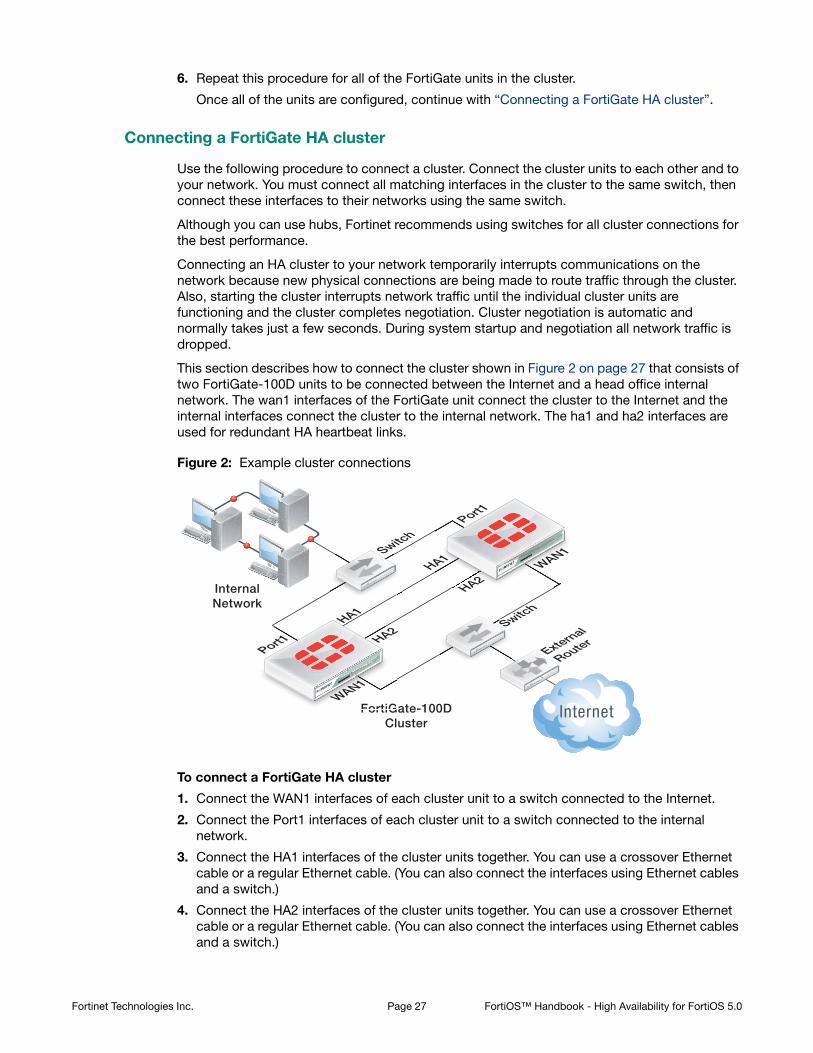
This section describes how to connect the cluster shown in Figure 2 on page 27 that consists of two FortiGate-100D units to be connected between the Internet and a head office internal network. The wan1 interfaces of the FortiGate unit connect the cluster to the Internet and the internal interfaces connect the cluster to the internal network. The ha1 and ha2 interfaces are used for redundant HA heartbeat links.
Figure 2: Example cluster connections
To connect a FortiGate HA cluster
1. Connect the WAN1 interfaces of each cluster unit to a switch connected to the Internet.
2. Connect the Port1 interfaces of each cluster unit to a switch connected to the internal network.
3. Connect the HA1 interfaces of the cluster units together. You can use a crossover Ethernet cable or a regular Ethernet cable. (You can also connect the interfaces using Ethernet cables and a switch.)
4. Connect the HA2 interfaces of the cluster units together. You can use a crossover Ethernet cable or a regular Ethernet cable. (You can also connect the interfaces using Ethernet cables and a switch.)
InternalNetwork
FortiGate-100DCluster
FortiG
External
Router
Switch
Switch
Port1
WAN1
WAN1
Port1
HA1
HA1
HA2
HA2
Sw
S
Fortinet Technologies Inc. Page 27 FortiOS™ Handbook - High Availability for FortiOS 5.0

5. Power on both of the FortiGate units.
As the cluster units start, they negotiate to choose the primary unit and the subordinate unit. This negotiation occurs with no user intervention and normally just takes a few seconds.
At least one heartbeat interface should be connected together for the cluster to operate.
Do not use a switch port for the HA heartbeat traffic. This configuration is not supported.
You could use one switch to connect all four heartbeat interfaces. However, this is not recommended because if the switch fails both heartbeat interfaces will become disconnected.
For more information about heartbeat interfaces, see “HA heartbeat and communication between cluster units” on page 193.
6. You can now configure the cluster as if it is a single FortiGate unit.
Active-passive and active-active HA
The first decision to make when configuring FortiGate HA is whether to choose active-passive or active-active HA mode. To configure the HA mode, go to System > Config > HA and set Mode to Active-Passive or Active-Active.
From the CLI enter the following command to set the HA mode to active-passive:
config system ha
set mode a-p
end
To form a cluster, all cluster units must be set to the same mode. You can also change the mode after the cluster is up and running. Changing the mode of a functioning cluster causes a slight delay while the cluster renegotiates to operate in the new mode and possibly select a new primary unit.
Active-passive HA (failover protection)
An active-passive (A-P) HA cluster provides hot standby failover protection. An active-passive cluster consists of a primary unit that processes communication sessions, and one or more subordinate units. The subordinate units are connected to the network and to the primary unit but do not process communication sessions. Instead, the subordinate units run in a standby state. In this standby state, the configuration of the subordinate units is synchronized with the configuration of the primary unit and the subordinate units monitor the status of the primary unit.
Active-passive HA provides transparent device failover among cluster units. If a cluster unit fails, another immediately take its place. See “Device failover” on page 192.
Active-passive HA also provides transparent link failover among cluster units. If a cluster unit interface fails or is disconnected, this cluster unit updates the link state database and the cluster negotiates and may select a new primary unit. See “Link failover (port monitoring or interface monitoring)” on page 219 for more information.
If session failover (also called session pickup) is enabled, active-passive HA provides session failover for some communication sessions. See “Session failover (session pick-up)” on page 231 for information about session failover and its limitations.
Fortinet Technologies Inc. Page 28 FortiOS™ Handbook - High Availability for FortiOS 5.0

The following example shows how to configure a FortiGate unit for active-passive HA operation. You would enter the exact same commands on every FortiGate unit in the cluster.
config system ha
set mode a-p
set group-name myname
set password HApass
end
Active-active HA (load balancing and failover protection)
Active-active (A-A) HA load balances resource-intensive content inspection processing among all cluster units. Content inspection processing applies protocol recognition, virus scanning, IPS, web filtering, email filtering, data leak prevention (DLP), application control, and VoIP content scanning and protection to HTTP, HTTPS, FTP, IMAP, IMAPS, POP3, POP3S, SMTP, SMTPS, IM, NNTP, SIP, SIMPLE, and SCCP sessions accepted by security policies. By load balancing this resource-intensive processing among all cluster units, an active-active HA cluster may provide better content inspection performance than a standalone FortiGate unit. Other features enabled in security policies such as Endpoint security, traffic shaping, user authentication, and device identification have no effect active-active load balancing.
Normally, sessions that don’t include content inspection are not load balanced and are processed by the primary unit. You can configure active-active HA to load balance additional sessions. For more information see “Load balancing UTM sessions, TCP sessions, and UDP sessions” on page 248.
An active-active HA cluster consists of a primary unit that receives all communication sessions and load balances them among the primary unit and all of the subordinate units. In an active-active cluster the subordinate units are also considered active since they also process content processing sessions. In all other ways active-active HA operates the same as active-passive HA.
The following example shows how to configure a FortiGate unit for active-active HA operation. You would enter the exact same commands on every FortiGate unit in the cluster.
config system ha
set mode a-a
set group-name myname
set password HApass
end
Identifying the cluster and cluster units
You can use the cluster group name, group id, and password to identify a cluster and distinguish one cluster from another. If you have more than one cluster on the same network, each cluster must have a different group name, group id, and password.
Group name
Use the group name to identify the cluster. The maximum length of the group name is 32 characters. The group name must be the same for all cluster units before the cluster units can form a cluster. After a cluster is operating, you can change the group name. The group name change is synchronized to all cluster units.
The default group name is FGT-HA. The group name appears on the FortiGate dashboard of a functioning cluster as the Cluster Name.
Fortinet Technologies Inc. Page 29 FortiOS™ Handbook - High Availability for FortiOS 5.0

To change the group name from the web-based manager go to Config > System > HA and change the Group Name.
Enter the following CLI command to change the group name to Cluster_name:
config system ha
set group-name Cluster_name
end
Password
Use the password to identify the cluster. You should always change the password when configuring a cluster. The password must be the same for all FortiGate units before they can form a cluster. When the cluster is operating you can change the password, if required. Two clusters on the same network cannot have the same password.
To change the password from the web-based manager go to Config > System > HA and change the Password.
Enter the following CLI command to change the password to ha_pwd:
config system ha
set password ha_pwd
end
Group ID
Similar to the group name, the group ID is also identifies the cluster. In most cases you do not have to change the group ID. However, you should change the group ID if you have more than one cluster on the same network. All members of the HA cluster must have the same group ID. The group ID is a number from 0 to 255.
Changing the group ID changes the cluster virtual MAC address. See “Cluster virtual MAC addresses” on page 200.
Enter the following CLI command to change the group ID to 10:
config system ha
set group-id 10
end
Device failover, link failover, and session failover
The FGCP provides transparent device and link failover. You can also enable session pickup to provide session failover. A failover can be caused by a hardware failure, a software failure, or something as simple as a network cable being disconnected causing a link failover. When a failover occurs, the cluster detects and recognizes the failure and takes steps to respond so that the network can continue to operate without interruption. The internal operation of the cluster changes, but network components outside of the cluster notice little or no change.
If a failover occurs, the cluster also records log messages about the event and can be configured to send log messages to a syslog server and to a FortiAnalyzer unit. The cluster can also send SNMP traps and alert email messages. These alerts can notify network administrators of the failover and may contain information that the network administrators can use to find and fix the problem that caused the failure.
For a complete description of device failover, link failover, and session failover, how clusters support these types of failover, and how FortiGate HA clusters compensate for a failure to maintain network traffic flow see “HA and failover protection” on page 190.
Fortinet Technologies Inc. Page 30 FortiOS™ Handbook - High Availability for FortiOS 5.0

Primary unit selection
Once FortiGate units recognize that they can form a cluster, the cluster units negotiate to select a primary unit. Primary unit selection occurs automatically based on the criteria shown in Figure 3. After the cluster selects the primary unit, all of the remaining cluster units become subordinate units.
Negotiation and primary unit selection also takes place if a primary unit fails (device failover) or if a monitored interface fails or is disconnected (link failover). During a device or link failover, the cluster renegotiates to select a new primary unit also using the criteria shown in Figure 3.
Figure 3: Selecting the primary unit
For many basic HA configurations primary unit selection simply selects the cluster unit with the highest serial number to become the primary unit. A basic HA configuration involves setting the HA mode to active-passive or active-active and configuring the cluster group name and password. Using this configuration, the cluster unit with the highest serial number becomes the primary unit because primary unit selection disregards connected monitored interfaces (because interface monitoring is not configured), the age of the cluster units would usually always be the same, and all units would have the same device priority.
Using the serial number is a convenient way to differentiate cluster units; so basing primary unit selection on the serial number is predictable and easy to understand and interpret. Also the cluster unit with the highest serial number would usually be the newest FortiGate unit with the most recent hardware version. In many cases you may not need active control over primary unit selection, so basic primary unit selection based on serial number is sufficient.
Primary Unit Subordinate Unit
Less
Less
Less
Less
Greater
Begin Negotiation
Greater
Greater
Equal
Equal
Equal
Greater
ConnectedMonitoredInterfaces
Age
Device Priority
Serial Number
Priimmary Unit Subboorrdddddddiinate U
Fortinet Technologies Inc. Page 31 FortiOS™ Handbook - High Availability for FortiOS 5.0

In some situations you may want have control over which cluster unit becomes the primary unit. You can control primary unit selection by setting the device priority of one cluster unit to be higher than the device priority of all other cluster units. If you change one or more device priorities, during negotiation, the cluster unit with the highest device priority becomes the primary unit. As shown in Figure 3 the FGCP selects the primary unit based on device priority before serial number. For more information about how to use device priorities, see “Primary unit selection and device priority” on page 36.
The only other way that you can influence primary unit selection is by configuring interface monitoring (also called port monitoring). Using interface monitoring you can make sure that cluster units with failed or disconnected monitored interfaces cannot become the primary unit. See “Primary unit selection and monitored interfaces” on page 32.
Finally, the age of a cluster unit is determined by a number of operating factors. Normally the age of all cluster units is the same so normally age has no effect on primary unit selection. Age does affect primary unit selection after a monitored interface failure. For more information about age, see “Primary unit selection and age” on page 33.
This section describes:
• Primary unit selection and monitored interfaces
• Primary unit selection and age
• Primary unit selection and device priority
• Primary unit selection and the FortiGate unit serial number
• Points to remember about primary unit selection
Primary unit selection and monitored interfaces
If you have configured interface monitoring the cluster unit with the highest number of monitored interfaces that are connected to networks becomes the primary unit. Put another way, the cluster unit with the highest number of failed or disconnected monitored interfaces cannot become the primary unit.
Normally, when a cluster starts up, all monitored interfaces of all cluster units are connected and functioning normally. So monitored interfaces do not usually affect primary unit selection when the cluster first starts.
A cluster always renegotiates when a monitored interface fails or is disconnected (called link failover). A cluster also always renegotiates when a failed or disconnected monitored interface is restored.
If a primary unit monitored interface fails or is disconnected, the cluster renegotiates and if this is the only failed or disconnected monitored interface the cluster selects a new primary unit.
If a subordinate unit monitored interface fails or is disconnected, the cluster also renegotiates but will not necessarily select a new primary unit. However, the subordinate unit with the failed or disconnected monitored interface cannot become the primary unit.
Multiple monitored interfaces can fail or become disconnected on more than one cluster unit. Each time a monitored interface is disconnected or fails, the cluster negotiates to select the cluster unit with the most connected and operating monitored interfaces to become the primary unit. In fact, the intent of the link failover feature is just this, to make sure that the primary unit is always the cluster unit with the most connected and operating monitored interfaces. For information about monitored interfaces and link failover see “Link failover (port monitoring or interface monitoring)” on page 219.
Fortinet Technologies Inc. Page 32 FortiOS™ Handbook - High Availability for FortiOS 5.0

Primary unit selection and age
The cluster unit with the highest age value becomes the primary unit. The age of a cluster unit is the amount of time since a monitored interface failed or is disconnected. Age is also reset when a cluster unit starts (boots up). So, when all cluster units start up at about the same time, they all have the same age. Age does not affect primary unit selection when all cluster units start up at the same time. Age also takes precedence over priority for primary unit selection.
If a link failure of a monitored interface occurs, the age value for the cluster unit that experiences the link failure is reset. So, the cluster unit that experienced the link failure also has a lower age value than the other cluster units. This reduced age does not effect primary unit selection because the number of link failures takes precedence over the age.
If the failed monitored interface is restored the cluster unit that had the failed monitored interface cannot become the primary unit because its age is still lower than the age of the other cluster units.
In most cases, the way that age is handled by the cluster reduces the number of times the cluster selects a new primary unit, which results in a more stable cluster since selecting a new primary unit has the potential to disrupt traffic.
Cluster age difference margin (grace period)
In any cluster, some of the cluster units may take longer to start up than others. This startup time difference can happen as a result of a number of issues and does not affect the normal operation of the cluster. To make sure that cluster units that start slower can still become primary units, by default the FGCP ignores age differences of up to 5 minutes (300 seconds).
In most cases, during normal operation this age difference margin or grace period helps clusters function as expected. However, the age difference margin can result in some unexpected behavior in some cases:
• During a cluster firmware upgrade with uninterruptible-upgrade enabled (the default configuration) the cluster should not select a new primary unit after the firmware of all cluster units has been updated. But since the age difference of the cluster units is most likely less than 300 seconds, age is not used to affect primary unit selection and the cluster may select a new primary unit. See “Upgrading cluster firmware” on page 174 for more information.
• During failover testing where cluster units are failed over repeatedly the age difference between the cluster units will most likely be less than 5 minutes. During normal operation, if a failover occurs, when the failed unit rejoins the cluster its age will be very different from the age of the still operating cluster units so the cluster will not select a new primary unit. However, if a unit fails and is restored in a very short time the age difference may be less than 5 minutes. As a result the cluster may select a new primary unit during some failover testing scenarios.
Changing the cluster age difference margin
You can change the cluster age difference margin using the following command:
config system ha
set ha-uptime-diff-margin 60
end
This command sets the cluster age difference margin to 60 seconds (1 minute). The age difference margin range 1 to 65535 seconds. The default is 300 seconds.
You may want to reduce the margin if during failover testing you don’t want to wait the default age difference margin of 5 minutes. You may also want to reduce the margin to allow uninterruptible upgrades to work. See “Upgrading cluster firmware” on page 174.
Fortinet Technologies Inc. Page 33 FortiOS™ Handbook - High Availability for FortiOS 5.0

You may want to increase the age margin if cluster unit startup time differences are larger than 5 minutes.
Displaying cluster unit age differences
You can use the CLI command diagnose sys ha dump-by all-vcluster to display the age difference of the units in a cluster. This command also displays information about a number of HA-related parameters for each cluster unit. You can enter the command from the primary unit CLI or you can enter the command from a subordinate unit after using execute ha manage to log into a subordinate unit CLI. The information displayed by the command is relative to the unit that you enter the command from.
For example, a cluster of two FortiGate-5001C units with no changes to the default HA configuration except to enable port monitoring for port1. Entering the diagnose sys ha dump-by all-vcluster command from the primary unit CLI displays information similar to the following:
diagnose sys ha dump-by all-vcluster
HA information.
vcluster id=1, nventry=2, state=work, digest=4.a5.60.11.cf.d4...
ventry idx=0,id=1,FG-5KC3E13800084,prio=128,-50,claimed=0, override=0,flag=1,time=0,mon=0
mondev=port1,50
ventry idx=1,id=1,FG-5KC3E13800046,prio=128,-50,claimed=0, override=0,flag=0,time=-98,mon=0
The command displays one ventry line for each cluster unit. The first ventry in the example contains information for the cluster unit that you are logged into (usually the primary unit). The other ventry lines contain information for the other units in the cluster (in the example there is only one other cluster unit). The command also includes a mondev entry that displays the interface monitoring configuration.
The time field is always 0 for the unit that you are logged into. The time field for the other cluster unit is the age difference between the unit that you are logged into and the other cluster unit. The age difference is in the form seconds/10.
In the example, the age of the primary unit is 12.9 seconds more than the age of the subordinate unit. The age difference is less than 5 minutes (less than 300 seconds) so age has no affect on primary unit selection. The cluster selected the unit with the highest serial number to be the primary unit.
If you use execute ha manage 1 to log into the subordinate unit CLI and enter diagnose sys ha dump 1 you get results similar to the following:
diagnose sys ha dump-by all-vcluster
HA information.
vcluster id=1, nventry=2, state=standy, digest=4.a5.60.11.cf.d4...
ventry idx=1,id=1,FG-5KC3E13800046,prio=128,-50,claimed=0, override=0,flag=1,time=0,mon=0
mondev=port1,50
ventry idx=0,id=1,FG-5KC3E13800084,prio=128,-50,claimed=1, override=0,flag=0,time=98,mon=0
The time for the primary unit is 98, indicating that age of the subordinate unit age is 9.8 seconds higher than the primary unit age.
Fortinet Technologies Inc. Page 34 FortiOS™ Handbook - High Availability for FortiOS 5.0

If port1 (the monitored interface) of the primary unit is disconnected, the cluster renegotiates and the former subordinate unit becomes the primary unit. When you log into the new primary unit CLI and enter diagnose sys ha dump-by all-vcluster you could get results similar to the following:
diagnose sys ha dump-by all-vcluster
HA information.
vcluster id=1, nventry=2, state=work, digest=3.f8.d1.63.4d.d2...
ventry idx=0,id=1,FG-5KC3E13800046,prio=128,0,claimed=0, override=0,flag=1,time=0,mon=0
mondev=port1,50
ventry idx=1,id=1,FG-5KC3E13800084,prio=128,-50,claimed=0, override=0,flag=0,time=1362,mon=0
The command results show that the age of the new primary unit is 136.2 seconds higher than the age of the new subordinate unit.
If port1 of the former primary unit is reconnected the cluster will once again make this the primary unit because the age difference will still be less than 300 seconds. When you log into the primary unit CLI and enter diagnose sys ha dump-by all-vcluster you get results similar to the following:
diagnose sys ha dump-by all-vcluster
HA information.
vcluster id=1, nventry=2, state=work, digest=4.a5.60.11.cf.d4...
ventry idx=0,id=1,FG-5KC3E13800084,prio=128,0,claimed=0, override=0,flag=1,time=0,mon=0
mondev=port1,50
ventry idx=1,id=1,FG-5KC3E13800046,prio=128,0,claimed=0, override=0,flag=0,time=-1362,mon=0
Resetting the age of all cluster units
In some cases, age differences among cluster units can result in the wrong cluster unit or the wrong virtual cluster becoming the primary unit. For example, if a cluster unit set to a high priority reboots, that unit will have a lower age than other cluster units when it rejoins the cluster. Since age takes precedence over priority, the priority of this cluster unit will not be a factor in primary unit selection.
This problem also affects virtual cluster VDOM partitioning in a similar way. After a reboot of one of the units in a virtual cluster configuration, traffic for all VDOMs could continue to be processed by the cluster unit that did not reboot. This can happen because the age of both virtual clusters on the unit that did not reboot is greater that the age of both virtual clusters on the unit that rebooted.
One way to resolve this issue is to reboot all of the cluster units at the same time so that the age of all of the cluster units is reset. However, rebooting cluster units may interrupt or at least slow down traffic. If you would rather not reboot all of the cluster units you can instead use the following command to reset the age of individual cluster units.
diagnose sys ha reset-uptime
Fortinet Technologies Inc. Page 35 FortiOS™ Handbook - High Availability for FortiOS 5.0
This command resets the age of a unit back to zero so that if no other unit in the cluster was reset at the same time, it will now have the lowest age. You would use this command to reset the age of the cluster unit that is currently the primary unit. Since it will have the lowest age, the other unit in the cluster will have the highest age and can then become the primary unit.
Primary unit selection and device priority
A cluster unit with the highest device priority becomes the primary unit when the cluster starts up or renegotiates. By default, the device priority for all cluster units is 128. You can change the device priority to control which FortiGate unit becomes the primary unit during cluster negotiation. All other factors that influence primary unit selection either cannot be configured (age and serial number) or are synchronized among all cluster units (interface monitoring). You can set a different device priority for each cluster unit. During negotiation, if all monitored interfaces are connected, and all cluster units enter the cluster at the same time (or have the same age), the cluster with the highest device priority becomes the primary unit.
A higher device priority does not affect primary unit selection for a cluster unit with the most failed monitored interfaces or with an age that is higher than all other cluster units because failed monitored interfaces and age are used to select a primary unit before device priority.
Increasing the device priority of a cluster unit does not always guarantee that this cluster unit will become the primary unit. During cluster operation, an event that may affect primary unit selection may not always result in the cluster renegotiating. For example, when a unit joins a functioning cluster, the cluster will not renegotiate. So if a unit with a higher device priority joins a cluster the new unit becomes a subordinate unit until the cluster renegotiates.
Controlling primary unit selection by changing the device priority
You set a different device priority for each cluster unit to control the order in which cluster units become the primary unit when the primary unit fails.
To change the device priority from the web-based manager go to Config > System > HA and change the Device Priority.
Enter the following CLI command to change the device priority to 200:
config system ha
set priority 200
end
The device priority is not synchronized among cluster units. In a functioning cluster you can change the device priority of any unit in the cluster. Whenever you change the device priority of a cluster unit, when the cluster negotiates, the unit with the highest device priority becomes the primary unit.
The diagnose sys ha reset-uptime command should only be used as a temporary solution. The command resets the HA age internally and does not affect the up time displayed for cluster units using the diagnose sys ha dump-by all-vcluster command or the up time displayed on the Dashboard or cluster members list. To make sure the actual up time for cluster units is the same as the HA age you should reboot the cluster units during a maintenance window.
Enabling the override HA CLI keyword makes changes in device priority more effective by causing the cluster to negotiate more often to make sure that the primary unit is always the unit with the highest device priority. For more information about override, see “HA override” on page 38.
Fortinet Technologies Inc. Page 36 FortiOS™ Handbook - High Availability for FortiOS 5.0

The following example shows how to change the device priority of a subordinate unit to 255 so that this subordinate unit becomes the primary unit. You can change the device priority of a subordinate unit by going to Config > System > HA and selecting the Edit icon for the subordinate unit. Or from the CLI you can use the execute ha manage 0 command to connect to the highest priority subordinate unit. After you enter the following commands the cluster renegotiates and selects a new primary unit.
execute ha manage 1
config system ha
set priority 255
end
If you have three units in a cluster you can set the device priorities as shown in Table 1. When the cluster starts up, cluster unit A becomes the primary unit because it has the highest device priority. If unit A fails, unit B becomes the primary unit because unit B has a higher device priority than unit C.
When configuring HA you do not have to change the device priority of any of the cluster units. If all cluster units have the same device priority, when the cluster first starts up the FGCP negotiates to select the cluster unit with the highest serial number to be the primary unit. Clusters also function normally if all units have the same device priority.
You can change the device priority if you want to control the roles that individual units play in the cluster. For example, if you want the same unit to always become the primary unit, set this unit device priority higher than the device priority of other cluster units. Also, if you want a cluster unit to always become a subordinate unit, set this cluster unit device priority lower than the device priority of other cluster units.
If you have a cluster of three units you can set a different priority for each unit to control which unit becomes the primary unit when all three cluster units and functioning and which will be the primary unit when two cluster units are functioning.
The device priority range is 0 to 255. The default device priority is 128.
If you are configuring a virtual cluster, if you have added virtual domains to both virtual clusters, you can set the device priority that the cluster unit has in virtual cluster 1 and virtual cluster 2. If a FortiGate unit has different device priorities in virtual cluster 1 and virtual cluster 2, the FortiGate unit may be the primary unit in one virtual cluster and the subordinate unit in the other. For more information, see “Virtual clustering and load balancing or VDOM partitioning” on page 118.
Primary unit selection and the FortiGate unit serial number
The cluster unit with the highest serial number is more likely to become the primary unit. When first configuring FortiGate units to be added to a cluster, if you do not change the device priority of any cluster unit, then the cluster unit with the highest serial number always becomes the primary unit.
Table 1: Example device priorities for a cluster of three FortiGate units
Cluster unit Device priority
A 200
B 100
C 50
Fortinet Technologies Inc. Page 37 FortiOS™ Handbook - High Availability for FortiOS 5.0

Age does take precedence over serial number, so if a cluster unit takes longer to join a cluster for some reason (for example if one cluster unit is powered on after the others), that cluster unit will not become the primary unit because the other units have been in the cluster longer.
Device priority and failed monitored interfaces also take precedence over serial number. A higher device priority means a higher priority. So if you set the device priority of one unit higher or if a monitored interface fails, the cluster will not use the FortiGate serial number to select the primary unit.
Points to remember about primary unit selection
Some points to remember about primary unit selection:
• The FGCP compares primary unit selection criteria in the following order: Failed Monitored interfaces > Age > Device Priority > Serial number. The selection process stops at the first criteria that selects one cluster unit.
• Negotiation and primary unit selection is triggered if a cluster unit fails or if a monitored interface fails.
• If the HA age difference is more than 5 minutes (300 seconds), the cluster unit that is operating longer becomes the primary unit.
• If HA age difference is less than 5 minutes (300 seconds), the device priority and FortiGate serial number selects the cluster unit to become the primary unit.
• Every time a monitored interface fails the HA age of the cluster unit is reset to 0.
• Every time a cluster unit restarts the HA age of the cluster unit is reset to 0.
HA override
The HA override CLI keyword is disabled by default. When override is disabled a cluster may not always renegotiate when an event occurs that affects primary unit selection. For example, when override is disabled a cluster will not renegotiate when you change a cluster unit device priority or when you add a new cluster unit to a cluster. This is true even if the unit added to the cluster has a higher device priority than any other unit in the cluster. Also, when override is disabled a cluster does not negotiate if the new unit added to the cluster has a failed or disconnected monitored interface.
In most cases you should keep override disabled to reduce how often the cluster negotiates. Frequent negotiations may cause frequent traffic interruptions.
However, if you want to make sure that the same cluster unit always operates as the primary unit and if you are less concerned about frequent cluster negotiation you can set its device priority higher than other cluster units and enable override.
To enable override, connect to each cluster unit CLI (using the execute ha manage command) and use the config system ha CLI command to enable override.
For override to be effective, you must also set the device priority highest on the cluster unit that you want to always be the primary unit. To increase the device priority, from the CLI use the config system ha command and increase the value of the priority keyword to a number higher than the default priority of 128.
For a virtual cluster configuration, override is enabled by default for both virtual clusters when you enable virtual cluster 2. For more information, see “Virtual clustering and HA override” on page 118.
Fortinet Technologies Inc. Page 38 FortiOS™ Handbook - High Availability for FortiOS 5.0

You can also increase the device priority from the web-based manager by going to System > Config > HA. To increase the device priority of the primary unit select edit for the primary or subordinate unit and set the Device Priority to a number higher than 128.
With override enabled, the primary unit with the highest device priority will always become the primary unit. Whenever an event occurs that may affect primary unit selection, the cluster negotiates. For example, when override is enabled a cluster renegotiates when you change the device priority of any cluster unit or when you add a new unit to a cluster.
This section also describes:
• Override and primary unit selection
• Controlling primary unit selection using device priority and override
• Points to remember about primary unit selection when override is enabled
• Configuration changes can be lost if override is enabled
• Override and disconnecting a unit from a cluster
Override and primary unit selection
Enabling override changes the order of primary unit selection. As shown in Figure 4 if override is enabled, primary unit selection considers device priority before age and serial number. This means that if you set the device priority higher on one cluster unit, with override enabled this cluster unit becomes the primary unit even if its age and serial number are lower than other cluster units.
Similar to when override is disabled, when override is enabled primary unit selection checks for connected monitored interfaces first. So if interface monitoring is enabled, the cluster unit with the most disconnected monitored interfaces cannot become the primary unit, even of the unit has the highest device priority.
If all monitored interfaces are connected (or interface monitoring is not enabled) and the device priority of all cluster units is the same then age and serial number affect primary unit selection.
The override setting and device priority value are not synchronized to all cluster units. You must enable override and adjust device priority manually and separately for each cluster unit.
Fortinet Technologies Inc. Page 39 FortiOS™ Handbook - High Availability for FortiOS 5.0

Figure 4: Selecting the primary unit with override enabled
Controlling primary unit selection using device priority and override
To configure one cluster unit to always become the primary unit you should set its device priority to be higher than the device priorities of the other cluster units and you should enable override on all cluster units.
Using this configuration, when the cluster is operating normally the primary unit is always the unit with the highest device priority. If the primary unit fails the cluster renegotiates to select another cluster unit to be the primary unit. If the failed primary unit recovers, starts up again and rejoins the cluster, because override is enabled, the cluster renegotiates. Because the restarted primary unit has the highest device priority it once again becomes the primary unit.
In the same situation with override disabled, because the age of the failed primary unit is lower than the age of the other cluster units, when the failed primary unit rejoins the cluster it does not become the primary unit. Instead, even though the failed primary unit may have the highest device priority it becomes a subordinate unit because its age is lower than the age of all the other cluster units.
Primary Unit Subordinate Unit
Less
Less
Less
Less
Greater
Begin Negotiation
Greater
Greater
Equal
Equal
Equal
Greater
ConnectedMonitoredInterfaces
Device Priority
Age
Serial Number
Primmaar Unit S boorddddddinate Un
Fortinet Technologies Inc. Page 40 FortiOS™ Handbook - High Availability for FortiOS 5.0

Points to remember about primary unit selection when override is enabled
Some points to remember about primary unit selection when override is enabled:
• The FGCP compares primary unit selection criteria in the following order: Failed Monitored Interfaces > Device Priority > Age > Serial number. The selection process stops at the first criteria that selects one cluster unit.
• Negotiation and primary unit selection is triggered whenever an event occurs which may affect primary unit selection. For example negotiation occurs, when you change the device priority, when you add a new unit to a cluster, if a cluster unit fails, or if a monitored interface fails.
• Device priority is considered before age. Otherwise age is handled the same when override is enabled.
Configuration changes can be lost if override is enabled
In some cases, when override is enabled and you make configuration changes to an HA cluster these changes can be lost. For example, consider the following sequence:
1. A cluster of two FortiGate units is operating with override enabled.
• FGT-A: Primary unit with device priority 200 and with override enabled
• FGT-B: Subordinate unit with device priority 100 and with override disabled
• If both units are operating, FGT-A always becomes the primary unit because FGT-A has the highest device priority.
2. FGT-A fails and FGT-B becomes the new primary unit.
3. The administrator makes configuration changes to the cluster.
The configuration changes are made to FGT-B because FGT-B is operating as the primary unit. These configuration changes are not synchronized to FGT-A because FGT-A is not operating.
4. FGT-A is restored and starts up again.
5. The cluster renegotiates and FGT-A becomes the new primary unit.
6. The cluster recognizes that the configurations of FGT-A and FGT-B are not the same.
7. The configuration of FGT-A is synchronized to FGT-B.
The configuration is always synchronized from the primary unit to the subordinate units.
8. The cluster is now operating with the same configuration as FGT-A. The configuration changes made to FGT-B have been lost.
The solution
When override is enabled, you can prevent configuration changes from being lost by doing the following:
• Verify that all cluster units are operating before making configuration changes (from the web-based manager go to System > Config > HA to view the cluster members list or from the FortiOS CLI enter get system ha status).
• Make sure the device priority of the primary unit is set higher than the device priorities of all other cluster units before making configuration changes.
• Disable override either permanently or until all configuration changes have been made and synchronized to all cluster units.
Fortinet Technologies Inc. Page 41 FortiOS™ Handbook - High Availability for FortiOS 5.0

Override and disconnecting a unit from a cluster
A similar scenario to that described in “Configuration changes can be lost if override is enabled” may occur when override is enabled and you use the Disconnect from Cluster option from the web-based manager or the execute ha disconnect command from the CLI to disconnect a cluster unit from a cluster.
Configuration changes made to the cluster can be lost when you reconnect the disconnected unit to the cluster. You should make sure that the device priority of the disconnected unit is lower than the device priority of the current primary unit. Otherwise, when the disconnected unit joins the cluster, if override is enabled, the cluster renegotiates and the disconnected unit may become the primary unit. If this happens, the configuration of the disconnected unit is synchronized to all other cluster units and any configuration changes made between when the unit was disconnected and reconnected are lost.
FortiGate HA compatibility with PPPoE and DHCP
FortiGate HA is not compatible with PPP protocols such as PPPoE. FortiGate HA is also not compatible with DHCP. If one or more FortiGate unit interfaces is dynamically configured using DHCP or PPPoE you cannot switch to operate in HA mode. Also, you cannot switch to operate in HA mode if one or more FortiGate unit interfaces is configured as a PPTP or L2TP client.
You can configure a cluster to act as a DHCP server or a DHCP relay agent. In both active-passive and active-active clusters DHCP relay sessions are always handled by the primary unit. It is possible that a DHCP relay session could be interrupted by a failover. If this occurs the DHCP relay session is not resumed after the failover and the DHCP client may have to repeat the DHCP request.
When a cluster is operating as a DHCP server the primary unit responds to all DHCP requests and maintains the DHCP server address lease database. The cluster also dynamically synchronizes the DHCP server address lease database to the subordinate units. If a failover occurs, the new primary unit will have an up-to-date DHCP server address lease database. Synchronizing the DHCP address lease database prevents the new primary unit from responding incorrectly to new DHCP requests after a failover.
Also, it is possible that when FortiGate units first negotiate to form a cluster that a unit that ends up as a subordinate unit in the cluster will have information in its DHCP address lease database that the cluster unit operating as the primary unit does note have. This can happen if a FortiGate unit responds to DHCP requests while operating as a standalone unit and then when the cluster is formed this unit becomes a subordinate unit. Because of this possibility, after a cluster is formed the DHCP address lease databases of all of the cluster units are merged into one database which is then synchronized to all cluster units.
Configuring an interface for DHCP or PPPoE is only supported in NAT/Route mode. So, usually when configuring HA in Transparent mode an interface being configured for DHCP or PPPoE should not affect HA operation. However, in some cases you may not be able to enable HA if you had configured an interface for DHCP or PPPoE before switching to Transparent mode. So, if you are blocked from operating a Transparent mode FortiGate unit in HA and cannot find another reason for the problem, try switching the FortiGate unit back to NAT/Route mode and setting all interface modes to static before switching to Transparent mode and enabling HA. You could also enable HA before switching to Transparent mode.
Fortinet Technologies Inc. Page 42 FortiOS™ Handbook - High Availability for FortiOS 5.0

HA and distributed clustering
The FGCP supports widely separated cluster units installed in different physical locations. Distributed clusters can have cluster units in different rooms in the same building, different buildings in the same location, or even different geographical sites such as different cities, countries or continents.
Just like any cluster, distributed clusters require heartbeat communication between cluster units. In a distributed cluster this heartbeat communication can take place over the Internet or over other transmission methods including satellite linkups.
Because of the possible distance it may take a relatively long time for heartbeat packets to be transmitted between cluster units. To support a distributed cluster you may need to increase the heartbeat interval so that the cluster expects extra time between heartbeat packets. For information about changing the heartbeat interval and other heartbeat related settings, see “Modifying heartbeat timing” on page 198.
Hard disk configuration and HA
If your cluster units include hard disks, all cluster units must have identical hard disk configurations. This means each cluster unit must have same number of hard disks (including AMC and FortiGate Storage Module (FSM) hard disks) and also means that matching hard disks in each cluster unit must be the same size, have the same hard disk format, and have the same number of partitions.
In most cases the default hard disk configuration of the cluster units will be compatible. However, a hard disk formatted by an older FortiGate firmware version may not be compatible with a hard disk formatted by a more recent firmware version. Problems may also arise if you have used the execute scsi-dev command to add or change hard disk protections.
If a cluster unit CLI displays hard disk compatibility messages, you may need to use the execute scsi-dev delete command to delete partitions. You can also use the execute formatlogdisk command to reformat hard disks. In some cases after deleting all partitions and reformatting the hard disks, you may still see hard disk incompatibility messages. If this happens, contact Fortinet Customer Support for assistance.
FGCP high availability best practices
Fortinet suggests the following practices related to high availability:
• Use Active-Active HA to distribute TCP and UTM sessions among multiple cluster units. An active-active cluster may have higher throughput than a standalone FortiGate unit or than an active-passive cluster.
• Use a different host name on each FortiGate unit when configuring an HA cluster. Fewer steps are required to add host names to each cluster unit before configuring HA and forming a cluster.
• Consider adding an Alias to the interfaces used for the HA heartbeat so that you always get a reminder about what these interfaces are being used for.
• Enabling load-balance-all can increase device and network load since more traffic is load-balanced. This may be appropriate for use in a deployment using the firewall capabilities of the FortiGate unit and IPS but no other content inspection. See “Load balancing UTM sessions, TCP sessions, and UDP sessions” on page 248.
• An advantage of using session pickup is that non-content inspection sessions will be picked up by the new primary unit after a failover. The disadvantage is that the cluster generates more heartbeat traffic to support session pickup as a larger portion of the session table must
Fortinet Technologies Inc. Page 43 FortiOS™ Handbook - High Availability for FortiOS 5.0

be synchronized. Session pickup should be configured only when required and is not recommended for use with SOHO FortiGate models. Session pickup should only be used if the primary heartbeat link is dedicated (otherwise the additional HA heartbeat traffic could affect network performance). See “Session failover (session pick-up)” on page 231.
• If session pickup is not selected, after a device or link failover all sessions are briefly interrupted and must be re-established at the application level after the cluster renegotiates. For example, after a failover, users browsing the web can just refresh their browsers to resume browsing. Users downloading large files may have to restart their download after a failover. Other protocols may experience data loss and some protocols may require sessions to be manually restarted. For example, a user downloading files with FTP may have to either restart downloads or restart their FTP client.
• If you need to enable session pickup, consider enabling session pickup delay to improve performance by reducing the number of sessions that are synchronized. If possible, also consider enabling session synchronization or multiple FortiGate Interfaces. See “Improving session synchronization performance” on page 232 for more information.
• To avoid unpredictable results, when you connect a switch to multiple redundant or aggregate interfaces in an active-passive cluster you should configure separate redundant or aggregate interfaces on the switch; one for each cluster unit. See “HA MAC addresses and 802.3ad aggregation” on page 88.
• Use SNMP, syslog, or email alerts to monitor a cluster for failover messages. Alert messages about cluster failovers may help find and diagnose network problems quickly and efficiently. See “Operating a cluster” on page 152.
Heartbeat interfaces
Fortinet suggests the following practices related to heartbeat interfaces:
• Isolate heartbeat interfaces from user networks. Heartbeat packets contain sensitive cluster configuration information and can consume a considerable amount of network bandwidth. If the cluster consists of two FortiGate units, connect the heartbeat interfaces directly using a crossover cable or a regular Ethernet cable. For clusters with more than two units, connect heartbeat interfaces to a separate switch that is not connected to any network.
• If heartbeat traffic cannot be isolated from user networks, enable heartbeat message encryption and authentication to protect cluster information. See “Enabling or disabling HA heartbeat encryption and authentication” on page 199.
• Configure and connect redundant heartbeat interfaces so that if one heartbeat interface fails or becomes disconnected, HA heartbeat traffic can continue to be transmitted using the backup heartbeat interface. If heartbeat communication fails, all cluster members will think they are the primary unit resulting in multiple devices on the network with the same IP addresses and MAC addresses (condition referred to as Split Brain) and communication will be disrupted until heartbeat communication can be reestablished.
• Do not monitor dedicated heartbeat interfaces; monitor those interfaces whose failure should trigger a device failover.
Do not use a FortiGate switch port for the HA heartbeat traffic. This configuration is not supported.
Fortinet Technologies Inc. Page 44 FortiOS™ Handbook - High Availability for FortiOS 5.0
Interface monitoring (port monitoring)
Fortinet suggests the following practices related to interface monitoring (also called port monitoring):
• Wait until a cluster is up and running and all interfaces are connected before enabling interface monitoring. A monitored interface can easily become disconnected during initial setup and cause failovers to occur before the cluster is fully configured and tested.
• Monitor interfaces connected to networks that process high priority traffic so that the cluster maintains connections to these networks if a failure occurs.
• Avoid configuring interface monitoring for all interfaces.
• Supplement interface monitoring with remote link failover. Configure remote link failover to maintain packet flow if a link not directly connected to a cluster unit (for example, between a switch connected to a cluster interface and the network) fails. See “Remote link failover” on page 226.
Troubleshooting
The following sections in this document contain troubleshooting information:
• “Troubleshooting HA clusters” on page 112
• “Troubleshooting virtual clustering” on page 138
• “Troubleshooting full mesh HA” on page 151
• “Troubleshooting layer-2 switches” on page 262
FGCP HA terminology
The following HA-specific terms are used in this document.
Cluster
A group of FortiGate units that act as a single virtual FortiGate unit to maintain connectivity even if one of the FortiGate units in the cluster fails.
Cluster unit
A FortiGate unit operating in a FortiGate HA cluster.
Device failover
Device failover is a basic requirement of any highly available system. Device failover means that if a device fails, a replacement device automatically takes the place of the failed device and continues operating in the same manner as the failed device. See also “Device failover, link failover, and session failover” on page 30.
Failover
A FortiGate unit taking over processing network traffic in place of another unit in the cluster that suffered a device failure or a link failure.
Failure
A hardware or software problem that causes a FortiGate unit or a monitored interface to stop processing network traffic.
Fortinet Technologies Inc. Page 45 FortiOS™ Handbook - High Availability for FortiOS 5.0

FGCP
The FortiGate clustering protocol (FGCP) that specifies how the FortiGate units in a cluster communicate to keep the cluster operating.
Full mesh HA
Full mesh HA is a method of removing single points of failure on a network that includes an HA cluster. FortiGate models that support redundant interfaces can be used to create a cluster configuration called full mesh HA. Full mesh HA includes redundant connections between all network components. If any single component or any single connection fails, traffic switches to the redundant component or connection.
HA virtual MAC address
When operating in HA mode, all of the interfaces of the primary unit acquire the same HA virtual MAC address. All communications with the cluster must use this MAC address. The HA virtual MAC address is set according to the group ID.
Heartbeat
Also called FGCP heartbeat or HA heartbeat. The heartbeat constantly communicates HA status and synchronization information to make sure that the cluster is operating properly.
Heartbeat device
An ethernet network interface in a cluster that is used by the FGCP for heartbeat communications among cluster units.
Heartbeat failover
If an interface functioning as the heartbeat device fails, the heartbeat is transferred to another interface also configured as an HA heartbeat device.
Hello state
In the hello state a cluster unit has powered on in HA mode, is using HA heartbeat interfaces to send hello packets, and is listening on its heartbeat interfaces for hello packets from other FortiGate units. Hello state may appear in HA log messages.
High availability
The ability that a cluster has to maintain a connection when there is a device or link failure by having another unit in the cluster take over the connection, without any loss of connectivity. To achieve high availability, all FortiGate units in the cluster share session and configuration information.
Interface monitoring
You can configure interface monitoring (also called port monitoring) to monitor FortiGate interfaces to verify that the monitored interfaces are functioning properly and connected to their networks. If a monitored interface fails or is disconnected from its network the interface leaves the cluster and a link failover occurs. For more information about interface monitoring, see “Link failover (port monitoring or interface monitoring)” on page 219.
Fortinet Technologies Inc. Page 46 FortiOS™ Handbook - High Availability for FortiOS 5.0

Link failover
Link failover means that if a monitored interface fails, the cluster reorganizes to re-establish a link to the network that the monitored interface was connected to and to continue operating with minimal or no disruption of network traffic. See also “Device failover, link failover, and session failover” on page 30.
Load balancing
Also known as active-active HA. All units in the cluster process network traffic. The FGCP employs a technique similar to unicast load balancing. The primary unit interfaces are assigned virtual MAC addresses which are associated on the network with the cluster IP addresses. The primary unit is the only cluster unit to receive packets sent to the cluster. The primary unit can process packets itself, or propagate them to subordinate units according to a load balancing schedule. Communication between the cluster units uses the actual cluster unit MAC addresses.
Monitored interface
An interface that is monitored by a cluster to make sure that it is connected and operating correctly. The cluster monitors the connectivity of this interface for all cluster units. If a monitored interface fails or becomes disconnected from its network, the cluster will compensate.
Primary unit
Also called the primary cluster unit, this cluster unit controls how the cluster operates. The primary unit sends hello packets to all cluster units to synchronize session information, synchronize the cluster configuration, and to synchronize the cluster routing table. The hello packets also confirm for the subordinate units that the primary unit is still functioning.
The primary unit also tracks the status of all subordinate units. When you start a management connection to a cluster, you connect to the primary unit.
In an active-passive cluster, the primary unit processes all network traffic. If a subordinate unit fails, the primary unit updates the cluster configuration database.
In an active-active cluster, the primary unit receives all network traffic and re-directs this traffic to subordinate units. If a subordinate unit fails, the primary unit updates the cluster status and redistributes load balanced traffic to other subordinate units in the cluster.
The FortiGate firmware uses the term master to refer to the primary unit.
Session failover
Session failover means that a cluster maintains active network sessions after a device or link failover. FortiGate HA does not support session failover by default. To enable session failover you must change the HA configuration to select Enable Session Pick-up. See also “Device failover, link failover, and session failover” on page 30.
Session pickup
If you enable session pickup for a cluster, if the primary unit fails or a subordinate unit in an active-active cluster fails, all communication sessions with the cluster are maintained or picked up by the cluster after the cluster negotiates to select a new primary unit.
Fortinet Technologies Inc. Page 47 FortiOS™ Handbook - High Availability for FortiOS 5.0
If session pickup is not a requirement of your HA installation, you can disable this option to save processing resources and reduce the network bandwidth used by HA session synchronization. In many cases interrupted sessions will resume on their own after a failover even if session pickup is not enabled. You can also enable session pickup delay to reduce the number of sessions that are synchronized by session pickup.
Standby state
A subordinate unit in an active-passive HA cluster operates in the standby state. In a virtual cluster, a subordinate virtual domain also operates in the standby state. The standby state is actually a hot-standby state because the subordinate unit or subordinate virtual domain is not processing traffic but is monitoring the primary unit session table to take the place of the primary unit or primary virtual domain if a failure occurs.
In an active-active cluster all cluster units operate in a work state.
When standby state appears in HA log messages this usually means that a cluster unit has become a subordinate unit in an active-passive cluster or that a virtual domain has become a subordinate virtual domain.
State synchronization
The part of the FGCP that maintains connections after failover.
Subordinate unit
Also called the subordinate cluster unit, each cluster contains one or more cluster units that are not functioning as the primary unit. Subordinate units are always waiting to become the primary unit. If a subordinate unit does not receive hello packets from the primary unit, it attempts to become the primary unit.
In an active-active cluster, subordinate units keep track of cluster connections, keep their configurations and routing tables synchronized with the primary unit, and process network traffic assigned to them by the primary unit. In an active-passive cluster, subordinate units do not process network traffic. However, active-passive subordinate units do keep track of cluster connections and do keep their configurations and routing tables synchronized with the primary unit.
The FortiGate firmware uses the terms slave and subsidiary unit to refer to a subordinate unit.
Virtual clustering
Virtual clustering is an extension of the FGCP for FortiGate units operating with multiple VDOMS enabled. Virtual clustering operates in active-passive mode to provide failover protection between two instances of a VDOM operating on two different cluster units. You can also operate virtual clustering in active-active mode to use HA load balancing to load balance sessions between cluster units. Alternatively, by distributing VDOM processing between the two cluster units you can also configure virtual clustering to provide load balancing by distributing sessions for different VDOMs to each cluster unit.
Work state
The primary unit in an active-passive HA cluster, a primary virtual domain in a virtual cluster, and all cluster units in an active-active cluster operate in the work state. A cluster unit operating in the work state processes traffic, monitors the status of the other cluster units, and tracks the session table of the cluster.
When work state appears in HA log messages this usually means that a cluster unit has become the primary unit or that a virtual domain has become a primary virtual domain.
Fortinet Technologies Inc. Page 48 FortiOS™ Handbook - High Availability for FortiOS 5.0

HA web-based manager options
Go to System > Config > HA to change HA options. You can set the following options to put a FortiGate unit into HA mode. You can also change any of these options while the cluster is operating.
You can configure HA options for a FortiGate unit with virtual domains (VDOMs) enabled by logging into the web-based manager as the global admin administrator and going to System > Config > HA.
If already operating in HA mode, go to System > Config > HA to display the cluster members list (see “Cluster members list” on page 168).
Go to System > Config > HA and select View HA Statistics to view statistics about cluster operation. See “Viewing HA statistics” on page 171.
If your cluster uses virtual domains, you are configuring HA virtual clustering. Most virtual cluster HA options are the same as normal HA options. However, virtual clusters include VDOM partitioning options. Other differences between configuration options for regular HA and for virtual clustering HA are described below and see “Virtual clusters” on page 117.
HA is not compatible with PPP protocols such as PPPoE. HA is also not compatible with DHCP. If one or more FortiGate interfaces is dynamically configured using DHCP or PPPoE, you cannot switch to operate in HA mode. You also cannot switch to operate in HA mode if one or more FortiGate interfaces is configured as a PPTP or L2TP client or if the FortiGate unit is configured for standalone session synchronization.
Mode Select an HA mode for the cluster or return the FortiGate unit in the cluster to standalone mode. When configuring a cluster, you must set all members of the HA cluster to the same HA mode. You can select Standalone (to disable HA), Active-Passive, or Active-Active.
If virtual domains are enabled you can select Active-Passive or Standalone.
Device Priority
Optionally set the device priority of the cluster FortiGate unit. Each FortiGate unit in a cluster can have a different device priority. During HA negotiation, the FortiGate unit with the highest device priority usually becomes the primary unit. See “Primary unit selection” on page 31.
In a virtual cluster configuration, each cluster FortiGate unit can have two different device priorities, one for each virtual cluster. During HA negotiation, the FortiGate unit with the highest device priority in a virtual cluster becomes the primary FortiGate unit for that virtual cluster.
Changes to the device priority are not synchronized. You can accept the default device priority when first configuring a cluster.
Reserve Management Port for Cluster Member
You can provide direct management access to individual cluster units by reserving a management interface as part of the HA configuration. Once this management interface is reserved, you can configure a different IP address, administrative access and other interface settings for this interface for each cluster unit. Then by connecting this interface of each cluster unit to your network you can manage each cluster unit separately from a different IP address. See “Managing individual cluster units using a reserved management interface” on page 154.
Fortinet Technologies Inc. Page 49 FortiOS™ Handbook - High Availability for FortiOS 5.0
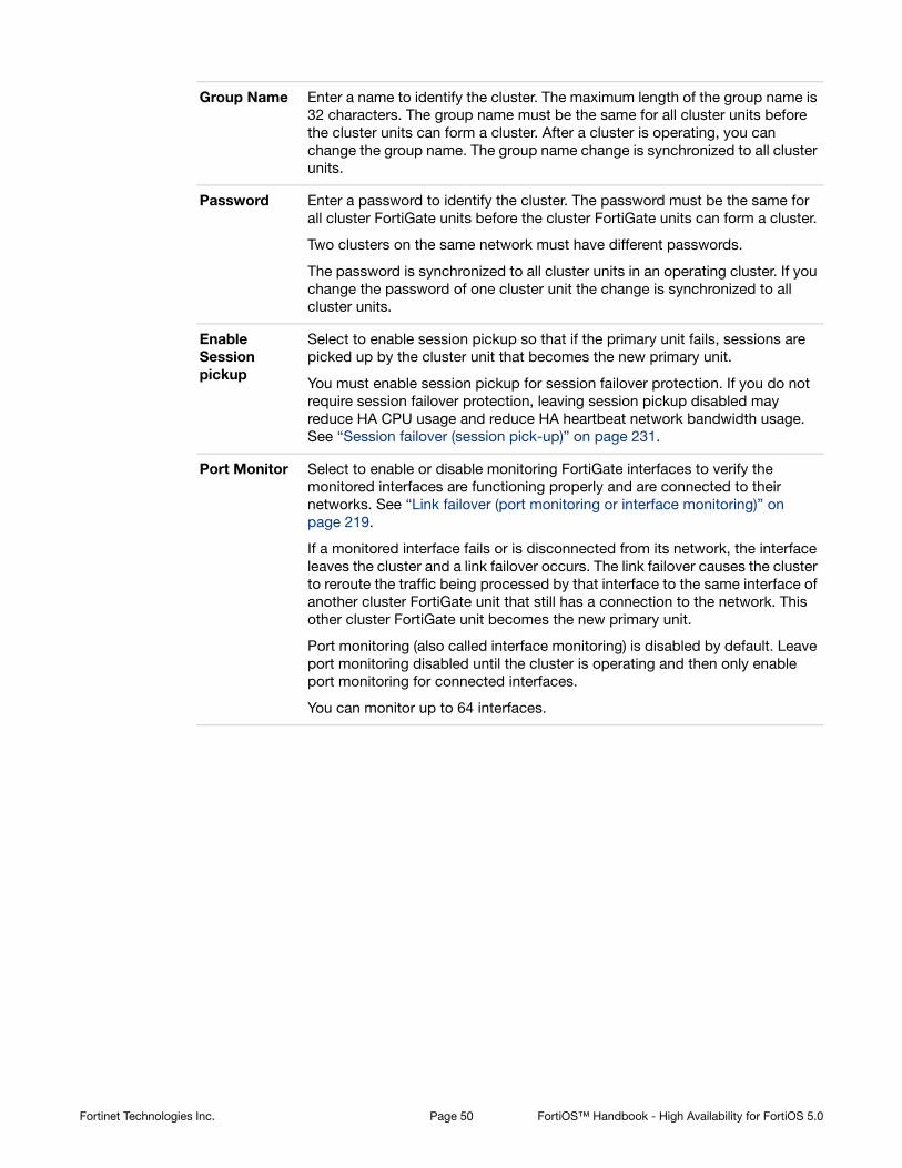
Group Name Enter a name to identify the cluster. The maximum length of the group name is 32 characters. The group name must be the same for all cluster units before the cluster units can form a cluster. After a cluster is operating, you can change the group name. The group name change is synchronized to all cluster units.
Password Enter a password to identify the cluster. The password must be the same for all cluster FortiGate units before the cluster FortiGate units can form a cluster.
Two clusters on the same network must have different passwords.
The password is synchronized to all cluster units in an operating cluster. If you change the password of one cluster unit the change is synchronized to all cluster units.
Enable Session pickup
Select to enable session pickup so that if the primary unit fails, sessions are picked up by the cluster unit that becomes the new primary unit.
You must enable session pickup for session failover protection. If you do not require session failover protection, leaving session pickup disabled may reduce HA CPU usage and reduce HA heartbeat network bandwidth usage. See “Session failover (session pick-up)” on page 231.
Port Monitor Select to enable or disable monitoring FortiGate interfaces to verify the monitored interfaces are functioning properly and are connected to their networks. See “Link failover (port monitoring or interface monitoring)” on page 219.
If a monitored interface fails or is disconnected from its network, the interface leaves the cluster and a link failover occurs. The link failover causes the cluster to reroute the traffic being processed by that interface to the same interface of another cluster FortiGate unit that still has a connection to the network. This other cluster FortiGate unit becomes the new primary unit.
Port monitoring (also called interface monitoring) is disabled by default. Leave port monitoring disabled until the cluster is operating and then only enable port monitoring for connected interfaces.
You can monitor up to 64 interfaces.
Fortinet Technologies Inc. Page 50 FortiOS™ Handbook - High Availability for FortiOS 5.0

Heartbeat Interface
Select to enable or disable HA heartbeat communication for each interface in the cluster and set the heartbeat interface priority. The heartbeat interface with the highest priority processes all heartbeat traffic. If two or more heartbeat interfaces have the same priority, the heartbeat interface with the lowest hash map order value processes all heartbeat traffic. The web-based manager lists interfaces in alphanumeric order:
• port1
• port2 through 9
• port10
Hash map order sorts interfaces in the following order:
• port1
• port10
• port2 through port9
The default heartbeat interface configuration is different for each FortiGate model. This default configuration usually sets the priority of two heartbeat interfaces to 50. You can accept the default heartbeat interface configuration or change it as required.
The heartbeat interface priority range is 0 to 512. The default priority when you select a new heartbeat interface is 0.
You must select at least one heartbeat interface. If heartbeat communication is interrupted, the cluster stops processing traffic. See “HA heartbeat and communication between cluster units” on page 193.
You can select up to 8 heartbeat interfaces. This limit only applies to units with more than 8 physical interfaces.
VDOM partitioning
If you are configuring virtual clustering, you can set the virtual domains to be in virtual cluster 1 and the virtual domains to be in virtual cluster 2. The root virtual domain must always be in virtual cluster 1. See “Virtual clusters” on page 117.
Fortinet Technologies Inc. Page 51 FortiOS™ Handbook - High Availability for FortiOS 5.0

Configuring and connecting HA clusters
This chapter contains general procedures and descriptions as well as detailed configuration examples that describe how to configure FortiGate HA clusters.
The examples in this chapter include example values only. In most cases you will substitute your own values. The examples in this chapter also do not contain detailed descriptions of configuration parameters.
This chapter contains the following sections:
• About the procedures in this chapter
• Example: NAT/Route mode active-passive HA configuration
• Example: Transparent mode active-active HA configuration
• Example: advanced Transparent mode active-active HA configuration
• Example: converting a standalone FortiGate unit to a cluster
• Example: adding a new unit to an operating cluster
• Example: replacing a failed cluster unit
• Example: HA and 802.3ad aggregated interfaces
• Example: HA and redundant interfaces
• Troubleshooting HA clusters
About the procedures in this chapter
The procedures in this chapter describe some of many possible sequences of steps for configuring HA clustering. As you become more experienced with FortiOS HA you may choose to use a different sequence of configuration steps.
For simplicity, many of these procedures assume that you are starting with new FortiGate units set to the factory default configuration. However, starting from the default configuration is not a requirement for a successful HA deployment. FortiGate HA is flexible enough to support a successful configuration from many different starting points.
Example: NAT/Route mode active-passive HA configuration
This section describes a simple HA network topology that includes an HA cluster of two FortiGate-620B units in NAT/Route mode installed between an internal network and the Internet.
• Example NAT/Route mode HA network topology
• General configuration steps
• Configuring a NAT/Route mode active-passive cluster of two FortiGate-620B units - web-based manager
• Configuring a NAT/Route mode active-passive cluster of two FortiGate-620B units - CLI
Page 52

Example NAT/Route mode HA network topology
Figure 5 shows a typical FortiGate-620B HA cluster consisting of two FortiGate-620B units (620_ha_1 and 620_ha_2) connected to the same internal (port2) and external (port1) networks.
Figure 5: Example NAT/Route mode HA network topology
Port3 and port4 are the default FortiGate-620B heartbeat interfaces. Because the cluster consists of two FortiGate units, you can make the connections between the heartbeat interfaces using crossover cables. You could also use switches and regular ethernet cables.
General configuration steps
The section includes web-based manager and CLI procedures. These procedures assume that the FortiGate-620B units are running the same FortiOS firmware build and are set to the factory default configuration.
General configuration steps
1. Configure the FortiGate units for HA operation.
• Optionally change each unit’s host name.
• Configure HA.
2. Connect the cluster to the network.
3. Confirm that the cluster units are operating as a cluster and add basic configuration settings to the cluster.
• View cluster status from the web-based manager or CLI.
• Add a password for the admin administrative account.
• Change the IP addresses and netmasks of the internal and external interfaces.
• Add a default route.
InternalNetwork
10.11.101.0
Router
172.20.120.2Switch
Switch
620_ha_1
620_ha_2
Port1
172.20.120.141
Port1
172.20.120.141
Port2
10.11.101.100
Port2
10.11.101.100Port3
Port3
Port4
Port4
Sw
S
Fortinet Technologies Inc. Page 53 FortiOS™ Handbook - High Availability for FortiOS 5.0

Configuring a NAT/Route mode active-passive cluster of two FortiGate-620B units - web-based manager
Use the following procedures to configure two FortiGate-620B units for NAT/Route HA operation using the FortiGate web-based manager. These procedures assume you are starting with two FortiGate-620B units with factory default settings.
To configure the first FortiGate-620B unit (host name 620_ha_1)
1. Power on the first FortiGate unit.
2. On your management computer with an Ethernet connection, set the static IP address to 192.168.1.2 and the netmask to 255.255.255.0.
3. On a management computer, start a web browser and browse to the address https://192.168.1.99 (remember to include the “s” in https://).
The FortiGate login is displayed.
4. Type admin in the Name field and select Login.
The FortiGate dashboard is displayed.
5. On the System Information dashboard widget beside Host Name, select Change.
6. Enter a new Host Name for this FortiGate unit.
7. Select OK.
8. Go to System > Config > HA and change the following settings:
9. Select OK.
The FortiGate unit negotiates to establish an HA cluster. When you select OK you may temporarily lose connectivity with the FortiGate unit as the HA cluster negotiates and the FGCP changes the MAC address of the FortiGate unit interfaces (see “Cluster virtual MAC
Give each cluster unit a unique host name to make the individual units easier to identify when they are part of a functioning cluster. The default FortiGate unit host name is the FortiGate serial number. You may want to change this host name to something more meaningful for your network.
Make sure your FortiGate interfaces are configured with static IP addresses. If any interface gets its address using DHCP you will not be able to configure HA.
New Name 620_ha_1
Mode Active-Passive
Group Name example1.com
Password HA_pass_1
This is the minimum recommended configuration for an active-active HA cluster. You can also configure other HA options, but if you wait until after the cluster is operating you will only have to configure these options once for the cluster instead of separately for each unit in the cluster.
Fortinet Technologies Inc. Page 54 FortiOS™ Handbook - High Availability for FortiOS 5.0

addresses” on page 200). The MAC addresses of the FortiGate-620B interfaces change to the following virtual MAC addresses:
• port1 interface virtual MAC: 00-09-0f-09-00-00
• port10 interface virtual MAC: 00-09-0f-09-00-01
• port11 interface virtual MAC: 00-09-0f-09-00-02
• port12 interface virtual MAC: 00-09-0f-09-00-03
• port13 interface virtual MAC: 00-09-0f-09-00-04
• port14 interface virtual MAC: 00-09-0f-09-00-05
• port15 interface virtual MAC: 00-09-0f-09-00-06
• port16 interface virtual MAC: 00-09-0f-09-00-07
• port17 interface virtual MAC: 00-09-0f-09-00-08
• port18 interface virtual MAC: 00-09-0f-09-00-09
• port19 interface virtual MAC: 00-09-0f-09-00-0a
• port2 interface virtual MAC: 00-09-0f-09-00-0b
• port20 interface virtual MAC: 00-09-0f-09-00-0c
• port3 interface virtual MAC: 00-09-0f-09-00-0d
• port4 interface virtual MAC: 00-09-0f-09-00-0e
• port5 interface virtual MAC: 00-09-0f-09-00-0f
• port6 interface virtual MAC: 00-09-0f-09-00-10
• port7 interface virtual MAC: 00-09-0f-09-00-11
• port8 interface virtual MAC: 00-09-0f-09-00-12
• port9 interface virtual MAC: 00-09-0f-09-00-13
To reconnect sooner, you can update the ARP table of your management PC by deleting the ARP table entry for the FortiGate unit (or just deleting all arp table entries). You may be able to delete the arp table of your management PC from a command prompt using a command similar to arp -d.
To confirm these MAC address changes, you can use the get hardware nic (or diagnose hardware deviceinfo nic) CLI command to view the virtual MAC address of any FortiGate unit interface. For example, use the following command to view the port1 interface virtual MAC address (MAC) and the port1 permanent MAC address (Permanent_HWaddr):get hardware nic port1
.
.
.
MAC: 00:09:0f:09:00:00
Permanent_HWaddr: 02:09:0f:78:18:c9
.
.
.
10.Power off the first FortiGate unit (620_ha_1).
To configure the second FortiGate-620B unit (host name 620_ha_2)
1. Power on the second FortiGate unit.
2. On a management computer, start a web browser and browse to the address https://192.168.1.99 (remember to include the “s” in https://).
The FortiGate login is displayed.
Fortinet Technologies Inc. Page 55 FortiOS™ Handbook - High Availability for FortiOS 5.0

3. Type admin in the Name field and select Login.
The FortiGate dashboard is displayed.
4. On the System Information dashboard widget, beside Host Name select Change.
5. Enter a new Host Name for this FortiGate unit.
6. Select OK.
7. Go to System > Config > HA and change the following settings:
8. Select OK.
The FortiGate unit negotiates to establish an HA cluster. When you select OK you may temporarily lose connectivity with the FortiGate unit as the HA cluster negotiates and because the FGCP changes the MAC address of the FortiGate unit interfaces.
To reconnect sooner, you can update the ARP table of your management PC by deleting the ARP table entry for the FortiGate unit (or just deleting all arp table entries). You may be able to delete the arp table of your management PC from a command prompt using a command similar to arp -d.
9. Power off the second FortiGate unit.
To connect the cluster to the network
1. Connect the port1 interfaces of 620_ha_1 and 620_ha_2 to a switch connected to the Internet.
2. Connect the port2 interfaces of 620_ha_1 and 620_ha_2 to a switch connected to the internal network.
3. Connect the port3 interfaces of 620_ha_1 and 620_ha_2 together. You can use a crossover Ethernet cable or regular Ethernet cables and a switch.
4. Connect the port4 interfaces of the cluster units together. You can use a crossover Ethernet cable or regular Ethernet cables and a switch.
5. Power on the cluster units.
The units start and negotiate to choose the primary unit and the subordinate unit. This negotiation occurs with no user intervention and normally takes less than a minute.
When negotiation is complete the cluster is ready to be configured for your network.
To view cluster status
Use the following steps to view the cluster dashboard and cluster members list to confirm that the cluster units are operating as a cluster.
New Name 620_ha_2
Mode Active-Passive
Group Name example1.com
Password HA_pass_1
Once the cluster is operating, because configuration changes are synchronized to all cluster units, configuring the cluster is the same as configuring an individual FortiGate unit. You could have performed the following configuration steps separately on each FortiGate unit before you connected them to form a cluster.
Fortinet Technologies Inc. Page 56 FortiOS™ Handbook - High Availability for FortiOS 5.0

1. Start Internet Explorer and browse to the address https://192.168.1.99 (remember to include the “s” in https://).
The FortiGate Login is displayed.
2. Type admin in the Name field and select Login.
The FortiGate dashboard is displayed.
The System Information dashboard widget shows the Cluster Name (example1.com) and the host names and serial numbers of the Cluster Members. The Unit Operation widget shows multiple cluster units.
Figure 6: Sample FortiGate-620B System Information dashboard widget
3. Go to System > Config > HA to view the cluster members list.
The list shows both cluster units, their host names, their roles in the cluster, and their priorities. You can use this list to confirm that the cluster is operating normally. For example, if the list shows only one cluster unit then the other unit has left the cluster for some reason.
Figure 7: Sample FortiGate-620B cluster members list
To troubleshoot the cluster configuration
If the cluster members list and the dashboard do not display information for both cluster units, the FortiGate units are not functioning as a cluster. See “Troubleshooting HA clusters” on page 112 to troubleshoot the cluster.
To add basic configuration settings to the cluster
Use the following steps to configure the cluster to connect to its network. The following are example configuration steps only and do not represent all of the steps required to configure the cluster for a given network.
1. Log into the cluster web-based manager.
2. Go to System > Admin > Administrators.
3. For admin, select the Change Password icon
4. Enter and confirm a new password.
Fortinet Technologies Inc. Page 57 FortiOS™ Handbook - High Availability for FortiOS 5.0

5. Select OK.
6. Go to System > Network > Interfaces.
7. Edit the port2 interface and change IP/Netmask to 10.11.101.100/24.
8. Select OK.
9. Edit the port1 interface and change IP/Netmask to 172.20.120.141/24.
10.Select OK.
11.Go to Router > Static > Static Routes.
12.Change the default route.
13.Select OK.
Configuring a NAT/Route mode active-passive cluster of two FortiGate-620B units - CLI
Use the following procedures to configure two FortiGate-620B units for NAT/Route HA operation using the FortiGate CLI. These procedures assume you are starting with two FortiGate-620B units with factory default settings.
To configure the first FortiGate-620B unit (host name 620_ha_1)
1. Power on the FortiGate unit.
2. Connect a null modem cable to the communications port of the management computer and to the FortiGate Console port.
3. Start HyperTerminal (or any terminal emulation program), enter a name for the connection, and select OK.
4. Configure HyperTerminal to connect directly to the communications port on the computer to which you have connected the null modem cable and select OK.
5. Select the following port settings and select OK.
After changing the IP address of the port1 interface you may have to change the IP address of your management computer and then reconnect to the port1 interface using the 172.20.120.141 IP address.
Destination IP/Mask 0.0.0.0/0.0.0.0
Gateway 172.20.120.2
Device port1
Distance 10
Make sure your FortiGate interfaces are configured with static IP addresses. If any interface gets its address using DHCP you will not be able to configure HA.
Bits per second 9600
Data bits 8
Fortinet Technologies Inc. Page 58 FortiOS™ Handbook - High Availability for FortiOS 5.0

6. Press Enter to connect to the FortiGate CLI.
The FortiGate unit CLI login prompt appears.
If the prompt does not appear, press Enter. If it still does not appear, power off your FortiGate unit and power it back on. If you are connected, at this stage you will see startup messages that will confirm you are connected. The login prompt will appear after the startup has completed.
7. Type admin and press Enter twice.
8. Change the host name for this FortiGate unit.config system global
set hostname 620_ha_1
end
9. Configure HA settings.config system ha
set mode a-p
set group-name example1.com
set password HA_pass_1
end
The FortiGate unit negotiates to establish an HA cluster. You may temporarily lose network connectivity with the FortiGate unit as the HA cluster negotiates and the FGCP changes the MAC address of the FortiGate unit interfaces (see “Cluster virtual MAC addresses” on page 200). The MAC addresses of the FortiGate-620B interfaces change to the following virtual MAC addresses:
• port1 interface virtual MAC: 00-09-0f-09-00-00
• port10 interface virtual MAC: 00-09-0f-09-00-01
• port11 interface virtual MAC: 00-09-0f-09-00-02
• port12 interface virtual MAC: 00-09-0f-09-00-03
• port13 interface virtual MAC: 00-09-0f-09-00-04
• port14 interface virtual MAC: 00-09-0f-09-00-05
• port15 interface virtual MAC: 00-09-0f-09-00-06
• port16 interface virtual MAC: 00-09-0f-09-00-07
• port17 interface virtual MAC: 00-09-0f-09-00-08
• port18 interface virtual MAC: 00-09-0f-09-00-09
• port19 interface virtual MAC: 00-09-0f-09-00-0a
• port2 interface virtual MAC: 00-09-0f-09-00-0b
• port20 interface virtual MAC: 00-09-0f-09-00-0c
• port3 interface virtual MAC: 00-09-0f-09-00-0d
• port4 interface virtual MAC: 00-09-0f-09-00-0e
• port5 interface virtual MAC: 00-09-0f-09-00-0f
• port6 interface virtual MAC: 00-09-0f-09-00-10
• port7 interface virtual MAC: 00-09-0f-09-00-11
• port8 interface virtual MAC: 00-09-0f-09-00-12
Parity None
Stop bits 1
Flow control None
Fortinet Technologies Inc. Page 59 FortiOS™ Handbook - High Availability for FortiOS 5.0
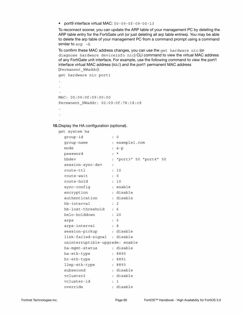
• port9 interface virtual MAC: 00-09-0f-09-00-13
To reconnect sooner, you can update the ARP table of your management PC by deleting the ARP table entry for the FortiGate unit (or just deleting all arp table entries). You may be able to delete the arp table of your management PC from a command prompt using a command similar to arp -d.
To confirm these MAC address changes, you can use the get hardware nic (or diagnose hardware deviceinfo nic) CLI command to view the virtual MAC address of any FortiGate unit interface. For example, use the following command to view the port1 interface virtual MAC address (MAC) and the port1 permanent MAC address (Permanent_HWaddr):get hardware nic port1
.
.
.
MAC: 00:09:0f:09:00:00
Permanent_HWaddr: 02:09:0f:78:18:c9
.
.
.
10.Display the HA configuration (optional).get system ha
group-id : 0
group-name : example1.com
mode : a-p
password : *
hbdev : "port3" 50 "port4" 50
session-sync-dev :
route-ttl : 10
route-wait : 0
route-hold : 10
sync-config : enable
encryption : disable
authentication : disable
hb-interval : 2
hb-lost-threshold : 6
helo-holddown : 20
arps : 5
arps-interval : 8
session-pickup : disable
link-failed-signal : disable
uninterruptible-upgrade: enable
ha-mgmt-status : disable
ha-eth-type : 8890
hc-eth-type : 8891
l2ep-eth-type : 8893
subsecond : disable
vcluster2 : disable
vcluster-id : 1
override : disable
Fortinet Technologies Inc. Page 60 FortiOS™ Handbook - High Availability for FortiOS 5.0

priority : 128
monitor :
pingserver-monitor-interface:
pingserver-failover-threshold: 0
pingserver-flip-timeout: 60
vdom : "root"
11.Power off the FortiGate unit.
To configure the second FortiGate-620B unit (host name 620_ha_2)
1. Power on the FortiGate unit.
2. Connect a null modem cable to the communications port of the management computer and to the FortiGate Console port.
3. Start HyperTerminal, enter a name for the connection, and select OK.
4. Configure HyperTerminal to connect directly to the communications port on the computer to which you have connected the null modem cable and select OK.
5. Select the following port settings and select OK.
6. Press Enter to connect to the FortiGate CLI.
The FortiGate unit CLI login prompt appears.
7. Type admin and press Enter twice.
8. Change the host name for this FortiGate unit.config system global
set hostname 620_ha_2
end
9. Configure HA settings.config system ha
set mode a-p
set group-name example1.com
set password HA_pass_1
end
The FortiGate unit negotiates to establish an HA cluster. You may temporarily lose network connectivity with the FortiGate unit as the HA cluster negotiates and because the FGCP changes the MAC address of the FortiGate unit interfaces.
To reconnect sooner, you can update the ARP table of your management PC by deleting the ARP table entry for the FortiGate unit (or just deleting all arp table entries). You may be able to delete the arp table of your management PC from a command prompt using a command similar to arp -d.
Bits per second 9600
Data bits 8
Parity None
Stop bits 1
Flow control None
Fortinet Technologies Inc. Page 61 FortiOS™ Handbook - High Availability for FortiOS 5.0

10.Display the HA configuration (optional).get system ha
group-id : 0
group-name : example1.com
mode : a-p
password : *
hbdev : "port3" 50 "port4" 50
session-sync-dev :
route-ttl : 10
route-wait : 0
route-hold : 10
sync-config : enable
encryption : disable
authentication : disable
hb-interval : 2
hb-lost-threshold : 6
helo-holddown : 20
arps : 5
arps-interval : 8
session-pickup : disable
link-failed-signal : disable
uninterruptible-upgrade: enable
ha-mgmt-status : disable
ha-eth-type : 8890
hc-eth-type : 8891
l2ep-eth-type : 8893
subsecond : disable
vcluster2 : disable
vcluster-id : 1
override : disable
priority : 128
monitor :
pingserver-monitor-interface:
pingserver-failover-threshold: 0
pingserver-flip-timeout: 60
vdom : "root"
11.Power off the FortiGate unit.
To connect the cluster to the network
1. Connect the port1 interfaces of 620_ha_1 and 620_ha_2 to a switch connected to the Internet.
2. Connect the port2 interfaces of 620_ha_1 and 620_ha_2 to a switch connected to the internal network.
3. Connect the port3 interfaces of 620_ha_1 and 620_ha_2 together. You can use a crossover Ethernet cable or regular Ethernet cables and a switch.
4. Connect the port4 interfaces of the cluster units together. You can use a crossover Ethernet cable or regular Ethernet cables and a switch.
Fortinet Technologies Inc. Page 62 FortiOS™ Handbook - High Availability for FortiOS 5.0

5. Power on the cluster units.
The units start and negotiate to choose the primary unit and the subordinate unit. This negotiation occurs with no user intervention and normally takes less than a minute.
When negotiation is complete the cluster is ready to be configured for your network.
To view cluster status
Use the following steps to view cluster status from the CLI.
1. Determine which cluster unit is the primary unit.
• Use the null-modem cable and serial connection to re-connect to the CLI of one of the cluster units.
• Enter the command get system status.
• If the command output includes Current HA mode: a-a, master, the cluster units are operating as a cluster and you have connected to the primary unit. Continue with Step 2.
• If the command output includes Current HA mode: a-a, backup, you have connected to a subordinate unit. Connect the null-modem cable to the other cluster unit, which should be the primary unit and continue with Step 2.
2. Enter the following command to confirm the HA configuration of the cluster:get system ha status
Model: 620
Mode: a-a
Group: 0
Debug: 0
ses_pickup: disable
Master:128 620_ha_2 FG600B3908600825 0
Slave :128 620_ha_1 FG600B3908600705 1
number of vcluster: 1
vcluster 1: work 169.254.0.1
Master:0 FG600B3908600825
Slave :1 FG600B3908600705
The command output shows both cluster units, their host names, their roles in the cluster, and their priorities. You can use this command to confirm that the cluster is operating normally. For example, if the command shows only one cluster unit then the other unit has left the cluster for some reason.
To troubleshoot the cluster configuration
If the cluster members list and the dashboard do not display information for both cluster units the FortiGate units are not functioning as a cluster. See “Troubleshooting HA clusters” on page 112 to troubleshoot the cluster.
To add basic configuration settings to the cluster
Use the following steps to add some basic settings to the cluster so that it can connect to the network.
If the command output includes Current HA mode: standalone, the cluster unit is not operating in HA mode and you should review your HA configuration.
Fortinet Technologies Inc. Page 63 FortiOS™ Handbook - High Availability for FortiOS 5.0

1. Log into the primary unit CLI.
2. Add a password for the admin administrative account.config system admin
edit admin
set password <password_str>
end
3. Configure the port1 and port2 interfaces.config system interface
edit port1
set ip 172.20.120.141/24
next
edit port2
set ip 10.11.101.100/24
end
4. Add a default route.config router static
edit 1
set dst 0.0.0.0 0.0.0.0
set gateway 172.20.120.2
set device port1
end
Example: Transparent mode active-active HA configuration
This section describes a simple HA network topology that includes an HA cluster of two FortiGate-620B units installed between an internal network and the Internet and running in Transparent mode.
• Example Transparent mode HA network topology
• General configuration steps
Example Transparent mode HA network topology
Figure 8 shows a Transparent mode FortiGate-620B HA cluster consisting of two FortiGate-620B units (620_ha_1 and 620_ha_2) installed between the Internet and internal network. The topology includes a router that performs NAT between the internal network and the Internet. The cluster management IP address is 10.11.101.100.
Fortinet Technologies Inc. Page 64 FortiOS™ Handbook - High Availability for FortiOS 5.0

Figure 8: Transparent mode HA network topology
Port3 and port4 are the default FortiGate-620B heartbeat interfaces. Because the cluster consists of two FortiGate units, you can make the connections between the heartbeat interfaces using crossover cables. You could also use switches and regular ethernet cables.
General configuration steps
This section includes web-based manager and CLI procedures. These procedures assume that the FortiGate-620B units are running the same FortiOS firmware build and are set to the factory default configuration.
In this example, the configuration steps are identical to the NAT/Route mode configuration steps until the cluster is operating. When the cluster is operating, you can switch to Transparent mode and add basic configuration settings to cluster.
General configuration steps
1. Configure the FortiGate units for HA operation.
• Optionally change each unit’s host name.
• Configure HA.
2. Connect the cluster to the network.
3. Confirm that the cluster units are operating as a cluster.
4. Switch the cluster to Transparent mode and add basic configuration settings to the cluster.
• Switch to Transparent mode, add the management IP address and a default route.
• Add a password for the admin administrative account.
• View cluster status from the web-based manager or CLI.
InternalNetwork
10.11.101.0
ClusterManagement IP10.11.101.100
M
10.11.101.2
Router
172.20.120.2
Switch
Switch
620_ha_1
620_ha_2
Port1
Port1
Port2
Port2Port3
Port3
Port4
Port4
1
Sw
S
Fortinet Technologies Inc. Page 65 FortiOS™ Handbook - High Availability for FortiOS 5.0

Configuring a Transparent mode active-active cluster of two FortiGate-620B units - web-based manager
Use the following procedures to configure the FortiGate-620B units for HA operation using the FortiGate web-based manager. These procedures assume you are starting with two FortiGate-620B units with factory default settings.
To configure the first FortiGate-620B unit (host name 620_ha_1)
1. Power on the first FortiGate unit.
2. Set the IP address of a management computer with an Ethernet connection to the static IP address 192.168.1.2 and a netmask of 255.255.255.0.
3. On a management computer, start a web browser and browse to the address https://192.168.1.99 (remember to include the “s” in https://).
The FortiGate login is displayed.
4. Type admin in the Name field and select Login.
The FortiGate dashboard is displayed.
5. On the System Information dashboard widget, beside Host Name select Change.
6. Enter a new Host Name for this FortiGate unit.
7. Select OK.
8. Go to System > Config > HA and change the following settings:
9. Select OK.
The FortiGate unit negotiates to establish an HA cluster. When you select OK you may temporarily lose connectivity with the FortiGate unit as the HA cluster negotiates and the FGCP changes the MAC address of the FortiGate unit interfaces (see “Cluster virtual MAC addresses” on page 200). The MAC addresses of the FortiGate-620B interfaces change to the following virtual MAC addresses:
• port1 interface virtual MAC: 00-09-0f-09-00-00
• port10 interface virtual MAC: 00-09-0f-09-00-01
• port11 interface virtual MAC: 00-09-0f-09-00-02
Waiting until you have established the cluster to switch to Transparent mode means fewer configuration steps because you can switch the mode of the cluster in one step.
New Name 620_ha_1
Mode Active-Active
Group Name example2.com
Password HA_pass_2
This is the minimum recommended configuration for an active-active HA cluster. You can configure other HA options at this point, but if you wait until the cluster is operating you will only have to configure these options once for the cluster instead of separately for each cluster unit.
Fortinet Technologies Inc. Page 66 FortiOS™ Handbook - High Availability for FortiOS 5.0
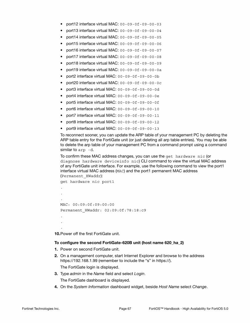
• port12 interface virtual MAC: 00-09-0f-09-00-03
• port13 interface virtual MAC: 00-09-0f-09-00-04
• port14 interface virtual MAC: 00-09-0f-09-00-05
• port15 interface virtual MAC: 00-09-0f-09-00-06
• port16 interface virtual MAC: 00-09-0f-09-00-07
• port17 interface virtual MAC: 00-09-0f-09-00-08
• port18 interface virtual MAC: 00-09-0f-09-00-09
• port19 interface virtual MAC: 00-09-0f-09-00-0a
• port2 interface virtual MAC: 00-09-0f-09-00-0b
• port20 interface virtual MAC: 00-09-0f-09-00-0c
• port3 interface virtual MAC: 00-09-0f-09-00-0d
• port4 interface virtual MAC: 00-09-0f-09-00-0e
• port5 interface virtual MAC: 00-09-0f-09-00-0f
• port6 interface virtual MAC: 00-09-0f-09-00-10
• port7 interface virtual MAC: 00-09-0f-09-00-11
• port8 interface virtual MAC: 00-09-0f-09-00-12
• port9 interface virtual MAC: 00-09-0f-09-00-13
To reconnect sooner, you can update the ARP table of your management PC by deleting the ARP table entry for the FortiGate unit (or just deleting all arp table entries). You may be able to delete the arp table of your management PC from a command prompt using a command similar to arp -d.
To confirm these MAC address changes, you can use the get hardware nic (or diagnose hardware deviceinfo nic) CLI command to view the virtual MAC address of any FortiGate unit interface. For example, use the following command to view the port1 interface virtual MAC address (MAC) and the port1 permanent MAC address (Permanent_HWaddr):get hardware nic port1
.
.
.
MAC: 00:09:0f:09:00:00
Permanent_HWaddr: 02:09:0f:78:18:c9
.
.
.
10.Power off the first FortiGate unit.
To configure the second FortiGate-620B unit (host name 620_ha_2)
1. Power on second FortiGate unit.
2. On a management computer, start Internet Explorer and browse to the address https://192.168.1.99 (remember to include the “s” in https://).
The FortiGate login is displayed.
3. Type admin in the Name field and select Login.
The FortiGate dashboard is displayed.
4. On the System Information dashboard widget, beside Host Name select Change.
Fortinet Technologies Inc. Page 67 FortiOS™ Handbook - High Availability for FortiOS 5.0

5. Enter a new Host Name for this FortiGate unit.
6. Select OK.
7. Go to System > Config > HA and change the following settings:
8. Select OK.
The FortiGate unit negotiates to establish an HA cluster. When you select OK you may temporarily lose connectivity with the FortiGate unit as the HA cluster negotiates and because the FGCP changes the MAC address of the FortiGate unit interfaces.
To reconnect sooner, you can update the ARP table of your management PC by deleting the ARP table entry for the FortiGate unit (or just deleting all arp table entries). You may be able to delete the arp table of your management PC from a command prompt using a command similar to arp -d.
9. Power off the second FortiGate unit.
To connect the cluster to the network
1. Connect the port1 interfaces of 620_ha_1 and 620_ha_2 to a switch connected to the Internet.
2. Connect the port2 interfaces of 620_ha_1 and 620_ha_2 to a switch connected to the internal network.
3. Connect the port3 interfaces of 620_ha_1 and 620_ha_2 together. You can use a crossover Ethernet cable or regular Ethernet cables and a switch.
4. Connect the port4 interfaces of the cluster units together. You can use a crossover Ethernet cable or regular Ethernet cables and a switch.
5. Power on the cluster units.
The units start and negotiate to choose the primary unit and the subordinate unit. This negotiation occurs with no user intervention and normally takes less than a minute.
When negotiation is complete the cluster is ready to be configured for your network.
To switch the cluster to Transparent mode
Switching from NAT/Route to Transparent mode involves adding the Transparent mode management IP address and default route.
1. Start a web browser and browse to the address https://192.168.1.99 (remember to include the “s” in https://).
The FortiGate Login is displayed.
2. Type admin in the Name field and select Login.
New Name 620_ha_2
Mode Active-Active
Group Name example2.com
Password HA_pass_2
Since configuration changes are synchronized to all cluster units, switching the cluster to operate in Transparent mode once the cluster is operating is the same as switching an individual FortiGate unit to Transparent mode. You could have performed the following configuration steps separately on each FortiGate unit before you connected them to form a cluster.
Fortinet Technologies Inc. Page 68 FortiOS™ Handbook - High Availability for FortiOS 5.0

3. Under System Information, beside Operation Mode select Change.
4. Set Operation Mode to Transparent.
5. Configure basic Transparent mode settings.
6. Select Apply.
The cluster switches to operating in Transparent mode. The virtual MAC addresses assigned to the cluster interfaces do not change.
To view cluster status
Use the following steps to view the cluster dashboard and cluster members list to confirm that the cluster units are operating as a cluster.
1. Start Internet Explorer and browse to the address https://10.11.101.100 (remember to include the “s” in https://).
The FortiGate Login is displayed.
2. Type admin in the Name field and select Login.
The FortiGate dashboard is displayed.
The System Information dashboard widget shows the Cluster Name (example2.com) and the host names and serial numbers of the Cluster Members. The Unit Operation widget shows multiple cluster units.
3. Go to System > Config > HA to view the cluster members list.
The list shows both cluster units, their host names, their roles in the cluster, and their priorities. You can use this list to confirm that the cluster is operating normally. For example, if the list shows only one cluster unit then the other unit has left the cluster for some reason.
To troubleshoot the cluster configuration
If the cluster members list and the dashboard do not display information for both cluster units, the FortiGate units are not functioning as a cluster. See “Troubleshooting HA clusters” on page 112 to troubleshoot the cluster.
To add basic configuration settings to the cluster
Use the following steps to configure the cluster. Note that the following are example configuration steps only and do not represent all of the steps required to configure the cluster for a given network.
1. Log into the cluster web-based manager.
2. Go to System > Admin > Administrators.
3. For admin, select the Change Password icon
4. Enter and confirm a new password.
Operation Mode Transparent
Management IP/Mask 10.11.101.100/24
Default Gateway 10.11.101.2
Once the cluster is operating, because configuration changes are synchronized to all cluster units, configuring the cluster is the same as configuring an individual FortiGate unit. You could have performed the following configuration steps separately on each FortiGate unit before you connected them to form a cluster.
Fortinet Technologies Inc. Page 69 FortiOS™ Handbook - High Availability for FortiOS 5.0
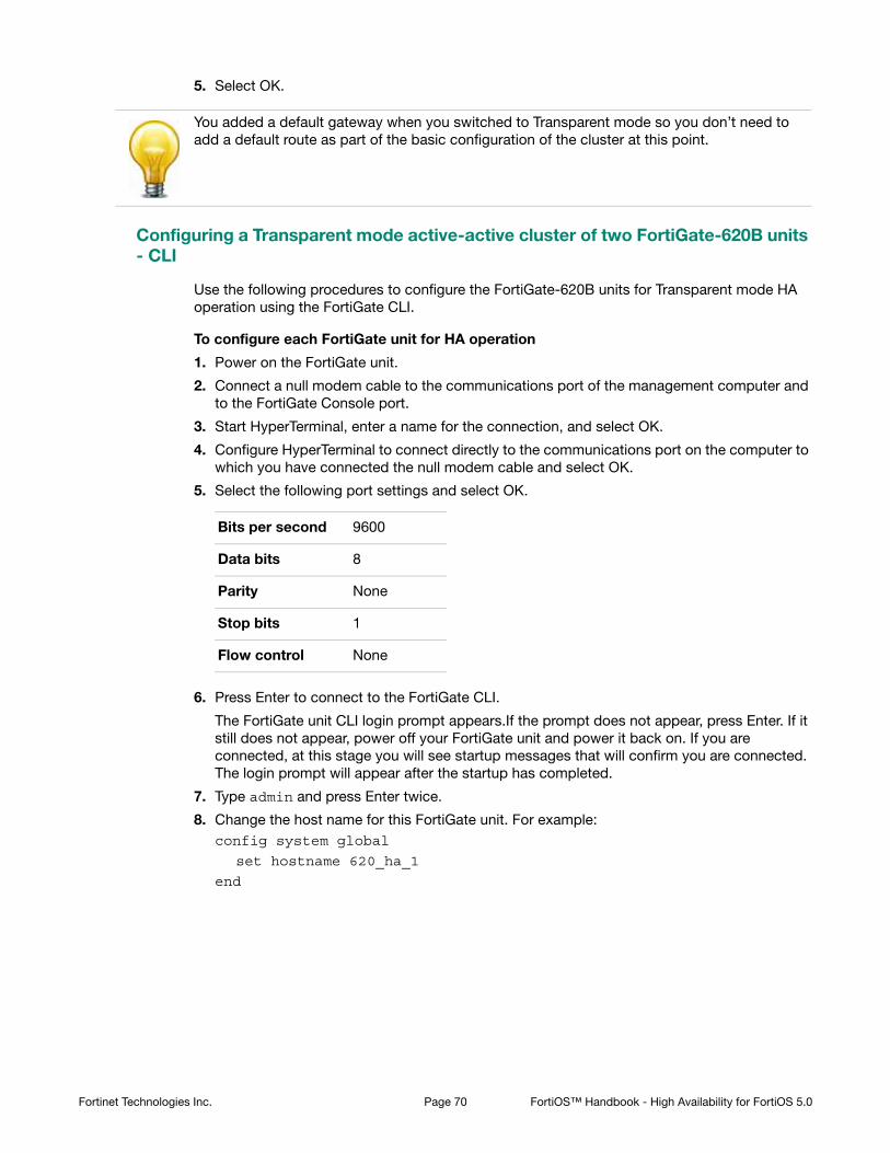
5. Select OK.
Configuring a Transparent mode active-active cluster of two FortiGate-620B units - CLI
Use the following procedures to configure the FortiGate-620B units for Transparent mode HA operation using the FortiGate CLI.
To configure each FortiGate unit for HA operation
1. Power on the FortiGate unit.
2. Connect a null modem cable to the communications port of the management computer and to the FortiGate Console port.
3. Start HyperTerminal, enter a name for the connection, and select OK.
4. Configure HyperTerminal to connect directly to the communications port on the computer to which you have connected the null modem cable and select OK.
5. Select the following port settings and select OK.
6. Press Enter to connect to the FortiGate CLI.
The FortiGate unit CLI login prompt appears.If the prompt does not appear, press Enter. If it still does not appear, power off your FortiGate unit and power it back on. If you are connected, at this stage you will see startup messages that will confirm you are connected. The login prompt will appear after the startup has completed.
7. Type admin and press Enter twice.
8. Change the host name for this FortiGate unit. For example:config system global
set hostname 620_ha_1
end
You added a default gateway when you switched to Transparent mode so you don’t need to add a default route as part of the basic configuration of the cluster at this point.
Bits per second 9600
Data bits 8
Parity None
Stop bits 1
Flow control None
Fortinet Technologies Inc. Page 70 FortiOS™ Handbook - High Availability for FortiOS 5.0

9. Configure HA settings.config system ha
set mode a-a
set group-name example2.com
set password HA_pass_2
end
The FortiGate unit negotiates to establish an HA cluster. You may temporarily lose network connectivity with the FortiGate unit as the HA cluster negotiates and the FGCP changes the MAC address of the FortiGate unit interfaces (see “Cluster virtual MAC addresses” on page 200). The MAC addresses of the FortiGate-620B interfaces change to the following virtual MAC addresses:
• port1 interface virtual MAC: 00-09-0f-09-00-00
• port10 interface virtual MAC: 00-09-0f-09-00-01
• port11 interface virtual MAC: 00-09-0f-09-00-02
• port12 interface virtual MAC: 00-09-0f-09-00-03
• port13 interface virtual MAC: 00-09-0f-09-00-04
• port14 interface virtual MAC: 00-09-0f-09-00-05
• port15 interface virtual MAC: 00-09-0f-09-00-06
• port16 interface virtual MAC: 00-09-0f-09-00-07
• port17 interface virtual MAC: 00-09-0f-09-00-08
• port18 interface virtual MAC: 00-09-0f-09-00-09
• port19 interface virtual MAC: 00-09-0f-09-00-0a
• port2 interface virtual MAC: 00-09-0f-09-00-0b
• port20 interface virtual MAC: 00-09-0f-09-00-0c
• port3 interface virtual MAC: 00-09-0f-09-00-0d
• port4 interface virtual MAC: 00-09-0f-09-00-0e
• port5 interface virtual MAC: 00-09-0f-09-00-0f
• port6 interface virtual MAC: 00-09-0f-09-00-10
• port7 interface virtual MAC: 00-09-0f-09-00-11
• port8 interface virtual MAC: 00-09-0f-09-00-12
• port9 interface virtual MAC: 00-09-0f-09-00-13
To reconnect sooner, you can update the ARP table of your management PC by deleting the ARP table entry for the FortiGate unit (or just deleting all arp table entries). You may be able to delete the arp table of your management PC from a command prompt using a command similar to arp -d.
To confirm these MAC address changes, you can use the get hardware nic (or diagnose hardware deviceinfo nic) CLI command to view the virtual MAC address of any FortiGate unit interface. For example, use the following command to view the port1
This is the minimum recommended configuration for an active-active HA cluster. You can also configure other HA options, but if you wait until after the cluster is operating you will only have to configure these options once for the cluster instead of separately for each cluster unit.
Fortinet Technologies Inc. Page 71 FortiOS™ Handbook - High Availability for FortiOS 5.0

interface virtual MAC address (MAC) and the port1 permanent MAC address (Permanent_HWaddr):get hardware nic port1
.
.
.
MAC: 00:09:0f:09:00:00
Permanent_HWaddr: 02:09:0f:78:18:c9
.
.
.
10.Display the HA configuration (optional).get system ha
group-id : 0
group-name : example2.com
mode : a-a
password : *
hbdev : "port3" 50 "port4" 50
session-sync-dev :
route-ttl : 10
route-wait : 0
route-hold : 10
sync-config : enable
encryption : disable
authentication : disable
hb-interval : 2
hb-lost-threshold : 6
helo-holddown : 20
arps : 5
arps-interval : 8
session-pickup : disable
link-failed-signal : disable
uninterruptible-upgrade: enable
ha-mgmt-status : disable
ha-eth-type : 8890
hc-eth-type : 8891
l2ep-eth-type : 8893
subsecond : disable
vcluster2 : disable
vcluster-id : 1
override : disable
priority : 128
monitor :
pingserver-monitor-interface:
pingserver-failover-threshold: 0
pingserver-flip-timeout: 60
vdom : "root"
11.Power off the FortiGate unit.
Fortinet Technologies Inc. Page 72 FortiOS™ Handbook - High Availability for FortiOS 5.0

To configure the second FortiGate-620B unit (host name 620_ha_2)
1. Power on the FortiGate unit.
2. Connect a null modem cable to the communications port of the management computer and to the FortiGate Console port.
3. Start HyperTerminal, enter a name for the connection, and select OK.
4. Configure HyperTerminal to connect directly to the communications port on the computer to which you have connected the null modem cable and select OK.
5. Select the following port settings and select OK.
6. Press Enter to connect to the FortiGate CLI.
The FortiGate unit CLI login prompt appears.If the prompt does not appear, press Enter. If it still does not appear, power off your FortiGate unit and power it back on. If you are connected, at this stage you will see startup messages that will confirm you are connected. The login prompt will appear after the startup has completed.
7. Type admin and press Enter twice.
8. Change the host name for this FortiGate unit.config system global
set hostname 620_ha_2
end
9. Configure HA settings.config system ha
set mode a-a
set group-name example2.com
set password HA_pass_2
end
The FortiGate unit negotiates to establish an HA cluster. You may temporarily lose network connectivity with the FortiGate unit as the HA cluster negotiates and because the FGCP changes the MAC address of the FortiGate unit interfaces.
To reconnect sooner, you can update the ARP table of your management PC by deleting the ARP table entry for the FortiGate unit (or just deleting all arp table entries). You may be able to delete the arp table of your management PC from a command prompt using a command similar to arp -d.
Bits per second 9600
Data bits 8
Parity None
Stop bits 1
Flow control None
Fortinet Technologies Inc. Page 73 FortiOS™ Handbook - High Availability for FortiOS 5.0

10.Display the HA configuration (optional).get system ha
group-id : 0
group-name : example2.com
mode : a-a
password : *
hbdev : "port3" 50 "port4" 50
session-sync-dev :
route-ttl : 10
route-wait : 0
route-hold : 10
sync-config : enable
encryption : disable
authentication : disable
hb-interval : 2
hb-lost-threshold : 6
helo-holddown : 20
arps : 5
arps-interval : 8
session-pickup : disable
link-failed-signal : disable
uninterruptible-upgrade: enable
ha-mgmt-status : disable
ha-eth-type : 8890
hc-eth-type : 8891
l2ep-eth-type : 8893
subsecond : disable
vcluster2 : disable
vcluster-id : 1
override : disable
priority : 128
monitor :
pingserver-monitor-interface:
pingserver-failover-threshold: 0
pingserver-flip-timeout: 60
vdom : "root"
11.Power off the FortiGate unit.
To connect the cluster to the network
1. Connect the port1 interfaces of 620_ha_1 and 620_ha_2 to a switch connected to the Internet.
2. Connect the port2 interfaces of 620_ha_1 and 620_ha_2 to a switch connected to the internal network.
3. Connect the port3 interfaces of 620_ha_1 and 620_ha_2 together. You can use a crossover Ethernet cable or regular Ethernet cables and a switch.
4. Connect the port4 interfaces of the cluster units together. You can use a crossover Ethernet cable or regular Ethernet cables and a switch.
Fortinet Technologies Inc. Page 74 FortiOS™ Handbook - High Availability for FortiOS 5.0

5. Power on the cluster units.
The units start and negotiate to choose the primary unit and the subordinate unit. This negotiation occurs with no user intervention and normally takes less than a minute.
When negotiation is complete the cluster is ready to be configured for your network.
To connect to the cluster CLI and switch the cluster to Transparent mode
1. Determine which cluster unit is the primary unit.
• Use the null-modem cable and serial connection to re-connect to the CLI of one of the cluster units.
• Enter the command get system status.
• If the command output includes Current HA mode: a-a, master, the cluster units are operating as a cluster and you have connected to the primary unit. Continue with Step 2.
• If the command output includes Current HA mode: a-a, backup, you have connected to a subordinate unit. Connect to the other cluster unit, which should be the primary unit and continue with Step 2.
2. Change to transparent mode.config system settings
set opmode transparent
set manageip 192.168.20.3/24
set gateway 192.168.20.1
end
The cluster switches to Transparent Mode, and your administration session is disconnected.
You can now connect to the cluster CLI using SSH to connect to the cluster internal interface using the management IP address (192.168.20.3).
To view cluster status
Use the following steps to view cluster status from the CLI.
1. Determine which cluster unit is the primary unit.
• Use the null-modem cable and serial connection to re-connect to the CLI of one of the cluster units.
• Enter the command get system status.
• If the command output includes Current HA mode: a-a, master, the cluster units are operating as a cluster and you have connected to the primary unit. Continue with Step 2.
If the command output includes Current HA mode: standalone, the cluster unit is not operating in HA mode. See “Troubleshooting the initial cluster configuration” on page 113.
Fortinet Technologies Inc. Page 75 FortiOS™ Handbook - High Availability for FortiOS 5.0

• If the command output includes Current HA mode: a-a, backup, you have connected to a subordinate unit. Connect the null-modem cable to the other cluster unit, which should be the primary unit and continue with Step 2.
2. Enter the following command to confirm the HA configuration of the cluster:get system ha status
Model: 620
Mode: a-p
Group: 0
Debug: 0
ses_pickup: disable
Master:128 620_ha_2 FG600B3908600825 0
Slave :128 620_ha_1 FG600B3908600705 1
number of vcluster: 1
vcluster 1: work 169.254.0.1
Master:0 FG600B3908600825
Slave :1 FG600B3908600705
The command output shows both cluster units, their host names, their roles in the cluster, and their priorities. You can use this command to confirm that the cluster is operating normally. For example, if the command shows only one cluster unit then the other unit has left the cluster for some reason.
To troubleshoot the cluster configuration
If the cluster members list and the dashboard do not display information for both cluster units the FortiGate units are not functioning as a cluster. See “Troubleshooting HA clusters” on page 112 to troubleshoot the cluster.
To add a password for the admin administrative account
1. Add a password for the admin administrative account.config system admin
edit admin
set password <psswrd>
end
Example: advanced Transparent mode active-active HA configuration
This section describes a more complex HA network topology that includes an HA cluster of three FortiGate-5002FA2 units running in Transparent mode and installed between an internal network and an engineering network.
• Example Transparent mode HA network topology
• General configuration steps
If the command output includes Current HA mode: standalone, the cluster unit is not operating in HA mode and you should review your HA configuration.
Fortinet Technologies Inc. Page 76 FortiOS™ Handbook - High Availability for FortiOS 5.0

Example Transparent mode HA network topology
Figure 9 shows a Transparent mode FortiGate-5005FA2 HA cluster consisting of three FortiGate-5005FA2 units (5005_ha_1, 5005_ha_2, and 5005_ha_3) installed in a FortiGate-5000 series chassis with one FortiSwitch-5003A board. The cluster applies virus scanning to traffic passing between an engineering network and an internal network. The topology includes a router that performs NAT between the internal network and the engineering network. The cluster is connected to the engineering network with an management IP address of 10.22.101.20. This IP address is on the engineering network subnet.
Figure 9: Transparent mode HA network topology
By default fabric1 and fabric2 are the FortiGate-5005FA2 heartbeat interfaces. This example changes the heartbeat configuration to use the base1 and port4 interfaces for the heartbeat. The base1 connection is handled using the base backplane channel switched by the FortiSwitch-5003A board. The port4 connection is handled by connecting the port4 interfaces together using a switch.
The cluster connects to the engineering network using fabric1. The FortiSwitch-5003A board provides switching for the fabric1 interfaces and the fabric1 connection to the engineering network.
Configuring a Transparent mode active-active cluster of three FortiGate-5005FA2 units - web-based manager
These procedures assume you are starting with three FortiGate-5005FA2 units with factory default settings but not installed in chassis slots and a FortiSwitch-5003A board installed in chassis slot 1. The chassis is powered on. This configuration works for a FortiGate-5050 chassis or for a FortiGate-5140 chassis. No configuration changes to the FortiSwitch-5003A board are required.
To configure the FortiGate-5005FA2 units
1. Power on the first FortiGate unit by inserting it into chassis slot 5.
2. Connect port1 to the network and log into the web-based manager.
3. On the System Information dashboard widget, beside Host Name select Change.
4. Enter a new Host Name for this FortiGate unit.
5. Select OK.
6. Go to System > Network > Interfaces and select Show backplane interfaces.
5005_ha_1
5005_ha_3
5005_ha_2
CONSOLE
ACT
ACTLINK
LINK
FABR
IC
BASE
USB USB
3 41 2 5 67 8
OOS ACC STATUS IPM
CONSOLE
ACT
ACTLINK
LINK
FABR
IC
BASE
USB USB
3 41 2 5 67 8
OOS ACC STATUS IPM
CONSOLE
ACT
ACTLINK
LINK
FABR
IC
BASE
USB USB
3 41 2 5 67 8
OOS ACC STATUS IPM
port4
Management IP10.22.101.20
10.22.101.1
10.21.101.10
port1 fabric1
fabric1
fabric1
port1
port1
base1
port4 base1
port4 base1
Router
InternalNetwork
10.21.101.0
EngineeringNetwork
10.22.101.0
ppopooportrt1
New Name 5005_ha_1
Fortinet Technologies Inc. Page 77 FortiOS™ Handbook - High Availability for FortiOS 5.0

7. Make sure the administrative status and link status is for base1 and fabric1.
You can edit the interface to set the administrative status to up. The link status will be up if the administrative status is up and the FortiGate-5005FA2 board can connect to the FortiSwitch-5003A board.
8. Go to System > Config > HA and change the following settings:
9. Select OK.
The FortiGate unit negotiates to establish an HA cluster. When you select OK you may temporarily lose connectivity with the FortiGate unit as the HA cluster negotiates and the FGCP changes the MAC address of the FortiGate unit interfaces (see “Cluster virtual MAC addresses” on page 200). The MAC addresses of the FortiGate-5005FA2 interfaces change to the following virtual MAC addresses:
• base1 interface virtual MAC: 00-09-0f-09-00-00
• base2 interface virtual MAC: 00-09-0f-09-00-01
• fabric1 interface virtual MAC: 00-09-0f-09-00-02
• fabric2 interface virtual MAC: 00-09-0f-09-00-03
• port1 interface virtual MAC: 00-09-0f-09-00-04
• port2 interface virtual MAC: 00-09-0f-09-00-05
• port3 interface virtual MAC: 00-09-0f-09-00-06
• port4 interface virtual MAC: 00-09-0f-09-00-07
• port5 interface virtual MAC: 00-09-0f-09-00-08
• port6 interface virtual MAC: 00-09-0f-09-00-09
• port7 interface virtual MAC: 00-09-0f-09-00-0a
• port8 interface virtual MAC: 00-09-0f-09-00-0b
To reconnect sooner, you can update the ARP table of your management PC by deleting the ARP table entry for the FortiGate unit (or just deleting all arp table entries). You may be able to delete the arp table of your management PC from a command prompt using a command similar to arp -d.
You can use the get hardware nic (or diagnose hardware deviceinfo nic) CLI command to view the virtual MAC address of any FortiGate unit interface. For example, use
Mode Active-Active
Group Name example3.com
Password HA_pass_3
Heartbeat Interface
Enable Priority
base1 Select 50
fabric1 Clear check box 0
fabric2 Clear check box 0
port4 Select 50
Fortinet Technologies Inc. Page 78 FortiOS™ Handbook - High Availability for FortiOS 5.0

the following command to view the port1 interface virtual MAC address (Current_HWaddr) and the port1 permanent MAC address (Permanent_HWaddr):get hardware nic port1
.
.
.
Current_HWaddr 00:09:0f:09:00:04
Permanent_HWaddr 00:09:0f:71:0a:dc
.
.
.
10.Power off the first FortiGate unit.
11.Repeat these steps for the second and third FortiGate units, with the following difference.
Set the second FortiGate unit host name to:
Set the third FortiGate unit host name to:
As you insert and configure each FortiGate unit, they will negotiate and join the cluster using the base1 interface for HA heartbeat communication.
To connect the cluster to the network
1. Connect the port1 interfaces of the cluster to a switch that can connect to the router and the internal network.
2. Connect the port4 interfaces of the cluster units together using a switch.
These interfaces become the backup heartbeat interface.
3. Connect one of the FortiSwitch-5003A front panel fabric interfaces (for example, F3) to the engineering network.
To switch the cluster to operate in Transparent mode
Switching from NAT/Route to Transparent mode also involves adding the Transparent mode management IP address and default route.
1. Log into the web-based manager.
2. Under System Information, beside Operation Mode select Change.
3. Set Operation Mode to Transparent.
4. Configure basic Transparent mode settings.
5. Select Apply.
The cluster switches to operating in Transparent mode. The virtual MAC addresses assigned to the cluster interfaces do not change. You must login again using the new TP address.
New Name 5005_ha_2
New Name 5005_ha_3
Operation Mode Transparent
Management IP/Mask 10.22.101.20/24
Default Gateway 10.22.101.1
Fortinet Technologies Inc. Page 79 FortiOS™ Handbook - High Availability for FortiOS 5.0

To view cluster status
Use the following steps to view the cluster dashboard and cluster members list to confirm that the cluster units are operating as a cluster.
1. View the system dashboard.
The System Information dashboard widget shows the Cluster Name (example3.com) and the host names and serial numbers of the Cluster Members. The Unit Operation widget shows multiple cluster units.
2. Go to System > Config > HA to view the cluster members list.
The list shows three cluster units, their host names, their roles in the cluster, and their priorities. You can use this list to confirm that the cluster is operating normally.
To troubleshoot the cluster configuration
If the cluster members list and the dashboard do not display information for both cluster units, the FortiGate units are not functioning as a cluster. See “Troubleshooting HA clusters” on page 112 to troubleshoot the cluster.
To add basic configuration settings to the cluster
Use the following steps to configure the cluster. The following are example configuration steps only and do not represent all of the steps required to configure the cluster for a given network.
1. Log into the cluster web-based manager.
2. Go to System > Admin > Administrators.
3. For admin, select the Change Password icon
4. Enter and confirm a new password.
5. Select OK.
The default route was changed when you switched to Transparent mode.
Configuring a Transparent mode active-active cluster of three FortiGate-5005FA2 units - CLI
Use the following procedures to configure the three FortiGate-5005FA2 units for Transparent mode HA operation using the FortiGate CLI.
To configure the FortiGate-5005FA2 units
1. Power on the first FortiGate unit by inserting it into chassis slot 5.
2. Connect port1 to the network and log into the CLI.
You can also use a console connection.
3. Change the host name for this FortiGate unit. For example:config system global
set hostname 5005_ha_1
end
4. Enable showing backplane interfaces.config system global
set show-backplane-intf enable
end
Fortinet Technologies Inc. Page 80 FortiOS™ Handbook - High Availability for FortiOS 5.0

5. Make sure the administrative status and link status is up for base1 and fabric1.
Enter get system interface to view the status of these interfaces.
You can use the following commands to set the administrative status to up for these interfaces.config system interface
edit base1
set status up
next
edit fabricq
set status up
end
6. Configure HA settings.config system ha
set mode a-a
set group-name example3.com
set password HA_pass_3
set hbdev base1 50 port4 50
end
The FortiGate unit negotiates to establish an HA cluster. You may temporarily lose connectivity with the FortiGate unit as the HA cluster negotiates and the FGCP changes the MAC address of the FortiGate unit interfaces (see “Cluster virtual MAC addresses” on page 200). The MAC addresses of the FortiGate-620B interfaces change to the following virtual MAC addresses:
• base1 interface virtual MAC: 00-09-0f-09-00-00
• base2 interface virtual MAC: 00-09-0f-09-00-01
• fabric1 interface virtual MAC: 00-09-0f-09-00-02
• fabric2 interface virtual MAC: 00-09-0f-09-00-03
• port1 interface virtual MAC: 00-09-0f-09-00-04
• port2 interface virtual MAC: 00-09-0f-09-00-05
• port3 interface virtual MAC: 00-09-0f-09-00-06
• port4 interface virtual MAC: 00-09-0f-09-00-07
• port5 interface virtual MAC: 00-09-0f-09-00-08
• port6 interface virtual MAC: 00-09-0f-09-00-09
• port7 interface virtual MAC: 00-09-0f-09-00-0a
• port8 interface virtual MAC: 00-09-0f-09-00-0b
To reconnect sooner, you can update the ARP table of your management PC by deleting the ARP table entry for the FortiGate unit (or just deleting all arp table entries). You may be able to delete the arp table of your management PC from a command prompt using a command similar to arp -d.
You can use the get hardware nic (or diagnose hardware deviceinfo nic) CLI command to view the virtual MAC address of any FortiGate unit interface. For example, use
This is the minimum recommended configuration for an active-active HA cluster. You can also configure other HA options, but if you wait until after the cluster is operating you will only have to configure these options once for the cluster instead of separately for each cluster unit.
Fortinet Technologies Inc. Page 81 FortiOS™ Handbook - High Availability for FortiOS 5.0

the following command to view the port1 interface virtual MAC address (Current_HWaddr) and the port1 permanent MAC address (Permanent_HWaddr):get hardware nic port1
.
.
.
Current_HWaddr 00:09:0f:09:00:04
Permanent_HWaddr 00:09:0f:71:0a:dc
.
.
.
7. Display the HA configuration (optional).get system ha
group-id : 0
group-name : example3.com
mode : a-a
password : *
hbdev : "base1" 50 "port4" 50
session-sync-dev :
route-ttl : 10
route-wait : 0
route-hold : 10
sync-config : enable
encryption : disable
authentication : disable
hb-interval : 2
hb-lost-threshold : 20
helo-holddown : 20
arps : 5
arps-interval : 8
session-pickup : disable
link-failed-signal : disable
uninterruptible-upgrade: enable
ha-mgmt-status : disable
ha-eth-type : 8890
hc-eth-type : 8891
l2ep-eth-type : 8893
subsecond : disable
vcluster2 : disable
vcluster-id : 1
override : disable
priority : 128
schedule : round-robin
monitor :
pingserver-monitor-interface:
pingserver-failover-threshold: 0
pingserver-flip-timeout: 60
vdom : "root"
load-balance-all : disable
Fortinet Technologies Inc. Page 82 FortiOS™ Handbook - High Availability for FortiOS 5.0

8. Repeat these steps for the second and third FortiGate units.
Set the second FortiGate unit host name to:config system global
set hostname 5005_ha_2
end
Set the third FortiGate unit host name to:config system global
set hostname 5005_ha_3
end
As you insert and configure each FortiGate unit they will negotiate and join the cluster using the base1 interface for HA heartbeat communication.
To connect the cluster to the network
1. Connect the port1 interfaces of the cluster to a switch that can connect to the router and the internal network.
2. Connect the port4 interfaces of the cluster units together using a switch.
These interfaces become the backup heartbeat interface.
3. Connect one of the FortiSwitch-5003A front panel fabric interfaces (for example, F3) to the engineering network.
To switch the cluster to Transparent mode
1. Log into the cluster CLI.
2. Change to Transparent mode.config system settings
set opmode transparent
set manageip 10.22.101.20/24
set gateway 10.22.101.1
end
The cluster switches to Transparent Mode.
You can now connect to the cluster CLI using SSH to connect to the cluster internal interface using the management IP address (10.22.101.20 ).
To view cluster status
Use the following steps to view cluster status from the CLI.
1. Log into the CLI.
2. To verify the HA status of the cluster unit that you logged into, enter the CLI command get system status. Look for the following information in the command output.
Current HA mode: a-a, master The cluster units are operating as a cluster and you have connected to the primary unit.
Current HA mode: a-a, backup The cluster units are operating as a cluster and you have connected to a subordinate unit.
Current HA mode: standalone The cluster unit is not operating in HA mode
Fortinet Technologies Inc. Page 83 FortiOS™ Handbook - High Availability for FortiOS 5.0
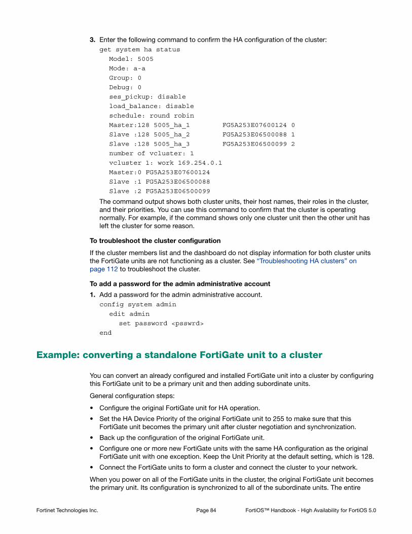
3. Enter the following command to confirm the HA configuration of the cluster:get system ha status
Model: 5005
Mode: a-a
Group: 0
Debug: 0
ses_pickup: disable
load_balance: disable
schedule: round robin
Master:128 5005_ha_1 FG5A253E07600124 0
Slave :128 5005_ha_2 FG5A253E06500088 1
Slave :128 5005_ha_3 FG5A253E06500099 2
number of vcluster: 1
vcluster 1: work 169.254.0.1
Master:0 FG5A253E07600124
Slave :1 FG5A253E06500088
Slave :2 FG5A253E06500099
The command output shows both cluster units, their host names, their roles in the cluster, and their priorities. You can use this command to confirm that the cluster is operating normally. For example, if the command shows only one cluster unit then the other unit has left the cluster for some reason.
To troubleshoot the cluster configuration
If the cluster members list and the dashboard do not display information for both cluster units the FortiGate units are not functioning as a cluster. See “Troubleshooting HA clusters” on page 112 to troubleshoot the cluster.
To add a password for the admin administrative account
1. Add a password for the admin administrative account.config system admin
edit admin
set password <psswrd>
end
Example: converting a standalone FortiGate unit to a cluster
You can convert an already configured and installed FortiGate unit into a cluster by configuring this FortiGate unit to be a primary unit and then adding subordinate units.
General configuration steps:
• Configure the original FortiGate unit for HA operation.
• Set the HA Device Priority of the original FortiGate unit to 255 to make sure that this FortiGate unit becomes the primary unit after cluster negotiation and synchronization.
• Back up the configuration of the original FortiGate unit.
• Configure one or more new FortiGate units with the same HA configuration as the original FortiGate unit with one exception. Keep the Unit Priority at the default setting, which is 128.
• Connect the FortiGate units to form a cluster and connect the cluster to your network.
When you power on all of the FortiGate units in the cluster, the original FortiGate unit becomes the primary unit. Its configuration is synchronized to all of the subordinate units. The entire
Fortinet Technologies Inc. Page 84 FortiOS™ Handbook - High Availability for FortiOS 5.0

cluster now operates with the original FortiGate unit configuration. No further configuration changes are required.
The new FortiGate units must:
• Have the same hardware configuration as the original FortiGate unit. Including the same hard disk configuration and the same AMC cards installed in the same slots.
• Have the same firmware build as the original FortiGate unit.
• Be set to the same operating mode (NAT or Transparent) as the original FortiGate unit.
• Be operating in single VDOM mode.
In addition to one or more new FortiGate units, you need sufficient switches to connect all of the FortiGate interfaces in the cluster. Generally you will need one switch per interface, as it will have to connect that same interface on all cluster units. That is, all port1 interfaces use the port1 switch, port2 interfaces use the port2 switch, and so on. Intelligent switches that can be partitioned can reduce your switch requirements.
Converting a FortiGate unit to a primary unit and adding in the subordinate unit or units results in a brief service interruption as you disconnect and reconnect FortiGate interfaces and as the cluster negotiates. Therefore, conversion should only be done during off peak hours.
To configure the original FortiGate unit for HA operation
1. Connect to the FortiGate unit web-based manager.
2. Go to System > Config > HA.
3. Configure the FortiGate unit for HA operation.
You can make other HA configuration changes after the cluster is operating.
4. Select OK.
The FortiGate unit negotiates to establish an HA cluster. When you select OK you may temporarily lose connectivity with the FortiGate unit as the HA cluster negotiates and because the FGCP changes the MAC address of the FortiGate unit interfaces (see “Cluster virtual MAC addresses” on page 200).
To reconnect sooner, you can update the ARP table of your management PC by deleting the ARP table entry for the FortiGate unit (or just deleting all arp table entries). You may be able to delete the arp table of your management PC from a command prompt using a command similar to arp -d.
Make sure your FortiGate interfaces are configured with static IP addresses. If any interface gets its address using DHCP you will not be able to configure HA.
Mode Active-Active
Device Priority 255
Group Name example4.com
Password HA_pass_4
Fortinet Technologies Inc. Page 85 FortiOS™ Handbook - High Availability for FortiOS 5.0

5. Configure the new FortiGate units with the same HA configuration as the original FortiGate unit. The one exception is to keep the device priorities of the new FortiGate units at 128 to ensure the original FortiGate unit will become the primary unit in the new cluster.
6. Configure the other FortiGate units to the same operation mode as the original FortiGate unit.
There is no need to make any other configuration changes (including network configuration changes) to the other FortiGate units.
7. Optionally power off all of the cluster units.
If you don’t power off all of the units they may not negotiate to form a cluster when they are connected together.
8. Connect the cluster to your network.
For example, for a configuration similar to the FortiGate-620B cluster configuration described in this chapter, see “To connect the cluster to the network” on page 56.
9. Power on all of the cluster units.
As the units start they change their MAC addresses and then negotiate to choose the primary unit and the subordinate units. This negotiation occurs with no user intervention and normally takes less than a minute.
The original the FortiGate unit becomes the primary unit because the device priority of the original FortiGate unit is higher than the device priority of the other FortiGate units. The configuration of the original FortiGate unit is synchronized to all the cluster units. As a result, the cluster is quickly up and running and configured for your network. No further configuration changes are required.
Example: adding a new unit to an operating cluster
This procedure describes how to add a new FortiGate unit to a functioning cluster. Adding a new unit to a cluster does not interrupt the operation of the cluster unless you have to change how the cluster is connected to the network to accommodate the new cluster unit.
You can use this procedure to add as many units as required to the cluster.
To add a new unit to a functioning cluster
1. Install the same firmware build on the new cluster unit as is running on the cluster.
2. Configure the new cluster unit for HA operation with the same HA configuration as the other units in the cluster.
3. If the cluster is running in Transparent mode, change the operating mode of the new cluster unit to Transparent mode.
4. Connect the new cluster unit to the cluster.
5. For example, for a configuration similar to the FortiGate-620B cluster configuration described in this chapter, see “To connect the cluster to the network” on page 56.
Mode Active-Active
Device Priority 128
Group Name example4.com
Password HA_pass_4
Fortinet Technologies Inc. Page 86 FortiOS™ Handbook - High Availability for FortiOS 5.0

6. Power on the new cluster unit.
When the unit starts it negotiates to join the cluster. After it joins the cluster, the cluster synchronizes the new unit configuration with the configuration of the primary unit.
You can add a new unit to a functioning cluster at any time. The new cluster unit must:
• Have the same hardware configuration as the cluster units. Including the same hard disk configuration and the same AMC cards installed in the same slots.
• Have the same firmware build as the cluster.
• Be set to the same operating mode (NAT or Transparent) as the cluster.
• Be operating in single VDOM mode.
Example: replacing a failed cluster unit
This procedure describes how to remove a failed cluster unit from a cluster and add a new one to replace it. You can also use this procedure to remove a failed unit from a cluster, repair it and add it back to the cluster. Replacing a failed does not interrupt the operation of the cluster unless you have to change how the cluster is connected to the network to accommodate the replacement unit.
You can use this procedure to replace more than one cluster unit.
To replace a failed cluster unit
1. Disconnect the failed unit from the cluster and the network.
If you maintain other connections between the network and the still functioning cluster unit or units and between remaining cluster units network traffic will continue to be processed.
2. Repair the failed cluster unit, or obtain a replacement unit with the exact same hardware configuration as the failed cluster unit.
3. Install the same firmware build on the repaired or replacement unit as is running on the cluster.
4. Configure the repaired or replacement unit for HA operation with the same HA configuration as the cluster.
5. If the cluster is running in Transparent mode, change the operating mode of the repaired or replacement cluster unit to Transparent mode.
6. Connect the repaired or replacement cluster unit to the cluster.
For example, for a configuration similar to the FortiGate-620B cluster configuration described in this chapter, see “To connect the cluster to the network” on page 56.
7. Power on the repaired or replacement cluster unit.
When the unit starts it negotiates to join the cluster. After it joins the cluster, the cluster synchronizes the repaired or replacement unit configuration with the configuration of the primary unit.
You can add a repaired or replacement unit to a functioning cluster at any time. The repaired or replacement cluster unit must:
• Have the same hardware configuration as the cluster units. Including the same hard disk configuration and the same AMC cards installed in the same slots.
• Have the same firmware build as the cluster.
• Be set to the same operating mode (NAT or Transparent) as the cluster.
• Be operating in single VDOM mode.
Fortinet Technologies Inc. Page 87 FortiOS™ Handbook - High Availability for FortiOS 5.0
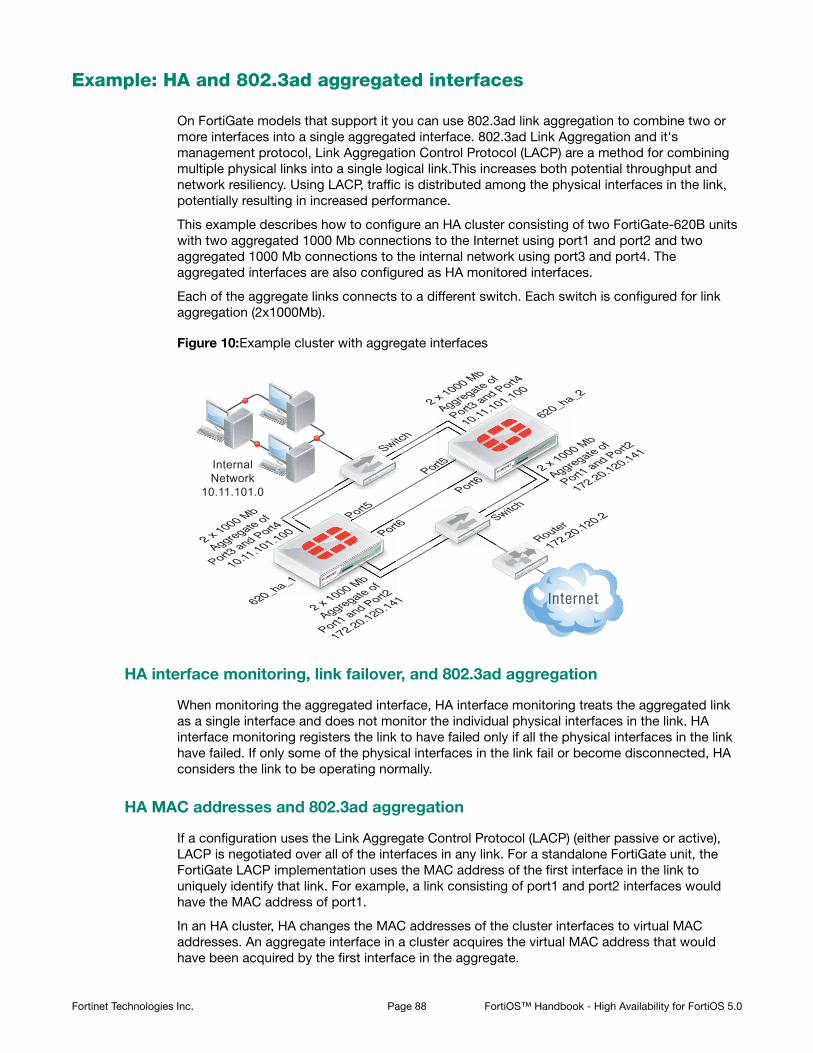
Example: HA and 802.3ad aggregated interfaces
On FortiGate models that support it you can use 802.3ad link aggregation to combine two or more interfaces into a single aggregated interface. 802.3ad Link Aggregation and it's management protocol, Link Aggregation Control Protocol (LACP) are a method for combining multiple physical links into a single logical link.This increases both potential throughput and network resiliency. Using LACP, traffic is distributed among the physical interfaces in the link, potentially resulting in increased performance.
This example describes how to configure an HA cluster consisting of two FortiGate-620B units with two aggregated 1000 Mb connections to the Internet using port1 and port2 and two aggregated 1000 Mb connections to the internal network using port3 and port4. The aggregated interfaces are also configured as HA monitored interfaces.
Each of the aggregate links connects to a different switch. Each switch is configured for link aggregation (2x1000Mb).
Figure 10:Example cluster with aggregate interfaces
HA interface monitoring, link failover, and 802.3ad aggregation
When monitoring the aggregated interface, HA interface monitoring treats the aggregated link as a single interface and does not monitor the individual physical interfaces in the link. HA interface monitoring registers the link to have failed only if all the physical interfaces in the link have failed. If only some of the physical interfaces in the link fail or become disconnected, HA considers the link to be operating normally.
HA MAC addresses and 802.3ad aggregation
If a configuration uses the Link Aggregate Control Protocol (LACP) (either passive or active), LACP is negotiated over all of the interfaces in any link. For a standalone FortiGate unit, the FortiGate LACP implementation uses the MAC address of the first interface in the link to uniquely identify that link. For example, a link consisting of port1 and port2 interfaces would have the MAC address of port1.
In an HA cluster, HA changes the MAC addresses of the cluster interfaces to virtual MAC addresses. An aggregate interface in a cluster acquires the virtual MAC address that would have been acquired by the first interface in the aggregate.
InternalNetwork
10.11.101.0
Router
172.20.120.2Switch
Switch
620_ha_1
620_ha_2
2 x 1000 Mb
Aggregate of
Port1 and Port2
172.20.120.141
2 x 1000 Mb
Aggregate of
Port1 and Port2
172.20.120.141
2 x 1000 Mb
Aggregate of
Port3 and Port4
10.11.101.100
2 x 1000 Mb
Aggregate of
Port3 and Port4
10.11.101.100Port5
Port5
Port6
Port6
S
S
Fortinet Technologies Inc. Page 88 FortiOS™ Handbook - High Availability for FortiOS 5.0
Link aggregation, HA failover performance, and HA mode
To operate an active-active or active-passive cluster with aggregated interfaces and for best performance of a cluster with aggregated interfaces, the switches used to connect the cluster unit aggregated interfaces together should support configuring multiple Link Aggregation (LAG) groups.
For example, the cluster shown in Figure 10 should be configured into two LAG groups on the external switch: one for the port1 and port2 aggregated interface of 620_ha_1 and a second one for the port1 and port2 aggregate interface of 620_ha_2. You should also be able to do the same on the internal switch for the port3 and port4 aggregated interfaces of each cluster unit.
As a result, the subordinate unit aggregated interfaces would participate in LACP negotiation while the cluster is operating. In an active-active mode cluster, packets could be redirected to the subordinate unit interfaces. As well, in active-active or active-passive mode, after a failover the subordinate unit can become a primary unit without having to perform LACP negotiation before it can process traffic. Performing LACP negotiation causes a minor failover delay.
However if you cannot configure multiple LAG groups on the switches, due to the primary and subordinate unit interfaces having the same MAC address, the switch will put all of the interfaces into the same LAG group which would disrupt the functioning of the cluster. To prevent this from happening, you must change the FortiGate aggregated interface configuration to prevent subordinate units from participating in LACP negotiation.
For example, use the following command to prevent subordinate units from participating in LACP negotiation with an aggregate interface named Port1_Port2:
config system interface
edit Port1_Port2
set lacp-ha-slave disable
end
As a result of this setting, subordinate unit aggregated interfaces cannot accept packets. This means that you cannot operate the cluster in active-active mode because in active-active mode the subordinate units must be able to receive and process packets. Also, failover may take longer because after a failover the subordinate unit has to perform LACP negotiation before being able to process network traffic.
Also, it may also be necessary to configure the switch to use Passive or even Static mode for LACP to prevent the switch from sending packets to the subordinate unit interfaces, which won’t be able to process them.
Finally, in some cases depending on the LACP configuration of the switches, you may experience delayed failover if the FortiGate LACP configuration is not compatible with the switch LACP configuration. For example, in some cases setting the FortiGate LACP mode to static reduces the failover delay because the FortiGate unit does not perform LACP negotiation. However there is a potential problem with this configuration because static LACP does not send periodic LAC Protocol Data Unit (LACPDU) packets to test the connections. So a non-physical failure (for example, if a device is not responding because its too busy) may not be detected and packets could be lost or delayed.
General configuration steps
The section includes web-based manager and CLI procedures. These procedures assume that the FortiGate-620B units are running the same FortiOS firmware build and are set to the factory default configuration.
General configuration steps
1. Configure the FortiGate units for HA operation.
Fortinet Technologies Inc. Page 89 FortiOS™ Handbook - High Availability for FortiOS 5.0

• Change each unit’s host name.
• Configure HA.
2. Connect the cluster to the network.
3. View cluster status.
4. Add basic configuration settings and configure the aggregated interfaces.
• Add a password for the admin administrative account.
• Add the aggregated interfaces.
• Disable lacp-ha-slave so that the subordinate unit does not send LACP packets.
• Add a default route.
You could also configure aggregated interfaces in each FortiGate unit before the units form a cluster.
5. Configure HA port monitoring for the aggregated interfaces.
Configuring active-passive HA cluster that includes aggregated interfaces - web-based manager
These procedures assume you are starting with two FortiGate-620B units with factory default settings.
To configure the FortiGate-620B units for HA operation
1. Power on the first FortiGate-620B unit and log into the web-based manager.
2. On the System Information dashboard widget, beside Host Name select Change.
3. Enter a new Host Name for this FortiGate unit.
4. Select OK.
5. Go to System > Config > HA and change the following settings.
Since port3 and port4 will be used for a aggregated interface, you must change the HA heartbeat configuration to not use those interfaces.
6. Select OK.
The FortiGate unit negotiates to establish an HA cluster. When you select OK you may temporarily lose connectivity with the FortiGate unit as the HA cluster negotiates and the FGCP changes the MAC address of the FortiGate unit interfaces (see “Cluster virtual MAC addresses” on page 200). The MAC addresses of the FortiGate-620B interfaces change to the following virtual MAC addresses:
New Name 620_ha_1
Mode Active-Passive
Group Name example5.com
Password HA_pass_5
Heartbeat Interface
Enable Priority
port5 Select 50
port6 Select 50
Fortinet Technologies Inc. Page 90 FortiOS™ Handbook - High Availability for FortiOS 5.0

• port1 interface virtual MAC: 00-09-0f-09-00-00
• port10 interface virtual MAC: 00-09-0f-09-00-01
• port11 interface virtual MAC: 00-09-0f-09-00-02
• port12 interface virtual MAC: 00-09-0f-09-00-03
• port13 interface virtual MAC: 00-09-0f-09-00-04
• port14 interface virtual MAC: 00-09-0f-09-00-05
• port15 interface virtual MAC: 00-09-0f-09-00-06
• port16 interface virtual MAC: 00-09-0f-09-00-07
• port17 interface virtual MAC: 00-09-0f-09-00-08
• port18 interface virtual MAC: 00-09-0f-09-00-09
• port19 interface virtual MAC: 00-09-0f-09-00-0a
• port2 interface virtual MAC: 00-09-0f-09-00-0b
• port20 interface virtual MAC: 00-09-0f-09-00-0c
• port3 interface virtual MAC: 00-09-0f-09-00-0d
• port4 interface virtual MAC: 00-09-0f-09-00-0e
• port5 interface virtual MAC: 00-09-0f-09-00-0f
• port6 interface virtual MAC: 00-09-0f-09-00-10
• port7 interface virtual MAC: 00-09-0f-09-00-11
• port8 interface virtual MAC: 00-09-0f-09-00-12
• port9 interface virtual MAC: 00-09-0f-09-00-13
To reconnect sooner, you can update the ARP table of your management PC by deleting the ARP table entry for the FortiGate unit (or just deleting all arp table entries). You may be able to delete the arp table of your management PC from a command prompt using a command similar to arp -d.
You can use the get hardware nic (or diagnose hardware deviceinfo nic) CLI command to view the virtual MAC address of any FortiGate unit interface. For example, use the following command to view the port1 interface virtual MAC address (Current_HWaddr) and the port1 permanent MAC address (Permanent_HWaddr):get hardware nic port1
.
.
.
MAC: 00:09:0f:09:00:00
Permanent_HWaddr: 02:09:0f:78:18:c9
.
.
.
7. Power off the first FortiGate unit.
8. Repeat these steps for the second FortiGate unit.
Set the second FortiGate unit host name to:
New Name 620_ha_2
Fortinet Technologies Inc. Page 91 FortiOS™ Handbook - High Availability for FortiOS 5.0

To connect the cluster to the network
1. Connect the port1 and port2 interfaces of 620_ha_1 and 620_ha_2 to a switch connected to the Internet.
Configure the switch so that the port1 and port2 of 620_ha_1 make up an aggregated interface and port1 and port2 of 620_ha_2 make up a second aggregated interface.
2. Connect the port3 and port4 interfaces of 620_ha_1 and 620_ha_2 to a switch connected to the internal network.
Configure the switch so that the port3 and port4 of 620_ha_1 make up an aggregated interface and port3 and port4 of 620_ha_2 make up another aggregated interface.
3. Connect the port5 interfaces of 620_ha_1 and 620_ha_2 together. You can use a crossover Ethernet cable or regular Ethernet cables and a switch.
4. Connect the port5 interfaces of the cluster units together. You can use a crossover Ethernet cable or regular Ethernet cables and a switch.
5. Power on the cluster units.
The units negotiate to choose the primary unit and the subordinate unit. This negotiation occurs with no user intervention and normally takes less than a minute.
When negotiation is complete, the cluster is ready to be configured for your network.
To view cluster status
Use the following steps to view the cluster dashboard and cluster members list to confirm that the cluster units are operating as a cluster.
1. View the system dashboard.
The System Information dashboard widget shows the Cluster Name (example5.com) and the host names and serial numbers of the Cluster Members. The Unit Operation widget shows multiple cluster units.
2. Go to System > Config > HA to view the cluster members list.
The list shows two cluster units, their host names, their roles in the cluster, and their priorities. You can use this list to confirm that the cluster is operating normally.
To troubleshoot the cluster configuration
If the cluster members list and the dashboard do not display information for both cluster units, the FortiGate units are not functioning as a cluster. See “Troubleshooting HA clusters” on page 112 to troubleshoot the cluster.
To add basic configuration settings and the aggregate interfaces
Use the following steps to add a few basic configuration settings.
1. Log into the cluster web-based manager.
2. Go to System > Admin > Administrators.
3. For admin, select the Change Password icon.
4. Enter and confirm a new password.
5. Select OK.
6. Go to Router > Static > Static Routes and temporarily delete the default route.
You cannot add an interface to a aggregated interface if any settings (such as the default route) are configured for it.
7. Go to System > Network > Interfaces and select Create New to add the aggregate interface to connect to the Internet.
Fortinet Technologies Inc. Page 92 FortiOS™ Handbook - High Availability for FortiOS 5.0

8. Set Type to 802.3ad Aggregate and configure the aggregate interface to be connected to the Internet:
9. Select OK.
10.Select Create New to add the aggregate interface to connect to the internal network.
11.Set Type to 802.3ad Aggregate and configure the aggregate interface to be connected to the Internet:
12.Select OK.
The virtual MAC addresses of the FortiGate-620B interfaces change to the following. Note that port1 and port2 both have the port1 virtual MAC address and port3 and port4 both have the port3 virtual MAC address:
• port1 interface virtual MAC: 00-09-0f-09-00-00
• port10 interface virtual MAC: 00-09-0f-09-00-01
• port11 interface virtual MAC: 00-09-0f-09-00-02
• port12 interface virtual MAC: 00-09-0f-09-00-03
• port13 interface virtual MAC: 00-09-0f-09-00-04
• port14 interface virtual MAC: 00-09-0f-09-00-05
• port15 interface virtual MAC: 00-09-0f-09-00-06
• port16 interface virtual MAC: 00-09-0f-09-00-07
• port17 interface virtual MAC: 00-09-0f-09-00-08
• port18 interface virtual MAC: 00-09-0f-09-00-09
• port19 interface virtual MAC: 00-09-0f-09-00-0a
• port2 interface virtual MAC: 00-09-0f-09-00-00 (same as port1)
• port20 interface virtual MAC: 00-09-0f-09-00-0c
• port3 interface virtual MAC: 00-09-0f-09-00-0d
• port4 interface virtual MAC: 00-09-0f-09-00-0d (same as port3)
• port5 interface virtual MAC: 00-09-0f-09-00-0f
• port6 interface virtual MAC: 00-09-0f-09-00-10
• port7 interface virtual MAC: 00-09-0f-09-00-11
• port8 interface virtual MAC: 00-09-0f-09-00-12
Name Port1_Port2
Physical Interface Members
Selected Interfaces port1, port2
IP/Netmask 172.20.120.141/24
Name Port3_Port4
Physical Interface Members
Selected Interfaces port3, port4
IP/Netmask 10.11.101.100/24
Administrative Access HTTPS, PING, SSH
Fortinet Technologies Inc. Page 93 FortiOS™ Handbook - High Availability for FortiOS 5.0

• port9 interface virtual MAC: 00-09-0f-09-00-13
13.Connect to the CLI and enter the following command to disable sending LACP packets from the subordinate unit:config system interface
edit Port1_Port2
set lacp-ha-slave disable
next
edit Port3_Port4
set lacp-ha-slave disable
end
14.Go to Router > Static > Static Routes.
15.Add the default route.
16.Select OK.
To configure HA port monitoring for the aggregate interfaces
1. Go to System > Config > HA.
2. In the cluster members list, edit the primary unit.
3. Configure the following port monitoring for the aggregate interfaces:
4. Select OK.
Configuring active-passive HA cluster that includes aggregate interfaces - CLI
These procedures assume you are starting with two FortiGate-620B units with factory default settings.
To configure the FortiGate-620B units for HA operation
1. Power on the first FortiGate-620B unit and log into the CLI.
2. Change the host name for this FortiGate unit:config system global
set hostname 620_ha_1
end
Destination IP/Mask 0.0.0.0/0.0.0.0
Gateway 172.20.120.2
Device Port1_Port2
Distance 10
Port Monitor
Port1_Port2 Select
Port3_Port4 Select
Fortinet Technologies Inc. Page 94 FortiOS™ Handbook - High Availability for FortiOS 5.0

3. Configure HA settings.config system ha
set mode a-p
set group-name example5.com
set password HA_pass_5
set hbdev port5 50 port6 50
end
Since port3 and port4 will be used for an aggregated interface, you must change the HA heartbeat configuration.
The FortiGate unit negotiates to establish an HA cluster. You may temporarily lose connectivity with the FortiGate unit as the HA cluster negotiates and the FGCP changes the MAC address of the FortiGate unit interfaces (see “Cluster virtual MAC addresses” on page 200). The MAC addresses of the FortiGate-620B interfaces change to the following virtual MAC addresses:
• port1 interface virtual MAC: 00-09-0f-09-00-00
• port10 interface virtual MAC: 00-09-0f-09-00-01
• port11 interface virtual MAC: 00-09-0f-09-00-02
• port12 interface virtual MAC: 00-09-0f-09-00-03
• port13 interface virtual MAC: 00-09-0f-09-00-04
• port14 interface virtual MAC: 00-09-0f-09-00-05
• port15 interface virtual MAC: 00-09-0f-09-00-06
• port16 interface virtual MAC: 00-09-0f-09-00-07
• port17 interface virtual MAC: 00-09-0f-09-00-08
• port18 interface virtual MAC: 00-09-0f-09-00-09
• port19 interface virtual MAC: 00-09-0f-09-00-0a
• port2 interface virtual MAC: 00-09-0f-09-00-0b
• port20 interface virtual MAC: 00-09-0f-09-00-0c
• port3 interface virtual MAC: 00-09-0f-09-00-0d
• port4 interface virtual MAC: 00-09-0f-09-00-0e
• port5 interface virtual MAC: 00-09-0f-09-00-0f
• port6 interface virtual MAC: 00-09-0f-09-00-10
• port7 interface virtual MAC: 00-09-0f-09-00-11
• port8 interface virtual MAC: 00-09-0f-09-00-12
• port9 interface virtual MAC: 00-09-0f-09-00-13
To reconnect sooner, you can update the ARP table of your management PC by deleting the ARP table entry for the FortiGate unit (or just deleting all arp table entries). You may be able to delete the arp table of your management PC from a command prompt using a command similar to arp -d.
You can use the get hardware nic (or diagnose hardware deviceinfo nic) CLI command to view the virtual MAC address of any FortiGate unit interface. For example, use
Fortinet Technologies Inc. Page 95 FortiOS™ Handbook - High Availability for FortiOS 5.0

the following command to view the port1 interface virtual MAC address (Current_HWaddr) and the port1 permanent MAC address (Permanent_HWaddr):get hardware nic port1
.
.
.
MAC: 00:09:0f:09:00:00
Permanent_HWaddr: 02:09:0f:78:18:c9
.
.
.
4. Display the HA configuration (optional).get system ha
group-id : 0
group-name : example5.com
mode : a-p
password : *
hbdev : "port5" 50 "port6" 50
session-sync-dev :
route-ttl : 10
route-wait : 0
route-hold : 10
sync-config : enable
encryption : disable
authentication : disable
hb-interval : 2
hb-lost-threshold : 20
helo-holddown : 20
arps : 5
arps-interval : 8
session-pickup : disable
link-failed-signal : disable
uninterruptible-upgrade: enable
ha-mgmt-status : disable
ha-eth-type : 8890
hc-eth-type : 8891
l2ep-eth-type : 8893
subsecond : disable
vcluster2 : disable
vcluster-id : 1
override : disable
priority : 128
monitor :
pingserver-monitor-interface:
pingserver-failover-threshold: 0
pingserver-flip-timeout: 60
vdom : "root"
Fortinet Technologies Inc. Page 96 FortiOS™ Handbook - High Availability for FortiOS 5.0
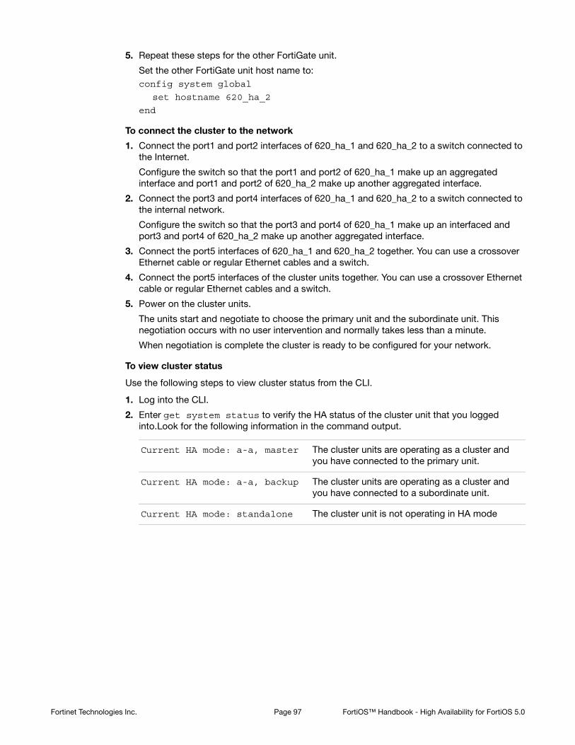
5. Repeat these steps for the other FortiGate unit.
Set the other FortiGate unit host name to:config system global
set hostname 620_ha_2
end
To connect the cluster to the network
1. Connect the port1 and port2 interfaces of 620_ha_1 and 620_ha_2 to a switch connected to the Internet.
Configure the switch so that the port1 and port2 of 620_ha_1 make up an aggregated interface and port1 and port2 of 620_ha_2 make up another aggregated interface.
2. Connect the port3 and port4 interfaces of 620_ha_1 and 620_ha_2 to a switch connected to the internal network.
Configure the switch so that the port3 and port4 of 620_ha_1 make up an interfaced and port3 and port4 of 620_ha_2 make up another aggregated interface.
3. Connect the port5 interfaces of 620_ha_1 and 620_ha_2 together. You can use a crossover Ethernet cable or regular Ethernet cables and a switch.
4. Connect the port5 interfaces of the cluster units together. You can use a crossover Ethernet cable or regular Ethernet cables and a switch.
5. Power on the cluster units.
The units start and negotiate to choose the primary unit and the subordinate unit. This negotiation occurs with no user intervention and normally takes less than a minute.
When negotiation is complete the cluster is ready to be configured for your network.
To view cluster status
Use the following steps to view cluster status from the CLI.
1. Log into the CLI.
2. Enter get system status to verify the HA status of the cluster unit that you logged into.Look for the following information in the command output.
Current HA mode: a-a, master The cluster units are operating as a cluster and you have connected to the primary unit.
Current HA mode: a-a, backup The cluster units are operating as a cluster and you have connected to a subordinate unit.
Current HA mode: standalone The cluster unit is not operating in HA mode
Fortinet Technologies Inc. Page 97 FortiOS™ Handbook - High Availability for FortiOS 5.0

3. Enter the following command to confirm the HA configuration of the cluster:get system ha status
Model: 620
Mode: a-a
Group: 0
Debug: 0
ses_pickup: disable
Master:128 620_ha_2 FG600B3908600825 0
Slave :128 620_ha_1 FG600B3908600705 1
number of vcluster: 1
vcluster 1: work 169.254.0.1
Master:0 FG600B3908600825
Slave :1 FG600B3908600705
The command output shows both cluster units, their host names, their roles in the cluster, and their priorities. You can use this command to confirm that the cluster is operating normally. For example, if the command shows only one cluster unit then the other unit has left the cluster for some reason.
To troubleshoot the cluster configuration
If the cluster members list and the dashboard do not display information for both cluster units the FortiGate units are not functioning as a cluster. See “Troubleshooting HA clusters” on page 112 to troubleshoot the cluster.
To add basic configuration settings and the aggregate interfaces
Use the following steps to add a few basic configuration settings and the aggregate interfaces.
1. Add a password for the admin administrative account.config system admin
edit admin
set password <psswrd>
end
2. Temporarily delete the default route.
You cannot add an interface to an aggregate interface if any settings (such as the default route) are configured for it. In this example the index of the default route is 1.config router static
delete 1
end
Fortinet Technologies Inc. Page 98 FortiOS™ Handbook - High Availability for FortiOS 5.0
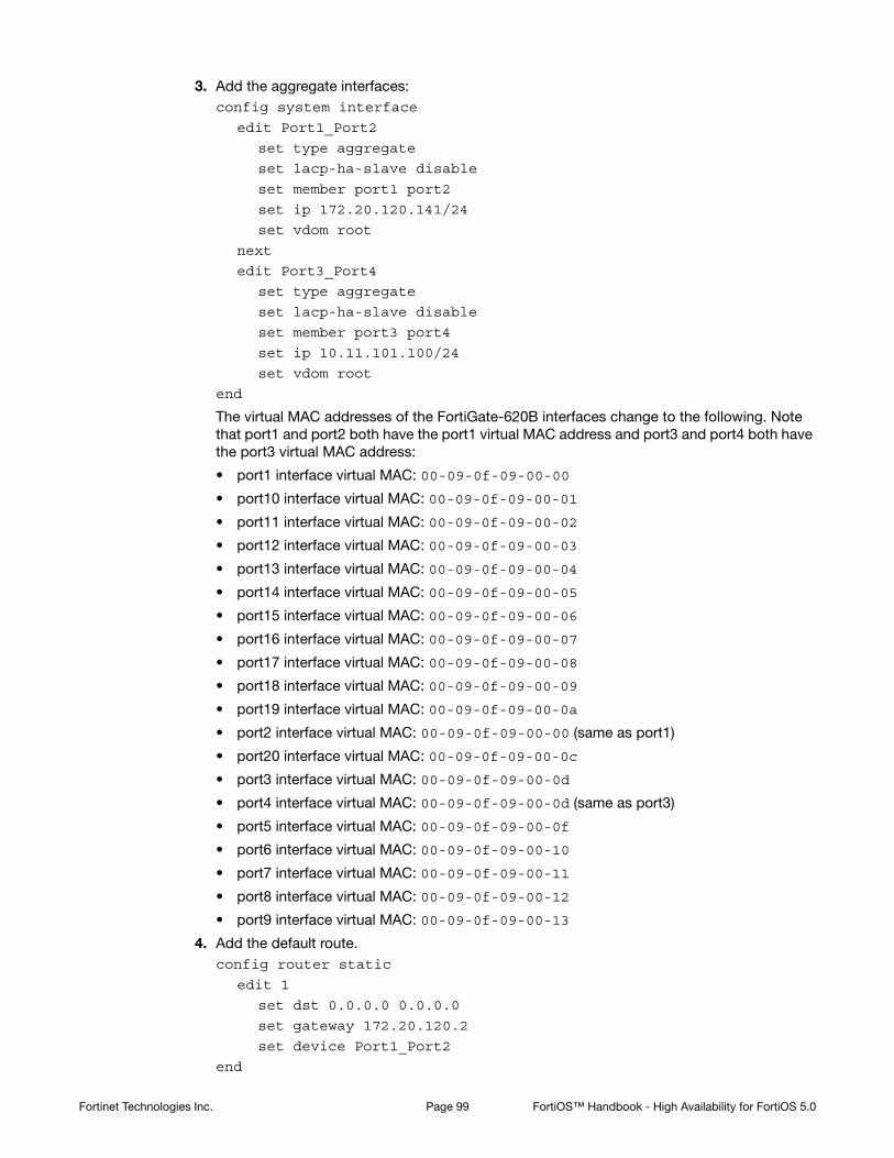
3. Add the aggregate interfaces:config system interface
edit Port1_Port2
set type aggregate
set lacp-ha-slave disable
set member port1 port2
set ip 172.20.120.141/24
set vdom root
next
edit Port3_Port4
set type aggregate
set lacp-ha-slave disable
set member port3 port4
set ip 10.11.101.100/24
set vdom root
end
The virtual MAC addresses of the FortiGate-620B interfaces change to the following. Note that port1 and port2 both have the port1 virtual MAC address and port3 and port4 both have the port3 virtual MAC address:
• port1 interface virtual MAC: 00-09-0f-09-00-00
• port10 interface virtual MAC: 00-09-0f-09-00-01
• port11 interface virtual MAC: 00-09-0f-09-00-02
• port12 interface virtual MAC: 00-09-0f-09-00-03
• port13 interface virtual MAC: 00-09-0f-09-00-04
• port14 interface virtual MAC: 00-09-0f-09-00-05
• port15 interface virtual MAC: 00-09-0f-09-00-06
• port16 interface virtual MAC: 00-09-0f-09-00-07
• port17 interface virtual MAC: 00-09-0f-09-00-08
• port18 interface virtual MAC: 00-09-0f-09-00-09
• port19 interface virtual MAC: 00-09-0f-09-00-0a
• port2 interface virtual MAC: 00-09-0f-09-00-00 (same as port1)
• port20 interface virtual MAC: 00-09-0f-09-00-0c
• port3 interface virtual MAC: 00-09-0f-09-00-0d
• port4 interface virtual MAC: 00-09-0f-09-00-0d (same as port3)
• port5 interface virtual MAC: 00-09-0f-09-00-0f
• port6 interface virtual MAC: 00-09-0f-09-00-10
• port7 interface virtual MAC: 00-09-0f-09-00-11
• port8 interface virtual MAC: 00-09-0f-09-00-12
• port9 interface virtual MAC: 00-09-0f-09-00-13
4. Add the default route.config router static
edit 1
set dst 0.0.0.0 0.0.0.0
set gateway 172.20.120.2
set device Port1_Port2
end
Fortinet Technologies Inc. Page 99 FortiOS™ Handbook - High Availability for FortiOS 5.0

To configure HA port monitoring for the aggregate interfaces
1. Configure HA port monitoring for the aggregate interfaces.config system ha
set monitor Port1_Port2 Port3_Port4
end
Example: HA and redundant interfaces
On FortiGate models that support it you can combine two or more interfaces into a single redundant interface. A redundant interface consists of two or more physical interfaces. Traffic is processed by the first physical interface in the redundant interface. If that physical interface fails, traffic fails over to the next physical interface. Redundant interfaces don’t have the benefit of improved performance that aggregate interfaces can have, but they do provide failover if a physical interface fails or is disconnected.
Figure 11:Example cluster with a redundant interfaces
This example describes how to configure an HA cluster consisting of two FortiGate-620B units with a a redundant interface connection to the Internet and to an internal network. The connection to the Internet uses port1 and port2. The connection to the internal network uses port3 and port4. The HA heartbeat uses port5 and port6.
The redundant interfaces are also configured as HA monitored interfaces.
HA interface monitoring, link failover, and redundant interfaces
HA interface monitoring monitors the redundant interface as a single interface and does not monitor the individual physical interfaces in the redundant interface. HA interface monitoring registers the redundant interface to have failed only if all the physical interfaces in the redundant interface have failed. If only some of the physical interfaces in the redundant interface fail or become disconnected, HA considers the redundant interface to be operating normally.
InternalNetwork
10.11.101.0
Router
172.20.120.2Switch
Switch
620_ha_1
620_ha_2
Redundant interfa
ce
Port1 and Port2
172.20.120.141
Redundant interfa
ce
Port1 and Port2
172.20.120.141
Redundant interfa
ce
Port3 and Port4
10.11.101.100
Redundant interfa
ce
Port3 and Port4
10.11.101.100
Port5
Port5
Port6
Port6
S
S
Fortinet Technologies Inc. Page 100 FortiOS™ Handbook - High Availability for FortiOS 5.0

HA MAC addresses and redundant interfaces
For a standalone FortiGate unit a redundant interface has the MAC address of the first physical interface added to the redundant interface configuration. A redundant interface consisting of port1 and port2 would have the MAC address of port1.
In an HA cluster, HA changes the MAC addresses of the cluster interfaces to virtual MAC addresses. A redundant interface in a cluster acquires the virtual MAC address that would have been acquired by the first physical interface added to the redundant interface configuration.
Connecting multiple redundant interfaces to one switch while operating in active-passive HA mode
HA assigns the same virtual MAC addresses to the subordinate unit interfaces as are assigned to the corresponding primary unit interfaces. Consider a cluster of two FortiGate units operating in active-passive mode with a redundant interface consisting of port1 and port2. You can connect multiple redundant interfaces to the same switch if you configure the switch so that it defines multiple separate redundant interfaces and puts the redundant interfaces of each cluster unit into separate redundant interfaces. In this configuration, each cluster unit forms a separate redundant interface with the switch.
However, if the switch is configured with a single four-port redundant interface configuration, because the same MAC addresses are being used by both cluster units, the switch adds all four interfaces (port1 and port2 from the primary unit and port1 and port2 from the subordinate unit) to the same redundant interface.
To avoid unpredictable results, when you connect a switch to multiple redundant interfaces in an active-passive cluster you should configure separate redundant interfaces on the switch; one for each cluster unit.
Connecting multiple redundant interfaces to one switch while operating in active-active HA mode
In an active-active cluster, all cluster units send and receive packets. To operate a cluster with redundant interfaces in active-active mode, with multiple redundant interfaces connected to the same switch, you must separate the redundant interfaces of each cluster unit into different redundant interfaces on the connecting switch.
General configuration steps
The section includes web-based manager and CLI procedures. These procedures assume that the FortiGate-620B units are running the same FortiOS firmware build and are set to the factory default configuration.
General configuration steps
1. Configure the FortiGate units for HA operation.
• Change each unit’s host name.
• Configure HA.
2. Connect the cluster to the network.
3. View cluster status.
4. Add basic configuration settings and configure the redundant interfaces.
• Add a password for the admin administrative account.
• Add the redundant interfaces.
Fortinet Technologies Inc. Page 101 FortiOS™ Handbook - High Availability for FortiOS 5.0
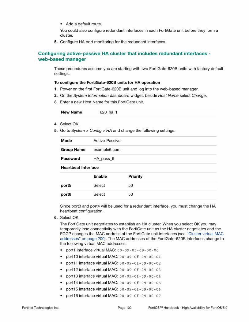
• Add a default route.
You could also configure redundant interfaces in each FortiGate unit before they form a cluster.
5. Configure HA port monitoring for the redundant interfaces.
Configuring active-passive HA cluster that includes redundant interfaces - web-based manager
These procedures assume you are starting with two FortiGate-620B units with factory default settings.
To configure the FortiGate-620B units for HA operation
1. Power on the first FortiGate-620B unit and log into the web-based manager.
2. On the System Information dashboard widget, beside Host Name select Change.
3. Enter a new Host Name for this FortiGate unit.
4. Select OK.
5. Go to System > Config > HA and change the following settings.
Since port3 and port4 will be used for a redundant interface, you must change the HA heartbeat configuration.
6. Select OK.
The FortiGate unit negotiates to establish an HA cluster. When you select OK you may temporarily lose connectivity with the FortiGate unit as the HA cluster negotiates and the FGCP changes the MAC address of the FortiGate unit interfaces (see “Cluster virtual MAC addresses” on page 200). The MAC addresses of the FortiGate-620B interfaces change to the following virtual MAC addresses:
• port1 interface virtual MAC: 00-09-0f-09-00-00
• port10 interface virtual MAC: 00-09-0f-09-00-01
• port11 interface virtual MAC: 00-09-0f-09-00-02
• port12 interface virtual MAC: 00-09-0f-09-00-03
• port13 interface virtual MAC: 00-09-0f-09-00-04
• port14 interface virtual MAC: 00-09-0f-09-00-05
• port15 interface virtual MAC: 00-09-0f-09-00-06
• port16 interface virtual MAC: 00-09-0f-09-00-07
New Name 620_ha_1
Mode Active-Passive
Group Name example6.com
Password HA_pass_6
Heartbeat Interface
Enable Priority
port5 Select 50
port6 Select 50
Fortinet Technologies Inc. Page 102 FortiOS™ Handbook - High Availability for FortiOS 5.0

• port17 interface virtual MAC: 00-09-0f-09-00-08
• port18 interface virtual MAC: 00-09-0f-09-00-09
• port19 interface virtual MAC: 00-09-0f-09-00-0a
• port2 interface virtual MAC: 00-09-0f-09-00-0b
• port20 interface virtual MAC: 00-09-0f-09-00-0c
• port3 interface virtual MAC: 00-09-0f-09-00-0d
• port4 interface virtual MAC: 00-09-0f-09-00-0e
• port5 interface virtual MAC: 00-09-0f-09-00-0f
• port6 interface virtual MAC: 00-09-0f-09-00-10
• port7 interface virtual MAC: 00-09-0f-09-00-11
• port8 interface virtual MAC: 00-09-0f-09-00-12
• port9 interface virtual MAC: 00-09-0f-09-00-13
To reconnect sooner, you can update the ARP table of your management PC by deleting the ARP table entry for the FortiGate unit (or just deleting all arp table entries). You may be able to delete the arp table of your management PC from a command prompt using a command similar to arp -d.
You can use the get hardware nic (or diagnose hardware deviceinfo nic) CLI command to view the virtual MAC address of any FortiGate unit interface. For example, use the following command to view the port1 interface virtual MAC address (Current_HWaddr) and the port1 permanent MAC address (Permanent_HWaddr):get hardware nic port1
.
.
.
MAC: 00:09:0f:09:00:00
Permanent_HWaddr: 02:09:0f:78:18:c9
.
.
.
7. Power off the first FortiGate unit.
8. Repeat these steps for the second FortiGate unit.
Set the second FortiGate unit host name to:
To connect the cluster to the network
1. Connect the port1 and port2 interfaces of 620_ha_1 and 620_ha_2 to a switch connected to the Internet.
Configure the switch so that the port1 and port2 of 620_ha_1 make up a redundant interface and port1 and port2 of 620_ha_2 make up another redundant interface.
2. Connect the port3 and port4 interfaces of 620_ha_1 and 620_ha_2 to a switch connected to the internal network.
Configure the switch so that the port3 and port4 of 620_ha_1 make up a redundant interface and port3 and port4 of 620_ha_2 make up another redundant interface.
3. Connect the port5 interfaces of 620_ha_1 and 620_ha_2 together. You can use a crossover Ethernet cable or regular Ethernet cables and a switch.
New Name 620_ha_2
Fortinet Technologies Inc. Page 103 FortiOS™ Handbook - High Availability for FortiOS 5.0

4. Connect the port5 interfaces of the cluster units together. You can use a crossover Ethernet cable or regular Ethernet cables and a switch.
5. Power on the cluster units.
The units start and negotiate to choose the primary unit and the subordinate unit. This negotiation occurs with no user intervention and normally takes less than a minute.
When negotiation is complete the cluster is ready to be configured for your network.
To view cluster status
Use the following steps to view the cluster dashboard and cluster members list to confirm that the cluster units are operating as a cluster.
1. View the system dashboard.
The System Information dashboard widget shows the Cluster Name (example5.com) and the host names and serial numbers of the Cluster Members. The Unit Operation widget shows multiple cluster units.
2. Go to System > Config > HA to view the cluster members list.
The list shows two cluster units, their host names, their roles in the cluster, and their priorities. You can use this list to confirm that the cluster is operating normally.
To troubleshoot the cluster configuration
If the cluster members list and the dashboard do not display information for both cluster units the FortiGate units are not functioning as a cluster. See “Troubleshooting HA clusters” on page 112 to troubleshoot the cluster.
To add basic configuration settings and the redundant interfaces
Use the following steps to add a few basic configuration settings.
1. Log into the cluster web-based manager.
2. Go to System > Admin > Administrators.
3. For admin, select the Change Password icon
4. Enter and confirm a new password.
5. Select OK.
6. Go to Router > Static > Static Routes and temporarily delete the default route.
You cannot add an interface to a redundant interface if any settings (such as the default route) are configured for it.
7. Go to System > Network > Interfaces and select Create New to add the redundant interface to connect to the Internet.
8. Set Type to Redundant Interface and configure the redundant interface to be connected to the Internet:
9. Select OK.
10.Select Create New to add the redundant interface to connect to the internal network.
Name Port1_Port2
Physical Interface Members
Selected Interfaces port1, port2
IP/Netmask 172.20.120.141/24
Fortinet Technologies Inc. Page 104 FortiOS™ Handbook - High Availability for FortiOS 5.0

11.Set Type to Redundant Interface and configure the redundant interface to be connected to the Internet:
12.Select OK.
The virtual MAC addresses of the FortiGate-620B interfaces change to the following. Note that port1 and port2 both have the port1 virtual MAC address and port3 and port4 both have the port3 virtual MAC address:
• port1 interface virtual MAC: 00-09-0f-09-00-00
• port10 interface virtual MAC: 00-09-0f-09-00-01
• port11 interface virtual MAC: 00-09-0f-09-00-02
• port12 interface virtual MAC: 00-09-0f-09-00-03
• port13 interface virtual MAC: 00-09-0f-09-00-04
• port14 interface virtual MAC: 00-09-0f-09-00-05
• port15 interface virtual MAC: 00-09-0f-09-00-06
• port16 interface virtual MAC: 00-09-0f-09-00-07
• port17 interface virtual MAC: 00-09-0f-09-00-08
• port18 interface virtual MAC: 00-09-0f-09-00-09
• port19 interface virtual MAC: 00-09-0f-09-00-0a
• port2 interface virtual MAC: 00-09-0f-09-00-00 (same as port1)
• port20 interface virtual MAC: 00-09-0f-09-00-0c
• port3 interface virtual MAC: 00-09-0f-09-00-0d
• port4 interface virtual MAC: 00-09-0f-09-00-0d (same as port3)
• port5 interface virtual MAC: 00-09-0f-09-00-0f
• port6 interface virtual MAC: 00-09-0f-09-00-10
• port7 interface virtual MAC: 00-09-0f-09-00-11
• port8 interface virtual MAC: 00-09-0f-09-00-12
• port9 interface virtual MAC: 00-09-0f-09-00-13
13.Go to Router > Static > Static Routes.
14.Add the default route.
15.Select OK.
Name Port3_Port4
Physical Interface Members
Selected Interfaces port3, port4
IP/Netmask 10.11.101.100/24
Administrative Access HTTPS, PING, SSH
Destination IP/Mask 0.0.0.0/0.0.0.0
Gateway 172.20.120.2
Device Port1_Port2
Distance 10
Fortinet Technologies Inc. Page 105 FortiOS™ Handbook - High Availability for FortiOS 5.0

To configure HA port monitoring for the redundant interfaces
1. Go to System > Config > HA.
2. In the cluster members list, edit the primary unit.
3. Configure the following port monitoring for the redundant interfaces:
4. Select OK.
Configuring active-passive HA cluster that includes redundant interfaces - CLI
These procedures assume you are starting with two FortiGate-620B units with factory default settings.
To configure the FortiGate-620B units for HA operation
1. Power on the first FortiGate-620B unit and log into the CLI.
2. Change the host name for this FortiGate unit:config system global
set hostname 620_ha_1
end
3. Configure HA settings.config system ha
set mode a-p
set group-name example6.com
set password HA_pass_6
set hbdev port5 50 port6 50
end
Since port3 and port4 will be used for a redundant interface, you must change the HA heartbeat configuration.
The FortiGate unit negotiates to establish an HA cluster. You may temporarily lose connectivity with the FortiGate unit as the HA cluster negotiates and the FGCP changes the MAC address of the FortiGate unit interfaces (see “Cluster virtual MAC addresses” on page 200). The MAC addresses of the FortiGate-620B interfaces change to the following virtual MAC addresses:
• port1 interface virtual MAC: 00-09-0f-09-00-00
• port10 interface virtual MAC: 00-09-0f-09-00-01
• port11 interface virtual MAC: 00-09-0f-09-00-02
• port12 interface virtual MAC: 00-09-0f-09-00-03
• port13 interface virtual MAC: 00-09-0f-09-00-04
• port14 interface virtual MAC: 00-09-0f-09-00-05
• port15 interface virtual MAC: 00-09-0f-09-00-06
• port16 interface virtual MAC: 00-09-0f-09-00-07
• port17 interface virtual MAC: 00-09-0f-09-00-08
• port18 interface virtual MAC: 00-09-0f-09-00-09
• port19 interface virtual MAC: 00-09-0f-09-00-0a
Port Monitor
Port1_Port2 Select
Port3_Port4 Select
Fortinet Technologies Inc. Page 106 FortiOS™ Handbook - High Availability for FortiOS 5.0

• port2 interface virtual MAC: 00-09-0f-09-00-0b
• port20 interface virtual MAC: 00-09-0f-09-00-0c
• port3 interface virtual MAC: 00-09-0f-09-00-0d
• port4 interface virtual MAC: 00-09-0f-09-00-0e
• port5 interface virtual MAC: 00-09-0f-09-00-0f
• port6 interface virtual MAC: 00-09-0f-09-00-10
• port7 interface virtual MAC: 00-09-0f-09-00-11
• port8 interface virtual MAC: 00-09-0f-09-00-12
• port9 interface virtual MAC: 00-09-0f-09-00-13
To reconnect sooner, you can update the ARP table of your management PC by deleting the ARP table entry for the FortiGate unit (or just deleting all arp table entries). You may be able to delete the arp table of your management PC from a command prompt using a command similar to arp -d.
You can use the get hardware nic (or diagnose hardware deviceinfo nic) CLI command to view the virtual MAC address of any FortiGate unit interface. For example, use the following command to view the port1 interface virtual MAC address (Current_HWaddr) and the port1 permanent MAC address (Permanent_HWaddr):get hardware nic port1
.
.
.
MAC: 00:09:0f:09:00:00
Permanent_HWaddr: 02:09:0f:78:18:c9
.
.
.
Fortinet Technologies Inc. Page 107 FortiOS™ Handbook - High Availability for FortiOS 5.0
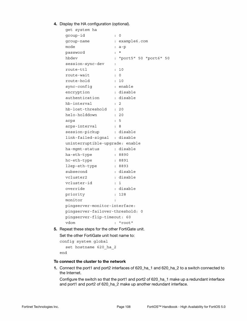
4. Display the HA configuration (optional).get system ha
group-id : 0
group-name : example6.com
mode : a-p
password : *
hbdev : "port5" 50 "port6" 50
session-sync-dev :
route-ttl : 10
route-wait : 0
route-hold : 10
sync-config : enable
encryption : disable
authentication : disable
hb-interval : 2
hb-lost-threshold : 20
helo-holddown : 20
arps : 5
arps-interval : 8
session-pickup : disable
link-failed-signal : disable
uninterruptible-upgrade: enable
ha-mgmt-status : disable
ha-eth-type : 8890
hc-eth-type : 8891
l2ep-eth-type : 8893
subsecond : disable
vcluster2 : disable
vcluster-id : 1
override : disable
priority : 128
monitor :
pingserver-monitor-interface:
pingserver-failover-threshold: 0
pingserver-flip-timeout: 60
vdom : "root"
5. Repeat these steps for the other FortiGate unit.
Set the other FortiGate unit host name to:config system global
set hostname 620_ha_2
end
To connect the cluster to the network
1. Connect the port1 and port2 interfaces of 620_ha_1 and 620_ha_2 to a switch connected to the Internet.
Configure the switch so that the port1 and port2 of 620_ha_1 make up a redundant interface and port1 and port2 of 620_ha_2 make up another redundant interface.
Fortinet Technologies Inc. Page 108 FortiOS™ Handbook - High Availability for FortiOS 5.0
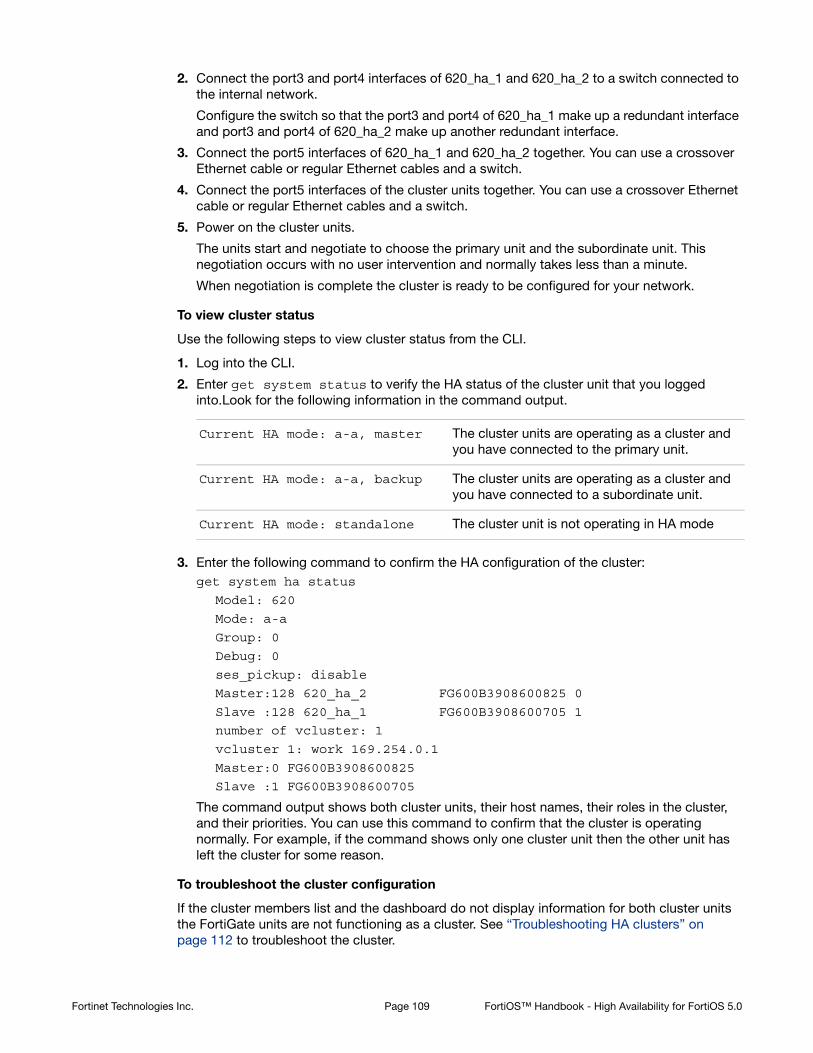
2. Connect the port3 and port4 interfaces of 620_ha_1 and 620_ha_2 to a switch connected to the internal network.
Configure the switch so that the port3 and port4 of 620_ha_1 make up a redundant interface and port3 and port4 of 620_ha_2 make up another redundant interface.
3. Connect the port5 interfaces of 620_ha_1 and 620_ha_2 together. You can use a crossover Ethernet cable or regular Ethernet cables and a switch.
4. Connect the port5 interfaces of the cluster units together. You can use a crossover Ethernet cable or regular Ethernet cables and a switch.
5. Power on the cluster units.
The units start and negotiate to choose the primary unit and the subordinate unit. This negotiation occurs with no user intervention and normally takes less than a minute.
When negotiation is complete the cluster is ready to be configured for your network.
To view cluster status
Use the following steps to view cluster status from the CLI.
1. Log into the CLI.
2. Enter get system status to verify the HA status of the cluster unit that you logged into.Look for the following information in the command output.
3. Enter the following command to confirm the HA configuration of the cluster:get system ha status
Model: 620
Mode: a-a
Group: 0
Debug: 0
ses_pickup: disable
Master:128 620_ha_2 FG600B3908600825 0
Slave :128 620_ha_1 FG600B3908600705 1
number of vcluster: 1
vcluster 1: work 169.254.0.1
Master:0 FG600B3908600825
Slave :1 FG600B3908600705
The command output shows both cluster units, their host names, their roles in the cluster, and their priorities. You can use this command to confirm that the cluster is operating normally. For example, if the command shows only one cluster unit then the other unit has left the cluster for some reason.
To troubleshoot the cluster configuration
If the cluster members list and the dashboard do not display information for both cluster units the FortiGate units are not functioning as a cluster. See “Troubleshooting HA clusters” on page 112 to troubleshoot the cluster.
Current HA mode: a-a, master The cluster units are operating as a cluster and you have connected to the primary unit.
Current HA mode: a-a, backup The cluster units are operating as a cluster and you have connected to a subordinate unit.
Current HA mode: standalone The cluster unit is not operating in HA mode
Fortinet Technologies Inc. Page 109 FortiOS™ Handbook - High Availability for FortiOS 5.0

To add basic configuration settings and the redundant interfaces
Use the following steps to add a few basic configuration settings and the redundant interfaces.
1. Add a password for the admin administrative account.config system admin
edit admin
set password <psswrd>
end
2. Temporarily delete the default route.
You cannot add an interface to a redundant interface if any settings (such as the default route) are configured for it. In this example the index of the default route is 1.config router static
delete 1
end
Fortinet Technologies Inc. Page 110 FortiOS™ Handbook - High Availability for FortiOS 5.0

3. Add the redundant interfaces:config system interface
edit Port1_Port2
set type redundant
set member port1 port2
set ip 172.20.120.141/24
set vdom root
next
edit Port3_Port4
set type redundant
set member port3 port4
set ip 10.11.101.100/24
set vdom root
end
The virtual MAC addresses of the FortiGate-620B interfaces change to the following. Note that port1 and port2 both have the port1 virtual MAC address and port3 and port4 both have the port3 virtual MAC address:
• port1 interface virtual MAC: 00-09-0f-09-00-00
• port10 interface virtual MAC: 00-09-0f-09-00-01
• port11 interface virtual MAC: 00-09-0f-09-00-02
• port12 interface virtual MAC: 00-09-0f-09-00-03
• port13 interface virtual MAC: 00-09-0f-09-00-04
• port14 interface virtual MAC: 00-09-0f-09-00-05
• port15 interface virtual MAC: 00-09-0f-09-00-06
• port16 interface virtual MAC: 00-09-0f-09-00-07
• port17 interface virtual MAC: 00-09-0f-09-00-08
• port18 interface virtual MAC: 00-09-0f-09-00-09
• port19 interface virtual MAC: 00-09-0f-09-00-0a
• port2 interface virtual MAC: 00-09-0f-09-00-00 (same as port1)
• port20 interface virtual MAC: 00-09-0f-09-00-0c
• port3 interface virtual MAC: 00-09-0f-09-00-0d
• port4 interface virtual MAC: 00-09-0f-09-00-0d (same as port3)
• port5 interface virtual MAC: 00-09-0f-09-00-0f
• port6 interface virtual MAC: 00-09-0f-09-00-10
• port7 interface virtual MAC: 00-09-0f-09-00-11
• port8 interface virtual MAC: 00-09-0f-09-00-12
• port9 interface virtual MAC: 00-09-0f-09-00-13
4. Add the default route.config router static
edit 1
set dst 0.0.0.0 0.0.0.0
set gateway 172.20.120.2
set device Port1_Port2
end
Fortinet Technologies Inc. Page 111 FortiOS™ Handbook - High Availability for FortiOS 5.0

To configure HA port monitoring for the redundant interfaces
1. Configure HA port monitoring for the redundant interfaces.config system ha
set monitor Port1_Port2 Port3_Port4
end
Troubleshooting HA clusters
This section describes some HA clustering troubleshooting techniques.
Ignoring hardware revisions
Some FortiGate platforms have gone through multiple hardware versions. In some cases the hardware changes between versions have meant that by default you cannot form a cluster if the FortiGate units in the cluster have different hardware versions. If you run into this problem you can use the following command on each FortiGate unit to cause the cluster to ignore different hardware versions:
execute ha ignore-hardware-revision {disable | enable | status}
This command is only available on FortiGate units that have had multiple hardware revisions. By default the command is set to prevent FortiOS from forming clusters between FortiGate units with different hardware revisions. You can enable this command to be able to create a cluster consisting of FortiGate units with different hardware revisions. Use the status option to verify the whether ignoring hardware revisions is enabled or disabled.
Affected hardware models include:
• FortiGate-100D
• FortiGate-300C
• FortiGate-80C and FortiWiFi-80C
• FortiGate-60C
Before you set up a cluster
Before you set up a cluster ask yourself the following questions about the FortiGate units that you are planning to use to create a cluster.
1. Do all the FortiGate units have the same hardware configuration? Including the same hard disk configuration and the same AMC cards installed in the same slots?
2. Do all FortiGate units have the same firmware build?
3. Are all FortiGate units set to the same operating mode (NAT or Transparent)?
4. Are all the FortiGate units operating in single VDOM mode?
5. If the FortiGate units are operating in multiple VDOM mode do they all have the same VDOM configuration?
In some cases you may be able to form a cluster if different FortiGate units have different firmware builds, different VDOM configurations, and are in different operating modes. However, if you encounter problems they may be resolved by installing the same firmware build on each unit, and give them the same VDOM configuration and operating mode.
Fortinet Technologies Inc. Page 112 FortiOS™ Handbook - High Availability for FortiOS 5.0
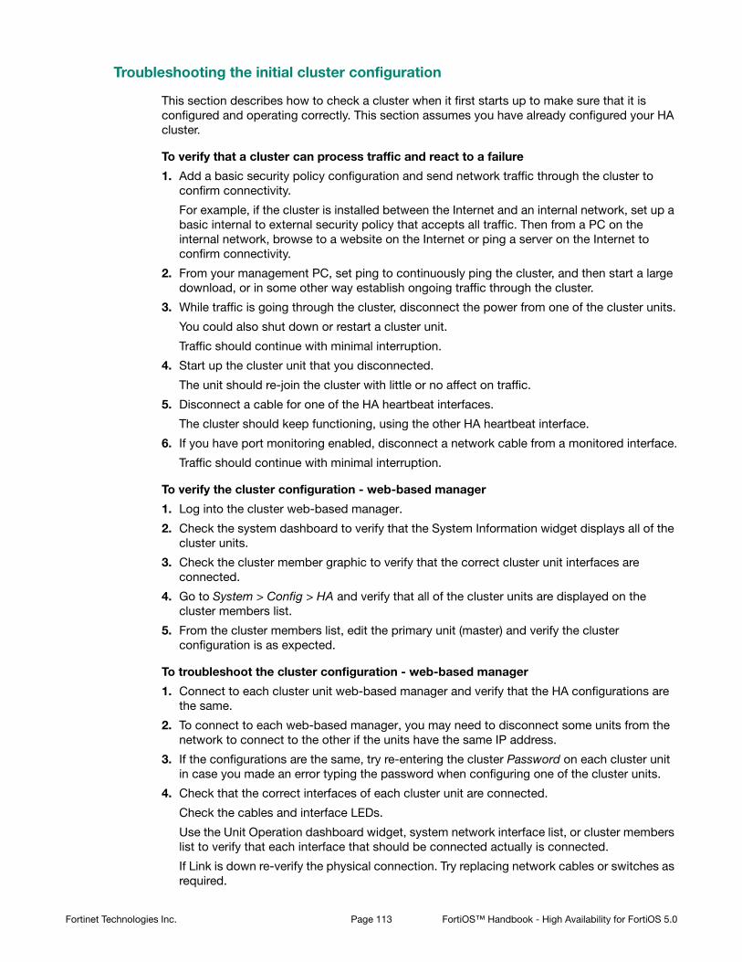
Troubleshooting the initial cluster configuration
This section describes how to check a cluster when it first starts up to make sure that it is configured and operating correctly. This section assumes you have already configured your HA cluster.
To verify that a cluster can process traffic and react to a failure
1. Add a basic security policy configuration and send network traffic through the cluster to confirm connectivity.
For example, if the cluster is installed between the Internet and an internal network, set up a basic internal to external security policy that accepts all traffic. Then from a PC on the internal network, browse to a website on the Internet or ping a server on the Internet to confirm connectivity.
2. From your management PC, set ping to continuously ping the cluster, and then start a large download, or in some other way establish ongoing traffic through the cluster.
3. While traffic is going through the cluster, disconnect the power from one of the cluster units.
You could also shut down or restart a cluster unit.
Traffic should continue with minimal interruption.
4. Start up the cluster unit that you disconnected.
The unit should re-join the cluster with little or no affect on traffic.
5. Disconnect a cable for one of the HA heartbeat interfaces.
The cluster should keep functioning, using the other HA heartbeat interface.
6. If you have port monitoring enabled, disconnect a network cable from a monitored interface.
Traffic should continue with minimal interruption.
To verify the cluster configuration - web-based manager
1. Log into the cluster web-based manager.
2. Check the system dashboard to verify that the System Information widget displays all of the cluster units.
3. Check the cluster member graphic to verify that the correct cluster unit interfaces are connected.
4. Go to System > Config > HA and verify that all of the cluster units are displayed on the cluster members list.
5. From the cluster members list, edit the primary unit (master) and verify the cluster configuration is as expected.
To troubleshoot the cluster configuration - web-based manager
1. Connect to each cluster unit web-based manager and verify that the HA configurations are the same.
2. To connect to each web-based manager, you may need to disconnect some units from the network to connect to the other if the units have the same IP address.
3. If the configurations are the same, try re-entering the cluster Password on each cluster unit in case you made an error typing the password when configuring one of the cluster units.
4. Check that the correct interfaces of each cluster unit are connected.
Check the cables and interface LEDs.
Use the Unit Operation dashboard widget, system network interface list, or cluster members list to verify that each interface that should be connected actually is connected.
If Link is down re-verify the physical connection. Try replacing network cables or switches as required.
Fortinet Technologies Inc. Page 113 FortiOS™ Handbook - High Availability for FortiOS 5.0

To verify the cluster configuration - CLI
1. Log into each cluster unit CLI.
You can use the console connection if you need to avoid the problem of units having the same IP address.
2. Enter the command get system status.
Look for the following information in the command output.
3. Verify that the get system ha status command displays all of the cluster units.
4. Enter the get system ha command to verify that the HA configuration is correct and the same for each cluster unit.
To troubleshoot the cluster configuration - CLI
1. Try using the following command to re-enter the cluster password on each cluster unit in case you made an error typing the password when configuring one of the cluster units.config system ha
set password <password>
end
2. Check that the correct interfaces of each cluster unit are connected.
Check the cables and interface LEDs.
Use get hardware nic <interface_name> command to confirm that each interface is connected. If the interface is connected the command output should contain a Link: up entry similar to the following:get hardware nic port1
.
.
.
Link: up
.
.
.
If Link is down, re-verify the physical connection. Try replacing network cables or switches as required.
Current HA mode: a-a, master The cluster units are operating as a cluster and you have connected to the primary unit.
Current HA mode: a-a, backup The cluster units are operating as a cluster and you have connected to a subordinate unit.
Current HA mode: standalone The cluster unit is not operating in HA mode
Fortinet Technologies Inc. Page 114 FortiOS™ Handbook - High Availability for FortiOS 5.0

More troubleshooting information
Much of the information in this HA guide can be useful for troubleshooting HA clusters. Here are some links to sections with more information.
• If sessions are lost after a failover you may need to change route-ttl to keep synchronized routes active longer. See “Change how long routes stay in a cluster unit routing table” on page 217.
• To control which cluster unit becomes the primary unit, you can change the device priority and enable override. See “Controlling primary unit selection using device priority and override” on page 40.
• Changes made to a cluster can be lost if override is enabled. See “Configuration changes can be lost if override is enabled” on page 41.
• In some cases, age differences among cluster units result in the wrong cluster unit becoming the primary unit. For example, if a cluster unit set to a high priority reboots, that unit will have a lower age than other cluster units. You can resolve this problem by resetting the age of one or more cluster units. See “Resetting the age of all cluster units” on page 35. You can also adjust how sensitive the cluster is to age differences. This can be useful if large age differences cause problems. See “Cluster age difference margin (grace period)” on page 33 and “Changing the cluster age difference margin” on page 33
• If one of the cluster units needs to be serviced or removed from the cluster for other reasons, you can do so without affecting the operation of the cluster. See “Disconnecting a cluster unit from a cluster” on page 185.
• The web-based manager and CLI will not allow you to configure HA if:
• You have configured a FortiGate interface to get its IP address using DHCP or PPPoE. See “FortiGate HA compatibility with PPPoE and DHCP” on page 42.
• You have enabled VRRP. See “VRRP” on page 265.
• You have enabled TCP session synchronization. See “FortiGate Session Life Support Protocol (FGSP)” on page 271.
• Some third-party network equipment may prevent HA heartbeat communication, resulting in a failure of the cluster or the creation of a split brain scenario. For example, some switches use packets with the same Ethertype as HA heartbeat packets use for internal functions and when used for HA heartbeat communication the switch generates CRC errors and the packets are not forwarded. See “Heartbeat packet Ethertypes” on page 197.
• Very busy clusters may not be able to send HA heartbeat packets quickly enough, also resulting in a split brain scenario. You may be able to resolve this problem by modifying HA heartbeat timing. See “Modifying heartbeat timing” on page 198.
• Very busy clusters may suffer performance reductions if session pickup is enabled. If possible you can disable this feature to improve performance. If you require session pickup for your cluster, several options are available for improving session pickup performance. See “Improving session synchronization performance” on page 232.
• If it takes longer than expected for a cluster to failover you can try changing how the primary unit sends gratuitous ARP packets. See “Changing how the primary unit sends gratuitous ARP packets after a failover” on page 201.
• You can also improve failover times by configuring the cluster for subsecond failover. See “Subsecond failover” on page 225 and “Failover performance” on page 241.
• When you first put a FortiGate unit in HA mode you may loose connectivity to the unit. This occurs because HA changes the MAC addresses of all FortiGate unit interfaces, including the one that you are connecting to. The cluster MAC addresses also change if you change the some HA settings such as the cluster group ID. The connection will be restored in a short time as your network and PC updates to the new MAC address. To reconnect sooner, you can update the ARP table of your management PC by deleting the ARP table entry for the
Fortinet Technologies Inc. Page 115 FortiOS™ Handbook - High Availability for FortiOS 5.0

FortiGate unit (or just deleting all arp table entries). You may be able to delete the arp table of your management PC from a command prompt using a command similar to arp -d.
• Since HA changes all cluster unit MAC addresses, if your network uses MAC address filtering you may have to make configuration changes to account for the HA MAC addresses.
• A network may experience packet loss when two FortiGate HA clusters have been deployed in the same broadcast domain. Deploying two HA clusters in the same broadcast domain can result in packet loss because of MAC address conflicts. The packet loss can be diagnosed by pinging from one cluster to the other or by pinging both of the clusters from a device within the broadcast domain. You can resolve the MAC address conflict by changing the HA Group ID configuration of the two clusters. The HA Group ID is sometimes also called the Cluster ID. See “Diagnosing packet loss with two FortiGate HA clusters in the same broadcast domain” on page 205.
• The cluster CLI displays slave is not in sync messages if there is a synchronization problem between the primary unit and one or more subordinate units. See “How to diagnose HA out of sync messages” on page 213.
• If you have configured dynamic routing and the new primary unit takes too long to update its routing table after a failover you can configure graceful restart and also optimize how routing updates are synchronized. See “Configuring graceful restart for dynamic routing failover” on page 215 and “Controlling how the FGCP synchronizes kernel routing table updates” on page 217.
• Some switches may not be able to detect that the primary unit has become a subordinate unit and will keep sending packets to the former primary unit. This can occur after a link failover if the switch does not detect the failure and does not clear its MAC forwarding table. See “Updating MAC forwarding tables when a link failover occurs” on page 223.
• If a link not directly connected to a cluster unit (for example, between a switch connected to a cluster interface and the network) fails you can enable remote link failover to maintain communication. See “Remote link failover” on page 226.
• If you find that some cluster units are not running the same firmware build you can reinstall the correct firmware build on the cluster to upgrade all cluster units to the same firmware build. See “Synchronizing the firmware build running on a new cluster unit” on page 175.
Fortinet Technologies Inc. Page 116 FortiOS™ Handbook - High Availability for FortiOS 5.0

Virtual clusters
This chapter provides an introduction to virtual clustering and also contains general procedures and configuration examples that describe how to configure FortiGate HA virtual clustering.
This chapter contains the following sections:
• Virtual clustering overview
• Configuring HA for virtual clustering
• Example: virtual clustering with two VDOMs and VDOM partitioning
• Example: inter-VDOM links in a virtual clustering configuration
• Troubleshooting virtual clustering
Virtual clustering overview
Virtual clustering is an extension of the FGCP for a cluster of 2 FortiGate units operating with multiple VDOMS enabled. Virtual clustering operates in active-passive mode to provide failover protection between two instances of a VDOM operating on two different cluster units. You can also operate virtual clustering in active-active mode to use HA load balancing to load balance sessions between cluster units. Alternatively, by distributing VDOM processing between the two cluster units you can also configure virtual clustering to provide load balancing by distributing sessions for different VDOMs to each cluster unit.
Figure shows an example virtual cluster configuration consisting of two FortiGate-620B units. The virtual cluster has two virtual domains, root and Eng_vdm.
The root virtual domain includes the port1 and port2 interfaces. The Eng_vdm virtual domain includes the port5 and port6 interfaces. The port3 and port4 interfaces (not shown in the diagram) are the HA heartbeat interfaces.
Virtual clustering and failover protection
Virtual clustering operates on a cluster of two (and only two) FortiGate units with VDOMs enabled. Each VDOM creates a cluster between instances of the VDOMs on the two FortiGate units in the virtual cluster. All traffic to and from the VDOM stays within the VDOM and is processed by the VDOM. One cluster unit is the primary unit for each VDOM and one cluster unit is the subordinate unit for each VDOM. The primary unit processes all traffic for the VDOM. The subordinate unit does not process traffic for the VDOM. If a cluster unit fails, all traffic fails over to the cluster unit that is still operating.
Virtual clustering and heartbeat interfaces
The HA heartbeat provides the same HA services in a virtual clustering configuration as in a standard HA configuration. One set of HA heartbeat interfaces provides HA heartbeat services for all of the VDOMs in the cluster. You do not have to add a heartbeat interface for each VDOM.
FortiGate virtual clustering is limited to a cluster of 2 FortiGate units with multiple VDOMs enabled. If you want to create a cluster of more than 2 FortiGate units operating with multiple VDOMS you could consider other solutions that either do not include multiple VDOMs in one cluster or employ a feature such as standalone session synchronization. See “FortiGate Session Life Support Protocol (FGSP)” on page 271.
Page 117

Figure 12:Example virtual cluster of two FortiGate-620B units
Virtual clustering and HA override
For a virtual cluster configuration, override is enabled by default for both virtual clusters when you:
• Enable VDOM partionning from the web-based manager by moving virtual domains to virtual cluster 2
• Enter set vcluster2 enable from the CLI config system ha command to enable virtual cluster 2.
Usually you would enable virtual cluster 2 and expect one cluster unit to be the primary unit for virtual cluster 1 and the other cluster unit to be the primary unit for virtual cluster 2. For this distribution to occur override must be enabled for both virtual clusters. Otherwise you will need to restart the cluster to force it to renegotiate.
For more information about HA override see “HA override” on page 38.
Virtual clustering and load balancing or VDOM partitioning
There are two ways to configure load balancing for virtual clustering. The first is to set the HA mode to active-active. The second is to configure VDOM partitioning. For virtual clustering, setting the HA Mode to active-active has the same result as active-active HA for a cluster without virtual domains. The primary unit receives all sessions and load balances them among the cluster units according to the load balancing schedule. All cluster units process traffic for all virtual domains.
In a VDOM partitioning virtual clustering configuration, the HA mode is set to active-passive. Even though virtual clustering operates in active-passive mode you can configure a form of load balancing by using VDOM partitioning to distribute traffic between both cluster units. To configure VDOM partitioning you set one cluster unit as the primary unit for some virtual
root TrafficEng_vdm Traffic
EngineeringNetwork
InternalNetwork Router
Port1
Port1
Port2
Port2
Switch
Switch
Switch
Switch
620_ha_1
620_ha_2
Port5
Port5
Port6
Port6
SSww
orPor
S2rt2
S
P
If override is enabled the cluster may renegotiate too often.You can choose to disable override at any time. If you decide to disable override, for best results, you should disable it for both cluster units.
Fortinet Technologies Inc. Page 118 FortiOS™ Handbook - High Availability for FortiOS 5.0

domains and you set the other cluster unit as the primary unit for other virtual domains. All traffic for a virtual domain is processed by the primary unit for that virtual domain. You can control the distribution of traffic between the cluster units by adjusting which cluster unit is the primary unit for each virtual domain.
For example, you could have 4 VDOMs, two of which have a high traffic volume and two of which have a low traffic volume. You can configure each cluster unit to be the primary unit for one of the high volume VDOMs and one of the low volume VDOMs. As a result each cluster unit will be processing traffic for a high volume VDOM and a low volume VDOM, resulting in an even distribution of traffic between the cluster units. You can adjust the distribution at any time. For example, if a low volume VDOM becomes a high volume VDOM you can move it from one cluster unit to another until the best balance is achieved.
From the web-based manager you configure VDOM partitioning by setting the HA mode to active-passive and distributing virtual domains between Virtual Cluster 1 and Virtual Cluster 2. You can also configure different device priorities, port monitoring, and remote link failover, for Virtual Cluster 1 and Virtual Cluster 2.
From the CLI you configure VDOM partitioning by setting the HA mode to a-p. Then you configure device priority, port monitoring, and remote link failover and specify the VDOMs to include in virtual cluster 1. You do the same for virtual cluster 2 by entering the config secondary-vcluster command.
Failover protection does not change. If one cluster unit fails, all sessions are processed by the remaining cluster unit. No traffic interruption occurs for the virtual domains for which the still functioning cluster unit was the primary unit. Traffic may be interrupted temporarily for virtual domains for which the failed unit was the primary unit while processing fails over to the still functioning cluster unit.
If the failed cluster unit restarts and rejoins the virtual cluster, VDOM partitioning load balancing is restored.
Configuring HA for virtual clustering
If your cluster uses VDOMs, you are configuring virtual clustering. Most virtual cluster HA options are the same as normal HA options. However, virtual clusters include VDOM partitioning options. Other differences between configuration options for regular HA and for virtual clustering HA are described below.
To configure HA options for a cluster with VDOMs enabled:
• Log into the global web-based manager and go to System > Config > HA.
• From the CLI, log into the Global Configuration:
The device priorities for virtual cluster 1 and virtual cluster 2 are not synchronized between the FortiGate units in the virtual cluster. You must configure these device priorities separately for each cluster unit.
Fortinet Technologies Inc. Page 119 FortiOS™ Handbook - High Availability for FortiOS 5.0

The following example shows how to configure active-active virtual clustering:
config global
config system ha
set mode a-a
set group-name vexample1.com
set password vHA_pass_1
end
end
The following example shows how to configure active-passive virtual clustering:
config global
config system ha
set mode a-p
set group-name vexample1.com
set password vHA_pass_1
end
end
The following example shows how to configure VDOM partitioning for virtual clustering. In the example, the FortiGate unit is configured with three VDOMs (domain_1, domain_2, and domain_3) in addition to the root VDOM. The example shows how to set up a basic HA configuration that sets the device priority of virtual cluster 1 to 200. The example also shows how to enable vcluster2, how to set the device priority of virtual cluster 2 to 100 and how to add the virtual domains domain_2 and domain_3 to virtual cluster 2.
When you enable multiple VDOMs, vcluster2 is enabled by default. Even so the command to enable vcluster2 is included in this example in case for some reason it has been disabled. When vcluster2 is enabled, override is also enabled.
The result of this configuration would be that the cluster unit that you are logged into becomes the primary unit for virtual cluster 1. This cluster unit processes all traffic for the root and domain_1 virtual domains.
config global
config system ha
set mode a-p
set group-name vexample1.com
set password vHA_pass_1
set priority 200
set vcluster2 enable
config secondary-vcluster
set vdom domain_2 domain_3
set priority 100
end
end
end
The following example shows how to use the execute ha manage command to change the device priorities for virtual cluster 1 and virtual cluster 2 for the other unit in the cluster. The commands set the device priority of virtual cluster 1 to 100 and virtual cluster 2 to 200.
Fortinet Technologies Inc. Page 120 FortiOS™ Handbook - High Availability for FortiOS 5.0

The result of this configuration would be that the other cluster unit becomes the primary unit for virtual cluster 2. This other cluster unit would process all traffic for the domain_2 and domain_3 virtual domains.
config global
execute ha manage 1
config system ha
set priority 100
set vcluster2 enable
config secondary-vcluster
set priority 200
end
end
end
end
Example: virtual clustering with two VDOMs and VDOM partitioning
This section describes how to configure the example virtual clustering configuration shown in Figure 13. This configuration includes two virtual domains, root and Eng_vdm and includes VDOM partitioning that sends all root VDOM traffic to 620_ha_1 and all Eng_vdom VDOM traffic to 620_ha_2. The traffic from the internal network and the engineering network is distributed between the two FortiGate units in the virtual cluster. If one of the cluster units fails, the remaining unit will process traffic for both VDOMs.
The procedures in this example describe some of many possible sequences of steps for configuring virtual clustering. For simplicity many of these procedures assume that you are starting with new FortiGate units set to the factory default configuration. However, this is not a requirement for a successful HA deployment. FortiGate HA is flexible enough to support a successful configuration from many different starting points.
Example virtual clustering network topology
Figure 13 shows a typical FortiGate-620B HA virtual cluster consisting of two FortiGate-620B units (620_ha_1 and 620_ha_2) connected to and internal network, an engineering network and the Internet. To simplify the diagram the heartbeat connections are not shown.
The traffic from the internal network is processed by the root VDOM, which includes the port1 and port2 interfaces. The traffic from the engineering network is processed by the Eng_vdm VDOM, which includes the port5 and port6 interfaces. VDOM partitioning is configured so that all traffic from the internal network is processed by 620_ha_1 and all traffic from the engineering network is processed by 620_ha_2.
This virtual cluster uses the default FortiGate-620B heartbeat interfaces (port3 and port4).
Fortinet Technologies Inc. Page 121 FortiOS™ Handbook - High Availability for FortiOS 5.0

Figure 13:Example virtual cluster of two FortiGate-620B units showing VDOM partitioning
General configuration steps
The section includes web-based manager and CLI procedures. These procedures assume that the FortiGate-620B units are running the same FortiOS firmware build and are set to the factory default configuration.
General configuration steps
1. Configure the FortiGate units for HA operation.
• Optionally change each unit’s host name.
• Configure HA.
2. Connect the cluster to the network.
3. Configure VDOM settings for the cluster:
• Enable multiple VDOMs.
• Add the Eng_vdm VDOM.
• Add port5 and port6 to the Eng_vdom.
4. Configure VDOM partitioning.
5. Confirm that the cluster units are operating as a virtual cluster and add basic configuration settings to the cluster.
• View cluster status from the web-based manager or CLI.
• Add a password for the admin administrative account.
• Change the IP addresses and netmasks of the port1, port2, port5, and port6 interfaces.
• Add a default routes to each VDOM.
EngineeringNetwork
10.12.101.0
InternalNetwork
10.11.101.0
Port1: 172.20.120.141Port2: 10.11.101.100Port5: 172.20.120.143Port6: 10.12.101.100
Router
172.20.120.2
620_ha_1
620_ha_2
Port5
Port5
Port6
Port6
orPor
P
root TrafficEng_vdm Traffic
Port1
Port1
Port2
Port2
Fortinet Technologies Inc. Page 122 FortiOS™ Handbook - High Availability for FortiOS 5.0

Configuring virtual clustering with two VDOMs and VDOM partitioning - web-based manager
These procedures assume you are starting with two FortiGate-620B units with factory default settings.
To configure the FortiGate-620B units for HA operation
1. Power on the first FortiGate-620B unit and log into the web-based manager.
2. On the System Information dashboard widget, beside Host Name select Change.
3. Enter a new Host Name for this FortiGate unit.
4. Select OK.
5. Go to System > Config > HA and change the following settings.
6. Select OK.
The FortiGate unit negotiates to establish an HA cluster. When you select OK you may temporarily lose connectivity with the FortiGate unit as the HA cluster negotiates and the FGCP changes the MAC address of the FortiGate unit interfaces (see “Cluster virtual MAC
New Name 620_ha_1
Mode Active-Passive
Group Name vexample2.com
Password vHA_pass_2
Fortinet Technologies Inc. Page 123 FortiOS™ Handbook - High Availability for FortiOS 5.0

addresses” on page 200). The MAC addresses of the FortiGate-620B interfaces change to the following virtual MAC addresses:
• port1 interface virtual MAC: 00-09-0f-09-00-00
• port10 interface virtual MAC: 00-09-0f-09-00-01
• port11 interface virtual MAC: 00-09-0f-09-00-02
• port12 interface virtual MAC: 00-09-0f-09-00-03
• port13 interface virtual MAC: 00-09-0f-09-00-04
• port14 interface virtual MAC: 00-09-0f-09-00-05
• port15 interface virtual MAC: 00-09-0f-09-00-06
• port16 interface virtual MAC: 00-09-0f-09-00-07
• port17 interface virtual MAC: 00-09-0f-09-00-08
• port18 interface virtual MAC: 00-09-0f-09-00-09
• port19 interface virtual MAC: 00-09-0f-09-00-0a
• port2 interface virtual MAC: 00-09-0f-09-00-0b
• port20 interface virtual MAC: 00-09-0f-09-00-0c
• port3 interface virtual MAC: 00-09-0f-09-00-0d
• port4 interface virtual MAC: 00-09-0f-09-00-0e
• port5 interface virtual MAC: 00-09-0f-09-00-0f
• port6 interface virtual MAC: 00-09-0f-09-00-10
• port7 interface virtual MAC: 00-09-0f-09-00-11
• port8 interface virtual MAC: 00-09-0f-09-00-12
• port9 interface virtual MAC: 00-09-0f-09-00-13
To be able to reconnect sooner, you can update the ARP table of your management PC by deleting the ARP table entry for the FortiGate unit (or just deleting all arp table entries). You may be able to delete the arp table of your management PC from a command prompt using a command similar to arp -d.
You can use the get hardware nic (or diagnose hardware deviceinfo nic) CLI command to view the virtual MAC address of any FortiGate unit interface. For example, use the following command to view the port1 interface virtual MAC address (Current_HWaddr) and the port1 permanent MAC address (Permanent_HWaddr):get hardware nic port1
.
.
.
MAC: 00:09:0f:09:00:00
Permanent_HWaddr: 02:09:0f:78:18:c9
.
.
.
7. Power off the first FortiGate unit.
8. Repeat these steps for the second FortiGate unit.
Set the second FortiGate unit host name to:
New Name 620_ha_2
Fortinet Technologies Inc. Page 124 FortiOS™ Handbook - High Availability for FortiOS 5.0

To connect the cluster to the network
1. Connect the port1 interfaces of 620_ha_1 and 620_ha_2 to a switch connected to the Internet.
2. Connect the port5 interfaces of 620_ha_1 and 620_ha_2 to switch connected to the Internet.
You could use the same switch for the port1 and port5 interfaces.
3. Connect the port2 interfaces of 620_ha_1 and 620_ha_2 to a switch connected to the internal network.
4. Connect the port6 interfaces of 620_ha_1 and 620_ha_2 to a switch connected to the engineering network.
5. Connect the port3 interfaces of the cluster units together. You can use a crossover Ethernet cable or regular Ethernet cables and a switch.
6. Connect the port4 interfaces of the cluster units together. You can use a crossover Ethernet cable or regular Ethernet cables and a switch.
7. Power on the cluster units.
The units start and negotiate to choose the primary unit and the subordinate unit. This negotiation occurs with no user intervention.
When negotiation is complete you can continue.
To configure VDOM settings for the cluster
1. Log into the web-based manager.
2. On the System Information dashboard widget, beside Virtual Domain select Enable.
3. Select OK and then log back into the web-based manager.
4. Go to System > VDOM and select Create New to add a new VDOM.
5. Go to System > Network > Interfaces.
6. Edit the port5 interface, add it to the Eng_vdm VDOM and configure other interface settings:
7. Select OK.
8. Edit the port6 interface, add it to the Eng_vdm VDOM and configure other interface settings:
9. Select OK.
To add a default route to each VDOM
1. Go to System > VDOM and Enter the root VDOM.
Name Eng_vdm
Alias Engineering_external
Virtual Domain Eng_vdm
IP/Netmask 172.20.120.143/24
Alias Engineering_internal
Virtual Domain Eng_vdm
IP/Netmask 10.120.101.100/24
Administrative Access
HTTPS, PING, SSH
Fortinet Technologies Inc. Page 125 FortiOS™ Handbook - High Availability for FortiOS 5.0

2. Go to Router > Static > Static Routes.
3. Change the default route.
4. Select Global.
5. Go to System > VDOM and Enter the Eng_vdm VDOM.
6. Go to Router > Static > Static Routes.
7. Change the default route.
To configure VDOM partitioning
1. Go to System > Config > HA.
The cluster members shows two cluster units in Virtual Cluster 1.
2. Edit the cluster unit with the Role of MASTER.
3. Change VDOM partitioning to move the Eng_vdm to the Virtual Cluster 2 list.
4. Select OK.
5. Change the Virtual Cluster 1 and Virtual Cluster 2 device priorities for each cluster unit to the following:
You can do this by editing the HA configurations of each cluster unit in the cluster members list and changing device priorities.
Since the device priority of Virtual Cluster 1 is highest for 620_ha_1 and since the root VDOM is in Virtual Cluster 1, all traffic for the root VDOM is processed by 620_ha_1.
Since the device priority of Virtual Cluster 2 is highest for 620_ha_2 and since the Eng_vdm VDOM is in Virtual Cluster 2, all traffic for the Eng_vdm VDOM is processed by 620_ha_2.
To view cluster status and verify the VDOM partitioning configuration
1. Log into the web-based manager.
Destination IP/Mask 0.0.0.0/0.0.0.0
Gateway 172.20.120.2
Device port1
Distance 10
Destination IP/Mask 0.0.0.0/0.0.0.0
Gateway 172.20.120.2
Device port5
Distance 10
Device Priority
Host Name Virtual Cluster 1 Virtual Cluster 2
620_ha_1 200 100
620_ha_2 100 200
Fortinet Technologies Inc. Page 126 FortiOS™ Handbook - High Availability for FortiOS 5.0
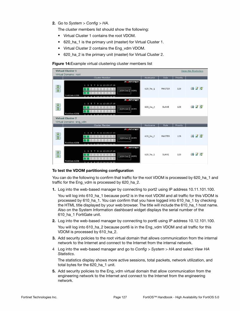
2. Go to System > Config > HA.
The cluster members list should show the following:
• Virtual Cluster 1 contains the root VDOM.
• 620_ha_1 is the primary unit (master) for Virtual Cluster 1.
• Virtual Cluster 2 contains the Eng_vdm VDOM.
• 620_ha_2 is the primary unit (master) for Virtual Cluster 2.
Figure 14:Example virtual clustering cluster members list
To test the VDOM partitioning configuration
You can do the following to confirm that traffic for the root VDOM is processed by 620_ha_1 and traffic for the Eng_vdm is processed by 620_ha_2.
1. Log into the web-based manager by connecting to port2 using IP address 10.11.101.100.
You will log into 610_ha_1 because port2 is in the root VDOM and all traffic for this VDOM is processed by 610_ha_1. You can confirm that you have logged into 610_ha_1 by checking the HTML title displayed by your web browser. The title will include the 610_ha_1 host name. Also on the System Information dashboard widget displays the serial number of the 610_ha_1 FortiGate unit.
2. Log into the web-based manager by connecting to port6 using IP address 10.12.101.100.
You will log into 610_ha_2 because port6 is in the Eng_vdm VDOM and all traffic for this VDOM is processed by 610_ha_2.
3. Add security policies to the root virtual domain that allows communication from the internal network to the Internet and connect to the Internet from the internal network.
4 Log into the web-based manager and go to Config > System > HA and select View HA Statistics.
The statistics display shows more active sessions, total packets, network utilization, and total bytes for the 620_ha_1 unit.
5. Add security policies to the Eng_vdm virtual domain that allow communication from the engineering network to the Internet and connect to the Internet from the engineering network.
Fortinet Technologies Inc. Page 127 FortiOS™ Handbook - High Availability for FortiOS 5.0
6. Log into the web-based manager and go to Config > System > HA and select View HA Statistics.
The statistics display shows more active sessions, total packets, network utilization, and total bytes for the 620_ha_2 unit.
Configuring virtual clustering with two VDOMs and VDOM partitioning - CLI
These procedures assume you are starting with two FortiGate-620B units with factory default settings.
To configure the FortiGate-620B units for HA operation
1. Power on the first FortiGate-620B unit and log into the CLI.
2. Change the host name for this FortiGate unit:config system global
set hostname 620_ha_1
end
3. Configure HA settings.config system ha
set mode a-p
set group-name vexample2.com
set password vHA_pass_2
end
The FortiGate unit negotiates to establish an HA cluster. You may temporarily lose connectivity with the FortiGate unit as the HA cluster negotiates and the FGCP changes the MAC address of the FortiGate unit interfaces (see “Cluster virtual MAC addresses” on
Fortinet Technologies Inc. Page 128 FortiOS™ Handbook - High Availability for FortiOS 5.0

page 200). The MAC addresses of the FortiGate-620B interfaces change to the following virtual MAC addresses:
• port1 interface virtual MAC: 00-09-0f-09-00-00
• port10 interface virtual MAC: 00-09-0f-09-00-01
• port11 interface virtual MAC: 00-09-0f-09-00-02
• port12 interface virtual MAC: 00-09-0f-09-00-03
• port13 interface virtual MAC: 00-09-0f-09-00-04
• port14 interface virtual MAC: 00-09-0f-09-00-05
• port15 interface virtual MAC: 00-09-0f-09-00-06
• port16 interface virtual MAC: 00-09-0f-09-00-07
• port17 interface virtual MAC: 00-09-0f-09-00-08
• port18 interface virtual MAC: 00-09-0f-09-00-09
• port19 interface virtual MAC: 00-09-0f-09-00-0a
• port2 interface virtual MAC: 00-09-0f-09-00-0b
• port20 interface virtual MAC: 00-09-0f-09-00-0c
• port3 interface virtual MAC: 00-09-0f-09-00-0d
• port4 interface virtual MAC: 00-09-0f-09-00-0e
• port5 interface virtual MAC: 00-09-0f-09-00-0f
• port6 interface virtual MAC: 00-09-0f-09-00-10
• port7 interface virtual MAC: 00-09-0f-09-00-11
• port8 interface virtual MAC: 00-09-0f-09-00-12
• port9 interface virtual MAC: 00-09-0f-09-00-13
To be able to reconnect sooner, you can update the ARP table of your management PC by deleting the ARP table entry for the FortiGate unit (or just deleting all arp table entries). You may be able to delete the arp table of your management PC from a command prompt using a command similar to arp -d.
You can use the get hardware nic (or diagnose hardware deviceinfo nic) CLI command to view the virtual MAC address of any FortiGate unit interface. For example, use the following command to view the port1 interface virtual MAC address (Current_HWaddr) and the port1 permanent MAC address (Permanent_HWaddr):get hardware nic port1
.
.
.
MAC: 00:09:0f:09:00:00
Permanent_HWaddr: 02:09:0f:78:18:c9
.
.
.
Fortinet Technologies Inc. Page 129 FortiOS™ Handbook - High Availability for FortiOS 5.0

4. Display the HA configuration (optional).get system ha
group-id : 0
group-name : vexample2.com
mode : a-p
password : *
hbdev : "port3" 50 "port4" 50
session-sync-dev :
route-ttl : 10
route-wait : 0
route-hold : 10
sync-config : enable
encryption : disable
authentication : disable
hb-interval : 2
hb-lost-threshold : 20
helo-holddown : 20
arps : 5
arps-interval : 8
session-pickup : disable
link-failed-signal : disable
uninterruptible-upgrade: enable
ha-mgmt-status : disable
ha-eth-type : 8890
hc-eth-type : 8891
l2ep-eth-type : 8893
subsecond : disable
vcluster2 : disable
vcluster-id : 1
override : disable
priority : 128
monitor :
pingserver-monitor-interface:
pingserver-failover-threshold: 0
pingserver-flip-timeout: 60
vdom : "root"
5. Power off the first FortiGate unit.
6. Repeat these steps for the second FortiGate unit.
Set the other FortiGate unit host name to:config system global
set hostname 620_ha_2
end
To connect the cluster to the network
1. Connect the port1 interfaces of 620_ha_1 and 620_ha_2 to a switch connected to the Internet.
2. Connect the port5 interfaces of 620_ha_1 and 620_ha_2 to switch connected to the Internet.
You could use the same switch for port1 and port5.
Fortinet Technologies Inc. Page 130 FortiOS™ Handbook - High Availability for FortiOS 5.0

3. Connect the port2 interfaces of 620_ha_1 and 620_ha_2 to a switch connected to the internal network.
4. Connect the port6 interfaces of 620_ha_1 and 620_ha_2 to a switch connected to the engineering network.
5. Connect the port3 interfaces of the cluster units together. You can use a crossover Ethernet cable or regular Ethernet cables and a switch.
6. Connect the port4 interfaces of the cluster units together. You can use a crossover Ethernet cable or regular Ethernet cables and a switch.
7. Power on the cluster units.
The units start and negotiate to choose the primary unit and the subordinate unit. This negotiation occurs with no user intervention.
When negotiation is complete you can continue.
To configure VDOM settings for the cluster
1. Log into the CLI.
2. Enter the following command to enable multiple VDOMs for the cluster.config system global
set vdom-admin enable
end
3. Log back into the CLI.
4. Enter the following command to add the Eng_vdm VDOM:config vdom
edit Eng_vdm
end
5. Edit the port5 interface, add it to the Eng_vdm VDOM and configure other interface settings:config global
config system interface
edit port5
set vdom Eng_vdm
set alias Engineering_external
set ip 172.20.12.143/24
next
edit port6
set vdom Eng_vdm
set alias Engineering_internal
set ip 10.120.101.100/24
end
end
Fortinet Technologies Inc. Page 131 FortiOS™ Handbook - High Availability for FortiOS 5.0

To add a default route to each VDOM
1. Enter the following command to add default routes to the root and Eng_vdm VDOMs.config vdom
edit root
config router static
edit 1
set dst 0.0.0.0/0.0.0.0
set gateway 172.20.120.2
set device port1
end
next
edit Eng_vdm
config router static
edit 1
set dst 0.0.0.0/0.0.0.0
set gateway 172.20.120.2
set device port5
end
end
To configure VDOM partitioning
1. Enter the get system ha status command to view cluster unit status:
For example, from the 620_ha_2 cluster unit CLI:config global
get system ha status
Model: 620
Mode: a-p
Group: 0
Debug: 0
ses_pickup: disable
Master:128 620_ha_2 FG600B3908600825 0
Slave :128 620_ha_1 FG600B3908600705 1
number of vcluster: 1
vcluster 1: work 169.254.0.1
Master:0 FG600B3908600825
Slave :1 FG600B3908600705
This command output shows that VDOM partitioning has not been configured because only virtual cluster 1 is shown. The command output also shows that the 620_ha_2 is the primary unit for the cluster and for virtual cluster 1 because this cluster unit has the highest serial number
2. Enter the following commands to configure VDOM partitioning:config global
config system ha
set vcluster2 enable
config secondary-vcluster
set vdom Eng_vdm
end
end
end
Fortinet Technologies Inc. Page 132 FortiOS™ Handbook - High Availability for FortiOS 5.0

3. Enter the get system ha status command to view cluster unit status:
For example, from the 620_ha_2 cluster unit CLI:config global
get system ha status
Model: 620
Mode: a-p
Group: 0
Debug: 0
ses_pickup: disable
Master:128 620_ha_2 FG600B3908600825 0
Slave :128 620_ha_1 FG600B3908600705 1
number of vcluster: 2
vcluster 1: work 169.254.0.1
Master:0 FG600B3908600825
Slave :1 FG600B3908600705
vcluster 2: work 169.254.0.1
Master:0 FG600B3908600825
Slave :1 FG600B3908600705
This command output shows VDOM partitioning has been configured because both virtual cluster 1 and virtual cluster 2 are visible. However the configuration is not complete because 620_ha_2 is the primary unit for both virtual clusters. The command output shows this because under both vcluster entries the Master entry shows FG600B3908600825, which is the serial number of 620_ha_2. As a result of this configuration, 620_ha_2 processes traffic for both VDOMs and 620_ha_1 does not process any traffic.
4. Change the Virtual Cluster 1 and Virtual Cluster 2 device priorities for each cluster unit so that 620_ha_1 processes virtual cluster 1 traffic and 620_ha_2 processes virtual cluster 2 traffic.
Since the root VDOM is in virtual cluster 1 and the Eng_vdm VDOM is in virtual cluster 2 the result of this configuration will be that 620_ha_1 will process all root VDOM traffic and
Fortinet Technologies Inc. Page 133 FortiOS™ Handbook - High Availability for FortiOS 5.0

620_ha_2 will process all Eng_vdm traffic. You make this happen by changing the cluster unit device priorities for each virtual cluster. You could use the following settings:
Since the device priority is not synchronized you can edit the device priorities of each virtual cluster on each FortiGate unit separately. To do this:
• Log into the CLI and note the FortiGate unit you have actually logged into (for example, by checking the host name displayed in the CLI prompt).
• Change the virtual cluster 1 and 2 device priorities for this cluster unit.
• Then use the execute ha manage command to log into the other cluster unit CLI and set its virtual cluster 1 and 2 device priorities.
Enter the following commands from the 620_ha_1 cluster unit CLI:config global
config system ha
set priority 200
config secondary-vcluster
set priority 100
end
end
end
Enter the following commands from the 620_ha_2 cluster unit CLI:config global
config system ha
set priority 100
config secondary-vcluster
set priority 200
end
end
end
Since the device priority of Virtual Cluster 1 is highest for 620_ha_1 and since the root VDOM is in Virtual Cluster 1, all traffic for the root VDOM is processed by 620_ha_1.
Since the device priority of Virtual Cluster 2 is highest for 620_ha_2 and since the Eng_vdm VDOM is in Virtual Cluster 2, all traffic for the Eng_vdm VDOM is processed by 620_ha_2.
Device Priority
Host Name Virtual Cluster 1 Virtual Cluster 2
620_ha_1 200 100
620_ha_2 100 200
The cluster may renegotiate during this step resulting in a temporary loss of connection to the CLI and a temporary service interruption.
Fortinet Technologies Inc. Page 134 FortiOS™ Handbook - High Availability for FortiOS 5.0
To verify the VDOM partitioning configuration
1. Log into the 620_ha_2 cluster unit CLI and enter the following command:config global
get system ha status
Model: 620
Mode: a-p
Group: 0
Debug: 0
ses_pickup: disable
Slave :100 620_ha_2 FG600B3908600825 0
Master:200 620_ha_1 FG600B3908600705 1
number of vcluster: 2
vcluster 1: standby 169.254.0.2
Slave :1 FG600B3908600825
Master:0 FG600B3908600705
vcluster 2: work 169.254.0.1
Master:0 FG600B3908600825
Slave :1 FG600B3908600705
The command output shows that 620_ha_1 is the primary unit for virtual cluster 1 (because the command output show the Master of virtual cluster 1 is the serial number of 620_ha_1) and that 620_ha_2 is the primary unit for virtual cluster 2.
If you enter the same command from the 620_ha_1 CLI the same information is displayed but in a different order. The command always displays the status of the cluster unit that you are logged into first.config global
get system ha status
Model: 620
Mode: a-p
Group: 0
Debug: 0
ses_pickup: disable
Master:200 620_ha_1 FG600B3908600705 1
Slave :100 620_ha_2 FG600B3908600825 0
number of vcluster: 2
vcluster 1: work 169.254.0.2
Master:0 FG600B3908600705
Slave :1 FG600B3908600825
vcluster 2: standby 169.254.0.1
Slave :1 FG600B3908600705
Master:0 FG600B3908600825
To test the VDOM partitioning configuration
You can do the following to confirm that traffic for the root VDOM is processed by 620_ha_1 and traffic for the Eng_vdm is processed by 620_ha_2. These steps assume the cluster is operating correctly.
1. Log into the CLI by connecting to port2 using IP address 10.11.101.100.
You will log into 610_ha_1 because port2 is in the root VDOM and all traffic for this VDOM is processed by 610_ha_1. You can confirm that you have logged into 610_ha_1 by checking
Fortinet Technologies Inc. Page 135 FortiOS™ Handbook - High Availability for FortiOS 5.0

the host name in the CLI prompt. Also the get system status command displays the status of the 610_ha_1 cluster unit.
2. Log into the web-based manager or CLI by connecting to port6 using IP address 10.12.101.100.
You will log into 610_ha_2 because port6 is in the Eng_vdm VDOM and all traffic for this VDOM is processed by 610_ha_2.
3. Add security policies to the root virtual domain that allow communication from the internal network to the Internet and connect to the Internet from the internal network.
4. Log into the web-based manager and go to Config > System > HA and select View HA Statistics.
The statistics display shows more active sessions, total packets, network utilization, and total bytes for the 620_ha_1 unit.
5. Add security policies to the Eng_vdm virtual domain that allow communication from the engineering network to the Internet and connect to the Internet from the engineering network.
6. Log into the web-based manager and go to Config > System > HA and select View HA Statistics.
The statistics display shows more active sessions, total packets, network utilization, and total bytes for the 620_ha_2 unit.
Example: inter-VDOM links in a virtual clustering configuration
In a virtual domain configuration you can use inter-VDOM links to route traffic between two virtual domains operating in a single FortiGate unit without using physical interfaces. Adding an inter-VDOM link has the affect of adding two interfaces to the FortiGate unit and routing traffic between the virtual domains using the inter-VDOM link interfaces.
In a virtual clustering configuration inter-VDOM links can only be made between virtual domains that are in the same virtual cluster. So, if you are planning on configuring inter-VDOM links in a virtual clustering configuration, you should make sure the virtual domains that you want to link are in the same virtual cluster.
For example, the following tables show an example virtual clustering configuration where each virtual cluster contains three virtual domains. In this configuration you can configure inter-VDOM links between root and vdom_1 and between vdom_2 and vdom_3. But, you cannot configure inter-VDOM links between root and vdom_2 or between vdom_1 and vdom_3 (and so on).
Virtual Domains Hostname
FortiGate_A FortiGate_B
root
vdom_1
Priority
200
Priority
100
Role
Primary
Role
Subordinate
Fortinet Technologies Inc. Page 136 FortiOS™ Handbook - High Availability for FortiOS 5.0

Configuring inter-VDOM links in a virtual clustering configuration
Configuring inter-VDOM links in a virtual clustering configuration is very similar to configuring inter-VDOM links for a standalone FortiGate unit. The main difference the config system vdom-link command includes the vcluster keyword. The default setting for vcluster is vcluster1. So you only have to use the vcluster keyword if you are added an inter-VDOM link to virtual cluster 2.
To add an inter-VDOM link to virtual cluster 1
This procedure describes how to create an inter-VDOM link to virtual cluster 1 that results in a link between the root and vdom_1 virtual domains.
1 Add an inter-VDOM link called vc1link.config global
config system vdom-link
edit vc1link
end
Adding the inter-VDOM link also adds two interfaces. In this example, these interfaces are called vc1link0 and vc1link1. These interfaces appear in all CLI and web-based manager interface lists. These interfaces can only be added to virtual domains in virtual cluster 1.
2. Bind the vc1link0 interface to the root virtual domain and bind the vc1link1 interface to the vdom_1 virtual domain.config system interface
edit vc1link0
set vdom root
next
edit vc1link1
set vdom vdom_1
end
To add an inter-VDOM link to virtual cluster 2
This procedure describes how to create an inter-VDOM link to virtual cluster 2 that results in a link between the vdom_2 and vdom_3 virtual domains.
Virtual Domains Hostname
FortiGate_A FortiGate_B
vdom_2
vdom_3
Priority
100
Priority
200
Role
Subordinate
Role
Primary
Inter-VDOM links are also called internal point-to-point interfaces.
Fortinet Technologies Inc. Page 137 FortiOS™ Handbook - High Availability for FortiOS 5.0

1 Add an inter-VDOM link called vc2link.config global
config system vdom-link
edit vc2link
set vcluster vcluster2
end
Adding the inter-VDOM link also adds two interfaces. In this example, these interfaces are called vc2link0 and vc2link1. These interfaces appear in all CLI and web-based manager interface lists. These interfaces can only be added to virtual domains in virtual cluster 2.
2. Bind the vc2link0 interface to the vdom_2 virtual domain and bind the vc2link1 interface to the vdom_3 virtual domain.config system interface
edit vc2link0
set vdom vdom_2
next
edit vc2link1
set vdom vdom_3
end
Troubleshooting virtual clustering
Troubleshooting virtual clusters is similar to troubleshooting any cluster (see “Troubleshooting HA clusters” on page 112). This section describes a few testing and troubleshooting techniques for virtual clustering.
To test the VDOM partitioning configuration
You can do the following to confirm that traffic for different VDOMs will be distributed among both FortiGate units in the virtual cluster. These steps assume the cluster is otherwise operating correctly.
1. Log into the web-based manager or CLI using the IP addresses of interfaces in each VDOM.
Confirm that you have logged into the FortiGate unit that should be processing traffic for that VDOM by checking the HTML title displayed by your web browser or the CLI prompt. Both of these should include the host name of the cluster unit that you have logged into. Also on the system Dashboard, the System Information widget displays the serial number of the FortiGate unit that you logged into. From the CLI the get system status command displays the status of the cluster unit that you logged into.
2. To verify that the correct cluster unit is processing traffic for a VDOM:
• Add security policies to the VDOM that allow communication between the interfaces in the VDOM.
• Optionally enable traffic logging and other monitoring for that VDOM and these security policies.
• Start communication sessions that pass traffic through the VDOM.
• Log into the web-based manager and go to Config > System > HA and select View HA Statistics. Verify that the statistics display shows more active sessions, total packets, network utilization, and total bytes for the unit that should be processing all traffic for the VDOM.
• Optionally check traffic logging and the Top Sessions Widget for the FortiGate unit that should be processing traffic for that VDOM to verify that the traffic is being processed by this FortiGate unit.
Fortinet Technologies Inc. Page 138 FortiOS™ Handbook - High Availability for FortiOS 5.0

Full mesh HA
This chapter provides an introduction to full mesh HA and also contains general procedures and configuration examples that describe how to configure FortiGate full mesh HA.
The examples in this chapter include example values only. In most cases you will substitute your own values. The examples in this chapter also do not contain detailed descriptions of configuration parameters.
This chapter contains the following sections:
• Full mesh HA overview
• Example: full mesh HA configuration
• Troubleshooting full mesh HA
Full mesh HA overview
When two or more FortiGate units are connected to a network in an HA cluster the reliability of the network is improved because the HA cluster replaces a single FortiGate unit as a single point of failure. With a cluster, a single FortiGate unit is replaced by a cluster of two or more FortiGate units.
However, even with a cluster, potential single points of failure remain. The interfaces of each cluster unit connect to a single switch and that switch provides a single connection to the network. If the switch fails or if the connection between the switch and the network fails service is interrupted to that network.
The HA cluster does improve the reliability of the network because switches are not as complex components as FortiGate units, so are less likely to fail. However, for even greater reliability, a configuration is required that includes redundant connections between the cluster the networks that it is connected to.
FortiGate models that support 802.3ad Aggregate or Redundant interfaces can be used to create a cluster configuration called full mesh HA. Full mesh HA is a method of reducing the number of single points of failure on a network that includes an HA cluster.
This redundant configuration can be achieved using FortiGate 802.3ad Aggregate or Redundant interfaces and a full mesh HA configuration. In a full mesh HA configuration, you connect an HA cluster consisting of two or more FortiGate units to the network using 802.3ad Aggregate or Redundant interfaces and redundant switches. Each 802.3ad Aggregate or Redundant interface is connected to two switches and both of these switches are connected to the network.
The resulting full mesh configuration, an example is shown in Figure 15, includes redundant connections between all network components. If any single component or any single connection fails, traffic automatically switches to the redundant component and connection and traffic flow resumes.
Page 139

Figure 15:SIngle points of failure in a standalone and HA network configuration
Full mesh HA and redundant heartbeat interfaces
A full mesh HA configuration also includes redundant HA heartbeat interfaces. At least two heartbeat interfaces should be selected in the HA configuration and both sets of HA heartbeat interfaces should be connected. The HA heartbeat interfaces do not have to be configured as redundant interfaces because the FGCP handles failover between heartbeat interfaces.
Full mesh HA, redundant interfaces and 802.3ad aggregate interfaces
Full mesh HA is supported for both redundant interfaces and 802.3ad aggregate interfaces. In most cases you would simply use redundant interfaces. However, if your switches support 802.3ad aggregate interfaces and split multi-trunking you can use aggregate interfaces in place of redundant interfaces for full mesh HA. One advantage of using aggregate interfaces is that all
Standalone FortiGate unitsingle points of failure
Router
FortiGate clustersingle points of failure
InternalNetwork
10.11.101.0
Router
Switch
Switch
620_ha_1
620_ha_2
Port1
Port1
Port2
Port2
Port3
Port3
Port4
Port4
Sw
S
Fortinet Technologies Inc. Page 140 FortiOS™ Handbook - High Availability for FortiOS 5.0

of the physical interfaces in the aggregate interface can send and receive packets. As a result, using aggregate interfaces may increase the bandwidth capacity of the cluster.
Usually redundant and aggregate interfaces consist of two physical interfaces. However, you can add more than two physical interfaces to a redundant or aggregate interface. Adding more interfaces can increase redundancy protection. Adding more interfaces can also increase bandwidth capacity if you are using 802.3ad aggregate interfaces.
Example: full mesh HA configuration
Figure 15 shows a full mesh HA configuration with a cluster of two FortiGate-620b units. This section describes the FortiGate configuration settings and network components required for a full mesh HA configuration. This section also contains example steps for setting up this full mesh HA configuration. The procedures in this section describe one of many possible sequences of steps for configuring full mesh HA. As you become more experienced with FortiOS, HA, and full mesh HA you may choose to use a different sequence of configuration steps.
Figure 16:Full Mesh HA configuration
For simplicity these procedures assume that you are starting with two new FortiGate units set to the factory default configuration. However, starting from the default configuration is not a requirement for a successful HA deployment. FortiGate HA is flexible enough to support a successful configuration from many different starting points.
These procedures describe how to configure a cluster operating in NAT/Route mode because NAT/Route is the default FortiGate operating mode. However, the steps are the same if the cluster operates in Transparent mode. You can either switch the cluster units to operate in Transparent mode before beginning these procedures, or you can switch the cluster to operate in Transparent mode after HA is configured and the cluster is connected and operating.
InternalNetwork
10.11.101.0
Router
172.20.120.2ISL
ISL
Sw3
Sw4
HA
Sw1
Sw2
620_ha_1
620_ha_2
Redundant Interfa
ce
Port1 and Port2
172.20.120.141
Redundant Interfa
ce
Port3 and Port4
10.11.101.100
Redundant Interfa
ce
Port1 and Port2
172.20.120.141
Redundant Interfa
ce
Port3 and Port4
10.11.101.100
Port5
Port5
Port6
Port6
Sw
Sw11
S
Sw33
Fortinet Technologies Inc. Page 141 FortiOS™ Handbook - High Availability for FortiOS 5.0
FortiGate-620B full mesh HA configuration
The two FortiGate-620B units (620_ha_1 and 620_ha_2) can be operating in NAT/Route or Transparent mode. Aside from the standard HA settings, the FortiGate-620B configuration includes the following:
• The port5 and port6 interfaces configured as heartbeat interfaces. A full mesh HA configuration also includes redundant HA heartbeat interfaces.
• The port1 and port2 interfaces added to a redundant interface. Port1 is the active physical interface in this redundant interface. To make the port1 interface the active physical interface it should appear above the port2 interface in the redundant interface configuration.
• The port3 and port4 interfaces added to a redundant interface. Port3 is the active physical interface in this redundant interface. To make the port3 interface the active physical interface it should appear above the port4 interface in the redundant interface configuration.
Full mesh switch configuration
The following redundant switch configuration is required:
• Two redundant switches (Sw3 and Sw4) connected to the internal network. Establish an interswitch-link (ISL) between them.
• Two redundant switches (Sw1 and Sw2) connected to the Internet. Establish an interswitch-link (ISL) between them.
Full mesh network connections
Make the following physical network connections for 620_ha_1:
• Port1 to Sw1 (active)
• Port2 to Sw2 (inactive)
• Port3 to Sw3 (active)
• Port4 to Sw4 (inactive)
Make the following physical network connections for 620_ha_2:
• Port1 to Sw2 (active)
• Port2 to Sw1 (inactive)
• Port3 to Sw4 (active)
• Port4 to Sw3 (inactive)
How packets travel from the internal network through the full mesh cluster and to the Internet
If the cluster is operating in active-passive mode and 620_ha_2 is the primary unit, all packets take the following path from the internal network to the internet:
1. From the internal network to Sw4. Sw4 is the active connection to 620_ha_2; which is the primary unit. The primary unit receives all packets.
2. From Sw4 to the 620_ha_2 port3 interface. Active connection between Sw4 and 620_ha_2. Port3 is the active member of the redundant interface.
3. From 620_ha_2 port3 to 620_ha_2 port1. Active connection between 620_ha_2 and Sw2. Port1 is the active member of the redundant interface.
4. From Sw2 to the external router and the Internet.
Fortinet Technologies Inc. Page 142 FortiOS™ Handbook - High Availability for FortiOS 5.0

Configuring FortiGate-620B units for HA operation - web-based manager
Each FortiGate-620B unit in the cluster must have the same HA configuration.
To configure the FortiGate-620B units for HA operation
1. Connect to the web-based manager of one of the FortiGate-620B units.
2. On the System Information dashboard widget, beside Host Name select Change.
3. Enter a new Host Name for this FortiGate unit.
4. Go to System > Config > HA and change the following settings.
5. Select OK.
The FortiGate unit negotiates to establish an HA cluster. When you select OK you may temporarily lose connectivity with the FortiGate unit as the HA cluster negotiates and the FGCP changes the MAC address of the FortiGate unit interfaces (see “Cluster virtual MAC addresses” on page 200). The MAC addresses of the FortiGate-620B interfaces change to the following virtual MAC addresses:
• port1 interface virtual MAC: 00-09-0f-09-00-00
• port10 interface virtual MAC: 00-09-0f-09-00-01
• port11 interface virtual MAC: 00-09-0f-09-00-02
• port12 interface virtual MAC: 00-09-0f-09-00-03
• port13 interface virtual MAC: 00-09-0f-09-00-04
• port14 interface virtual MAC: 00-09-0f-09-00-05
• port15 interface virtual MAC: 00-09-0f-09-00-06
• port16 interface virtual MAC: 00-09-0f-09-00-07
• port17 interface virtual MAC: 00-09-0f-09-00-08
• port18 interface virtual MAC: 00-09-0f-09-00-09
• port19 interface virtual MAC: 00-09-0f-09-00-0a
• port2 interface virtual MAC: 00-09-0f-09-00-0b
• port20 interface virtual MAC: 00-09-0f-09-00-0c
• port3 interface virtual MAC: 00-09-0f-09-00-0d
• port4 interface virtual MAC: 00-09-0f-09-00-0e
• port5 interface virtual MAC: 00-09-0f-09-00-0f
• port6 interface virtual MAC: 00-09-0f-09-00-10
New Name 620_ha_1
Mode Active-Active
Group Name Rexample1.com
Password RHA_pass_1
Heartbeat Interface
Enable Priority
port5 Select 50
port6 Select 50
Fortinet Technologies Inc. Page 143 FortiOS™ Handbook - High Availability for FortiOS 5.0
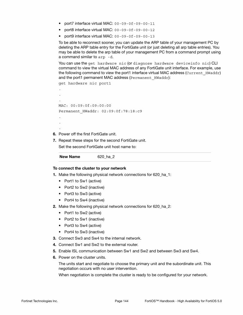
• port7 interface virtual MAC: 00-09-0f-09-00-11
• port8 interface virtual MAC: 00-09-0f-09-00-12
• port9 interface virtual MAC: 00-09-0f-09-00-13
To be able to reconnect sooner, you can update the ARP table of your management PC by deleting the ARP table entry for the FortiGate unit (or just deleting all arp table entries). You may be able to delete the arp table of your management PC from a command prompt using a command similar to arp -d.
You can use the get hardware nic (or diagnose hardware deviceinfo nic) CLI command to view the virtual MAC address of any FortiGate unit interface. For example, use the following command to view the port1 interface virtual MAC address (Current_HWaddr) and the port1 permanent MAC address (Permanent_HWaddr):get hardware nic port1
.
.
.
MAC: 00:09:0f:09:00:00
Permanent_HWaddr: 02:09:0f:78:18:c9
.
.
.
6. Power off the first FortiGate unit.
7. Repeat these steps for the second FortiGate unit.
Set the second FortiGate unit host name to:
To connect the cluster to your network
1. Make the following physical network connections for 620_ha_1:
• Port1 to Sw1 (active)
• Port2 to Sw2 (inactive)
• Port3 to Sw3 (active)
• Port4 to Sw4 (inactive)
2. Make the following physical network connections for 620_ha_2:
• Port1 to Sw2 (active)
• Port2 to Sw1 (inactive)
• Port3 to Sw4 (active)
• Port4 to Sw3 (inactive)
3. Connect Sw3 and Sw4 to the internal network.
4. Connect Sw1 and Sw2 to the external router.
5. Enable ISL communication between Sw1 and Sw2 and between Sw3 and Sw4.
6. Power on the cluster units.
The units start and negotiate to choose the primary unit and the subordinate unit. This negotiation occurs with no user intervention.
When negotiation is complete the cluster is ready to be configured for your network.
New Name 620_ha_2
Fortinet Technologies Inc. Page 144 FortiOS™ Handbook - High Availability for FortiOS 5.0

To view cluster status
Use the following steps to view the cluster dashboard and cluster members list to confirm that the cluster units are operating as a cluster.
1. View the system dashboard.
The System Information dashboard widget shows the Cluster Name (Rexample1.com) and the host names and serial numbers of the Cluster Members. The Unit Operation widget shows multiple cluster units.
2. Go to System > Config > HA to view the cluster members list.
The list shows two cluster units, their host names, their roles in the cluster, and their priorities. You can use this list to confirm that the cluster is operating normally.
To troubleshoot the cluster configuration
If the cluster members list and the dashboard does not display information for both cluster units the FortiGate units are not functioning as a cluster. See “Troubleshooting HA clusters” on page 112 to troubleshoot the cluster.
To add basic configuration settings and the redundant interfaces
Use the following steps to add a few basic configuration settings.
1. Log into the cluster web-based manager.
2. Go to System > Admin > Administrators.
3. For admin, select the Change Password icon
4. Enter and confirm a new password.
5. Select OK.
6. Go to Router > Static > Static Routes and temporarily delete the default route.
You cannot add an interface to a redundant interface if any settings (such as the default route) are configured for it.
7. Go to System > Network > Interfaces and select Create New and configure the redundant interface to connect to the Internet.
8. Select OK.
9. Select Create New and configure the redundant interface to connect to the internal network.
Name Port1_Port2
Type Redundant
Physical Interface Members
Selected Interfaces port1, port2
IP/Netmask 172.20.120.141/24
Name Port3_Port4
Type Redundant
Physical Interface Members
Selected Interfaces port3, port4
Fortinet Technologies Inc. Page 145 FortiOS™ Handbook - High Availability for FortiOS 5.0

10.Select OK.
The virtual MAC addresses of the FortiGate-620B interfaces change to the following. Notice that port1 and port2 both have the port1 virtual MAC address and port3 and port4 both have the port3 virtual MAC address:
• port1 interface virtual MAC: 00-09-0f-09-00-00
• port10 interface virtual MAC: 00-09-0f-09-00-01
• port11 interface virtual MAC: 00-09-0f-09-00-02
• port12 interface virtual MAC: 00-09-0f-09-00-03
• port13 interface virtual MAC: 00-09-0f-09-00-04
• port14 interface virtual MAC: 00-09-0f-09-00-05
• port15 interface virtual MAC: 00-09-0f-09-00-06
• port16 interface virtual MAC: 00-09-0f-09-00-07
• port17 interface virtual MAC: 00-09-0f-09-00-08
• port18 interface virtual MAC: 00-09-0f-09-00-09
• port19 interface virtual MAC: 00-09-0f-09-00-0a
• port2 interface virtual MAC: 00-09-0f-09-00-00 (same as port1)
• port20 interface virtual MAC: 00-09-0f-09-00-0c
• port3 interface virtual MAC: 00-09-0f-09-00-0d
• port4 interface virtual MAC: 00-09-0f-09-00-0d (same as port3)
• port5 interface virtual MAC: 00-09-0f-09-00-0f
• port6 interface virtual MAC: 00-09-0f-09-00-10
• port7 interface virtual MAC: 00-09-0f-09-00-11
• port8 interface virtual MAC: 00-09-0f-09-00-12
• port9 interface virtual MAC: 00-09-0f-09-00-13
11.Go to Router > Static > Static Routes.
12.Add the default route.
13.Select OK.
To configure HA port monitoring for the redundant interfaces
1. Go to System > Config > HA.
2. In the cluster members list, edit the primary unit.
IP/Netmask 10.11.101.100/24
Administrative Access HTTPS, PING, SSH
Destination IP/Mask 0.0.0.0/0.0.0.0
Gateway 172.20.120.2
Device Port1_Port2
Distance 10
Fortinet Technologies Inc. Page 146 FortiOS™ Handbook - High Availability for FortiOS 5.0
3. Configure the following port monitoring for the redundant interfaces:
4. Select OK.
Configuring FortiGate-620B units for HA operation - CLI
Each FortiGate-620B unit in the cluster must have the same HA configuration. Use the following procedure to configure the FortiGate-620B units for HA operation.
To configure the FortiGate-620B units for HA operation
1. Connect to the CLI of one of the FortiGate-620B units.
2. Enter a new Host Name for this FortiGate unit.config system global
set hostname 620_ha_1
end
3. Configure HA settings.config system ha
set mode a-a
set group-name Rexample1.com
set password RHA_pass_1
set hbdev port5 50 port6 50
end
The FortiGate unit negotiates to establish an HA cluster. When you select OK you may temporarily lose connectivity with the FortiGate unit as the HA cluster negotiates and the FGCP changes the MAC address of the FortiGate unit interfaces (see “Cluster virtual MAC addresses” on page 200). The MAC addresses of the FortiGate-620B interfaces change to the following virtual MAC addresses:
• port1 interface virtual MAC: 00-09-0f-09-00-00
• port10 interface virtual MAC: 00-09-0f-09-00-01
• port11 interface virtual MAC: 00-09-0f-09-00-02
• port12 interface virtual MAC: 00-09-0f-09-00-03
• port13 interface virtual MAC: 00-09-0f-09-00-04
• port14 interface virtual MAC: 00-09-0f-09-00-05
• port15 interface virtual MAC: 00-09-0f-09-00-06
• port16 interface virtual MAC: 00-09-0f-09-00-07
• port17 interface virtual MAC: 00-09-0f-09-00-08
• port18 interface virtual MAC: 00-09-0f-09-00-09
• port19 interface virtual MAC: 00-09-0f-09-00-0a
• port2 interface virtual MAC: 00-09-0f-09-00-0b
• port20 interface virtual MAC: 00-09-0f-09-00-0c
• port3 interface virtual MAC: 00-09-0f-09-00-0d
• port4 interface virtual MAC: 00-09-0f-09-00-0e
Port Monitor
Port1_Port2 Select
Port3_Port4 Select
Fortinet Technologies Inc. Page 147 FortiOS™ Handbook - High Availability for FortiOS 5.0

• port5 interface virtual MAC: 00-09-0f-09-00-0f
• port6 interface virtual MAC: 00-09-0f-09-00-10
• port7 interface virtual MAC: 00-09-0f-09-00-11
• port8 interface virtual MAC: 00-09-0f-09-00-12
• port9 interface virtual MAC: 00-09-0f-09-00-13
To be able to reconnect sooner, you can update the ARP table of your management PC by deleting the ARP table entry for the FortiGate unit (or just deleting all arp table entries). You may be able to delete the arp table of your management PC from a command prompt using a command similar to arp -d.
You can use the get hardware nic (or diagnose hardware deviceinfo nic) CLI command to view the virtual MAC address of any FortiGate unit interface. For example, use the following command to view the port1 interface virtual MAC address (Current_HWaddr) and the port1 permanent MAC address (Permanent_HWaddr):get hardware nic port1
.
.
.
MAC: 00:09:0f:09:00:00
Permanent_HWaddr: 02:09:0f:78:18:c9
.
.
.
4. Power off the first FortiGate unit.
5. Repeat these steps for the second FortiGate unit.
Set the other FortiGate unit host name to:config system global
set hostname 620_ha_2
end
To connect the cluster to your network
1. Make the following physical network connections for 620_ha_1:
• Port1 to Sw1 (active)
• Port2 to Sw2 (inactive)
• Port3 to Sw3 (active)
• Port4 to Sw4 (inactive)
2. Make the following physical network connections for 620_ha_2:
• Port1 to Sw2 (active)
• Port2 to Sw1 (inactive)
• Port3 to Sw4 (active)
• Port4 to Sw3 (inactive)
3. Connect Sw3 and Sw4 to the internal network.
4. Connect Sw1 and Sw2 to the external router.
5. Enable ISL communication between Sw1 and Sw2 and between Sw3 and Sw4.
6. Power on the cluster units.
The units start and negotiate to choose the primary unit and the subordinate unit. This negotiation occurs with no user intervention.
When negotiation is complete the cluster is ready to be configured for your network.
Fortinet Technologies Inc. Page 148 FortiOS™ Handbook - High Availability for FortiOS 5.0

To view cluster status
Use the following steps to view cluster status from the CLI.
1. Log into the CLI.
2. Enter get system status to verify the HA status of the cluster unit that you logged into.
If the command output includes Current HA mode: a-a, master, the cluster units are operating as a cluster and you have connected to the primary unit.
If the command output includes Current HA mode: a-a, backup, you have connected to a subordinate unit.
If the command output includes Current HA mode: standalone the cluster unit is not operating in HA mode.
3. Enter the following command to confirm the HA configuration of the cluster:get system ha status
Model: 620
Mode: a-a
Group: 0
Debug: 0
ses_pickup: disable
Master:128 620_ha_2 FG600B3908600825 0
Slave :128 620_ha_1 FG600B3908600705 1
number of vcluster: 1
vcluster 1: work 169.254.0.1
Master:0 FG600B3908600825
Slave :1 FG600B3908600705
The command output shows both cluster units, their host names, their roles in the cluster, and their priorities. You can use this command to confirm that the cluster is operating normally. For example, if the command shows only one cluster unit then the other unit has left the cluster for some reason.
4. Use the execute ha manage command to connect to the other cluster unit’s CLI and use these commands to verify cluster status.
To troubleshoot the cluster configuration
If the cluster members list and the dashboard does not display information for both cluster units the FortiGate units are not functioning as a cluster. See “Troubleshooting HA clusters” on page 112 to troubleshoot the cluster.
To add basic configuration settings and the redundant interfaces
Use the following steps to add a few basic configuration settings. Some steps use the CLI and some the web-based manager.
1. Log into the cluster CLI.
2. Add a password for the admin administrative account.config system admin
edit admin
set password <password_str>
end
Fortinet Technologies Inc. Page 149 FortiOS™ Handbook - High Availability for FortiOS 5.0

3. Temporarily delete the default route.
You cannot add an interface to a redundant interface if any settings (such as the default route) are configured for it.config router static
delete 1
end
4. Go to System > Network > Interface and select Create New to add the redundant interface to connect to the Internet.
5. Add the redundant interface to connect to the Internet.config sysetem interface
edit Port1_Port2
set type redundant
set member port1 port2
end
6. Add the redundant interface to connect to the internal network.config sysetem interface
edit Port3_Port4
set type redundant
set member port3 port4
end
The virtual MAC addresses of the FortiGate-620B interfaces change to the following. Note that port1 and port2 both have the port1 virtual MAC address and port3 and port4 both have the port3 virtual MAC address:
• port1 interface virtual MAC: 00-09-0f-09-00-00
• port10 interface virtual MAC: 00-09-0f-09-00-01
• port11 interface virtual MAC: 00-09-0f-09-00-02
• port12 interface virtual MAC: 00-09-0f-09-00-03
• port13 interface virtual MAC: 00-09-0f-09-00-04
• port14 interface virtual MAC: 00-09-0f-09-00-05
• port15 interface virtual MAC: 00-09-0f-09-00-06
• port16 interface virtual MAC: 00-09-0f-09-00-07
• port17 interface virtual MAC: 00-09-0f-09-00-08
• port18 interface virtual MAC: 00-09-0f-09-00-09
• port19 interface virtual MAC: 00-09-0f-09-00-0a
• port2 interface virtual MAC: 00-09-0f-09-00-00 (same as port1)
• port20 interface virtual MAC: 00-09-0f-09-00-0c
• port3 interface virtual MAC: 00-09-0f-09-00-0d
• port4 interface virtual MAC: 00-09-0f-09-00-0d (same as port3)
• port5 interface virtual MAC: 00-09-0f-09-00-0f
• port6 interface virtual MAC: 00-09-0f-09-00-10
• port7 interface virtual MAC: 00-09-0f-09-00-11
• port8 interface virtual MAC: 00-09-0f-09-00-12
• port9 interface virtual MAC: 00-09-0f-09-00-13
7. Go to Router > Static.
Fortinet Technologies Inc. Page 150 FortiOS™ Handbook - High Availability for FortiOS 5.0

8. Add the default route.config router static
edit 1
set dst 0.0.0.0 0.0.0.0
set gateway 172.20.120.2
set device Port1_Port2
end
To configure HA port monitoring for the redundant interfaces
1. Enter the following command to configure port monitoring for the redundant interfaces:config system ha
set monitor Port1_Port2 Port3_Port4
end
Troubleshooting full mesh HA
Troubleshooting full mesh HA clusters is similar to troubleshooting any cluster (see “Troubleshooting HA clusters” on page 112 or “Troubleshooting virtual clustering” on page 138). The configuration and operation of a full mesh HA cluster is very similar to the configuration and operation of a standard cluster. The only differences relate to the configuration, connection, and operation of the redundant interfaces and redundant switches.
• Make sure the redundant interfaces and switches are connected correctly. With so many connections it is possible to make mistakes or for cables to become disconnected.
• Confirm that the configuration of the cluster unit 802.3ad Aggregate or Redundant interfaces is correct according to the configuration procedures in this chapter.
• In some configurations with some switch hardware, MAC-learning delays on the inter-switch links on the surrounding topologies may occur. The delays occur if the gratuitous ARP packets sent by the cluster after a failover are delayed by the switches before being sent across the inter-switch link. If this happens the surrounding topologies may be delayed in recognizing the failover and will keep sending packets to the MAC address of the failed primary unit resulting in lost traffic. Resolving this problem may require changing the configuration of the switch or replacing them with switch hardware that does not delay the gratuitous ARP packets.
Fortinet Technologies Inc. Page 151 FortiOS™ Handbook - High Availability for FortiOS 5.0

Operating a cluster
With some exceptions, you can operate a cluster in much the same way as you operate a standalone FortiGate unit. This chapter describes those exceptions and also the similarities involved in operating a cluster instead of a standalone FortiGate unit.
This chapter contains the following sections:
• Operating a cluster
• Operating a virtual cluster
• Managing individual cluster units using a reserved management interface
• The primary unit acts as a router for subordinate unit management traffic
• Clusters and FortiGuard services
• Clusters and logging
• Clusters and SNMP
• Clusters and file quarantine
• Cluster members list
• Virtual cluster members list
• Viewing HA statistics
• Changing the HA configuration of an operating cluster
• Changing the HA configuration of an operating virtual cluster
• Changing the subordinate unit host name and device priority
• Upgrading cluster firmware
• Downgrading cluster firmware
• Backing up and restoring the cluster configuration
• Monitoring cluster units for failover
• Viewing cluster status from the CLI
• Disconnecting a cluster unit from a cluster
• Adding a disconnected FortiGate unit back to its cluster
Operating a cluster
The configurations of all of the FortiGate units in a cluster are synchronized so that the cluster units can simulate a single FortiGate unit. Because of this synchronization, you manage the HA cluster instead of managing the individual cluster units. You manage the cluster by connecting to the web-based manager using any cluster interface configured for HTTPS or HTTP administrative access. You can also manage the cluster by connecting to the CLI using any cluster interface configured for SSH or telnet administrative access.
The cluster web-based manager dashboard displays the cluster name, the host name and serial number of each cluster member, and also shows the role of each unit in the cluster. The roles can be master (primary unit) and slave (subordinate units). The dashboard also displays a cluster unit front panel illustration.
Page 152

Figure 17:Example cluster web-based manager dashboard
You can also go to System > Config > HA to view the cluster members list. This includes status information for each cluster unit. You can also use the cluster members list for a number of cluster management functions including changing the HA configuration of an operating cluster, changing the host name and device priority of a subordinate unit, and disconnecting a cluster unit from a cluster. See “Cluster members list” on page 168.
You can use log messages to view information about the status of the cluster. See “Viewing and managing log messages for individual cluster units” on page 161. You can use SNMP to manage the cluster by configuring a cluster interface for SNMP administrative access. Using an SNMP manager you can get cluster configuration information and receive traps.
You can configure a reserved management interface to manage individual cluster units. You can use this interface to access the web-based manager or CLI and to configure SNMP management for individual cluster units. See “Managing individual cluster units using a reserved management interface” on page 154.
You can manage individual cluster units by using SSH, telnet, or the CLI console on the web-based manager dashboard to connect to the CLI of the cluster. From the CLI you can use the execute ha manage command to connect to the CLI of any unit in the cluster.
You can also manage individual cluster units by using a null-modem cable to connect to any cluster unit CLI. From there you can use the execute ha manage command to connect to the CLI of each unit in the cluster.
Operating a virtual cluster
Managing a virtual cluster is very similar to managing a cluster that does not contain multiple virtual domains. Most of the information in this chapter applies to managing both kinds of clusters. This section describes what is different when managing a virtual cluster.
If virtual domains are enabled, the cluster web-based manager dashboard displays the cluster name and the role of each cluster unit in virtual cluster 1 and virtual cluster 2.
Fortinet Technologies Inc. Page 153 FortiOS™ Handbook - High Availability for FortiOS 5.0

Figure 18:Example virtual clustering web-based manager dashboard
The configuration and maintenance options that you have when you connect to a virtual cluster web-based manager or CLI depend on the virtual domain that you connect to and the administrator account that you use to connect.
If you connect to a cluster as the administrator of a virtual domain, you connect directly to the virtual domain. Since HA virtual clustering is a global configuration, virtual domain administrators cannot see HA configuration options. However, virtual domain administrators see the host name of the cluster unit that they are connecting to on the web browser title bar or CLI prompt. This host name is the host name of the primary unit for the virtual domain. Also, when viewing log messages by going to Log & Report > Log Access virtual domain administrator can select to view log messages for either of the cluster units.
If you connect to a virtual cluster as the admin administrator you connect to the global web-based manager or CLI. Even so, you are connecting to an interface and to the virtual domain that the interface has been added to. The virtual domain that you connect to does not make a difference for most configuration and maintenance operations. However, there are a few exceptions. You connect to the FortiGate unit that functions as the primary unit for the virtual domain. So the host name displayed on the web browser title bar and on the CLI is the host name of this primary unit.
Managing individual cluster units using a reserved management interface
You can provide direct management access to all cluster units by reserving a management interface as part of the HA configuration. Once this management interface is reserved, you can configure a different IP address, administrative access and other interface settings for this interface for each cluster unit. Then by connecting this interface of each cluster unit to your network you can manage each cluster unit separately from a different IP address. Configuration changes to the reserved management interface are not synchronized to other cluster units.
The reserved management interface provides direct management access to each cluster unit and gives each cluster unit a different identity on your network. This simplifies using external services, such as SNMP, to separately monitor and manage each cluster unit.
The reserved management interface and IP address should not be used for managing a cluster using FortiManager. To correctly manage a FortiGate HA cluster with FortiManager use the IP address of one of the cluster unit interfaces.
The reserved management interface is not assigned an HA virtual MAC address like other cluster interfaces. Instead the reserved management interface retains the permanent hardware address of the physical interface unless you change it using the config system interface command.
Fortinet Technologies Inc. Page 154 FortiOS™ Handbook - High Availability for FortiOS 5.0

If you enable SNMP administrative access for the reserved management interface you can use SNMP to monitor each cluster unit using the reserved management interface IP address. To monitor each cluster unit using SNMP, just add the IP address of each cluster unit’s reserved management interface to the SNMP server configuration. You must also enable direct management of cluster members in the cluster SNMP configuration.
If you enable HTTPS or HTTP administrative access for the reserved management interfaces you can connect to the web-based manager of each cluster unit. Any configuration changes made to any of the cluster units is automatically synchronized to all cluster units. From the subordinate units the web-based manager has the same features as the primary unit except that unit-specific information is displayed for the subordinate unit, for example:
• The Dashboard System Information widget displays the subordinate unit serial number but also displays the same information about the cluster as the primary unit
• On the Cluster members list (go to System > Config > HA) you can change the HA configuration of the subordinate unit that you are logged into. For the primary unit and other subordinate units you can change only the host name and device priority.
• Log Access displays the logs of the subordinate that you are logged into fist, You use the HA Cluster list to view the log messages of other cluster units including the primary unit.
If you enable SSH or TELNET administrative access for the reserved management interfaces you can connect to the CLI of each cluster unit. The CLI prompt contains the host name of the cluster unit that you have connected to. Any configuration changes made to any of the cluster units is automatically synchronized to all cluster units. You can also use the execute ha manage command to connect to other cluster unit CLIs.
The reserved management interface is available in NAT/Route and in Transparent mode. It is also available if the cluster is operating with multiple VDOMs. In Transparent mode you cannot normally add an IP address to an interface. However, you can add an IP address to the reserved management interface.
Configuring the reserved management interface and SNMP remote management of individual cluster units
This example describes how to configure SNMP remote management of individual cluster units using the HA reserved management interface. The configuration consists of two FortiGate-620B units already operating as a cluster. In the example, the port8 interface of each cluster unit is connected to the internal network using the switch and configured as the reserved management interface.
Fortinet Technologies Inc. Page 155 FortiOS™ Handbook - High Availability for FortiOS 5.0
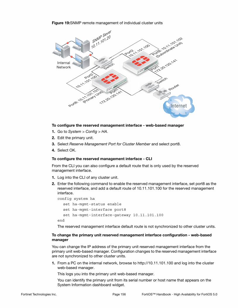
Figure 19:SNMP remote management of individual cluster units
To configure the reserved management interface - web-based manager
1. Go to System > Config > HA.
2. Edit the primary unit.
3. Select Reserve Management Port for Cluster Member and select port8.
4. Select OK.
To configure the reserved management interface - CLI
From the CLI you can also configure a default route that is only used by the reserved management interface.
1. Log into the CLI of any cluster unit.
2. Enter the following command to enable the reserved management interface, set port8 as the reserved interface, and add a default route of 10.11.101.100 for the reserved management interface. config system ha
set ha-mgmt-status enable
set ha-mgmt-interface port8
set ha-mgmt-interface-gateway 10.11.101.100
end
The reserved management interface default route is not synchronized to other cluster units.
To change the primary unit reserved management interface configuration - web-based manager
You can change the IP address of the primary unit reserved management interface from the primary unit web-based manager. Configuration changes to the reserved management interface are not synchronized to other cluster units.
1. From a PC on the internal network, browse to http://10.11.101.100 and log into the cluster web-based manager.
This logs you into the primary unit web-based manager.
You can identify the primary unit from its serial number or host name that appears on the System Information dashboard widget.
InternalNetwork
SNMP Sever
10.11.101.20
RouterSwitch
Port1
172.20.120.141
Port1
172.20.120.141
Port2
10.11.101.100
Port2
10.11.101.100
Port8: 10.11.101.101
(Primary Unit)
Port8: 10.11.101.102
(Subordinate Unit)
Switch
Sw
Switch
Fortinet Technologies Inc. Page 156 FortiOS™ Handbook - High Availability for FortiOS 5.0

2. Go to System > Network > Interfaces and edit the port8 interface as follows:
3. Select OK.
You can now log into the primary unit web-based manager by browsing to https://10.11.101.101. You can also log into this primary unit CLI by using an SSH client to connect to 10.11.101.101.
To change subordinate unit reserved management interface configuration - CLI
At this point you cannot connect to the subordinate unit reserved management interface because it does not have an IP address. Instead, this procedure describes connecting to the primary unit CLI and using the execute ha manage command to connect to subordinate unit CLI to change the port8 interface. You can also use a serial connection to the cluster unit CLI. Configuration changes to the reserved management interface are not synchronized to other cluster units.
1. Connect to the primary unit CLI and use the execute ha manage command to connect to a subordinate unit CLI.
You can identify the subordinate unit from is serial number or host name. The host name appears in the CLI prompt.
2. Enter the following command to change the port8 IP address to 10.11.101.102 and set management access to HTTPS, ping, SSH, and SNMP.config system interface
edit port8
set ip 10.11.101.102/24
set allowaccess https ping ssh snmp
end
You can now log into the subordinate unit web-based manager by browsing to https://10.11.101.102. You can also log into this subordinate unit CLI by using an SSH client to connect to 10.11.101.102.
To configure the cluster for SNMP management using the reserved management interfaces - CLI
This procedure describes how to configure the cluster to allow the SNMP server to get status information from the primary unit and the subordinate unit. The SNMP configuration is synchronized to all cluster units. To support using the reserved management interfaces, you must add at least one HA direct management host to an SNMP community. If your SNMP configuration includes SNMP users with user names and passwords you must also enable HA direct management for SNMP users.
Alias primary_reserved
IP/Netmask 10.11.101.101/24
Administrative Access Ping, SSH, HTTPS, SNMP
Fortinet Technologies Inc. Page 157 FortiOS™ Handbook - High Availability for FortiOS 5.0

1. Enter the following command to add an SNMP community called Community and add a host to the community for the reserved management interface of each cluster unit. The host includes the IP address of the SNMP server (10.11.101.20).config system snmp community
edit 1
set name Community
config hosts
edit 1
set ha-direct enable
set ip 10.11.101.20
end
end
2. Enter the following command to add an SNMP user for the reserved management interface.config system snmp user
edit 1
set ha-direct enable
set notify-hosts 10.11.101.20
end
Configure other settings as required.
To get CPU, memory, and network usage of each cluster unit using the reserved management IP addresses
From the command line of an SNMP manager, you can use the following SNMP commands to get CPU, memory and network usage information for each cluster unit. In the examples, the community name is Community. The commands use the MIB field names and OIDs listed in Table 3 on page 165.
Enter the following commands to get CPU, memory and network usage information for the primary unit with reserved management IP address 10.11.101.101 using the MIB fields:
snmpget -v2c -c Community 10.11.101.101 fgHaStatsCpuUsage
snmpget -v2c -c Community 10.11.101.101 fgHaStatsMemUsage
snmpget -v2c -c Community 10.11.101.101 fgHaStatsNetUsage
Enter the following commands to get CPU, memory and network usage information for the primary unit with reserved management IP address 10.11.101.101 using the OIDs:
snmpget -v2c -c Community 10.11.101.101 1.3.6.1.4.1.12356.101.13.2.1.1.3.1
snmpget -v2c -c Community 10.11.101.101 1.3.6.1.4.1.12356.101.13.2.1.1.4.1
snmpget -v2c -c Community 10.11.101.101 1.3.6.1.4.1.12356.101.13.2.1.1.5.1
Enter the following commands to get CPU, memory and network usage information for the subordinate unit with reserved management IP address 10.11.101.102 using the MIB fields:
snmpget -v2c -c Community 10.11.101.102 fgHaStatsCpuUsage
snmpget -v2c -c Community 10.11.101.102 fgHaStatsMemUsage
snmpget -v2c -c Community 10.11.101.102 fgHaStatsNetUsage
Fortinet Technologies Inc. Page 158 FortiOS™ Handbook - High Availability for FortiOS 5.0

Enter the following commands to get CPU, memory and network usage information for the subordinate unit with reserved management IP address 10.11.101.102 using the OIDs:
snmpget -v2c -c Community 10.11.101.102 1.3.6.1.4.1.12356.101.13.2.1.1.3.1
snmpget -v2c -c Community 10.11.101.102 1.3.6.1.4.1.12356.101.13.2.1.1.4.1
snmpget -v2c -c Community 10.11.101.102 1.3.6.1.4.1.12356.101.13.2.1.1.5.1
The primary unit acts as a router for subordinate unit management traffic
HA uses routing and inter-VDOM links to route subordinate unit management traffic through the primary unit to the network. Similar to a standalone FortiGate unit, subordinate units may generate their own management traffic, including:
• DNS queries.
• FortiGuard Web Filtering rating requests.
• Log messages to be sent to a FortiAnalyzer unit, to a syslog server, or to the FortiGuard Analysis and Management Service.
• Log file uploads to a FortiAnalyzer unit.
• Quarantine file uploads to a FortiAnalyzer unit.
• SNMP traps.
• Communication with remote authentication servers (RADIUS, LDAP, TACACS+ and so on)
Subordinate units send this management traffic over the HA heartbeat link to the primary unit. The primary unit forwards the management traffic to its destination. The primary unit also routes replies back to the subordinate unit in the same way.
HA uses a hidden VDOM called vsys_ha for HA operations. The vsys_ha VDOM includes the HA heartbeat interfaces, and all communication over the HA heartbeat link goes through the vsys_ha VDOM. To provide communication from a subordinate unit to the network, HA adds hidden inter-VDOM links between the primary unit management VDOM and the primary unit vsys_ha VDOM. By default, root is the management VDOM.
Management traffic from the subordinate unit originates in the subordinate unit vsys_ha VDOM. The vsys_ha VDOM routes the management traffic over the HA heartbeat link to the primary unit vsys_ha VDOM. This management traffic is then routed to the primary unit management VDOM and from there out onto the network.
DNS queries and FortiGuard Web Filtering and Email Filter requests are still handled by the HA proxy so the primary unit and subordinate units share the same DNS query cache and the same FortiGuard Web Filtering and Email Filter cache. In a virtual clustering configuration, the cluster unit that is the primary unit for the management virtual domain maintains the FortiGuard Web Filtering, Email Filtering, and DNS query cache.
Fortinet Technologies Inc. Page 159 FortiOS™ Handbook - High Availability for FortiOS 5.0
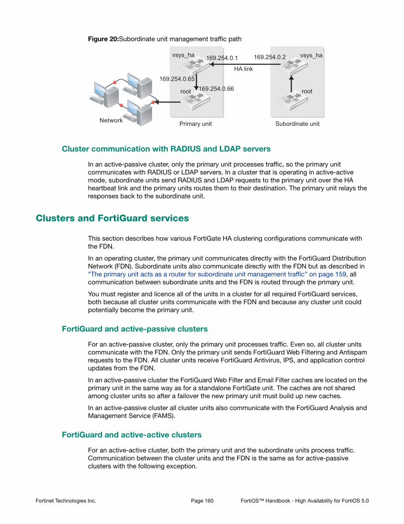
Figure 20:Subordinate unit management traffic path
Cluster communication with RADIUS and LDAP servers
In an active-passive cluster, only the primary unit processes traffic, so the primary unit communicates with RADIUS or LDAP servers. In a cluster that is operating in active-active mode, subordinate units send RADIUS and LDAP requests to the primary unit over the HA heartbeat link and the primary units routes them to their destination. The primary unit relays the responses back to the subordinate unit.
Clusters and FortiGuard services
This section describes how various FortiGate HA clustering configurations communicate with the FDN.
In an operating cluster, the primary unit communicates directly with the FortiGuard Distribution Network (FDN). Subordinate units also communicate directly with the FDN but as described in “The primary unit acts as a router for subordinate unit management traffic” on page 159, all communication between subordinate units and the FDN is routed through the primary unit.
You must register and licence all of the units in a cluster for all required FortiGuard services, both because all cluster units communicate with the FDN and because any cluster unit could potentially become the primary unit.
FortiGuard and active-passive clusters
For an active-passive cluster, only the primary unit processes traffic. Even so, all cluster units communicate with the FDN. Only the primary unit sends FortiGuard Web Filtering and Antispam requests to the FDN. All cluster units receive FortiGuard Antivirus, IPS, and application control updates from the FDN.
In an active-passive cluster the FortiGuard Web Filter and Email Filter caches are located on the primary unit in the same way as for a standalone FortiGate unit. The caches are not shared among cluster units so after a failover the new primary unit must build up new caches.
In an active-passive cluster all cluster units also communicate with the FortiGuard Analysis and Management Service (FAMS).
FortiGuard and active-active clusters
For an active-active cluster, both the primary unit and the subordinate units process traffic. Communication between the cluster units and the FDN is the same as for active-passive clusters with the following exception.
HA link
Primary unit Subordinate unit
vsys_ha
root
vsys_ha 169.254.0.1
169.254.0.65169.254.0.66
169.254.0.2
root
Network
Fortinet Technologies Inc. Page 160 FortiOS™ Handbook - High Availability for FortiOS 5.0

Because the subordinate units process traffic, they may also be making FortiGuard Web Filtering and Email Filter requests. The primary unit receives all such requests from the subordinate units and relays them to the FDN and then relays the FDN responses back to the subordinate units. The FortiGuard Web Filtering and Email Filtering URL caches are maintained on the primary unit. The primary unit caches are used for primary and subordinate unit requests.
FortiGuard and virtual clustering
For a virtual clustering configuration the management virtual domain of each cluster unit communicates with the FDN. The cluster unit that is the primary unit for the management virtual domain maintains the FortiGuard Web Filtering and Email Filtering caches. All FortiGuard Web Filtering and Email Filtering requests are proxied by the management VDOM of the cluster unit that is the primary unit for the management virtual domain.
Clusters and logging
This section describes the log messages that provide information about how HA is functioning, how to view and manage logs for each unit in a cluster, and provides some example log messages that are recorded during specific cluster events.
You configure logging for a cluster in the same way as you configuring logging for a standalone FortiGate unit. Log configuration changes made to the cluster are synchronized to all cluster units.
All cluster units record log messages separately to the individual cluster unit’s log disk, to the cluster unit’s system memory, or both. You can view and manage log messages for each cluster unit from the cluster web-based manager Log Access page.
When remote logging is configured, all cluster units send log messages to remote FortiAnalyzer units or other remote servers as configured. HA uses routing and inter-VDOM links to route subordinate unit log traffic through the primary unit to the network. See “The primary unit acts as a router for subordinate unit management traffic” on page 159.
When you configure a FortiAnalyzer unit to receive log messages from a FortiGate cluster, you should add a cluster to the FortiAnalyzer unit configuration so that the FortiAnalyzer unit can receive log messages from all cluster units.
Viewing and managing log messages for individual cluster units
This section describes how to view and manage log messages for an individual cluster unit.
To view HA cluster log messages
1. Log into the cluster web-based manager.
2. Go to Log&Report > Log Access and select Memory or Disk.
For each log display, the HA Cluster list displays the serial number of the cluster unit for which log messages are displayed. The serial numbers are displayed in order in the list.
3. Set HA Cluster to the serial number of one of the cluster units to display log messages for that unit.
You can view logs saved to memory or logs saved to the hard disk for the cluster unit.
About HA event log messages
HA event log messages always include the host name and serial number of the cluster unit that recorded the message. HA event log messages also include the HA state of the unit and also
Fortinet Technologies Inc. Page 161 FortiOS™ Handbook - High Availability for FortiOS 5.0

indicate when a cluster unit switches (or moves) from one HA state to another. Cluster units can operate in the HA states listed in Table 2:
HA log Event log messages also indicate the virtual cluster that the cluster unit is operating in as well as the member number of the unit in the cluster. If virtual domains are not enabled, all clusters unit are always operating in virtual cluster 1. If virtual domains are enabled, a cluster unit may be operating in virtual cluster 1 or virtual cluster 2. The member number indicates the position of the cluster unit in the cluster members list. Member 0 is the primary unit. Member 1 is the first subordinate unit, member 2 is the second subordinate unit, and so on.
HA log messages
See the FortiGate Log Message Reference for a listing of and descriptions of the HA log messages.
Fortigate HA message "HA master heartbeat interface <intf_name> lost neighbor information"
The following HA log messages may be recorded by an operating cluster:
2009-02-16 11:06:34 device_id=FG2001111111 log_id=0105035001 type=event subtype=ha pri=critical vd=root msg="HA slave heartbeat interface internal lost neighbor information"
2009-02-16 11:06:40 device_id=FG2001111111 log_id=0105035001 type=event subtype=ha pri=notice vd=root msg="Virtual cluster 1 of group 0 detected new joined HA member"
2009-02-16 11:06:40 device_id=FG2001111111 log_id=0105035001 type=event subtype=ha pri=notice vd=root msg="HA master heartbeat interface internal get peer information"
These log messages indicate that the cluster units could not connect to each other over the HA heartbeat link for the period of time that is given by hb-interval x hb-lost-threshold, which is 1.2 seconds with the default values.
To diagnose this problem
1. Check all heartbeat interface connections including cables and switches to make sure they are connected and operating normally.
2. Use the following commands to display the status of the heartbeat interfaces.get hardware nic <heartbeat_interface_name>
diagnose hardware deviceinfo nic <heartbeat_interface_name>
The status information may indicate the interface status and link status and also indicate if a large number of errors have been detected.
Table 2: HA states
Hello A FortiGate unit configured for HA operation has started up and is looking for other FortiGate units with which to form a cluster.
Work In an active-passive cluster a cluster unit is operating as the primary unit. In an active-active cluster unit is operating as the primary unit or a subordinate unit.
Standby In an active-passive cluster the cluster unit is operating as a subordinate unit.
Fortinet Technologies Inc. Page 162 FortiOS™ Handbook - High Availability for FortiOS 5.0

3. If the log message only appears during peak traffic times, increase the tolerance for missed HA heartbeat packets by using the following commands to increase the lost heartbeat threshold and heartbeat interval:config system ha
set hb-lost-threshold 12
set hb-interval 4
end
These settings multiply by 4 the loss detection interval. You can use higher values as well.
This condition can also occur if the cluster units are located in different buildings or even different geographical locations. Called a distributed cluster, as a result of the separation it may take a relatively long time for heartbeat packets to be transmitted between cluster units. You can support a distributed cluster by increasing the heartbeat interval so that the cluster expects extra time between heartbeat packets.
4. Optionally disable session-pickup to reduce the processing load on the heartbeat interfaces.
5. Instead of disabling session-pickup you can enable session-pickup-delay to reduce the number of sessions that are synchronized. With this option enabled only sessions that are active for more than 30 seconds are synchronized.
It may be useful to monitor CPU and memory usage to check for low memory and high CPU usage. You can configure event logging to monitor CPU and memory usage. You can also enable the CPU over usage and memory low SNMP events.
Once this monitoring is in place, try and determine if there have been any changes in the network or an increase of traffic recently that could be the cause. Check to see if the problem happens frequently and if so what the pattern is.
To monitor the CPU of the cluster units and troubleshoot further, use the following procedure and commands:
get system performance status
get sys performance top 2
diagnose sys top 2
These commands repeated at frequent intervals will show the activity of the CPU and the number of sessions.
Search the Fortinet Knowledge Base for articles about monitoring CPU and Memory usage.
If the problem persists, gather the following information (a console connection might be necessary if connectivity is lost) and provide it to Technical Support when opening a ticket:
• Debug log from the web-based manager: System > Config > Advanced > Download Debug Log
• CLI command output:diag sys top 2 (keep it running for 20 seconds)get sys perf status (repeat this command multiple times to get good samples)get sys ha status
diagnose sys ha status
diagnose sys ha dump-by {all options}
diagnose netlink device list
diagnose hardware deviceinfo nic <heartbeat-interface-name>
execute log filter category 1
execute log display
Fortinet Technologies Inc. Page 163 FortiOS™ Handbook - High Availability for FortiOS 5.0

Formatting cluster unit hard disks (log disks)
If you need to format the hard disk (also called log disk or disk storage) of one or more cluster units you should disconnect the unit from the cluster and use the execute formatlogdisk command to format the cluster unit hard disk then add the unit back to the cluster.
For information about how to remove a unit from a cluster and add it back, see “Disconnecting a cluster unit from a cluster” on page 185 and “Adding a disconnected FortiGate unit back to its cluster” on page 186.
Once you add the cluster unit with the formatted log disk back to the cluster you should make it the primary unit before removing other units from the cluster to format their log disks and then add them back to the cluster.
Clusters and SNMP
You can use SNMP to manage a cluster by configuring a cluster interface for SNMP administrative access. Using an SNMP manager you can get cluster configuration and status information and receive traps.
You configure SNMP for a cluster in the same way as configuring SNMP for a standalone FortiGate unit. SNMP configuration changes made to the cluster are shared by all cluster units.
Each cluster unit sends its own traps and SNMP manager systems can use SNMP get commands to query each cluster unit separately. To set SNMP get queries to each cluster unit you must create a special get command that includes the serial number of the cluster unit.
Alternatively you can use the HA reserved management interface feature to give each cluster unit a different management IP address. Then you can create an SNMP get command for each cluster unit that just includes the management IP address and does not have to include the serial number. See “Managing individual cluster units using a reserved management interface” on page 154.
SNMP get command syntax for the primary unit
Normally, to get configuration and status information for a standalone FortiGate unit or for a primary unit, an SNMP manager would use an SNMP get commands to get the information in a MIB field. The SNMP get command syntax would be similar to the following:
snmpget -v2c -c <community_name> <address_ipv4> {<OID> | <MIB_field>}
where:
<community_name> is an SNMP community name added to the FortiGate configuration. You can add more than one community name to a FortiGate SNMP configuration. The most commonly used community name is public.
<address_ipv4> is the IP address of the FortiGate interface that the SNMP manager connects to.
{<OID> | <MIB_field>} is the object identifier (OID) for the MIB field or the MIB field name itself. The HA MIB fields and OIDs are listed in Table 3.
Fortinet Technologies Inc. Page 164 FortiOS™ Handbook - High Availability for FortiOS 5.0

Table 3: SNMP field names and OIDs
MIB field OID Description
fgHaSystemMode .1.3.6.1.4.1.12356.101.13.1.1.0 HA mode (standalone, a-a, or a-p)
fgHaGroupId .1.3.6.1.4.1.12356.101.13.1.2.0 The HA priority of the cluster unit. Default 128.
fgHaPriority .1.3.6.1.4.1.12356.101.13.1.3.0 The HA priority of the cluster unit. Default 128.
fgHaOverride .1.3.6.1.4.1.12356.101.13.1.4.0 Whether HA override is disabled or enabled for the cluster unit.
fgHaAutoSync .1.3.6.1.4.1.12356.101.13.1.5.0 Whether automatic HA synchronization is disabled or enabled.
fgHaSchedule .1.3.6.1.4.1.12356.101.13.1.6.0 The HA load balancing schedule. Set to none unless operating in a-p mode.
fgHaGroupName .1.3.6.1.4.1.12356.101.13.1.7.0 The HA group name.
fgHaStatsIndex .1.3.6.1.4.1.12356.101.13.2.1.1.1.1 The cluster index of the cluster unit. 1 for the primary unit, 2 to x for the subordinate units.
fgHaStatsSerial .1.3.6.1.4.1.12356.101.13.2.1.1.2.1 The serial number of the cluster unit.
fgHaStatsCpuUsage .1.3.6.1.4.1.12356.101.13.2.1.1.3.1 The cluster unit’s current CPU usage.
fgHaStatsMemUsage .1.3.6.1.4.1.12356.101.13.2.1.1.4.1 The cluster unit’s current Memory usage.
fgHaStatsNetUsage .1.3.6.1.4.1.12356.101.13.2.1.1.5.1 The cluster unit’s current Network bandwidth usage.
fgHaStatsSesCount .1.3.6.1.4.1.12356.101.13.2.1.1.6.1 The cluster unit’s current session count.
fgHaStatsPktCount .1.3.6.1.4.1.12356.101.13.2.1.1.7.1 The cluster unit’s current packet count.
fgHaStatsByteCount .1.3.6.1.4.1.12356.101.13.2.1.1.8.1 The cluster unit’s current byte count.
fgHaStatsIdsCount .1.3.6.1.4.1.12356.101.13.2.1.1.9.1 The number of attacks reported by the IPS for the cluster unit.
Fortinet Technologies Inc. Page 165 FortiOS™ Handbook - High Availability for FortiOS 5.0

To get the HA priority for the primary unit
The following SNMP get command gets the HA priority for the primary unit. The community name is public. The IP address of the cluster interface configured for SNMP management access is 10.10.10.1. The HA priority MIB field is fgHaPriority and the OID for this MIB field is 1.3.6.1.4.1.12356.101.13.1.3.0 The first command uses the MIB field name and the second uses the OID:
snmpget -v2c -c public 10.10.10.1 fgHaPriority
snmpget -v2c -c public 10.10.10.1 1.3.6.1.4.1.12356.101.13.1.3.0
SNMP get command syntax for any cluster unit
To get configuration status information for a specific cluster unit (for the primary unit or for any subordinate unit), the SNMP manager must add the serial number of the cluster unit to the SNMP get command after the community name. The community name and the serial number are separated with a dash. The syntax for this SNMP get command would be:
snmpget -v2c -c <community_name>-<fgt_serial> <address_ipv4> {<OID> | <MIB_field>}
where:
<community_name> is an SNMP community name added to the FortiGate configuration. You can add more than one community name to a FortiGate SNMP configuration. All units in the cluster have the same community name. The most commonly used community name is public.
<fgt_serial> is the serial number of any cluster unit. For example, FGT4002803033172. You can specify the serial number of any cluster unit, including the primary unit, to get information for that unit.
<address_ipv4> is the IP address of the FortiGate interface that the SNMP manager connects to.
If the serial number matches the serial number of a subordinate unit, the SNMP get request is sent over the HA heartbeat link to the subordinate unit. After processing the request, the subordinate unit sends the reply back over the HA heartbeat link back to the primary unit. The primary unit then forwards the response back to the SNMP manager.
If the serial number matches the serial number of the primary unit, the SNMP get request is processed by the primary unit. You can actually add a serial number to the community name of any SNMP get request. But normally you only need to do this for getting information from a subordinate unit.
To get the CPU usage for a subordinate unit
The following SNMP get command gets the CPU usage for a subordinate unit in a FortiGate-5001SX cluster. The subordinate unit has serial number FG50012205400050. The community name is public. The IP address of the FortiGate interface is 10.10.10.1. The HA status table MIB field is fgHaStatsCpuUsage and the OID for this MIB field is
fgHaStatsAvCount .1.3.6.1.4.1.12356.101.13.2.1.1.10.1
The number of viruses reported by the antivirus system for the cluster unit.
fgHaStatsHostname .1.3.6.1.4.1.12356.101.13.2.1.1.11.1
The hostname of the cluster unit.
Table 3: SNMP field names and OIDs
MIB field OID Description
Fortinet Technologies Inc. Page 166 FortiOS™ Handbook - High Availability for FortiOS 5.0

1.3.6.1.4.1.12356.101.13.2.1.1.3.1. The first command uses the MIB field name and the second uses the OID for this table:
snmpget -v2c -c public-FG50012205400050 10.10.10.1 fgHaStatsCpuUsage
snmpget -v2c -c public-FG50012205400050 10.10.10.1 1.3.6.1.4.1.12356.101.13.2.1.1.3.1
FortiGate SNMP recognizes the community name with syntax <community_name>-<fgt_serial>. When the primary unit receives an SNMP get request that includes the community name followed by serial number, the FGCP extracts the serial number from the request. Then the primary unit redirects the SNMP get request to the cluster unit with that serial number. If the serial number matches the serial number of the primary unit, the SNMP get is processed by the primary unit.
Getting serial numbers of cluster units
The following SNMP get commands use the MIB field name fgHaStatsSerial.<index> to get the serial number of each cluster unit. Where <index> is the cluster unit’s cluster index and 1 is the cluster index of the primary unit, 2 is the cluster index of the first subordinate unit, and 3 is the cluster index of the second subordinate unit.
The OID for this MIB field is 1.3.6.1.4.1.12356.101.13.2.1.1.2.1. The community name is public. The IP address of the FortiGate interface is 10.10.10.1.
The first command uses the MIB field name and the second uses the OID for this table and gets the serial number of the primary unit:
snmpget -v2c -c public 10.10.10.1 fgHaStatsSerial.1
snmpget -v2c -c public 10.10.10.1 1.3.6.1.4.1.12356.101.13.2.1.1.2.1
The second command uses the MIB field name and the second uses the OID for this table and gets the serial number of the first subordinate unit:
snmpget -v2c -c public 10.10.10.1 fgHaStatsSerial.2
snmpget -v2c -c public 10.10.10.1 1.3.6.1.4.1.12356.101.13.2.2.2
SNMP get command syntax - reserved management interface enabled
To get configuration and status information for any cluster unit where you have enabled the HA reserved management interface feature and assigned IP addresses to the management interface of each cluster unit, an SNMP manager would use the following get command syntax:
snmpget -v2c -c <community_name> <mgt_address_ipv4> {<OID> | <MIB_field>}
where:
<community_name> is an SNMP community name added to the FortiGate configuration. You can add more than one community names to a FortiGate SNMP configuration. The most commonly used community name is public.
<mgt_address_ipv4> is the IP address of the FortiGate HA reserved management interface that the SNMP manager connects to.
{<OID> | <MIB_field>} is the object identifier (OID) for the MIB field or the MIB field name itself. To find OIDs and MIB field names see your FortiGate unit’s online help.
See “To get CPU, memory, and network usage of each cluster unit using the reserved management IP addresses” on page 158.
Fortinet Technologies Inc. Page 167 FortiOS™ Handbook - High Availability for FortiOS 5.0

Clusters and file quarantine
You can configure file quarantine for a cluster in the same way as configuring file quarantine for a standalone FortiGate unit. Quarantine configuration changes made to the cluster are shared by all cluster units.
In an active-active cluster, both the primary unit and the subordinate units accept antivirus sessions and may quarantine files. In an active-passive cluster, only the primary unit quarantines files. Multiple cluster units in an active-passive cluster may have quarantined files if different cluster units have been the primary unit.
All cluster units quarantine files separately to their own hard disk. You can go to Log&Report > Archive Access > Quarantine to view and manage the quarantine file list for each cluster unit.
All cluster units can also quarantine files to a FortiAnalyzer unit. When you configure a FortiAnalyzer unit to receive quarantine files from a cluster, you should add each cluster unit to the FortiAnalyzer device configuration so that the FortiAnalyzer unit can receive quarantine files from all cluster units.
Cluster members list
Display the cluster members list to view the status of the FortiGate units in an operating cluster. To display the cluster members list, go to System > Config > HA.
From the cluster members list you can also:
• View HA statistics (see “Viewing HA statistics” on page 171).
• View and optionally change the HA configuration of the operating cluster (see “Changing the HA configuration of an operating cluster” on page 173).
• View and optionally change the host name and device priority of a subordinate unit (see “Changing the subordinate unit host name and device priority” on page 173).
• Disconnect a cluster unit from a cluster (see “Disconnecting a cluster unit from a cluster” on page 185).
• Download the Debug log for any cluster unit. You can send this debug log file to Fortinet Technical Support to help diagnose problems with the cluster or with individual cluster units.
Fortinet Technologies Inc. Page 168 FortiOS™ Handbook - High Availability for FortiOS 5.0

Figure 21:Example cluster members list
View HA Statistics Display the serial number, status, and monitor information for each cluster unit. See “Viewing HA statistics” on page 171.
Up and down arrows Change the order in which cluster members are listed. The operation of the cluster or of the units in the cluster are not affected. All that changes is the order in which cluster units are displayed on the cluster members list.
Cluster member Illustrations of the front panels of the cluster units. If the network jack for an interface is shaded green, the interface is connected. Pause the mouse pointer over each illustration to view the cluster unit host name, serial number, and how long the unit has been operating (up time). The list of monitored interfaces is also displayed.
Hostname The host name of the FortiGate unit. The default host name of the FortiGate unit is the FortiGate unit serial number.
• To change the primary unit host name, go to the system dashboard and select Change beside the current host name int System Information widget.
• To change a subordinate unit host name, from the cluster members list select the edit icon for a subordinate unit.
Role The status or role of the cluster unit in the cluster.
• Role is MASTER for the primary (or master) unit
• Role is SLAVE for all subordinate (or backup) cluster units
Priority The device priority of the cluster unit. Each cluster unit can have a different device priority. During HA negotiation, the unit with the highest device priority becomes the primary unit.
The device priority range is 0 to 255. The default device priority is 128.
Disconnect from cluster
Disconnect the cluster unit from the cluster. See “Disconnecting a cluster unit from a cluster” on page 185.
Disconnect from ClusterEdit
Download Debug LogUp and DownArrows
Fortinet Technologies Inc. Page 169 FortiOS™ Handbook - High Availability for FortiOS 5.0

Virtual cluster members list
If virtual domains are enabled, you can display the cluster members list to view the status of the operating virtual clusters. The virtual cluster members list shows the status of both virtual clusters including the virtual domains added to each virtual cluster.
To display the virtual cluster members list for an operating cluster log in as the admin administrator, select Global Configuration and go to System > Config > HA.
Edit Select Edit to change a cluster unit HA configuration.
• For a primary unit, select Edit to change the cluster HA configuration. You can also change the device priority of the primary unit.
• For a primary unit in a virtual cluster, select Edit to change the virtual cluster HA configuration. You can also change the virtual cluster 1 and virtual cluster 2 device priority of this cluster unit.
• For a subordinate unit, select Edit to change the subordinate unit host name and device priority. See “Changing the subordinate unit host name and device priority” on page 173.
• For a subordinate unit in a virtual cluster, select Edit to change the subordinate unit host name. In addition you can change the device priority for the subordinate unit for the selected virtual cluster.
Download debug log Download an encrypted debug log to a file. You can send this debug log file to Fortinet Technical Support to help diagnose problems with the cluster or with individual cluster units.
Fortinet Technologies Inc. Page 170 FortiOS™ Handbook - High Availability for FortiOS 5.0

Figure 22:Example FortiGate-5001SX virtual cluster members list
The fields and functions of the virtual cluster members list are the same as the fields and functions described in “Cluster members list” on page 168 with the following exceptions.
• When you select the edit icon for a primary unit in a virtual cluster, you can change the virtual cluster 1 and virtual cluster 2 device priority of this cluster unit and you can edit the VDOM partitioning configuration of the cluster.
• When you select the edit icon for a subordinate unit in a virtual cluster, you can change the device priority for the subordinate unit for the selected virtual cluster.
Also, the HA cluster members list changes depending on the cluster unit. For the virtual cluster described in the “Example: virtual clustering with two VDOMs and VDOM partitioning” on page 121 if you connect to port5 using you are connecting to 620b_ha_2 (620b_ha_2 is displayed on the web browser title bar or in the CLI prompt).
If you connect to port1 you are connecting to 620b_ha_1 (620b_ha_2 is displayed on the web browser title bar or in the CLI prompt).
Viewing HA statistics
From the cluster members list you can select View HA statistics to display the serial number, status, and monitor information for each cluster unit. To view HA statistics, go to System > Config > HA and select View HA Statistics.
Disconnect from Cluster
Up and DownArrows
Edit
Download Debug Log
Fortinet Technologies Inc. Page 171 FortiOS™ Handbook - High Availability for FortiOS 5.0
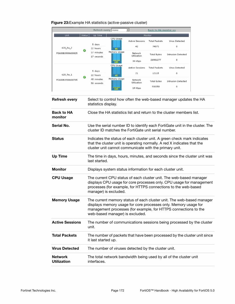
Figure 23:Example HA statistics (active-passive cluster)
Refresh every Select to control how often the web-based manager updates the HA statistics display.
Back to HA monitor
Close the HA statistics list and return to the cluster members list.
Serial No. Use the serial number ID to identify each FortiGate unit in the cluster. The cluster ID matches the FortiGate unit serial number.
Status Indicates the status of each cluster unit. A green check mark indicates that the cluster unit is operating normally. A red X indicates that the cluster unit cannot communicate with the primary unit.
Up Time The time in days, hours, minutes, and seconds since the cluster unit was last started.
Monitor Displays system status information for each cluster unit.
CPU Usage The current CPU status of each cluster unit. The web-based manager displays CPU usage for core processes only. CPU usage for management processes (for example, for HTTPS connections to the web-based manager) is excluded.
Memory Usage The current memory status of each cluster unit. The web-based manager displays memory usage for core processes only. Memory usage for management processes (for example, for HTTPS connections to the web-based manager) is excluded.
Active Sessions The number of communications sessions being processed by the cluster unit.
Total Packets The number of packets that have been processed by the cluster unit since it last started up.
Virus Detected The number of viruses detected by the cluster unit.
Network Utilization
The total network bandwidth being used by all of the cluster unit interfaces.
Fortinet Technologies Inc. Page 172 FortiOS™ Handbook - High Availability for FortiOS 5.0

Changing the HA configuration of an operating cluster
To change the configuration settings of an operating cluster, go to System > Config > HA to display the cluster members list. Select Edit for the master (or primary) unit in the cluster members list to display the HA configuration page for the cluster.
You can use the HA configuration page to check and fine tune the configuration of the cluster after the cluster is up and running. For example, if you connect or disconnect cluster interfaces you may want to change the Port Monitor configuration.
Any changes you make on this page, with the exception of changes to the device priority, are first made to the primary unit configuration and then synchronized to the subordinate units. Changing the device priority only affects the primary unit.
Changing the HA configuration of an operating virtual cluster
To change the configuration settings of the primary unit in a functioning cluster with virtual domains enabled, log in as the admin administrator, select Global Configuration and go to System > Config > HA to display the cluster members list. Select Edit for the master (or primary) unit in virtual cluster 1 or virtual cluster 2 to display the HA configuration page for the virtual cluster.
You can use the virtual cluster HA configuration page to check and fine tune the configuration of both virtual clusters after the cluster is up and running. For example, you may want to change the Port Monitor configuration for virtual cluster 1 and virtual cluster 2 so that each virtual cluster monitors its own interfaces.
You can also use this configuration page to move virtual domains between virtual cluster 1 and virtual cluster 2. Usually you would distribute virtual domains between the two virtual clusters to balance the amount of traffic being processed by each virtual cluster.
Any changes you make on this page, with the exception of changes to the device priorities, are first made to the primary unit configuration and then synchronized to the subordinate unit.
You can also adjust device priorities to configure the role of this cluster unit in the virtual cluster. For example, to distribute traffic to both cluster units in the virtual cluster configuration, you would want one cluster unit to be the primary unit for virtual cluster 1 and the other cluster unit to be the primary unit for virtual cluster 2. You can create this configuration by setting the device priorities. The cluster unit with the highest device priority in virtual cluster 1 becomes the primary unit for virtual cluster 1. The cluster unit with the highest device priority in virtual cluster 2 becomes the primary unit in virtual cluster 2.
Changing the subordinate unit host name and device priority
To change the host name and device priority of a subordinate unit in an operating cluster, go to System > Config > HA to display the cluster members list. Select Edit for any slave (subordinate) unit in the cluster members list.
Total Bytes The number of bytes that have been processed by the cluster unit since it last started up.
Intrusion Detected The number of intrusions or attacks detected by Intrusion Protection running on the cluster unit.
Fortinet Technologies Inc. Page 173 FortiOS™ Handbook - High Availability for FortiOS 5.0
To change the host name and device priority of a subordinate unit in an operating cluster with virtual domains enabled, log in as the admin administrator, select Global Configuration and go to System > Config > HA to display the cluster members list. Select Edit for any slave (subordinate) unit in the cluster members list.
You can change the host name (Peer) and device priority (Priority) of this subordinate unit. These changes only affect the configuration of the subordinate unit.
The device priority is not synchronized among cluster members. In a functioning cluster you can change device priority to change the priority of any unit in the cluster. The next time the cluster negotiates, the cluster unit with the highest device priority becomes the primary unit.
The device priority range is 0 to 255. The default device priority is 128.
Upgrading cluster firmware
You can upgrade the FortiOS firmware running on an HA cluster in the same manner as upgrading the firmware running on a standalone FortiGate unit. During a normal firmware upgrade, the cluster upgrades the primary unit and all subordinate units to run the new firmware image. The firmware upgrade takes place without interrupting communication through the cluster.
To upgrade the firmware without interrupting communication through the cluster, the cluster goes through a series of steps that involve first upgrading the firmware running on the subordinate units, then making one of the subordinate units the primary unit, and finally upgrading the firmware on the former primary unit. These steps are transparent to the user and the network, but depending upon your HA configuration may result in the cluster selecting a new primary unit.
The following sequence describes in detail the steps the cluster goes through during a firmware upgrade and how different HA configuration settings may affect the outcome.
1. The administrator uploads a new firmware image from the web-based manager or CLI.
2. If the cluster is operating in active-active mode load balancing is turned off.
3. The cluster upgrades the firmware running on all of the subordinate units.
4. Once the subordinate units have been upgraded, a new primary unit is selected.
This primary unit will be running the new upgraded firmware.
5. The cluster now upgrades the firmware of the former primary unit.
If the age of the new primary unit is more than 300 seconds (5 minutes) greater than the age of all other cluster units, the new primary unit continues to operate as the primary unit.
This is the intended behavior but does not usually occur because the age difference of the cluster units is usually less than the cluster age difference margin of 300 seconds. So instead, the cluster negotiates again to select a primary unit as described in “Primary unit selection” on page 31.
You can keep the cluster from negotiating again by reducing the cluster age difference margin using the ha-uptime-diff-margin option. However, you should be cautious when reducing the age or other problems may occur. For information about the cluster age difference margin, see “Cluster age difference margin (grace period)” on page 33). For more
Upgrading cluster firmware to a new major release (for example upgrading from 3.0 MRx to 4.0 MRx) is supported for clusters. Make sure you are taking an upgrade path described in the release notes. Even so you should back up your configuration and only perform such a firmware upgrade during a maintenance window.
Fortinet Technologies Inc. Page 174 FortiOS™ Handbook - High Availability for FortiOS 5.0

information about changing the cluster age margin, see “Changing the cluster age difference margin” on page 33.
6. If the cluster is operating in active-active mode, load balancing is turned back on.
Changing how the cluster processes firmware upgrades
By default cluster firmware upgrades proceed as uninterruptable upgrades that do not interrupt traffic flow. If required, you can use the following CLI command to change how the cluster handles firmware upgrades. You might want to change this setting if you are finding uninterruptable upgrades take too much time.
config system ha
set uninterruptible-upgrade disable
end
uninterruptible-upgrade is enabled by default. If you disable uninterruptible-upgrade the cluster still upgrades the firmware on all cluster units, but all cluster units are upgraded at once; which takes less time but interrupts communication through the cluster.
Synchronizing the firmware build running on a new cluster unit
If the firmware build running on a FortiGate unit that you add to a cluster is older than the cluster firmware build, you may be able to use the following steps to synchronize the firmware running on the new cluster unit.
This procedure describes re-installing the same firmware build on a cluster to force the cluster to upgrade all cluster units to the same firmware build.
Due to firmware upgrade and synchronization issues, in some cases this procedure may not work. In all cases it will work to install the same firmware build on the new unit as the one that the cluster is running before adding the new unit to the cluster.
To synchronize the firmware build running on a new cluster unit
1. Obtain a firmware image that is the same as build already running on the cluster.
2. Connect to the cluster using the web-based manager.
3. Go to the System Information dashboard widget.
4. Select Update beside Firmware Version.
You can also install a newer firmware build.
5. Select OK.
After the firmware image is uploaded to the cluster, the primary unit upgrades all cluster units to this firmware build.
Downgrading cluster firmware
For various reasons you may need to downgrade the firmware that a cluster is running. You can use the information in this section to downgrade the firmware version running on a cluster.
In most cases you can downgrade the firmware on an operating cluster using the same steps as for a firmware upgrade. A warning message appears during the downgrade but the downgrade usually works and after the downgrade the cluster continues operating normally with the older firmware image.
Fortinet Technologies Inc. Page 175 FortiOS™ Handbook - High Availability for FortiOS 5.0

Downgrading between some firmware versions, especially if features have changed between the two versions, may not always work without the requirement to fix configuration issues after the downgrade.
Only perform firmware downgrades during maintenance windows and make sure you back up your cluster configuration before the downgrade.
If the firmware downgrade that you are planning may not work without configuration loss or other problems, you can use the following downgrade procedure to make sure your configuration is not lost after the downgrade.
To downgrade cluster firmware
This example shows how to downgrade the cluster shown in Figure 5 on page 53. The cluster consists of two cluster units (620_ha_1 and 620_ha_2). The port1 and port2 interfaces are connected networks and the port3 and port4 interfaces are connected together for the HA heartbeat.
This example, describes separating each unit from the cluster and downgrading the firmware for the standalone FortiGate units. There are several ways you could disconnect units from the cluster. This example describes using the disconnect from cluster function described in “Disconnecting a cluster unit from a cluster” on page 185.
1. Go to the System Information dashboard widget and backup the cluster configuration.
From the CLI use execute backup config.
2. Go to System > Config > HA and for 620_ha_1 select the Disconnect from cluster icon.
3. Select the port2 interface and enter an IP address and netmask of 10.11.101.101/24 and select OK.
From the CLI you can enter the following command (FG600B3908600705 is the serial number of the cluster unit) to be able to manage the standalone FortiGate unit by connecting to the port2 interface with IP address and netmask 10.11.101.101/24.execute ha disconnect FG600B3908600705 port2 10.11.101.101/24
After 620_ha_1 is disconnected, 620_ha_2 continues processing traffic.
4. Connect to the 620_ha_1 web-based manager or CLI using IP address 10.11.101.101/24 and follow normal procedures to downgrade standalone FortiGate unit firmware.
5. When the downgrade is complete confirm that the configuration of 620_ha_1 is correct.
6. Set the HA mode of 620_ha_2 to Standalone and follow normal procedures to downgrade standalone FortiGate unit firmware.
Network communication will be interrupted for a short time during the downgrade.
7. When the downgrade is complete confirm that the configuration of 620_ha_2 is correct.
8. Set the HA mode of 620_ha_2 to Active-Passive or the required HA mode.
9. Set the HA mode of 620_ha_1 to the same mode as 620_ha_2.
If you have not otherwise changed the HA settings of the cluster units and if the firmware downgrades have not affected the configurations the units should negotiate and form cluster running the downgraded firmware.
Backing up and restoring the cluster configuration
You can backup the configuration of the primary unit by logging into the web-based manager or CLI and following normal configuration backup procedures.
Fortinet Technologies Inc. Page 176 FortiOS™ Handbook - High Availability for FortiOS 5.0

The following configuration settings are not synchronized to all cluster units:
• HA override and priority
• The interface configuration of the HA reserved management interface (config system interface)
• The HA reserved management interface default route (ha-mgmt-interface-gateway)
• The FortiGate unit host name.
To backup these configuration settings for each cluster unit you must log into each cluster unit and backup its configuration.
If you need to restore the configuration of the cluster including the configuration settings that are not synchronized you should first restore the configuration of the primary unit and then restore the configuration of each cluster unit. Alternatively you could log into each cluster unit and manually add the configuration settings that were not restored.
Monitoring cluster units for failover
If the primary unit in the cluster fails, the units in the cluster renegotiate to select a new primary unit. Failure of the primary unit results in the following:
• If SNMP is enabled, the new primary unit sends HA trap messages. The messages indicate a cluster status change, HA heartbeat failure, and HA member down. For more info about HA and SNMP, see “Clusters and SNMP” on page 164.
• If event logging is enabled and HA activity event is selected, the new primary unit records log messages that show that the unit has become the primary unit.
• If alert email is configured to send email for HA activity events, the new primary unit sends an alert email containing the log message recorded by the event log.
• The cluster contains fewer FortiGate units. The failed primary unit no longer appears on the Cluster Members list.
• The host name and serial number of the primary unit changes. You can see these changes when you log into the web-based manager or CLI.
• The cluster info displayed on the dashboard, cluster members list or from the get system ha status command changes.
If a subordinate unit fails, the cluster continues to function normally. Failure of a subordinate unit results in the following:
• If event logging is enabled and HA activity event is selected, the primary unit records log messages that show that a subordinate has been removed from the cluster.
• If alert email is configured to send email for HA activity events, the new primary unit sends an alert email containing the log message recorded by the event log.
• The cluster contains fewer FortiGate units. The failed unit no longer appears on the Cluster Members list.
Viewing cluster status from the CLI
Use the get system ha status command to display information about an HA cluster. The command displays general HA configuration settings. The command also displays information about how the cluster unit that you have logged into is operating in the cluster.
Usually you would log into the primary unit CLI using SSH or telnet. In this case the get system ha status command displays information about the primary unit first, and also displays the HA state of the primary unit (the primary unit operates in the work state). However,
Fortinet Technologies Inc. Page 177 FortiOS™ Handbook - High Availability for FortiOS 5.0

if you log into the primary unit and then use the execute ha manage command to log into a subordinate unit, (or if you use a console connection to log into a subordinate unit) the get system status command displays information about this subordinate unit first, and also displays the HA state of this subordinate unit. The state of a subordinate unit is work for an active-active cluster and standby for an active-passive cluster.
For a virtual cluster configuration, the get system ha status command displays information about how the cluster unit that you have logged into is operating in virtual cluster 1 and virtual cluster 2. For example, if you connect to the cluster unit that is the primary unit for virtual cluster 1 and the subordinate unit for virtual cluster 2, the output of the get system ha status command shows virtual cluster 1 in the work state and virtual cluster 2 in the standby state. The get system ha status command also displays additional information about virtual cluster 1 and virtual cluster 2.
The command display includes the following fields.
Fields Description
Model The FortiGate model number.
Mode The HA mode of the cluster: a-a or a-p.
Group The group ID of the cluster.
Debug The debug status of the cluster.
ses_pickup The status of session pickup: enable or disable.
load balance The status of the load-balance-all keyword: enable or disable. Relevant to active-active clusters only.
schedule The active-active load balancing schedule. Relevant to active-active clusters only.
Master
Slave
Master displays the device priority, host name, serial number, and cluster index of the primary (or master) unit.
Slave displays the device priority, host name, serial number, and cluster index of the subordinate (or slave, or backup) unit or units.
The list of cluster units changes depending on how you log into the CLI. Usually you would use SSH or telnet to log into the primary unit CLI. In this case the primary unit would be at the top the list followed by the other cluster units.
If you use execute ha manage or a console connection to log into a subordinate unit CLI, and then enter get system ha status the subordinate unit that you have logged into appears at the top of the list of cluster units.
number of vcluster The number of virtual clusters. If virtual domains are not enabled, the cluster has one virtual cluster. If virtual domains are enabled the cluster has two virtual clusters.
Fortinet Technologies Inc. Page 178 FortiOS™ Handbook - High Availability for FortiOS 5.0

Examples
The following example shows get system ha status output for a cluster of two FortiGate-5001SX units operating in active-active mode. The cluster group ID, session pickup, load balance all, and the load balancing schedule are all set to the default values. The device
vcluster 1
Master
Slave
The HA state (hello, work, or standby) and HA heartbeat IP address of the cluster unit that you have logged into in virtual cluster 1. If virtual domains are not enabled, vcluster 1 displays information for the cluster. If virtual domains are enabled, vcluster 1 displays information for virtual cluster 1.
The HA heartbeat IP address is 169.254.0.2 if you are logged into the primary unit of virtual cluster 1 and 169.254.0.1 if you are logged into a subordinate unit of virtual cluster 1.
vcluster 1 also lists the primary unit (master) and subordinate units (slave) in virtual cluster 1. The list includes the cluster index and serial number of each cluster unit in virtual cluster 1. The cluster unit that you have logged into is at the top of the list.
If virtual domains are not enabled and you connect to the primary unit CLI, the HA state of the cluster unit in virtual cluster 1 is work. The display lists the cluster units starting with the primary unit.
If virtual domains are not enabled and you connect to a subordinate unit CLI, the HA state of the cluster unit in virtual cluster 1 is standby. The display lists the cluster units starting with the subordinate unit that you have logged into.
If virtual domains are enabled and you connect to the virtual cluster 1 primary unit CLI, the HA state of the cluster unit in virtual cluster 1 is work. The display lists the cluster units starting with the virtual cluster 1 primary unit.
If virtual domains are enabled and you connect to the virtual cluster 1 subordinate unit CLI, the HA state of the cluster unit in virtual cluster 1 is standby. The display lists the cluster units starting with the subordinate unit that you are logged into.
vcluster 2
Master
Slave
vcluster 2 only appears if virtual domains are enabled. vcluster 2 displays the HA state (hello, work, or standby) and HA heartbeat IP address of the cluster unit that you have logged into in virtual cluster 2. The HA heartbeat IP address is 169.254.0.2 if you are logged into the primary unit of virtual cluster 2 and 169.254.0.1 if you are logged into a subordinate unit of virtual cluster 2.
vcluster 2 also lists the primary unit (master) and subordinate units (slave) in virtual cluster 2. The list includes the cluster index and serial number of each cluster unit in virtual cluster 2. The cluster unit that you have logged into is at the top of the list.
If you connect to the virtual cluster 2 primary unit CLI, the HA state of the cluster unit in virtual cluster 2 is work. The display lists the cluster units starting with the virtual cluster 2 primary unit.
If you connect to the virtual cluster 2 subordinate unit CLI, the HA state of the cluster unit in virtual cluster 2 is standby. The display lists the cluster units starting with the subordinate unit that you are logged into.
Fields Description
Fortinet Technologies Inc. Page 179 FortiOS™ Handbook - High Availability for FortiOS 5.0
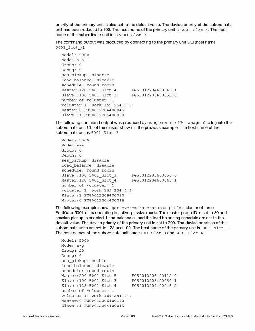
priority of the primary unit is also set to the default value. The device priority of the subordinate unit has been reduced to 100. The host name of the primary unit is 5001_Slot_4. The host name of the subordinate unit in is 5001_Slot_3.
The command output was produced by connecting to the primary unit CLI (host name 5001_Slot_4).
Model: 5000Mode: a-aGroup: 0Debug: 0ses_pickup: disableload_balance: disableschedule: round robinMaster:128 5001_Slot_4 FG50012204400045 1Slave :100 5001_Slot_3 FG50012205400050 0number of vcluster: 1vcluster 1: work 169.254.0.2Master:0 FG50012204400045Slave :1 FG50012205400050
The following command output was produced by using execute HA manage 0 to log into the subordinate unit CLI of the cluster shown in the previous example. The host name of the subordinate unit is 5001_Slot_3.
Model: 5000Mode: a-aGroup: 0Debug: 0ses_pickup: disableload_balance: disableschedule: round robinSlave :100 5001_Slot_3 FG50012205400050 0Master:128 5001_Slot_4 FG50012204400045 1number of vcluster: 1vcluster 1: work 169.254.0.2Slave :1 FG50012205400050Master:0 FG50012204400045
The following example shows get system ha status output for a cluster of three FortiGate-5001 units operating in active-passive mode. The cluster group ID is set to 20 and session pickup is enabled. Load balance all and the load balancing schedule are set to the default value. The device priority of the primary unit is set to 200. The device priorities of the subordinate units are set to 128 and 100. The host name of the primary unit is 5001_Slot_5. The host names of the subordinate units are 5001_Slot_3 and 5001_Slot_4.
Model: 5000Mode: a-pGroup: 20Debug: 0ses_pickup: enableload_balance: disableschedule: round robinMaster:200 5001_Slot_5 FG50012206400112 0Slave :100 5001_Slot_3 FG50012205400050 1Slave :128 5001_Slot_4 FG50012204400045 2number of vcluster: 1vcluster 1: work 169.254.0.1Master:0 FG50012206400112Slave :1 FG50012204400045
Fortinet Technologies Inc. Page 180 FortiOS™ Handbook - High Availability for FortiOS 5.0

Slave :2 FG50012205400050
The following example shows get system ha status output for a cluster of two FortiGate-5001 units with virtual clustering enabled. This command output was produced by logging into the primary unit for virtual cluster 1 (hostname: 5001_Slot_4, serial number FG50012204400045).
The virtual clustering output shows that the cluster unit with host name 5001_Slot_4 and serial number FG50012204400045 is operating as the primary unit for virtual cluster 1 and the subordinate unit for virtual cluster 2.
For virtual cluster 1 the cluster unit that you have logged into is operating in the work state and the serial number of the primary unit for virtual cluster 1 is FG50012204400045. For virtual cluster 2 the cluster unit that you have logged into is operating in the standby state and the serial number of the primary unit for virtual cluster 2 is FG50012205400050.
Model: 5000Mode: a-pGroup: 20Debug: 0ses_pickup: enableload_balance: disableschedule: round robinMaster:128 5001_Slot_4 FG50012204400045 1Slave :100 5001_Slot_3 FG50012205400050 0number of vcluster: 2vcluster 1: work 169.254.0.2Master:0 FG50012204400045Slave :1 FG50012205400050vcluster 2: standby 169.254.0.1Slave :1 FG50012204400045Master:0 FG50012205400050
The following example shows get system ha status output for the same cluster as shown in the previous example after using execute ha manage 0 to log into the primary unit for virtual cluster 2 (hostname: 5001_Slot_3, serial number FG50012205400050).
Model: 5000Mode: a-pGroup: 20Debug: 0ses_pickup: enableload_balance: disableschedule: round robinSlave :100 5001_Slot_3 FG50012205400050 0Master:128 5001_Slot_4 FG50012204400045 1number of vcluster: 2vcluster 1: standby 169.254.0.2Slave :1 FG50012205400050Master:0 FG50012204400045vcluster 2: work 169.254.0.1Master:0 FG50012205400050Slave :1 FG50012204400045
The following example shows get system ha status output for a virtual cluster configuration where the cluster unit with hostname: 5001_Slot_4 and serial number FG50012204400045 is the primary unit for both virtual clusters. This command output is produced by logging into cluster unit with host name 5001_Slot_4 and serial number FG50012204400045.
Model: 5000
Fortinet Technologies Inc. Page 181 FortiOS™ Handbook - High Availability for FortiOS 5.0

Mode: a-pGroup: 20Debug: 0ses_pickup: enableload_balance: disableschedule: round robinMaster:128 5001_Slot_4 FG50012204400045 1Slave :100 5001_Slot_3 FG50012205400050 0number of vcluster: 2vcluster 1: work 169.254.0.2Master:0 FG50012204400045Slave :1 FG50012205400050vcluster 2: work 169.254.0.2Master:0 FG50012204400045Slave :1 FG50012205400050
About the HA cluster index and the execute ha manage command
When a cluster starts up, the FortiGate Cluster Protocol (FGCP) assigns a cluster index and a HA heartbeat IP address to each cluster unit based on the serial number of the cluster unit. The FGCP selects the cluster unit with the highest serial number to become the primary unit. The FGCP assigns a cluster index of 0 and an HA heartbeat IP address of 169.254.0.1 to this unit. The FGCP assigns a cluster index of 1 and an HA heartbeat IP address of 169.254.0.2 to the cluster unit with the second highest serial number. If the cluster contains more units, the cluster unit with the third highest serial number is assigned a cluster index of 2 and an HA heartbeat IP address of 169.254.0.3, and so on. You can display the cluster index assigned to each cluster unit using the get system ha status command. Also when you use the execute ha manage command you select a cluster unit to log into by entering its cluster index.
The cluster index and HA heartbeat IP address only change if a unit leaves the cluster or if a new unit joins the cluster. When one of these events happens, the FGCP resets the cluster index and HA heartbeat IP address of each cluster unit according to serial number in the same way as when the cluster first starts up.
Each cluster unit keeps its assigned cluster index and HA heartbeat IP address even as the units take on different roles in the cluster. After the initial cluster index and HA heartbeat IP addresses are set according to serial number, the FGCP checks other primary unit selection criteria such as device priority and monitored interfaces. Checking these criteria could result in selecting a cluster unit without the highest serial number to operate as the primary unit.
Even if the cluster unit without the highest serial number now becomes the primary unit, the cluster indexes and HA heartbeat IP addresses assigned to the individual cluster units do not change. Instead the FGCP assigns a second cluster index, which could be called the operating cluster index, to reflect this role change. The operating cluster index is 0 for the primary unit and 1 and higher for the other units in the cluster. By default both sets of cluster indexes are the same. But if primary unit selection selects the cluster unit that does not have the highest serial number to be the primary unit then this cluster unit is assigned an operating cluster index of 0. The operating cluster index is used by the FGCP only. You can display the operating cluster index assigned to each cluster unit using the get system ha status command. There are no CLI commands that reference the operating cluster index.
Even though there are two cluster indexes there is only one HA heartbeat IP address and the HA heartbeat address is not affected by a change in the operating cluster index.
Fortinet Technologies Inc. Page 182 FortiOS™ Handbook - High Availability for FortiOS 5.0

Using the execute ha manage command
When you use the CLI command execute ha manage <index_integer> to connect to the CLI of another cluster unit, the <index_integer> that you enter is the cluster index of the unit that you want to connect to.
Using get system ha status to display cluster indexes
You can display the cluster index assigned to each cluster unit using the CLI command get system ha status. The following example shows the information displayed by the get system ha status command for a cluster consisting of two FortiGate-5001SX units operating in active-passive HA mode with virtual domains not enabled and without virtual clustering.
get system ha statusModel: 5000Mode: a-pGroup: 0Debug: 0ses_pickup: disableMaster:128 5001_slot_7 FG50012205400050 0Slave :128 5001_slot_11 FG50012204400045 1number of vcluster: 1vcluster 1: work 169.254.0.1Master:0 FG50012205400050Slave :1 FG50012204400045
In this example, the cluster unit with serial number FG50012205400050 has the highest serial number and so has a cluster index of 0 and the cluster unit with serial number FG50012204400045 has a cluster index of 1. From the CLI of the primary (or master) unit of this cluster you can connect to the CLI of the subordinate (or slave) unit using the following command:
execute ha manage 1
This works because the cluster unit with serial number FG50012204400045 has a cluster index of 1.
The get system ha status command output shows two similar lists of indexes and serial numbers. The listing on the sixth and seventh lines of the command output are the cluster indexes assigned according to cluster unit serial number. These are the cluster indexes that you enter when using the execute ha manage command. The cluster indexes shown in the last two lines of the command output are the operating cluster indexes that reflect how the cluster units are actually operating in the cluster. In this example both sets of cluster indexes are the same.
The last three lines of the command output display the status of vcluster 1. In a cluster consisting of two cluster units operating without virtual domains enabled all clustering actually takes place in virtual cluster 1. HA is designed to work this way to support virtual clustering. If this cluster was operating with virtual domains enabled, adding virtual cluster 2 is similar to adding a new copy of virtual cluster 1. Virtual cluster 2 is visible in the get system ha status command output when you add virtual domains to virtual cluster 2.
The HA heartbeat IP address displayed on line 8 is the HA heartbeat IP address of the cluster unit that is actually operating as the primary unit. For a default configuration this IP address will always be 169.254.0.1 because the cluster unit with the highest serial number will be the primary unit. This IP address changes if the operating primary unit is not the primary unit with the highest serial number.
Fortinet Technologies Inc. Page 183 FortiOS™ Handbook - High Availability for FortiOS 5.0
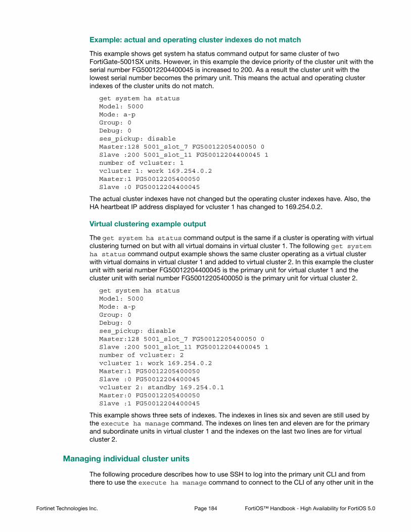
Example: actual and operating cluster indexes do not match
This example shows get system ha status command output for same cluster of two FortiGate-5001SX units. However, in this example the device priority of the cluster unit with the serial number FG50012204400045 is increased to 200. As a result the cluster unit with the lowest serial number becomes the primary unit. This means the actual and operating cluster indexes of the cluster units do not match.
get system ha statusModel: 5000Mode: a-pGroup: 0Debug: 0ses_pickup: disableMaster:128 5001_slot_7 FG50012205400050 0Slave :200 5001_slot_11 FG50012204400045 1number of vcluster: 1vcluster 1: work 169.254.0.2Master:1 FG50012205400050Slave :0 FG50012204400045
The actual cluster indexes have not changed but the operating cluster indexes have. Also, the HA heartbeat IP address displayed for vcluster 1 has changed to 169.254.0.2.
Virtual clustering example output
The get system ha status command output is the same if a cluster is operating with virtual clustering turned on but with all virtual domains in virtual cluster 1. The following get system ha status command output example shows the same cluster operating as a virtual cluster with virtual domains in virtual cluster 1 and added to virtual cluster 2. In this example the cluster unit with serial number FG50012204400045 is the primary unit for virtual cluster 1 and the cluster unit with serial number FG50012205400050 is the primary unit for virtual cluster 2.
get system ha statusModel: 5000Mode: a-pGroup: 0Debug: 0ses_pickup: disableMaster:128 5001_slot_7 FG50012205400050 0Slave :200 5001_slot_11 FG50012204400045 1number of vcluster: 2vcluster 1: work 169.254.0.2Master:1 FG50012205400050Slave :0 FG50012204400045vcluster 2: standby 169.254.0.1Master:0 FG50012205400050Slave :1 FG50012204400045
This example shows three sets of indexes. The indexes in lines six and seven are still used by the execute ha manage command. The indexes on lines ten and eleven are for the primary and subordinate units in virtual cluster 1 and the indexes on the last two lines are for virtual cluster 2.
Managing individual cluster units
The following procedure describes how to use SSH to log into the primary unit CLI and from there to use the execute ha manage command to connect to the CLI of any other unit in the
Fortinet Technologies Inc. Page 184 FortiOS™ Handbook - High Availability for FortiOS 5.0

cluster. The procedure is very similar if you use telnet, or the web-based manager dashboard CLI console.
You can use the execute ha manage command from the CLI of any cluster unit to log into the CLI of another the cluster unit. Usually you would use this command from the CLI of the primary unit to log into the CLI of a subordinate unit. However, if you have logged into a subordinate unit CLI, you can use this command to log into the primary unit CLI, or the CLI of another subordinate unit.
Using SSH or telnet or the web-based manager dashboard CLI console you can only log into the primary unit CLI. Using a direct console connection you can log into any cluster unit. In both cases you can use execute ha manage to connect to the CLI of other cluster units.
1. Use SSH to connect to the cluster and log into the primary unit CLI.
Connect to any cluster interface configured for SSH administrative access to log into the cluster.
2. Enter the following command followed by a space and type a question mark (?):
execute ha manage
The CLI displays a list of all the subordinate units in the cluster. Each cluster unit is numbered, starting at 1. The information displayed for each cluster unit includes the unit serial number and the host name of the unit.
3. Complete the command with the number of the subordinate unit to log into. For example, to log into subordinate unit 1, enter the following command:
execute ha manage 1
Press Enter to connect to and log into the CLI of the selected subordinate unit. If this subordinate unit has a different host name, the CLI prompt changes to this host name.
You can use CLI commands to manage this subordinate unit. If you make changes to the configuration of any cluster unit (primary or subordinate unit) these changes are synchronized to all cluster units.
4. You can now use the execute ha manage command to connect to any other cluster unit (including the primary unit). You can also use the exit command to return to the primary unit CLI.
Disconnecting a cluster unit from a cluster
Use the following procedures to disconnect a cluster unit from a functioning cluster without disrupting the operation of the cluster. You can disconnect a cluster unit if you need to use the disconnected FortiGate unit for another purpose, such as to act as a standalone firewall.
You can use the following procedures for a standard cluster and for a virtual clustering configuration. To use the following procedures from a virtual cluster you must be logged in as the admin administrator and you must have selected Global Configuration.
When you disconnect a cluster unit you must assign an IP address and netmask to one of the interfaces of the disconnected unit. You can disconnect any unit from the cluster even the primary unit. After the unit is disconnected, the cluster responds as if the disconnected unit has failed. The cluster may renegotiate and may select a new primary unit.
You log into the subordinate unit using the FGT_ha_admin administrator account. This built-in administrator account gives you read and write permission on the subordinate unit. Normally this built-in administrative account is not visible, however FGT_ha_admin does appear in event log messages.
Fortinet Technologies Inc. Page 185 FortiOS™ Handbook - High Availability for FortiOS 5.0
When the cluster unit is disconnected the HA mode is changed to standalone. In addition, all interface IP addresses of the disconnected unit are set to 0.0.0.0 except for the interface that you configure.
Otherwise the configuration of the disconnected unit is not changed. The HA configuration of the disconnected unit is not changed either (except to change the HA mode to Standalone).
To disconnect a cluster unit from a cluster - web-based manager
1. Go to System > Config > HA to view the cluster members list.
2. Select the Disconnect from cluster icon for the cluster unit to disconnect from the cluster.
3. Select the interface that you want to configure. You also specify the IP address and netmask for this interface. When the FortiGate unit is disconnected, all management access options are enabled for this interface.
4. Specify an IP address and netmask for the interface. You can use this IP address to connect to the interface to configure the disconnected FortiGate unit.
5. Select OK.
The FortiGate unit is disconnected from the cluster and the cluster may renegotiate and select a new primary unit. The selected interface of the disconnected unit is configured with the specified IP address and netmask.
To disconnect a cluster unit from a cluster - CLI
1. Enter the following command to disconnect a cluster unit with serial number FGT5002803033050. The internal interface of the disconnected unit is set to IP address 1.1.1.1 and netmask 255.255.255.0.
execute ha disconnect FGT5002803033050 internal 1.1.1.1 255.255.255.0
Adding a disconnected FortiGate unit back to its cluster
If you disconnect a FortiGate unit from a cluster, you can re-connect the disconnected FortiGate unit to the cluster by setting the HA mode of the disconnected unit to match the HA mode of the cluster. Usually the disconnected unit rejoins the cluster as a subordinate unit and the cluster automatically synchronizes its configuration.
The following procedure assumes that the disconnected FortiGate unit is correctly physically connected to your network and to the cluster but is not running in HA mode and not part of the cluster.
Before you start this procedure you should note the device priority of the primary unit.
You do not have to change the HA password on the disconnected unit unless the HA password has been changed after the unit was disconnected. Disconnecting a unit from a cluster does not change the HA password.
You should make sure that the device priority of the disconnected unit is lower than the device priority of the current primary unit. You should also make sure that the HA override CLI option is not enabled on the disconnected unit. Otherwise, when the disconnected unit joins the cluster, the cluster will renegotiate and the disconnected unit may become the primary unit. If this happens, the configuration of the disconnected unit is synchronized to all other cluster units. This configuration change might disrupt the operation of the cluster.
Fortinet Technologies Inc. Page 186 FortiOS™ Handbook - High Availability for FortiOS 5.0

To add a disconnected FortiGate unit back to its cluster - web-based manager
1. Log into the disconnected FortiGate unit.
If virtual domains are enabled, log in as the admin administrator and select Global Configuration.
2. Go to System > Config > HA.
3. Change Mode to match the mode of the cluster.
4. If required, change the group name and password to match the cluster.
5. Set the Device Priority lower than the device priority of the primary unit.
6. Select OK.
The disconnected FortiGate unit joins the cluster.
To add a disconnected FortiGate unit back to its cluster - CLI
1. Log into the CLI of the FortiGate unit to be added back to the cluster.
2. Enter the following command to access the global configuration and add the FortiGate unit back to a cluster operating in active-passive mode and set the device priority to 50 (a low number) so that this unit will not become the primary unit:config global
config system ha
set mode a-p
set priority 50
end
end
You may have to also change the group name, group id and password. However if you have not changed these for the cluster or the FortiGate unit after it was disconnected from the cluster you should not have to adjust them now.
HA diagnose commands
You can use the following diagnose command to display a data about a cluster:
diagnose sys ha dump-by {all-xdb | all-vcluster| rcache | all-group |
memory | debug-zone | vdom | kernel | device | stat| sesync}
The example out put below is from a cluster of two FortiGate-5001Cs. In this cluster the base1 and base2 interfaces communicate the HA heartbeat and port monitoring has been added to poort1.
Fortinet Technologies Inc. Page 187 FortiOS™ Handbook - High Availability for FortiOS 5.0

all-xdb
This command displays information about the current configuration of the cluster and how its operating. You can use the out to determine the primary unit, the state of port monitoring as well as most cluster configuration details and status.
diagnose sys ha dump-by all-xdb
HA information.
idx=1,nxentry=2,linkfails=7,flags=0,digest=7.72.e3.2e.8e.d1...
xentry FG-5KC3E13800046 nhbdev=2,nventry=0, hops=0.
base1, 50, mac=0.9.f,bc.e.6c, neighbor=1.
id=FG-5KC3E13800084, mac=0.9.f,bc.11.18.
base2, 50, mac=0.9.f,bc.e.71, neighbor=1.
id=FG-5KC3E13800084, mac=0.9.f,bc.11.1d.
xentry FG-5KC3E13800084 nhbdev=2,nventry=1, hops=1.
base1, 50, mac=0.9.f,bc.11.18, neighbor=1.
id=FG-5KC3E13800046, mac=0.9.f,bc.e.6c.
base2, 50, mac=0.9.f,bc.11.1d, neighbor=1.
id=FG-5KC3E13800046, mac=0.9.f,bc.e.71.
npath=1,FG-5KC3E13800084
ventry idx=0,id=1,FG-5KC3E13800084,prio=128,0,claimed=0,override=0,flag=0,time=12974,mon=0
mondev=port1,50
idx=0,nxentry=2,linkfails=7,flags=3,digest=7.95.b.9.a8.5d...
xentry FG-5KC3E13800084 nhbdev=2,nventry=1, hops=0.
base1, 50, mac=0.9.f,bc.11.18, neighbor=1.
id=FG-5KC3E13800046, mac=0.9.f,bc.e.6c.
base2, 50, mac=0.9.f,bc.11.1d, neighbor=1.
id=FG-5KC3E13800046, mac=0.9.f,bc.e.71.
ventry idx=0,id=1,FG-5KC3E13800084,prio=128,0,claimed=0,override=0,flag=0,time=12974,mon=0
mondev=port1,50
xentry FG-5KC3E13800046 nhbdev=2,nventry=1, hops=1.
base1, 50, mac=0.9.f,bc.e.6c, neighbor=1.
id=FG-5KC3E13800084, mac=0.9.f,bc.11.18.
base2, 50, mac=0.9.f,bc.e.71, neighbor=1.
id=FG-5KC3E13800084, mac=0.9.f,bc.11.1d.
npath=1,FG-5KC3E13800046
ventry idx=0,id=1,FG-5KC3E13800046,prio=128,0,claimed=0,override=0,flag=0,time=2,mon=0
mondev=port1,50
Fortinet Technologies Inc. Page 188 FortiOS™ Handbook - High Availability for FortiOS 5.0

all-vcluster
This command displays the status and configuration of the individual cluster units. You can use the output of this command to determine the primary unit and the status of each cluster unit.
diagnose sys ha dump-by all-vcluster
HA information.
vcluster id=1, nventry=2, state=work, digest=5.f8.d1.63.4d.d2...
ventry idx=0,id=1,FG-5KC3E13800046,prio=128,0,claimed=0,override=0,flag=1,time=0,mon=0
mondev=port1,50
ventry idx=1,id=1,FG-5KC3E13800084,prio=128,0,claimed=0,override=0,flag=0,time=12974,mon=0
stat
This command displays some statistics about how well the cluster is functioning. Information includes packet counts, memory use, failed links and ping failures.
diagnose sys ha dump-by stat
HA information.
packet count = 1, memory = 220.
check_linkfails = 0, linkfails = 0, check_pingsvrfails = 2822
bufcnt = -5, bufmem = 0
Fortinet Technologies Inc. Page 189 FortiOS™ Handbook - High Availability for FortiOS 5.0

HA and failover protection
In FortiGate active-passive HA, the FortiGate Clustering Protocol (FGCP) provides failover protection. This means that an active-passive cluster can provide FortiGate services even when one of the cluster units encounters a problem that would result in complete loss of connectivity for a stand-aloneFortiGate unit. This failover protection provides a backup mechanism that can be used to reduce the risk of unexpected downtime, especially in a mission-critical environment.
The FGCP supports three kinds of failover protection. Device failover automatically replaces a failed device and restarts traffic flow with minimal impact on the network. Link failover maintains traffic flow if a link fails. Session failover resumes communication sessions with minimal loss of data if a device or link failover occurs.
This chapter describes how FGCP failover protection works and provides detailed NAT/Route and Transparent mode packet flow descriptions.
This chapter contains the following sections:
• About active-passive failover
• About active-active failover
• Device failover
• HA heartbeat and communication between cluster units
• Cluster virtual MAC addresses
• Synchronizing the configuration
• Synchronizing kernel routing tables
• Synchronizing IPsec VPN SAs
• Link failover (port monitoring or interface monitoring)
• Subsecond failover
• Remote link failover
• Session failover (session pick-up)
• WAN optimization and HA
• Failover and attached network equipment
• Monitoring cluster units for failover
• NAT/Route mode active-passive cluster packet flow
• Transparent mode active-passive cluster packet flow
• Failover performance
About active-passive failover
To achieve failover protection in an active-passive cluster, one of the cluster units functions as the primary unit, while the rest of the cluster units are subordinate units, operating in an active stand-by mode. The cluster IP addresses and HA virtual MAC addresses are associated with the cluster interfaces of the primary unit. All traffic directed at the cluster is actually sent to and processed by the primary unit.
While the cluster is functioning, the primary unit functions as the FortiGate network security device for the networks that it is connected to. In addition, the primary unit and subordinate
Page 190

units use the HA heartbeat to keep in constant communication. The subordinate units report their status to the cluster unit and receive and store connection and state table updates.
Device failure
If the primary unit encounters a problem that is severe enough to cause it to fail, the remaining cluster units negotiate to select a new primary unit. This occurs because all of the subordinate units are constantly waiting to negotiate to become primary units. Only the heartbeat packets sent by the primary unit keep the subordinate units from becoming primary units. Each received heartbeat packet resets negotiation timers in the subordinate units. If this timer is allowed to run out because the subordinate units do not receive heartbeat packets from the primary unit, the subordinate units assume that the primary unit has failed, and negotiate to become primary units themselves.
Using the same FGCP negotiation process that occurs when the cluster starts up, after they determine that the primary unit has failed, the subordinate units negotiate amongst themselves to select a new primary unit. The subordinate unit that wins the negotiation becomes the new primary unit with the same MAC and IP addresses as the former primary unit. The new primary unit then sends gratuitous ARP packets out all of its interfaces to inform attached switches to send traffic to the new primary unit. Sessions then resume with the new primary unit.
Link failure
If a primary unit interface fails or is disconnected while a cluster is operation, a link failure occurs. When a link failure occurs the cluster units negotiate to select a new primary unit. Since the primary unit has not stopped operating, it participates in the negotiation. The link failure means that a new primary unit must be selected and the cluster unit with the link failure joins the cluster as a subordinate unit.
Just as for a device failover, the new primary unit sends gratuitous arp packets out all of its interfaces to inform attached switches to send traffic to it. Sessions then resume with the new primary unit.
If a subordinate unit experiences a device failure its status in the cluster does not change. However, in future negotiations a cluster unit with a link failure is unlikely to become the primary unit.
Session failover
If you enable session failover (also called session pickup) for the cluster, during cluster operation the primary unit informs the subordinate units of changes to the primary unit connection and state tables, keeping the subordinate units up-to-date with the traffic currently being processed by the cluster.
After a failover the new primary unit recognizes open sessions that were being handled by the cluster. The sessions continue to be processed by the new primary unit and are handled according to their last known state.
If you leave session pickup disabled, the cluster does not keep track of sessions and after a failover, active sessions have to be restarted or resumed.
Primary unit recovery
If a primary unit recovers after a device or link failure, it will operate as a subordinate unit, unless the override CLI keyword is enabled and its device priority is set higher than the unit priority of other cluster units (see “HA override” on page 38).
Fortinet Technologies Inc. Page 191 FortiOS™ Handbook - High Availability for FortiOS 5.0

About active-active failover
HA failover in a cluster running in active-active mode is similar to active-passive failover described above. Active-active subordinate units are constantly waiting to negotiate to become primary units and, if session failover is enabled, continuously receive connection state information from the primary unit. If the primary unit fails, or one of the primary unit interfaces fails, the cluster units use the same mechanisms to detect the failure and to negotiate to select a new primary unit. If session failover is enabled, the new primary unit also maintains communication sessions through the cluster using the shared connection state table.
Active-active HA load balances sessions among all cluster units. For session failover, the cluster must maintain all of these sessions. To load balance sessions, the functioning cluster uses a load balancing schedule to distribute sessions to all cluster units. The shared connection state table tracks the communication sessions being processed by all cluster units (not just the primary unit). After a failover, the new primary unit uses the load balancing schedule to re-distribute all of the communication sessions recorded in the shared connection state table among all of the remaining cluster units. The connections continue to be processed by the cluster, but possibly by a different cluster unit, and are handled according to their last known state.
Device failover
The FGCP provides transparent device failover. Device failover is a basic requirement of any highly available system. Device failover means that if a device fails, a replacement device automatically takes the place of the failed device and continues operating in the same manner as the failed device.
In the case of FortiOS HA, the device is the primary unit. If the primary unit fails, device failover ensures that one of the subordinate units in the cluster automatically takes the place of the primary unit and can continue processing network traffic in the same way as the failed primary unit.
FortiGate HA device failover is supported by the HA heartbeat, virtual MAC addresses, configuration synchronization, route synchronization and IPsec VPN SA synchronization.
The HA heartbeat makes sure that the subordinate units detect a primary unit failure. If the primary unit fails to respond on time to HA heartbeat packets the subordinate units assume that the primary unit has failed and negotiate to select a new primary unit.
The new primary unit takes the place of the failed primary unit and continues functioning in the same way as the failed primary unit. For the new primary unit to continue functioning like the failed primary unit, the new primary unit must be able to reconnect to network devices and the new primary unit must have the same configuration as the failed primary unit.
FortiGate HA uses virtual MAC addresses to reconnect the new primary unit to network devices. The FGCP causes the new primary unit interfaces to acquire the same virtual MAC addresses as the failed primary unit. As a result, the new primary unit has the same network identity as the failed primary unit.
The new primary unit interfaces have different physical connections than the failed primary unit. Both the failed and the new primary unit interfaces are connected to the same switches, but the new primary unit interfaces are connected to different ports on these switches. To make sure
Device failover does not maintain communication sessions. After a device failover, communication sessions have to be restarted. To maintain communication sessions, you must enable session failover. See “Session failover (session pick-up)” on page 231.
Fortinet Technologies Inc. Page 192 FortiOS™ Handbook - High Availability for FortiOS 5.0

that the switches send packets to the new primary unit, the new primary unit interfaces send gratuitous ARP packets to the connected switches. These gratuitous ARP packets notify the switches that the primary unit MAC and IP addresses are on different switch ports and cause the switches to send packets to the ports connected to the new primary unit. In this way, the new primary unit continues to receive packets that would otherwise have been sent to the failed primary unit.
Configuration synchronization means that the new primary unit always has the same configuration as the failed primary unit. As a result the new primary unit operates in exactly the same way as the failed primary unit. If configuration synchronization were not available the new primary unit may not process network traffic in the same way as the failed primary unit.
Route synchronization synchronizes the primary unit routing table to all subordinate units so that after a failover the new primary unit does not have to form a completely new routing table. IPsec VPN SA synchronization synchronizes IPsec VPN security associations (SAs) and other IPsec session data so that after a failover the new primary unit can resume IPsec tunnels without having to establish new SAs.
HA heartbeat and communication between cluster units
The HA heartbeat keeps cluster units communicating with each other. The heartbeat consists of hello packets that are sent at regular intervals by the heartbeat interface of all cluster units. These hello packets describe the state of the cluster unit and are used by other cluster units to keep all cluster units synchronized.
HA heartbeat packets are non-TCP packets that use Ethertype values 0x8890, 0x8891, and 0x8890. The default time interval between HA heartbeats is 200 ms. The FGCP uses link-local IP4 addresses in the 169.254.0.x range for HA heartbeat interface IP addresses.
For best results, isolate the heartbeat devices from your user networks by connecting the heartbeat devices to a separate switch that is not connected to any network. If the cluster consists of two FortiGate units you can connect the heartbeat device interfaces directly using a crossover cable. Heartbeat packets contain sensitive information about the cluster configuration. Heartbeat packets may also use a considerable amount of network bandwidth. For these reasons, it is preferable to isolate heartbeat packets from your user networks.
On startup, a FortiGate unit configured for HA operation broadcasts HA heartbeat hello packets from its HA heartbeat interface to find other FortiGate units configured to operate in HA mode. If two or more FortiGate units operating in HA mode connect with each other, they compare HA configurations (HA mode, HA password, and HA group ID). If the HA configurations match, the units negotiate to form a cluster.
While the cluster is operating, the HA heartbeat confirms that all cluster units are functioning normally. The heartbeat also reports the state of all cluster units, including the communication sessions that they are processing.
Heartbeat interfaces
A heartbeat interface is an Ethernet network interface in a cluster that is used by the FGCP for HA heartbeat communications between cluster units.
Fortinet Technologies Inc. Page 193 FortiOS™ Handbook - High Availability for FortiOS 5.0

To change the HA heartbeat configuration go to System > Config > HA and select the FortiGate interfaces to use as HA heartbeat interfaces.
From the CLI enter the following command to make port4 and port5 HA heartbeat interfaces and give both interfaces a heartbeat priority of 150:
config system ha
set hbdev port4 150 port5 150
end
The following example shows how to change the default heartbeat interface configuration so that the port4 and port1 interfaces can be used for HA heartbeat communication and to give the port4 interface the highest heartbeat priority so that port4 is the preferred HA heartbeat interface.
config system ha
set hbdev port4 100 port1 50
end
By default, for most FortiGate models two interfaces are configured to be heartbeat interfaces. You can change the heartbeat interface configuration as required. For example you can select additional or different heartbeat interfaces. You can also select only one heartbeat interface.
In addition to selecting the heartbeat interfaces, you also set the Priority for each heartbeat interface. In all cases, the heartbeat interface with the highest priority is used for all HA heartbeat communication. If the interface fails or becomes disconnected, the selected heartbeat interface that has the next highest priority handles all heartbeat communication.
If more than one heartbeat interface has the same priority, the heartbeat interface with the highest priority that is also highest in the heartbeat interface list is used for all HA heartbeat communication. If this interface fails or becomes disconnected, the selected heartbeat interface with the highest priority that is next highest in the list handles all heartbeat communication.
The default heartbeat interface configuration sets the priority of two heartbeat interfaces to 50. You can accept the default heartbeat interface configuration if one or both of the default heartbeat interfaces are connected. You can select different heartbeat interfaces, select more heartbeat interfaces and change heartbeat priorities according to your requirements.
For the HA cluster to function correctly, you must select at least one heartbeat interface and this interface of all of the cluster units must be connected together. If heartbeat communication is interrupted and cannot failover to a second heartbeat interface, the cluster units will not be able to communicate with each other and more than one cluster unit may become a primary unit. As a result the cluster stops functioning normally because multiple devices on the network may be operating as primary units with the same IP and MAC addresses creating a kind if split brain scenario.
The heartbeat interface priority range is 0 to 512. The default priority when you select a new heartbeat interface is 0. The higher the number the higher the priority.
In most cases you can maintain the default heartbeat interface configuration as long as you can connect the heartbeat interfaces together. Configuring HA heartbeat interfaces is the same for virtual clustering and for standard HA clustering.
You can enable heartbeat communications for physical interfaces, but not for VLAN subinterfaces, IPsec VPN interfaces, redundant interfaces, or for 802.3ad aggregate interfaces. You cannot select these types of interfaces in the heartbeat interface list.
Do not use a switch port for the HA heartbeat traffic. This configuration is not supported.
Fortinet Technologies Inc. Page 194 FortiOS™ Handbook - High Availability for FortiOS 5.0

Selecting more heartbeat interfaces increases reliability. If a heartbeat interface fails or is disconnected, the HA heartbeat fails over to the next heartbeat interface.
You can select up to 8 heartbeat interfaces. This limit only applies to FortiGate units with more than 8 physical interfaces.
HA heartbeat traffic can use a considerable amount of network bandwidth. If possible, enable HA heartbeat traffic on interfaces used only for HA heartbeat traffic or on interfaces connected to less busy networks.
Connecting HA heartbeat interfaces
For most FortiGate models if you do not change the heartbeat interface configuration, you can isolate the default heartbeat interfaces of all of the cluster units by connecting them all to the same switch. Use one switch per heartbeat interface. If the cluster consists of two units you can connect the heartbeat interfaces together using crossover cables. For an example of how to connect heartbeat interfaces, see “Connecting a FortiGate HA cluster” on page 27.
HA heartbeat and data traffic are supported on the same cluster interface. In NAT/Route mode, if you decide to use heartbeat interfaces for processing network traffic or for a management connection, you can assign the interface any IP address. This IP address does not affect HA heartbeat traffic.
In Transparent mode, you can connect the heartbeat interface to your network and enable management access. You would then establish a management connection to the interface using the Transparent mode management IP address. This configuration does not affect HA heartbeat traffic.
Heartbeat packets and heartbeat interface selection
HA heartbeat hello packets are constantly sent by all of the enabled heartbeat interfaces. Using these hello packets, each cluster unit confirms that the other cluster units are still operating. The FGCP selects one of the heartbeat interfaces to be used for communication between the cluster units. The FGCP selects the heartbeat interface for heartbeat communication based on the linkfail states of the heartbeat interfaces, on the priority of the heartbeat interfaces, and on the interface index.
The FGCP checks the linkfail state of all heartbeat interfaces to determine which ones are connected. The FGCP selects one of these connected heartbeat interfaces to be the one used for heartbeat communication. The FGCP selects the connected heartbeat interface with the highest priority for heartbeat communication.
If more than one connected heartbeat interface has the highest priority the FGCP selects the heartbeat interface with the lowest interface index. The web-based manager lists the FortiGate unit interfaces in alphabetical order. This order corresponds to the interface index order with lowest index at the top and highest at the bottom. If more than one heartbeat interface has the highest priority, the FGCP selects the interface that is highest in the heartbeat interface list (or first in alphabetical order) for heartbeat communication.
If the interface that is processing heartbeat traffic fails or becomes disconnected, the FGCP uses the same criteria to select another heartbeat interface for heartbeat communication. If the original heartbeat interface is fixed or reconnected, the FGCP again selects this interface for heartbeat communication.
The HA heartbeat communicates cluster session information, synchronizes the cluster configuration, synchronizes the cluster routing table, and reports individual cluster member status. The HA heartbeat constantly communicates HA status information to make sure that the cluster is operating properly.
Fortinet Technologies Inc. Page 195 FortiOS™ Handbook - High Availability for FortiOS 5.0

Interface index and display order
The web-based manager and CLI display interface names in alphanumeric order. For example, the sort order for a FortiGate unit with 10 interfaces (named port1 through port10) places port10 at the bottom of the list:
• port1
• port2 through 9
• port10
However, interfaces are indexed in hash map order, rather than purely by alphabetic order or purely by interface number value comparisons. As a result, the list is sorted primarily alphabetical by interface name (for example, base1 is before port1), then secondarily by index numbers:
• port1
• port10
• port2 through port9
HA heartbeat interface IP addresses
The FGCP uses link-local IP4 addresses (RFC 3927) in the 169.254.0.x range for HA heartbeat interface IP addresses and for inter-VDOM link interface IP addresses. When a cluster initially starts up, the primary unit heartbeat interface IP address is 169.254.0.1. Subordinate units are assigned heartbeat interface IP addresses in the range 169.254.0.2 to 169.254.0.63. HA inter-VDOM link interfaces on the primary unit are assigned IP addresses 169.254.0.65 and 169.254.0.66.
The ninth line of the following CLI command output shows the HA heartbeat interface IP address of the primary unit.
get system ha status
Model: 620
Mode: a-p
Group: 0
Debug: 0
ses_pickup: disable
Master:150 head_office_upper FG600B3908600825 1
Slave :150 head_office_lower FG600B3908600705 0
number of vcluster: 1
vcluster 1: work 169.254.0.1
Master:0 FG600B3908600825
Slave :1 FG600B3908600705
You can also use the execute traceroute command from the subordinate unit CLI to display HA heartbeat IP addresses and the HA inter-VDOM link IP addresses. For example, use execute ha manage 1 to connect to the subordinate unit CLI and then enter the following command to trace the route to an IP address on your network:
execute traceroute 172.20.20.10traceroute to 172.20.20.10 (172.20.20.10), 32 hops max, 72 byte packets1 169.254.0.1 0 ms 0 ms 0 ms2 169.254.0.66 0 ms 0 ms 0 ms3 172.20.20.10 0 ms 0 ms 0 ms
Fortinet Technologies Inc. Page 196 FortiOS™ Handbook - High Availability for FortiOS 5.0

Both HA heartbeat and data traffic are supported on the same FortiGate interface. All heartbeat communication takes place on a separate VDOM called vsys_ha. Heartbeat traffic uses a virtual interface called port_ha in the vsys_ha VDOM. Data and heartbeat traffic use the same physical interface, but they’re logically separated into separate VDOMs.
Heartbeat packet Ethertypes
Normal IP packets are 802.3 packets that have an Ethernet type (Ethertype) field value of 0x0800. Ethertype values other than 0x0800 are understood as level2 frames rather than IP packets.
By default, HA heartbeat packets use the following Ethertypes:
• HA heartbeat packets for NAT/Route mode clusters use Ethertype 0x8890. These packets are used by cluster units to find other cluster units and to verify the status of other cluster units while the cluster is operating. You can change the Ethertype of these packets using the ha-eth-type option of the config system ha command.
• HA heartbeat packets for Transparent mode clusters use Ethertype 0x8891. These packets are used by cluster units to find other cluster units and to verify the status of other cluster units while the cluster is operating. You can change the Ethertype of these packets using the hc-eth-type option of the config system ha command.
• HA telnet sessions between cluster units over HA heartbeat links use Ethertype 0x8893. The telnet sessions are used to synchronize the cluster configurations. Telnet sessions are also used when an administrator uses the execute ha manage command to connect from one cluster unit CLI to another. You can change the Ethertype of these packets using the l2ep-eth-type option of the config system ha command.
Because heartbeat packets are recognized as level2 frames, the switches and routers on your heartbeat network that connect to heartbeat interfaces must be configured to allow them. If level2 frames are dropped by these network devices, heartbeat traffic will not be allowed between the cluster units.
Some third-party network equipment may use packets with these Ethertypes for other purposes. For example, Cisco N5K/Nexus switches use Ethertype 0x8890 for some functions. When one of these switches receives Ethertype 0x8890 packets from an attached cluster unit, the switch generates CRC errors and the packets are not forwarded. As a result, FortiGate units connected with these switches cannot form a cluster.
In some cases, if the heartbeat interfaces are connected and configured so regular traffic flows but heartbeat traffic is not forwarded, you can change the configuration of the switch that connects the HA heartbeat interfaces to allow level2 frames with Ethertypes 0x8890, 0x8893, and 0x8891 to pass.
Alternatively, you can use the following CLI options to change the Ethertypes of the HA heartbeat packets:
config system ha
set ha-eth-type <ha_ethertype_4-digit_hex
set hc-eth-type <hc_ethertype_4-digit_ex>
set l2ep-eth-type <l2ep_ethertype_4-digit_hex>
end
Fortinet Technologies Inc. Page 197 FortiOS™ Handbook - High Availability for FortiOS 5.0

For example, use the following command to change the Ethertype of the HA heartbeat packets from 0x8890 to 0x8895 and to change the Ethertype of HA Telnet session packets from 0x8891 to 0x889f:
config system ha
set ha-eth-type 8895
set l2ep-eth-type 889f
end
Modifying heartbeat timing
In an HA cluster, if a cluster unit CPU becomes very busy, the cluster unit may not be able to send heartbeat packets on time. If heartbeat packets are not sent on time other units in the cluster may think that the cluster unit has failed and the cluster will experience a failover.
A cluster unit CPU may become very busy if the cluster is subject to a syn flood attack, if network traffic is very heavy, or for other similar reasons. You can use the following CLI commands to configure how the cluster times HA heartbeat packets:
config system ha
set hb-interval <interval_integer>
set hb-lost-threshold <threshold_integer>
set helo-holddown <holddown_integer>
end
Changing the lost heartbeat threshold
The lost heartbeat threshold is the number of consecutive heartbeat packets that are not received from another cluster unit before assuming that the cluster unit has failed. The default value is 6, meaning that if the 6 heartbeat packets are not received from a cluster unit then that cluster unit is considered to have failed. The range is 1 to 60 packets.
If the primary unit does not receive a heartbeat packet from a subordinate unit before the heartbeat threshold expires, the primary unit assumes that the subordinate unit has failed.
If a subordinate unit does not receive a heartbeat packet from the primary unit before the heartbeat threshold expires, the subordinate unit assumes that the primary unit has failed. The subordinate unit then begins negotiating to become the new primary unit.
The lower the hb-lost-threshold the faster a cluster responds when a unit fails. However, sometimes heartbeat packets may not be sent because a cluster unit is very busy. This can lead to a false positive failure detection. To reduce these false positives you can increase the hb-lost-threshold.
Use the following CLI command to increase the lost heartbeat threshold to 12:
config system ha
set hb-lost-threshold 12
end
Changing the heartbeat interval
The heartbeat interval is the time between sending HA heartbeat packets. The heartbeat interval range is 1 to 20 (100*ms). The heartbeat interval default is 2 (200 ms).
A heartbeat interval of 2 means the time between heartbeat packets is 200 ms. Changing the heartbeat interval to 5 changes the time between heartbeat packets to 500 ms (5 * 100ms = 500ms).
Fortinet Technologies Inc. Page 198 FortiOS™ Handbook - High Availability for FortiOS 5.0

The HA heartbeat packets consume more bandwidth if the heartbeat interval is short. But if the heartbeat interval is very long, the cluster is not as sensitive to topology and other network changes.
Use the following CLI command to increase the heartbeat interval to 10:
config system ha
set hb-interval 10
end
The heartbeat interval combines with the lost heartbeat threshold to set how long a cluster unit waits before assuming that another cluster unit has failed and is no longer sending heartbeat packets. By default, if a cluster unit does not receive a heartbeat packet from a cluster unit for 6 * 200 = 1200 milliseconds or 1.2 seconds the cluster unit assumes that the other cluster unit has failed.
You can increase both the heartbeat interval and the lost heartbeat threshold to reduce false positives. For example, increasing the heartbeat interval to 20 and the lost heartbeat threshold to 30 means a failure will be assumed if no heartbeat packets are received after 30 * 2000 milliseconds = 60,000 milliseconds, or 60 seconds.
Use the following CLI command to increase the heartbeat interval to 20 and the lost heartbeat threshold to 30:
config system ha
set hb-lost-threshold 20
set hb-interval 30
end
Changing the time to wait in the helo state
The hello state hold-down time is the number of seconds that a cluster unit waits before changing from hello state to work state. After a failure or when starting up, cluster units operate in the hello state to send and receive heartbeat packets so that all the cluster units can find each other and form a cluster. A cluster unit should change from the hello state to work state after it finds all of the other FortiGate units to form a cluster with. If for some reason all cluster units cannot find each other during the hello state then some cluster units may be joining the cluster after it has formed. This can cause disruptions to the cluster and affect how it operates.
One reason for a delay in all of the cluster units joining the cluster could be the cluster units are located at different sites of if for some other reason communication is delayed between the heartbeat interfaces.
If cluster units are joining your cluster after it has started up of if it takes a while for units to join the cluster you can increase the time that the cluster units wait in the helo state. The hello state hold-down time range is 5 to 300 seconds. The hello state hold-down time default is 20 seconds.
Use the following CLI command to increase the time to wait in the helo state to 1 minute (60 seconds):
config system ha
set helo-holddown 60
end
Enabling or disabling HA heartbeat encryption and authentication
You can enable HA heartbeat encryption and authentication to encrypt and authenticate HA heartbeat packets. HA heartbeat packets should be encrypted and authenticated if the cluster interfaces that send HA heartbeat packets are also connected to your networks.
Fortinet Technologies Inc. Page 199 FortiOS™ Handbook - High Availability for FortiOS 5.0

If HA heartbeat packets are not encrypted the cluster password and changes to the cluster configuration could be exposed and an attacker may be able to sniff HA packets to get cluster information. Enabling HA heartbeat message authentication prevents an attacker from creating false HA heartbeat messages. False HA heartbeat messages could affect the stability of the cluster.
HA heartbeat encryption and authentication are disabled by default. Enabling HA encryption and authentication could reduce cluster performance. Use the following CLI command to enable HA heartbeat encryption and authentication.
config system ha
set authentication enable
set encryption enable
end
HA authentication and encryption uses AES-128 for encryption and SHA1 for authentication.
Cluster virtual MAC addresses
When a cluster is operating, the FGCP assigns virtual MAC addresses to each primary unit interface. HA uses virtual MAC addresses so that if a failover occurs, the new primary unit interfaces will have the same virtual MAC addresses and IP addresses as the failed primary unit. As a result, most network equipment would identify the new primary unit as the exact same device as the failed primary unit.
If the MAC addresses changed after a failover, the network would take longer to recover because all attached network devices would have to learn the new MAC addresses before they could communicate with the cluster.
If a cluster is operating in NAT/Route mode, the FGCP assigns a different virtual MAC address to each primary unit interface. VLAN subinterfaces are assigned the same virtual MAC address as the physical interface that the VLAN subinterface is added to. Redundant interfaces or 802.3ad aggregate interfaces are assigned the virtual MAC address of the first interface in the redundant or aggregate list.
If a cluster is operating in Transparent mode, the FGCP assigns a virtual MAC address for the primary unit management IP address. Since you can connect to the management IP address from any interface, all of the FortiGate interfaces appear to have the same virtual MAC address.
When the new primary unit is selected after a failover, the primary unit sends gratuitous ARP packets to update the devices connected to the cluster interfaces (usually layer-2 switches) with the virtual MAC address. Gratuitous ARP packets configure connected network devices to associate the cluster virtual MAC addresses and cluster IP address with primary unit physical interfaces and with the layer-2 switch physical interfaces. This is sometimes called using gratuitous ARP packets (sometimes called GARP packets) to train the network. The gratuitous
A MAC address conflict can occur if two clusters are operating on the same network. See “Diagnosing packet loss with two FortiGate HA clusters in the same broadcast domain” on page 205 for more information.
Subordinate unit MAC addresses do not change. You can verify this by connecting to the subordinate unit CLI and using the get hardware interface nic command to display the MAC addresses of each FortiGate interface.
Fortinet Technologies Inc. Page 200 FortiOS™ Handbook - High Availability for FortiOS 5.0

ARP packets sent from the primary unit are intended to make sure that the layer-2 switch forwarding databases (FDBs) are updated as quickly as possible.
Sending gratuitous ARP packets is not required for routers and hosts on the network because the new primary unit will have the same MAC and IP addresses as the failed primary unit. However, since the new primary unit interfaces are connected to different switch interfaces than the failed primary unit, many network switches will update their FDBs more quickly after a failover if the new primary unit sends gratuitous ARP packets.
Changing how the primary unit sends gratuitous ARP packets after a failover
When a failover occurs it is important that the devices connected to the primary unit update their FDBs as quickly as possible to reestablish traffic forwarding.
Depending on your network configuration, you may be able to change the number of gratuitous ARP packets and the time interval between ARP packets to reduce the cluster failover time.
You cannot disable sending gratuitous ARP packets, but you can use the following command to change the number of packets that are sent. For example, enter the following command to send 20 gratuitous ARP packets:
config system ha
set arps 20
end
You can use this command to configure the primary unit to send from 1 to 60 ARP packets. Usually you would not change the default setting of 5. In some cases, however, you might want to reduce the number of gratuitous ARP packets. For example, if your cluster has a large number of VLAN interfaces and virtual domains and because gratuitous ARP packets are broadcast, sending a higher number gratuitous ARP packets may generate a lot of network traffic. As long as the cluster still fails over successfully, you could reduce the number of gratuitous ARP packets that are sent to reduce the amount of traffic produced after a failover.
If failover is taking longer that expected, you may be able to reduce the failover time by increasing the number gratuitous ARP packets sent.
You can also use the following command to change the time interval in seconds between gratuitous ARP packets. For example, enter the following command to change the time between ARP packets to 3 seconds:
config system ha
set arps-interval 3
end
The time interval can be in the range of 1 to 20 seconds. The default is 8 seconds between gratuitous ARP packets. Normally you would not need to change the time interval. However, you could decrease the time to be able send more packets in less time if your cluster takes a long time to failover.
There may also be a number of reasons to set the interval higher. For example, if your cluster has a large number of VLAN interfaces and virtual domains and because gratuitous ARP packets are broadcast, sending gratuitous ARP packets may generate a lot of network traffic. As long as the cluster still fails over successfully you could increase the interval to reduce the amount of traffic produced after a failover.
For more information about gratuitous ARP packets see RFC 826 and RFC 3927.
Fortinet Technologies Inc. Page 201 FortiOS™ Handbook - High Availability for FortiOS 5.0

Disabling gratuitous ARP packets after a failover
You can use the following command to turn off sending gratuitous ARP packets after a failover:
config system ha
set gratuitous-arps disable
end
Sending gratuitous ARP packets is turned on by default.
In most cases you would want to send gratuitous ARP packets because its a reliable way for the cluster to notify the network to send traffic to the new primary unit. However, in some cases, sending gratuitous ARP packets may be less optimal. For example, if you have a cluster of FortiGate units in Transparent mode, after a failover the new primary unit will send gratuitous ARP packets to all of the addresses in its Forwarding Database (FDB). If the FDB has a large number of addresses it may take extra time to send all the packets and the sudden burst of traffic could disrupt the network.
If you choose to disable sending gratuitous ARP packets you must first enable the link-failed-signal setting. The cluster must have some way of informing attached network devices that a failover has occurred.
For more information about the link-failed-signal setting, see “Updating MAC forwarding tables when a link failover occurs” on page 223.
How the virtual MAC address is determined
The virtual MAC address is determined based on following formula:
00-09-0f-09-<group-id_hex>-<vcluster_integer><idx>
where
<group-id_hex> is the HA Group ID for the cluster converted to hexadecimal. Table 4 lists the virtual MAC address set for each group ID.
Table 4: HA group ID in integer and hexadecimal format
Integer Group ID Hexadecimal Group ID
0 00
1 01
2 02
3 03
4 04
... ...
10 0a
11 0b
... ...
63 3f
Fortinet Technologies Inc. Page 202 FortiOS™ Handbook - High Availability for FortiOS 5.0

<vcluster_integer> is 0 for virtual cluster 1 and 2 for virtual cluster 2. If virtual domains are not enabled, HA sets the virtual cluster to 1 and by default all interfaces are in the root virtual domain. Including virtual cluster and virtual domain factors in the virtual MAC address formula means that the same formula can be used whether or not virtual domains and virtual clustering is enabled.
<idx> is the index number of the interface. Interfaces are numbered from 0 to x (where x is the number of interfaces). Interfaces are numbered according to their has map order. See “Interface index and display order” on page 196. The first interface has an index of 0. The second interface in the list has an index of 1 and so on.
Example virtual MAC addresses
An HA cluster with HA group ID unchanged (default=0) and virtual domains not enabled would have the following virtual MAC addresses for interfaces port1 to port12:
• port1 virtual MAC: 00-09-0f-09-00-00
• port10 virtual MAC: 00-09-0f-09-00-01
• port2 virtual MAC: 00-09-0f-09-00-02
• port3 virtual MAC: 00-09-0f-09-00-03
• port4 virtual MAC: 00-09-0f-09-00-04
• port5 virtual MAC: 00-09-0f-09-00-05
• port6 virtual MAC: 00-09-0f-09-00-06
• port7 virtual MAC: 00-09-0f-09-00-07
• port8 virtual MAC: 00-09-0f-09-00-08
• port9 virtual MAC: 00-09-0f-09-00-09
• port11 virtual MAC: 00-09-0f-09-00-0a
• port12 virtual MAC: 00-09-0f-09-00-0b
... ...
255 ff
Table 4: HA group ID in integer and hexadecimal format
Only the <idx> part of the virtual MAC address is different for each interface. The <vcluster_integer> would be different for different interfaces if multiple VDOMs have been added.
Between FortiOS releases interface indexing may change so the virtual MAC addresses assigned to individual FortiGate interfaces may also change.
Fortinet Technologies Inc. Page 203 FortiOS™ Handbook - High Availability for FortiOS 5.0
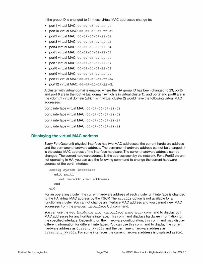
If the group ID is changed to 34 these virtual MAC addresses change to:
• port1 virtual MAC: 00-09-0f-09-22-00
• port10 virtual MAC: 00-09-0f-09-22-01
• port2 virtual MAC: 00-09-0f-09-22-02
• port3 virtual MAC: 00-09-0f-09-22-03
• port4 virtual MAC: 00-09-0f-09-22-04
• port5 virtual MAC: 00-09-0f-09-22-05
• port6 virtual MAC: 00-09-0f-09-22-06
• port7 virtual MAC: 00-09-0f-09-22-07
• port8 virtual MAC: 00-09-0f-09-22-08
• port9 virtual MAC: 00-09-0f-09-22-09
• port11 virtual MAC: 00-09-0f-09-22-0a
• port12 virtual MAC: 00-09-0f-09-22-0b
A cluster with virtual domains enabled where the HA group ID has been changed to 23, port5 and port 6 are in the root virtual domain (which is in virtual cluster1), and port7 and port8 are in the vdom_1 virtual domain (which is in virtual cluster 2) would have the following virtual MAC addresses:
port5 interface virtual MAC: 00-09-0f-09-23-05
port6 interface virtual MAC: 00-09-0f-09-23-06
port7 interface virtual MAC: 00-09-0f-09-23-27
port8 interface virtual MAC: 00-09-0f-09-23-28
Displaying the virtual MAC address
Every FortiGate unit physical interface has two MAC addresses: the current hardware address and the permanent hardware address. The permanent hardware address cannot be changed, it is the actual MAC address of the interface hardware. The current hardware address can be changed. The current hardware address is the address seen by the network. For a FortiGate unit not operating in HA, you can use the following command to change the current hardware address of the port1 interface:
config system interface
edit port1
set macaddr <mac_address>
end
end
For an operating cluster, the current hardware address of each cluster unit interface is changed to the HA virtual MAC address by the FGCP. The macaddr option is not available for a functioning cluster. You cannot change an interface MAC address and you cannot view MAC addresses from the system interface CLI command.
You can use the get hardware nic <interface_name_str> command to display both MAC addresses for any FortiGate interface. This command displays hardware information for the specified interface. Depending on their hardware configuration, this command may display different information for different interfaces. You can use this command to display the current hardware address as Current_HWaddr and the permanent hardware address as Permanent_HWaddr. For some interfaces the current hardware address is displayed as MAC.
Fortinet Technologies Inc. Page 204 FortiOS™ Handbook - High Availability for FortiOS 5.0

The command displays a great deal of information about the interface so you may have to scroll the output to find the hardware addresses.
Before HA configuration the current and permanent hardware addresses are the same. For example for one of the units in Cluster_1:
FGT60B3907503171 # get hardware nic internal
.
.
.
MAC: 02:09:0f:78:18:c9
Permanent_HWaddr: 02:09:0f:78:18:c9
.
.
.
During HA operation the current hardware address becomes the HA virtual MAC address, for example for the units in Cluster_1:
FGT60B3907503171 # get hardware nic internal
.
.
.
MAC: 00:09:0f:09:00:02
Permanent_HWaddr: 02:09:0f:78:18:c9
.
.
.
The following command output for Cluster_2 shows the same current hardware address for port1 as for the internal interface of Cluster_2, indicating a MAC address conflict.
FG300A2904500238 # get hardware nic port1
.
.
.
MAC: 00:09:0f:09:00:02
Permanent_HWaddr: 00:09:0F:85:40:FD
.
.
.
Diagnosing packet loss with two FortiGate HA clusters in the same broadcast domain
A network may experience packet loss when two FortiGate HA clusters have been deployed in the same broadcast domain. Deploying two HA clusters in the same broadcast domain can result in packet loss because of MAC address conflicts. The packet loss can be diagnosed by pinging from one cluster to the other or by pinging both of the clusters from a device within the
You can also use the diagnose hardware deviceinfo nic <interface_str> command to display both MAC addresses for any FortiGate interface.
Fortinet Technologies Inc. Page 205 FortiOS™ Handbook - High Availability for FortiOS 5.0

broadcast domain. You can resolve the MAC address conflict by changing the HA Group ID configuration of the two clusters. The HA Group ID is sometimes also called the Cluster ID.
This section describes a topology that can result in packet loss, how to determine if packets are being lost, and how to correct the problem by changing the HA Group ID.
Changing the HA group ID to avoid MAC address conflicts
Change the Group ID to change the virtual MAC address of all cluster interfaces. You can change the Group ID from the FortiGate CLI using the following command:
config system ha
set group-id <id_integer>
end
Example topology
The topology below shows two clusters. The Cluster_1 internal interfaces and the Cluster_2 port 1 interfaces are both connected to the same broadcast domain. In this topology the broadcast domain could be an internal network. Both clusters could also be connected to the Internet or to different networks.
Figure 24:Example HA topology with possible MAC address conflicts
Ping testing for packet loss
If the network is experiencing packet loss, it is possible that you will not notice a problem unless you are constantly pinging both HA clusters. During normal operation of the network you also might not notice packet loss because the loss rate may not be severe enough to timeout TCP sessions. Also many common types if TCP traffic, such as web browsing, may not be greatly affected by packet loss. However, packet loss can have a significant effect on real time protocols that deliver audio and video data.
Packet loss on a network can also be caused by IP address conflicts. Finding and fixing IP address conflicts can be difficult. However, if you are experiencing packet loss and your network contains two FortiGate HA clusters you can use the information in this article to eliminate one possible source of packet loss.
Cluster 2
Cluster 1
Port1
Port1
Port2
Port2
Internal
wan1
wan1
Internal
L2 Switch
wan2wan2
port3port3
22 SSwwiittcchh
Fortinet Technologies Inc. Page 206 FortiOS™ Handbook - High Availability for FortiOS 5.0

To test for packet loss you can set up two constant ping sessions, one to each cluster. If packet loss is occurring the two ping sessions should show alternating replies and timeouts from each cluster.
Viewing MAC address conflicts on attached switches
If two HA clusters with the same virtual MAC address are connected to the same broadcast domain (L2 switch or hub), the MAC address will conflict and bounce between the two clusters. This example Cisco switch MAC address table shows the MAC address flapping between different interfaces (1/0/1 and 1/0/4).
1 0009.0f09.0002 DYNAMIC Gi1/0/1
1 0009.0f09.0002 DYNAMIC Gi1/0/4
Synchronizing the configuration
The FGCP uses a combination of incremental and periodic synchronization to make sure that the configuration of all cluster units is synchronized to that of the primary unit.
Configuration settings that are not synchronized
The following settings are not synchronized among cluster units:
• HA override.
• HA device priority.
• The virtual cluster priority.
• The FortiGate unit host name.
• The HA priority setting for a ping server (or dead gateway detection) configuration.
• The system interface settings of the HA reserved management interface.
• The HA default route for the reserved management interface, set using the ha-mgt-interface-gateway option of the config system ha command.
Cluster_1 Cluster_2
reply timeout
reply timeout
reply timeout
timeout reply
timeout reply
reply timeout
reply timeout
timeout reply
timeout reply
timeout reply
timeout reply
Fortinet Technologies Inc. Page 207 FortiOS™ Handbook - High Availability for FortiOS 5.0

The primary unit synchronizes all other configuration settings, including the other HA configuration settings.
Disabling automatic configuration synchronization
In some cases you may want to use the following command to disable automatic synchronization of the primary unit configuration to all cluster units.
config system ha
set sync-config disable
end
When this option is disabled the cluster no longer synchronizes configuration changes. If a device failure occurs, the new primary unit may not have the same configuration as the failed primary unit. As a result, the new primary unit may process sessions differently or may not function on the network in the same way.
In most cases you should not disable automatic configuration synchronization. However, if you have disabled this feature you can use the execute ha synchronize command to manually synchronize a subordinate unit’s configuration to that of the primary unit.
You must enter execute ha synchronize commands from the subordinate unit that you want to synchronize with the primary unit. Use the execute ha manage command to access a subordinate unit CLI. See “Viewing cluster status from the CLI” on page 177.
For example, to access the first subordinate unit and force a synchronization at any time, even if automatic synchronization is disabled enter:
execute ha manage 0
execute ha synchronize start
You can use the following command to stop a synchronization that is in progress.
execute ha synchronize stop
You can use the following command to a synchronization all parts of the configuration:
execute ha synchronize all
Individual options are also available to synchronize parts of the configuration. For example, enter the following command to synchronize CA certificates:
execute ha synchronize ca
Incremental synchronization
When you log into the cluster web-based manager or CLI to make configuration changes, you are actually logging into the primary unit. All of your configuration changes are first made to the primary unit. Incremental synchronization then immediately synchronizes these changes to all of the subordinate units.
When you log into a subordinate unit CLI (for example using execute ha manage) all of the configuration changes that you make to the subordinate unit are also immediately synchronized to all cluster units, including the primary unit, using the same process.
Incremental synchronization also synchronizes other dynamic configuration information such as the DHCP server address lease database, routing table updates, IPsec SAs, MAC address tables, and so on. See “FortiGate HA compatibility with PPPoE and DHCP” on page 42 for more information about DHCP server address lease synchronization and “Synchronizing kernel routing tables” on page 215 for information about routing table updates.
Whenever a change is made to a cluster unit configuration, incremental synchronization sends the same configuration change to all other cluster units over the HA heartbeat link. An HA
Fortinet Technologies Inc. Page 208 FortiOS™ Handbook - High Availability for FortiOS 5.0

synchronization process running on the each cluster unit receives the configuration change and applies it to the cluster unit. The HA synchronization process makes the configuration change by entering a CLI command that appears to be entered by the administrator who made the configuration change in the first place.
Synchronization takes place silently, and no log messages are recorded about the synchronization activity. However, log messages can be recorded by the cluster units when the synchronization process enters CLI commands. You can see these log messages on the subordinate units if you enable event logging and set the minimum severity level to Information and then check the event log messages written by the cluster units when you make a configuration change.
You can also see these log messages on the primary unit if you make configuration changes from a subordinate unit.
Periodic synchronization
Incremental synchronization makes sure that as an administrator makes configuration changes, the configurations of all cluster units remain the same. However, a number of factors could cause one or more cluster units to go out of sync with the primary unit. For example, if you add a new unit to a functioning cluster, the configuration of this new unit will not match the configuration of the other cluster units. Its not practical to use incremental synchronization to change the configuration of the new unit.
Periodic synchronization is a mechanism that looks for synchronization problems and fixes them. Every minute the cluster compares the configuration file checksum of the primary unit with the configuration file checksums of each of the subordinate units. If all subordinate unit checksums are the same as the primary unit checksum, all cluster units are considered synchronized.
If one or more of the subordinate unit checksums is not the same as the primary unit checksum, the subordinate unit configuration is considered out of sync with the primary unit. The checksum of the out of sync subordinate unit is checked again every 15 seconds. This re-checking occurs in case the configurations are out of sync because an incremental configuration sequence has not completed. If the checksums do not match after 5 checks the subordinate unit that is out of sync retrieves the configuration from the primary unit. The subordinate unit then reloads its configuration and resumes operating as a subordinate unit with the same configuration as the primary unit.
The configuration of the subordinate unit is reset in this way because when a subordinate unit configuration gets out of sync with the primary unit configuration there is no efficient way to determine what the configuration differences are and to correct them. Resetting the subordinate unit configuration becomes the most efficient way to resynchronize the subordinate unit.
Synchronization requires that all cluster units run the same FortiOS firmware build. If some cluster units are running different firmware builds, then unstable cluster operation may occur and the cluster units may not be able to synchronize correctly.
Re-installing the firmware build running on the primary unit forces the primary unit to upgrade all cluster units to the same firmware build.
Fortinet Technologies Inc. Page 209 FortiOS™ Handbook - High Availability for FortiOS 5.0

Console messages when configuration synchronization succeeds
When a cluster first forms, or when a new unit is added to a cluster as a subordinate unit, the following messages appear on the CLI console to indicate that the unit joined the cluster and had its configuring synchronized with the primary unit.
slave's configuration is not in sync with master's, sequence:0
slave's configuration is not in sync with master's, sequence:1
slave's configuration is not in sync with master's, sequence:2
slave's configuration is not in sync with master's, sequence:3
slave's configuration is not in sync with master's, sequence:4
slave starts to sync with master
logout all admin users
slave succeeded to sync with master
Console messages when configuration synchronization fails
If you connect to the console of a subordinate unit that is out of synchronization with the primary unit, messages similar to the following are displayed.
slave is not in sync with master, sequence:0. (type 0x3)
slave is not in sync with master, sequence:1. (type 0x3)
slave is not in sync with master, sequence:2. (type 0x3)
slave is not in sync with master, sequence:3. (type 0x3)
slave is not in sync with master, sequence:4. (type 0x3)
global compared not matched
If synchronization problems occur the console message sequence may be repeated over and over again. The messages all include a type value (in the example type 0x3). The type value can help Fortinet Support diagnose the synchronization problem.
Table 5: HA out of sync object messages and the configuration objects that they reference
Out of Sync Message Configuration Object
HA_SYNC_SETTING_CONFIGURATION = 0x03
/data/config
HA_SYNC_SETTING_AV = 0x10
HA_SYNC_SETTING_VIR_DB = 0x11 /etc/vir
HA_SYNC_SETTING_SHARED_LIB = 0x12
/data/lib/libav.so
HA_SYNC_SETTING_SCAN_UNIT = 0x13 /bin/scanunitd
HA_SYNC_SETTING_IMAP_PRXY = 0x14 /bin/imapd
HA_SYNC_SETTING_SMTP_PRXY = 0x15 /bin/smtp
HA_SYNC_SETTING_POP3_PRXY = 0x16 /bin/pop3
HA_SYNC_SETTING_HTTP_PRXY = 0x17 /bin/thttp
HA_SYNC_SETTING_FTP_PRXY = 0x18 /bin/ftpd
HA_SYNC_SETTING_FCNI = 0x19 /etc/fcni.dat
Fortinet Technologies Inc. Page 210 FortiOS™ Handbook - High Availability for FortiOS 5.0
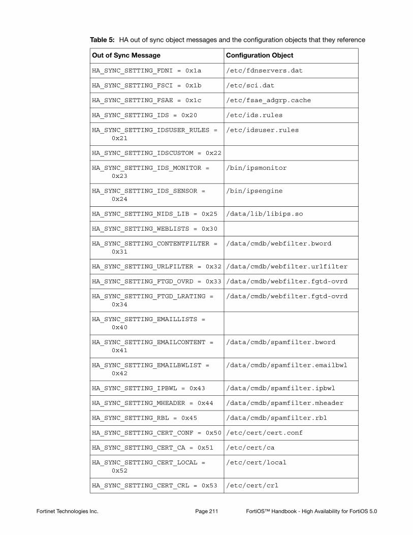
HA_SYNC_SETTING_FDNI = 0x1a /etc/fdnservers.dat
HA_SYNC_SETTING_FSCI = 0x1b /etc/sci.dat
HA_SYNC_SETTING_FSAE = 0x1c /etc/fsae_adgrp.cache
HA_SYNC_SETTING_IDS = 0x20 /etc/ids.rules
HA_SYNC_SETTING_IDSUSER_RULES = 0x21
/etc/idsuser.rules
HA_SYNC_SETTING_IDSCUSTOM = 0x22
HA_SYNC_SETTING_IDS_MONITOR = 0x23
/bin/ipsmonitor
HA_SYNC_SETTING_IDS_SENSOR = 0x24
/bin/ipsengine
HA_SYNC_SETTING_NIDS_LIB = 0x25 /data/lib/libips.so
HA_SYNC_SETTING_WEBLISTS = 0x30
HA_SYNC_SETTING_CONTENTFILTER = 0x31
/data/cmdb/webfilter.bword
HA_SYNC_SETTING_URLFILTER = 0x32 /data/cmdb/webfilter.urlfilter
HA_SYNC_SETTING_FTGD_OVRD = 0x33 /data/cmdb/webfilter.fgtd-ovrd
HA_SYNC_SETTING_FTGD_LRATING = 0x34
/data/cmdb/webfilter.fgtd-ovrd
HA_SYNC_SETTING_EMAILLISTS = 0x40
HA_SYNC_SETTING_EMAILCONTENT = 0x41
/data/cmdb/spamfilter.bword
HA_SYNC_SETTING_EMAILBWLIST = 0x42
/data/cmdb/spamfilter.emailbwl
HA_SYNC_SETTING_IPBWL = 0x43 /data/cmdb/spamfilter.ipbwl
HA_SYNC_SETTING_MHEADER = 0x44 /data/cmdb/spamfilter.mheader
HA_SYNC_SETTING_RBL = 0x45 /data/cmdb/spamfilter.rbl
HA_SYNC_SETTING_CERT_CONF = 0x50 /etc/cert/cert.conf
HA_SYNC_SETTING_CERT_CA = 0x51 /etc/cert/ca
HA_SYNC_SETTING_CERT_LOCAL = 0x52
/etc/cert/local
HA_SYNC_SETTING_CERT_CRL = 0x53 /etc/cert/crl
Table 5: HA out of sync object messages and the configuration objects that they reference
Out of Sync Message Configuration Object
Fortinet Technologies Inc. Page 211 FortiOS™ Handbook - High Availability for FortiOS 5.0

Comparing checksums of cluster units
You can use the diagnose sys ha showcsum command to compare the configuration checksums of all cluster units. The output of this command shows checksums labelled global and all as well as checksums for each of the VDOMs including the root VDOM. The get system ha-nonsync-csum command can be used to display similar information; however, this command is intended to be used by FortiManager.
The primary unit and subordinate unit checksums should be the same. If they are not you can use the execute ha synchronize command to force a synchronization.
The following command output is for the primary unit of a cluster that does not have multiple VDOMs enabled:
diagnose sys ha showcsum
is_manage_master()=1, is_root_master()=1
debugzone
global: a0 7f a7 ff ac 00 d5 b6 82 37 cc 13 3e 0b 9b 77
root: 43 72 47 68 7b da 81 17 c8 f5 10 dd fd 6b e9 57
all: c5 90 ed 22 24 3e 96 06 44 35 b6 63 7c 84 88 d5
checksum
global: a0 7f a7 ff ac 00 d5 b6 82 37 cc 13 3e 0b 9b 77
root: 43 72 47 68 7b da 81 17 c8 f5 10 dd fd 6b e9 57
all: c5 90 ed 22 24 3e 96 06 44 35 b6 63 7c 84 88 d5
The following command output is for a subordinate unit of the same cluster:
diagnose sys ha showcsum
is_manage_master()=0, is_root_master()=0
debugzone
global: a0 7f a7 ff ac 00 d5 b6 82 37 cc 13 3e 0b 9b 77
root: 43 72 47 68 7b da 81 17 c8 f5 10 dd fd 6b e9 57
all: c5 90 ed 22 24 3e 96 06 44 35 b6 63 7c 84 88 d5
checksum
global: a0 7f a7 ff ac 00 d5 b6 82 37 cc 13 3e 0b 9b 77
root: 43 72 47 68 7b da 81 17 c8 f5 10 dd fd 6b e9 57
all: c5 90 ed 22 24 3e 96 06 44 35 b6 63 7c 84 88 d5
HA_SYNC_SETTING_DB_VER = 0x55
HA_GET_DETAIL_CSUM = 0x71
HA_SYNC_CC_SIG = 0x75 /etc/cc_sig.dat
HA_SYNC_CC_OP = 0x76 /etc/cc_op
HA_SYNC_CC_MAIN = 0x77 /etc/cc_main
HA_SYNC_FTGD_CAT_LIST = 0x7a /migadmin/webfilter/ublock/ftgd/ data/
Table 5: HA out of sync object messages and the configuration objects that they reference
Out of Sync Message Configuration Object
Fortinet Technologies Inc. Page 212 FortiOS™ Handbook - High Availability for FortiOS 5.0

The following example shows using this command for the primary unit of a cluster with multiple VDOMs. Two VDOMs have been added named test and Eng_vdm.
From the primary unit:
config global
sys ha showcsum
is_manage_master()=1, is_root_master()=1
debugzone
global: 65 75 88 97 2d 58 1b bf 38 d3 3d 52 5b 0e 30 a9
test: a5 16 34 8c 7a 46 d6 a4 1e 1f c8 64 ec 1b 53 fe
root: 3c 12 45 98 69 f2 d8 08 24 cf 02 ea 71 57 a7 01
Eng_vdm: 64 51 7c 58 97 79 b1 b3 b3 ed 5c ec cd 07 74 09
all: 30 68 77 82 a1 5d 13 99 d1 42 a3 2f 9f b9 15 53
checksum
global: 65 75 88 97 2d 58 1b bf 38 d3 3d 52 5b 0e 30 a9
test: a5 16 34 8c 7a 46 d6 a4 1e 1f c8 64 ec 1b 53 fe
root: 3c 12 45 98 69 f2 d8 08 24 cf 02 ea 71 57 a7 01
Eng_vdm: 64 51 7c 58 97 79 b1 b3 b3 ed 5c ec cd 07 74 09
all: 30 68 77 82 a1 5d 13 99 d1 42 a3 2f 9f b9 15 53
From the subordinate unit:
config global
diagnose sys ha showcsum
is_manage_master()=0, is_root_master()=0
debugzone
global: 65 75 88 97 2d 58 1b bf 38 d3 3d 52 5b 0e 30 a9
test: a5 16 34 8c 7a 46 d6 a4 1e 1f c8 64 ec 1b 53 fe
root: 3c 12 45 98 69 f2 d8 08 24 cf 02 ea 71 57 a7 01
Eng_vdm: 64 51 7c 58 97 79 b1 b3 b3 ed 5c ec cd 07 74 09
all: 30 68 77 82 a1 5d 13 99 d1 42 a3 2f 9f b9 15 53
checksum
global: 65 75 88 97 2d 58 1b bf 38 d3 3d 52 5b 0e 30 a9
test: a5 16 34 8c 7a 46 d6 a4 1e 1f c8 64 ec 1b 53 fe
root: 3c 12 45 98 69 f2 d8 08 24 cf 02 ea 71 57 a7 01
Eng_vdm: 64 51 7c 58 97 79 b1 b3 b3 ed 5c ec cd 07 74 09
all: 30 68 77 82 a1 5d 13 99 d1 42 a3 2f 9f b9 15 53
How to diagnose HA out of sync messages
This section describes how to use the commands diagnose sys ha showcsum and diagnose debug to diagnose the cause of HA out of sync messages.
If HA synchronization is not successful, use the following procedures on each cluster unit to find the cause.
To determine why HA synchronization does not occur
1. Connect to each cluster unit CLI by connected to the console port.
Fortinet Technologies Inc. Page 213 FortiOS™ Handbook - High Availability for FortiOS 5.0

2. Enter the following commands to enable debugging and display HA out of sync messages. diagnose debug enable
diagnose debug console timestamp enable
diagnose debug application hatalk -1
diagnose debug application hasync -1
Collect the console output and compare the out of sync messages with the information in Table 5 on page 210.
3. Enter the following commands to turn off debugging.diagnose debug disable
diagnose debug reset
To determine what part of the configuration is causing the problem
If the previous procedure displays messages that include sync object 0x30 (for example, HA_SYNC_SETTING_CONFIGURATION = 0x03) there is a synchronization problem with the configuration. Use the following steps to determine the part of the configuration that is causing the problem.
If your cluster consists of two cluster units, use this procedure to capture the configuration checksums for each unit. If your cluster consists of more that two cluster units, repeat this procedure for all cluster units that returned messages that include 0x30 sync object messages.
1. Connect to each cluster unit CLI by connected to the console port.
2. Enter the following command to turn on terminal capturediagnose debug enable
3. Enter the following command to stop HA synchronization.execute ha sync stop
4. Enter the following command to display configuration checksums.diagnose sys ha showcsum 1
5. Copy the output to a text file.
6. Repeat for all affected units.
7. Compare the text file from the primary unit with the text file from each cluster unit to find the checksums that do not match.
You can use a diff function to compare text files.
8. Repeat steps 4 to 7 for each checksum level:diagnose sys ha showcsum 2
diagnose sys ha showcsum 3
diagnose sys ha showcsum 4
diagnose sys ha showcsum 5
diagnose sys ha showcsum 6
diagnose sys ha showcsum 7
diagnose sys ha showcsum 8
9. When the non-matching checksum is found, attempt to drill down further. This is possible for objects that have sub-components.
For example you can enter the following commands:diagnose sys ha showcsum system.global
diagnose sys ha showcsum system.interface
Generally it is the first non-matching checksum in one of the levels that is the cause of the synchronization problem.
10.Attempt to can remove/change the part of the configuration that is causing the problem. You can do this by making configuration changes from the primary unit or subordinate unit CLI.
Fortinet Technologies Inc. Page 214 FortiOS™ Handbook - High Availability for FortiOS 5.0

11.Enter the following commands to start HA configuration and stop debugging:execute ha sync start
diagnose debug disable
diagnose debug reset
Recalculating the checksums to resolve out of sync messages
Sometimes an error can occur when checksums are being calculated by the cluster. As a result of this calculation error the CLI console could display out of sync error messages even though the cluster is otherwise operating normally. You can also sometimes see checksum calculation errors in diagnose sys ha showcsum command output when the checksums listed in the debugzone output don’t match the checksums in the checksum part of the output.
One solution to this problem could be to re-calculate the checksums. The re-calculated checksums should match and the out of sync error messages should stop appearing.
You can use the following command to re-calculate HA checksums:
diagnose sys ha csum-recalculate [<vdom-name> | global]
Just entering the command without options recalculates all checksums. You can specify a VDOM name to just recalculate the checksums for that VDOM. You can also enter global to recalculate the global checksum.
Synchronizing kernel routing tables
In a functioning cluster, the primary unit keeps all subordinate unit kernel routing tables (also called the forwarding information base FIB) up to date and synchronized with the primary unit. After a failover, because of these routing table updates the new primary unit does not have to populate its kernel routing table before being able to route traffic. This gives the new primary unit time to rebuild its regular routing table after a failover.
Use the following command to view the regular routing table. This table contains all of the configured routes and routes acquired from dynamic routing protocols and so on. This routing table is not synchronized. On subordinate units this command will not produce the same output as on the primary unit.
get router info routing-table
Use the following command to view the kernel routing table (FIB). This is the list of resolved routes actually being used by the FortiOS kernel. The output of this command should be the same on the primary unit and the subordinate units.
get router info kernel
This section describes how clusters handle dynamic routing failover and also describes how to use CLI commands to control the timing of routing table updates of the subordinate unit routing tables from the primary unit.
Configuring graceful restart for dynamic routing failover
When an HA failover occurs, neighbor routers will detect that the cluster has failed and remove it from the network until the routing topology stabilizes. During the time the routers may stop sending IP packets to the cluster and communications sessions that would normally be processed by the cluster may time out or be dropped. Also the new primary unit will not receive routing updates and so will not be able to build and maintain its routing database.
You can configure graceful restart (also called nonstop forwarding (NSF)) as described in RFC3623 (Graceful OSPF Restart) to solve the problem of dynamic routing failover. If graceful
Fortinet Technologies Inc. Page 215 FortiOS™ Handbook - High Availability for FortiOS 5.0

restart is enabled on neighbor routers, they will keep sending packets to the cluster following the HA failover instead of removing it from the network. The neighboring routers assume that the cluster is experiencing a graceful restart.
After the failover, the new primary unit can continue to process communication sessions using the synchronized routing data received from the failed primary unit before the failover. This gives the new primary unit time to update its routing table after the failover.
You can use the following commands to enable graceful restart or NSF on Cisco routers:
router ospf 1
log-adjacency-changes
nsf ietf helper strict-lsa-checking
If the cluster is running BGP, use the following command to enable graceful restart for BGP:
config router bgp
set graceful-restart enable
end
You can also add BGP neighbors and configure the cluster unit to notify these neighbors that it supports graceful restart.
config router bgp
config neighbor
edit <neighbor_address_Ipv4>
set capability-graceful-restart enable
end
end
If the cluster is running OSPF, use the following command to enable graceful restart for OSFP:
config router ospf
set restart-mode graceful-restart
end
To make sure the new primary unit keeps its synchronized routing data long enough to acquire new routing data, you should also increase the HA route time to live, route wait, and route hold values to 60 using the following CLI command:
config system ha
set route-ttl 60
set route-wait 60
set route-hold 60
end
Enabling BGP graceful restart causes the FortiGate's BGP process to restart which can temporarily disrupt traffic through the cluster. So normally you should wait for a quiet time or a maintenance period to enable BGP graceful restart
Fortinet Technologies Inc. Page 216 FortiOS™ Handbook - High Availability for FortiOS 5.0
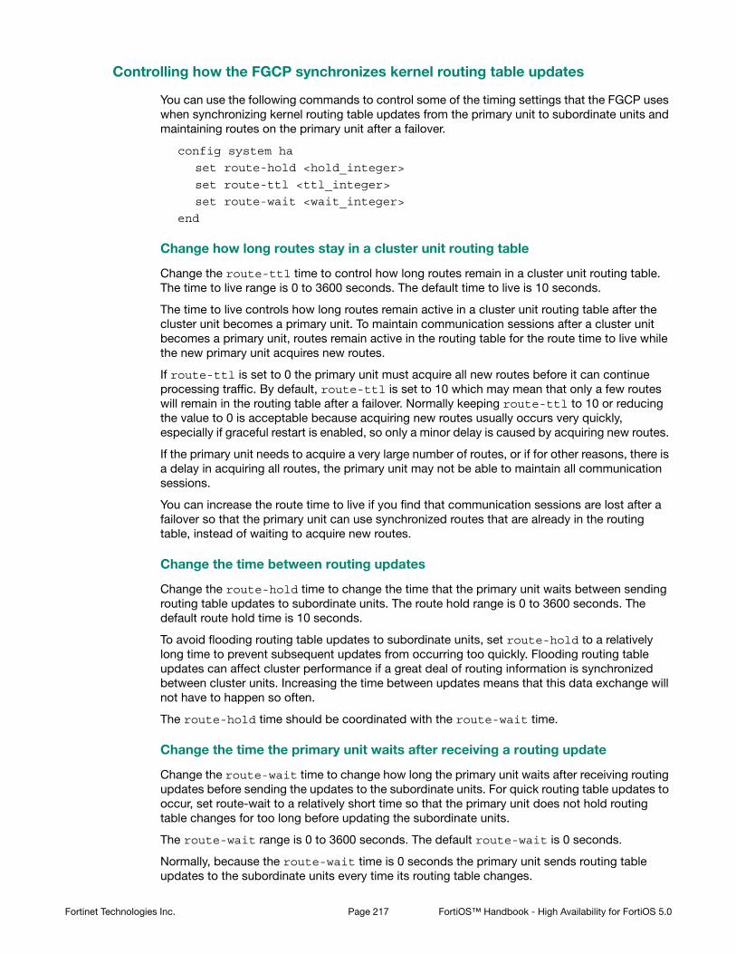
Controlling how the FGCP synchronizes kernel routing table updates
You can use the following commands to control some of the timing settings that the FGCP uses when synchronizing kernel routing table updates from the primary unit to subordinate units and maintaining routes on the primary unit after a failover.
config system ha
set route-hold <hold_integer>
set route-ttl <ttl_integer>
set route-wait <wait_integer>
end
Change how long routes stay in a cluster unit routing table
Change the route-ttl time to control how long routes remain in a cluster unit routing table. The time to live range is 0 to 3600 seconds. The default time to live is 10 seconds.
The time to live controls how long routes remain active in a cluster unit routing table after the cluster unit becomes a primary unit. To maintain communication sessions after a cluster unit becomes a primary unit, routes remain active in the routing table for the route time to live while the new primary unit acquires new routes.
If route-ttl is set to 0 the primary unit must acquire all new routes before it can continue processing traffic. By default, route-ttl is set to 10 which may mean that only a few routes will remain in the routing table after a failover. Normally keeping route-ttl to 10 or reducing the value to 0 is acceptable because acquiring new routes usually occurs very quickly, especially if graceful restart is enabled, so only a minor delay is caused by acquiring new routes.
If the primary unit needs to acquire a very large number of routes, or if for other reasons, there is a delay in acquiring all routes, the primary unit may not be able to maintain all communication sessions.
You can increase the route time to live if you find that communication sessions are lost after a failover so that the primary unit can use synchronized routes that are already in the routing table, instead of waiting to acquire new routes.
Change the time between routing updates
Change the route-hold time to change the time that the primary unit waits between sending routing table updates to subordinate units. The route hold range is 0 to 3600 seconds. The default route hold time is 10 seconds.
To avoid flooding routing table updates to subordinate units, set route-hold to a relatively long time to prevent subsequent updates from occurring too quickly. Flooding routing table updates can affect cluster performance if a great deal of routing information is synchronized between cluster units. Increasing the time between updates means that this data exchange will not have to happen so often.
The route-hold time should be coordinated with the route-wait time.
Change the time the primary unit waits after receiving a routing update
Change the route-wait time to change how long the primary unit waits after receiving routing updates before sending the updates to the subordinate units. For quick routing table updates to occur, set route-wait to a relatively short time so that the primary unit does not hold routing table changes for too long before updating the subordinate units.
The route-wait range is 0 to 3600 seconds. The default route-wait is 0 seconds.
Normally, because the route-wait time is 0 seconds the primary unit sends routing table updates to the subordinate units every time its routing table changes.
Fortinet Technologies Inc. Page 217 FortiOS™ Handbook - High Availability for FortiOS 5.0

Once a routing table update is sent, the primary unit waits the route-hold time before sending the next update.
Usually routing table updates are periodic and sporadic. Subordinate units should receive these changes as soon as possible so route-wait is set to 0 seconds. route-hold can be set to a relatively long time because normally the next route update would not occur for a while.
In some cases, routing table updates can occur in bursts. A large burst of routing table updates can occur if a router or a link on a network fails or changes. When a burst of routing table updates occurs, there is a potential that the primary unit could flood the subordinate units with routing table updates. Flooding routing table updates can affect cluster performance if a great deal of routing information is synchronized between cluster units. Setting route-wait to a longer time reduces the frequency of additional updates are and prevents flooding of routing table updates from occurring.
Synchronizing IPsec VPN SAs
The FGCP synchronizes IPsec security associations (SAs) between cluster members so that if a failover occurs, the cluster can resume IPsec sessions without having to establish new SAs. The result is improved failover performance because IPsec sessions are not interrupted to establish new SAs. Also, establishing a large number of SAs can reduce cluster performance.
The FGCP implements slightly different synchronization mechanisms for IKEv1 and IKEv2.
Synchronizing SAs for IKEv1
When an SA is synchronized to the subordinate units. the sequence number is set to the maximum sequence number. After a failover, all inbound traffic that connects with the new primary unit and uses the SA will be accepted without needing to re-key. However, first outbound packet to use the SA causes the sequence number to overflow and so causes the new primary unit to re-key the SA.
Please note the following:
• The cluster synchronizes all IPsec SAs.
• IPsec SAs are not synchronized until the IKE process has finished synchronizing the ISAKMP SAs. This is required in for dialup tunnels since it is the synchronizing of the ISAKMP SA that creates the dialup tunnel.
• A dialup interface is created as soon as the phase1 is complete. This ensures that the when HA synchronizes phase1 information the dialup name is included.
• If the IKE process re-starts for any reason it deletes any dialup tunnels that exist. This forces the peer to re-key them.
• IPsec SA deletion happens immediately. Routes associated with a dialup tunnel that is being deleted are cleaned up synchronously as part of the delete, rather than waiting for the SA hard-expiry.
• The FGCP does not sync the IPsec tunnel MTU from the primary unit to the subordinate units. This means that after HA failover if the first packet received by the FortiGate unit arrives after the HA route has been deleted and before the new route is added and the packet is larger than the default MTU of 1024 then the FortiGate unit sends back an ICMP fragmentation required. However, as soon as routing is re-established then the MTU will be corrected and traffic will flow.
Synchronizing SAs for IKEv2
Due to the way the IKEv2 protocol is designed the FGCP cannot use exactly the same solution that is used for synchronizing IKEv1 SAs, though it is similar.
Fortinet Technologies Inc. Page 218 FortiOS™ Handbook - High Availability for FortiOS 5.0

For IKEv2, like IKEv1, the FGCP synchronizes IKE and ISAKMP SAs from the primary unit to the subordinate units. However, for IKEv2 the FGCP cannot actually use this IKE SA to send/receive IKE traffic because IKEv2 includes a sequence number in every IKE message and thus it would require synchronizing every message to the subordinate units to keep the sequence numbers on the subordinate units up to date.
After a failover when the new primary unit accepts incoming IKEv2 sessions, as in IKEv1, the primary unit uses the synchronized SA to decrypt the traffic before passing it through to its destination. For outgoing sessions, because the synchronized SA has an old sequence number, the primary unit negotiates a new SA. This is different from IKEv1 where the existing SA is re-keyed.
Normally for IKEv2 the new primary unit could just negotiate a CHILD_SA using the synchronized SA. However, because the sequence numbers are not up-to-date, as noted above, the synchronized SA cannot be used and the primary unit must instead negotiate a whole new SA.
Link failover (port monitoring or interface monitoring)
Link failover means that if a monitored interface fails, the cluster reorganizes to reestablish a link to the network that the monitored interface was connected to and to continue operating with minimal or no disruption of network traffic.
You configure monitored interfaces (also called interface monitoring or port monitoring) by selecting the interfaces to monitor as part of the cluster HA configuration.
You can monitor up to 64 interfaces.
The interfaces that you can monitor appear on the port monitor list. You can monitor all FortiGate interfaces including redundant interfaces and 802.3ad aggregate interfaces.
You cannot monitor the following types of interfaces (you cannot select the interfaces on the port monitor list):
• FortiGate interfaces that contain an internal switch.
• VLAN subinterfaces.
• IPsec VPN interfaces.
• Individual physical interfaces that have been added to a redundant or 802.3ad aggregate interface.
• FortiGate-5000 series backplane interfaces that have not been configured as network interfaces.
If you are configuring a virtual cluster you can create a different port monitor configuration for each virtual cluster. Usually for each virtual cluster you would monitor the interfaces that have been added to the virtual domains in each virtual cluster.
Wait until after the cluster is up and running to enable interface monitoring. You do not need to configure interface monitoring to get a cluster up and running and interface monitoring will cause failovers if for some reason during initial setup a monitored interface has become disconnected. You can always enable interface monitoring once you have verified that the cluster is connected and operating properly.
You should only monitor interfaces that are connected to networks, because a failover may occur if you monitor an unconnected interface.
Fortinet Technologies Inc. Page 219 FortiOS™ Handbook - High Availability for FortiOS 5.0

To enable interface monitoring - web-based manager
Use the following steps to monitor the port1 and port2 interfaces of a cluster.
1. Connect to the cluster web-based manager.
2. Go to System > Config > HA and edit the primary unit (Role is MASTER).
3. Select the Port Monitor check boxes for the port1 and port2 interfaces and select OK.
The configuration change is synchronized to all cluster units.
To enable interface monitoring - CLI
Use the following steps to monitor the port1 and port2 interfaces of a cluster.
1. Connect to the cluster CLI.
2. Enter the following command to enable interface monitoring for port1 and port2.configure system ha
set monitor port1 port2
end
The following example shows how to enable monitoring for the external, internal, and DMZ interfaces.
config system ha
set monitor external internal dmz
end
With interface monitoring enabled, during cluster operation, the cluster monitors each cluster unit to determine if the monitored interfaces are operating and connected. Each cluster unit can detect a failure of its network interface hardware. Cluster units can also detect if its network interfaces are disconnected from the switch they should be connected to.
Because the primary unit receives all traffic processed by the cluster, a cluster can only process traffic from a network if the primary unit can connect to it. So, if the link between a network and the primary unit fails, to maintain communication with this network, the cluster must select a different primary unit; one that is still connected to the network. Unless another link failure has occurred, the new primary unit will have an active link to the network and will be able to maintain communication with it.
To support link failover, each cluster unit stores link state information for all monitored cluster units in a link state database. All cluster units keep this link state database up to date by sharing link state information with the other cluster units. If one of the monitored interfaces on one of the cluster units becomes disconnected or fails, this information is immediately shared with all cluster units.
If a monitored interface on the primary unit fails
If a monitored interface on the primary unit fails, the cluster renegotiates to select a new primary unit using the process described in “Primary unit selection” on page 31. Because the cluster unit with the failed monitored interface has the lowest monitor priority, a different cluster unit becomes the primary unit. The new primary unit should have fewer link failures.
After the failover, the cluster resumes and maintains communication sessions in the same way as for a device failure. See “Device failover” on page 192.
Cluster units cannot determine if the switch that its interfaces are connected to is still connected to the network. However, you can use remote IP monitoring to make sure that the cluster unit can connect to downstream network devices. See “Remote link failover” on page 226.
Fortinet Technologies Inc. Page 220 FortiOS™ Handbook - High Availability for FortiOS 5.0
If a monitored interface on a subordinate unit fails
If a monitored interface on a subordinate unit fails, this information is shared with all cluster units. The cluster does not renegotiate. The subordinate unit with the failed monitored interface continues to function in the cluster.
In an active-passive cluster after a subordinate unit link failover, the subordinate unit continues to function normally as a subordinate unit in the cluster.
In an active-active cluster after a subordinate unit link failure:
• The subordinate unit with the failed monitored interface can continue processing connections between functioning interfaces. However, the primary unit stops sending sessions to a subordinate unit that use any failed monitored interfaces on the subordinate unit.
• If session pickup is enabled, all sessions being processed by the subordinate unit failed interface that can be are failed over to other cluster units. Sessions that cannot be failed over are lost and have to be restarted.
• If session pickup is not enabled all sessions being processed by the subordinate unit failed interface are lost.
How link failover maintains traffic flow
Monitoring an interface means that the interface is connected to a high priority network. As a high priority network, the cluster should maintain traffic flow to and from the network, even if a link failure occurs. Because the primary unit receives all traffic processed by the cluster, a cluster can only process traffic from a network if the primary unit can connect to it. So, if the link that the primary unit has to a high priority network fails, to maintain traffic flow to and from this network, the cluster must select a different primary unit. This new primary unit should have an active link to the high priority network.
Fortinet Technologies Inc. Page 221 FortiOS™ Handbook - High Availability for FortiOS 5.0

Figure 25:A link failure causes a cluster to select a new primary unit
If a monitored interface on the primary unit fails, the cluster renegotiates and selects the cluster unit with the highest monitor priority to become the new primary unit. The cluster unit with the highest monitor priority is the cluster unit with the most monitored interfaces connected to networks.
After a link failover, the primary unit processes all traffic and all subordinate units, even the cluster unit with the link failure, share session and link status. In addition all configuration changes, routes, and IPsec SAs are synchronized to the cluster unit with the link failure.
In an active-active cluster, the primary unit load balances traffic to all the units in the cluster. The cluster unit with the link failure can process connections between its functioning interfaces (for, example if the cluster has connections to an internal, external, and DMZ network, the cluster unit with the link failure can still process connections between the external and DMZ networks).
If a monitored interface on a subordinate unit fails, the subordinate unit shares this information with all cluster units. The cluster does not renegotiate. The subordinate unit with the failed monitored interface continues to function in the cluster. In an active-active cluster, the subordinate unit can continue processing connections between functioning interfaces. The primary unit re-distributes traffic that was being processed by the failed interface of the subordinate unit to other cluster units. If session pickup is enabled, similar to a failover, some of these sessions continue while others must restart. See “Session failover (session pick-up)” on page 231.
Recovery after a link failover and controlling primary unit selection (controlling falling back to the prior primary unit)
If you find and correct the problem that caused a link failure (for example, re-connect a disconnected network cable) the cluster updates its link state database and re-negotiates to select a primary unit.
Packets from Internal network
Primary Unit
Primary Unit
Primary Unit
Packets from Internal network
Cluster SelectsNew Primary Unit
Link FailureOccurs
LinkFailure
P i U it
Packets from Internal network
LinkFailure
Fortinet Technologies Inc. Page 222 FortiOS™ Handbook - High Availability for FortiOS 5.0

What happens next depends on how the cluster configuration affects primary unit selection:
• The former primary unit will once again become the primary unit (falling back to becoming the primary unit)
• The primary unit will not change.
As described in “Displaying cluster unit age differences” on page 34, when the link is restored, if no options are configured to control primary unit selection and the cluster age difference is less than 300 seconds the former primary unit will once again become the primary unit. If the age differences are greater than 300 seconds then a new primary unit is not selected. Since you have no control on the age difference the outcome can be unpredictable. This is not a problem in cases where its not important which unit becomes the primary unit.
Preventing a primary unit change after a failed link is restored
Some organizations will not want the cluster to change primary units when the link is restored. Instead they would rather wait to restore the primary unit during a maintenance window. This functionality is not directly supported, but you can experiment with changing some primary unit selection settings. For example, in most cases it should work to enable override on all cluster units and make sure their priorities are the same. This should mean that the primary unit should not change after a failed link is restored.
Then, when you want to restore the original primary unit during a maintenance window you can just set its Device Priority higher. After it becomes the primary unit you can reset all device priorities to the same value. Alternatively during a maintenance window you could reboot the current primary unit and any subordinate units except the one that you want to become the primary unit.
If the override CLI keyword is enabled on one or more cluster units and the device priority of a cluster unit is set higher than the others, when the link failure is repaired and the cluster unit with the highest device priority will always become the primary unit.
Testing link failover
You can test link failure by disconnecting the network cable from a monitored interface of a cluster unit. If you disconnect a cable from a primary unit monitored interface the cluster should renegotiate and select one of the other cluster units as the primary unit. You can also verify that traffic received by the disconnected interface continues to be processed by the cluster after the failover.
If you disconnect a cable from a subordinate unit interface the cluster will not renegotiate.
Updating MAC forwarding tables when a link failover occurs
When a FortiGate HA cluster is operating and a monitored interface fails on the primary unit, the primary unit usually becomes a subordinate unit and another cluster unit becomes the primary unit. After a link failover, the new primary unit sends gratuitous ARP packets to refresh the MAC forwarding tables (also called arp tables) of the switches connected to the cluster. This is normal link failover operation (for more information, see “Link failover (port monitoring or interface monitoring)” on page 219).
Even when gratuitous ARP packets are sent, some switches may not be able to detect that the primary unit has become a subordinate unit and will keep sending packets to the former primary unit. This can occur if the switch does not detect the failure and does not clear its MAC forwarding table.
You have another option available to make sure the switch detects the failover and clears its MAC forwarding tables. You can use the following command to cause a cluster unit with a
Fortinet Technologies Inc. Page 223 FortiOS™ Handbook - High Availability for FortiOS 5.0

monitored interface link failure to briefly shut down all of its interfaces (except the heartbeat interfaces) after the failover occurs:
config system ha
set link-failed-signal enable
end
Usually this means each interface of the former primary unit is shut down for about a second. When this happens the switch should be able to detect this failure and clear its MAC forwarding tables of the MAC addresses of the former primary unit and pickup the MAC addresses of the new primary unit. Each interface will shut down for a second but the entire process usually takes a few seconds. The more interfaces the FortiGate unit has, the longer it will take.
Normally, the new primary unit also sends gratuitous ARP packets that also help the switch update its MAC forwarding tables to connect to the new primary unit. If link-failed-signal is enabled, sending gratuitous ARP packets is optional and can be disabled if you don‘t need it or if its causing problems. See “Disabling gratuitous ARP packets after a failover” on page 202.
Multiple link failures
Every time a monitored interface fails, the cluster repeats the processes described above. If multiple monitored interfaces fail on more than one cluster unit, the cluster continues to negotiate to select a primary unit that can provide the most network connections.
Example link failover scenarios
For the following examples, assume a cluster configuration consisting of two FortiGate units (FGT_1 and FGT_2) connected to three networks: internal using port2, external using port1, and DMZ using port3. In the HA configuration, the device priority of FGT_1 is set higher than the unit priority of FGT_2.
The cluster processes traffic flowing between the internal and external networks, between the internal and DMZ networks, and between the external and DMZ networks. If there are no link failures, FGT1 becomes the primary unit because it has the highest device priority.
Fortinet Technologies Inc. Page 224 FortiOS™ Handbook - High Availability for FortiOS 5.0

Figure 26:Sample link failover scenario topology
Example: the port1 link on FGT_1 fails
If the port1 link on FGT_1 fails, FGT_2 becomes primary unit because it has fewer interfaces with a link failure. If the cluster is operating in active-active mode, the cluster load balances traffic between the internal network (port2) and the DMZ network (port3). Traffic between the Internet (port1) and the internal network (port2) and between the Internet (port1) and the DMZ network (port3) is processed by the primary unit only.
Example: port2 on FGT_1 and port1 on FGT_2 fail
If port2 on FGT_1 and port1 on FGT_2 fail, then FGT_1 becomes the primary unit. After both of these link failures, both cluster units have the same monitor priority. So the cluster unit with the highest device priority (FGT_1) becomes the primary unit.
Only traffic between the Internet (port1) and DMZ (port3) networks can pass through the cluster and the traffic is handled by the primary unit only. No load balancing will occur if the cluster is operating in active-active mode.
Subsecond failover
HA link failover supports subsecond failover (that is a failover time of less than one second). Subsecond failover is available for interfaces that can issue a link failure system call when the interface goes down. When an interface experiences a link failure and sends the link failure system call, the FGCP receives the system call and initiates a link failover.
For interfaces that do not support subsecond failover, port monitoring regularly polls the connection status of monitored interfaces. When a check finds that an interface has gone down, port monitoring causes a link failover. Subsecond failover results in a link failure being detected sooner because the system doesn’t have to wait for the next poll to find out about the failure.
DMZNetwork
InternalNetwork
Router
Port1
Interface Monitoring
Enabled
Port2
Interface Monitoring
Enabled
Port2
Interface Monitoring
Enabled
Port3
Interface Monitoring
Disabled
Port1
Interface Monitoring
Enabled
Switch
Switch
Switch
S2
oni
Fortinet Technologies Inc. Page 225 FortiOS™ Handbook - High Availability for FortiOS 5.0

Subsecond failover requires interfaces that support sending the link failure system call. This functionality is available for:
• Interfaces with network processors (NPx)
• Interfaces with content processors (CP4, CP5, CP6, etc.)
• Interfaces in Fortinet Mezzanine Cards that include network and content processors (FMC-XD2, FMC-XG2, etc.)
• Accelerated interface modules (FortiGate-ASM-FB4, ADM-FB8, ADM-XB2, ADM-XD4, RTM-XD2 etc).
• Interfaces in security processor modules (FortiGate-ASM-CE4, ASM-XE2, etc)
Subsecond failover can accelerate HA failover to reduce the link failover time to less than one second under ideal conditions. Actual failover performance may be vary depending on traffic patterns and network configuration. For example, some network devices may respond slowly to an HA failover.
No configuration changes are required to support subsecond failover. However, for best subsecond failover results, the recommended heartbeat interval is 100ms and the recommended lost heartbeat threshold is 5. (See “Changing the heartbeat interval” on page 198)
config system ha
set hb-lost-threshold 5
set hb-interval 1
end
For information about how to reduce failover times, see “Failover performance” on page 241.
Remote link failover
Remote link failover (also called remote IP monitoring) is similar to HA port monitoring and interface dead gateway detection. Port monitoring causes a cluster to failover if a monitored primary unit interface fails or is disconnected. Remote IP monitoring uses ping servers configured for FortiGate interfaces on the primary unit to test connectivity with IP addresses of network devices. Usually these would be IP addresses of network devices not directly connected to the cluster. For example, a downstream router. Remote IP monitoring causes a failover if one or more of these remote IP addresses does not respond to a ping server.
By being able to detect failures in network equipment not directly connected to the cluster, remote IP monitoring can be useful in a number of ways depending on your network configuration. For example, in a full mesh HA configuration, with remote IP monitoring, the cluster can detect failures in network equipment that is not directly connected to the cluster but that would interrupt traffic processed by the cluster if the equipment failed.
Fortinet Technologies Inc. Page 226 FortiOS™ Handbook - High Availability for FortiOS 5.0

Figure 27:Example HA remote IP monitoring topology
In the simplified example topology shown in Figure 27, the switch connected directly to the primary unit is operating normally but the link on the other side of the switches fails. As a result traffic can no longer flow between the primary unit and the Internet.
To detect this failure you can create a remote IP monitoring configuration consisting of a ping server dead gateway detection configuration for port2 of the cluster. The primary unit tests connectivity to 192.168.20.20. If the ping server cannot connect to 192.268.20.20 the cluster to fails over and the subordinate unit becomes the new primary unit. The remote HA monitoring ping server on the new primary unit can connect to 192.168.20.20 so the failover maintains connectivity between the internal network and the Internet through the cluster.
To configure remote IP monitoring
1. Enter the following commands to configure HA remote monitoring for the example topology.
• Enter the pingserver-monitor-interface keyword to enable HA remote IP monitoring on port2.
• Leave the pingserver-failover-threshold set to the default value of 0. You can change this value if you do not want a failover to occur if only one ping server fails.
• Enter the pingserver-flip-timeout keyword to set the flip timeout to 120 minutes. After a failover, if HA remote IP monitoring on the new primary unit also causes a failover, the flip timeout prevents the failover from occurring until the timer runs out. Setting the pingserver-flip-timeout to 120 means that remote IP monitoring can only cause a failover every 120 minutes. This flip timeout is required to prevent repeating failovers if remote IP monitoring causes a failover from all cluster units because none of the cluster units can connect to the monitored IP addresses.config system ha
set pingserver-monitor-interface port2
set pingserver-failover-threshold 0
set pingserver-flip-timeout 120
end
InternalNetwork
PhysicalLink
Operating
Ping Server fromPrimary unit
cannot ReachMonitored IP,Causing HA
Failover
MonitoredRemote IP
192.168.20.20
LinkFailure
Router
Switch
Switch
Switch
Switch HA Link
Primary
Unit
Subordinate
Unit
Port2
Port2
Port1
Port1
Fortinet Technologies Inc. Page 227 FortiOS™ Handbook - High Availability for FortiOS 5.0

2. Enter the following commands to add the ping server for the port2 interface and to set the HA remote IP monitoring priority for this ping server.
• Enter the detectserver keyword to add the ping server and set the ping server IP address to 192.168.20.20.
• Leave the ha-priority keyword set to the default value of 1. You only need to change this priority if you change the HA ping server failover threshold.
• Use the interval keyword to set the time between ping server pings and use the failtime keyword to set the number of times that the ping can fail before a failure is detected (the failover threshold). The following example reduces the failover threshold to 2 but keeps the ping interval at the default value of 5.config router gwdetect
edit port2
set server 192.168.20.20
set ha-priority 1
set interval 5
set failtime 2
end
Adding HA remote IP monitoring to multiple interfaces
You can enable HA remote IP monitoring on multiple interfaces by adding more interface names to the pingserver-monitor-interface keyword. If your FortiGate configuration includes VLAN interfaces, aggregate interfaces and other interface types, you can add the names of these interfaces to the pingserver-monitor-interface keyword to configure HA remote IP monitoring for these interfaces.
For example, enable remote IP monitoring for interfaces named port2, port20, and vlan_234:
config system ha
set pingserver-monitor-interface port2 port20 vlan_234
set pingserver-failover-threshold 10
set pingserver-flip-timeout 120
end
The ha-priority setting is not synchronized among cluster units. So if you want to change the ha-priority setting you must change it separately on each cluster unit. Otherwise it will remain set to the default value of 1.
You can also do this from the web-based manager by going to Router > Static > Settings, selecting Create New to add a new dead gateway detection configuration, setting Ping Server to 192.168.20.20, HA Priority to 1, Ping Interval to 5, and Failover Threshold to 2.
Fortinet Technologies Inc. Page 228 FortiOS™ Handbook - High Availability for FortiOS 5.0

Then configure ping servers for each of these interfaces. In the following example, default values are accepted for all settings other than the server IP address.
config router gwdetect
edit port2
set server 192.168.20.20
next
edit port20
set server 192.168.20.30
next
edit vlan_234
set server 172.20.12.10
end
Changing the ping server failover threshold
By default the ping server failover threshold is 0 and the HA priority is 1 so any HA remote IP monitoring ping server failure causes a failover. If you have multiple ping servers you may want a failover to occur only if more than one of them has failed.
For example, you may have 3 ping servers configured on three interfaces but only want a failover to occur if two of the ping servers fail. To do this you must set the HA priorities of the ping servers and the HA ping server failover threshold so that the priority of one ping server is less thana the failover threshold but the added priorities of two ping servers is equal to or greater than the failover threshold. Failover occurs when the HA priority of all failed ping servers reaches or exceeds the threshold.
For example, set the failover threshold to 10 and monitor three interfaces:
config system ha
set pingserver-monitor-interface port2 port20 vlan_234
set pingserver-failover-threshold 10
set pingserver-flip-timeout 120
end
Then set the HA priority of each ping server to 5.
The HA Priority (ha-priority) setting is not synchronized among cluster units. In the following example, you must set the HA priority to 5 by logging into each cluster unit.
Fortinet Technologies Inc. Page 229 FortiOS™ Handbook - High Availability for FortiOS 5.0

config router gwdetect
edit port2
set server 192.168.20.20
set ha-priority 5
next
edit port20
set server 192.168.20.30
set ha-priority 5
next
edit vlan_234
set server 172.20.12.10
set ha-priority 5
end
If only one of the ping servers fails, the total ping server HA priority will be 5, which is lower than the failover threshold so a failover will not occur. If a second ping server fails, the total ping server HA priority of 10 will equal the failover threshold, causing a failover.
By adding multiple ping servers to the remote HA monitoring configuration and setting the HA priorities for each, you can fine tune remote IP monitoring. For example, if it is more important to maintain connections to some networks you can set the HA priorities higher for these ping servers. And if it is less important to maintain connections to other networks you can set the HA priorities lower for these ping servers. You can also adjust the failover threshold so that if the cluster cannot connect to one or two high priority IP addresses a failover occurs. But a failover will not occur if the cluster cannot connect to one or two low priority IP addresses.
Monitoring multiple IP addresses from one interface
You can add multiple IP addresses to a single ping server to use HA remote IP monitoring to monitor more than one IP address from a single interface. If you add multiple IP addresses, the ping will be sent to all of the addresses at the same time. The ping server only fails when no responses are received from any of the addresses.
config router gwdetect
edit port2
set server 192.168.20.20 192.168.20.30 172.20.12.10
end
Flip timeout
The HA remote IP monitoring configuration also involves setting a flip timeout. The flip timeout is required to reduce the frequency of failovers if, after a failover, HA remote IP monitoring on the new primary unit also causes a failover. This can happen if the new primary unit cannot connect to one or more of the monitored remote IP addresses. The result could be that until you fix the network problem that blocks connections to the remote IP addresses, the cluster will experience repeated failovers. You can control how often the failovers occur by setting the flip timeout. The flip timeout stops HA remote IP monitoring from causing a failover until the primary unit has been operating for the duration of the flip timeout.
If you set the flip timeout to a relatively high number of minutes you can find and repair the network problem that prevented the cluster from connecting to the remote IP address without the cluster experiencing very many failovers. Even if it takes a while to detect the problem, repeated failovers at relatively long time intervals do not usually disrupt network traffic.
Fortinet Technologies Inc. Page 230 FortiOS™ Handbook - High Availability for FortiOS 5.0

Detecting HA remote IP monitoring failovers
Just as with any HA failover, you can detect HA remote IP monitoring failovers by using SNMP to monitor for HA traps. You can also use alert email to receive notifications of HA status changes and monitor log messages for HA failover log messages. In addition, FortiGate units send the critical log message Ping Server is down when a ping server fails. The log message includes the name of the interface that the ping server has been added to.
Session failover (session pick-up)
Session failover means that a cluster maintains active network TCP and IPsec VPN sessions (including NAT sessions) after a device or link failover. You can also configure session failover to maintain UDP and ICMP sessions. Session failover does not failover multicast, or SSL VPN sessions.
FortiGate HA does not support session failover by default. To enable session failover go to System > Config > HA and select Enable Session Pick-up.
From the CLI enter:
config system ha
set session-pickup enable
end
To support session failover, when Enable Session Pick-up is selected, the FGCP maintains an HA session table for most TCP communication sessions being processed by the cluster and synchronizes this session table with all cluster units. If a cluster unit fails, the HA session table information is available to the remaining cluster units and these cluster units use this session table to resume most of the TCP sessions that were being processed by the failed cluster unit without interruption.
If session pickup is enabled, you can use the following command to also enable UDP and ICMP session failover:
config system ha
set session-pickup-connectionless enable
end
You must enable session pickup for session failover protection. If you do not require session failover protection, leaving session pickup disabled may reduce CPU usage and reduce HA heartbeat network bandwidth usage.
If session pickup is not selected
If Enable Session Pick-up is not selected, the FGCP does not maintain an HA session table and most TCP sessions do not resume after a failover. After a device or link failover all sessions are briefly interrupted and must be re-established at the application level after the cluster renegotiates.
Many protocols can successfully restart sessions with little, if any, loss of data. For example, after a failover, users browsing the web can just refresh their browsers to resume browsing. Since most HTTP sessions are very short, in most cases they will not even notice an interruption unless they are downloading large files. Users downloading a large file may have to restart their download after a failover.
Other protocols may experience data loss and some protocols may require sessions to be manually restarted. For example, a user downloading files with FTP may have to either restart downloads or restart their FTP client.
Fortinet Technologies Inc. Page 231 FortiOS™ Handbook - High Availability for FortiOS 5.0

Some sessions may resume after a failover whether or not enable session pick-up is selected:
• “UDP, ICMP, multicast and broadcast packet session failover” on page 235
• “FortiOS Carrier GTP session failover” on page 235
• “Active-active HA subordinate units sessions can resume after a failover” on page 236.
Improving session synchronization performance
Two HA configuration options are available to reduce the performance impact of enabling session pickup. They include reducing the number of sessions that are synchronized by adding a session pickup delay and using more FortiGate interfaces for session synchronization.
Reducing the number of sessions that are synchronized
Enable the session-pickup-delay CLI option to reduce the number of sessions that are synchronized by synchronizing sessions only if they remain active for more than 30 seconds. Enabling this option could greatly reduce the number of sessions that are synchronized if a cluster typically processes very many short duration sessions, which is typical of most HTTP traffic for example.
Use the following command to enable a 30 second session pickup delay:
config system ha
set session-pickup-delay enable
end
Enabling session pickup delay means that if a failover occurs more sessions may not be resumed after a failover. In most cases short duration sessions can be restarted with only a minor traffic interruption. However, if you notice too many sessions not resuming after a failover you might want to disable this setting.
Using multiple FortiGate interfaces for session synchronization
Using the session-sync-dev option you can select one or more FortiGate interfaces to use for synchronizing sessions as required for session pickup. Normally session synchronization occurs over the HA heartbeat link. Using this HA option means only the selected interfaces are used for session synchronization and not the HA heartbeat link. If you select more than one interface, session synchronization traffic is load balanced among the selected interfaces.
Moving sessions synchronization from the HA heartbeat interface reduces the bandwidth requirements of the HA heartbeat interface and may improve the efficiency and performance of the cluster, especially if the cluster is synchronizing a large number of sessions. Load balancing session synchronization among multiple interfaces can further improve performance and efficiency if the cluster is synchronizing a large number of sessions.
Use the following command to perform cluster session synchronization using the port10 and port12 interfaces.
config system ha
set session-sync-dev port10 port12
end
Session synchronization packets use Ethertype 0x8892. The interfaces to use for session synchronization must be connected together either directly using the appropriate cable (possible if there are only two units in the cluster) or using switches. If one of the interfaces becomes disconnected the cluster uses the remaining interfaces for session synchronization. If all of the session synchronization interfaces become disconnected, session synchronization reverts back to using the HA heartbeat link. All session synchronization traffic is between the primary unit and each subordinate unit.
Fortinet Technologies Inc. Page 232 FortiOS™ Handbook - High Availability for FortiOS 5.0

Since large amounts of session synchronization traffic can increase network congestion, it is recommended that you keep this traffic off of your network by using dedicated connections for it.
Session failover not supported for all sessions
Most of the features applied to sessions by FortiGate UTM functionality require the FortiGate unit to maintain very large amounts of internal state information for each session. The FGCP does not synchronize internal state information for the following UTM features, so the following types of sessions will not resume after a failover:
• Virus scanning of HTTP, HTTPS, FTP, IMAP, IMAPS, POP3, POP3S, SMTP, SMTPS, IM, CIFS, and NNTP sessions,
• Web filtering and FortiGuard Web Filtering of HTTP and HTTPS sessions,
• Spam filtering of IMAP, IMAPS, POP3, POP3S, SMTP, and SMTPS sessions,
• DLP scanning of IMAP, IMAPS, POP3, POP3S, SMTP, SMTPS, SIP, SIMPLE, and SCCP sessions,
• DLP archiving of HTTP, HTTPS, FTP, IMAP, IMAPS, POP3, SMTP, SMTPS, IM, NNTP, AIM, ICQ, MSN, Yahoo! IM, SIP, SIMPLE, and SCCP signal control sessions,
If you use these features to protect most of the sessions that your cluster processes, enabling session failover may not actually provide significant session failover protection.
TCP sessions that are not being processed by these UTM features resume after a failover even if these sessions are accepted by security policies with UTM options configured. Only TCP sessions that are actually being processed by these UTM features do not resume after a failover. For example:
• TCP sessions that are not virus scanned, web filtered, spam filtered, content archived, or are not SIP, SIMPLE, or SCCP signal traffic resume after a failover, even if they are accepted by a security policy with UTM options enabled. For example, SNMP TCP sessions resume after a failover because FortiOS does not apply any UTM options to SNMP sessions.
• TCP sessions for a protocol for which UTM features have not been enabled resume after a failover even if they are accepted by a security policy with UTM features enabled. For example, if you have not enabled any antivirus or content archiving settings for FTP, FTP sessions resume after a failover.
The following UTM features do not affect TCP session failover:
• IPS does not affect session failover. Sessions being scanned by IPS resume after a failover. After a failover; however, IPS can only perform packet-based inspection of resumed sessions; reducing the number of vulnerabilities that IPS can detect. This limitation only applies to in-progress resumed sessions.
• Application control does not affect session failover. Sessions that are being monitored by application control resume after a failover.
• Logging enabled form UTM features does not affect session failover. UTM logging writes event log messages for UTM events; such as when a virus is found by antivirus scanning, when Web Filtering blocks a URL, and so on. Logging does not enable features that would prevent sessions from being failed over, logging just reports on the activities of enabled features.
Active-active clusters can resume some of these sessions after a failover. See “Active-active HA subordinate units sessions can resume after a failover” on page 236 for details.
Fortinet Technologies Inc. Page 233 FortiOS™ Handbook - High Availability for FortiOS 5.0

If more than one UTM feature is applied to a TCP session, that session will not resume after a failover as long as one of the UTM features prevents session failover. For example:
• Sessions being scanned by IPS and also being virus scanned do not resume after a failover.
• Sessions that are being monitored by application control and that are being DLP archived or virus scanned will not resume after a failover.
IPv6, NAT64, and NAT66 session failover
The FGCP supports IPv6, NAT64, and NAT66 session failover, if session pickup is enabled, these sessions are synchronized between cluster members and after an HA failover the sessions will resume with only minimal interruption.
SIP session failover
The FGCP supports SIP session failover (also called stateful failover) for active-passive HA. To support SIP session failover, create a standard HA configuration and select Enable Session Pick-up option.
SIP session failover replicates SIP states to all cluster units. If an HA failover occurs, all in-progress SIP calls (setup complete) and their RTP flows are maintained and the calls will continue after the failover with minimal or no interruption.
SIP calls being set up at the time of a failover may lose signaling messages. In most cases the SIP clients and servers should use message retransmission to complete the call setup after the failover has completed. As a result, SIP users may experience a delay if their calls are being set up when an HA a failover occurs. But in most cases the call setup should be able to continue after the failover.
Explicit web proxy, WCCP, and WAN optimization session failover
Similar to UTM sessions, the explicit web proxy, WCCP and WAN optimization features all require the FortiGate unit to maintain very large amounts of internal state information for each session. This information is not maintained and these sessions do not resume after a failover.
SSL offloading and HTTP multiplexing session failover
SSL offloading and HTTP multiplexing are both enabled from firewall virtual IPs and firewall load balancing. Similar to the features applied by UTM, SSL offloading and HTTP multiplexing requires the FortiGate unit to maintain very large amounts of internal state information for each session. Sessions accepted by security policies containing virtual IPs or virtual servers with SSL offloading or HTTP multiplexing enabled do not resume after a failover.
IPsec VPN session failover
Session failover is supported for all IPsec VPN tunnels. To support IPsec VPN tunnel failover, when an IPsec VPN tunnel starts, the FGCP distributes the SA and related IPsec VPN tunnel data to all cluster units.
SSL VPN session failover and SSL VPN authentication failover
Session failover is not supported for SSL VPN tunnels. However, authentication failover is supported for the communication between the SSL VPN client and the FortiGate unit. This means that after a failover, SSL VPN clients can re-establish the SSL VPN session between the SSL VPN client and the FortiGate unit without having to authenticate again.
Fortinet Technologies Inc. Page 234 FortiOS™ Handbook - High Availability for FortiOS 5.0

However, all sessions inside the SSL VPN tunnel that were running before the failover are stopped and have to be restarted. For example, file transfers that were in progress would have to be restarted. As well, any communication sessions with resources behind the FortiGate unit that are started by an SSL VPN session have to be restarted.
To support SSL VPN cookie failover, when an SSL VPN session starts, the FGCP distributes the cookie created to identify the SSL VPN session to all cluster units.
PPTP and L2TP VPN sessions
PPTP and L2TP VPNs are supported in HA mode. For a cluster you can configure PPTP and L2TP settings and you can also add security policies to allow PPTP and L2TP pass through. However, the FGCP does not provide session failover for PPTP or L2TP. After a failover, all active PPTP and L2TP sessions are lost and must be restarted.
UDP, ICMP, multicast and broadcast packet session failover
By default, even with session pickup enabled, the FGCP does not maintain a session table for UDP, ICMP, multicast, or broadcast packets. So the cluster does not specifically support failover of these packets.
Some UDP traffic can continue to flow through the cluster after a failover. This can happen if, after the failover, a UDP packet that is part of an already established communication stream matches a security policy. Then a new session will be created and traffic will flow. So after a short interruption, UDP sessions can appear to have failed over. However, this may not be reliable for the following reasons:
• UDP packets in the direction of the security policy must be received before reply packets can be accepted. For example, if a port1 -> port2 policy accepts UDP packets, UDP packets received at port2 destined for the network connected to port1 will not be accepted until the policy accepts UDP packets at port1 that are destined for the network connected to port2. So, if a user connects from an internal network to the Internet and starts receiving UDP packets from the Internet (for example streaming media), after a failover the user will not receive any more UDP packets until the user re-connects to the Internet site.
• UDP sessions accepted by NAT policies will not resume after a failover because NAT will usually give the new session a different source port. So only traffic for UDP protocols that can handle the source port changing during a session will continue to flow.
You can however, enable session pickup for UDP and ICMP packets by enabling session pickup for TCP sessions and then enabling session pickup for connectionless sessions:
config system ha
set session-pickup enable
set session-pickup-connectionless enable
end
This configuration causes the cluster units to synchronize UDP and ICMP session tables and if a failover occurs UDP and ICMP sessions are maintained.
FortiOS Carrier GTP session failover
FortiOS Carrier HA supports GTP session failover. The primary unit synchronizes the GTP tunnel state to all cluster units after the GTP tunnel setup is completed. After the tunnel setup is completed, GTP sessions use UDP and HA does not synchronize UDP sessions to all cluster units. However, similar to other UDP sessions, after a failover, since the new primary unit will have the GTP tunnel state information, GTP UDP sessions using the same tunnel can continue to flow with some limitations.
Fortinet Technologies Inc. Page 235 FortiOS™ Handbook - High Availability for FortiOS 5.0

The limitation on packets continuing to flow is that there has to be a security policy to accept the packets. For example, if the FortiOS Carrier unit has an internal to external security policy, GTP UDP sessions using an established tunnel that are received by the internal interface are accepted by the security policy and can continue to flow. However, GTP UDP packets for an established tunnel that are received at the external interface cannot flow until packets from the same tunnel are received at the internal interface.
If you have bi-directional policies that accept GTP UDP sessions then traffic in either direction that uses an established tunnel can continue to flow after a failover without interruption.
Active-active HA subordinate units sessions can resume after a failover
In an active-active cluster, subordinate units process sessions. After a failover, all cluster units that are still operating may be able to continue processing the sessions that they were processing before the failover. These sessions are maintained because after the failover the new primary unit uses the HA session table to continue to send session packets to the cluster units that were processing the sessions before the failover. Cluster units maintain their own information about the sessions that they are processing and this information is not affected by the failover. In this way, the cluster units that are still operating can continue processing their own sessions without loss of data.
The cluster keeps processing as many sessions as it can. But some sessions can be lost. Depending on what caused the failover, sessions can be lost in the following ways:
• A cluster unit fails (the primary unit or a subordinate unit). All sessions that were being processed by that cluster unit are lost.
• A link failure occurs. All sessions that were being processed through the network interface that failed are lost.
This mechanism for continuing sessions is not the same as session failover because:
• Only the sessions that can be are maintained.
• The sessions are maintained on the same cluster units and not re-distributed.
• Sessions that cannot be maintained are lost.
WAN optimization and HA
You can configure WAN optimization on a FortiGate HA cluster. The recommended HA configuration for WAN optimization is active-passive mode. Also, when the cluster is operating, all WAN optimization sessions are processed by the primary unit only. Even if the cluster is operating in active-active mode, HA does not load-balance WAN optimization sessions. HA also does not support WAN optimization session failover.
In a cluster, the primary unit only stores web cache and byte cache databases. These databases are not synchronized to the subordinate units. So, after a failover, the new primary unit must rebuild its web and byte caches. As well, the new primary unit cannot connect to a SAS partition that the failed primary unit used.
Rebuilding the byte caches can happen relatively quickly because the new primary unit gets byte cache data from the other FortiGate units that it is participating with in WAN optimization tunnels.
Failover and attached network equipment
It normally takes a cluster approximately 6 seconds to complete a failover. However, the actual failover time experienced by your network users may depend on how quickly the switches
Fortinet Technologies Inc. Page 236 FortiOS™ Handbook - High Availability for FortiOS 5.0

connected to the cluster interfaces accept the cluster MAC address update from the primary unit. If the switches do not recognize and accept the gratuitous ARP packets and update their MAC forwarding table, the failover time will increase.
Also, individual session failover depends on whether the cluster is operating in active-active or active-passive mode, and whether the content of the traffic is to be virus scanned. Depending on application behavior, it may take a TCP session a longer period of time (up to 30 seconds) to recover completely.
Monitoring cluster units for failover
You can use logging and SNMP to monitor cluster units for failover. Both the primary and subordinate units can be configured to write log messages and send SNMP traps if a failover occurs. You can also log into the cluster web-based manager and CLI to determine if a failover has occurred. See “Monitoring cluster units for failover” on page 177.
NAT/Route mode active-passive cluster packet flow
This section describes how packets are processed and how failover occurs in an active-passive HA cluster running in NAT/Route mode. In the example, the NAT/Route mode cluster acts as the internet firewall for a client computer’s internal network. The client computer’s default route points at the IP address of the cluster internal interface. The client connects to a web server on the Internet. Internet routing routes packets from the cluster external interface to the web server, and from the web server to the cluster external interface.
In an active-passive cluster operating in NAT/Route mode, four MAC addresses are involved in communication between the client and the web server when the primary unit processes the connection:
• Internal virtual MAC address (MAC_V_int) assigned to the primary unit internal interface,
• External virtual MAC address (MAC_V_ext) assigned to the primary unit external interface,
• Client MAC address (MAC_Client),
• Server MAC address (MAC_Server),
In NAT/Route mode, the HA cluster works as a gateway when it responds to ARP requests. Therefore, the client and server only know the gateway MAC addresses. The client only knows the cluster internal virtual MAC address (MAC_V_int) and the server only know the cluster external virtual MAC address (MAC_V_int). Cluster virtual MAC addresses are described in “Cluster virtual MAC addresses” on page 200.
Fortinet Technologies Inc. Page 237 FortiOS™ Handbook - High Availability for FortiOS 5.0

Figure 28:NAT/Route mode active-passive packet flow
Packet flow from client to web server
1. The client computer requests a connection from 10.11.101.10 to 172.20.120.130.
2. The default route on the client computer recognizes 10.11.101.100 (the cluster IP address) as the gateway to the external network where the web server is located.
3. The client computer issues an ARP request to 10.11.101.100.
4. The primary unit intercepts the ARP request, and responds with the internal virtual MAC address (MAC_V_int) which corresponds to its IP address of 10.11.101.100.
5. The client’s request packet reaches the primary unit internal interface.
6. The primary unit processes the packet.
7. The primary unit forwards the packet from its external interface to the web server.
8. The primary unit continues to process packets in this way unless a failover occurs.
Packet flow from web server to client
1. When the web server responds to the client’s packet, the cluster external interface IP address (172.20.120.141) is recognized as the gateway to the internal network.
2. The web server issues an ARP request to 172.20.120.141.
3. The primary unit intercepts the ARP request, and responds with the external virtual MAC address (MAC_V_ext) which corresponds its IP address of 172.20.120.141.
WebServer
Client
Switch 1 Switch 2HA cluster
IP: 10.11.101.10MAC: MAC_Client
IP: 10.11.101.100MAC: MAC_V_int
IP: 172.20.120.130MAC: MAC_Server
ClusterInternalInterface
ClusterExternalInterface
Subordinate Unit
Primary Unit IP: 172.20.120.141MAC: MAC_V_ext
IP address MAC address
Source 10.11.101.10 MAC_Client
Destination 172.20.120.130 MAC_V_int
IP address MAC address
Source 172.20.120.141 MAC_V_ext
Destination 172.20.120.130 MAC_Server
Fortinet Technologies Inc. Page 238 FortiOS™ Handbook - High Availability for FortiOS 5.0

4. The web server then sends response packets to the primary unit external interface.
5. The primary unit processes the packet.
6. The primary unit forwards the packet from its internal interface to the client.
7. The primary unit continues to process packets in this way unless a failover occurs.
When a failover occurs
The following steps are followed after a device or link failure of the primary unit causes a failover.
1. If the primary unit fails the subordinate unit becomes the primary unit.
2. The new primary unit changes the MAC addresses of all of its interfaces to the HA virtual MAC addresses.
The new primary unit has the same IP addresses and MAC addresses as the failed primary unit.
3. The new primary units sends gratuitous ARP packets from the internal interface to the 10.11.101.0 network to associate its internal IP address with the internal virtual MAC address.
4. The new primary units sends gratuitous ARP packets to the 172.20.120.0 to associate its external IP address with the external virtual MAC address.
5. Traffic sent to the cluster is now received and processed by the new primary unit.
If there were more than two cluster units in the original cluster, these remaining units would become subordinate units.
Transparent mode active-passive cluster packet flow
This section describes how packets are processed and how failover occurs in an active-passive HA cluster running in Transparent mode. The cluster is installed on an internal network in front of a mail server and the client connects to the mail server through the Transparent mode cluster.
In an active-passive cluster operating in Transparent mode, two MAC addresses are involved in the communication between a client and a server when the primary unit processes a connection:
• Client MAC address (MAC_Client)
• Server MAC address (MAC_Server)
The HA virtual MAC addresses are not directly involved in communication between the client and the server. The client computer sends packets to the mail server and the mail server sends responses. In both cases the packets are intercepted and processed by the cluster.
IP address MAC address
Source 172.20.120.130 MAC_Server
Destination 172.20.120.141 MAC_V_ext
IP address MAC address
Source 172.20.120.130 MAC_V_int
Destination 10.11.101.10 MAC_Client
Fortinet Technologies Inc. Page 239 FortiOS™ Handbook - High Availability for FortiOS 5.0

The cluster’s presence on the network is transparent to the client and server computers. The primary unit sends gratuitous ARP packets to Switch 1 that associate all MAC addresses on the network segment connected to the cluster external interface with the HA virtual MAC address. The primary unit also sends gratuitous ARP packets to Switch 2 that associate all MAC addresses on the network segment connected to the cluster internal interface with the HA virtual MAC address. In both cases, this results in the switches sending packets to the primary unit interfaces.
Figure 29:Transparent mode active-passive packet flow
Packet flow from client to mail server
1. The client computer requests a connection from 10.11.101.10 to 110.11.101.200.
2. The client computer issues an ARP request to 10.11.101.200.
3. The primary unit forwards the ARP request to the mail server.
4. The mail server responds with its MAC address (MAC_Server) which corresponds to its IP address of 10.11.101.200. The primary unit returns the ARP response to the client computer.
5. The client’s request packet reaches the primary unit internal interface.
6. The primary unit processes the packet.
7. The primary unit forwards the packet from its external interface to the mail server.
8. The primary unit continues to process packets in this way unless a failover occurs.
Packet flow from mail server to client
1. To respond to the client computer, the mail server issues an ARP request to 10.11.101.10.
2. The primary unit forwards the ARP request to the client computer.
MailServerClient
Switch 1 Switch 2HA cluster
IP: 10.11.101.10MAC: MAC_Client
IP: 10.11.101.200MAC: MAC_Server
ClusterInternalInterface
ClusterExternalInterface
Subordinate Unit
Primary Unit
IP address MAC address
Source 10.11.101.10 MAC_Client
Destination 10.11.101.200 MAC_Server
IP address MAC address
Source 10.11.101.10 MAC_Client
Destination 10.11.101.200 MAC_Server
Fortinet Technologies Inc. Page 240 FortiOS™ Handbook - High Availability for FortiOS 5.0

3. The client computer responds with its MAC address (MAC_Client) which corresponds to its IP address of 10.11.101.10. The primary unit returns the ARP response to the mail server.
4. The mail server’s response packet reaches the primary unit external interface.
5. The primary unit processes the packet.
6. The primary unit forwards the packet from its internal interface to the client.
7. The primary unit continues to process packets in this way unless a failover occurs.
When a failover occurs
The following steps are followed after a device or link failure of the primary unit causes a failover.
1. If the primary unit fails, the subordinate unit negotiates to become the primary unit.
2. The new primary unit changes the MAC addresses of all of its interfaces to the HA virtual MAC address.
3. The new primary units sends gratuitous ARP packets to switch 1 to associate its MAC address with the MAC addresses on the network segment connected to the external interface.
4. The new primary units sends gratuitous ARP packets to switch 2 to associate its MAC address with the MAC addresses on the network segment connected to the internal interface.
5. Traffic sent to the cluster is now received and processed by the new primary unit.
If there were more than two cluster units in the original cluster, these remaining units would become subordinate units.
Failover performance
This section describes the designed device and link failover times for a FortiGate cluster and also shows results of a failover performance test.
Device failover performance
By design FGCP device failover time is 2 seconds for a two-member cluster with ideal network and traffic conditions. If subsecond failover is enabled the failover time can drop below 1 second.
All cluster units regularly receive HA heartbeat packets from all other cluster units over the HA heartbeat link. If any cluster unit does not receive a heartbeat packet from any other cluster unit for 2 seconds, the cluster unit that has not sent heartbeat packets is considered to have failed.
IP address MAC address
Source 10.11.101.200 MAC_Server
Destination 10.11.101.10 MAC_Client
IP address MAC address
Source 10.11.101.200 MAC_Server
Destination 10.11.101.10 MAC_Client
Fortinet Technologies Inc. Page 241 FortiOS™ Handbook - High Availability for FortiOS 5.0

It may take another few seconds for the cluster to negotiate and re-distribute communication sessions. Typically if subsecond failover is not enabled you can expect a failover time of 9 to 15 seconds depending on the cluster and network configuration. The failover time can also be increased by more complex configurations and or configurations with network equipment that is slow to respond.
You can change the hb-lost-threshold to increase or decrease the device failover time. See “Modifying heartbeat timing” on page 198 for information about using hb-lost-threshold, and other heartbeat timing settings.
Link failover performance
Link failover time is controlled by how long it takes for a cluster to synchronize the cluster link database. When a link failure occurs, the cluster unit that experienced the link failure uses HA heartbeat packets to broadcast the updated link database to all cluster units. When all cluster units have received the updated database the failover is complete.
It may take another few seconds for the cluster to negotiate and re-distribute communication sessions.
Fortinet Technologies Inc. Page 242 FortiOS™ Handbook - High Availability for FortiOS 5.0

Reducing failover times
You can do the following to help reduce failover times:
• Keep the network configuration as simple as possible with as few as possible network connections to the cluster.
• If possible operate the cluster in Transparent mode.
• Use high-performance switches to that the switches failover to interfaces connected to the new primary unit as quickly as possible.
• Use accelerated FortiGate interfaces. In some cases accelerated interfaces will reduce failover times.
• Make sure the FortiGate unit sends multiple gratuitous arp packets after a failover. In some cases, sending more gratuitous arp packets will cause connected network equipment to recognize the failover sooner. To send 10 gratuitous arp packets:
config system ha
set arps 10
end
• Reduce the time between gratuitous arp packets. This may also caused connected network equipment to recognize the failover sooner. To send 50 gratuitous arp packets with 1 second between each packet:
config system ha
set arp 50
set arps-interval 1
end
• Reduce the number of lost heartbeat packets and reduce the heartbeat interval timers to be able to more quickly detect a device failure. To set the lost heartbeat threshold to 3 packets and the heartbeat interval to 100 milliseconds:
config system ha
set hb-interval 3
set hb-lost-threshold 1
end
• Reduce the hello state hold down time to reduce the amount of the time the cluster waits before transitioning from the hello to the work state. To set the hello state hold down time to 5 seconds:
config system ha
set helo-holddown 5
end
• Enable sending a link failed signal after a link failover to make sure that attached network equipment responds a quickly as possible to a link failure. To enable the link failed signal:
config system ha
set link-failed-signal enable
end
Fortinet Technologies Inc. Page 243 FortiOS™ Handbook - High Availability for FortiOS 5.0

HA and load balancing
FGCP active-active load balancing distributes network traffic among all of the units in a cluster. Load balancing can improve cluster performance because the processing load is shared among multiple cluster units.
This chapter describes how active-active load balancing works and provides detailed NAT/Route and Transparent mode packet flow descriptions.
This chapter contains the following sections:
• Load balancing overview
• Configuring load balancing settings
• NAT/Route mode active-active cluster packet flow
• Transparent mode active-active cluster packet flow
Load balancing overview
In active-active HA, the FGCP uses a technique similar to unicast load balancing in which the primary unit is associated with the cluster HA virtual MAC addresses and cluster IP addresses. The primary unit is the only cluster unit to receive packets sent to the cluster.
An active-active HA cluster consists of a primary unit that processes communication sessions and one or more subordinate units that also process communication sessions. The primary unit receives all sessions and load balances sessions for security policies with UTM enabled to all cluster units. Communication between the cluster units uses the actual cluster unit MAC addresses.
Processing UTM sessions can be CPU and memory-intensive, load balancing UTM traffic may result in an active-active cluster having higher throughout than an active-passive cluster or a standalone FortiGate unit because resource-intensive UTM processing is distributed among all cluster units.
You can also enable the load-balance-all CLI keyword to have the primary unit load balance all TCP sessions. Load balancing TCP sessions is less likely to improve throughput because of extra overhead required for load balancing. So load-balance-all is disabled by default.
You can also enable the load-balance-udp CLI keyword to have the primary unit load balance all UDP sessions. Load balancing UDP sessions will also increase overhead so it is disabled by default.
During active-active HA load balancing operation, when the primary unit receives the first packet of a UTM session (or a TCP session if load-balance-all is enabled or a UDP session of load-balance-udp is enabled) the primary unit uses the configured load balancing schedule to determine the cluster unit that will process the session. The primary unit stores the load balancing information for each active load balanced session in the cluster load balancing session table. Using the information in this table, the primary unit can then forward all of the remaining packets in each session to the appropriate cluster unit. The load balancing session table is synchronized among all cluster units.
ICMP, multicast, and broadcast sessions are never load balanced and are always processed by the primary unit. VoIP, IM, P2P, IPsec VPN, HTTPS, SSL VPN, HTTP multiplexing, SSL offloading, WAN optimization, explicit web proxy, and WCCP sessions are also always processed only by the primary unit.
Page 244

In addition to load balancing, active-active HA also provides device and link failover protection similar to active-passive HA. If the primary unit fails, a subordinate unit becomes the primary unit and resumes operating the cluster. See “Device failover” on page 192 and “Link failover (port monitoring or interface monitoring)” on page 219 for more information.
Active-active HA provides the same session failover protection as active-passive HA See “Session failover (session pick-up)” on page 231 more information about FortiGate session failover and its limitations.
Active-active HA also maintains as many UTM sessions as possible after a failover by continuing to process the UTM sessions that were being processed by the cluster units that are still operating. See “Active-active HA subordinate units sessions can resume after a failover” on page 236 for more information. Active-passive HA does not support maintaining UTM sessions after a failover.
Load balancing schedules
The load balancing schedule controls how the primary unit distributes packets to all cluster units. You can select from the following load balancing schedules.
None No load balancing. Select None when the cluster interfaces are connected to load balancing switches. If you select None, the Primary unit does not load balance traffic and the subordinate units process incoming traffic that does not come from the Primary unit. For all other load balancing schedules, all traffic is received first by the Primary unit, and then forwarded to the subordinate units. The subordinate units only receive and process packets sent from the primary unit.
Hub Load balancing if the cluster interfaces are connected to a hub. Traffic is distributed to cluster units based on the source IP and destination IP of the packet.
Least-Connection If the cluster units are connected using switches, select Least Connection to distribute network traffic to the cluster unit currently processing the fewest connections.
Round-Robin If the cluster units are connected using switches, select Round-Robin to distribute network traffic to the next available cluster unit.
Weighted Round-Robin
Similar to round robin, but weighted values are assigned to each of the units in a cluster based on their capacity and on how many connections they are currently processing. For example, the primary unit should have a lower weighted value because it handles scheduling and forwards traffic. Weighted round robin distributes traffic more evenly because units that are not processing traffic will be more likely to receive new connections than units that are very busy.
Random If the cluster units are connected using switches, select Random to randomly distribute traffic to cluster units.
IP Load balancing according to IP address. If the cluster units are connected using switches, select IP to distribute traffic to units in a cluster based on the source IP and destination IP of the packet.
IP Port Load balancing according to IP address and port. If the cluster units are connected using switches, select IP Port to distribute traffic to units in a cluster based on the source IP, source port, destination IP, and destination port of the packet.
Fortinet Technologies Inc. Page 245 FortiOS™ Handbook - High Availability for FortiOS 5.0

Once a packet has been propagated to a subordinate unit, all packets are part of that same communication session are also propagated to that same subordinate unit. Traffic is distributed according to communication session, not just according to individual packet.
Any subordinate unit that receives a forwarded packet processes it, without applying load balancing. Note that subordinate units are still considered to be active, because they perform routing, virus scanning, and other FortiGate unit tasks on their share of the traffic. Active subordinate units also share their session and link status information with all cluster units. The only things that active members do not do is make load balancing decisions.
Even though the primary unit is responsible for the load balancing process, the primary unit still acts like a FortiGate unit in that it processes packets, performing, routing, firewall, virus scanning, and other FortiGate unit tasks on its share of the traffic. Depending on the load balancing schedule used, the primary unit may assign itself a smaller share of the total load.
Selecting which packets are load balanced
The primary unit processes all ICMP traffic. By default, the primary unit also processes all TCP and UDP traffic and load balances virus scanning traffic among all cluster units. You can change the default configuration so that the cluster load balances TCP, UDP traffic, and virus scanning traffic among all cluster units.
Load balancing increases network bandwidth usage and also increases the load on the primary unit CPU. Because of this, in some network environments, load balancing TCP and UDP traffic may not result in an overall cluster performance increase. However, in other network environments, TCP and UDP load balancing may improve cluster performance.
If the cluster is configured to load balance virus scanning sessions, the primary unit uses the load balancing schedule to distribute HTTP, FTP, SMTP, POP3, and IMAP packets to be virus scanned, among the primary unit and the subordinate units. Load balancing virus scanning traffic is much more likely to increase cluster performance. Virus scanning is processor intensive for the cluster unit that is performing the virus scanning. Distributing virus scanning over the cluster units significantly reduces the processing load on the primary unit. As a result overall cluster performance should improve. See “Load balancing UTM sessions, TCP sessions, and UDP sessions” on page 248.
More about active-active failover
If a subordinate unit fails, the primary unit re-distributes the connections that the subordinate unit was processing among the remaining active cluster members. If the primary unit fails, the subordinate units negotiate to select a new primary unit. The new primary unit continues to distribute packets among the remaining active cluster units.
Failover works in a similar way if the cluster consists of only two units. If the primary unit fails the subordinate unit negotiates and becomes the new primary unit. If the subordinate unit fails, the primary unit processes all traffic. In both cases, the single remaining unit continues to function as a primary unit, maintaining the HA virtual MAC address for all of its interfaces.
HTTPS sessions, active-active load balancing, and proxy servers
To prevent HTTPS web filtering problems active-active HA does not load balance HTTPS sessions. The FortiGate unit identifies HTTPS sessions as all sessions received on the HTTPS TCP port. The default HTTPS port is 443. You can use the CLI command config antivirus service to configure the FortiGate unit to use a custom port for HTTPS sessions. If you change the HTTPS port using this CLI command, the FGCP stops load balancing all sessions that use the custom HTTPS port.
Fortinet Technologies Inc. Page 246 FortiOS™ Handbook - High Availability for FortiOS 5.0
Normally you would not change the HTTPS port. However, if your network uses a proxy server for HTTPS traffic you may have to use the config antivirus service command to configure your cluster to use a custom HTTPS port. If your network uses a proxy server you might also use the same port for both HTTP and HTTPS traffic. In this case you would use config antivirus service to configure the FortiGate unit to use custom ports for both HTTP and HTTPS traffic.
Using the same port for HTTP and HTTPS traffic can cause problems with active-active clusters because active-active clusters always load balance HTTP traffic. If both HTTP and HTTPS use the same port, the active-active cluster cannot tell the difference between HTTP and HTTPS traffic and will load balance both HTTP and HTTPS traffic.
As mentioned above, load balancing HTTPS traffic may cause problems with HTTPS web filtering. To avoid this problem, you should configure your proxy server to use different ports for HTTP and HTTPS traffic. Then use the config antivirus service command to configure your cluster to also use different ports for HTTP and HTTPS.
Using FortiGate network processor interfaces to accelerate active-active HA performance
Many FortiGate models and FortiGate AMC modules include network processors that can provide hardware acceleration for active-active HA load balancing by offloading load balancing from the primary unit CPU. HA load balancing can be accelerated by interfaces accelerated by NP network processors.
In some cases, performance of the primary unit can be reduced by active-active HA load balancing. Primary unit CPU cycles and bus bandwidth are required to receive, calculate load balancing schedules, and send balanced packets to the subordinate units. In very busy active-active clusters the primary unit may not be able to keep up with the processing load. This can result in lost traffic and can also cause the primary unit to delay sending heartbeat packets possibly reducing the stability and reliability of the active-active HA cluster.
Adding network processors to busy cluster unit interfaces increases load balancing performance by offloading load balancing to the network processors. The first packet of every new session is received by the primary unit and the primary unit uses its load balancing schedule to select the cluster unit that will process the new session. This information is passed back to the network processor and all subsequent packets of the same sessions are received by the primary unit interface network processor which sends the packet directly to a subordinate unit without using the primary unit CPU. Load balancing is effectively offloaded from the primary unit to the network processor resulting in a faster and more stable active-active cluster.
Using network processors to accelerate load balancing is especially useful if the load-balance-all and load-balance-udp options are enabled and the cluster is load balancing all TCP and UDP sessions because this could mean that the cluster is load balancing an excessive number of sessions.
To take advantage of network processor load balancing acceleration, connect the cluster unit interfaces with network processors to the busiest networks. Connect non-accelerated interfaces to less busy networks. No special FortiOS or HA configuration is required. Network processor acceleration of active-active HA load balancing is supported for any active-active HA configuration or active-active HA load balancing schedule.
Fortinet Technologies Inc. Page 247 FortiOS™ Handbook - High Availability for FortiOS 5.0

Configuring load balancing settings
This section describes how to configure the following load balancing settings:
• Selecting a load balancing schedule
• Load balancing UTM sessions, TCP sessions, and UDP sessions
• Configuring weighted-round-robin weights
• Dynamically optimizing weighted load balancing according to how busy cluster units are
Selecting a load balancing schedule
You can select the load balancing schedule when initially configuring the cluster and you can change the load balancing schedule at any time while the cluster is operating without affecting cluster operation.
You can select a load balancing schedule from the CLI. Use the following command to select a load balancing schedule:
config system ha
set schedule {hub | ip | ipport | leastconnection | none | random | round-robin | weight-round-robin}
end
Load balancing UTM sessions, TCP sessions, and UDP sessions
By default a FortiGate active-active cluster load balances UTM sessions among all cluster units. UTM processing applies protocol recognition, virus scanning, IPS, web filtering, email filtering, data leak prevention (DLP), application control, and VoIP content scanning and protection to HTTP, HTTPS, FTP, IMAP, IMAPS, POP3, POP3S, SMTP, SMTPS, IM, NNTP, SIP, SIMPLE, and SCCP sessions accepted by security policies. By load balancing this resource-intensive UTM processing among all cluster units, an active-active HA cluster may provide better UTM performance than a standalone FortiGate unit. Other features enabled in security policies such as Endpoint security, traffic shaping and authentication (identity-based policies) have no effect active-active load balancing.
All other sessions are processed by the primary unit. Using the CLI, you can configure the cluster to load balance TCP sessions among all cluster units in addition to UTM sessions. All UDP, ICMP, multicast, and broadcast sessions are not load balanced, but are processed by the primary unit.
Use the following command to enable load balancing UTM and TCP sessions.
config system ha
set load-balance-all enable
end
Enabling load-balance-all to load balance TCP sessions may not improve throughput because the cluster requires additional overhead to load balance sessions. The primary unit receives all sessions and load balances some TCP sessions to the subordinate units. Load balancing UTM sessions can improve performance because UTM session performance is limited by CPU performance. However, load balancing a non-UTM session usually requires about as much overhead as just processing it.
If your active-active cluster is processing TCP sessions and not performing UTM, you can enable load-balance-all and monitor network performance to see if it improves. If performance is not improved, you should change the HA mode to active-passive since active-active HA is not providing any benefit.
Fortinet Technologies Inc. Page 248 FortiOS™ Handbook - High Availability for FortiOS 5.0
Using the CLI, you can also configure the cluster to load balance UDP sessions among all cluster units in addition to UTM sessions (and optionally TCP sessions).
Use the following command to enable load balancing UTM and UDP sessions.
config system ha
set load-balance-udp enable
end
Enabling load-balance-udp to load balance UDP sessions may not improve throughput because the cluster requires additional overhead to load balance sessions. The primary unit receives all sessions and load balances some UDP sessions to the subordinate units. Load balancing UTM sessions can improve performance because UTM session performance is limited by CPU performance. However, load balancing a non-UTM session usually requires about as much overhead as just processing it.
If your active-active cluster is processing UDP sessions and not performing UTM, you can enable load-balance-udp and monitor network performance to see if it improves. If performance is not improved, you should change the HA mode to active-passive since active-active HA is not providing any benefit.
Configuring weighted-round-robin weights
You can configure weighted round-robin load balancing for a cluster and configure the static weights for each of the cluster units according to their priority in the cluster. When you set schedule to weight-round-robin you can use the weight option to set the static weight of each cluster unit. The static weight is set according to the priority of each unit in the cluster. A FortiGate HA cluster can contain up to four FortiGate units so you can set up to 4 static weights.
The priority of a cluster unit is determined by its device priority, the number of monitored interfaces that are functioning, its age in the cluster and its serial number. Priorities are used to select a primary unit and to set an order of all of the subordinate units. Thus the priority order of a cluster unit can change depending on configuration settings, link failures and so on. Since weights are also set using this priority order the weights are independent of specific cluster units but do depend on the role of the each unit in the cluster.
Fortinet Technologies Inc. Page 249 FortiOS™ Handbook - High Availability for FortiOS 5.0

You can use the following command to display the priority order of units in a cluster. The following example displays the priority order for a cluster of 5 FortiGate-620B units:
get system ha status
Model: 620
Mode: a-p
Group: 0
Debug: 0
ses_pickup: disable
Master:150 head_office_cla FG600B3908600825 0
Slave :150 head_office_clb FG600B3908600705 1
Slave :150 head_office_clc FG600B3908600702 2
Slave :150 head_office_cld FG600B3908600605 3
Slave :150 head_office_cle FG600B3908600309 4
number of vcluster: 1
vcluster 1: work 169.254.0.1
Master:0 FG600B3908600825
Slave :1 FG600B3908600705
Slave :2 FG600B3908600702
Slave :3 FG600B3908600605
Slave :4 FG600B3908600309
The cluster units are listed in priority order starting at the 6th output line. The primary unit always has the highest priority and is listed first followed by the subordinate units in priority order. The last 5 output lines list the cluster units in vcluster 1 and are not always in priority order. For more information about the get system ha status command, see “Viewing cluster status from the CLI” on page 177.
The default static weight for each cluster unit is 40. This means that sessions are distributed evenly among all cluster units. You can use the weight option to change the static weights of cluster units to distribute sessions depending on each unit’s priority in the cluster. The weight can be between 0 and 255. Increase the weight to increase the number of connections processed by the cluster unit with that priority.
You set the weight for each unit separately. For the example cluster of 5 FortiGate-620B units you can set the weight for each unit as follows:
config system ha
set mode a-a
set schedule weight-round-robin
set weight 0 5
set weight 1 10
set weight 2 15
set weight 3 20
set weight 4 30
end
If you enter the get command to view the HA configuration the output for weight would be:
weight 5 10 15 20 30 40 40 40 40 40 40 40 40 40 40 40
Fortinet Technologies Inc. Page 250 FortiOS™ Handbook - High Availability for FortiOS 5.0

This configuration has the following results if the output of the get system ha status command is that shown above:
• The first five connections are processed by the primary unit (host name head_office_cla, priority 0, weight 5). From the output of the
• The next 10 connections are processed by the first subordinate unit (host name head_office_clb, priority 1, weight 10)
• The next 15 connections are processed by the second subordinate unit (host name head_office_clc, priority 2, weight 15)
• The next 20 connections are processed by the third subordinate unit (host name head_office_cld, priority 3, weight 20)
• The next 30 connections are processed by the fourth subordinate unit (host name head_office_cle, priority 4, weight 30)
Dynamically optimizing weighted load balancing according to how busy cluster units are
In conjunction with using static weights to load balance sessions among cluster units you can configure a cluster to dynamically load balance sessions according to individual cluster unit CPU usage, memory usage, and number of HTTP, FTP, IMAP, POP3, SMTP, or NNTP proxy sessions. If any of these system loading indicators increases above configured thresholds, weighted load balancing dynamically sends fewer new sessions to the busy unit until it recovers.
High CPU or memory usage indicates that a unit is under increased load and may not be able to process more sessions. HTTP, FTP, IMAP, POP3, SMTP, or NNTP proxy use are also good indicators of how busy a cluster unit is, since processing high numbers of these proxy sessions can quickly reduce overall cluster unit performance.
For example, you can set a CPU usage high watermark threshold. When a cluster unit reaches this high watermark threshold fewer sessions are sent to it. With fewer sessions to process the cluster unit’s CPU usage should fall back to the low watermark threshold. When the low watermark threshold is reached the cluster resumes normal load balancing of sessions to the cluster unit.
You can set individual high and low watermark thresholds and weights for CPU usage, memory usage, and for the number of HTTP, FTP, IMAP, POP3, SMTP, or NNTP proxy sessions.
The CPU usage, memory usage, and UTM proxy weights determine how the cluster load balances sessions when a high watermark threshold is reached and also affect how the cluster load balances sessions when multiple cluster units reach different high watermark thresholds at the same time. For example, you might be less concerned about a cluster unit reaching the memory usage high watermark threshold than reaching the CPU usage high watermark threshold. If this is the case you can set the weight lower for memory usage. Then, if one cluster unit reaches the CPU usage high watermark threshold and a second cluster unit reaches the memory usage high watermark threshold the cluster will load balance more sessions to the unit with high memory usage and fewer sessions to the cluster unit with high CPU usage. As a result, reaching the CPU usage high watermark will have a greater affect on how sessions are redistributed than reaching the memory usage high watermark.
When a high watermark threshold is reached, the corresponding weight is subtracted from the static weight of the cluster unit. The lower the weight the fewer the number of sessions that are load balanced to that unit. Subsequently when the low watermark threshold is reached, the static weight of the cluster returns to its configured value. For the weights to all be effective the weights assigned to the load indicators should usually be lower than or equal to the static weights assigned to the cluster units.
Fortinet Technologies Inc. Page 251 FortiOS™ Handbook - High Availability for FortiOS 5.0
Use the following command to set thresholds and weights for CPU and memory usage and HTTP, FTP, IMAP, POP3, SMTP, or NNTP proxy sessions:
config system ha
set mode a-a
set schedule weight-round-robin
set cpu-threshold <weight> <low> <high>
set memory-threshold <weight> <low> <high>
set http-proxy-threshold <weight> <low> <high>
set ftp-proxy-threshold <weight> <low> <high>
set imap-proxy-threshold <weight> <low> <high>
set nntp-proxy-threshold <weight> <low> <high>
set pop3-proxy-threshold <weight> <low> <high>
set smtp-proxy-threshold <weight> <low> <high>
end
For each option, the weight range is 0 to 255 and the default weight is 5. The low and high watermarks are a percent (0 to 100). The default low and high watermarks are 0 which means they are disabled. The default configuration when weighted load balancing is enabled looks like the following:
config system ha
set mode a-a
set schedule weight-round-robin
set cpu-threshold 5 0 0
set memory-threshold 5 0 0
set http-proxy-threshold 5 0 0
set ftp-proxy-threshold 5 0 0
set imap-proxy-threshold 5 0 0
set nntp-proxy-threshold 5 0 0
set pop3-proxy-threshold 5 0 0
set smtp-proxy-threshold 5 0 0
end
When you configure them, the high watermarks must be greater than their corresponding low watermarks.
For CPU and memory usage the low and high watermarks are compared with the percentage CPU and memory use of the cluster unit. For each of the UTM proxies the high and low watermarks are compared to a number that represents percent of the max number of proxy sessions being used by a proxy. This number is calculated using the formula:
proxy usage = (current sessions * 100) / max sessions
where:
current sessions is the number of active sessions for the proxy type.
max sessions is the session limit for the proxy type. The session limit depends on the FortiGate unit and its configuration.
When you first enable HA weighted load balancing, the weighted load balancing configuration is synchronized to all cluster units and each cluster unit has the default configuration shown above. Changes to the CPU, memory, HTTP, FTP, IMAP, NNTP, POP3, and SMTP thresholds and low and high watermarks must be made for each cluster unit and are not synchronized to the other cluster units.
Fortinet Technologies Inc. Page 252 FortiOS™ Handbook - High Availability for FortiOS 5.0

You can use the following command to display the maximum and current number of sessions for a UTM proxy:
get test { ftpd | http | imap | nntp | pop3 | smtp} 4
You can use the following command to display the maximum number of sessions and the and current number of sessions for all of the proxies:
get test proxyworker 4
The command output includes lines similar to the following:
get test http 4
HTTP Common
Current Connections 5000/8032
In the example, 5000 is the current number of proxy connections being used by HTTP and 8032 is the maximum number of proxy sessions allowed. For this example the proxy usage would be:
proxy usage = (5000 * 100) / 8032
proxy usage = 62%
Example weighted load balancing configuration
Consider a cluster of three FortiGate-620B units with host names 620_ha_1, 620_ha_2, and 620_ha_3 as shown in Figure 30. This example describes how to configure weighted load balancing settings for CPU and memory usage for the cluster and then to configure UTM proxy weights to send most HTTP and POP3 proxy sessions to different cluster units.
Figure 30:Example HA weighted load balancing configuration
Connect to the cluster CLI and use the following command to set the CPU usage threshold weight to 30, low watermark to 60, and high watermark to 80. This command also sets the memory usage threshold weight to 10, low watermark to 60, and high watermark to 90.
config system ha
set mode a-a
set schedule weight-round-robin
set cpu-threshold 30 60 80
set memory-threshold 10 60 90
end
620_ha_1
620_ha_2
620_ha_3
a_2
Fortinet Technologies Inc. Page 253 FortiOS™ Handbook - High Availability for FortiOS 5.0

The static weights for the cluster units remain at the default values of 40. Since this command changes the mode to a-a and the schedule to weight-round-robin for the first time, the weight settings are synchronized to all cluster units.
As a result of this configuration, if the CPU usage of any cluster unit (for example, 620_ha_1) reaches 80% the static weight for that cluster unit is reduced from 40 to 10 and only 10 of every 120 new sessions are load balanced to this cluster unit. If the memory usage of 620_ha_1 also reaches 90% the static weight further reduces to 0 and no new sessions are load balanced to 620_ha_1. Also, if the memory usage of 620_ha_2 reaches 90% the static weight of 620_ha_2 reduces to 30 and 30 of every 120 new sessions are load balanced to 620_ha_2.
Now that you have established the weight load balancing configuration for the entire cluster you can monitor the cluster to verify that processing gets distributed evenly to all cluster units. From the web-based manager you can go do System > Config > HA > View HA Statistics and see the CPU usage, active sessions, memory usage and other statistics for all of the cluster units. If you notice that one cluster unit is more or less busy than others you can adjust the dynamic weights separately for each cluster unit.
For example, in some active-active clusters the primary unit may tend to be busier than other cluster units because in addition to processing sessions the primary unit also receives all packets sent to the cluster and performs load balancing to distribute the sessions to other cluster units. To reduce the load on the primary unit you could reduce the CPU and memory usage high watermark thresholds for the primary unit so that fewer sessions are distributed to the primary unit. You could also reduce the primary unit’s high watermark setting for the proxies to distribute more proxy sessions to other cluster units.
If the example cluster is configured for 620_ha_2 to be the primary unit, connect to the 620_ha_2’s CLI and enter the following command to set CPU usage, memory usage, and proxy usage high watermark thresholds lower.
config system ha
set cpu-threshold 30 60 70
set memory-threshold 30 60 70
set http-proxy-threshold 30 60 70
set ftp-proxy-threshold 30 60 70
set imap-proxy-threshold 30 60 70
set nntp-proxy-threshold 30 60 70
set pop3-proxy-threshold 30 60 70
set smtp-proxy-threshold 30 60 70
end
As a result, when any of these factors reaches 70% on the primary unit, fewer sessions will be processed by the primary unit, preventing the number of sessions being processed from rising.
Note that this would only be useful if you are using device priorities and override settings to make sure the same unit always becomes the primary unit. See “Controlling primary unit selection using device priority and override” on page 40.
Fortinet Technologies Inc. Page 254 FortiOS™ Handbook - High Availability for FortiOS 5.0

NAT/Route mode active-active cluster packet flow
This section describes an example of how packets are load balanced and how failover occurs in an active-active HA cluster running in NAT/Route mode. In the example, the NAT/Route mode cluster acts as the internet firewall for a client computer’s internal network. The client computer’s default route points at the IP address of the cluster internal interface. The client connects to a web server on the Internet. Internet routing routes packets from the cluster external interface to the web server, and from the web server to the cluster external interface.
In NAT/Route mode, eight MAC addresses are involved in active-active communication between the client and the web server when the primary unit load balances packets to the subordinate unit:
• Internal virtual MAC address (MAC_V_int) assigned to the primary unit internal interface,
• External virtual MAC address (MAC_V_ext) assigned to the primary unit external interface,
• Client MAC address (MAC_Client),
• Server MAC address (MAC_Server),
• Primary unit original internal MAC address (MAC_P_int),
• Primary unit original external MAC address (MAC_P_ext),
• Subordinate unit internal MAC address (MAC_S_int),
• Subordinate unit external MAC address (MAC_S_ext).
In NAT/Route mode, the HA cluster works as a gateway when it responds to ARP requests. Therefore, the client and server only know the gateway MAC addresses. The client only knows the cluster internal virtual MAC address (MAC_V_int) and the server only knows the cluster external virtual MAC address (MAC_V_ext). The cluster virtual MAC address is described in “Cluster virtual MAC addresses” on page 200.
Figure 31:NAT/Route mode active-active packet flow
Packet flow from client to web server
1. The client computer requests a connection from 10.11.101.10 to 172.20.120.130.
2. The default route on the client computer recognizes 10.11.101.100 (the cluster IP address) as the gateway to the external network where the web server is located.
3. The client computer issues an ARP request to 10.11.101.100.
4. The primary unit intercepts the ARP request, and responds with the internal virtual MAC address (MAC_V_int) which corresponds to its IP address of 10.11.101.100.
WebServer
Client
Switch 1 Switch 2HA cluster
IP: 10.11.101.10MAC: MAC_Client IP: 172.20.120.130
MAC: MAC_Server
ClusterInternalInterface
ClusterExternalInterface
Subordinate Unit
Primary Unit
MAC: MAC_P_int
MAC: MAC_S_int
MAC: MAC_P_ext
MAC: MAC_S_ext
IP: 172.20.120.141MAC: MAC_V_ext
IP: 10.11.101.100MAC: MAC_V_int
Fortinet Technologies Inc. Page 255 FortiOS™ Handbook - High Availability for FortiOS 5.0

5. The client’s request packet reaches the primary unit internal interface.
6. The primary unit decides that the subordinate unit should handle this packet, and forwards it to the subordinate unit internal interface. The source MAC address of the forwarded packet is changed to the actual MAC address of the primary unit internal interface.
7. The subordinate unit recognizes that the packet has been forwarded from the primary unit and processes it.
8. The subordinate unit forwards the packet from its external interface to the web server.
9. The primary unit forwards further packets in the same session to the subordinate unit.
10.Packets for other sessions are load balanced by the primary unit and either sent to the subordinate unit or processed by the primary unit.
Packet flow from web server to client
1. When the web server responds to the client’s packet, the cluster external interface IP address (172.20.120.141) is recognized as the gateway to the internal network.
2. The web server issues an ARP request to 172.20.120.141.
3. The primary unit intercepts the ARP request, and responds with the external virtual MAC address (MAC_V_ext) which corresponds its IP address of 172.20.120.141.
4. The web server then sends response packets to the primary unit external interface.
IP address MAC address
Source 10.11.101.10 MAC_Client
Destination 172.20.120.130 MAC_V_int
IP address MAC address
Source 10.11.101.10 MAC_P_int
Destination 172.20.120.130 MAC_S_int
IP address MAC address
Source 172.20.120.141 MAC_S_ext
Destination 172.20.120.130 MAC_Server
IP address MAC address
Source 172.20.120.130 MAC_Server
Destination 172.20.120.141 MAC_V_ext
Fortinet Technologies Inc. Page 256 FortiOS™ Handbook - High Availability for FortiOS 5.0

5. The primary unit decides that the subordinate unit should handle this packet, and forwards it to the subordinate unit external interface. The source MAC address of the forwarded packet is changed to the actual MAC address of the primary unit external interface.
6. The subordinate unit recognizes that packet has been forwarded from the primary unit and processes it.
7. The subordinate unit forwards the packet from its internal interface to the client.
8. The primary unit forwards further packets in the same session to the subordinate unit.
9. Packets for other sessions are load balanced by the primary unit and either sent to the subordinate unit or processed by the primary unit.
When a failover occurs
The following steps are followed after a device or link failure of the primary unit causes a failover.
1. If the primary unit fails, the subordinate unit negotiates to become the primary unit.
2. The new primary unit changes the MAC addresses of all of its interfaces to the HA virtual MAC addresses.
The new primary unit has the same IP addresses and MAC addresses as the failed primary unit.
3. The new primary units sends gratuitous ARP packets to the 10.10.101.0 network to associate its internal IP address with the internal virtual MAC address.
4. The new primary units sends gratuitous ARP packets to the 172.20.120.0 network to associate its external IP address with the external virtual MAC address.
5. Traffic sent to the cluster is now received and processed by the new primary unit.
If there were more than two cluster units in the original cluster, the new primary unit would load balance packets to the remaining cluster members.
Transparent mode active-active cluster packet flow
This section describes an example of how packets are load balanced and how failover occurs in an active-active HA cluster running in Transparent mode. The cluster is installed on an internal network in front of a mail server and the client connects to the mail server through the Transparent mode cluster.
IP address MAC address
Source 172.20.120.130 MAC_P_ext
Destination 172.20.120.141 MAC_S_ext
IP address MAC address
Source 172.20.120.130 MAC_S_int
Destination 10.11.101.10 MAC_Client
Fortinet Technologies Inc. Page 257 FortiOS™ Handbook - High Availability for FortiOS 5.0

In Transparent mode, six MAC addresses are involved in active-active communication between a client and a server when the primary unit load balances packets to the subordinate unit:
• Client MAC address (MAC_Client),
• Server MAC address (MAC_Server),
• Primary unit original internal MAC address (MAC_P_int),
• Primary unit original external MAC address (MAC_P_ext),
• Subordinate unit internal MAC address (MAC_S_int),
• Subordinate unit external MAC address (MAC_S_ext).
The HA virtual MAC addresses are not directly involved in communicate between the client and the server. The client computer sends packets to the mail server and the mail server sends responses. In both cases the packets are intercepted and load balanced among cluster members.
The cluster’s presence on the network and its load balancing are transparent to the client and server computers. The primary unit sends gratuitous ARP packets to Switch 1 that associate all MAC addresses on the network segment connected to the cluster external interface with the external virtual MAC address. The primary unit also sends gratuitous ARP packets to Switch 2 that associate all MAC addresses on the network segment connected to the cluster internal interface with the internal virtual MAC address. In both cases, this results in the switches sending packets to the primary unit interfaces.
Figure 32:Transparent mode active-active packet flow
Packet flow from client to mail server
1. The client computer requests a connection from 10.11.101.10 to 10.11.101.200.
2. The client computer issues an ARP request to 10.11.101.200.
3. The primary unit forwards the ARP request to the mail server.
4. The mail server responds with its MAC address (MAC_Server) which corresponds to its IP address of 10.11.101.200. The primary unit returns the ARP response to the client computer.
5. The client’s request packet reaches the primary unit internal interface.
MailServer
Client
Switch 1 Switch 2HA cluster
IP: 10.11.101.10MAC: MAC_Client IP: 10.11.101.200
MAC: MAC_Server
ClusterInternalInterface
ClusterExternalInterface
Subordinate Unit
Primary Unit
MAC: MAC_P_int
MAC: MAC_S_int
MAC: MAC_P_ext
MAC: MAC_S_ext
IP address MAC address
Source 10.11.101.10 MAC_Client
Destination 10.11.101.200 MAC_Server
Fortinet Technologies Inc. Page 258 FortiOS™ Handbook - High Availability for FortiOS 5.0

6. The primary unit decides that the subordinate unit should handle this packet, and forwards it to the subordinate unit internal interface. The source MAC address of the forwarded packet is changed to the actual MAC address of the primary unit internal interface.
7. The subordinate unit recognizes that packet has been forwarded from the primary unit and processes it.
8. The subordinate unit forwards the packet from its external interface to the mail server.
9. The primary unit forwards further packets in the same session to the subordinate unit.
10.Packets for other sessions are load balanced by the primary unit and either sent to the subordinate unit or processed by the primary unit.
Packet flow from mail server to client
1. To respond to the client computer, the mail server issues an ARP request to 10.11.101.10.
2. The primary unit forwards the ARP request to the client computer.
3. The client computer responds with its MAC address (MAC_Client) which corresponds to its IP address of 10.11.101.10. The primary unit returns the ARP response to the mail server.
4. The mail server’s response packet reaches the primary unit external interface.
5. The primary unit decides that the subordinate unit should handle this packet, and forwards it to the subordinate unit external interface. The source MAC address of the forwarded packet is changed to the actual MAC address of the primary unit external interface.
6. The subordinate unit recognizes that packet has been forwarded from the primary unit and processes it.
IP address MAC address
Source 10.11.101.10 MAC_P_int
Destination 10.11.101.200 MAC_S_int
IP address MAC address
Source 10.11.101.10 MAC_S_ext
Destination 10.11.101.200 MAC_Server
IP address MAC address
Source 10.11.101.200 MAC_Server
Destination 10.11.101.10 MAC_Client
IP address MAC address
Source 10.11.101.200 MAC_P_ext
Destination 10.11.101.10 MAC_S_ext
Fortinet Technologies Inc. Page 259 FortiOS™ Handbook - High Availability for FortiOS 5.0

7. The subordinate unit forwards the packet from its internal interface to the client.
8. The primary unit forwards further packets in the same session to the subordinate unit.
9. Packets for other sessions are load balanced by the primary unit and either sent to the subordinate unit or processed by the primary unit.
When a failover occurs
The following steps are followed after a device or link failure of the primary unit causes a failover.
1. If the primary unit fails the subordinate unit negotiates to become the primary unit.
2. The new primary unit changes the MAC addresses of all of its interfaces to the HA virtual MAC address.
3. The new primary units sends gratuitous ARP requests to switch 1 to associate its MAC address with the MAC addresses on the network segment connected to the external interface.
4. The new primary units sends gratuitous ARP requests to switch 2 to associate its MAC address with the MAC addresses on the network segment connected to the internal interface.
5. Traffic sent to the cluster is now received and processed by the new primary unit.
If there were more than two cluster units in the original cluster, the new primary unit would load balance packets to the remaining cluster members.
IP address MAC address
Source 10.11.101.200 MAC_S_int
Destination 10.11.101.10 MAC_Client
Fortinet Technologies Inc. Page 260 FortiOS™ Handbook - High Availability for FortiOS 5.0
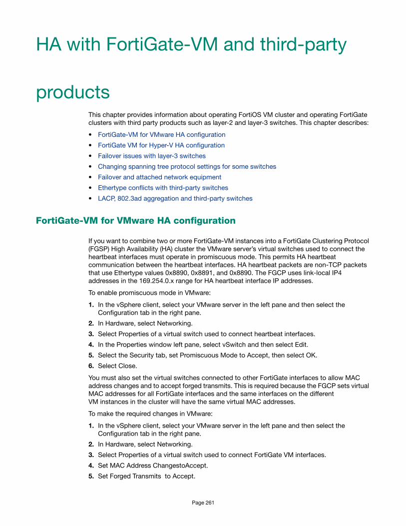
HA with FortiGate-VM and third-party
productsThis chapter provides information about operating FortiOS VM cluster and operating FortiGate clusters with third party products such as layer-2 and layer-3 switches. This chapter describes:
• FortiGate-VM for VMware HA configuration
• FortiGate VM for Hyper-V HA configuration
• Failover issues with layer-3 switches
• Changing spanning tree protocol settings for some switches
• Failover and attached network equipment
• Ethertype conflicts with third-party switches
• LACP, 802.3ad aggregation and third-party switches
FortiGate-VM for VMware HA configuration
If you want to combine two or more FortiGate-VM instances into a FortiGate Clustering Protocol (FGSP) High Availability (HA) cluster the VMware server’s virtual switches used to connect the heartbeat interfaces must operate in promiscuous mode. This permits HA heartbeat communication between the heartbeat interfaces. HA heartbeat packets are non-TCP packets that use Ethertype values 0x8890, 0x8891, and 0x8890. The FGCP uses link-local IP4 addresses in the 169.254.0.x range for HA heartbeat interface IP addresses.
To enable promiscuous mode in VMware:
1. In the vSphere client, select your VMware server in the left pane and then select the Configuration tab in the right pane.
2. In Hardware, select Networking.
3. Select Properties of a virtual switch used to connect heartbeat interfaces.
4. In the Properties window left pane, select vSwitch and then select Edit.
5. Select the Security tab, set Promiscuous Mode to Accept, then select OK.
6. Select Close.
You must also set the virtual switches connected to other FortiGate interfaces to allow MAC address changes and to accept forged transmits. This is required because the FGCP sets virtual MAC addresses for all FortiGate interfaces and the same interfaces on the different VM instances in the cluster will have the same virtual MAC addresses.
To make the required changes in VMware:
1. In the vSphere client, select your VMware server in the left pane and then select the Configuration tab in the right pane.
2. In Hardware, select Networking.
3. Select Properties of a virtual switch used to connect FortiGate VM interfaces.
4. Set MAC Address ChangestoAccept.
5. Set Forged Transmits to Accept.
Page 261

FortiGate VM for Hyper-V HA configuration
Promiscuous mode and support for MAC address spoofing is required for FortiGate-VM for Hyper-V to support FortiGate Clustering Protocol (FGCP) high availability (HA). By default the FortiGate-VM for Hyper-V has promiscuous mode enabled in the XML configuration file in the FortiGate-VM Hyper-V image. If you have problems with HA mode, confirm that this is still enabled.
In addition, because the FGCP applies virtual MAC addresses to FortiGate data interfaces and because these virtual MAC addresses mean that matching interfaces of different FortiGate-VM instances will have the same virtual MAC addresses you have to configure Hyper-V to allow MAC spoofing. But you should only enable MAC spoofing for FortiGate-VM data interfaces. You should not enable MAC spoofing for FortiGate HA heartbeat interfaces.
With promiscuous mode enabled and the correct MAC spoofing settings you should be able to configure HA between two or more FortiGate-VM for Hyper-V instances.
Troubleshooting layer-2 switches
Issues may occur because of the way an HA cluster assigns MAC addresses to the primary unit. Two clusters with the same group ID cannot connect to the same switch and cannot be installed on the same network unless they are separated by a router.
Forwarding delay on layer 2 switches
You must ensure that if there is a switch between the FortiGate HA cluster and the network its is protecting and the switch has a forwarding delay (even if spanning tree is disabled) when one of its interfaces is activated then the forwarding delay should be set as low as possible. For example, some versions of Cisco IOS have a forwarding delay of 15 seconds even when spanning tree is disabled. If left at this default value then TCP session pickup can fail because traffic is not forwarded through the switch on HA failover.
Failover issues with layer-3 switches
After a failover, the new primary unit sends gratuitous ARP packets to refresh the MAC forwarding tables of the switches connected to the cluster. If the cluster is connected using layer-2 switches, the MAC forwarding tables (also called arp tables) are refreshed by the gratuitous ARP packets and the switches start directing packets to the new primary unit.
In some configurations that use layer-3 switches, after a failover, the layer-3 switches may not successfully re-direct traffic to the new primary unit. The possible reason for this is that the layer-3 switch might keep a table of IP addresses and interfaces and may not update this table for a relatively long time after the failover (the table is not updated by the gratuitous ARP packets). Until the table is updated, the layer-3 switch keeps forwarding packets to the now failed cluster unit. As a result, traffic stops and the cluster does not function.
As of the release date of this document, Fortinet has not developed a workaround for this problem. One possible solution would be to clear the forwarding table on the layer-3 switch.
The config system ha link-failed-signal command described in “Updating MAC forwarding tables when a link failover occurs” on page 223 can be used to resolve link failover issues similar to those described here.
Fortinet Technologies Inc. Page 262 FortiOS™ Handbook - High Availability for FortiOS 5.0

Changing spanning tree protocol settings for some switches
Configuration changes may be required when you are running an active-active HA cluster that is connected to a switch that operates using the spanning tree protocol. For example, the following spanning tree parameters may need to be changed:
For an active-active HA cluster to be compatible with the spanning tree algorithm, the FGCP requires that the sum of maximum age and forward delay should be less than 20 seconds. The maximum age and forward delay settings are designed to prevent layer 2 loops. If there is no possibility of layer 2 loops in the network, you could reduce the forward delay to the minimum value.
For some Dell 3348 switches the default maximum age is 20 seconds and the default forward delay is 15 seconds. In this configuration the switch cannot work with a FortiGate HA cluster. However, the switch and cluster are compatible if the maximum age is reduced to 10 seconds and the forward delay is reduced to 5 seconds.
Spanning Tree protocol (STP)
Spanning tree protocol is an IEEE 802.1 standard link management protocol that for media access control bridges. STP uses the spanning tree algorithm to provide path redundancy while preventing undesirable loops in a network that are created by multiple active paths between stations. Loops can be created if there are more than route between two hosts. To control path redundancy, STP creates a tree that spans all of the switches in an extended network. Using the information in the tree, the STP can force redundant paths into a standby, or blocked, state. The result is that only one active path is available at a time between any two network devices (preventing looping). Redundant links are used as backups if the initial link should fail. Without spanning tree in place, it is possible that two connections may be simultaneously live, which could result in an endless loop of traffic on the network.
Bridge Protocol Data Unit (BPDU)
BPDUs are spanning tree data messages exchanged across switches within an extended network. BPDU packets contain information on ports, addresses, priorities and costs and ensure that the data ends up where it was intended to go. BPDU messages are exchanged across bridges to detect loops in a network topology. The loops are then removed by shutting down selected bridge interfaces and placing redundant switch ports in a backup, or blocked, state.
Failover and attached network equipment
It normally takes a cluster approximately 6 seconds to complete a failover. However, the actual failover time may depend on how quickly the switches connected to the cluster interfaces accept the cluster MAC address update from the primary unit. If the switches do not recognize
Maximum Age
The time that a bridge stores the spanning tree bridge control data unit (BPDU) before discarding it. A maximum age of 20 seconds means it may take 20 seconds before the switch changes a port to the listening state.
Forward Delay
The time that a connected port stays in listening and learning state. A forward delay of 15 seconds assumes a maximum network size of seven bridge hops, a maximum of three lost BPDUs and a hello-interval of 2 seconds.
Fortinet Technologies Inc. Page 263 FortiOS™ Handbook - High Availability for FortiOS 5.0

and accept the gratuitous ARP packets and update their MAC forwarding table, the failover time will increase.
Also, individual session failover depends on whether the cluster is operating in active-active or active-passive mode, and whether the content of the traffic is to be virus scanned. Depending on application behavior, it may take a TCP session a longer period of time (up to 30 seconds) to recover completely.
Ethertype conflicts with third-party switches
Some third-party network equipment may use packets with Ethertypes that are the same as the ethertypes used for HA heartbeat packets. For example, Cisco N5K/Nexus switches use Ethertype 0x8890 for some functions. When one of these switches receives Ethertype 0x8890 heartbeat packets from an attached cluster unit, the switch generates CRC errors and the packets are not forwarded. As a result, FortiGate units connected with these switches cannot form a cluster.
In some cases, if the heartbeat interfaces are connected and configured so regular traffic flows but heartbeat traffic is not forwarded, you can change the configuration of the switch that connects the HA heartbeat interfaces to allow level2 frames with Ethertypes 0x8890, 0x8893, and 0x8891 to pass.
You can also use the following CLI commands to change the Ethertypes of the HA heartbeat packets:
config system ha
set ha-eth-type <ha_ethertype_4-digit_hex>
set hc-eth-type <hc_ethertype_4-digit_hex>
set l2ep-eth-type <l2ep_ethertype_4-digit_hex>
end
For more information, see “Heartbeat packet Ethertypes” on page 197.
LACP, 802.3ad aggregation and third-party switches
If a cluster contains 802.3ad aggregated interfaces you should connect the cluster to switches that support configuring multiple Link Aggregation (LAG) groups.
The primary and subordinate unit interfaces have the same MAC address, so if you cannot configure multiple LAG groups a switch may place all interfaces with the same MAC address into the same LAG group; disrupting the operation of the cluster.
You can change the FortiGate configuration to prevent subordinate units from participating in LACP negotiation. For example, use the following command to do this for an aggregate interface named Port1_Port2:
config system interface
edit Port1_Port2
set lacp-ha-slave disable
end
This configuration prevents the subordinate unit interfaces from sending or receiving packets. Resulting in the cluster not being able to operate in active-active mode. As well, failover may be slower because after a failover the new primary unit has to perform LACP negotiation before being able to process network traffic.
For more information, see “Example: HA and 802.3ad aggregated interfaces” on page 88.
Fortinet Technologies Inc. Page 264 FortiOS™ Handbook - High Availability for FortiOS 5.0

VRRP
A Virtual Router Redundancy Protocol (VRRP) configuration can be used as a high availability solution to make sure that a network maintains connectivity with the Internet (or with other networks) even if the default router for the network fails. Using VRRP, if a router or a FortiGate unit fails all traffic to this router transparently fails over to another router or FortiGate unit that takes over the role of the router or FortiGate unit that failed. If the failed router or FortiGate unit is restored, it will once again take over processing traffic for the network. VRRP is described by RFC 3768.
Figure 33:Example VRRP configuration
To configure VRRP you create a VRRP group that contains two or more routers. Some or all of these routers can be FortiGate units. You can include different FortiGate models in the same VRRP group. The group members are configured to be the master router and one or more backup routers of the VRRP group. The network directs all traffic to the master’s IP address and MAC address. If the master fails, VRRP dynamically shifts packet forwarding to a backup router. VRRP provides this redundancy without user intervention or additional configuration to any of the devices on the network.
The VRRP redundancy scheme means that devices on the network keep a single IP address for the default gateway and this IP address maps to a well-known virtual MAC address. If the VRRP master fails, one of the backup units becomes the new master and acquires virtual IP and MAC addresses that match the addresses of the master. The network then automatically directs all traffic to the backup unit. VRRP uses the broadcast capabilities of Ethernet networks. A long as one of the routers in a VRRP group is running, ARP requests for the default gateway IP address always receive replies. Additionally, hosts can send packets outside their subnet without interruption.
FortiGate units support VRRP and can be quickly and easily integrated into a network that has already deployed a group of routers using VRRP. You can also create a new VRRP configuration consisting of a FortiGate unit acting as a VRRP master with one or more VRRP-compatible routers acting as backup routers. Some or all of those backup routers can be FortiGate units.
During normal operation the VRRP master unit sends VRRP advertisement messages to the backup units. A backup unit will not attempt to become a master unit while it is receiving these messages. When a FortiGate unit operating as a VRRP master fails, a backup unit takes its place and continues processing network traffic. The backup unit assumes the master unit has
InternalNetwork
FortiGate unitand VRRP compatible
Router in aVRRP group
LAN
Page 265

failed if it stops receiving the advertisement messages from the master unit. The backup unit with the highest priority becomes the new master unit after a short delay. During this delay the new master unit sends gratuitous ARPs to the network to map the virtual router IP address it its MAC address. As a result, all packets sent to the default route IP address are sent the new master unit. If the backup unit is a FortiGate unit, the network continues to benefit from FortiOS security features. If the backup unit is a router, after a failure traffic will continue to flow, but FortiOS security features will be unavailable until the FortiGate unit is back on line.
During a VRRP failover, as the backup unit starts to forward traffic it will not have session information for all of the failed over in-progress sessions. If the backup unit is operating as a normal FortiGate unit it will not be able to forward this traffic because of the lack of session information. To resolve this problem, immediately after a failover and for a short time as its taking over traffic processing, the backup unit operates with asymmetric routing enabled. This allows the backup unit to re-create all of the in-progress sessions and add them to the session table. While operating with asymmetric routing enabled, the backup unit cannot apply security functions. When the start-time ends the backup unit disables asymmetric routing and returns to normal operation including applying security functions.
Adding a VRRP virtual router to a FortiGate interface
Use the following command to add a VRRP virtual router to the port10 interface of a FortiGate unit. This VRRP virtual router has a virtual router ID of 200, uses IP address 10.31.101.200 and has a priority of 255. Since this is the highest priority this interface is configured to be the master of the VRRP group with ID number 200.
config system interface
edit port10
config vrrp
edit 200
set vrip 10.31.101.200
set priority 255
end
end
VRRP virtual MAC address
The VRRP virtual MAC address (or virtual router MAC address) is a shared MAC address adopted by the VRRP master. If the master fails the same virtual MAC master fails over to the new master. As a result, all packets for VRRP routers can continue to use the same virtual MAC address. You must enable the VRRP virtual MAC address feature on all members of a VRRP group.
Each VRRP router is associated with its own virtual MAC address. The last part of the virtual MAC depends on the VRRP virtual router ID using the following format:
00-00-5E-00-01-<VRID_hex>
Where <VRID_hex> is the VRRP virtual router ID in hexadecimal format in internet standard bit-order. For more information about the format of the virtual MAC see RFC 3768.
Some examples:
• If the VRRP virtual router ID is 10 the virtual MAC would be 00-00-5E-00-01-0a.
• If the VRRP virtual router ID is 200 the virtual MAC would be 00-00-5E-00-01-c8.
The VRRP virtual MAC address feature is disabled by default. Wen you enable the feature on a FortiGate interface, all of the VRRP routers added to that interface use their own VRRP virtual MAC address. Each virtual MAC address will be different because each virtual router has its own ID.
Fortinet Technologies Inc. Page 266 FortiOS™ Handbook - High Availability for FortiOS 5.0

Use the following command to enable the VRRP virtual MAC address on the port2 interface:
config system interface
edit port2
set vrrp-virtual-mac enable
end
end
The port2 interface will now accept packets sent to the MAC addresses of the VRRP virtual routers added to this interface.
Using the VRRP virtual MAC address can improve network efficiency especially on large and complex LANs because when a failover occurs devices on the LAN do not have to learn a new MAC address for the new VRRP router.
If the VRRP virtual MAC address feature is disabled, the VRRP group uses the MAC address of the master. In the case of a FortiGate VRRP virtual router this is the MAC address of the FortiGate interface that the VRRP virtual routers are added to. If a master fails, when the new master takes over it sends gratuitous ARPs to associate the VRRP virtual router IP address with the MAC address of the new master (or the interface of the FortiGate unit that has become the new master). If the VRRP virtual MAC address is enabled the new master uses the same MAC address as the old master.
Configuring VRRP
To configure VRRP you must configure two or more FortiGate interfaces or routers with the same virtual router ID and IP address. Then these FortiGate units or routers can automatically join the same VRRP group. You must also assign priorities to each of the FortiGate units or routers in the VRRP group. One of the FortiGate units or routers must have the highest priority to become the master. The other FortiGate units or routers in the group are assigned lower priorities and become backup units. All of the units in the VRRP group should have different priorities. If the master unit fails, VRRP automatically fails over to the remaining unit in the group with the highest priority.
You configure VRRP from the FortiGate CLI by adding a VRRP virtual router to a FortiGate interface. You can add VRRP virtual routers to multiple FortiGate interfaces and you can add more than one virtual router to the same interface.
Example VRRP configuration: two FortiGate units in a VRRP group
This example includes a VRRP group consisting of two FortiGate units that connect an internal network to the Internet. As shown in Figure 34, the internal network’s default route is 10.31.101.120.
The FortiGate port2 interfaces connect to the internal network. A VRRP virtual router is added to each FortiGate unit’s port2 interface. The virtual router IP address is 10.31.101.120 (the internal network’s default route) and the virtual router’s ID is 5. The VRRP priority of the master unit is set to 255 and the VRRP priority of the backup unit is 50. The port2 interface of each FortiGate unit should have an IP address that is different from the virtual router IP address and the port2 interface IP addresses should be different from each other.
This example also includes enabling the VRRP virtual MAC address on both FortiGate unit port2 interfaces so that the VRRP group uses the VRRP virtual MAC address.
Fortinet Technologies Inc. Page 267 FortiOS™ Handbook - High Availability for FortiOS 5.0

Figure 34:Example VRRP configuration with two FortiGate units
To configure the FortiGate units for VRRP
1. Select one of the FortiGate units to be the VRRP master and the other to be the backup unit.
2. From the master unit’s CLI, enter the following command to enable the VRRP virtual MAC address on the port2 interface and add the VRRP virtual router to the port2 interface:config system interface
edit port2
set vrrp-virtual-mac enable
config vrrp
edit 5
set vrip 10.31.101.120
set priority 255
end
end
3. From the backup unit’s CLI, enter the following command to enable the VRRP virtual MAC address on the port2 interface and add the VRRP virtual router to the port2 interface:config system interface
edit port2
set vrrp-virtual-mac enable
config vrrp
edit 5
set vrip 10.31.101.120
set priority 50
end
end
Example VRRP configuration: VRRP load balancing two FortiGate units and two VRRP groups
In this configuration two VRRP groups are involved. Each FortiGate unit participates in both of them. One FortiGate unit is the master of one group and the other FortiGate unit is the master of the other group. The network distributes traffic between two different default routes (10.31.101.120 and 10.31.101.130). One VRRP group is configured with one of the default route IP addresses and the other VRRP group get the other default route IP address. So during
InternalNetwork
FortiGateUnit
FortiGateUnit
ForttiGate
FFortiU
Default Route
10.31.101.120
VRRP Master
on port2
vrip = 10.31.101.120
vrid = 5
priority = 255
VRRP Backup
on port2
vrip = 10.31.101.120
vrid = 5
priority = 50
Fortinet Technologies Inc. Page 268 FortiOS™ Handbook - High Availability for FortiOS 5.0

normal operation both FortiGate units are processing traffic and the VRRP groups are used to load balance the traffic between the two FortiGate units.
If one of the FortiGate units fails, the remaining FortiGate unit becomes the master of both VRRP groups. The network sends all traffic for both default routes to this FortiGate unit. The result is a configuration that under normal operation load balances traffic between two FortiGate units, but if one of the FortiGate units fails, all traffic fails over to the unit that is still operating.
This example also includes enabling the VRRP virtual MAC address on both FortiGate unit port2 interfaces so that the VRRP groups use their VRRP virtual MAC addresses.
Figure 35:Example VRRP configuration with two FortiGate units and two VRRP groups
To configure the FortiGate units
1. Log into the CLI of FortiGate unit A.
2. Enter the following command to enable the VRRP virtual MAC address feature and add the VRRP groups to the port2 interface of FortiGate unit A:config system interface
edit port2
set vrrp-virtual-mac enable
config vrrp
edit 50 (32)
set vrip 10.31.101.120
set priority 255
next
edit 100 (64)
set vrip 10.31.101.130
set priority 50
end
end
3. Log into the CLI of FortiGate unit B.
InternalNetwork
FortiGate Unit A
VRRP Master
vrid = 5
vrip = 10.31.101.120
priority = 255
Default Route
10.31.101.120
Default Route
10.31.101.130FortiG
ate Unit B
VRRP Backup
vrid = 5
vrip = 10.31.101.120
priority = 50
VRRP Backup
vrid = 10
vrip = 10.31.101.130
priority = 50
VRRP Master
vrid = 10
vrip = 10.31.101.130
priority = 255
Fortinet Technologies Inc. Page 269 FortiOS™ Handbook - High Availability for FortiOS 5.0

4. Enter the following command to enable the VRRP virtual MAC address feature and add the VRRP groups to the port2 interface of FortiGate unit B:config system interface
edit port2
set vrrp-virtual-mac enable
config vrrp
edit 50
set vrip 10.31.101.120
set priority 50
next
edit 100
set vrip 10.31.101.130
set priority 255
end
end
Optional VRRP configuration settings
In addition to the basic configuration settings, you can change to the VRRP configuration to:
• Adjust the virtual router advertisement message interval between 1 and 255 seconds using the adv-interval option.
• Adjust the startup time using the start-time option. The default start time is 3 seconds and the range is 1 to 255 seconds. The start time is the maximum time that the backup unit waits between receiving advertisement messages from the master unit. If the backup unit does not receive an advertisement message during this time it assumes the master has failed and becomes the new master unit. In some cases the advertisement messages may be delayed. For example, some switches with spanning tree enabled may delay some of the advertisement message packets. If you find that backup units are attempting to become master units without the master unit failing, you can extend the start time to make sure the backup units wait long enough for the advertisement messages.
• Enable or disable individual virtual router configurations using the status option. Normally virtual router configurations are enabled but you can temporarily disable one if its not required.
• Enable or disable preempt mode using the preempt option. In preempt mode a higher priority backup unit can preempt a lower priority master unit. This can happen if a master has failed, a backup unit has become the master unit, and the failed master is restarted. Since the restarted unit will have a higher priority, if preempt mode is enabled the restarted unit will replace the current master unit. Preempt mode is enabled by default.
• Monitor the route to a destination IP address using the vrdst option.
Fortinet Technologies Inc. Page 270 FortiOS™ Handbook - High Availability for FortiOS 5.0
FortiGate Session Life Support Protocol (FGSP)
You can use the config system session-sync command to configure the FortiGate Session Life Support Protocol (FGSP) (previously called TCP session synchronization or standalone session synchronization) between two FortiGate units. The two FortiGate units must be the same model. The FGSP synchronizes both IPv4 and IPv6 TCP, UDP, ICMP, expectation, and NAT sessions. You can use this feature with external routers or load balancers configured to distribute or load balance sessions between two peer FortiGate units. If one of the peers fails, session failover occurs and active sessions fail over to the peer that is still operating. This failover occurs without any loss of data. As well, the external routers or load balancers will detect the failover and re-distribute all sessions to the peer that is still operating.
The FGSP can be used instead of FGCP HA to provide session synchronization between two peer FortiGate units. If the external load balancers direct all sessions to one peer the affect is similar to active-passive FGCP HA. If external load balancers or routers load balance traffic to both peers, the effect is similar to active-active FGCP HA. The load balancers should be configured so that all of the packets for any given session are processed by the same peer. This includes return packets.
In previous versions of FortiOS the FGSP was called TCP session synchronization or standalone session synchronization. However, the FGSP has been expanded to include configuration synchronization and session synchronization of connectionless sessions, expectation sessions, and NAT sessions.
You cannot configure FGSP HA when FGCP HA is enabled. However FGSP HA is compatible with VRRP.
FGSP or standalone session synchronization is not supported if the FortiGate units are running different firmware versions.
Page 271

Figure 36:FGSP HA
By default, FGSP synchronizes all IPv4 and IPv6 TCP sessions and also synchronizes the configuration of the FortiGate units.
You can optionally enable session pickup to synchronize connectionless (UDP and ICMP) sessions, expectation sessions, and NAT sessions. If you do not enable session pickup, the FGSP does not share session tables for the particular session type and sessions do not resume after a failover. All sessions that are interrupted by the failover and must be re-established at the application level. Many protocols can successfully restart sessions with little, or no, loss of data. Others may not recover easily. Enable session pickup for sessions that may be difficult to reestablish. Since session pickup requires FortiGate resources, only enable this feature for sessions that you need to have synchronized.
You can also optionally add filters to control which sessions are synchronized. You can add filters to only synchronize packets from specified source and destination addresses, specified source and destination interfaces, and specified services.
Load balancing and session failover is done by external routers or load balancers instead of by the FGSP. The FortiGate units just perform session synchronization to support session failover.
Synchronizing the configuration
The FGSP also includes configuration synchronization, allowing you to make configuration changes once for both FortiGate units instead of requiring you to make duplicate configuration changes on each FortiGate unit. Settings that identify the FortiGate unit to the network, for example, interface IP addresses and BGP neighbor settings, are not synchronized so each FortiGate unit maintains its identity on the network.
By default configuration synchronization is disabled. You can use the following command to enable it.
config system ha
set standalone-config-sync enable
end
Router orLoad Balancer
Router orLoad BalancerInternal
Network
FortiGate unit
FortiGate unit
Sychronization
Link
LAN
Sy
Foation
k
Fortinet Technologies Inc. Page 272 FortiOS™ Handbook - High Availability for FortiOS 5.0

Synchronizing UDP and ICMP (connectionless) sessions
In many configurations, due to their non-stateful nature, UDP and ICMP sessions don't need to be synchronized to naturally failover. However, if its required you can configure the FGSP to synchronize UDP and ICMP sessions by entering the following command:
config system ha
set session-pickup enable
set session-pickup-connectionless enable
end
Synchronizing NAT sessions
By default, NAT session are not synchronized. However, the FGSP can synchronize NAT session if you enter the following command:
config system ha
set session-pickup enable
set session-pickup-nat enable
end
However, if you want NAT sessions to resume after a failover you should not configure NAT to use the destination interface IP address since the FGSP FortiGate units have different IP addresses. With this configuration, after a failover all sessions that include the IP addresses of interfaces on the failed FortiGate unit will have nowhere to go since the IP addresses of the failed FortiGate unit will no longer be on the network.
Instead, in an FGSP configuration, if you want NAT sessions to failover you should use IP pools with the type set to overload (which is the default IP pool type). For example:
config firewall ippool
edit FGSP-pool
set type overload
set startip 172.20.120.10
set endip 172.20.120.20
end
Then when you configure NAT firewall policies, turn on NAT and select to use dynamic IP pool and select the IP Pool that you added. Add the same IP pools and firewall policies to both FortiGate units.
Synchronizing expectation (asymmetric) sessions
By default, expectation sessions (or asymmetric sessions) are not synchronized. Normally, session synchronization cannot be asymmetric because it is stateful. So all of the packets of a given session must be processed on the same peer. This includes return packets.
However, if you have an asymmetric routing configuration, you can enter the following command to synchronize asymmetric sessions by dynamically detecting asymmetric sessions and disabling anti-reply for these sessions.
config system ha
set session-pickup enable
set session-pickup-expectation enable
end
Fortinet Technologies Inc. Page 273 FortiOS™ Handbook - High Availability for FortiOS 5.0

The FGSP enforces firewall policies for asymmetric traffic, including cases where the TCP 3-way handshake is split between two FortiGates. For example, FGT-A receives the TCP-SYN, FGT-B receives the TCP-SYN-ACK, and FGT-A receives the TCP-ACK. Under normal conditions a firewall will drop this connection since the 3-way handshake was not seen by the same firewall. However two FortiGates with FGSP configured will be able to properly pass this traffic since the firewall sessions are synchronized.
If traffic will be highly asymmetric, as described above, the following command must be enabled on both FortiGates.
config system ha
set session-pickup enable
set session-pickup-expectation enable
end
This asymmetric function can also work with connectionless UDP and ICMP traffic. The following command needs to enabled on both FortiGates.
config system ha
set session-pickup enable
set session-pickup-connectionless enable
end
Synchronizing asymmetric traffic can be very useful in situations where multiple Internet connections from different ISPs are spread across two FortiGates. Since it is typically not possible to guarantee Internet bound traffic leaving via an ISP will return using the exact same ISP, the FGSP provides critical firewall functions in this situation.
The FGSP also has applications in virtualized computing environments where virtualized hosts move between data centers. The firewall session synchronization features of FGSP allow for more flexibility than in traditional firewalling functions.
UTM Flow-based Inspection and Asymmetric Traffic
UTM inspection (flow or proxy based) for a session is not expected to work properly if the traffic in the session is balanced across more than one FortiGate in either direction. Flow-based UTM should be used in FGSP deployments.
For an environment where traffic is symmetric, UTM can be used with the following limitations:
• No session synchronization for the sessions inspected using proxy-based UTM. Sessions will drop and need to be reestablished after data path failover.
• Sessions with flow-based UTM will failover; however, inspection of failed over sessions after the failover may not work.
A single FortiGate must see both the request and reply traffic for UTM inspection to function correctly. For environments where asymmetric traffic is expected, UTM inspection should not be used.
Notes and limitations
FGSP HA has the following limitations:
• The FGSP is a global configuration option. As a result you can only add one service to a filter configuration. You cannot add custom services or service groups even if virtual domains are not enabled.
Fortinet Technologies Inc. Page 274 FortiOS™ Handbook - High Availability for FortiOS 5.0

• You can only add one filter configuration to a given FGSP configuration. However, you can add multiple filters by adding multiple identical FGSP configurations, each one with a different filter configuration.
• Sessions accepted by security policies with UTM options configured are not synchronized.
• FGSP HA is configured from the CLI.
• FGSP HA is available for FortiGate units or virtual domains operating in NAT/Route or Transparent mode. NAT sessions are not synchronized in either mode (unless NAT synchronization is enabled as described in “Synchronizing NAT sessions” on page 273). In NAT/Route mode, only sessions for route mode security policies are synchronized. In Transparent mode, only sessions for normal Transparent mode policies are synchronized.
• FGSP HA is supported for traffic on physical interfaces, VLAN interfaces, zones, aggregate interfaces, and NPx (NP4, NP6 etc.) accelerated interfaces. The FGSP has not been tested for inter-vdom links, between HA clusters, and for redundant interfaces.
• The names of the matching interfaces, including VLAN interfaces, aggregate interfaces and so on, must be the same on both peers.
Configuring FGSP HA
You configure FGSP HA separately for each virtual domain to be synchronized. If virtual domain configuration is not enabled, you configure FGSP HA for the root virtual domain. When virtual domain configuration is enabled and you have added virtual domains you configure FGSP HA for each virtual domain to be synchronized. You don’t have to synchronize all virtual domains.
You must configure FGSP HA and network settings on both peers. Once you establish the initial configuration, the configurations of both FortiGate units are synchronized so when you change the configuration of one, the changes are synchronized to the other.
On each FortiGate unit, configuring FGSP HA consists of selecting the virtual domains to be synchronized using the syncvd field, selecting the virtual domain on the other peer that receives the synchronization packets using the peervd field, and setting the IP address of the interface in the peer unit that receives the synchronization packets using the peerip field. The interface with the peerip must be in the peervd virtual domain.
The syncvd and peervd settings must be the same on both peers. However, the peerip settings will be different because the peerip setting on the first peer includes the IP address of an interface on the second peer. And the peerip setting on the second peer includes the IP address of an interface on the first peer.
For FGSP HA to work properly all synchronized virtual domains must be added to both peers. The names of the matching interfaces in each virtual domain must also be the same; this includes the names of matching VLAN interfaces. Note that the index numbers of the matching interfaces and VLAN interfaces can be different. Also the VLAN IDs of the matching VLAN interfaces can be different.
For a configuration example, see “Basic example configuration” on page 276.
Configuring the session synchronization link
When FGSP HA is operating, the peers share session information over an Ethernet link between the peers similar to an HA heartbeat link. Usually you would use the same interface on each peer for session synchronization. You should connect the session synchronization interfaces directly without using a switch or other networking equipment. For FortiGate-5000 systems you can use a backplane interface as the session synchronization link.
Fortinet Technologies Inc. Page 275 FortiOS™ Handbook - High Availability for FortiOS 5.0

You can use different interfaces on each peer for session synchronization links. Also, if you have multiple sessions synchronization configurations, you can have multiple links between the peers. In fact if you are synchronizing a lot of sessions, you may want to configure and connect multiple session synchronization links to distribute session synchronization traffic to these multiple links.
You cannot configure backup session synchronization links. Each configuration only includes one session synchronization link.
The session synchronization link should always be maintained. If session synchronization communication is interrupted and a failure occurs, sessions will not failover and data could be lost.
Session synchronization traffic can use a considerable amount of network bandwidth. If possible, session synchronization link interfaces should only be used for session synchronization traffic and not for data traffic.
Basic example configuration
The following configuration example shows how to configure basic FGSP HA for the two peer FortiGate units shown in Figure 37 on page 276. The host names of peers are peer_1 and peer_2. Both peers are configured with two virtual domains: root and vdom_1. All sessions processed by vdom_1 are synchronized. The synchronization link interface is port3 which is in the root virtual domain. The IP address of port3 on peer_1 is 10.10.10.1. The IP address of port3 on peer_2 is 10.10.10.2.
Also on both peers, port1 and port2 are added to vdom_1. On peer_1 the IP address of port1 is set to 192.168.20.1 and the IP address of port2 is set to 172.110.20.1. On peer_2 the IP address of port1 is set to 192.168.20.2 and the IP address of port2 is set to 172.110.20.2.
Figure 37:Example FGSP HA network configuration
To configure FGSP HA
1. Configure the load balancer or router to send all sessions to peer_1.
2. Configure the load balancer or router to send all traffic to peer_2 if peer_1 fails.
InternalNetwork
Router or
Load Balancer
Session and
Configuration
Synchronization
Link
Port1
Port3
10.10.10.2
Port3
10.10.10.1
Vdom_1
root
root
Port2
Port1Vdom_1
Port2
Router or
Load Balancer
Fortinet Technologies Inc. Page 276 FortiOS™ Handbook - High Availability for FortiOS 5.0

3. Use normal FortiGate configuration steps on peer_1:
• Enable virtual domain configuration.
• Add the vdom_1 virtual domain.
• Add port1 and port2 to the vdom_1 virtual domain and configure these interfaces.
• Set the IP address of port1 to 192.168.20.1.
• Set the IP address of port2 to 172.110.20.1.
• Set the IP address of port3 to 10.10.10.1.
• Add route mode security policies between port1 and port2 to vdom_1.
4. Enter the following commands to configure session synchronization for peer_1config system session-sync
edit 1
set peerip 10.10.10.2
set peervd root
set syncvd vdom_1
end
5 Use normal FortiGate configuration steps on peer_2:
• Enable virtual domain configuration.
• Add the vdom_1 virtual domain.
• Add port1 and port2 to the vdom_1 virtual domain and configure these interfaces.
• Set the IP address of port1 to 192.168.20.2.
• Set the IP address of port2 to 172.110.20.2.
• Set the IP address of port3 to 10.10.10.1.
• Add route mode security policies between port1 and port2 to vdom_1.
6. Enter the following command to configure session synchronization for peer_1config system session-sync
edit 1
set peerip 10.10.10.1
set peervd root
set syncvd vdom_1
end
Now that the FortiGate units are connected and configured their configurations are synchronized, so when you make a configuration change on one FortiGate unit it is synchronized to the other one.
To add filters
You can add a filter to this basic configuration if you only want to synchronize some TCP sessions. For example you can enter the following command to add a filter so that only HTTP sessions are synchronized:
config system session-sync
edit 1
config filter
set service HTTP
end
end
Fortinet Technologies Inc. Page 277 FortiOS™ Handbook - High Availability for FortiOS 5.0

You can also add a filter to control the source and destination addresses of the IPv4 packets that are synchronized. For example you can enter the following command to add a filter so that only sessions with source addresses in the range 10.10.10.100 to 10.10.10.200 are synchronized.
config system session-sync
edit 1
config filter
set srcaddr 10.10.10.100 10.10.10.200
end
end
You can also add a filter to control the source and destination addresses of the IPv6 packets that are synchronized. For example you can enter the following command to add a filter so that only sessions with destination addresses in the range 2001:db8:0:2::/64 are synchronized.
config system session-sync
edit 1
config filter
set dstaddr6 2001:db8:0:2::/64
end
end
To synchronize UDP and ICMP sessions
You enter the following command to add synchronization of UDP and ICMP sessions to this configuration:
config system ha
set session-pickup enable
set session-pickup-connectionless enable
end
To synchronize the configuration
Enter the following command to enable configuration synchronization.
config system ha
set standalone-config-sync enable
end
Verifying FGSP configuration and synchronization
You can use the following diagnose commands to verify that the FGSP and its synchronization functions are operating correctly.
Fortinet Technologies Inc. Page 278 FortiOS™ Handbook - High Availability for FortiOS 5.0

FGSP configuration summary and status
Enter the following command to display a summary of the FGSP configuration and synchronization status:
diagnose sys session sync
sync_ctx: sync_started=1, sync_tcp=1, sync_others=1,
sync_expectation=1, sync_redir=0, sync_nat=1.
sync: create=12:0, update=0, delete=0:0, query=14
recv: create=14:0, update=0, delete=0:0, query=12
ses pkts: send=0, alloc_fail=0, recv=0, recv_err=0 sz_err=0
nCfg_sess_sync_num=5, mtu=16000
sync_filter:
1: vd=0, szone=0, dzone=0, saddr=0.0.0.0:0.0.0.0, daddr=0.0.0.0:0.0.0.0,
sync_started=1 shows that synchronization is working. If this is set to 0 then something is not correct with session synchronization and synchronization has not been able to start because of it.
sync_tcp=1, sync_others=1, sync_expectation=1, and sync_nat=1 show that the FGSP has been configured to synchronize TCP, connectionless, asymmetric, and NAT sessions.
sync: create=12:0 and recv: create=14:0 show that this FortiGate has synchronized 12 sessions to its peer and has received 14 sessions from its peer.
sync_filter shows the configured FGSP filter. In this case no filter has been created so all sessions are synchronized.
vd=0 indicates that root VDOM sessions are synchronized.
Fortinet Technologies Inc. Page 279 FortiOS™ Handbook - High Availability for FortiOS 5.0

Verifying that sessions are synchronized
Enter the command diagnose sys session list to display information about the sessions being processed by the FortiGate. In the command output look for sessions that should be synchronized and make sure they contain output lines that include synced (for example, state=log may_dirty ndr synced) to confirm that they are being synchronized by the FGSP.
diagnose sys session list
session info: proto=6 proto_state=05 duration=469 expire=0 timeout=3600
flags=00000000 sockflag=00000000 sockport=21 av_idx=0 use=4
origin-shaper=
reply-shaper=
per_ip_shaper=
ha_id=0 policy_dir=0 tunnel=/
state=log may_dirty ndr synced
statistic(bytes/packets/allow_err): org=544/9/1 reply=621/7/0 tuples=2
orgin->sink: org pre->post, reply pre->post dev=46->45/45->46
gwy=10.2.2.1/10.1.1.1
hook=pre dir=org act=noop 192.168.1.50:45327->172.16.1.100:21(0.0.0.0:0)
hook=post dir=reply act=noop 172.16.1.100:21->192.168.1.50:45327(0.0.0.0:0)
pos/(before,after) 0/(0,0), 0/(0,0)
misc=0 policy_id=1 id_policy_id=0 auth_info=0 chk_client_info=0 vd=0
serial=00002deb tos=ff/ff ips_view=1 app_list=2000 app=16427
dd_type=0 dd_mode=0
per_ip_bandwidth meter: addr=192.168.1.50, bps=633
Fortinet Technologies Inc. Page 280 FortiOS™ Handbook - High Availability for FortiOS 5.0

Configuring FRUP
The FortiGate Redundant UTM Protocol (FRUP) provides similar redundancy to FGCP full mesh HA in a single unified design that includes redundant switching and routing. FRUP is available on the FortiGate-100D and will be expanded to other models in future releases.
A FRUP cluster consists of 2 (and only 2) identical FortiGate-100D units that have dual redundant links to all connected devices and networks and can include redundant FortiAP units. Connections to the Internet normally use the wan1 and wan2 interfaces for redundant connections. Connections to internal networks and servers use redundant connections to FortiGate-100D switch ports. FRUP uses the FortiGate-100D switch ports for full mesh HA instead of external redundant switches.
Each device or network has a default active connection to one of the FortiGate units and a default backup connection to the other. Ideally, the default active and backup connections should balance traffic between the FortiGate units in the cluster so that both FortiGate units are processing the same amount of traffic.
FRUP uses virtual IPs and virtual MACs so that when a failover occurs, network devices do not have to learn new IP or MAC addresses. FRUP also synchronizes the configuration between the units in the cluster.
Use the following CLI command on both FortiGate-100D units to configure FRUP.
config system ha
set hbdev "ha1" 50 "ha2" 100
set override disable
set priority 128
set frup enable
config frup-settings
set active-interface "wan2"
set active-switch-port 14
set backup-interface "wan1"
end
end
Both units must have the same heartbeat device configuration and have FRUP enabled to form a FRUP cluster. Active interface and switch ports must be complementary according to your configuration (see the following example).
Page 281

FRUP configuration example
This example includes the following:
• Two FortiGate-100D units (FGT-A and FGT-B)
• HA1 and HA2 for redundant HA heartbeat connectivity between FGT-1 and FGT-2
• Dual gateways (router1 and router2):
• FGT-A has an active connection from WAN1 to router-1 and a backup connection from WAN2 to router-2
• FGT-B has an active connection from WAN2 to router-2 and a backup connection from WAN1 to router-1
• Dual connections to the internal network and an internal server:
• FGT-A has an active connection to an internal server using switch port 16 and a backup connection to the internal network using switch port 14
• FGT-B has a backup connection to an internal server using switch port 16 and an active connection to the internal network using switch port 14
• FortiGate interfaces use virtual IP addresses and pseudo-MAC physical addresses, all devices continue to send to the same IP/Mac and don't need to re-learn after a failover
• Both FortiGate units will handle and process traffic
• Backup links are normally administratively down
• Sessions and the FortiGate configuration are synchronized between the cluster units
Figure 38:Example FRUP configuration
Configuring FGT-A
Change the host name to FGT-A. Set up FGT-A with dual redundant internet links using WAN1 and WAN2. Set WAN1 and WAN2 interfaces to use static addressing and set both static routes to same priority and distance.
InternalNetwork
192.168.1.114
Router-1
Router-2
Switch
Switch
port 14
(backup)
Switch
port16
(active)
Switch
port 16
(backup)
WAN1
(active)
WAN2
(backup)
FGT-A
FGT-B
WAN2
(active)
WAN1
(backup)
Switch
port 14
(active)
Dual HA lin
ksServer
192.268.1.200
S
Fortinet Technologies Inc. Page 282 FortiOS™ Handbook - High Availability for FortiOS 5.0

From CLI enter the following command:
config system ha
set hbdev "ha1" 50 "ha2" 100
set override disable
set priority 255
set frup enable
config frup-settings
set active-interface "wan1"
set active-switch-port 16
set backup-interface "wan2"
end
end
Configuring FGT-B
Use the same firmware version as FGT-A and set the FortiGate unit to factory defaults. Change the host name to FGT-B.
From CLI enter the following command:
config system ha
set hbdev "ha1" 50 "ha2" 100
set override disable
set priority 128
set frup enable
config frup-settings
set active-interface "wan2"
set active-switch-port 14
set backup-interface "wan1"
end
end
Connecting, testing and operating the FRUP cluster
Connect to the FortiGate-100D units to the network as shown in the diagram and power them on. The FortiGate-100D units should find each other and form a cluster.
Traffic from the server (IP: 192.168.1.200) connected to port16 should pass through FGT-A (since port16 is the active-switch-port in FGT-A) and to the Internet using WAN1 (since WAN1 is the active-interface in FGT-A).
Run a sniffer on both FortiGate units using the following command:
diagnose sniffer packet any ‘icmp’ 4
interfaces=[any]
filters=[icmp]
Then run a ping to 4.2.2.2 from the server. The sniffer should show results similar to the following:
Fortinet Technologies Inc. Page 283 FortiOS™ Handbook - High Availability for FortiOS 5.0

Traffic initiating from a host on the internal network (for example, IP: 192.168.1.114) connected to port14 should flow through FGT-B (since port14 is the active-switch-port in FGT-B) to the Internet using WAN2 (since WAN2 is FGT-B’s active interface).
Run the same sniffer on both FortiGate units and then run a ping to 74.125.226.1 from the internal network. The sniffer should show results similar to the following:
Fortinet Technologies Inc. Page 284 FortiOS™ Handbook - High Availability for FortiOS 5.0

Shutdown FGT-A.
Traffic from the internal network should be handled by FGT-B using WAN1 and WAN2 interfaces:
To re-establish the cluster after a failover you need to restart both FortiGate-100D units. Just re-starting FGT-A may not bring the cluster back online.
Fortinet Technologies Inc. Page 285 FortiOS™ Handbook - High Availability for FortiOS 5.0

Index
Numerics802.3ad
aggregate interface 88802.3ad aggregate interface
full mesh HA 140HA MAC addresses 88port monitoring 88
Aa-a
load balance schedule 248active sessions
HA statistics 172active-active
best practice 43device failover 245link failover 245load balancing 29, 244network processor accelerated interfaces 247operation mode 29redundant interfaces 101session failover 245UTM sessions continue after a failover 236
active-passivedevice failover 28failover 190LACP 89link failover 28operating mode 28
active-passive moderedundant interfaces 101
adding, configuring definingHA 49port monitoring (HA) 50
ADM 247advertisement message
adjusting the interval 270advertisement messages
VRRP 265age
age difference margin 33changing the age difference margin 33displaying cluster unit age 34primary unit selection 33reset the cluster age 35resetting cluster unit age 35
age difference margin 33changing 33
aggregate interfacebest practice 44HA MAC addresses 88interface monitoring 88
alert emailHA 177
AMChard disk 43
ARPgratuitous 200
arp table 223, 262arps
CLI command 201gratuitous 201
arps-intervalCLI command 201
attached network equipmentfailover 236
authenticationheartbeat 199
Bback to HA monitor
HA statistics 172backup
cluster configuration 176backup unit 22
See Also subordinate unit 22best practice 45BGP
graceful restart 216BPDU
message exchange 263bridge protocol data unit 263broken cluster unit
replacing 87busy
load balance 251
CCB2 247CLI
session-pickup 194, 231CLI command
55, 60, 67, 71, 78, 81, 91, 95, 103, 107, 124, 129, 144, 148, 204
clusteradding a new FortiGate unit 86configuring in transparent mode 65connecting an HA cluster 27converting a standalone FortiGate unit 84definition 45distributed 43, 163operating 152replacing a failed cluster unit 87virtual cluster 117
Page 286

cluster configurationbackup 176restore 176troubleshoot
57, 63, 69, 76, 80, 84, 92, 98, 104, 109, 113,114, 145, 149
cluster member 168cluster members list 169priority 169role 169
cluster name 29cluster unit
connect to a cluster 185definition 45disconnect from a cluster 185getting information using SNMP 166, 167
getting cluster unit serial numbers 167getting serial numbers using SNMP 167SNMP get 166, 167
cluster units 22configuration
backup 176restore 176synchronization 207
configuration synchronization 192disabling 208
configuring a FortiGate unit for HA operation 25connected monitored interfaces
primary unit selection 32connecting a FortiGate HA cluster 27connectionless
session pickup 235console messages
synchronization fails 210CPU usage
HA statistics 172weight 251
cpu usageweighted load balancing 251
Ddead gateway detection 226debug
diagnose 213dedicated monitoring
interface 154delaying session pickup 232device
failure 191device failover 190, 192
active-active 245active-passive 28configuration synchronization 192definition 45HA heartbeat 192IPsec SA synchronization 192route synchronization 192virtual MAC address 192
device priority 174primary unit selection 31, 36subordinate unit 173
DHCP 42relay 42server 42
diagnosesys ha reset-uptime 35sys ha showcsum 213
diagnose debug 213diagnose hardware deviceinfo nic
55, 60, 67, 71, 78, 81, 91, 95, 103, 107, 124, 129, 144, 148
CLI command 205diagnose sys ha dump-by 34disconnecting a unit from a cluster
override 42distance between cluster units 43, 163distributed cluster 43, 163dynamic routing
failover 215
Eenable session pickup 231encryption
heartbeat 199execute
ha synchronize all 208execute formatlogdisk 164explicit web proxy 234
load balancing 244
FFA2 247failed cluster unit
replacing 87failover 30
active-passive 190and attached network equipment 236attached network equipment 263definition 45delayed 263device 190, 192dynamic routing 215enabling session failover 231GTP and HA session failover 235HA 22heartbeat 46issues with layer-3 switches 262link 47, 190, 219monitoring cluster units 177session 23, 191, 231subsecond 225
failover protection 117active-passive operating mode 28virtual clustering 117
Fortinet Technologies Inc. Page 287 FortiOS™ Handbook - High Availability for FortiOS 5.0

failuredefinition 45device 191link 191, 219multiple link failures 224
FB4 247FB8 247FDN 160FGCP
definition 46description 17
FGSP 18, 271filters 272
FGT_ha_adminHA administrator account 185
filequarantine 168
firewallload balancing 234
firmware upgradeHA 174
formatlogdisk 164formatting hard disks 164formatting log disks 164FortiAnalyzer 161FortiGate Cluster Protocol
description 17FortiGate Session Life Support Protocol 18, 271FortiGate unit
adding to a cluster 86converting from standalone to a cluster 84replacing a failed 87
FortiGate unit serial numberprimary unit selection 37
FortiGuard 160FortiGuard Antispam 160FortiGuard Antivirus 160FortiGuard Distribution Network 160FortiGuard Intrusion Protection 160FortiGuard Web Filtering 160forward delay
spanning tree parameter 263
forwardingMAC forwarding table 223, 262
FRUP 19FSM
hard disk 43full mesh 24
HA 139redundant HA heartbeat interfaces 140
full mesh HA 22, 139configuration example 141definition 46troubleshooting 151
GGARP 200geographical
distribution 43, 163get hardware nic
55, 60, 67, 71, 78, 81, 91, 95, 103, 107, 114, 124, 129, 144, 148, 204
get system performance status 163grace period
age difference margin 33changing 33
graceful restartBGP 216OSPF 216
gratuitous ARP packets 200gratuitous arps 201gratuitous-arps
CLI command 202group ID
changing 206HA configuration option 30virtual MAC address 206
group nameHA cluster name 29HA configuration option 29
group-idCLI command 206
GTPHA session failover 235
GTP UDPsession failover 235
Fortinet Technologies Inc. Page 288 FortiOS™ Handbook - High Availability for FortiOS 5.0

HHA 169
alert email 177changing firmware upgrade 175cluster member 169cluster members list 168configure weighted-round-robin weights 249configuring virtual clustering 121, 123, 128connect a cluster unit 185definition 17disconnect a cluster unit 185event log message 161FGT_ha_admin administrator account 185firmware upgrade 174full mesh and 802.3ad aggregate interfaces 140full mesh and redundant heartbeat interfaces 140full mesh HA configuration example 141GTP session failover 235hello state 162host name 169link failover scenarios 224log message 161manage individual cluster units 184manage logs for individual cluster units 161monitor cluster units for a failover 177SNMP and reserved management interface 155standby state 162states 162subordinate unit device priority 173subordinate unit host name 173VDOM partitioning 51viewing HA statistics 171virtual cluster 117virtual clustering 49virtual domains 117work state 162
HA group IDchanging 206
HA group name 29HA heartbeat 192
definition 46HA statistics
active sessions 172back to HA monitor 172CPU usage 172intrusion detected 173memory usage 172monitor 172network utilization 172refresh every 172serial no 172status 172total bytes 173total packets 172up time 172virus detected 172
HA virtual MAC addressdefinition 46
ha-eth-typeCLI command 197, 264
hard diskAMC 43FSM 43
hard disksformatting 164
hardwareget hardware nic command
55, 60, 67, 71, 78, 81, 91, 95, 103, 107, 124,129, 144, 148, 204
hardware revisionsignoring 112
hash map 196hb-interval 198hb-lost-threshold 198hc-eth-type
CLI command 197, 264heartbeat 192
authentication 199changing the heartbeat interval 198changing the hello state hold-down time 199changing the lost heartbeat threshold 198definition 46encryption 199modifying heartbeat timing 198
heartbeat devicedefinition 46
heartbeat failoverdefinition 46
heartbeat interface 21, 193best practice 44configuring 194priority 194selection 195virtual clustering 117
heartbeat interfaces 117hello state
changing the time to wait 199definition 46
hello state hold-down timechanging 199
helo-holddown 199high availability
definition 17, 46host name 174
best practice 43hostname
cluster members list 169HTTP multiplexing 234
load balancing 244HTTPS
load balancing 244hub
HA schedule 245
IICMP
session pickup 235IM
load balancing 244
Fortinet Technologies Inc. Page 289 FortiOS™ Handbook - High Availability for FortiOS 5.0

incrementalsynchronization 208
index 196interface
dedicated monitoring 154failover 219HA heartbeat 194heartbeat 21, 193monitor 219reserved management interface 154
interface indexhash map order 196
interface monitoring 45aggregate interfaces 88definition 46redundant interfaces 100
intervalchanging the heartbeat interval 198
intrusion detectedHA statistics 173
IP 245IP monitoring
remote 226IP port
HA schedule 245IPsec
SAs 218security associations 218
IPsec VPNload balancing 244
IPsec VPN SAsynchronization 192
IPv6session failover 234
Kkeyword 38
Ll2ep-eth-type
CLI command 197, 264L2TP 235LACP 88
active-passive HA mode 89LACPDU 89lacp-ha-slave
CLI keyword 89, 264LAG 88layer-2 switch
troubleshooting 262layer-3 switch
failover issues 262LDAP 159, 160Least-Connection
HA schedule 245link
failure 191multiple link failures 224
Link Aggregation Control Protocol 88
link failover 190, 219active-active 245active-passive 28aggregate interfaces 88definition 47not detected by high-end switches 223redundant interfaces 100
link failureremote 226
link-failed-signal 223CLI 224
load balanceaccording to loading 251cpu usage 251explicit web proxy 244how busy 251HTTP multiplexing 244HTTPS 244IM 244IPsec VPN 244memory usage 251P2P 244proxy UTM sessions 251schedule 248SSL offloading 244SSL VPN 244VoIP 244WAN optimization 244WCCP 244
load balancing 22, 23active-active 29, 244definition 47load-balance-all 244
load-balance-all 247best practice 43enabling 244
log diskformatting 164
log messageHA 161
log messagesHA 162
logging 161HA log messages 162
logsmanaging for individual cluster units 161
lost heartbeat thresholdchanging 198
MMAC
MAC forwarding table 223, 262MAC address
aggregate interfaces 88redundant interfaces 101virtual 200VRRP virtual 266
MAC forwarding tables 223, 262manage cluster units
HA 184
Fortinet Technologies Inc. Page 290 FortiOS™ Handbook - High Availability for FortiOS 5.0

management interfacereserved 154
master unitSee Also primary unit 22
maximum agespanning tree parameter 263
memory usageHA statistics 172weight 251weighted load balancing 251
MIBHA 164
monitorHA statistics 172interface 219port 219
monitored interfacedefinition 47primary unit selection 32
NNAT/Route mode
general configuration steps 53, 89, 101, 122HA network topology 53reserved management interface 155web-based manager configuration steps
54, 58, 66, 70, 77, 80NAT64
session failover 234NAT66
session failover 234network
train 200network equipment
failover time 263network processor accelerated interfaces
accelerate active-active HA 247network topology
NAT/Route mode HA 53network utilization
HA statistics 172nic
get hardware nic 55, 60, 67, 71, 78, 81, 91, 95, 103, 107, 124,129, 144, 148, 204
noneHA schedule 245
NP1 247NP2 247NP4 247
OOID 164, 167operating a cluster 152operating mode
active-passive 28operation mode
active-active 29OSFP
graceful restart 216
out of band management 154override 38
and primary unit selection 38configuration changes lost 41disconnecting a unit from a cluster 42primary unit selection 36, 40
PP2P
load balancing 244packet
gratuitous ARP 200password
HA configuration option 30peer 174performance
improving session pickup performance 232periodic
synchronization 209port monitor 219
virtual clustering 119port monitoring 45
aggregate interfaces 88redundant interfaces 100
PPP 42PPPoE 42PPTP 235preempt mode
VRRP 270primary cluster unit
definition 47primary unit 22
connected monitored interfaces 32definition 47getting information using SNMP 164override keyword 38recovery after a failover 191selection 31SNMP get 164
primary unit selectionage 32, 33basic 31device priority 31, 36FortiGate unit serial number 37interface monitoring 32monitored interfaces 32override 36, 38, 40serial number 37
prioritycluster members 169heartbeat interface 194
proxyexplicit web 234
proxy UTM sessionsweighted load balancing 251
Qquarantine
file 168
Fortinet Technologies Inc. Page 291 FortiOS™ Handbook - High Availability for FortiOS 5.0

RRADIUS 159, 160random
HA schedule 245redundant interface
active-active mode 101active-passive mode 101best practice 44HA 22, 139HA MAC addresses 101port monitoring 100
redundant UTM protocol 19refresh every
HA statistics 172relay
DHCP 42remote IP monitoring 226remote link failover
best practice 45virtual clustering 119
remote link failure 226replacement FortiGate unit
adding to a cluster 87replacing a broken cluster unit 87replacing a failed cluster unit 87reserved management interface 154
NAT/Route mode 155transparent mode 155
reset agecommand 35
reset uptimecommand 35
reset-uptimediagnose command 35
restorecluster configuration 176
rolecluster members 169
Round-RobinHA schedule 245
route hold 217route synchronization 192route-hold 217route-ttl 217route-wait 217routing table updates
synchronizing 215
SSA
IPsec 218schedule
load balance 248security association
IPsec 218selecting the primary unit 31serial no
HA statistics 172
serial numbergetting using SNMP 167primary unit selection 37
serverDHCP 42
sessionfailover 191
session failover 23, 28, 231active-active 245definition 47enabling 231failover
session 190GTP and HA 235IPv6 234NAT64 234NAT66 234SIP 234
session pick-updefinition 47
session pickup 28best practice 43connectionless 235delay 232enable 231enhancing performance 232ICMP 235improving performance 232selecting FortiGate interfaces to use 232UDP 235
session synchronizationbetween two standalone FortiGate units 271improving performance 232using multiple FortiGate interfaces 232
session-pickup 163CLI command 194, 231
session-pickup-delay 163, 232session-sync-dev 232SIP
session failover 234slave unit 22
See Also subordinate unit 22SNMP 164
HA reserved management interface 155MIB 164trap 164
SNMP getany cluster unit 166, 167primary unit 164subordinate unit 166, 167
snmpget 158, 159, 166spanning tree
forward delay 263maximum age 263
spanning tree protocol 263settings and HA 263
split brain 194heartbeat 44
SSL offloading 234load balancing 244
Fortinet Technologies Inc. Page 292 FortiOS™ Handbook - High Availability for FortiOS 5.0

SSL VPNload balancing 244
standalone FortiGate unitadding to a cluster 86converting to a cluster 84
standalone session synchronization 271standby state
definition 48HA 162
statehello 46standby 48work 48
state synchronizationdefinition 48
static weight 249statistics
viewing HA statistics 171status
HA statistics 172STP 263sub second failover 225subordinate cluster unit
definition 48subordinate unit 22
definition 48getting information using SNMP 166, 167getting serial numbers using SNMP 167SNMP get 166, 167
sub-second failover 225subsecond failover 225switch
link failover 223troubleshooting layer-2 switches 262
synchronizationconfiguration 207failure console messages 210incremental 208IPsec VPN SA 192periodic 209route 192sessions between standalone FortiGate units 271TCP sessions between standalone FortiGate units
271synchronize all
CLI command 208synchronizing routing table updates 215synchronizing the configuration
disabling 208sys ha showcsum
diagnose 213
Ttable
arp 223, 262MAC forwarding table 223, 262
TACACS+ 159TCP session synchronization 18
between two standalone FortiGate units 271
TCP sessionsload-balance-all 244
third-party products 261time to live for routes 217timing
modifying heartbeat timing 198total bytes
HA statistics 173total packets
HA statistics 172train the network 200Transparent mode
configuring an active-active HA cluster 65general configuration steps 65
transparent modereserved management interface 155
trapSNMP 164
troubleshootcluster configuration
57, 63, 69, 76, 80, 84, 92, 98, 104, 109, 113,114, 145, 149
troubleshootingcommunication sessions lost after a failover 217full mesh HA 151layer-2 switch 262
UUDP
GTP session failover 235session pickup 235
up timeHA statistics 172
updating switch arp tables 223UTM
sessions continue after active-active HA failover 236
UTM proxyweight 251
VVDOM
partitioning (HA) 49VDOM partitioning
HA 51virtual cluster 117
and virtual domains 117configuring 121, 123, 128
virtual clustering 22, 23definition 48port monitoring 119remote link failover 119
virtual IP 234virtual MAC address 192, 200
definition 46group ID 206how its determined 202VRRP 266
virtual router MAC addressVRRP 266
Fortinet Technologies Inc. Page 293 FortiOS™ Handbook - High Availability for FortiOS 5.0

Virtual Router Redundancy Protocol 265virtual server 234virus detected
HA statistics 172VoIP
load balancing 244VRRP 19, 265
adjusting the advertisement message interval 270advertisement messages 265Configuring 267destination IP address 270example 267, 268preempt mode 270startup time 270virtual MAC address 266
WWAN optimization 234, 236
load balancing 244
WCCP 234load balancing 244
web proxy 234web-based manager configuration steps
NAT/Route mode 54, 58, 66, 70, 77, 80weight
static 249weighted round-robin
HA schedule 245weighted-round-robin
configuring weights 249work state
definition 48HA 162
XXD4 247
Fortinet Technologies Inc. Page 294 FortiOS™ Handbook - High Availability for FortiOS 5.0