Fortigate 310B DC Quick Start
3
© Copyright 2010 Fortinet Incorporated. All rights reserved. Products mentioned in this document are trademarks or registered trademarks of their respective holders. Regulatory Compliance FCC Class A Part 15 CSA/CUS 12 March 2010 Visit these links for more information and documentation for your Fortinet product. • Technical Documentati on - http://docs.fortinet.com • Fortinet Know ledge C enter - http://kb.fortinet.com • Fortinet T echnical Support - http://support.fortinet.com • Training Services - http://campus.training.fortinet.com Connecting Straight-through Ethernet cable DC Power Cable RJ-45 to DB-9 Serial Cable Tools and Documenation Copyright 2008 Fortinet Incorporated. All rights reserved. Trademarks QuickStart Guide FortiGate-310B-RPS Rack-Mount Brackets REGISTER CONSOLE USB 1/2 3/4 5/6 7/8 9/10 POWER ASM STATUS ALARM HA NP2Powered 310B-DC Ethernet cables connect to computers on the internal network and to the Internet (public switch or router) RJ-45 to DB-9 serial cable connects to management computer CONSOLE USB 1/2 3/4 5/6 7/8 9/10 POWER ASM STATUS ALARM HA NP2Powered 310B-DC DC power supply connect to the back of the FortiGate unit Power LED Status LEDs USB 10 port Ethernet network connection RJ-45 serial connection AMC single-width module slot CONSOLE USB 1/2 3/4 5/6 7/8 9/10 POWER ASM STATUS ALARM HA NP2 Powered 310B-DC DC power connection Package Contents Interface Type Speed Protocol Description Ports 1 to 10 RJ-45 10/100/1000 Base-T Ethernet 10-port connection to up to ten devices or the internal network. CONSOLE RJ-45 9600 bps 8/N/1 RS-232 serial Optional connection to the management computer . Provides access to the command line interface. USB USB USB Two optional connections for USB key for rmware backup and installation. AMC slot AMC AMC One single-width slot offering additional ASIC-accelerated ports for additional throughput or disk-based storage for local logging and content archiving. FortiGate-310B-DC 01-412-99958-2009116 LED State Description Power Green The unit is on. Off The unit is off. Status Flashing Green The unit is starting up. Gr ee n Th e uni t i s r u nn i ng n or mal l y. HA Gr ee n Th e uni t i s r unni ng in HA mode . Off The unit is not in HA mode. Alarm Off Not in use. Left LED Ports 1 to 10 Gr een The cor rect cabl e is i n use and the conne ct ed equi pme nt has power. Off No network cable connected. Right LED Ports 1 to 10 Gr ee n Network sp eed of 1 00 0 M bp s. Amb er Netwo rk sp eed of 100 Mb ps. Off Network speed of 10 Mbps. QuickStart Guide Web-based manager The FortiGate web-based manager is an easy to use management tool. Use it to congure the administrator password, the interface and default gateway addresses, and the DNS server addresses. Requirements: Command Line Interface (CLI) The CLI is a full-featured management tool. Use it to congure the administrator password, the interface addresses, the default gateway address, and the DNS server addresses. To congure advanced settings, see the Tools and Documentation CD included with the FortiGate unit. Conguration Tools Connect the following to the FortiGate unit. Ensure the FortiGate unit is placed on a stable surface. • Insert a network cable to the ports on the FortiGate unit. Insert the other end to the router connected to the Internet, or to the modem. • Connect a netwo rk cable to port 1. Insert the other end to a comp uter or switch. • Using the DC Plug connector, connect the red s pade termin al to the DC pow er supply 0V (RTN). • Using the DC Plug connector , connect the black spade termi nal to th e DC power sup- ply -48V. • Using the DC Plug connector, insert the blue conne ctor end into the D C power outlet on the back of the FortiGate unit. Caution: Please consult an professional electrician before connecting this product to a DC power supply source, or hire a licensed electrician to perform all connections. Caution: Risk of explosion if battery is replaced by an incorrect type. Dispose of used batteries according to the instructions. Power Requirements: -48 VDC
-
Upload
santosh-kulkarni -
Category
Documents
-
view
220 -
download
0
Transcript of Fortigate 310B DC Quick Start

8/6/2019 Fortigate 310B DC Quick Start
http://slidepdf.com/reader/full/fortigate-310b-dc-quick-start 1/2
© Copyright 2010 Fortinet Incorporated. All rights reserved.Products mentioned in this document are trademarks or registered trademarksof their respective holders.Regulatory ComplianceFCC Class A Part 15 CSA/CUS12 March 2010
Visit these links for more information and documentation for your Fortinet product.
• Technical Documentation - http://docs.fortinet.com• Fortinet Knowledge Center -http://kb.fortinet.com
• Fortinet Technical Support -http://support.fortinet.com
• Training Services - http://campus.training.fortinet.com
Connecting
Straight-throughEthernet cable
DC Power Cable RJ-45 toDB-9 Serial Cable
Tools and Documenation
Copyright 2008 Fortinet Incorporated. All rights reserved.Trademarks
QuickStart Guide
FortiGate-310B-RPS
Rack-MountBrackets
CONSOLEU SB1 / 2 3 / 4 5 /6 7 / 8 9 / 10
POW ER
A SM
STA TU S
A LA RM
H A
NP2Powered
REGISTER
CONSOLEUSB1/2 3/4 5/6 7/8 9/10
POWER
ASM
STATUS
ALARM
HA
NP2Powered
310B-DC
Ethernet cables connect tocomputers on the internal networkand to the Internet (public switchor router)
RJ-45 to DB-9 serial cableconnects to managementcomputer
CONSOLEUSB1/2 3/4 5/6 7/8 9/10
POWER
ASM
STATUS
ALARM
HA
NP2Powered
310B-DC
DC power supply connect to the
back of the FortiGate unit
Power LED
Status LEDs
USB
10 port Ethernetnetwork connection
RJ-45 serialconnection
AMCsingle-widthmodule slot
CONSOLEUSB1/2 3/4 5/6 7/8 9/10
POWER
ASM
STATUS
ALARM
HA
NP2 Powered
310B-DC
DC power connection
Package Contents
Interface Type Speed Protocol Description
Ports 1 to 10 RJ-45 10/100/1000 Base-T Ethernet 10-port connection to up to ten devices or the internal network.CONSOLE RJ-45 9600 bps 8/N/1 RS-232 serial Optional connection to the management computer. P rovides access to the command line interface.
USB USB USB Two optional connections for USB key for rmware backup and installation.
AMC slot AMC AMC One single-width slot offering additional ASIC-accelerated ports for additional throughput or disk-based storage for locallogging and content archiving.
FortiGate-310B-DC
01-412-99958-2009116
LED State Description
Power Green The unit is on.
Off The unit is off.
Status
Flashing
Green
The unit is starting up.
Green The unit is running normally.
HAGreen The unit is running in HA mode.
Off The unit is not in HA mode.
Alarm Off Not in use.
Left LED
Ports 1 to 10
Green The correct cable is in use and the connected equipment has power.
Off No network cable connected.
Right LED
Ports 1 to 10
Green Network speed of 1000 Mbps.
Amber Network speed of 100 Mbps.
Off Network speed of 10 Mbps.
QuickStart Guide
Web-based manager
The FortiGate web-based manager is an easy to use management tool.Use it to congure the administrator password, the interface and default gateway addresses,
and the DNS server addresses.
Requirements: • An Ethernet connection between the FortiGate unit and management computer.
• A web browser such as FireFox or Internet Explorer on the management computer.
Command Line Interface (CLI)
The CLI is a full-featured management tool. Use it to congure the administrator password,the interface addresses, the default gateway address, and the DNS server addresses. To
congure advanced settings, see the Tools and Documentation CD included with theFortiGate unit.
Requirements:
• The RJ-45 to DB9 serial connection between the FortiGate unit and management com-puter.
• A terminal emulation application (HyperTerminal for Windows) on the management
computer.
Conguration Tools
Connect the following to the FortiGate unit. Ensure the FortiGate unit is placed on a stablesurface.
• Insert a network cable to the ports on the FortiGate unit. Insert the other end to the
router connected to the Internet, or to the modem.
• Connect a network cable to port 1. Insert the other end to a computer or switch.
• Using the DC Plug connector, connect the red spade terminal to the DC power supply
0V (RTN).
• Using the DC Plug connector, connect the black spade terminal to the DC power sup-ply -48V.
• Using the DC Plug connector, insert the blue connector end into the DC power outlet
on the back of the FortiGate unit.
Caution: Please consult an professional electrician before connecting this product to a
DC power supply source, or hire a licensed electrician to perform all connections.
Caution: Risk of explosion if battery is replaced by an incorrect type. Dispose of usedbatteries according to the instructions.
Power Requirements: -48 VDC
8/6/2019 Fortigate 310B DC Quick Start
http://slidepdf.com/reader/full/fortigate-310b-dc-quick-start 2/2
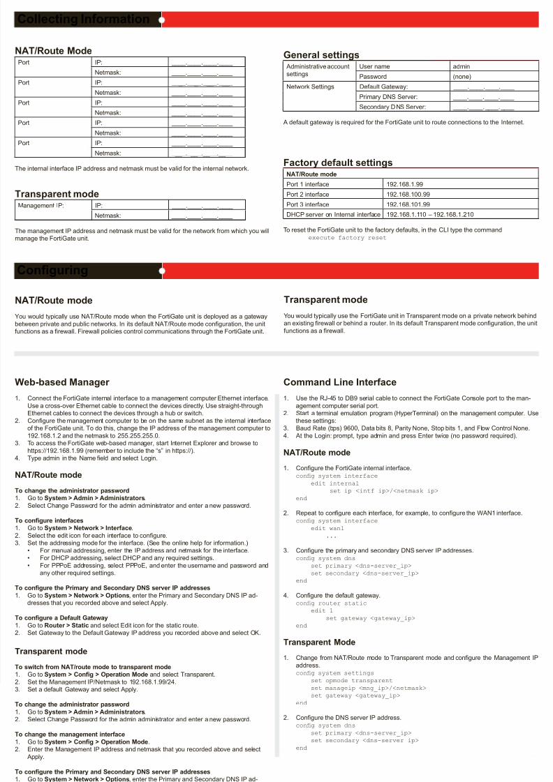
NAT/Route ModePort IP: ____.____.____.____
Netmask: ____.____.____.____
Port IP: ____.____.____.____
Netmask: ____.____.____.____
Port IP: ____.____.____.____
Netmask: ____.____.____.____
Port IP: ____.____.____.____
Netmask: ____.____.____.____
Port IP: ____.____.____.____
Netmask: ____.____.____.____
The internal interface IP address and netmask must be valid for the internal network.
Transparent modeManagement IP: IP: ____.____.____.____
Netmask: ____.____.____.____
The management IP address and netmask must be valid for the network from which you willmanage the FortiGate unit.
Web-based Manager
1. Connect the FortiGate internal interface to a management computer Ethernet interface.
Use a cross-over Ethernet cable to connect the devices directly. Use straight-through
Ethernet cables to connect the devices through a hub or switch.2. Congure the management computer to be on the same subnet as the internal interface
of the FortiGate unit. To do this, change the IP address of the management computer to
192.168.1.2 and the netmask to 255.255.255.0.3. To access the FortiGate web-based manager, start Internet Explorer and browse to
https://192.168.1.99 (remember to include the “s” in https://).4. Type admin in the Name eld and select Login.
NAT/Route mode
To change the administrator password1. Go to System > Admin > Administrators.
2. Select Change Password for the admin administrator and enter a new password.
To congure interfaces1. Go to System > Network > Interface.
2. Select the edit icon for each interface to congure.3. Set the addressing mode for the interface. (See the online help for information.)
• For manual addressing, enter the IP address and netmask for the interface.• For DHCP addressing, select DHCP and any required settings.
• For PPPoE addressing, select PPPoE, and enter the username and password andany other required settings.
To congure the Primary and Secondary DNS server IP addresses
1. Go to System > Network > Options, enter the Primary and Secondary DNS IP ad-dresses that you recorded above and select Apply.
To congure a Default Gateway
1. Go to Router > Static and select Edit icon for the static route.2. Set Gateway to the Default Gateway IP address you recorded above and select OK.
Transparent mode
To switch from NAT/route mode to transparent mode1. Go to System > Cong > Operation Mode and select Transparent.
2. Set the Management IP/Netmask to 192.168.1.99/24.3. Set a default Gateway and select Apply.
To change the administrator password
1. Go to System > Admin > Administrators.2. Select Change Password for the admin administrator and enter a new password.
To change the management interface
1. Go to System > Cong > Operation Mode.2. Enter the Management IP address and netmask that you recorded above and select
Apply.
To congure the Primary and Secondary DNS server IP addresses1. Go to System > Network > Options, enter the Primary and Secondary DNS IP ad-
dresses that you recorded above and select Apply.
Command Line Interface
1. Use the RJ-45 to DB9 serial cable to connect the FortiGate Console port to the man-
agement computer serial port.
2. Start a terminal emulation program (HyperTerminal) on the management computer. Usethese settings:
3. Baud Rate (bps) 9600, Data bits 8, Parity None, Stop bits 1, and Flow Control None.
4. At the Login: prompt, type admin and press Enter twice (no password required).
NAT/Route mode
1. Congure the FortiGate internal interface.cong system interface
edit internalset ip <intf_ip>/<netmask_ip>
end
2. Repeat to congure each interface, for example, to congure the WAN1 interface.cong system interface
edit wan1...
3. Congure the primary and secondary DNS server IP addresses.cong system dns
set primary <dns-server_ip>
set secondary <dns-server_ip>end
4. Congure the default gateway.cong router static
edit 1
set gateway <gateway_ip>end
Transparent Mode
1. Change from NAT/Route mode to Transparent mode and congure the Management IP
address.cong system settings
set opmode transparent
set manageip <mng_ip>/<netmask>set gateway <gateway_ip>
end
2. Congure the DNS server IP address.cong system dns
set primary <dns-server_ip>set secondary <dns-server_ip>
end
Collecting Information
Conguring
NAT/Route mode
You would typically use NAT/Route mode when the FortiGate unit is deployed as a gateway
between private and public networks. In its default NAT/Route mode conguration, the unitfunctions as a rewall. Firewall policies control communications through the FortiGate unit.
Transparent mode
You would typically use the FortiGate unit in Transparent mode on a private network behindan existing rewall or behind a router. In its default Transparent mode conguration, the unit
functions as a rewall.
Refer to the Tools and Documentation CD for information on how to control trafc, and how to congure HA, antivirus protection, FortiGuard, Web content ltering, Spam ltering, intrusionprevention (IPS), and virtual private networking (VPN).
General settingsAdministrative account
settings
User name admin
Password (none)
Network Settings Default Gateway: ____.____.____.____
Primary DNS Server: ____.____.____.____
Secondary DNS Server: ____.____.____.____
A default gateway is required for the FortiGate unit to route connections to the Internet.
Factory default settingsNAT/Route mode
Port 1 interface 192.168.1.99
Port 2 interface 192.168.100.99
Port 3 interface 192.168.101.99
DHCP server on Internal interface 192.168.1.110 – 192.168.1.210
To reset the FortiGate unit to the factory defaults, in the CLI type the commandexecute factory reset