FormZ Tips created by Phil Jones, edited by Nancy Cheng...
6
window tools: 1 set reference plane use this to choose between standard reference planes. 2 perpendicular switch use this to lock movements perpendicular to the refer- ence plane. slightly darker grey means switch is on. 3 modify reference plane use these tools to move, ro- tate and extend the reference plane 4 toggle grid turns grid on and off. double click to change grid size. slightly darker grey means grid is on. 5 angle snaps use this to lock movements to 90° or other angles 6 object snaps like illustrator’s smart guides. allows you to lock to specifi c aspects of objects 7 zoom tools allow you to pan and zoom the view 8 view tools allow you to rotate and modify the viewing angle. set view is par- ticulary useful. 9 navigate menu allows you to move through the model 1 2 3 4 5 6 7 8 9 FormZ Tips created by Phil Jones, edited by Nancy Cheng, University of Oregon 11/16/05
Transcript of FormZ Tips created by Phil Jones, edited by Nancy Cheng...

window tools:
1 set reference planeuse this to choose between standard reference planes.
2 perpendicular switchuse this to lock movements perpendicular to the refer-ence plane. slightly darker grey means switch is on.
3 modify reference planeuse these tools to move, ro-tate and extend the reference plane
4 toggle gridturns grid on and o�. double click to change grid size. slightly darker grey means grid is on.
5 angle snapsuse this to lock movements to 90° or other angles
6 object snapslike illustrator’s smart guides. allows you to lock to speci� c aspects of objects
7 zoom toolsallow you to pan and zoom the view
8 view toolsallow you to rotate and modify the viewing angle. set view is par-ticulary useful.
9 navigate menuallows you to move throughthe model
1 2 3 4 5 6 7 8 9
FormZ Tipscreated by Phil Jones, edited by Nancy Cheng, University of Oregon 11/16/05

palettes:use the palettes menu to show and hide palettes
palettes all work pretty much the same way:
check mark indicates item is selected, click to toggle selection on and off
double click name of item to edit name and properties
click in palette under the last name to create a new item or (in object menu) group.
in lights palette, arrow and line indicate that light is casting shadows. click to toggle on and off.
in lights palette, circle indicates light is shining. click to toggle on and off.
lock icon indicates item is locked. click to toggle on and off
click diamonds to toggle visibility: black = visible, white = ghosted, missing = invisible
surface styles:
selected style (outlined in black) is ap-plied to objects that you click on with the color tool
double click style to edit its name and properties
prompts:
prompts palette displays information about the objects you are drawing or modifying. you can also type values here.
if your prompts palette is set up as shown, you can see the length and width of objects you are creating.

object type:setting for drawing tools (i.e., rectangle, vector line)
governs how new ob-jects are created
topological level:setting for pick tool (and any tool that acts on existing objects)
governs which level of an object form z will operate on
use the automatic set-ting to select different levels more intuitively. (to select an entire object in auto mode, hold option (PC: alt) and click on an edge of the object)
insertions:setting for drawing tools (i.e., rectangle, vector line)
like object type, except these add to or sub-tract from an existing object. requires you to prepick one (and only surface) to operate on.
self/copy:setting for transforma-tion tools
governs whether transformation tools modify a shape or cre-ate duplicates of it
FORM Z SWITCHES:
more info on these can be found in the form z help menu.

derivatives:use to generate new objects from exist-ing objects. double click tools to change how they work (and what the do with the original object)
use terrain model to gener-ate 3d landforms from a topo map
use 3d ex-trude to take a 2d surface (can be one surface of a 3d object) and extrude it.MODELING TOOLS:
more info on these can be found in the form z help menu.
lines, polygons, et al:use these to draw new objects. what type of object you make (2d surface, 3d extrusion, etc.) is determined by the setting of the “object type” and “insertions” switches. (see previous page).
transformations:use these to move, rotate, scale, and mirror objects. follow the cues in the prompts palette. whether a transformation copies or just modifies an object depends on the setting of the “self/copy” switch (see previous page).
pick tool:use to select objects or parts of objects. multiple objects can be se-lected. to deselect an object, click it again. to deselct all objects, click on the background.
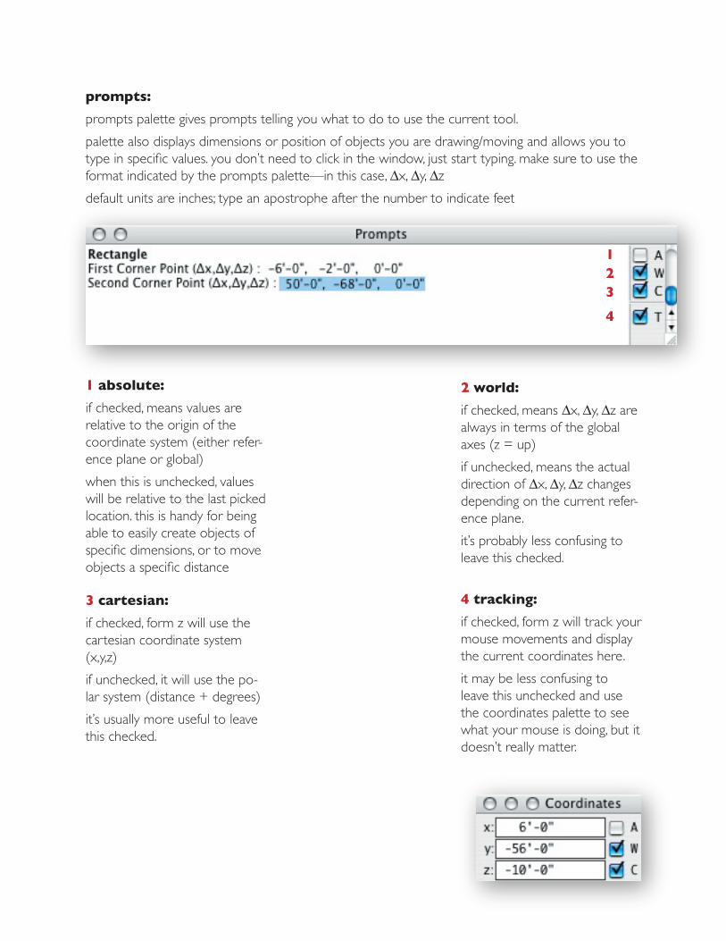
prompts:
prompts palette gives prompts telling you what to do to use the current tool.
palette also displays dimensions or position of objects you are drawing/moving and allows you to type in specific values. you don’t need to click in the window, just start typing. make sure to use the format indicated by the prompts palette—in this case, ∆x, ∆y, ∆z
default units are inches; type an apostrophe after the number to indicate feet
1 absolute:
if checked, means values are relative to the origin of the coordinate system (either refer-ence plane or global)
when this is unchecked, values will be relative to the last picked location. this is handy for being able to easily create objects of specific dimensions, or to move objects a specific distance
2 world:
if checked, means ∆x, ∆y, ∆z are always in terms of the global axes (z = up)
if unchecked, means the actual direction of ∆x, ∆y, ∆z changes depending on the current refer-ence plane.
it’s probably less confusing to leave this checked.
3 cartesian:
if checked, form z will use the cartesian coordinate system (x,y,z)
if unchecked, it will use the po-lar system (distance + degrees)
it’s usually more useful to leave this checked.
4 tracking:
if checked, form z will track your mouse movements and display the current coordinates here.
it may be less confusing to leave this unchecked and use the coordinates palette to see what your mouse is doing, but it doesn’t really matter.
3
12
4

eye point:(camera position)drag this (it looks like a little square) to move the physical position of your camera
center of interest:(what the camera is pointing at)drag this (it looks like a little plus sign) to aim your camera
view angle:(a pyramid defining the area of the model that is visble)drag here to zoom the camera in and out
edit cone of visionto enter edit cone of vision mode, select edit cone of vision from the view menu
use the different window frames to position the camera accurately (use top view to move and aim the camera in plan, front and right views to move and aim it up and down)
click in the views palette to save the current view
to exit, select edit cone of vision again from the view menu
to enter perspective mode, choose “perspective” from the view menu. to return to axonometric mode, choose “axonometric”.
cone of vision settings can also be adjusted numerically by selecting “view parameters” from the view menu. this is helpful if you accidentally spun your camera and you want it to go back to being level.


![[1] Background should be set to formZ classic (white). See ... · formZ export image process 1 [1] Background should be set to formZ classic (white). See appearance in Project Settings](https://static.fdocuments.us/doc/165x107/5accbf2e7f8b9a93268cd245/1-background-should-be-set-to-formz-classic-white-see-export-image-process.jpg)