Formwork for Concrete - University of Washingtoncourses.washington.edu/cm323/formwork.pdf ·...
43
Construction Methods & Materials II Temporary Structures Professor Kamran M. Nemati Winter Quarter 2016 Construction Methods and Materials II Concrete Formwork and Shoring Systems Construction Methods & Materials II 2 Temporary Structures Definition Any means or methods which provide temporary support, access, enhancement, or otherwise facilitate the construction of permanent structures. Necessity Temporary structures form the interface between design and construction. Most permanent structures simply could not be built without temporary structures. Impact on Schedule, Cost, and Quality Losses in time and money will occur if the temporary structures are not planned and coordinated with the same degree of thoroughness as the permanent structures.
Transcript of Formwork for Concrete - University of Washingtoncourses.washington.edu/cm323/formwork.pdf ·...

Construction Methods & Materials II
Temporary Structures
Professor Kamran M. Nemati
Winter Quarter 2016
Construction
Methods and Materials II
Concrete Formworkand Shoring Systems
Construction Methods & Materials II
2
Temporary Structures Definition
Any means or methods which provide temporary support, access, enhancement, or otherwise facilitate the construction of permanent structures.
Necessity
Temporary structures form the interface between design and construction. Most permanent structures simply could not be built without temporary structures.
Impact on Schedule, Cost, and Quality
Losses in time and money will occur if the temporary structures are not planned and coordinated with the same degree of thoroughness as the permanent structures.

Construction Methods & Materials II
Temporary Structures
Professor Kamran M. Nemati
Winter Quarter 2016
Construction Methods & Materials II
3
Temporary Structures The common temporary structures utilized in
various construction operations are:
concrete formwork construction
scaffolding
falsework/shoring
cofferdams
underpinning
diaphram/slurry walls
earth-retaining structures
construction dewatering.
This lecture will focus on concrete formwork construction.
Construction Methods & Materials II
4
The term “Temporary Structures” may not fully imply the temporary, since some forms, tie hardware, and accessories are used hundreds of times, which necessitates high durability and maintainability characteristics and design that maximizes productivity.
Unlike conventional structures, the formwork disassembly characteristics are severely restricted by concrete bond, rigidity, and shrinkage, which not only restricts access to the formwork structure but causes residual loads that have to be released to allow stripping from the concrete which initiates disassembly.
Formwork for Concrete

Construction Methods & Materials II
Temporary Structures
Professor Kamran M. Nemati
Winter Quarter 2016
Construction Methods & Materials II
5
Basic objectives in form building:
Quality - In terms of strength, rigidity, position, and dimensions of the forms
Safety - for both the workers and the concrete structure
Economy - the least cost consistent with quality and safety required
Cooperation and coordination between engineer-architect and the builder or contractor are necessary to achieve these goals.
Formwork for Concrete
Construction Methods & Materials II
6
Objectives of Formwork Building
Forms mold the concrete to desired size and shape and control its position and alignment.
Formwork is a temporary structure that supports its own weight + the freshly placed concrete +construction live loads (materials, equipment, and people).
Size, shape, and alignment of slabs, beams, and other concrete structural elements depend on accurate construction of the forms.
The formwork must remain in place until the concrete is strong enough to carry its own weight, or the finished structure may be damaged.

Construction Methods & Materials II
Temporary Structures
Professor Kamran M. Nemati
Winter Quarter 2016
Construction Methods & Materials II
7
In 1908 the use of wood versus steel formwork was debated at the ACI convention. The idea of modular panel forming was also introduced.
By 1910, steel forms were commercially available and used in the field.
Formwork for Concrete
Construction Methods & Materials II
8
Formwork is a classic temporary structure in the sense that:
it is erected quickly
highly loaded for a few hours during the concrete placement
and within a few days disassembled for future use.
Also classic in their temporary nature are the connections, braces, tie anchorages, and adjustment devices which forms need.
Formwork for Concrete
Construction Methods & Materials II
Temporary Structures
Professor Kamran M. Nemati
Winter Quarter 2016
Construction Methods & Materials II
9
Traditionally lumber has been the prominent form material.
Today plywood, metal, plastics, and other materials are commonly used for formwork.
In the past formwork was built in place, used once, and wrecked.
Because of high labor costs, today formworks are prefabricated, assembled in large units, and erected by mechanical means, i.e., using crane, and continuing reuse of the forms.
Formwork for Concrete
Construction Methods & Materials II
Formwork for Concrete
Vertical formwork systems (wall and column systems)
Horizontal shoring systems (flying systems and stationary systems)
Factors Affecting Formwork and Shoring Designs

Construction Methods & Materials II
Temporary Structures
Professor Kamran M. Nemati
Winter Quarter 2016
Construction Methods & Materials II
Objectives and Goals
Develop an understanding of the current formwork and shoring systems available today.
Review typical applications and rental costs for each system.
Learn the factors that govern formwork and shoring designs – decisions that contractors face.
Be able to use this knowledge in evaluating formwork systems to fit the project.
11
Construction Methods & Materials II
Factors Affecting Formwork System Selection Safety Accident Prevention!!
Structure Type and Design
Floor-to-floor heights and changes
Column and wall layout
P/T slabs or conventionally reinforced slabs
Construction joint locations
Drop caps, slab breaks
Existing constraints (Adjacent Buildings)
Number of uses of form system
Crane size and location
Schedule (Very Important)
Manpower - Skill Level
Productivity and cycling of equipment12
Construction Methods & Materials II
Temporary Structures
Professor Kamran M. Nemati
Winter Quarter 2016
Construction Methods & Materials II
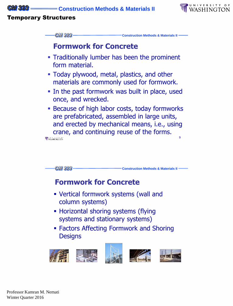
Factors Affecting Formwork System Selection Risk
Formwork Supplier
History with similar projects
Engineering expertise
Support services
Knowledge of support personnel
Location
Buy versus Rent
Duration of project
Future usage
Return on investment
Maintenance expense on owned equipment
Storage expense13
Construction Methods & Materials II
14
Formwork for Concrete Formwork costs constitutes up to 60 percent of the
total cost of concrete work in a project.
The architect and engineer can make savings possible by considering problems of formwork economy at the same time they design the concrete structure.
Formwork
material
cost
Concrete,
rebar,
footings,
placement
Formwork
Labor
Cost
Construction Methods & Materials II
Temporary Structures
Professor Kamran M. Nemati
Winter Quarter 2016
Construction Methods & Materials II
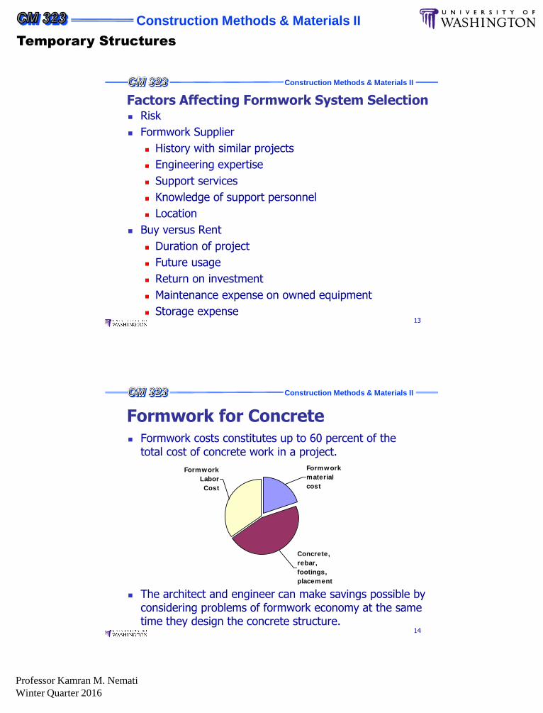
Vertical Formwork SystemsWood Forming System
Construction Methods & Materials II
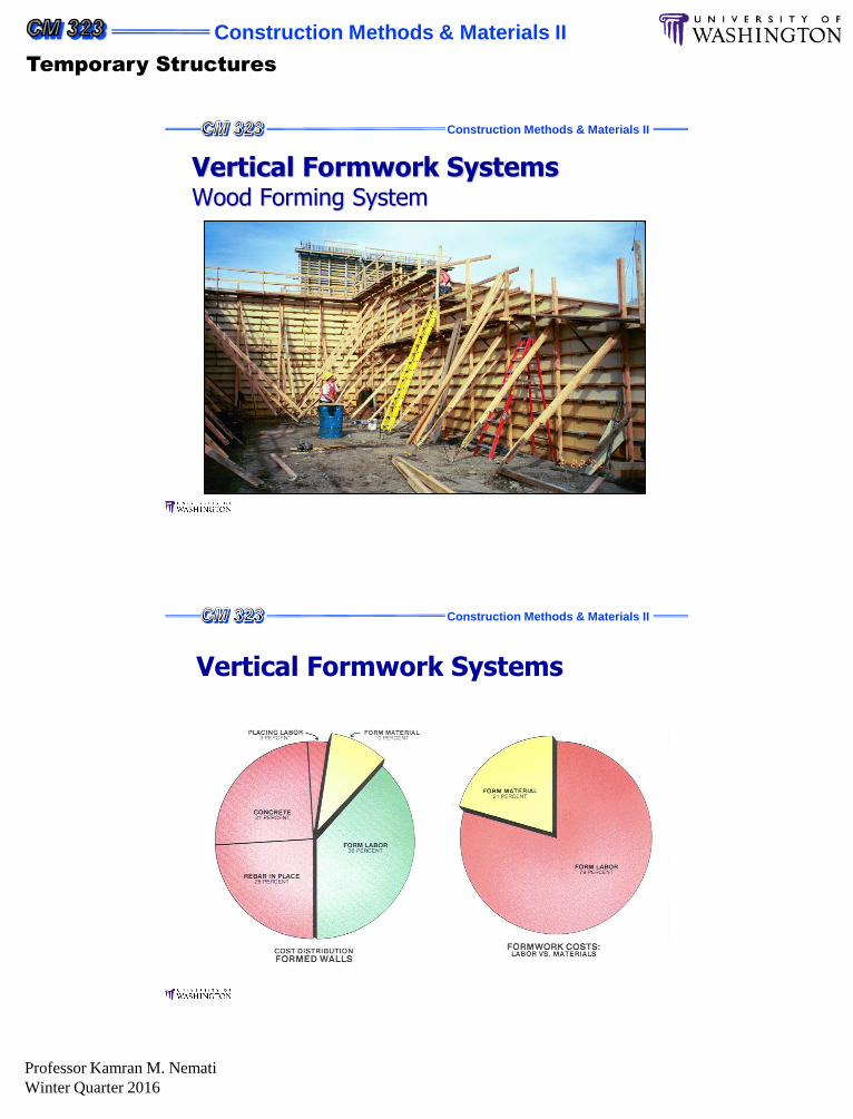
Vertical Formwork Systems

Construction Methods & Materials II
Temporary Structures
Professor Kamran M. Nemati
Winter Quarter 2016
Construction Methods & Materials II
Application: Walls and Columns
50% more productive than snap tie wall systems
Aluminum Frame with a 5/8” plywood face
Pour Pressures =1,200 psf
Ties on 2’ x 2’ spacings
Cost $0.85 to $1.00/sf per month
Vertical Formwork SystemsHand-set Forming System
Construction Methods & Materials II
Panel widths vary from 1” to 30”
Panel heights = 3’, 4’, 5’, 6’ and 8’
Vertical Formwork SystemsHand-set Forming System

Construction Methods & Materials II
Temporary Structures
Professor Kamran M. Nemati
Winter Quarter 2016
Construction Methods & Materials II
Quick Pre-assembly
Moveable by Hand Hinges and Carts Available Braced with 2” x 4”s
Vertical Formwork SystemsHand-set Forming System
Construction Methods & Materials II
Vertical Formwork Systems
Crane Set Forming System
Power Plants
BridgesTunnels
Commercial Building
Construction Methods & Materials II
Temporary Structures
Professor Kamran M. Nemati
Winter Quarter 2016
Construction Methods & Materials II
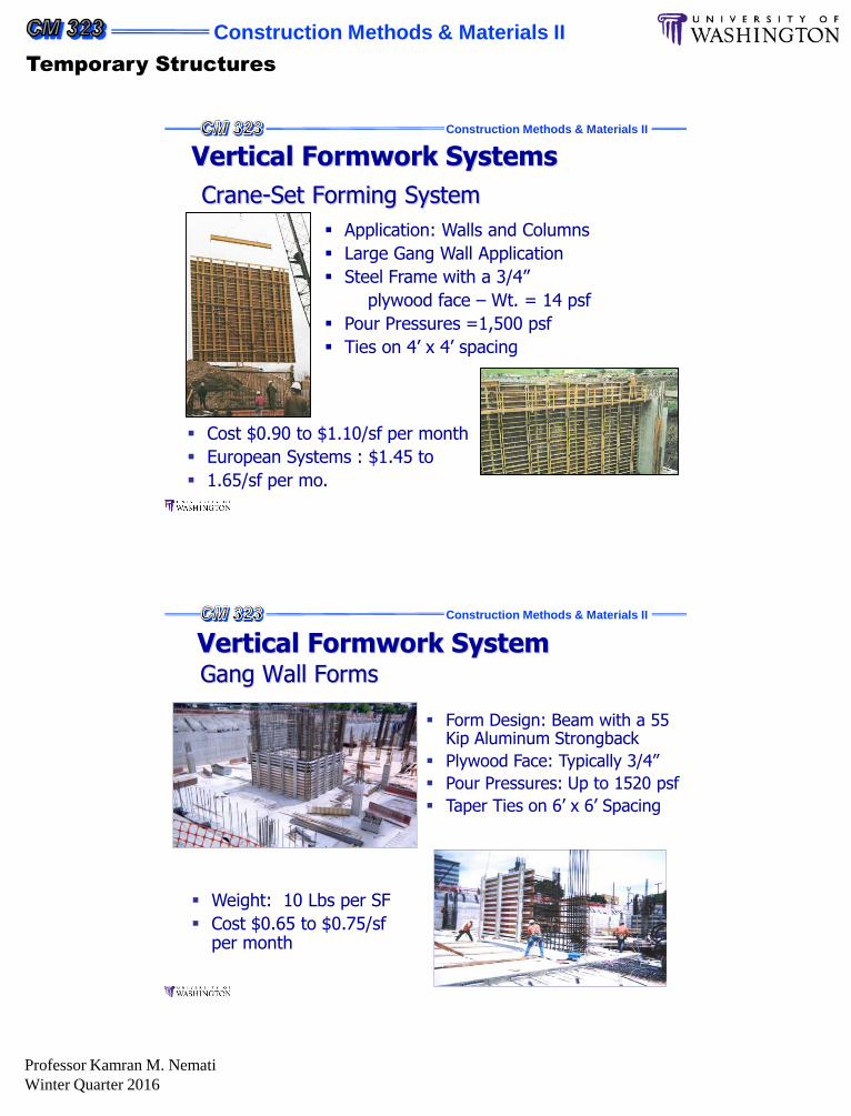
Vertical Formwork Systems
Crane-Set Forming System
Application: Walls and Columns
Large Gang Wall Application
Steel Frame with a 3/4”
plywood face – Wt. = 14 psf
Pour Pressures =1,500 psf
Ties on 4’ x 4’ spacing
Cost $0.90 to $1.10/sf per month
European Systems : $1.45 to
1.65/sf per mo.
Construction Methods & Materials II
Gang Wall Forms
Vertical Formwork System
Form Design: Beam with a 55 Kip Aluminum Strongback
Plywood Face: Typically 3/4”
Pour Pressures: Up to 1520 psf
Taper Ties on 6’ x 6’ Spacing
Weight: 10 Lbs per SF
Cost $0.65 to $0.75/sf per month

Construction Methods & Materials II
Temporary Structures
Professor Kamran M. Nemati
Winter Quarter 2016
Construction Methods & Materials II
Radius wall application
Gang Wall Forms
Vertical Formwork System
Construction Methods & Materials II
Roll Back Jump Forms
Vertical Formwork System
Problem: Multi-lift Wall Construction Elevator Cores Safe Access for Rebar,
Formwork and Concrete Placing Operations
Solution:Roll back Jump Form
Construction Methods & Materials II
Temporary Structures
Professor Kamran M. Nemati
Winter Quarter 2016
Construction Methods & Materials II
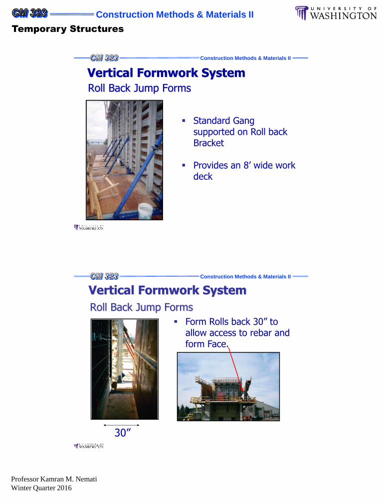
Roll Back Jump Forms
Vertical Formwork System
Standard Gang supported on Roll back Bracket
Provides an 8’ wide work deck
Construction Methods & Materials II
Roll Back Jump Forms
Vertical Formwork System
Form Rolls back 30” to allow access to rebar and form Face.
30”
Construction Methods & Materials II
Temporary Structures
Professor Kamran M. Nemati
Winter Quarter 2016
Construction Methods & Materials II
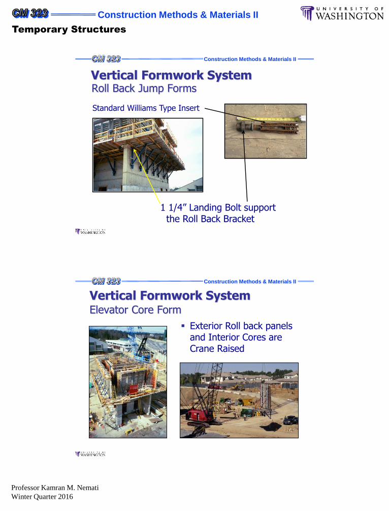
Roll Back Jump FormsVertical Formwork System
1 1/4” Landing Bolt supportthe Roll Back Bracket
Standard Williams Type Insert
Construction Methods & Materials II
Elevator Core Form
Exterior Roll back panels and Interior Cores are Crane Raised
Vertical Formwork System

Construction Methods & Materials II
Temporary Structures
Professor Kamran M. Nemati
Winter Quarter 2016
Construction Methods & Materials II
Horizontal Shoring Systems
Construction Methods & Materials II
Hand-Set Shoring Systems: Applications
Horizontal Shoring Systems
Horizontal Formwork for Cast in Place Concrete
Re-shoring

Construction Methods & Materials II
Temporary Structures
Professor Kamran M. Nemati
Winter Quarter 2016
Construction Methods & Materials II
Hand-Set Shoring Systems:
Applications
Horizontal Shoring Systems
Parking Garages
Truss Table Shoring
Construction Methods & Materials II
Frame Shoring System Hand-Set Shoring is rated
by the capacity per leg
15 kips per leg
Light weight – 6 x 6 frame weighs 44 lbs
Frame Heights of 8’ tall available
Horizontal Shoring Systems
Cost: Varies based on
Slab thickness (controls beam spacing)
Shore Heights (Frame stacks)
H = 10’: $ 0.35 to $0.45/sf
H = 10 to 15’: Say $0.55/sf

Construction Methods & Materials II
Temporary Structures
Professor Kamran M. Nemati
Winter Quarter 2016
Construction Methods & Materials II
Parking Garage
Horizontal Shoring Systems
Uses Manufacturer Beam Tables for Deck Support
Uses frames to support the beams
Construction Methods & Materials II
Step #1: Beam supports and beam sides are pre-assembled
Step #2: Deck Panels are Pre-Assembled
Parking GarageHorizontal Shoring Systems

Construction Methods & Materials II
Temporary Structures
Professor Kamran M. Nemati
Winter Quarter 2016
Construction Methods & Materials II
Step #3: Set Shoring Frames in place then add pre-assembled Beam Forms
Step #4: Set Pre-Assembled Beam panels in place
Parking GarageHorizontal Shoring Systems
Construction Methods & Materials II
Inserts are added to Deck Panels to allow the stripping of the beam sides and shoring
Parking GarageHorizontal Shoring Systems

Construction Methods & Materials II
Temporary Structures
Professor Kamran M. Nemati
Winter Quarter 2016
Construction Methods & Materials II
Step #5: Cross braces are removed and the frame legs are folding up to facilitate strip and moving
Step #6: A forklift lowers the forms and moves to the next concrete placement
Allows access to move system through set-up equipment
16’
Parking GarageHorizontal Shoring Systems
Construction Methods & Materials II
Casters allow forms to easily move through project
Parking GarageHorizontal Shoring Systems

Construction Methods & Materials II
Temporary Structures
Professor Kamran M. Nemati
Winter Quarter 2016
Construction Methods & Materials II
Parking GarageHorizontal Shoring Systems
Construction Methods & Materials II
Cost: Varies based on
Building Geometry (affects post spacing)
Shore Heights
Generally: $ 1.10 to $1.25/sf per month
2’ x 6’ Aluminum Deck panels, shore points are on a 6’ x 8’ grid
Application:
Faster cycle times on flat slab structures.
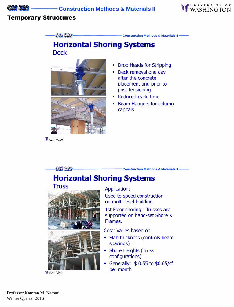
DeckHorizontal Shoring Systems
Construction Methods & Materials II
Temporary Structures
Professor Kamran M. Nemati
Winter Quarter 2016
Construction Methods & Materials II
Drop Heads for Stripping
Deck removal one day after the concrete placement and prior to post-tensioning
Reduced cycle time
Beam Hangers for column capitals
DeckHorizontal Shoring Systems
Construction Methods & Materials II
Cost: Varies based on
Slab thickness (controls beam spacings)
Shore Heights (Truss configurations)
Generally: $ 0.55 to $0.65/sf per month
1st Floor shoring: Trusses are supported on hand-set Shore X Frames.
Application:
Used to speed construction on multi-level building.
TrussHorizontal Shoring Systems

Construction Methods & Materials II
Temporary Structures
Professor Kamran M. Nemati
Winter Quarter 2016
Construction Methods & Materials II
5’ and 6’ deep truss
7’ and 10’ cross braces
Extension legs Jacks
• 12” – 18”
• 18” – 24”
• 24” – 30”
Lowering devices
Stripping and flying
Fillers
TrussHorizontal Shoring Systems
Construction Methods & Materials II
TrussHorizontal Shoring Systems
Construction Methods & Materials II
Temporary Structures
Professor Kamran M. Nemati
Winter Quarter 2016
Construction Methods & Materials II
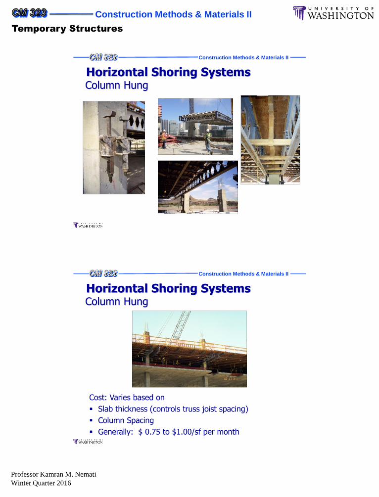
Column HungHorizontal Shoring Systems
Construction Methods & Materials II
Cost: Varies based on
Slab thickness (controls truss joist spacing)
Column Spacing
Generally: $ 0.75 to $1.00/sf per month
Column HungHorizontal Shoring Systems

Construction Methods & Materials II
Temporary Structures
Professor Kamran M. Nemati
Winter Quarter 2016
Construction Methods & Materials II
Column HungHorizontal Shoring Systems
Construction Methods & Materials II
Column HungHorizontal Shoring Systems
Construction Methods & Materials II
Temporary Structures
Professor Kamran M. Nemati
Winter Quarter 2016
Construction Methods & Materials II
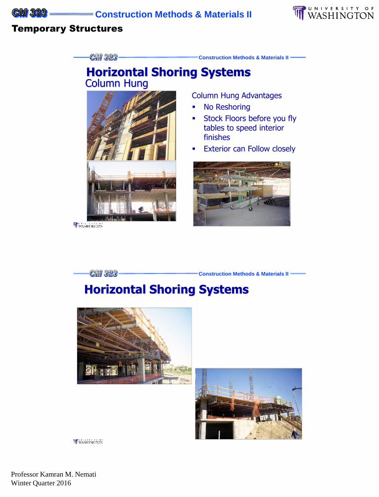
Column Hung Advantages
No Reshoring
Stock Floors before you fly tables to speed interior finishes
Exterior can Follow closely
Column HungHorizontal Shoring Systems
Construction Methods & Materials II
Horizontal Shoring Systems
Construction Methods & Materials II
Temporary Structures
Professor Kamran M. Nemati
Winter Quarter 2016
Construction Methods & Materials II
51
Failure of Formwork
Formwork failures are the cause of many accidents and failures that occur during concrete construction which usually happen when fresh concrete is being placed.
Generally some unexpected event causes one member to fail, then others become overloaded or misaligned and the entire formwork structure collapses.
Construction Methods & Materials II
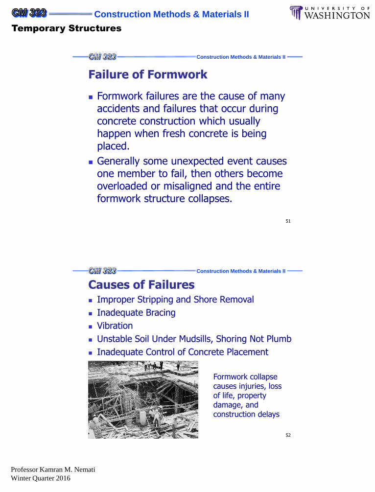
52
Causes of Failures Improper Stripping and Shore Removal
Inadequate Bracing
Vibration
Unstable Soil Under Mudsills, Shoring Not Plumb
Inadequate Control of Concrete Placement
Formwork collapse causes injuries, loss of life, property damage, and construction delays
Construction Methods & Materials II
Temporary Structures
Professor Kamran M. Nemati
Winter Quarter 2016
Construction Methods & Materials II
53
Improper Stripping and Shore Removal
Premature stripping of forms, premature removal of shores, and careless practices in shoring can produce catastrophic results.
Case study: Too early shore removal at Bailey’s Crossroads in Virginia (1973):
26-stories + apartment building
Forms were supported by floors 7-days old or older
Failure occurred on the 24th floor, where it was shored to the 5-day-old 23rd floor.
The overloaded 23rd floor failed in shear around one or more columns, triggering a collapse that carried through the entire height of the building
Causes of Failures
Construction Methods & Materials II
54
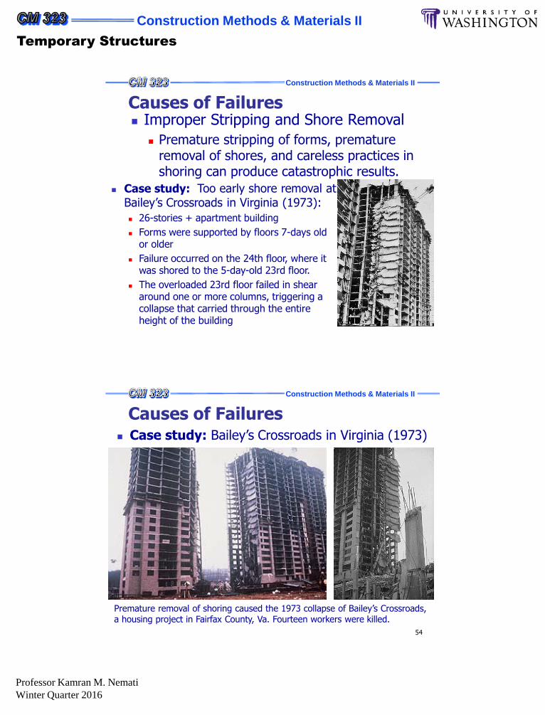
Case study: Bailey’s Crossroads in Virginia (1973)
Premature removal of shoring caused the 1973 collapse of Bailey’s Crossroads, a housing project in Fairfax County, Va. Fourteen workers were killed.
Causes of Failures

Construction Methods & Materials II
Temporary Structures
Professor Kamran M. Nemati
Winter Quarter 2016
Construction Methods & Materials II
55
Inadequate Bracing Failure in formwork can be caused by lateral force
components or other factors that induce displacement of supporting members.
Inadequate cross bracing and horizontal bracing of shores is one of the factors most frequently involved in formwork accidents.
Case study: New York Coliseum (1955)
Formwork collapse, where rapid delivery of concrete introduced lateral forces at the top of high shoring.
Causes of Failures
Construction Methods & Materials II
56
Case study: New York Coliseum
Increased diagonal bracing was added to all remaining shoring, following partial collapse of formwork.
Causes of Failures
Construction Methods & Materials II
Temporary Structures
Professor Kamran M. Nemati
Winter Quarter 2016
Construction Methods & Materials II
57
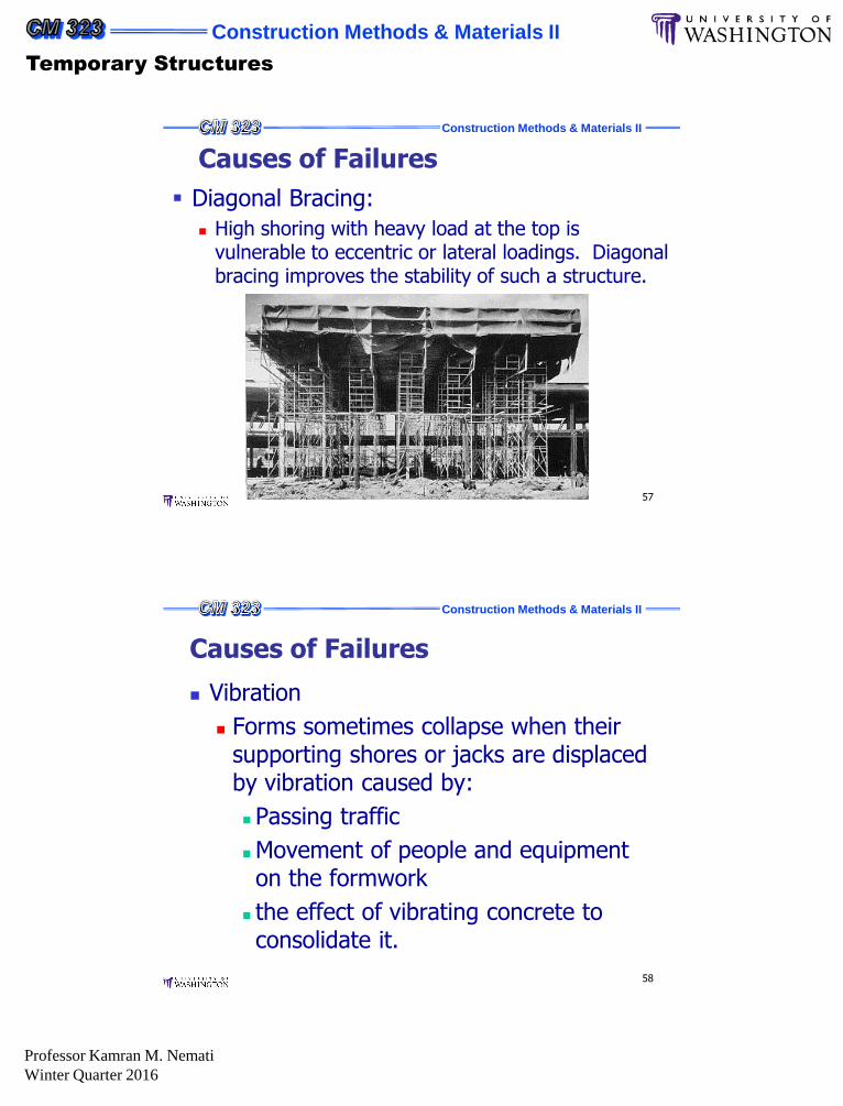
Diagonal Bracing:
High shoring with heavy load at the top is vulnerable to eccentric or lateral loadings. Diagonal bracing improves the stability of such a structure.
Causes of Failures
Construction Methods & Materials II
58
Vibration
Forms sometimes collapse when their supporting shores or jacks are displaced by vibration caused by:
Passing traffic
Movement of people and equipment on the formwork
the effect of vibrating concrete to consolidate it.
Causes of Failures

Construction Methods & Materials II
Temporary Structures
Professor Kamran M. Nemati
Winter Quarter 2016
Construction Methods & Materials II
59
Unstable Soil under Mudsills, Shoring not Plump
Forms should be safe and adequately braced and carry all loads to solid ground through vertical members.
Shores must be set plumb and the ground must be able to carry the load without settling.
Shores and mudsills must not rest on frozen ground, since moisture and heat from concreting operations, or changing air temperatures, may thaw the soil and allow settlement that overloads or shifts the formwork.
Site drainage must be adequate to prevent a washout of soil supporting the mudsill.
Causes of Failures
Construction Methods & Materials II
60
The temperature and rate of vertical placement of concrete are factors influencing the development of lateral pressures that act on the forms.
If temperature drops during construction operations, rate of concrete placement has to slow down to prevent a buildup of lateral pressure overloading the forms.
H
Fresh
Concrete
Inadequate Control of Concrete Placement
Causes of Failures

Construction Methods & Materials II
Temporary Structures
Professor Kamran M. Nemati
Winter Quarter 2016
Construction Methods & Materials II
61
Planning for Safety OSHA (Occupational Safety and Health
Administration) regulations, ACI recommendations, and local code requirements for formwork should be followed.
Supervision and Inspection
Platform and Access for Workers
Control of Concreting Practices
Improving Soil Bearing and Bracing
Shoring and Reshoring
Relationship of Architect, Engineer and Contractor
Maintaining and Coordinating Tolerances
Preparing a Formwork Specification
Construction Methods & Materials II
62
Formwork Materials & Accessories
Practically all formwork jobs require some lumber.
Local supplier will advise what material and sizes are in stock or promptly obtainable, and the designer or builder can proceed accordingly.
Southern yellow pine and Douglas fir, sometimes called Oregon pine are widely used in structural concrete form.
They are easily worked and are the strongest in the softwood group. Both hold nails well and are durable.
They are used in sheathing, studs, and wales.
Construction Methods & Materials II
Temporary Structures
Professor Kamran M. Nemati
Winter Quarter 2016
Construction Methods & Materials II
63
Form Materials and Accessories
Construction Methods & Materials II
64
Lumber which has been surfaced in a planing machine to attain smoothness of surface and uniformity of size is called “dressed” lumber.
The surfacing may be on one side (S1S), one edge (S1E), two sides (S2S), two edges (S2E), or combination of sides and edges (S1S1E, S1S2E, S2S1E) or on all four sides (S4S).
Dressed lumber is generally used for formwork, because it is easier to handle and work, but rough sawn boards and timbers may be used in bracing and shoring, or as a form surfacing material to secure a special texture effect in the finished concrete.
Form Materials and Accessories

Construction Methods & Materials II
Temporary Structures
Professor Kamran M. Nemati
Winter Quarter 2016
Construction Methods & Materials II
65
Minimum sizes of both rough and dressed lumber are specified by the American Softwood Lumber Standards, PS 20-70. It changes the dimensions to equate green and dry lumber.
Lumber is commonly referred to by its nominal size.
Minimum sizes for green lumber are selected so that as moisture is lost, it becomes the same size as dry lumber.
Specified actual size of a 24 for different moisture contents and finishes.
Form Materials and Accessories
Construction Methods & Materials II
66
Table 4-1B shows actual dimensions and cross section properties of American Standard lumber at 19 percent moisture content.
Actual, not nominal, sizes must always be used for design.
Form Materials and Accessories

Construction Methods & Materials II
Temporary Structures
Professor Kamran M. Nemati
Winter Quarter 2016
Construction Methods & Materials II
67
Design for formwork is based on the allowable or working stresses.
Allowable stress depends on so many factors including the species of wood, grade, cross section, moisture content, and load duration.
Table 4-2 shows base design values for several species of wood in common use for formwork.
Form Materials and Accessories
Construction Methods & Materials II
68
Form Materials and AccessoriesEngineered Wood Products
Plywood
Plywood is widely used for job built forms and prefabricated form panel systems.
Plywood is a flat panel made of a number of thin sheets of wood. A single sheet in the panel may be referred to as a ply, or layer.
A layer may consist of a single ply or it may be two or more plies laminated together with their grain direction parallel.
Construction Methods & Materials II
Temporary Structures
Professor Kamran M. Nemati
Winter Quarter 2016
Construction Methods & Materials II
69
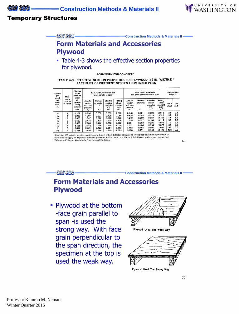
Table 4-3 shows the effective section properties for plywood.
Form Materials and Accessories Plywood
Construction Methods & Materials II
70
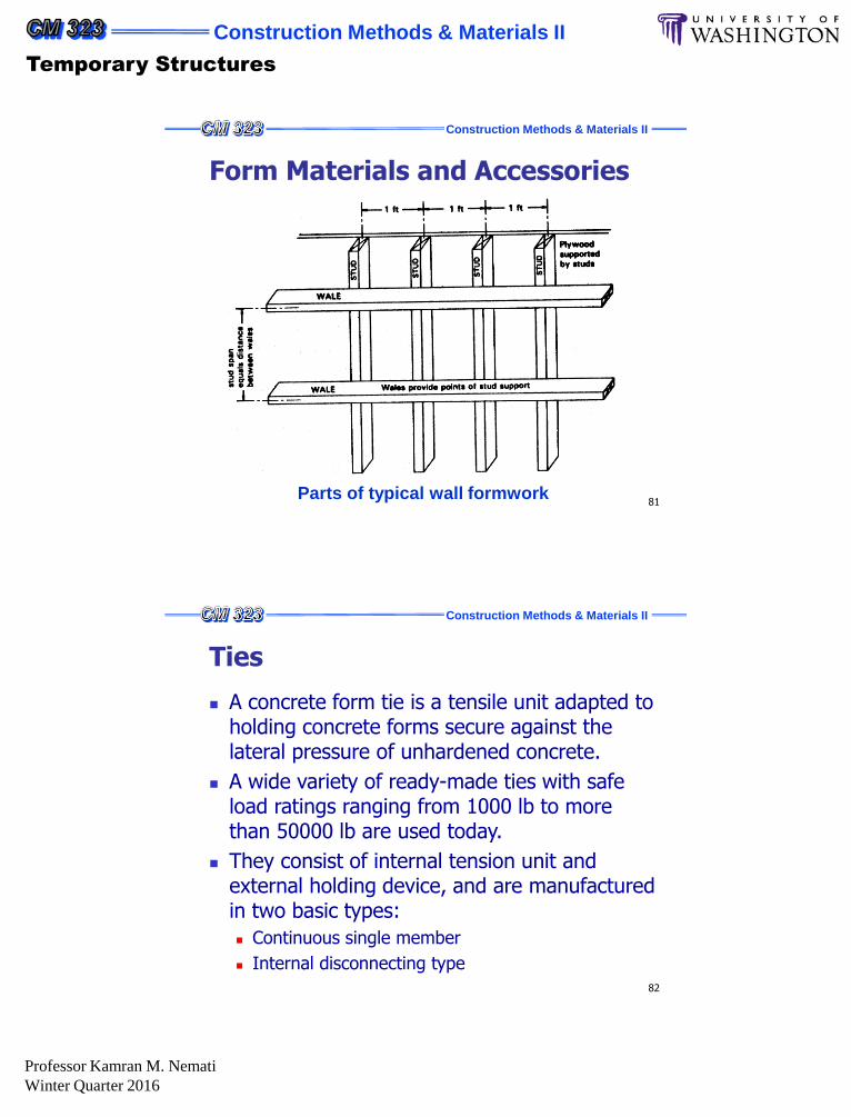
Form Materials and Accessories Plywood
Plywood at the bottom -face grain parallel to span -is used the strong way. With face grain perpendicular to the span direction, the specimen at the top is used the weak way.

Construction Methods & Materials II
Temporary Structures
Professor Kamran M. Nemati
Winter Quarter 2016
Construction Methods & Materials II
71
Loads and Pressures Formwork for concrete must support all vertical
and lateral loads that may be applied until such time as these loads can be carried by the concrete structure itself.
Loads on the forms include:
The weight of reinforcing steel and fresh concrete
the weight of the forms themselves
various live loads imposed during the construction process
Dumping of concrete, movement of construction equipment, and action of the wind may produce lateral forces which must be resisted by the formwork to prevent lateral failure.
Construction Methods & Materials II
72
Vertical Loads
Vertical loads on formwork include:
the weight of reinforced concrete
the weight of forms themselves (dead load)
the live loads imposed during the construction process (material storage, personnel and equipment).
The concrete weighs 150 pcf, it will place a load on the forms of 12.5 psf for each inch of slab thickness. i.e., a 6-inch slab would produce a dead load of 12.56 = 75 psf (neglecting the weight of the form)

Construction Methods & Materials II
Temporary Structures
Professor Kamran M. Nemati
Winter Quarter 2016
Construction Methods & Materials II
73
Vertical Loads
ACI Committee 347 recommends that both vertical supports and horizontal framing components of formwork should be designed for a minimum live load of 50 psf of horizontal projection to provide for weight of personnel, runways, screeds and other equipment.
When motorized carts are used, the minimum should be 75 psf.
Regardless of slab thickness, the minimum design value for combined dead and live loads should be 100 psf, or 125 psf if motorized carts are used.
Construction Methods & Materials II
74
Vertical Loads
Live load including power buggy and the concrete crew
(A minimum live load of 75 psf is recommended for design
where power buggies are used)

Construction Methods & Materials II
Temporary Structures
Professor Kamran M. Nemati
Winter Quarter 2016
Construction Methods & Materials II
75
Vertical Loads
Table 5-1 shows vertical loads on forms for various types of slabs of varying thickness (using minimum live load of 50 psf, and neglecting weight of the form, which may be added by designer)
Construction Methods & Materials II
76
Vertical Loads When slab form members are continuous over several
supporting shores, dumping concrete on one span of the form member may cause uplift of the form in other spans.
Forms must me designed to hold together under such conditions.
If form members are not secured to resist this uplift, they should be built as a simple pan.

Construction Methods & Materials II
Temporary Structures
Professor Kamran M. Nemati
Winter Quarter 2016
Construction Methods & Materials II
77
Formwork Design
When the material for formwork have been chosen, and the anticipated loading estimated, a form should be designed strong enough to carry the anticipated loads safely, and stiff enough to hold its shape under full load.
At the same time the builder or contractor wants to keep costs down by not overbuilding the form.
Construction Methods & Materials II
78
Form Materials and Accessories
Practically all formwork jobs require some lumber.
Local supplier will advise what material and sizes are in stock or promptly obtainable, and the designer or builder can proceed accordingly.
Southern yellow pine and Douglas fir, sometimes called Oregon pine are widely used in structural concrete form.
They are easily worked and are the strongest in the softwood group. Both hold nails well and are durable.
They are used in sheathing, studs, and wales.

Construction Methods & Materials II
Temporary Structures
Professor Kamran M. Nemati
Winter Quarter 2016
Construction Methods & Materials II
79
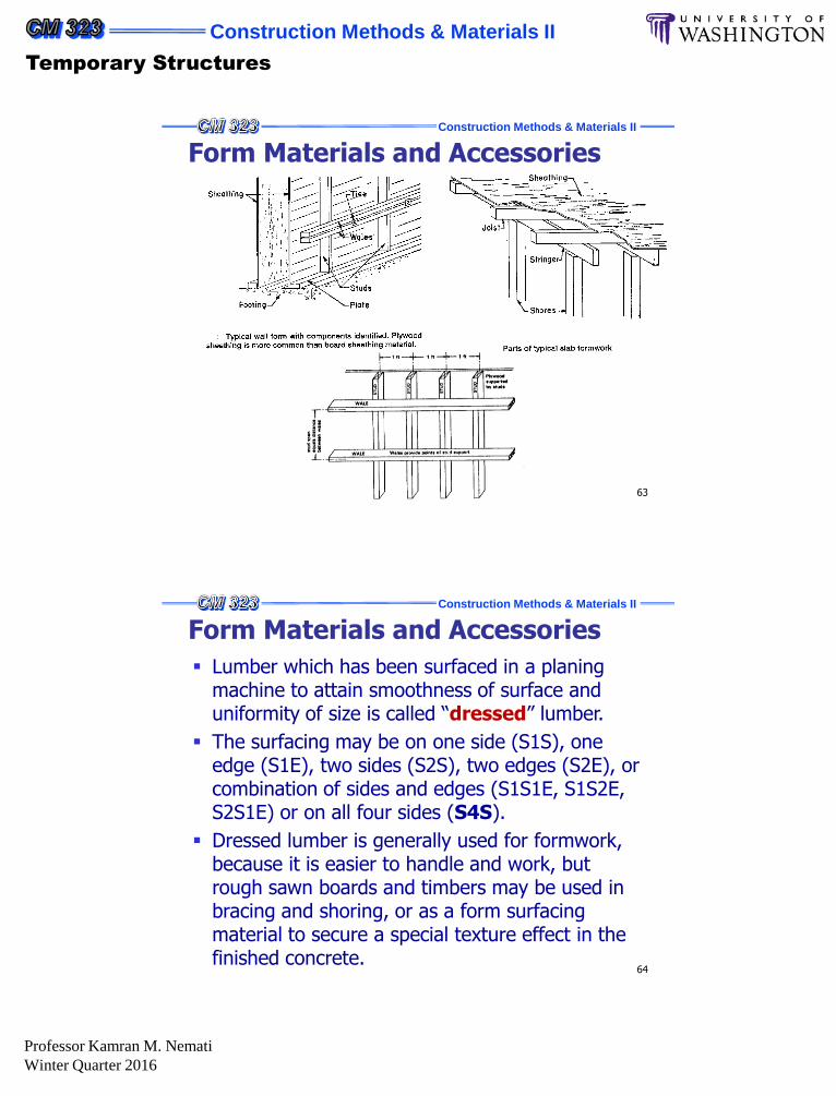
Form Materials and Accessories
Typical wall form with components identified. Plywood
sheathing is more common than board sheathing material.
A D
C
B
EF
Construction Methods & Materials II
80
Form Materials and Accessories
Parts of typical slab formwork
Construction Methods & Materials II
Temporary Structures
Professor Kamran M. Nemati
Winter Quarter 2016
Construction Methods & Materials II
81
Form Materials and Accessories
Parts of typical wall formwork
Construction Methods & Materials II
82
Ties
A concrete form tie is a tensile unit adapted to holding concrete forms secure against the lateral pressure of unhardened concrete.
A wide variety of ready-made ties with safe load ratings ranging from 1000 lb to more than 50000 lb are used today.
They consist of internal tension unit and external holding device, and are manufactured in two basic types:
Continuous single member
Internal disconnecting type
Construction Methods & Materials II
Temporary Structures
Professor Kamran M. Nemati
Winter Quarter 2016
Construction Methods & Materials II
83
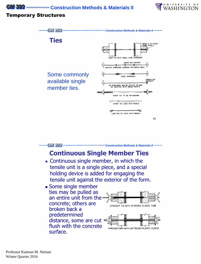
Ties
Some commonly
available single
member ties.
er
Construction Methods & Materials II
Continuous Single Member Ties Continuous single member, in which the
tensile unit is a single piece, and a special holding device is added for engaging the tensile unit against the exterior of the form.
Some single member ties may be pulled as an entire unit from the concrete; others are broken back a predetermined distance, some are cut flush with the concrete surface.

Construction Methods & Materials II
Temporary Structures
Professor Kamran M. Nemati
Winter Quarter 2016
Construction Methods & Materials II
Internal disconnecting Type Ties
Internal disconnecting type, in which the tensile unit has an inner part with threaded connections to removable external members which make up the rest of the tensile unit. They generally remain in the concrete.
Construction Methods & Materials II
Ties The two types of tying devices are identified
commercially by various descriptive names, such as form clamps, coil ties, rod clamps, snap ties, etc.
Except for taper ties, the continuous single member type is generally used for lighter loads, ranging up to about 5000 lb safe load.
The internal disconnecting type of tie is available for light or medium loads but finds its greatest application under heavier construction loads (up to about 70,000 lb).