Form measurngi systems from Jenoptik: Geometrci al … · Form measurngi systems from Jenoptik:...
1
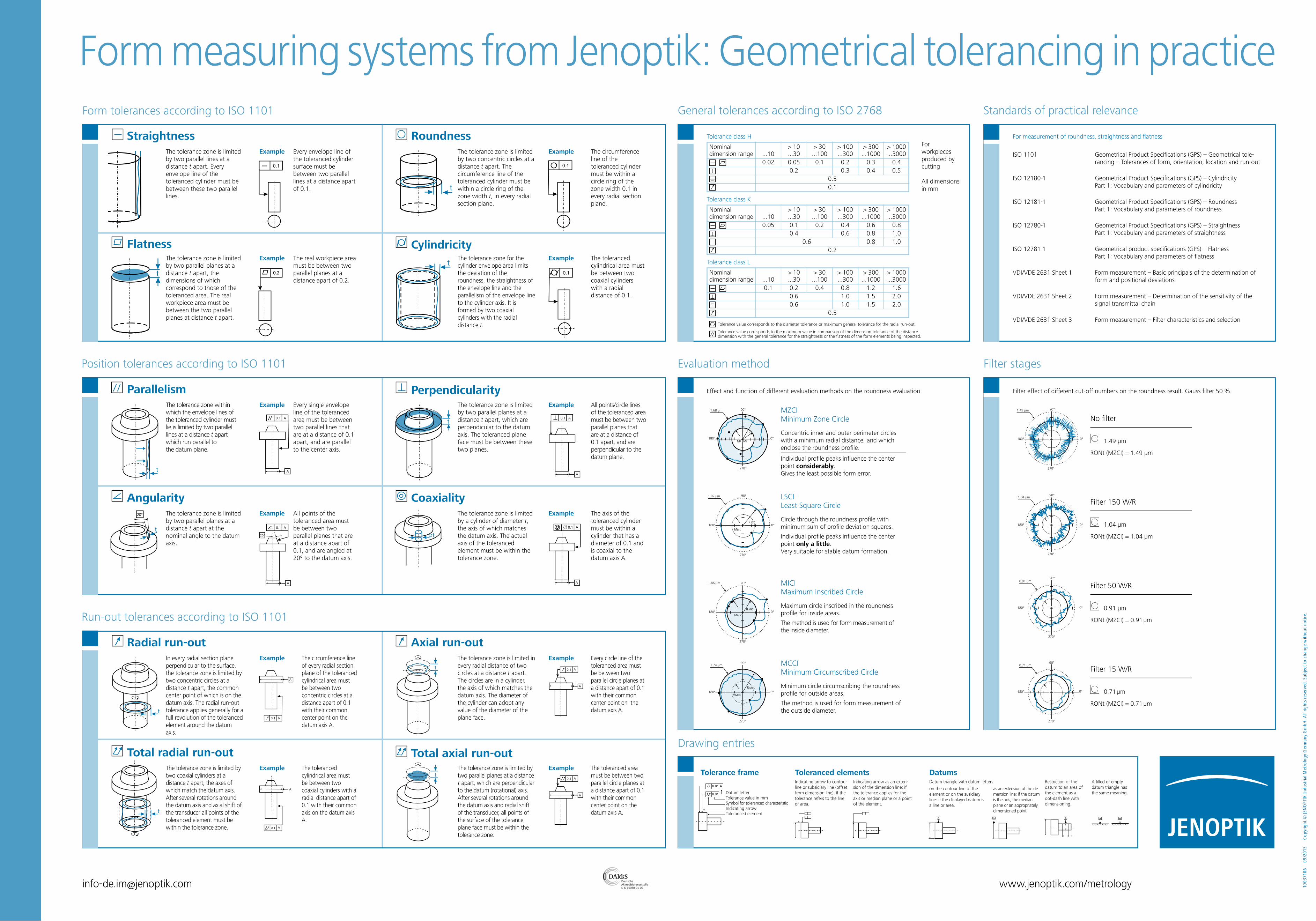
R r MR Mr 1.68 µm [email protected] www.jenoptik.com/metrology Form measuring systems from Jenoptik: Geometrical tolerancing in practice 10037106 09/2013 Copyright © JENOPTIK Industrial Metrology Germany GmbH. All rights reserved. Subject to change without notice. Drawing entries Position tolerances according to ISO 1101 Run-out tolerances according to ISO 1101 The tolerance zone is limited by two parallel lines at a distance t apart. Every envelope line of the toleranced cylinder must be between these two parallel lines. Straightness t The tolerance zone is limited by two parallel planes at a distance t apart, the dimensions of which correspond to those of the toleranced area. The real workpiece area must be between the two parallel planes at distance t apart. Example The real workpiece area must be between two parallel planes at a distance apart of 0.2. Flatness t The tolerance zone is limited by two concentric circles at a distance t apart. The circumference line of the toleranced cylinder must be within a circle ring of the zone width t, in every radial section plane. Example The circumference line of the toleranced cylinder must be within a circle ring of the zone width 0.1 in every radial section plane. Roundness t The tolerance zone for the cylinder envelope area limits the deviation of the roundness, the straightness of the envelope line and the parallelism of the envelope line to the cylinder axis. It is formed by two coaxial cylinders with the radial distance t. Example The toleranced cylindrical area must be between two coaxial cylinders with a radial distance of 0.1. Cylindricity t The tolerance zone within which the envelope lines of the toleranced cylinder must lie is limited by two parallel lines at a distance t apart which run parallel to the datum plane. Example Every single envelope line of the toleranced area must be between two parallel lines that are at a distance of 0.1 apart, and are parallel to the center axis. Parallelism t The tolerance zone is limited by two parallel planes at a distance t apart, which are perpendicular to the datum axis. The toleranced plane face must be between these two planes. Perpendicularity 20° t The tolerance zone is limited by two parallel planes at a distance t apart at the nominal angle to the datum axis. Example All points of the toleranced area must be between two parallel planes that are at a distance apart of 0.1, and are angled at 20º to the datum axis. Angularity t The tolerance zone is limited by a cylinder of diameter t, the axis of which matches the datum axis. The actual axis of the toleranced element must be within the tolerance zone. Example The axis of the toleranced cylinder must be within a cylinder that has a diameter of 0.1 and is coaxial to the datum axis A. Coaxiality t In every radial section plane perpendicular to the surface, the tolerance zone is limited by two concentric circles at a distance t apart, the common center point of which is on the datum axis. The radial run-out tolerance applies generally for a full revolution of the toleranced element around the datum axis. Example The circumference line of every radial section plane of the toleranced cylindrical area must be between two concentric circles at a distance apart of 0.1 with their common center point on the datum axis A. Radial run-out t The tolerance zone is limited in every radial distance of two circles at a distance t apart. The circles are in a cylinder, the axis of which matches the datum axis. The diameter of the cylinder can adopt any value of the diameter of the plane face. Example Every circle line of the toleranced area must be between two parallel circle planes at a distance apart of 0.1 with their common center point on the datum axis A. Axial run-out t The tolerance zone is limited by two coaxial cylinders at a distance t apart, the axes of which match the datum axis. After several rotations around the datum axis and axial shift of the transducer all points of the toleranced element must be within the tolerance zone. Example The toleranced cylindrical area must be between two coaxial cylinders with a radial distance apart of 0.1 with their common axis on the datum axis A. Total radial run-out t The tolerance zone is limited by two parallel planes at a distance t apart, which are perpendicular to the datum (rotational) axis. After several rotations around the datum axis and radial shift of the transducer, all points of the surface of the tolerance plane face must be within the tolerance zone. Example The toleranced area must be between two parallel circle planes at a distance apart of 0.1 with their common center point on the datum axis A. Total axial run-out Example All points/circle lines of the toleranced area must be between two parallel planes that are at a distance of 0.1 apart, and are perpendicular to the datum plane. Example Every envelope line of the toleranced cylinder surface must be between two parallel lines at a distance apart of 0.1. For workpieces produced by cutting All dimensions in mm Tolerance class H Nominal > 10 > 30 > 100 > 300 > 1000 dimension range ...10 ...30 ...100 ...300 ...1000 ...3000 0.02 0.05 0.1 0.2 0.3 0.4 0.2 0.3 0.4 0.5 0.5 0.1 Nominal > 10 > 30 > 100 > 300 > 1000 dimension range ...10 ...30 ...100 ...300 ...1000 ...3000 0.05 0.1 0.2 0.4 0.6 0.8 0.4 0.6 0.8 1.0 0.6 0.8 1.0 0.2 Nominal > 10 > 30 > 100 > 300 > 1000 dimension range ...10 ...30 ...100 ...300 ...1000 ...3000 0.1 0.2 0.4 0.8 1.2 1.6 0.6 1.0 1.5 2.0 0.6 1.0 1.5 2.0 0.5 Tolerance class K Tolerance class L Tolerance value corresponds to the diameter tolerance or maximum general tolerance for the radial run-out. Tolerance value corresponds to the maximum value in comparison of the dimension tolerance of the distance dimension with the general tolerance for the straightness or the flatness of the form elements being inspected. General tolerances according to ISO 2768 Standards of practical relevance ISO 1101 Geometrical Product Specifications (GPS) – Geometrical tole- rancing – Tolerances of form, orientation, location and run-out ISO 12180-1 Geometrical Product Specifications (GPS) – Cylindricity Part 1: Vocabulary and parameters of cylindricity ISO 12181-1 Geometrical Product Specifications (GPS) – Roundness Part 1: Vocabulary and parameters of roundness ISO 12780-1 Geometrical Product Specifications (GPS) – Straightness Part 1: Vocabulary and parameters of straightness ISO 12781-1 Geometrical product specifications (GPS) – Flatness Part 1: Vocabulary and parameters of flatness VDI/VDE 2631 Sheet 1 Form measurement – Basic principals of the determination of form and positional deviations VDI/VDE 2631 Sheet 2 Form measurement – Determination of the sensitivity of the signal transmittal chain VDI/VDE 2631 Sheet 3 Form measurement – Filter characteristics and selection Evaluation method Filter stages Filter 15 W/R 0.71 µm RONt (MZCI) = 0.71 µm Filter 50 W/R 0.91 µm RONt (MZCI) = 0.91 µm Filter 150 W/R 1.04 µm RONt (MZCI) = 1.04 µm No filter 1.49 µm RONt (MZCI) = 1.49 µm Filter effect of different cut-off numbers on the roundness result. Gauss filter 50 %. R LSC MLSC R MIC MMIC 90° MMCC R MCC MCCI Minimum Circumscribed Circle Minimum circle circumscribing the roundness profile for outside areas. The method is used for form measurement of the outside diameter. MICI Maximum Inscribed Circle Maximum circle inscribed in the roundness profile for inside areas. The method is used for form measurement of the inside diameter. LSCI Least Square Circle Circle through the roundness profile with minimum sum of profile deviation squares. Individual profile peaks influence the center point only a little. Very suitable for stable datum formation. MZCI Minimum Zone Circle Concentric inner and outer perimeter circles with a minimum radial distance, and which enclose the roundness profile. Individual profile peaks influence the center point considerably. Gives the least possible form error. Effect and function of different evaluation methods on the roundness evaluation. Tolerance frame Datum letter Tolerance value in mm Symbol for toleranced characteristic Indicating arrow Toleranced element Toleranced elements Indicating arrow to contour line or subsidiary line (offset from dimension line): if the tolerance refers to the line or area. Indicating arrow as an exten- sion of the dimension line: if the tolerance applies for the axis or median plane or a point of the element. Datums Restriction of the datum to an area of the element as a dot-dash line with dimensioning. Datum triangle with datum letters on the contour line of the element or on the susidiary line: if the displayed datum is a line or area. A filled or empty datum triangle has the same meaning. as an extension of the di- mension line: if the datum is the axis, the median plane or an appropriately dimensioned point. For measurement of roundness, straightness and flatness A A A A A Form tolerances according to ISO 1101 0.1 0.2 0.1 0.1 0.1 A A 0.1 A A 0.1 A A 20° 0.1 A A 0.1 A A 0.1 A A 0.1 A A 0.1 A A 0.01 0.01 A 0.71 µm 0.91 µm 1.04 µm 1.49 µm 1.74 µm 1.86 µm 1.92 µm 90° 90° 90° 90° 90° 90° 90° 180° 180° 180° 180° 180° 180° 180° 180° 0° 0° 0° 0° 0° 0° 0° 0° 270° 270° 270° 270° 270° 90° 270° 270° 270°
Transcript of Form measurngi systems from Jenoptik: Geometrci al … · Form measurngi systems from Jenoptik:...
R r
MR Mr 0°
90°
270°
360°1,68 µm1.68 µm
[email protected] www.jenoptik.com/metrology
Form measuring systems from Jenoptik: Geometrical tolerancing in practice
1003
710
6
09/
2013
C
opy
righ
t ©
JEN
OPT
IK In
dust
rial M
etro
log
y G
erm
any
Gm
bH
. All
righ
ts r
eser
ved.
Sub
ject
to
chan
ge w
ithou
t no
tice.
Drawing entries
Position tolerances according to ISO 1101
Run-out tolerances according to ISO 1101
t 0,1The tolerance zone is limited by two parallel lines at a distance t apart. Every envelope line of the toleranced cylinder must be between these two parallel lines.
Straightness
0,2
t
The tolerance zone is limited by two parallel planes at a distance t apart, the dimensions of which correspond to those of the toleranced area. The real workpiece area must be between the two parallel planes at distance t apart.
Example The real workpiece area must be between two parallel planes at a distance apart of 0.2.
Flatness
0,1
t
The tolerance zone is limited by two concentric circles at a distance t apart. The circumference line of the toleranced cylinder must be within a circle ring of the zone width t, in every radial section plane.
Example The circumference line of the toleranced cylinder must be within a circle ring of the zone width 0.1 in every radial section plane.
Roundness
0,1tThe tolerance zone for the cylinder envelope area limits the deviation of the roundness, the straightness of the envelope line and the parallelism of the envelope line to the cylinder axis. It is formed by two coaxial cylinders with the radial distance t.
Example The toleranced cylindrical area must be between two coaxial cylinders with a radial distance of 0.1.
Cylindricity
0,1
t
A
A
The tolerance zone within which the envelope lines of the toleranced cylinder must lie is limited by two parallel lines at a distance t apartwhich run parallel tothe datum plane.
Example Every single envelope line of the toleranced area must be between two parallel lines that are at a distance of 0.1 apart, and are parallel to the center axis.
Parallelism0,1 A
t
A
The tolerance zone is limited by two parallel planes at a distance t apart, which are perpendicular to the datum axis. The toleranced plane face must be between these two planes.
Perpendicularity
0,1 A
A
20°
20°t
The tolerance zone is limited by two parallel planes at a distance t apart at the nominal angle to the datum axis.
Example All points of the toleranced area must be between two parallel planes that are at a distance apart of 0.1, and are angled at 20º to the datum axis.
Angularity0,1 A
A
t
The tolerance zone is limited by a cylinder of diameter t, the axis of which matches the datum axis. The actual axis of the toleranced element must be within the tolerance zone.
Example The axis of the toleranced cylinder must be within a cylinder that has a diameter of 0.1 and is coaxial to the datum axis A.
Coaxiality
0,1 A
A
t
In every radial section plane perpendicular to the surface, the tolerance zone is limited by two concentric circles at a distance t apart, the common center point of which is on the datum axis. The radial run-out tolerance applies generally for a full revolution of the toleranced element around the datum axis.
Example The circumference line of every radial section plane of the toleranced cylindrical area must be between two concentric circles at a distance apart of 0.1 with their common center point on the datum axis A.
Radial run-out0,1 A
A
t
The tolerance zone is limited in every radial distance of two circles at a distance t apart. The circles are in a cylinder, the axis of which matches the datum axis. The diameter of the cylinder can adopt any value of the diameter of the plane face.
Example Every circle line of the toleranced area must be between two parallel circle planes at a distance apart of 0.1 with their common center point on the datum axis A.
Axial run-out
t
0,1 A
A
The tolerance zone is limited by two coaxial cylinders at a distance t apart, the axes of which match the datum axis. After several rotations around the datum axis and axial shift of the transducer all points of the toleranced element must be within the tolerance zone.
Example The toleranced cylindrical area must be between two coaxial cylinders with a radial distance apart of 0.1 with their common axis on the datum axis A.
Total radial run-out0,1 A
A
tThe tolerance zone is limited by two parallel planes at a distance t apart, which are perpendicular to the datum (rotational) axis. After several rotations around the datum axis and radial shift of the transducer, all points of the surface of the tolerance plane face must be within the tolerance zone.
Example The toleranced area must be between two parallel circle planes at a distance apart of 0.1 with their common center point on the datum axis A.
Total axial run-out
Example All points/circle lines of the toleranced area must be between two parallel planes that are at a distance of 0.1 apart, and are perpendicular to the datum plane.
Example Every envelope line of the toleranced cylinder surface must be between two parallel lines at a distance apart of 0.1.
For workpieces produced by cutting
All dimensions in mm
Tolerance class H
Nominal > 10 > 30 > 100 > 300 > 1000 dimension range ...10 ...30 ...100 ...300 ...1000 ...3000 0.02 0.05 0.1 0.2 0.3 0.4 0.2 0.3 0.4 0.5 0.5 0.1
Nominal > 10 > 30 > 100 > 300 > 1000 dimension range ...10 ...30 ...100 ...300 ...1000 ...3000 0.05 0.1 0.2 0.4 0.6 0.8 0.4 0.6 0.8 1.0 0.6 0.8 1.0 0.2
Nominal > 10 > 30 > 100 > 300 > 1000 dimension range ...10 ...30 ...100 ...300 ...1000 ...3000 0.1 0.2 0.4 0.8 1.2 1.6 0.6 1.0 1.5 2.0 0.6 1.0 1.5 2.0 0.5
Tolerance class K
Tolerance class L
Tolerance value corresponds to the diameter tolerance or maximum general tolerance for the radial run-out.
Tolerance value corresponds to the maximum value in comparison of the dimension tolerance of the distance dimension with the general tolerance for the straightness or the flatness of the form elements being inspected.
General tolerances according to ISO 2768 Standards of practical relevance
ISO 1101 Geometrical Product Specifications (GPS) – Geometrical tole- rancing – Tolerances of form, orientation, location and run-out
ISO 12180-1 Geometrical Product Specifications (GPS) – Cylindricity Part 1: Vocabulary and parameters of cylindricity
ISO 12181-1 Geometrical Product Specifications (GPS) – Roundness Part 1: Vocabulary and parameters of roundness
ISO 12780-1 Geometrical Product Specifications (GPS) – Straightness Part 1: Vocabulary and parameters of straightness
ISO 12781-1 Geometrical product specifications (GPS) – Flatness Part 1: Vocabulary and parameters of flatness
VDI/VDE 2631 Sheet 1 Form measurement – Basic principals of the determination of form and positional deviations
VDI/VDE 2631 Sheet 2 Form measurement – Determination of the sensitivity of the signal transmittal chain
VDI/VDE 2631 Sheet 3 Form measurement – Filter characteristics and selection
Evaluation method Filter stages
0°
90°
270°
360°0,71 µm
Filter 15 W/R
0.71 µm
RONt (MZCI) = 0.71 µm
0°
90°
270°
360°0,91 µm
Filter 50 W/R
0.91 µm
RONt (MZCI) = 0.91 µm
0°
90°
270°
360°1,04 µm
Filter 150 W/R
1.04 µm
RONt (MZCI) = 1.04 µm
0°
90°
270°
360°1,49 µm
No filter
1.49 µm
RONt (MZCI) = 1.49 µm
Filter effect of different cut-off numbers on the roundness result. Gauss filter 50 %.
R LSC
MLSC0°
90°
270°
360°1,92 µm
R MIC
MMIC0°
90°
270°
360°1,86 µm
MMCC
R MCC
0°
90°
270°
360°1,74 µm MCCI
Minimum Circumscribed Circle
Minimum circle circumscribing the roundness profile for outside areas.
The method is used for form measurement of the outside diameter.
MICI Maximum Inscribed Circle
Maximum circle inscribed in the roundness profile for inside areas.
The method is used for form measurement of the inside diameter.
LSCI Least Square Circle
Circle through the roundness profile with minimum sum of profile deviation squares.
Individual profile peaks influence the center point only a little. Very suitable for stable datum formation.
MZCI Minimum Zone Circle
Concentric inner and outer perimeter circles with a minimum radial distance, and which enclose the roundness profile.
Individual profile peaks influence the center point considerably. Gives the least possible form error.
Effect and function of different evaluation methods on the roundness evaluation.
Tolerance frame
Datum letterTolerance value in mmSymbol for toleranced characteristicIndicating arrow Toleranced element
PANTONE 3015 C
Toleranced elementsIndicating arrow to contour line or subsidiary line (offset from dimension line): if the tolerance refers to the line or area.
Indicating arrow as an exten-sion of the dimension line: if the tolerance applies for the axis or median plane or a point of the element.
DatumsRestriction of the datum to an area of the element as a dot-dash line with dimensioning.
Datum triangle with datum letters
on the contour line of the element or on the susidiary line: if the displayed datum is a line or area.
A filled or empty datum triangle has the same meaning.
as an extension of the di- mension line: if the datum is the axis, the median plane or an appropriately dimensioned point.
For measurement of roundness, straightness and flatness
A A AA A AA AA A
Form tolerances according to ISO 1101
t 0.1
0.2
t
0.1
t
0.1t
0.1
t
A
A
0.1 A
t
A
0.1 A
A
20°
20°t
0.1 A
A
t
0.1 A
A
t
t
0.1 A
A
0.1 A
A
t
0.1 A
A
t
0.01
0.01 A
0.71 µm
0.91 µm
1.04 µm
1.49 µm
1.74 µm
1.86 µm
1.92 µm
90°
90°
90°
90°
90°
90°
90°
180°
180°
180°
180° 180°
180°
180°
180° 0°
0°
0°
0°0°
0°
0°
0°
270°
270°
270°
270° 270°
90°
270°
270°
270°


![VOTAN® A engl.ppt [Kompatibilitätsmodus] · 2019. 7. 23. · JENOPTIK VOTAN® A Compact PP JENOPTIK-VOTAN® A Compact PP – system for producing of lines of pre-weakening in single-layer](https://static.fdocuments.us/doc/165x107/60af6180ed9ff32f533028e0/votan-a-englppt-kompatibilittsmodus-2019-7-23-jenoptik-votan-a-compact.jpg)