Torsional-lateral buckling – bifurcation analysis with a simple beam using Abaqus 6.10
Form and structural optimization:from beam modeling to 3D printing
of reinforced concrete members
PhD Candidate: Valentina Mercuri
Pavia, 12 March 2018
Degree of Doctor in Philosophy in Civil Engineering and
Architecture at Università degli Studi di Pavia
Supervisor: Prof. Ferdinando Auricchio
Co-supervisor: Prof. Domenico Asprone

Background
ARCHITECTURE & ENGINEERING FIELDS
Growing demand for designing complex and ambitious buildings
1
OBJECTIVES RESEARCH

Problem and motivations
2
RESEARCH
OPEN CHALLENGE:
Design, optimization and manufacturing of
structural elements with curved/
non-prismatic shapes
• DESIGN: non-prismatic elements behave
differently from prismatic ones
correct modelling strategy
• MANUFACTURING: to enable freedom in shape
reducing costs and time (material, labour
equipment, ..)
PROBLEMS
Usage motivations:
⋆ aesthetic
⋆ functional ⇒ economical
⋆ structural
COMMERCIAL SOFTWARE/
NUMERICAL TOOLS capabilities
INNOVATIVE TECHNOLOGIES VS TRADITIONAL
CONSTRUCTION METHODS (FORMWORK SYSTEMS..)

Goals of doctoral research
3
Implementation of an accurate non-prismatic beam model (NP-Model)
and its comparison with conventional building software in real
modeling problems
To propose an innovative 3D printing method for the production of
Reinforced Concrete (RC) non-prismatic elements and possible
compatible topology optimization tools
MODELING OF NON-PRISMATIC ELEMENTS
MANUFACTURING AND OPTIMIZATION METHODS

Modeling of non-prismatic elements
4
The governing differential equations of non-prismatic beams are characterized
by variable coefficients difficulties in the exact integration of the solution
Conventional Euler-Bernoulli and
Timoshenko beam theories are
NO longer valid!
NON-PRISMATIC BEAM BEHAVIOR:
Strong coupling between internal forces
Modification of boundary equilibrium
Non-trivial stress distribution
Complex constitutive relations
BASIC (POOR) MODELING APPROACHES:
o Timoshenko beam + variable coefficients (area, inertia)
o Stepped FE
o Methods starting from prismatic beam theories
Adopted in advanced and recent literature, in design manuals/codes
and in FE commercial software (e.g., SAP2000, R-STAB, STRAUS7)

Modeling of non-prismatic elements
5
2D Non prismatic beam model - NP-Model
References: Auricchio et al. [2010], Balduzzi [2013] and Beltempo et al. [2015]
The approach adopted for the model derivation is the so-called dimensional reduction
starting from the Hellinger–Reissner functional
Strenghts of the NP-Model:
• Respect of the coupling effect
• Respect of the boundary equilibrium at the surfaces
• Generic non-prismatic geometry
• Ease of implementation
GOAL= To evaluate accuracy of commercial software compared to an accurate literature model in real design problems
Software SAP2000 VS NP-Model

Modeling of non-prismatic elements
6
Steps of the work
Implementation of the NP-Model and validation
Numerical examples: comparison between the NP-Model and SAP2000
Problem at the
element-scale
Problem at the
frame-scale
Several geometries tested

Modeling of non-prismatic elements
7
SAP2000 VS NP-Model
ABAQUS overkilled FEA = reference solution
Parametric study on stiffness matrix
average error
NUMERICAL EXAMPLES
Stiffness matrix avg error
Stiffness matrix rel. error
𝑘𝑒𝑟 𝑖,𝑗 =𝐾𝑅𝑒𝑓𝑖,𝑗 − 𝐾𝐴𝐵𝑄𝑖,𝑗
𝐾𝐴𝐵𝑄𝑖,𝑗
SAP2000 model approximation:
Stepped FE + variable coefficients
𝑒𝑟𝑚 =
𝑖,𝑗=1…𝑁
𝑘𝑒𝑟 𝑖,𝑗
SAP2000 error is about four times greater
Problem at the element-scale

Modeling of non-prismatic elements
8
ABAQUS overkilled FEA = reference solution
2D FRAME WITH RC HAUNCHED BEAMS
Comparison of SAP2000 and NP-Model results:
- Internal forces
- Displacements and rotations
- Stress
NUMERICAL EXAMPLES
Problem at the frame-scale

Modeling of non-prismatic elements
9
𝑅𝑒𝑙𝐸𝑟𝑟𝑜𝑟 =𝑞 − 𝑞𝐴𝐵𝑄
𝑞𝐴𝐵𝑄
Internal forces (COMB2)
• very good correlation
between NP-Model
and Abaqus results
• Considerable errors
in SAP2000 results
(25%-70%)
NUMERICAL EXAMPLES
Problem at the frame-scale
Modeling of non-prismatic elements
10
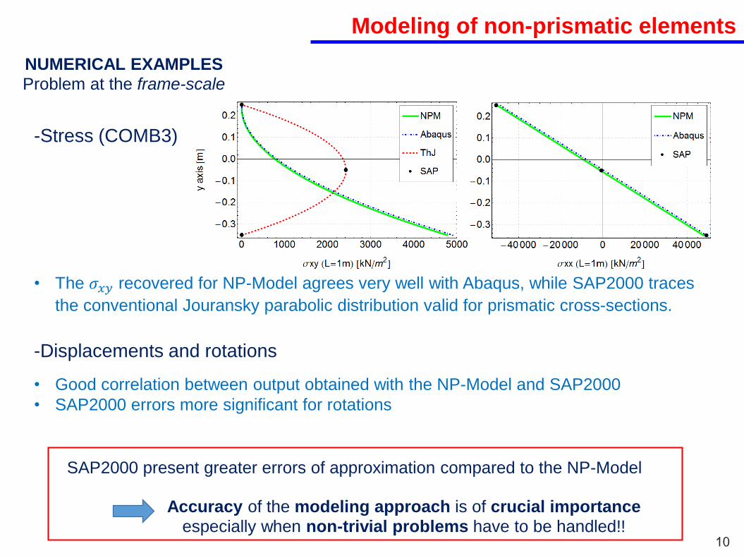
-Displacements and rotations
-Stress (COMB3)
• Good correlation between output obtained with the NP-Model and SAP2000
• SAP2000 errors more significant for rotations
• The 𝜎𝑥𝑦 recovered for NP-Model agrees very well with Abaqus, while SAP2000 traces
the conventional Jouransky parabolic distribution valid for prismatic cross-sections.
SAP2000 present greater errors of approximation compared to the NP-Model
Accuracy of the modeling approach is of crucial importance
especially when non-trivial problems have to be handled!!
NUMERICAL EXAMPLES
Problem at the frame-scale

Manufacturing and optimization methods
11
Project Partners
MATERIALOPTIMIZATION
SHAPE/TOPOLOGYOPTIMIZATION
EXTERNALLY/POST APPLIED REBAR SYSTEM
DESIGN CONCEPT
Novel approach for the fabrication of reinforced
concrete (RC) members based on 3D printing
technology of concrete
Goal of the activity
3D PRINTING PROCESS
CONCRETE MODULUS
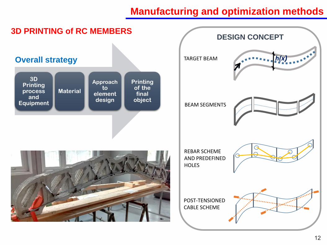
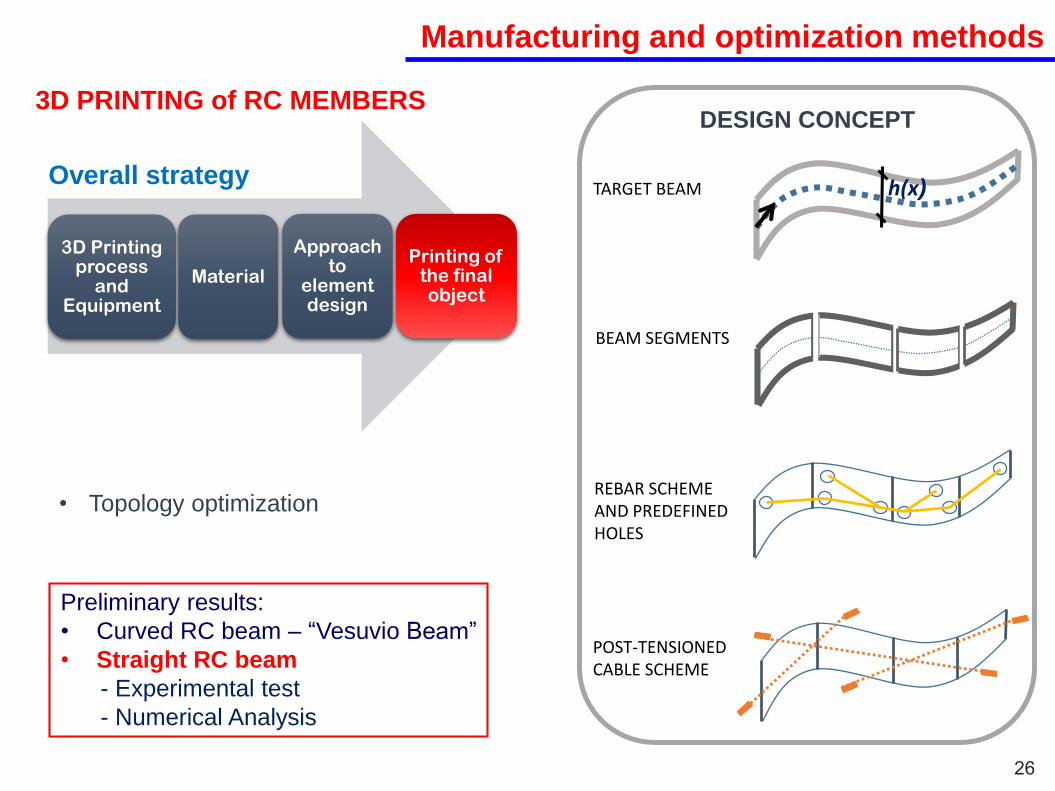
3D PRINTING of RC MEMBERS
Manufacturing and optimization methods
12
3D Printing process
and Equipment
Material
Approachto
element design
Printing of the final
object
Overall strategy h(x)TARGET BEAM
BEAM SEGMENTS
REBAR SCHEME AND PREDEFINED HOLES
POST-TENSIONED CABLE SCHEME
DESIGN CONCEPT3D PRINTING of RC MEMBERS

Manufacturing and optimization methods
12
Topology optimization
h(x)TARGET BEAM
BEAM SEGMENTS
REBAR SCHEME AND PREDEFINED HOLES
POST-TENSIONED CABLE SCHEME
DESIGN CONCEPT
3D Printing process
and Equipment
Material
Approachto
elementdesign
Printing of the final
object
Overall strategy
3D PRINTING of RC MEMBERS

Manufacturing and optimization methods
13
General problem
Ref.: Octaviano Malfavon Farìas, Master Thesis
3D PRINTING
Stl file
TopologyOptimization
flow
Plot of the design
variable (example:
density)
Post-processing
Topology optimization represents a fundamental step for the development of a complete
3D-printing reinforced concrete framework

Manufacturing and optimization methods
14
The application of classical optimization strategies to concrete 3D Printing
is not straightforward!
IMPORTANT ASPECTS
Topology optimization problem
Stress-constraint problem
Stages of the design process
Pre-post processing
Printing material
Concrete – No Von Mises stress
Technology peculiaritiesExtrusion constraints
NEVERTHELESS…
To find optimization strategies
aligned with the proposed 3D
printing approach
MATLAB CODE
OPEN-SOURCE
SOFTWARE
NEW OPTIMIZATION
ALGORITHM
Manufacturing and optimization methods
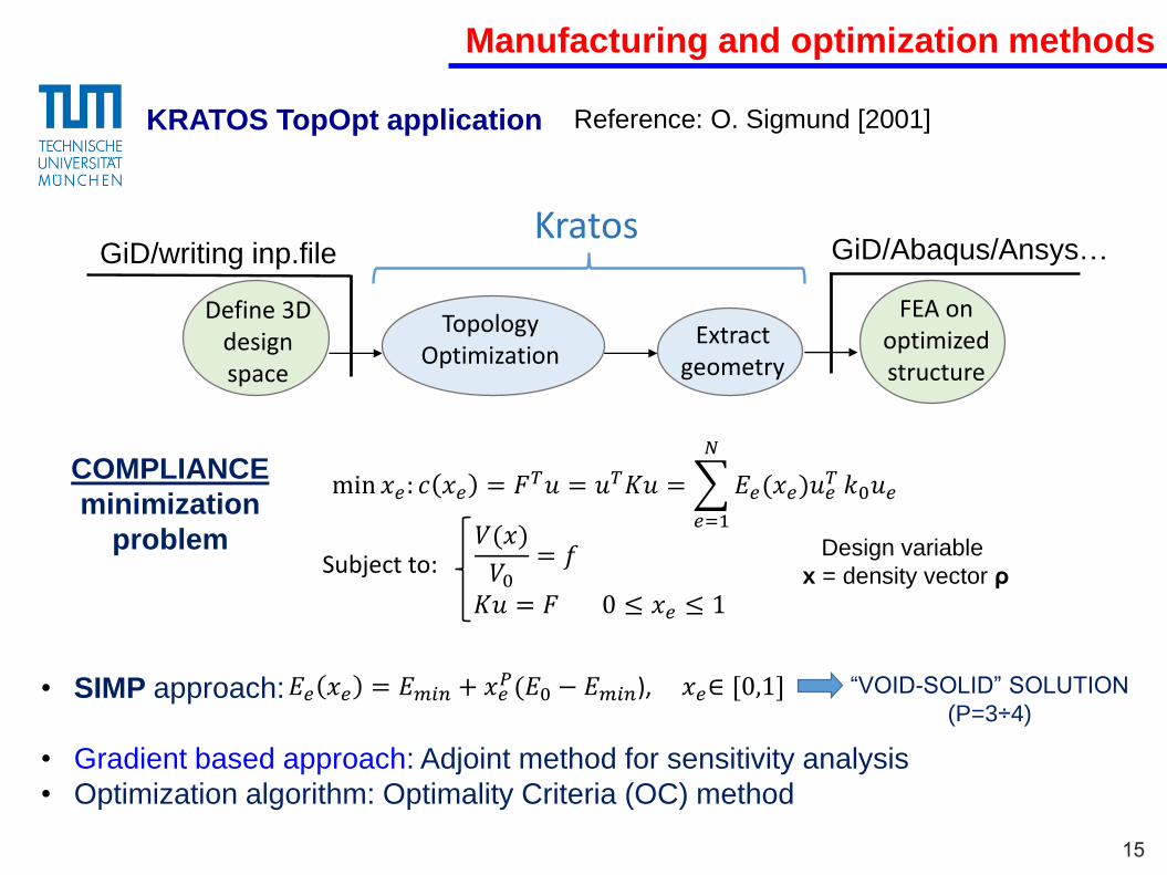
15
• SIMP approach:
• Gradient based approach: Adjoint method for sensitivity analysis
• Optimization algorithm: Optimality Criteria (OC) method
COMPLIANCE
minimization
problem
min 𝑥𝑒: 𝑐 𝑥𝑒 = 𝐹𝑇𝑢 = 𝑢𝑇𝐾𝑢 =
𝑒=1
𝑁
𝐸𝑒(𝑥𝑒)𝑢𝑒𝑇 𝑘0𝑢𝑒
𝑉(𝑥)
𝑉0= 𝑓
𝐾𝑢 = 𝐹 0 ≤ 𝑥𝑒 ≤ 1
𝐸𝑒 𝑥𝑒 = 𝐸𝑚𝑖𝑛 + 𝑥𝑒𝑃(𝐸0 − 𝐸𝑚𝑖𝑛), 𝑥𝑒∈ [0,1]
Define 3D design space
Extractgeometry
FEA on optimizedstructure
KratosGiD/writing inp.file
TopologyOptimization
Design variable
x = density vector ρ
“VOID-SOLID” SOLUTION
(P=3÷4)
Subject to:
Reference: O. Sigmund [2001]
GiD/Abaqus/Ansys…
KRATOS TopOpt application
Manufacturing and optimization methods
16
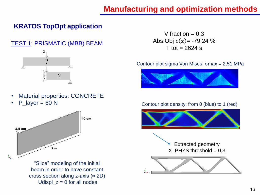
TEST 1: PRISMATIC (MBB) BEAM
• Material properties: CONCRETE
• P_layer = 60 N
“Slice” modeling of the initial
beam in order to have constant
cross section along z-axis (≈ 2D)
Udispl_z = 0 for all nodes
P
Contour plot sigma Von Mises: σmax = 2,51 MPa
Contour plot density: from 0 (blue) to 1 (red)
Extracted geometry
X_PHYS threshold = 0,3
KRATOS TopOpt applicationV fraction = 0,3
Abs.Obj 𝑐 𝑥 = -79,24 %
T tot = 2624 s

Manufacturing and optimization methods
17
TEST 2: VESUVIO BEAM
• Material properties: CONCRETE
• P_layer = 60 N
• “Slice” modeling
P
Contour plot sigma Von Mises: σmax = 1,41 MPa
Contour plot density: from 0 (blue) to 1 (red)
Extracted geometry
X_PHYS threshold = 0,4
KRATOS TopOpt applicationV fraction = 0,4
Abs.Obj 𝑐 𝑥 = -37,78 %
T tot =15478 s

Manufacturing and optimization methods
18
KRATOS TopOpt application
Extracted geometry
STL File
Post-processing
PROS
Stages of the design process OK!
• Capability in handling
complex 3D problems
• Open source software
CONS
Topology optimization problem
Printing material
Technology peculiarities
X
X
X

Manufacturing and optimization methods
19
• SIMP approach:
• Heuristic approach
• Optimization algorithm: Proportional distribution
𝐸𝑒 𝑥𝑒 = 𝐸𝑚𝑖𝑛 + 𝑥𝑒𝑃(𝐸0 − 𝐸𝑚𝑖𝑛), 𝑥𝑒∈ [0,1]
Reference: Biyikli et al. [2015]Matlab code: PSTOpt algorithm (Proportional Topology Optimization approach)
MASS minimization
problem min
𝑖=1
𝑁
𝑥𝑒
Subject to:
𝑲𝒖 = 𝒇𝜎𝑒 < 𝜎𝑙𝑖𝑚
0 < 𝑥𝑚𝑖𝑛 ≤ 𝑥 ≤ 1
Design variable
x = density vector ρ
Design variables assigned to elements
proportionally to the value of stress

Manufacturing and optimization methods
20
Original algorithm
FE and stress analysis
maxσvm – σlim < 0.001 BREAK
IF
ELSE IF
ELSE
maxσvm > σlim
xR=xT
While xR > 0.001
xD(e)= xR(e)∙Cprop(e) ∀𝑒 = 1,… ,𝑁
W filter x(e)
xR=xT- 𝑖𝑁 𝑥𝑒
xT= 𝑖𝑁 𝑥𝑖 + 0.001𝑁
xT= 𝑖𝑁 𝑥𝑖 − 0.001𝑁
Reference: Biyikli et al. [2015]
(Proportional Topology Optimization approach)
q = proportion exponent
𝐶𝑝𝑟𝑜𝑝𝑒 =𝜎𝑣𝑚𝑒
𝑞
𝑒𝑁 𝜎𝑣𝑚𝑒
𝑞
Constraint on theVON MISES STRESSES
Manufacturing and optimization methods
21
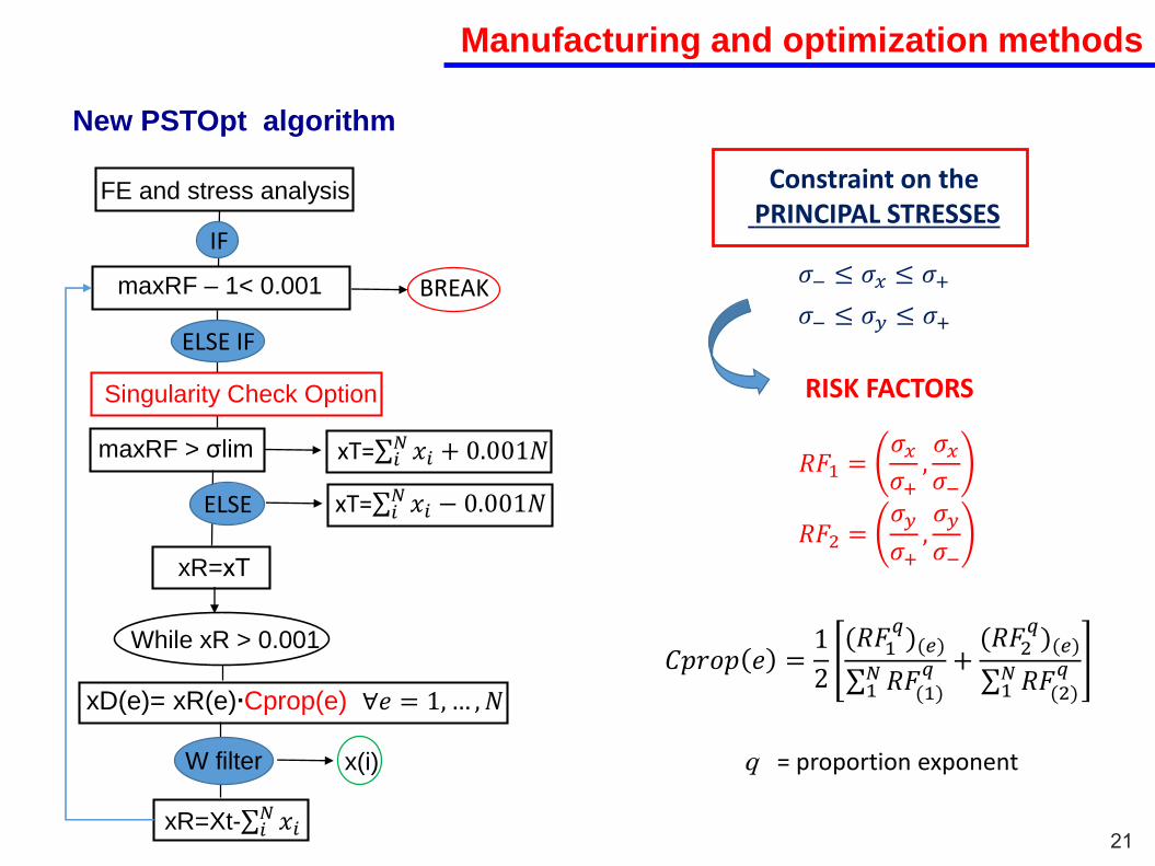
New PSTOpt algorithm
𝜎− ≤ 𝜎𝑥 ≤ 𝜎+
𝜎− ≤ 𝜎𝑦 ≤ 𝜎+
RISK FACTORS
𝑅𝐹1 =𝜎𝑥𝜎+,𝜎𝑥𝜎−
𝑅𝐹2 =𝜎𝑦
𝜎+,𝜎𝑦
𝜎−
q = proportion exponent
𝐶𝑝𝑟𝑜𝑝 𝑒 =1
2 (𝑅𝐹1𝑞)(𝑒)
1𝑁𝑅𝐹(1)
𝑞 + (𝑅𝐹2𝑞)(𝑒)
1𝑁𝑅𝐹(2)
𝑞
Constraint on thePRINCIPAL STRESSES
FE and stress analysis
maxRF – 1< 0.001 BREAK
IF
ELSE IF
ELSE
maxRF > σlim xT= 𝑖𝑁 𝑥𝑖 + 0.001𝑁
xR=xT
While xR > 0.001
xD(e)= xR(e)∙Cprop(e) ∀𝑒 = 1, … ,𝑁
W filter x(i)
xT= 𝑖𝑁 𝑥𝑖 − 0.001𝑁
xR=Xt- 𝑖𝑁 𝑥𝑖
Singularity Check Option

Manufacturing and optimization methods
22
New PSTOpt algorithm
Material properties: CONCRETE
Limit values for the principal stress:𝜎− = −20 𝑁/𝑚𝑚
2
𝜎+ = 1 𝑁/𝑚𝑚2
RESULTS:
N iterations = 616, Time = 324 s, Avg_ρ = 0,26
Mesh = 225x50
𝒖𝒚 𝒎𝒂𝒙𝝈𝟏𝟏 𝒎𝒂𝒙𝝈𝟏𝟐 𝒎𝒂𝒙𝝈𝟐𝟐
-0,30 mm 1,00 Mpa 0,42 Mpa 0,50 Mpa
𝒎𝒂𝒙𝝈𝒑𝒓𝒊𝒏𝒄 𝒎𝒊𝒏𝝈𝒑𝒓𝒊𝒏𝒄
1,00 Mpa -1,93 Mpa
TEST 1: CONCRETE MBB BEAM

Manufacturing and optimization methods
23
New PSTOpt algorithm
Limit values for the principal stress:𝜎− = −20 𝑁/𝑚𝑚
2
𝜎+ = 1 𝑁/𝑚𝑚2
RESULTS:
Mesh = 450x100
𝒖𝒚 𝒎𝒂𝒙𝝈𝟏𝟏 𝒎𝒂𝒙𝝈𝟏𝟐 𝒎𝒂𝒙𝝈𝟐𝟐
-0,27 mm 1,00 Mpa 0,42 Mpa 0,98 Mpa
𝒎𝒂𝒙𝝈𝒑𝒓𝒊𝒏𝒄 𝒎𝒊𝒏𝝈𝒑𝒓𝒊𝒏𝒄
1,00 Mpa -3,05 Mpa
TEST 2: CONCRETE MBB BEAM Material properties: CONCRETE
N iterations = 601, Time = 602 s, Avg_ρ = 0,26
Manufacturing and optimization methods
24
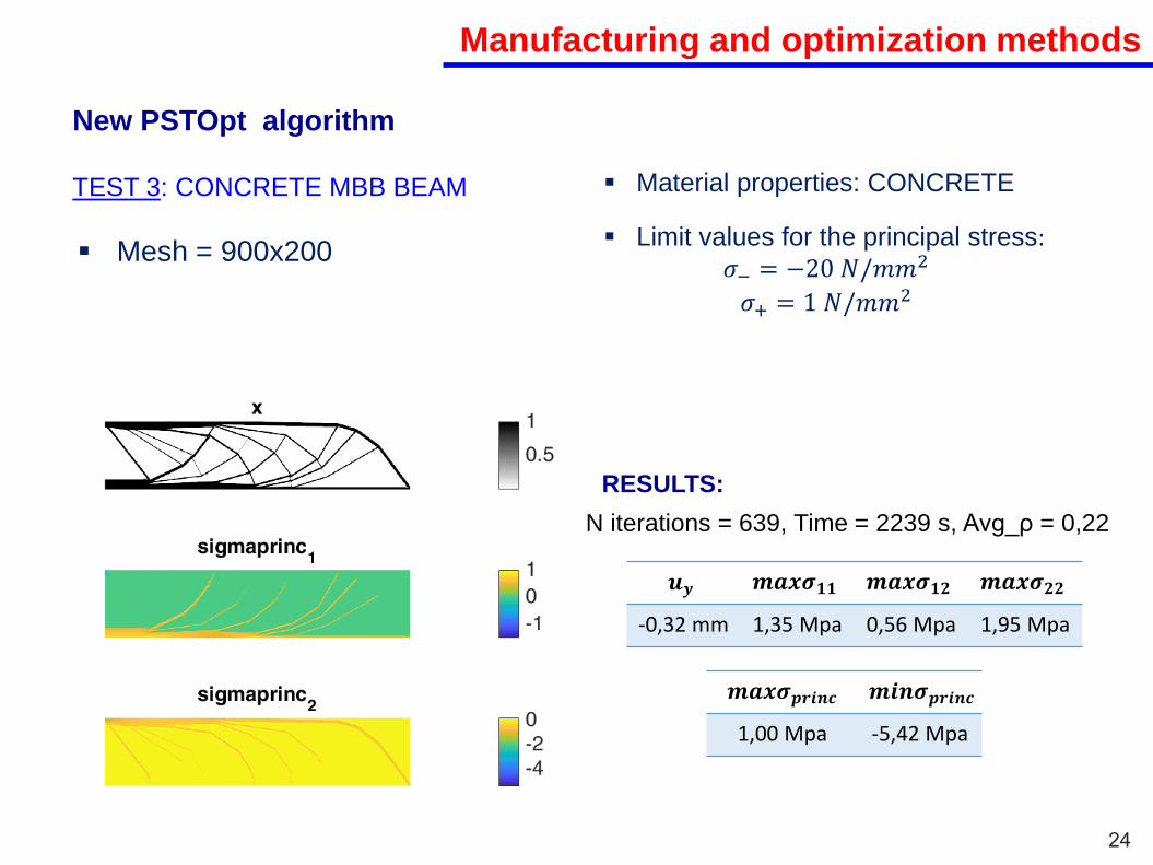
New PSTOpt algorithm
Limit values for the principal stress:𝜎− = −20 𝑁/𝑚𝑚
2
𝜎+ = 1 𝑁/𝑚𝑚2
RESULTS:
N iterations = 639, Time = 2239 s, Avg_ρ = 0,22
Mesh = 900x200
𝒖𝒚 𝒎𝒂𝒙𝝈𝟏𝟏 𝒎𝒂𝒙𝝈𝟏𝟐 𝒎𝒂𝒙𝝈𝟐𝟐
-0,32 mm 1,35 Mpa 0,56 Mpa 1,95 Mpa
𝒎𝒂𝒙𝝈𝒑𝒓𝒊𝒏𝒄 𝒎𝒊𝒏𝝈𝒑𝒓𝒊𝒏𝒄
1,00 Mpa -5,42 Mpa
TEST 3: CONCRETE MBB BEAM Material properties: CONCRETE

Manufacturing and optimization methods
24
New PSTOpt algorithm
Limit values for the principal stress:𝜎− = −20 𝑁/𝑚𝑚
2
𝜎+ = 1 𝑁/𝑚𝑚2
RESULTS:
N iterations = 639, Time = 2239 s, Avg_ρ = 0,22
Mesh = 900x200
𝒖𝒚 𝒎𝒂𝒙𝝈𝟏𝟏 𝒎𝒂𝒙𝝈𝟏𝟐 𝒎𝒂𝒙𝝈𝟐𝟐
-0,32 mm 1,35 Mpa 0,56 Mpa 1,95 Mpa
𝒎𝒂𝒙𝝈𝒑𝒓𝒊𝒏𝒄 𝒎𝒊𝒏𝝈𝒑𝒓𝒊𝒏𝒄
1,00 Mpa -5,42 Mpa
TEST 3: CONCRETE MBB BEAM Material properties: CONCRETE
MICHELL OPTIMUM
STRUCTURES

Manufacturing and optimization methods
25
PROS
Topology optimization problem OK!
Printing material OK!
CONS
Stages of the design process
Technology peculiaritiesX
New PSTOpt algorithm
X
• Only 2D simple problems
• Improvements in the
optimal criteria needed
• Simplicity
Manufacturing and optimization methods
26
• Topology optimization
h(x)TARGET BEAM
BEAM SEGMENTS
REBAR SCHEME AND PREDEFINED HOLES
POST-TENSIONED CABLE SCHEME
DESIGN CONCEPT
3D Printing process
and Equipment
Material
Approach to
element design
Printing of the final object
Overall strategy
3D PRINTING of RC MEMBERS
Preliminary results:
• Curved RC beam – “Vesuvio Beam”
• Straight RC beam
- Experimental test
- Numerical Analysis

Manufacturing and optimization methods
27
SIMPLY SUPPORTED STRAIGHT BEAM UNDER CONCENTRATED LOAD
Simple Bending : Strut and tie model
(no topology optimization)
Bars connector system
Male thread
connector
Hex nut rod
pipe
Possibility to easily compare preliminary
outcomes with classical beam theory results
DISPLACEMENT CONTROL THREE-POINT
BENDING EXPERIMENTAL TEST
NUMERICAL ANALYSIS (SAP2000)
To understand the mechanism of
resistance of a 3D printed RC
beam

Manufacturing and optimization methods
28
EXPERIMENTAL SET UP
• Universal servo-hydraulic testing machine
• Load scheme is set to ensure tensile or
compression primary failure
• Displacement control test
• Load and displacement measurements
made by strain gages
• Velocity = 0,5 mm/min
• Cell load = 500 kN
Strain gages – steel bar
Strain gages – concrete

Manufacturing and optimization methods
NUMERICAL ANALYSIS
o Abaqus
o SAP2000
SAP2000 Simplified model of the straight RC beam
• Load: concentrated force at point A + gravity load
• BCs : simply supported beam (points B and C; Uz = 0 at each node of the mesh
• LINEAR STATIC ANALYSIS
SIMPLIFIED 2D MODEL ADOPTING 1D-FRAME ELEMENTS
Geometric configurations were modified in accordance
with the development of the cracking process
3 different analysis to model the 3 main steps of the cracking formation
29

Manufacturing and optimization methods
EXPERIMENTAL RESULTS
30
Load-deflection curve from experimental data
In terms of overall flexural behaviour it is possible to identify two main stages:
- Linear elastic stage (till point A)
- Non-linear stage (from point A on)
The Non-linear stage can be
itself subdivided into:
- start of cracking stage
(A-B curve)
- progression of cracking stage
(B-C curve)
- final failure stage
(curve from point C on)
Manufacturing and optimization methods
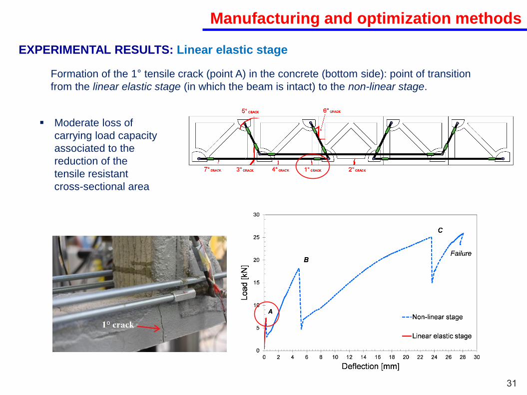
EXPERIMENTAL RESULTS: Linear elastic stage
31
Formation of the 1° tensile crack (point A) in the concrete (bottom side): point of transition
from the linear elastic stage (in which the beam is intact) to the non-linear stage.
Moderate loss of
carrying load capacity
associated to the
reduction of the
tensile resistant
cross-sectional area

Manufacturing and optimization methods
EXPERIMENTAL RESULTS: Start of cracking stage
32
Load increase with an almost linear trend until the formation of the second major crack (point B)
The curve still maintains
a linear slope; the beam
system is still reacting
as a monolithic element
since bars connector
system is preserved

Manufacturing and optimization methods
EXPERIMENTAL RESULTS: Progression of cracking stage
33
Formation of the 3°, 4° and 5° major cracks which do not develop in a distinct manner
not possible to clearly identify which one determines the third peak load (point C).
Complex mechanism of
fracture involving concrete
segments (tensile cracks), the
interface connection surface
(interface opening and relative
sliding), and bars connection
system (shear failure of the
anchoring substrate made of
concrete material).

Manufacturing and optimization methods
EXPERIMENTAL RESULTS: Final failure stage
34
After reaching of the ultimate peak load (point C) severe damage occurs in correspondence of the
connection system between the steel reinforcement and the central concrete segment.
Global failure of the beam

COMPARISON BETWEEN EXPERIMENTAL AND NUMERICAL RESULTS
The behaviour of the
3D printed RC beam
is intermediate
between that of the
Equivalent Solid Beam
and the Equivalent
Cracked beam
Linear elastic stage: load-deflection curves from
experimental data and simulations.
Linear elastic stage
35
Manufacturing and optimization methods

COMPARISON BETWEEN EXPERIMENTAL AND NUMERICAL RESULTS
- start of cracking stage
(A-B curve) the numerical
curve matches quite well the
experimental data
- progression of cracking stage
(B-C curve) the numerical
curve matches quite well the
experimental one until a load
of around 15 kN.
The worsening in the response
prediction is due to the local
effects induced by the strong
non-linear crack mechanism
not captured by the simplified
numerical model.
Load-deflection curves from experimental data and
simulations
Non-linear stage
36
Manufacturing and optimization methods

37
Conclusions
MODELING OF NON-PRISMATIC ELEMENTS
The present thesis wanted both to deepen the performance of numerical methods for the
design of complex shapes and to present an innovative 3D printing method for the production
of RC elements and possible compatible topology optimization tools.
• Common codified methods are often unable to account for the varying section shapes of
non-prismatic elements, suffering of an ineffective modelling capability.
Software SAP2000 VS NP-Model CAUTIOUS MODELING OF
NON-PRISMATIC ELEMENTS
WHIT COMMERCIAL SOFTWARE!
• The discussion of the results has highlighted a good response of the NP-Model
• The simplicity of derivation makes possible the implementation of the NP-Model in
commercial software

38
Conclusions
MANUFACTURING AND OPTIMIZATION METHODS
The present thesis wanted both to deepen the performance of numerical methods for the
design of complex shapes and to present an innovative 3D printing method for the production
of RC elements and possible compatible topology optimization tools.
Topology optimization
• Several issues in the implementation of topology optimization for concrete AM purposes
KRATOS software Stages of the design process
PSTOpt algorithm Topology optimization problem
Printing Material
LACK OF A CODE WICH
COVERS ALL ISSUES +
TECHNOLOGY
PECULIARITIES
3D Printing approach
• Potential of the technology proved in practice by full-scale 3D printed beams and
preliminary outcomes from an experimental activity and numerical analysis.
MORE INVESTIGATIONS ARE NEEDED TO
ADDRESS CRITICAL ISSUES AND EXTEND THE
METHOD TO INNOVATIVE PRACTICAL CASES
Overall ductility
Local failure
Rebar system
…

39
Future developments
• To bring together the achievements obtained, combining the design step (using
the non-prismatic beam model and a renewed topology optimization tool) with
the manufacturing one (presented 3D printing approach) in a real application.
• Printed objects integrated in a real building monitoring over the time.
FUTURE STEPS
SUCCESSFUL IMPLEMENTATION OF AM IN BUILDING INDUSTRY
To distinguish between "printing process" and "building system“
Systematic classification of the available AM concrete-based technologies
and related obtainable products.
To facilitate understanding of concrete 3D printing to engineers and designers.
Targeted research topics: - material
- analytic/numerical method for the calculation
- new proven experimental/statistical data to
support theoretical advances
CHALLENGES

40
Publications
• V. Mercuri, G. Balduzzi, D. Asprone and F. Auricchio. 2D Non-prismatic beam model
for stiffness matrix evaluation. Conference paper from World Conference on Timber
Engineering (WCTE2016), November 2016.
• G. Scalet, E. Boatti, M. Ferraro, V. Mercuri, D. J. Hartl and F. Auricchio, V. Mercuri.
Explicit finite element implementation of a shape memory alloy constitutive model
and associated analyses. Conference paper from XIV International Conference on
Computational Plasticity. Fundamentals and Applications, September 2016.
• V. Mercuri, G. Balduzzi, D. Asprone and F. Auricchio. Non-prismatic planar beam:
stiffness matrix evaluation and application to reinforced concrete frames. Preprint
submitted to International Journal of Advanced Structural Engineering (IJAS) -
Springer, 27 September 2017.
• C. Menna, D. Asprone, F. Auricchio and V. Mercuri. 3D printing of reinforced
concrete elements: technology and design approach. Construction & Building
Materials, 165 (2018): 218-231.

THANKS FOR YOUR ATTENTION!