FORD TRANSIT - giordanobenicchi.it AC/Ford/Manual FORD TRANSIT 2... · descrizione simbologia...
46
FORD TRANSIT 2.4 TDCi "140Hp" EURO 4 Codice/Code:1FO28200E Via Nobili, 2 40062 Molinella (Bologna) - Italy DELPHI ITALIA AUTOMOTIVE SYSTEMS S.r.l. "Stabilimento Molinella" Telefono (0039) 051.6906111 - Fax (0039) 051.6906287 - Email: [email protected] Istruzioni montaggio condizionatore d’aria Air conditioning installation instructions Instructions pour monter le conditionneur d’air Klimaanlage Einbauanleitungen Instrucciones para el montaje del equipo aire acondicionado
Transcript of FORD TRANSIT - giordanobenicchi.it AC/Ford/Manual FORD TRANSIT 2... · descrizione simbologia...
FORD TRANSIT2.4 TDCi "140Hp" EURO 4
Codice/Code:1FO28200E
Via Nobili, 2 40062 Molinella (Bologna) - Italy DELPHI ITALIA AUTOMOTIVE SYSTEMS S.r.l. "Stabilimento Molinella"
Telefono (0039) 051.6906111 - Fax (0039) 051.6906287 - Email: [email protected]
Istruzioni montaggio condizionatore d’aria
Air conditioning installation instructions
Instructions pour monter le conditionneur d’air
Klimaanlage Einbauanleitungen
Instrucciones para el montaje del equipo aire acondicionado
DESCRIZIONE SIMBOLOGIA UTILIZZATA / DESCRIPTION DE LA SYMBOLOGIE UTILISÉEDESCRIPTION OF SYMBOLS USED / BESCHREIBUNG DER VERWENDETEN SYMBOLIK
DESCRIPCIÓN DE LOS SIMBOLOS UTILIZADOS
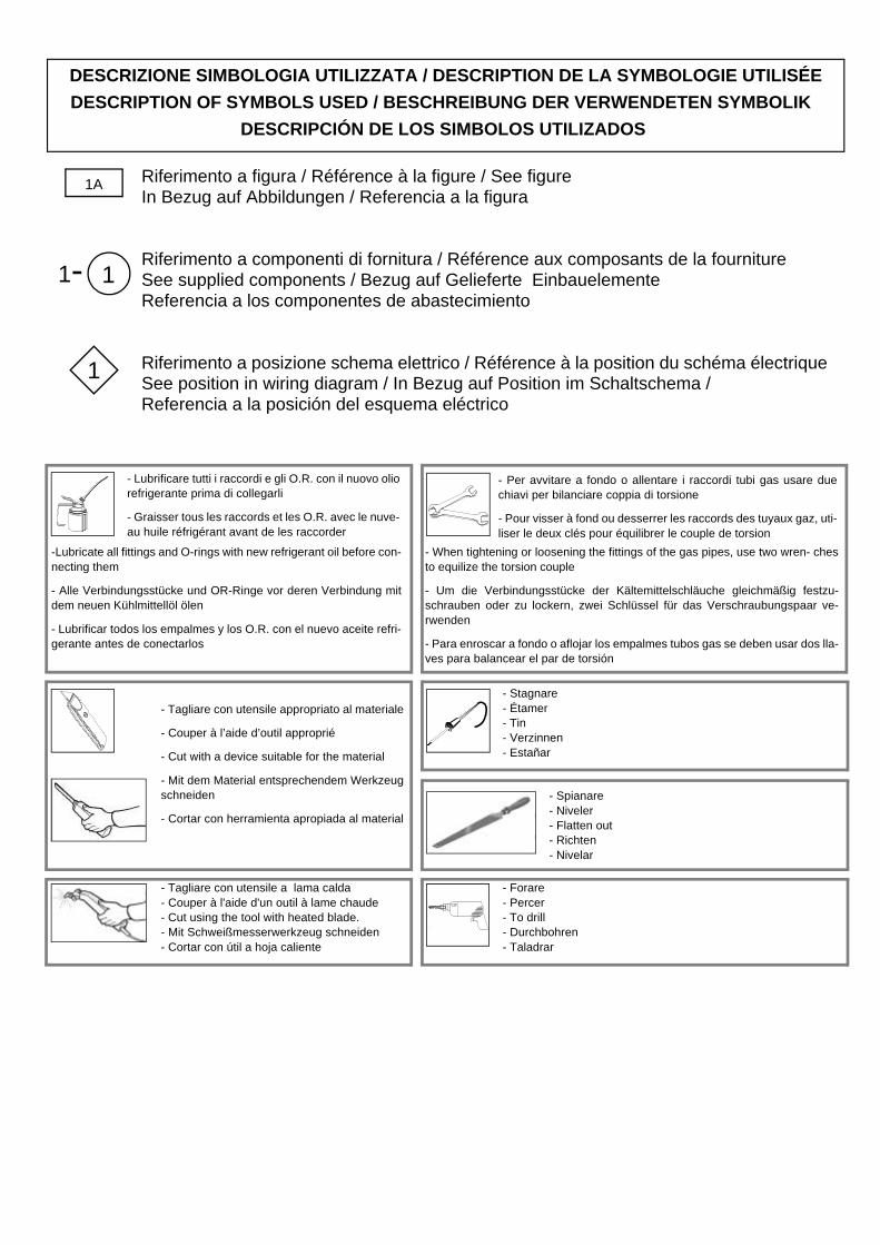
Riferimento a figura / Référence à la figure / See figure In Bezug auf Abbildungen / Referencia a la figura
Riferimento a componenti di fornitura / Référence aux composants de la fournitureSee supplied components / Bezug auf Gelieferte EinbauelementeReferencia a los componentes de abastecimiento
Riferimento a posizione schema elettrico / Référence à la position du schéma électriqueSee position in wiring diagram / In Bezug auf Position im Schaltschema / Referencia a la posición del esquema eléctrico
1A
1
1
- Lubrificare tutti i raccordi e gli O.R. con il nuovo oliorefrigerante prima di collegarli
- Graisser tous les raccords et les O.R. avec le nuve-au huile réfrigérant avant de les raccorder
- Forare- Percer- To drill- Durchbohren- Taladrar
- Tagliare con utensile appropriato al materiale
- Couper à l’aide d’outil approprié
- Cut with a device suitable for the material
- Mit dem Material entsprechendem Werkzeugschneiden
- Cortar con herramienta apropiada al material
- Per avvitare a fondo o allentare i raccordi tubi gas usare duechiavi per bilanciare coppia di torsione
- Pour visser à fond ou desserrer les raccords des tuyaux gaz, uti-liser le deux clés pour équilibrer le couple de torsion
-Lubricate all fittings and O-rings with new refrigerant oil before con-necting them
- Alle Verbindungsstücke und OR-Ringe vor deren Verbindung mitdem neuen Kühlmittellöl ölen
- Lubrificar todos los empalmes y los O.R. con el nuevo aceite refri-gerante antes de conectarlos
- When tightening or loosening the fittings of the gas pipes, use two wren- chesto equilize the torsion couple
- Um die Verbindungsstücke der Kältemittelschläuche gleichmäßig festzu-schrauben oder zu lockern, zwei Schlüssel für das Verschraubungspaar ve-rwenden
- Para enroscar a fondo o aflojar los empalmes tubos gas se deben usar dos lla-ves para balancear el par de torsión
- Stagnare- Étamer- Tin- Verzinnen- Estañar
- Spianare- Niveler- Flatten out- Richten- Nivelar
- Tagliare con utensile a lama calda- Couper à l'aide d'un outil à lame chaude- Cut using the tool with heated blade.- Mit Schweißmesserwerkzeug schneiden- Cortar con útil a hoja caliente
1-

3
Pos. ITALIANO FRANÇAIS ENGLISH DEUTSCH ESPAÑOL
31 Condensatore Condenseur Condenser Kondensator Condensador
32 Sacchetto accessori Sachet accessoires Bag of accessories Säckchen mit Zuberhörteilen
Bolsita accesorio
33 Staffa destra di supporto condensatore
Etrier support condenseur droit
Right condenser support bracket
Kondensator-Haltebügel, rechts
Abrazadera derecha desoporte condensador
34 Staffa sinistra di supporto condensatore
Etrier support condenseur gauche
Left condenser support bracket
Kondensator-Haltebügel, links
Abrazadera izquierda desoporte condensador
35 Elettroventola Electroventilateur Electric fan Elektrogebläse Electroventilador
36Staffa superiore di supporto elettroventola
Etrier supérieur de support électroventilateur
Upper electric fans support bracket
Elektrogebläse-Haltebügel, oben
Abrazadera superior de soporte electroventilador
37Staffa inferiore di supporto elettroventola
Etrier inférieur de support électroventilateur
Lower electric fan support bracket
Elektrogebläse-Haltebügel, unteren
Abrazadera inferior de soporte electroventilador
38 Piastrina di rinforzo elettroventola
Plaque de renforce-ment électroventila-teur
Electric fan reinfor-cing plate
Elektrogebläse-Zusa-tzträger
Plaquita de refuerzo electroventilador
39 Guarnitura adesiva Garniture adhésive Adhesive seal Klebedichtung Guarnición adhesiva40 Tubo acqua Tuyau à eau Water pipe Wasserschlauc Tubo de agua
40.1 Fascetta Collier Clamp Schelle Banda
41 Tubo servofreno Tuyau servofrein Power brake hose Servobremsenschlauch Tubo servofreno
41.1 Raccordo adattatoreper tubo aria
Raccord adaptateurpour tuyau d'air
Connection adapterfor air hose Anschlußpassungsstück Rácor adaptador para
tubo aire41.2 Tubo aria Tuyau de l’air Air pipe Luftschlauch Tubo del aire
42 Sacchetto fissaggiotubi gas
Sachet fixation tujauxgaz
Bag of gas pipe secu-ring elements
Säckchen mit Kälte-mittelschlauch-Befe-stigung
Bolsita sujeción tubosgas
42.1 Flangia tubi gas Bride tuyaux gaz Gas pipe flange Kältemittelschlauch-flansch
Brida tubos gas
43 Mastice anticondensa Mastic anti-condensation
Condensation-proofing material
Kondenserwasserdi-chtemasse
Masilla anticondensación
44 Staffa di supporto tubi gas
Etrier support destuyaux gaz
Gas pipe supportbracket
Kältemittelschlauch-Haltebügel
Abrazadera desoporte tubos gas
45 Fascetta fermatuboφ 20 con perno
Collier de fixage tuyauφ20 avec pivot
Hose fixing clampφ 20 with pin
Schlauch-Halteschel-le φ 20 mit Bolzen
Abrazadera deretenedor tubo φ 20con perno
46 Protezione a spirale Protection en spirale Spiral protection Spiralförmige Ummantelung Protección a espiral
47 Copri-relais Couvre-relais Relay cover Relais-Verkleidung Cubre-realais 51 Filtro essiccatore Filtre déshydrateur Receiver drier Trocknerfilter Filtro secador52 Staffa filtro Etrier filtre Receiver drier bracket Filterbügel Abrazadera filtro53 Pressostato Pressostat Pressure switch Druckwächter Presostato61 Gruppo climatizzatore Groupe climatiseur Climate control unit Heizklimagerät Grupo climatizador62 Condotto aria centrale Conduit d'air central Central air duct Zentraler Luftschacht Conducto aire central
63 Condotto aria Defrostdestro
Conduit d'air Defrostdroit Right Defrost air duct Rechter Defrost-
LuftschachtConducto aireDeshielo derecho
64 Condotto aria Defrostsinistro
Conduit d'air Defrostgauche Left Defrost air duct Linker Defrost-
LuftschachtConducto aire Deshielo izquierdo
65 Condotto aria internodestro
Conduit d'air internedroit Inner right air duct Rechter
InnenluftschachtConducto aire interiorderecho
66 Condotto aria internosinistro
Conduit d'air internegauche Inner left air duct Linker
InnenluftschachtConducto aire interiorizquierdo
67 Sacchetto accessori Sachet accessoires Bag of accessories Säckchen mit Zuberhörteilen
Bolsita accesorio
68 Termostato Thermostat Thermostat Thermostat Termostato
69 Staffa supportotermostato
Etrier supportthermostat
Thermostat supportbracket
Thermostat-Haltebügel Abrazadera soportetermostato
70 Molla fissaggio bulbo Ressort fixage bulbeThermoswitch fixingspring
Kolben-befestigung-sfeder
Muelle de fijiacióndelbulbo
71 Rompigoccia Brise-gouttes Drip-guard Tropfenleiste Rompegotas

4
Pos. ITALIANO FRANÇAIS ENGLISH DEUTSCH ESPAÑOL
72 Tubo gas preformato(5/16")
Tuyau gaz préformé(5/16")
Preformed gas hose(5/16")
Vorgeformter Kaeltemittelschlauch(5/16")
Tubo gas preformado(5/16")
73 Tubo gas preformato(1/2")
Tuyau gaz préformé(1/2")
Preformed gas hose(1/2")
Vorgeformter Kaeltemittelschlauch(1/2")
Tubo gas preformado(1/2")
74 Molletta fissatubi(5/16")
Ressort fixation destuyaux (5/16")
Hose securing spring(5/16")
Schlauch-Befestigungsklemme(5/16")
Tenacilla detiene tubos (5/16")
75 Molletta fissatubi(1/2")
Ressort fixation destuyaux (1/2")
Hose securing spring(1/2")
Schlauch-Befestigungsklemme(1/2")
Tenacilla detiene tubos (1/2")
76 Valvola di espansione Soupape d’expansion Expansion valve Expansionsventil Válvula expansión
77 Flangia fissaggio valvola
Bride de fixagesoupape Valve fixing flange Ventil-Befestigungs-
flansch Brida de fijación de la válvula
77.1 Vite speciale TCE Vis spéciale à têtecylindrique
Special hexagonalhead screw
Spezial-Sechskant Zylinderschraube
Tornillo especialcabeza cilíndrica conhexágono
106 Impianto elettrico Installation électrique Electric system Elektrische Anlage Instalación eléctrica
107Giunzione RAYCHEMROSSA
Raccord RAYCHEMROUGE
RED RAYCHEM connector
RAYCHEM Verbindung ROT
Junta RAYCHEMROJO
108ConnettorePACKARD 1 via
ConnecteurPACKARD à 1 voie
1-way PACKARDconnector
1-Weg-PACKARD-Steckverbinder
Conector PACKARD1 vía
109ConnettorePACKARD 5 vie
ConnecteurPACKARD à 5 voies
5-way PACKARDconnector
5-Weg-PACKARD-Steckverbinder
Conector PACKARD5 vías
110110.1
Cablaggio supplementare
Câblage supplémentaire Supplementary wiring Zusatz-Kabelstrang Cableado
suplementario
115Impianto elettropneumaticoBY-PASS
Faisceauélectro-pneumatiqueBY-PASS
Electropneumatic BY-PASS system
BY-PASSUnterdruckanlage
InstalaciónelectroneumáticoBY-PASS
116 Rubinetto by-pass Bypass cock Robinet by-pass By-Pass Ventil Llave by-pass
117 Gommino Pièce en caoutchouc / Rubber lead Gummizwischenlage Goma
118 Fascetta Collier Clamp Schelle Banda
119 Valvola solenoide Soupape solénoide Solenoid valve Solenoidventil Válvula solenoide
120121 Raccordo ad Y Raccord en Y Y-connection Y-Anschluß Empalme Y
122 Valvola unidirezionale Soupapeunidirectionnelle Unidirectional valve Sperrventil Vàlvula unidireccional
Tubo gas 5/16"CF (condensatore-filtro)
Tuyau gaz 5/16"CF (condenseur-filtre)
5/16"CF gas hose(condenser-filter)
5/16"CFkaeltemittelschlauch (Kondensator-Filter)
Tubo gas 5/16"CF (condensador-filtro)
Tubo gas 5/16"FE (filtro-evaporatore)
Tuyau gaz 5/16"FE(filtre-évaporateur)
5/16"FE gas hose(filter-evaporator)
5/16"FEkaeltemittelschlauch(Filter-Verdampfer)
Tubo gas 5/16"FE(filtro-evaporador)
Tubo gas 13/32"CC(compressore-condensatore)
Tuyau gaz 13/32"CC(compresseur-condenseur)
13/32"CC gas hose(compressor-condenser)
13/32"CC kaeltemittelschlauch(Kompressor-Kondensator)
Tubo gas 13/32"CC(compresor-condensador)
Tubo gas 1/2"EC (evaporatore-compressore)
Tuyau gaz 1/2"EC (évaporateur-compresseur)
1/2"EC gas hose (evaporator-compressor)
1/2"ECkaeltemittelschlauch(Verdampfer-Kompressor)
Tubo gas 1/2"EC (evaporador-compresor)
K Raccordo con puntodi carica
Raccord avec point decharge
Charge point connection
Verbindungsstück mitFüllpunkt
Racor con punto decarga
Fascetta a strappo Bride auto-bloquant Self-locking clamp SelbstsicherndeSchelle
Banda autobloqueante

5
Pos. Descrizione / Description / DescriptionBeschreibung / Descripción
Codice / Code Kode / Codigo
31 Condensatore 022301OR/1A
32 Sacchetto accessori 0231847/0
33 Staffa destra di supporto condensatore 0812889/0
34 Staffa sinistra di supporto condensatore 0812890/0
35 Elettroventola 080135.1
36 Staffa superiore di supporto elettroventole 0811912/0
37 Staffa inferiore di supporto elettroventola 0811423/0
38 Piastrina di rinforzo elettroventola 036124.1
39 Guarnitura adesiva 070036/0
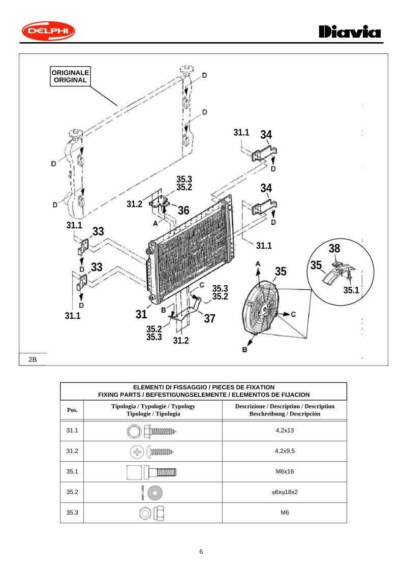
MONTAGGIO CONDENSATORE / POSE DU CONDENSEUR / CONDENSER FITTINGKONDENSATOREINBAU / MONTAJE CONDENSADOR
MATERIALE FORNITO / MATERIEL FOURNI / SUPPLIED MATERIAL / GELIEFERTES MATERIAL / MATERIAL ABASTECIDO
1B
39
36
32
31
35
33 34
38
37
6
ELEMENTI DI FISSAGGIO / PIECES DE FIXATIONFIXING PARTS / BEFESTIGUNGSELEMENTE / ELEMENTOS DE FIJACION
Pos.Tipologia / Typologie / Typology
Tipologie / TipologiaDescrizione / Description / Description
Beschreibung / Descripción
31.1 4,2x13
31.2 4,2x9,5
35.1 M6x16
35.2 φ6xφ18x2
35.3 M6
2B
31
34
36
37
33
35
383533
3431.1
31.1
31.1
31.1
31.2
31.2
35.135.335.2
35.235.3
35.335.2
ORIGINALEORIGINAL
7
3B
36
31
33
34
34
33
37
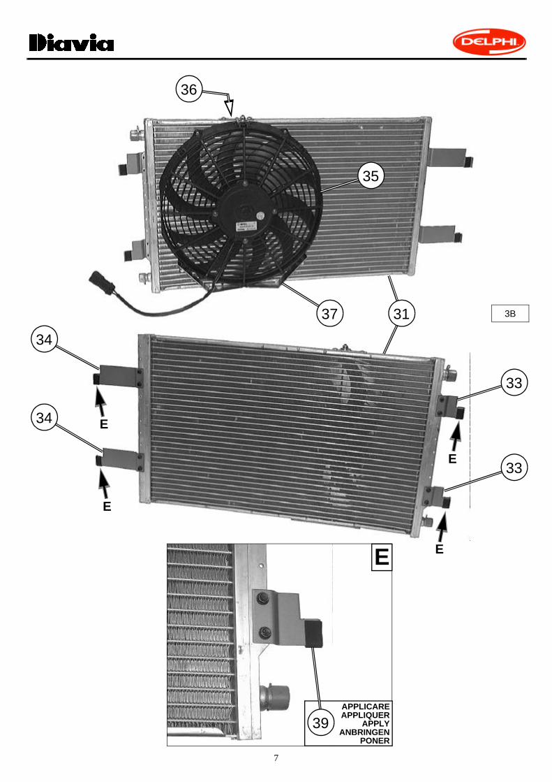
APPLICAREAPPLIQUER
APPLYANBRINGEN
PONER
39
35
E
E
E
E
E

8
4B
3135
34
INSERIRE AD INCASTROINSERER PAR EMBOITEMENT
TO INSERT TO JOINTEINKLEMMEN
INSERIR A ENCASTRE
33
9
Pos.Descrizione / Description
Description / BeschreibungDescripción
Codice / CodeKode / Codigo
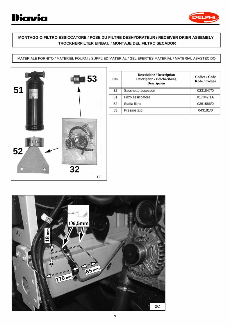
32 Sacchetto accessori 0231847/0
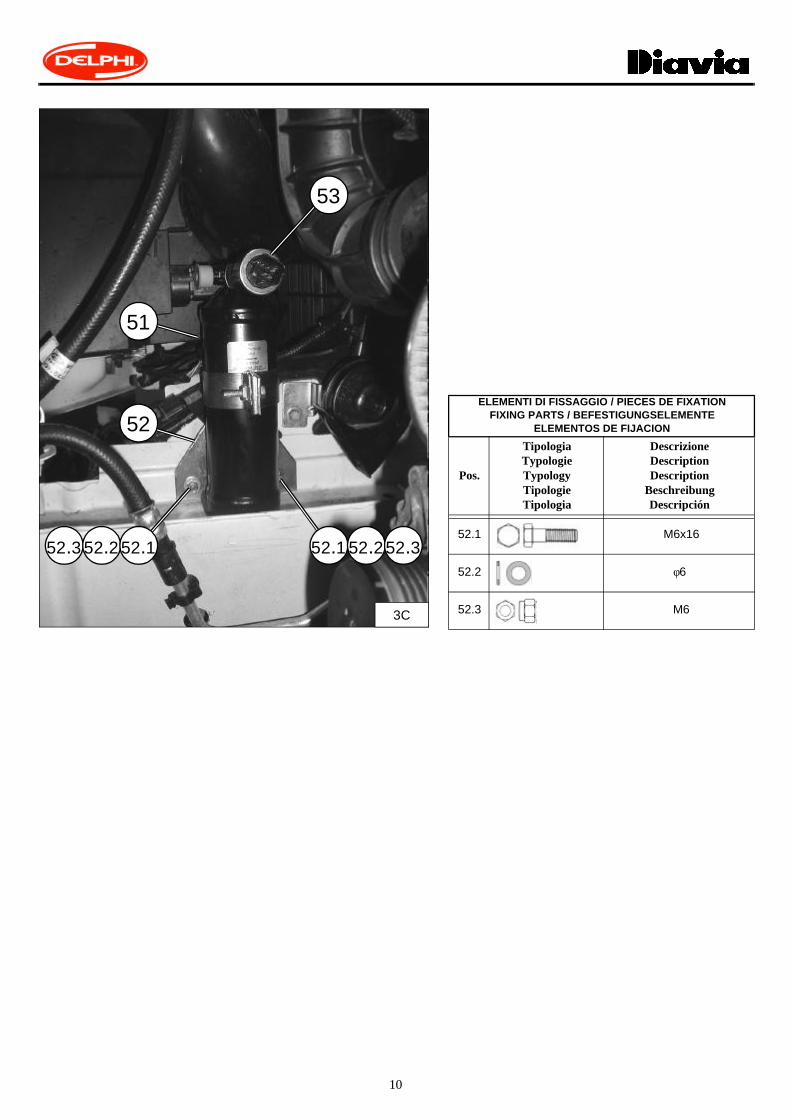
51 Filtro essiccatore 017047/1A
52 Staffa filtro 0361586/0
53 Pressostato 043181/0
MONTAGGIO FILTRO ESSICCATORE / POSE DU FILTRE DESHYDRATEUR / RECEIVER DRIER ASSEMBLY TROCKNERFILTER EINBAU / MONTAJE DEL FILTRO SECADOR
MATERIALE FORNITO / MATERIEL FOURNI / SUPPLIED MATERIAL / GELIEFERTES MATERIAL / MATERIAL ABASTECIDO
52
5153
321C
2C
18 m
m
170 mm85 mm
φ6,5mm
10
51
ELEMENTI DI FISSAGGIO / PIECES DE FIXATIONFIXING PARTS / BEFESTIGUNGSELEMENTE
ELEMENTOS DE FIJACION
Pos.
TipologiaTypologieTypologyTipologieTipologia
DescrizioneDescriptionDescription
BeschreibungDescripción
52.1 M6x16
52.2 φ6
52.3 M63C
53
52
52.152.252.352.352.252.1
11
Pos.Descrizione / Description
Description / Beschreibung Descripción
Codice / CodeKode / Codigo
(FORD)
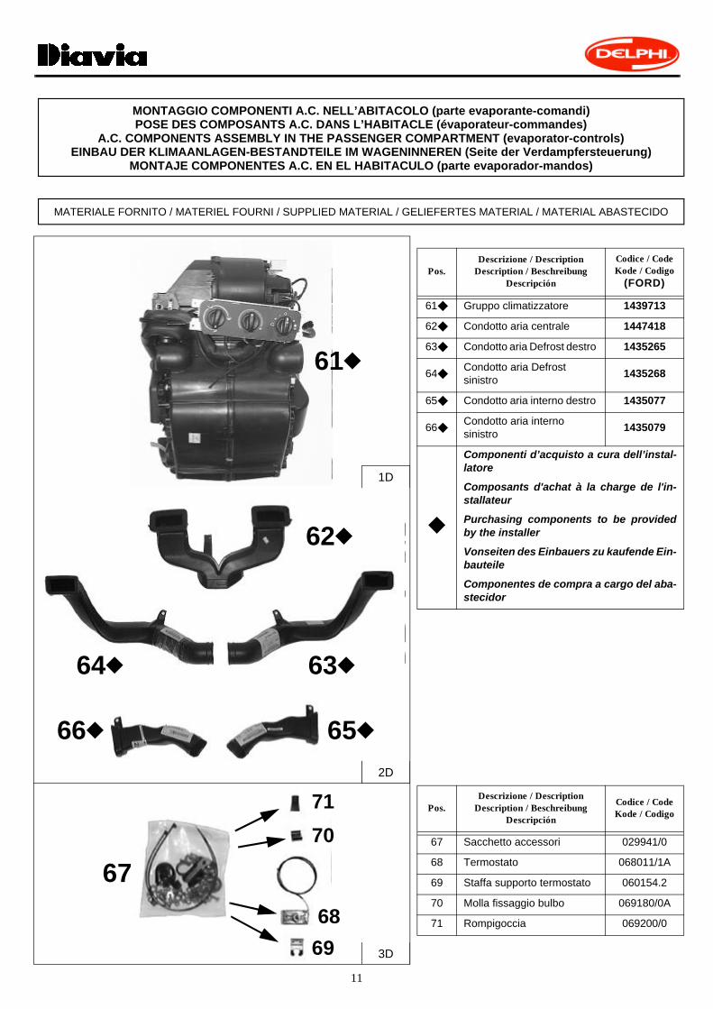
61u Gruppo climatizzatore 1439713
62u Condotto aria centrale 1447418
63u Condotto aria Defrost destro 1435265
64uCondotto aria Defrostsinistro
1435268
65u Condotto aria interno destro 1435077
66uCondotto aria internosinistro
1435079
u
Componenti d’acquisto a cura dell’instal-latore
Composants d'achat à la charge de l'in-stallateur
Purchasing components to be providedby the installer
Vonseiten des Einbauers zu kaufende Ein-bauteile
Componentes de compra a cargo del aba-stecidor
Pos.Descrizione / Description
Description / Beschreibung Descripción
Codice / Code Kode / Codigo
67 Sacchetto accessori 029941/0
68 Termostato 068011/1A
69 Staffa supporto termostato 060154.2
70 Molla fissaggio bulbo 069180/0A
71 Rompigoccia 069200/0
MONTAGGIO COMPONENTI A.C. NELL’ABITACOLO (parte evaporante-comandi)POSE DES COMPOSANTS A.C. DANS L’HABITACLE (évaporateur-commandes)
A.C. COMPONENTS ASSEMBLY IN THE PASSENGER COMPARTMENT (evaporator-controls)EINBAU DER KLIMAANLAGEN-BESTANDTEILE IM WAGENINNEREN (Seite der Verdampfersteuerung)
MONTAJE COMPONENTES A.C. EN EL HABITACULO (parte evaporador-mandos)
MATERIALE FORNITO / MATERIEL FOURNI / SUPPLIED MATERIAL / GELIEFERTES MATERIAL / MATERIAL ABASTECIDO
62
61
63
67
71
65
69
70
68
70
3D
2D
u
62u
64u 63u
66u 65u
2D
1D
71

12
Pos.Descrizione / Description
Description / BeschreibungDescripción
CodiceCode / Kode
Codigo
106 Impianto elettrico 0282471/1
107 Giunzione RAYCHEM ROSSO 064274/0
110 Cablaggio supplementare -
110.1 Cablaggio supplementare -
MATERIALE FORNITO / MATERIEL FOURNI / SUPPLIED MATERIAL / GELIEFERTES MATERIAL / MATERIAL ABASTECIDO
106
0282471/1
110
110.1
4D
107107
13
OPERAZIONI PRELIMINARI / OPERATIONS PRELIMINAIRES / PRELIMINARY OPERATIONSVORBEREITUNGSARBEITEN / OPERACIONES PRELIMINARES
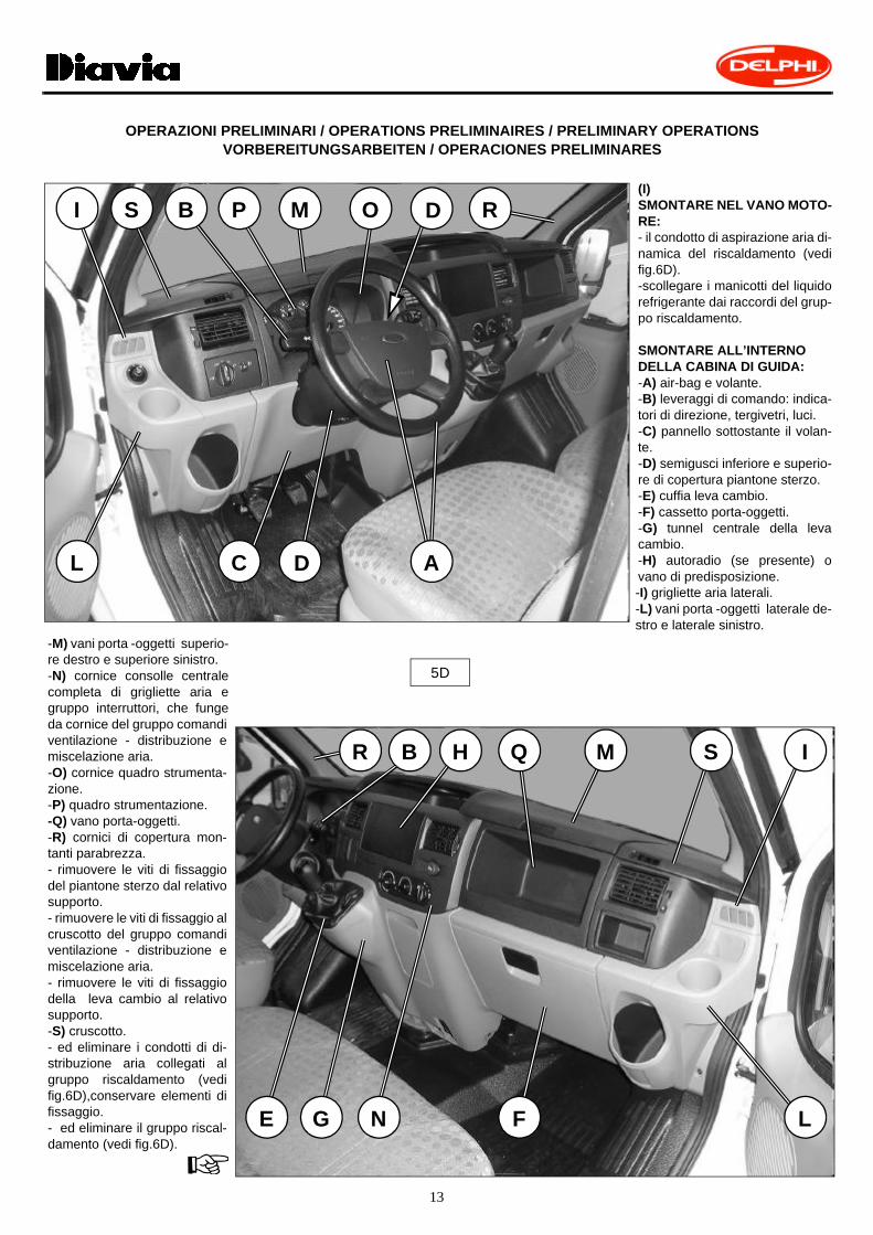
(I)SMONTARE NEL VANO MOTO-RE:- il condotto di aspirazione aria di-namica del riscaldamento (vedifig.6D).-scollegare i manicotti del liquidorefrigerante dai raccordi del grup-po riscaldamento.
SMONTARE ALL’INTERNO DELLA CABINA DI GUIDA:-A) air-bag e volante.-B) leveraggi di comando: indica-tori di direzione, tergivetri, luci.-C) pannello sottostante il volan-te.-D) semigusci inferiore e superio-re di copertura piantone sterzo.-E) cuffia leva cambio.-F) cassetto porta-oggetti.-G) tunnel centrale della levacambio.-H) autoradio (se presente) ovano di predisposizione.-I) grigliette aria laterali.-L) vani porta -oggetti laterale de-stro e laterale sinistro.
-M) vani porta -oggetti superio-re destro e superiore sinistro.-N) cornice consolle centralecompleta di grigliette aria egruppo interruttori, che fungeda cornice del gruppo comandiventilazione - distribuzione emiscelazione aria.-O) cornice quadro strumenta-zione.-P) quadro strumentazione.-Q) vano porta-oggetti.-R) cornici di copertura mon-tanti parabrezza.- rimuovere le viti di fissaggiodel piantone sterzo dal relativosupporto.- rimuovere le viti di fissaggio alcruscotto del gruppo comandiventilazione - distribuzione emiscelazione aria.- rimuovere le viti di fissaggiodella leva cambio al relativosupporto.-S) cruscotto.- ed eliminare i condotti di di-stribuzione aria collegati algruppo riscaldamento (vedifig.6D),conservare elementi difissaggio.- ed eliminare il gruppo riscal-damento (vedi fig.6D).
5D
AC D
E FG
B HR
R
I
I
L
L
M
M
N
OB P
Q S
S D
14
FIG.5D
OPERAZIONI PRELIMINARI / OPERATIONS PRELIMINAIRES / PRELIMINARY OPERATIONSVORBEREITUNGSARBEITEN / OPERACIONES PRELIMINARES
(F)DÉPOSER DANS LE COMPARTIMENT MOTEUR :- le conduit d'aspiration d'air dynamique du chauffage (voir fig.6D).- déconnecter les manchons du liquide réfrigérant des raccordsdu groupe chauffage.
DÉPOSER A L'INTÉRIEUR DE LA CABINE DE CONDUITE:-A) air-bag et le volant.-B) groupe leviers de commande: feux de direction, vitres électri-ques, feux.-C) panneau au dessous du volant.-D) semi-coques inférieure et supérieure de protection de la co-lonne de direction.-E) protection pour levier de changement de vitesse.-F) boîte à gants.-G) tunnel central du levier de changement de vitesse.-H) autoradio ou compartiment prévu.-I) bouches d'air latérales.-L) vide-poches latéral droit et latéral gauche.-M) vide-poches supérieur droit et supérieur gauche.-N) cadre console centrale avec grille d'air et groupe interrupteurs,qui sert de cadre au groupe commandes ventilation - distributionet mélange d'air.-O) cadre du tableau des instruments.-P) tableau de commandes.-Q) compartiment vide-poche.-R) cadres de protection des montants pare-brise.- enlever les fixations de la colonne de direction de son support.-S) tableau de bord.- et éliminer les conduits de distribution d'air reliés au groupechauffage (voir fig.6D), conserver les pièces de fixage.- et éliminer le groupe chauffage (voir fig.6D).
(GB)REMOVE IN THE ENGINE COMPARTMENT:- the dynamic heating air intake duct (see fig. 6D).- disconnect the refrigerant pipe from the connection on the hea-ting unit.
REMOVE FROM INSIDE THE DRIVING CABIN:-A) air-bag and the steering wheel.-B) control levers for directionals, windshield wipers, headlights.-C) panel under the steering wheel.-D) lower and upper halves of the steering column cover.-E) gear lever guard.-F) glove compartment.-G) central shift stick consol.-H) radio (if there is one) or arranged radio housing space.-I) side air vents.-L) right and left side shelves. -M) upper right and upper left shelves. -N) central console frame including air vents and switch assembly,this frame serves as frame for fan - air distribution - air mixing con-trol unit.-O) instrument panel frame.-P) instrument panel.-Q) glove compartmen.-R) frames covering the windshield side posts.- remove the steering column securing elements from their supports.-S) dashboard.- and eliminate the air distribution ducts connected to the heatingunit (see fig. 6). Keep securing elements.- and eliminate the heating unit (see fig. 6D).

15
FIG.5D
OPERAZIONI PRELIMINARI / OPERATIONS PRELIMINAIRES / PRELIMINARY OPERATIONSVORBEREITUNGSARBEITEN / OPERACIONES PRELIMINARES
(E)DESMONTAR EN EL ESPACIO MOTOR:- el conducto de aspiración de aire dinámico de la calefacción(véase fig.6D).- desconectar los manguitos del líquido refrigerante del los raco-res del grupo de calefacción.
DESMONTAR AL INTERIOR DE LA CABINA DECONDUCCIÓN:-A) bolsa neumática y el volante.-B) mecanismo de palancas de mando: indicadores de dirección,limpiaparabrisas, luz.-C) panel situado bajo el volante.-D) semicascos inferior y superior de cobertura columna de dirección.-E) funda palanca de cambio.-F) guantera.-G) túnel central de la palanca de velocidades.-H) radioreceptor (si presente) o espacio de predisposición.-I) rejillas aire laterales.-L) espacios guantera lateral derecha y lateral izquierda.-M) espacios guantera superior derecha y superior izquierda.-N) marco consola central dotada de rejillas aire y grupo interrup-tores, que hace de marco del grupo de mandos ventilación -distribución y mezcla aire.-O) marco tablero de instrumentos.-P) cuadro de instrumentación.-Q) espacio guantera.-R) marcos de cobertura montantes limpiaparabrisas.- quitar las fijaciones de la columna de dirección del soporte cor-respondiente.-S) tablero.- y eliminar los conductos de distribución aire conectados al grupocalefacción (véase fig.6D), conservar los elementos de fijación.- y eliminar el grupo calefacción (véase fig.6D).
(D)IM MOTORRAUM AUSBAUEN:- ansaugschacht der Frischluft der Heizung (siehe Abb.6D).-die Kühlmittelmuffen von den Verbindungsstücken der Heizung-seinheit abklemmen.
IM INNEREN DER FÜHRERKABINE FOLGENDE TEILEAUSBAUEN:-A) air-Bag und Lenkrad.-B) steuerungshebelsystem: Winker, Scheibenwischer, Lichter.-C) füllwand unter dem Lenkrad.-D) untere und obere Gehäusehälfte der Lenksäulenabdeckung.-E) ganghebelabdeckung.-F) handschuhkasten.-G) konsole des Getriebehebels.-H) autoradio (wo vorhanden) oder vorgesehenen Raum.-I) seitliche Luftdüsen.-L) seitlichen Ablage rechts und links.-M) oberen rechten und linken Ablage.-N) des Rahmen der Mittelkonsole komplett mit Lüftungsgitter undSchaltergruppe, dieser dient als Rahmen der Belüftungssteue-rung-Verteilung und Luftmischung.-O) reahmen der Instrumententafel.-P) Instrumentenbrett.-Q) handschuhkastens.-R) abdeckungsrahmen der Windschutzscheibensäulen.- befestigungen der Lenkradsäule von der entsprechenden Halte-rung entfernen.-S) armaturenbrett.- und Entfernung der an der Heizgruppe angeschlossenen Luf-tverteilungsschächte (siehe Abb 6D), Befestigungselemente auf-bewahren.- Heizgruppe (siehe Abb. 6D) entfernen.
6D
ELIMINAREELIMINERDISCARD
ENTFERNENELIMINAR
ELIMINAREELIMINERDISCARD
ENTFERNENELIMINAR
ELIMINAREELIMINERDISCARD
ENTFERNENELIMINAR
ELIMINAREELIMINERDISCARD
ENTFERNENELIMINAR
SMONTAREDEMONTER
REMOVEAUSBAUEN
DESMONTAR
16
7D
ASPORTAREDETACHER
REMOVEENTFERNEN
QUITAR
φ27mm
φ27mm
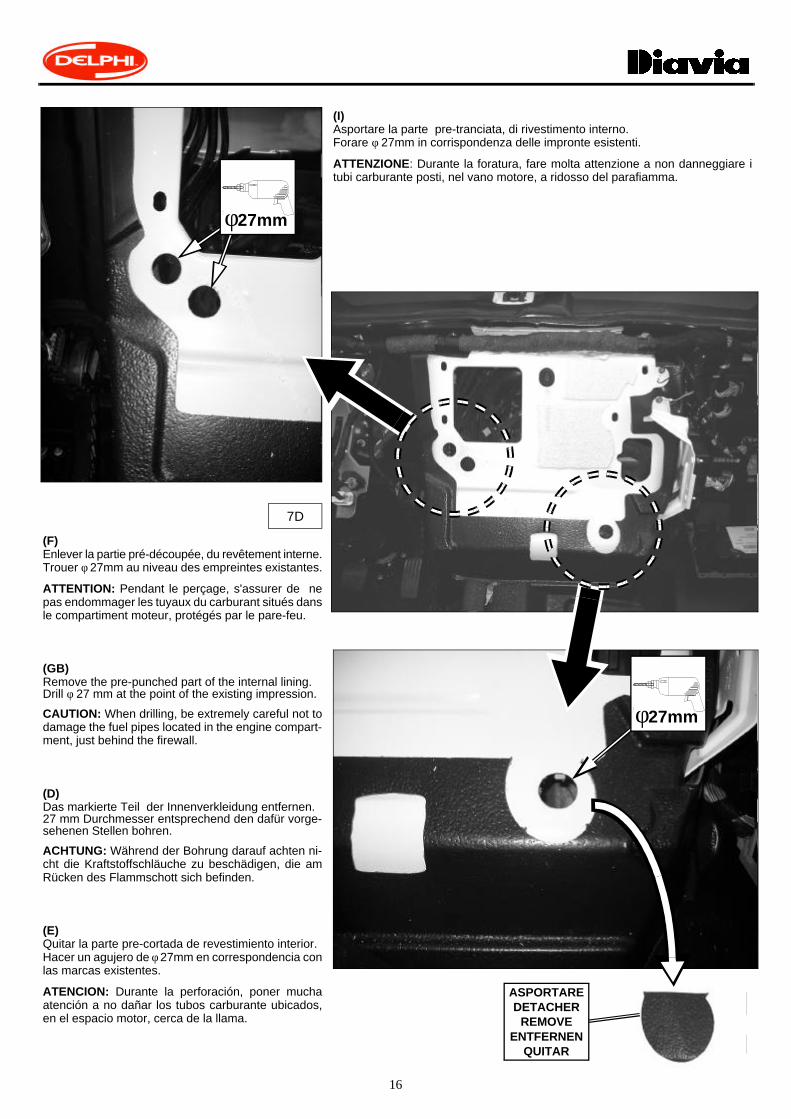
(I)Asportare la parte pre-tranciata, di rivestimento interno.Forare φ 27mm in corrispondenza delle impronte esistenti.
ATTENZIONE: Durante la foratura, fare molta attenzione a non danneggiare itubi carburante posti, nel vano motore, a ridosso del parafiamma.
(F)Enlever la partie pré-découpée, du revêtement interne.Trouer φ 27mm au niveau des empreintes existantes.
ATTENTION: Pendant le perçage, s'assurer de nepas endommager les tuyaux du carburant situés dansle compartiment moteur, protégés par le pare-feu.
(GB)Remove the pre-punched part of the internal lining. Drill φ 27 mm at the point of the existing impression.
CAUTION: When drilling, be extremely careful not todamage the fuel pipes located in the engine compart-ment, just behind the firewall.
(D)Das markierte Teil der Innenverkleidung entfernen.27 mm Durchmesser entsprechend den dafür vorge-sehenen Stellen bohren.
ACHTUNG: Während der Bohrung darauf achten ni-cht die Kraftstoffschläuche zu beschädigen, die amRücken des Flammschott sich befinden.
(E)Quitar la parte pre-cortada de revestimiento interior.Hacer un agujero de φ 27mm en correspondencia conlas marcas existentes.
ATENCION: Durante la perforación, poner muchaatención a no dañar los tubos carburante ubicados,en el espacio motor, cerca de la llama.

17
ELEMENTI DI FISSAGGIO / PIECES DE FIXATION / FIXING PARTSBEFESTIGUNGSELEMENTE / ELEMENTOS DE FIJACION
Pos.Tipologia / TypologieTypology / Tipologie
Tipologia
Descrizione / DescriptionDescription / Beschreibung
Descripción
lORIGINALEORIGINALS
61
8D
62
61
l
62
18
9D
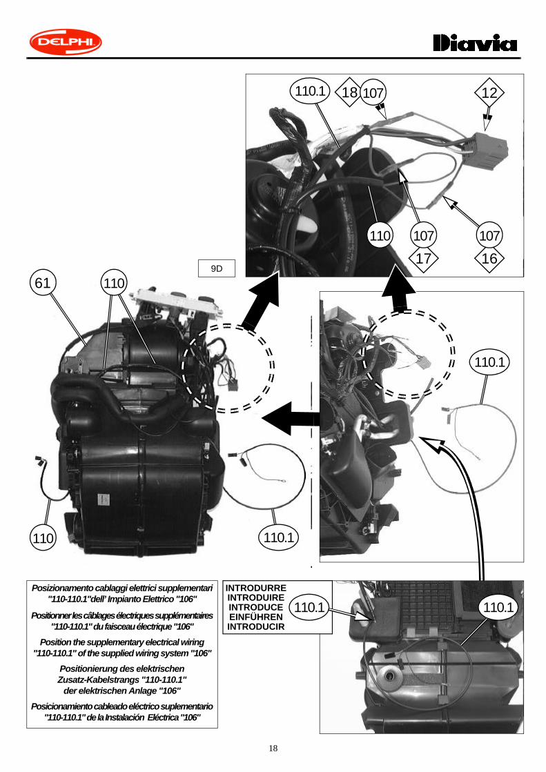
Posizionamento cablaggi elettrici supplementari "110-110.1"dell’ Impianto Elettrico "106"
Positionner les câblages électriques supplémentaires "110-110.1" du faisceau électrique "106"
Position the supplementary electrical wiring "110-110.1" of the supplied wiring system "106"
Positionierung des elektrischenZusatz-Kabelstrangs "110-110.1"
der elektrischen Anlage "106"
Posicionamiento cableado eléctrico suplementario "110-110.1" de la Instalación Eléctrica "106"
16
110 107
17
107
12110.1 18 107
61
110.1110
110.1
INTRODURREINTRODUIREINTRODUCEEINFÜHRENINTRODUCIR
110.1 110.1
110

19
10D
ELEMENTI DI FISSAGGIO / PIECES DE FIXATION / FIXING PARTSBEFESTIGUNGSELEMENTE / ELEMENTOS DE FIJACION
Pos.Tipologia / TypologieTypology / Tipologie
Tipologia
Descrizione / DescriptionDescription / Beschreibung
Descripción
69.1 4x10
(D)Bügel "69" an Thermostat "68" mit vorhandenen Muttern befesti-gen. Das Endteil des Thermostatfühlers "So" mit Gerät φ 6mm, wiein der Abbildung sichtbar umwickeln.
(E)Fijar la abrazadera "69" al termostato "68", mediante tuercas pre-dispuestas. Envolver la parte terminal de la sonda termostato "So",utilizando herramienta φ 6mm, como se ve en la figura.
69
68
70
=
φ 6mm
61
70
69 68
68.1
(I)Fissare la staffa "69" al termostato "68", mediante dadi predispo-sti. Avvolgere la parte terminale della sonda termostato "So", uti-lizzando attrezzo φ 6mm, come visibile in figura.
(F)Fixer l'étrier "69" au thermostat "68", à l'aide des écrous prédispo-sés. Enrouler la partie finale de la sonde du thermostat "So", aumoyen de l'outil φ 6mm, comme indiqué sur la figure.
(GB)Secure bracket "69" to thermostat "68" using thearranged nuts. Using the special φ6mm tool, windthe terminal portion of the thermostat probe "So"as indicated in the figure
61
So
So14
110

20
61
(D)Heizklimagerät "61" und die Luftschächte"63-64-65-66" am Armaturenbrett anbauen undmit aufbewahren Original-Elementen wieder fe-stschrauben. Mit dem Wiedereinbau der Armatu-renbrett-Heizklimagerät-Schachteinheit insFahrzeug fortschreiten.
(E)Montar el grupo climatizador "61" y los con-ductos de aire "63-64-65-66" en el tablero y blo-quearlos con los elementos originalesconservados. Después, volver a montar elconjunto tablero-climatizador-conductos en elvehículo.
6665
(I)Montare il gruppo climatizzatore "61" e i condottiaria "63-64-65-66" sul cruscotto, bloccandoli me-diante elementi originali conservati. Procedere al ri-monaggio dell’assieme cruscotto-climatizzatore-condotti sul veicolo.
(F)Monter le groupe climatisation "61" et les conduitsd'air "63-64-65-66" sur le tableau de bord, en lesbloquant à l'aide des pièces d'origine conservées.Procéder au remontage de l'ensemble tableau debord -climatiseur- conduits sur le véhicule.
(GB)Install the climate control unit "61" and air ducts"63-64-65-66" on the dashboard, locking them inplace with the original securing elements which hadbeen set aside. Finish by reinstalling the dashboard-climate control unit-ducts in the vehicle.
63 64
110.1
65
61
63
ORIGINALEORIGINAL
ORIGINALEORIGINAL
64
ORIGINALEORIGINAL
ORIGINALEORIGINAL
66
61
11D

21
12D
61
61.261.1
ELEMENTI DI FISSAGGIO PIECES DE FIXATION
FIXING PARTS BEFESTIGUNGSELEMENTEELEMENTOS DE FIJACION
Pos.
Tipologia TypologieTypologyTipologieTipologia
DescrizioneDescriptionDescription
BeschreibungDescripción
61.1 M6x30
61.2 φ6xφ24x2
61.3 M6
110.1 61RICOLLEGARERECONNECTER
RECONNECT
VOLVER A CONECTARWIEDER ANSCHLIEßEN
INSERIREINSERER
TO INSERTEINFÜGEN
INSERIR
71
61.261.3
Vista dall’interno dell’abitacoloVue de l’intérieur de l’habitacle
View from inside the passenger’s compartmentInnenansicht des Fahrzeuginnenraums
Vista desde el interior de habitaculo
Vista dal vano motoreVue dans le compartiment moteur
View from the engine compartment Ansicht vom Motorraum Vista del espacio motor
Vista dal vano motoreVue dans le compartiment moteur
View from the engine compartment Ansicht vom Motorraum Vista del espacio motor

22
(I)Rimontare all’interno dell’abitacolo tutti i componenti originali smontati in precedenza.
(F) Réposer dans l'habitacle tous les composants d'origine démontés.
(GB)Reassemble all the original components in the passenger compartment.
(D)Alle vorher ausgebauten Originalbestandteile wieder im Fahrzeuginneren einbauen.
(E)Volver a montar en el interior del habitáculo todos los componentes originales desmontados anteriormente.
13D
61 A.C.

23
Pos.Descrizione / Description
Description / BeschreibungDescripción
CodiceCode / Kode
Codigo
67 Sacchetto accessori 029941/0
72 Tubo gas preformato (5/16") 820E219
73 Tubo gas preformato (1/2") 820E220
74 Molletta fissatubi (5/16") 0691257/0
75 Molletta fissatubi (1/2") 0691256/1
76 Valvola di espansione 058027/0A
77 Flangia fissaggio valvola 043060/0A
77.1 Vite speciale TCE M5x35 105290/0
Pos.Descrizione / Description
Description / BeschreibungDescripción
CodiceCode / Kode
Codigo
32 Sacchetto accessori 0231847/0
40 Tubo acqua 011010.3
40.1 Fascetta 12-22/9 0361740/0
41 Tubo servofreno 0691566/0
41.1 Raccordo adattatore per tubo aria 008537/0
41.2 Tubo aria 0691568/0
42 Sacchetto fissaggio tubi gas 043066/1A
43 Mastice anticondensa 0701407/0
44 Staffa di supporto tubi gas 036210/0
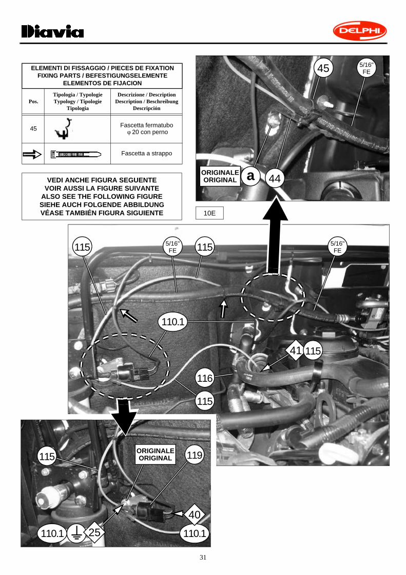
45 Fascetta fermatubo φ 20 con perno 069715/0
46 Protezione a spirale 070494/0
47 Copri-relais 0361070/0
COLLEGAMENTO TUBI GASINSTALLAZIONE IMPIANTO ELETTRICO DIAVIA FRIGO E COMPONENTI ELETTRICI NEL VANO MOTORE
RACCORDEMENT DES TUYAUX GAZINSTALLATION FAISCEAU ELECTRIQUE DIAVIA FRIGO ET COMPOSANTS ELECTRIQUES DANS LE COMPARTIMENT MOTEUR
GAS HOSES CONNECTIONDIAVIA FRIGO ELECTRIC SYSTEM AND ELECTRIC COMPONENTS INSTALLATION IN THE ENGINE COMPARTMENT
ANSCHLUSS DER KÄLTEMITTELSCHLÄUCHEEINBAU DER DIAVIA FRIGO-ELEKTROANLAGE UND DER ELEKTROBESTANDTEILE IM MOTORRAUM
CONEXIÓN DE LOS TUBOS DEL GASINSTALACIÓN ELÉCTRICA DIAVIA FRIGO Y LOS COMPONENTES ELÉCTRICOS EN EL COMPARTIMENTO DEL MOTOR
MATERIALE FORNITO / MATERIEL FOURNI / SUPPLIED MATERIAL / GELIEFERTES MATERIAL / MATERIAL ABASTECIDO
1.1E
32
77
40
67
72 7374
75
76
77.1
40.1
41
41.1 41.2
47
42
434445
1E
46
24
Pos.Descrizione / Description
Description / BeschreibungDescripción
CodiceCode / Kode
Codigo
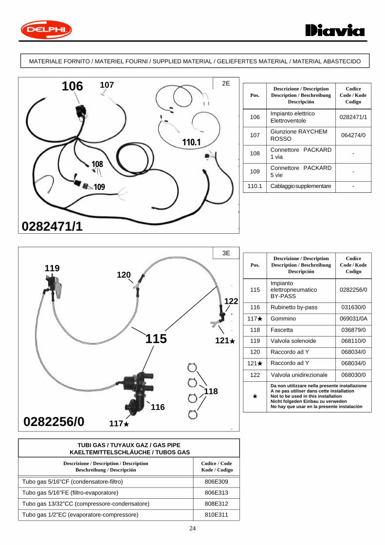
106Impianto elettrico Elettroventole
0282471/1
107Giunzione RAYCHEMROSSO
064274/0
108Connettore PACKARD1 via -
109Connettore PACKARD5 vie
-
110.1 Cablaggio supplementare -
Pos.Descrizione / Description
Description / BeschreibungDescripción
CodiceCode / Kode
Codigo
115ImpiantoelettropneumaticoBY-PASS
0282256/0
116 Rubinetto by-pass 031630/0
117H Gommino 069031/0A
118 Fascetta 036879/0
119 Valvola solenoide 068110/0
120 Raccordo ad Y 068034/0
121H Raccordo ad Y 068034/0
122 Valvola unidirezionale 068030/0
H
Da non utilizzare nella presente installazioneA ne pas utiliser dans cette installationNot to be used in this installation Nicht folgeden Einbau zu verweden No hay que usar en la presente instalación
TUBI GAS / TUYAUX GAZ / GAS PIPE KAELTEMITTELSCHLÄUCHE / TUBOS GAS
Descrizione / Description / DescriptionBeschreibung / Descripción
Codice / Code Kode / Codigo
Tubo gas 5/16"CF (condensatore-filtro) 806E309
Tubo gas 5/16"FE (filtro-evaporatore) 806E313
Tubo gas 13/32"CC (compressore-condensatore) 808E312
Tubo gas 1/2"EC (evaporatore-compressore) 810E311
MATERIALE FORNITO / MATERIEL FOURNI / SUPPLIED MATERIAL / GELIEFERTES MATERIAL / MATERIAL ABASTECIDO
106 107
0282471/1
2E
108
109
110.1
116
0282256/0
118
117H
119120
121H115
3E
122

25
5/16"FE
4E
5/16"FE
1/2"EC
5/16"CF
13/32"CC
13/32"CC 1/2"
EC
13/32"CC
ALL’EVAPORATOREA L’EVAPORATEUR
TO THE EVAPORATORZUM VERDEMPFERAL EVAPORADOR
a K
(I)Vista complessiva passaggio tubi gas nel vano motore.Alla posizione "a" é evidenziato il punto di fissaggio tubo gas 5/16"FE alla vettura, descritto inparticolare nella figura 10E . Alle posizioni "K" sono evidenziate le valvole di carica dell’impiantoaria condizionata predisposte sui raccordi tubi gas 1/2"EC e 5/16"FE.
(F)Vue d’ensemble du passage des tuyaux gaz dans le compartiment moteur.A la pos. "a" on a indiqué le point de fixation du tuyau gaz 5/16"FE à la voiture détaillé sur lafig.10E. Aux pos. "K" on a indiqué les soupapes de charge équipement A/C prévues sur lesraccords des tuyaux gaz 1/2"EC et 5/16"FE.
(GB)General view of the gas hoses in the engine compartment.In the point "a", the 5/16"FE gas hose fixing point to the car is shown 10E. At the position "K",the A/C system charge valves prepared on the 1/2"EC and 5/16"FE gas hoses couplings areshown.
(D)Gesamtansicht des Durchgangs der Kältemittelschläuche im Motorraum. An der Position "a" ist der Befestigungspunkt des 5/16"FE-Kältemittelschlauches im Fahrzeugsichtbar und im Detail in der Abbildung 10E beschrieben. An den Positionen "K" sind die Füll-ventile der Klimaanlage an den Anschlüssen der 1/2"EC und 5/16"FE-Kältemittelschläuchenhervorgehoben.
(E)Vista total paso tubos gas en el compartimiento motor.En la posición "a" está evidenciado el punto de fijación tubo gas 5/16"FE en el coche, descritodetalladamente en la figura 10E. En las posiciones "K" están evidenciadas las válvulas de car-ga de la instalación aire acondicionado preparados en los racord tubos gas 1/2"EC y 5/16"FE.
R134a Kg.0,800(±0,025)

26
POSIZIONAMENTO IMPIANTO ELETTRICO NEL VANO MOTORE (vedi schema elettrico allegato) POSITIONNEMENT DU FAISCEAU ELECTRIQUE DANS LE COMPARTIMENT MOTEUR (voir schéma électrique joint)
POSITIONING THE ELECTRIC SYSTEM WIRING WITHIN THE ENGINE COMPARTMENT (see the enclosed wiring diagram)POSITIONIERUNG DER ELEKTRISCHEN ANLAGE IM MOTORRAUM (siehe Schaltschema im Anhang)
COLOCACIÓN DE LA INSTALACIÓN ELÉCTRICA EN EL ESPACIO MOTOR (véase esquema eléctrico adjunto)
29
5E
25
33A
19
30
22-2321
2433
27
34
42
32A32B
32
106
25
40
18
1617
14
VEDI Fig. 10E-14E-16E-17E-18E-19E-20E-21E-22E-23E-24EVOIR Fig. 10E-14E-16E-17E-18E-19E-20E-21E-22E-23E-24ESEE Fig. 10E-14E-16E-17E-18E-19E-20E-21E-22E-23E-24E
SIEHE Abb. 10E-14E-16E-17E-18E-19E-20E-21E-22E-23E-24EVÉASE Fig. 10E-14E-16E-17E-18E-19E-20E-21E-22E-23E-24E
106 0282471/1

27
6E
BLOCCARE AD INCASTROBLOQUER PAR EMBOITEMENT
TO BLOCK TO JOINTFESTKLEMMEN
BLOQUEAR A ENCASTRE
75
73
72
74
7776
ELEMENTI DI FISSAGGIO / PIECES DE FIXATIONFIXING PARTS / BEFESTIGUNGSELEMENTE
ELEMENTOS DE FIJACION
Pos.
Tipologia TypologieTypologyTipologieTipologia
DescrizioneDescriptionDescription
BeschreibungDescripción
CodiceCodeKode
Codigo
77 Flangia fissaggio valvola 043060/0A
77.1 Vite specialeM5x35 105290/0
77.1
BLOCCARE AD INCASTROBLOQUER PAR EMBOITEMENT
TO BLOCK TO JOINTFESTKLEMMEN
BLOQUEAR A ENCASTRE
28
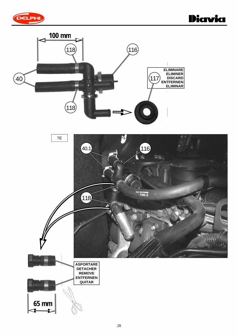
118
118
7E
40
116
100 mm
ELIMINAREELIMINERDISCARD
ENTFERNENELIMINAR
117
40.1 116
ASPORTAREDETACHER
REMOVEENTFERNEN
QUITAR
65 mm
118

29
8E
1/2"EC
1/2"EC
5/16"FE 42.3
42.2
42.1
5/16"FE
76
76
RIVESTIRERHABILLERRECLOTHE
WIEDER EINKLEIDENVOLVER A VESTIR
43
5/16"FE
ELEMENTI DI FISSAGGIO / PIECES DE FIXATION FIXING PARTS / BEFESTIGUNGSELEMENTE
ELEMENTOS DE FIJACION
Pos.
Tipologia Typologie Typology TipologieTipologia
DescrizioneDescriptionDescription
BeschreibungDescripción
Codice Code Kode
Codigo
42.1 Flangia tubi gas 043061/1A
42.2 M6x16 -
42.3 φ 6 -
30
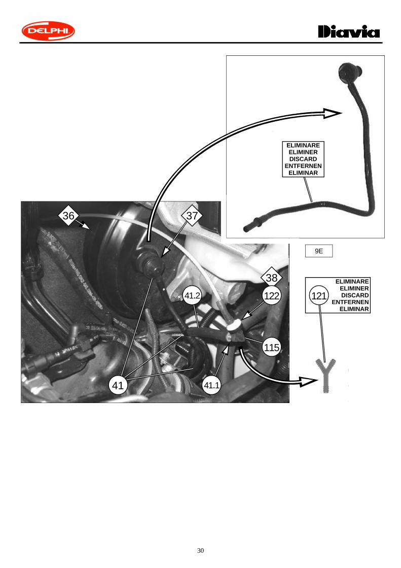
9E
ELIMINAREELIMINERDISCARD
ENTFERNENELIMINAR
115
41.1
41.2
41
ELIMINAREELIMINERDISCARD
ENTFERNENELIMINAR
121
38
122
36 37
31
10E
41 115
5/16"FE
5/16"FE
5/16"FE45
44ORIGINALEORIGINAL a
ELEMENTI DI FISSAGGIO / PIECES DE FIXATIONFIXING PARTS / BEFESTIGUNGSELEMENTE
ELEMENTOS DE FIJACION
Pos.Tipologia / TypologieTypology / Tipologie
Tipologia
Descrizione / DescriptionDescription / Beschreibung
Descripción
45 Fascetta fermatubo φ 20 con perno
Fascetta a strappo
VEDI ANCHE FIGURA SEGUENTEVOIR AUSSI LA FIGURE SUIVANTE
ALSO SEE THE FOLLOWING FIGURESIEHE AUCH FOLGENDE ABBILDUNGVÉASE TAMBIÉN FIGURA SIGUIENTE
ORIGINALEORIGINAL
110.1110.1
119
25
40
110.1
116
115115
115
115

32
11E
ORIGINALEORIGINAL
115
116119
115115 115
115
39
41116
120
115

33
12E
51
5/16"CF
5/16"FE
5/16"FE
5/16"FE51
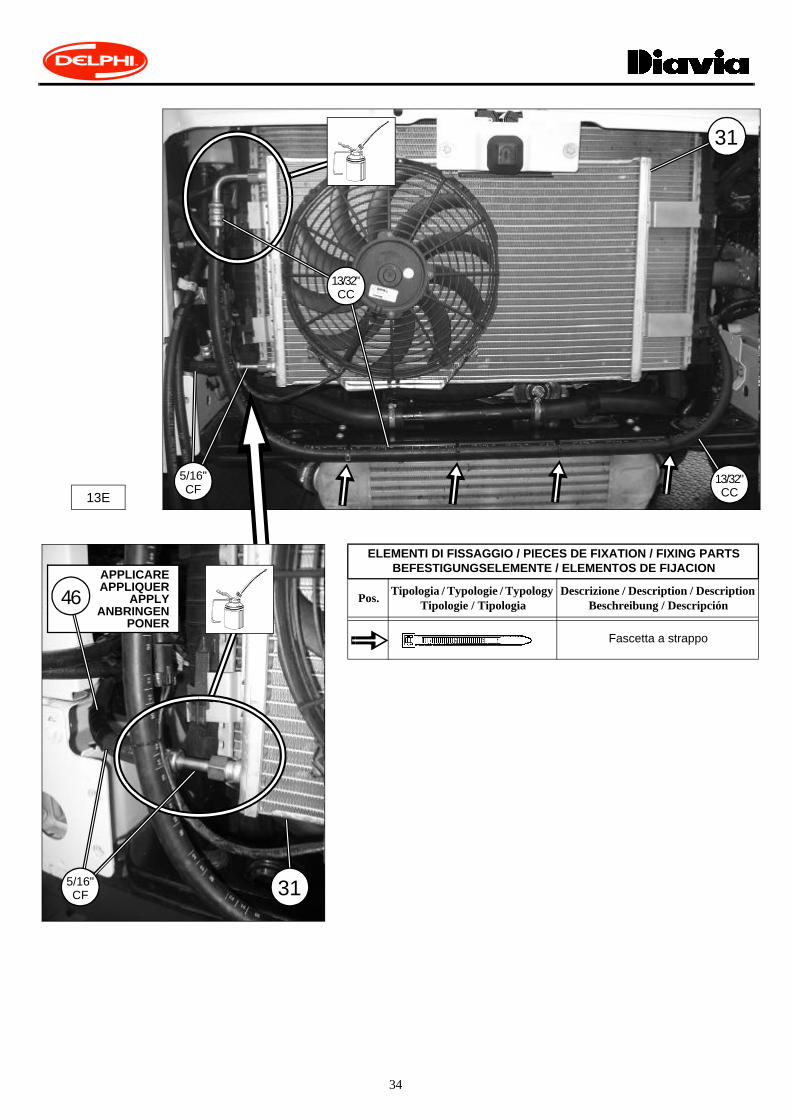
34
13E
ELEMENTI DI FISSAGGIO / PIECES DE FIXATION / FIXING PARTSBEFESTIGUNGSELEMENTE / ELEMENTOS DE FIJACION
Pos.Tipologia / Typologie / Typology
Tipologie / TipologiaDescrizione / Description / Description
Beschreibung / Descripción
Fascetta a strappo
31
13/32"CC
13/32"CC
5/16"CF
315/16"CF
APPLICAREAPPLIQUER
APPLYANBRINGEN
PONER
46

35
14E
15E
3
3
13/32"CC
13/32"CC
1/2"EC
1/2"EC
106
42
1/2"EC

36
ELEMENTI DI FISSAGGIO / PIECES DE FIXATIONFIXING PARTS / BEFESTIGUNGSELEMENTE
ELEMENTOS DE FIJACION
Pos.Tipologia / TypologieTypology / Tipologie
Tipologia
Descrizione / DescriptionDescription / Beschreibung
Descripción
106.1 φ6xφ18x2
106.2 M6
16E
47INSERIRE AD INCASTRO
INSERER PAR EMBOITEMENTTO INSERT TO JOINT
EINKLEMMENINSERIR A ENCASTRE
106.2
106
REINSERIRERÉINSÉRERSNAP BACK EINSETZEN
REINSERTAR
ORIGINALEORIGINAL
106.1
SMONTARE MOMENTANEAMENTEDEMONTER MOMENTANÉMENT
REMOVE MOMENTARILYMOMENTAN AUSBAUEN
DESMONTAR MOMENTÁNEAMENTE
106
22-2321
24106
22-2321
24106
37
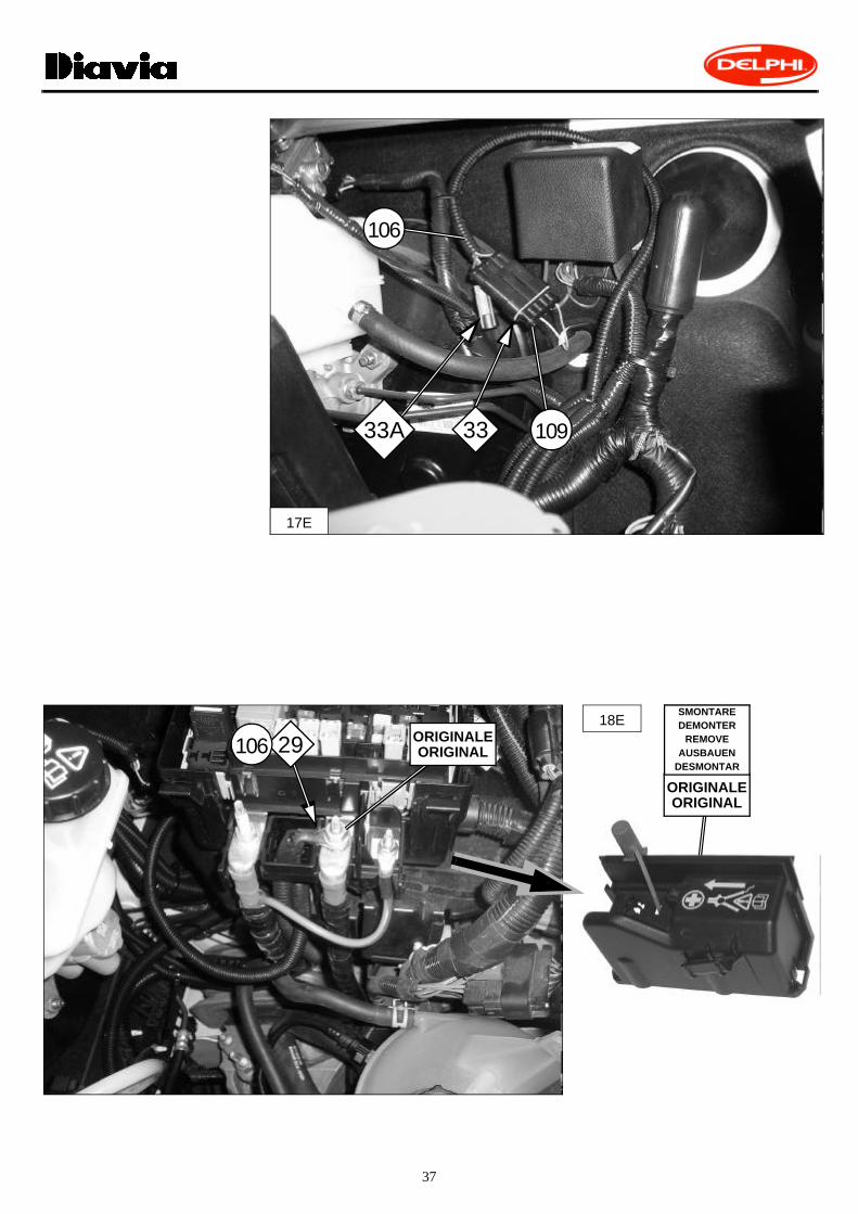
106
17E
33A 33 109
18EORIGINALEORIGINAL
ORIGINALEORIGINAL
SMONTAREDEMONTER
REMOVEAUSBAUEN
DESMONTAR
29106

38
19E
107
106
ORIGINALEORIGINAL
SMONTAREDEMONTER
REMOVEAUSBAUEN
DESMONTAR
27
20E
34
106
ORIGINALEORIGINAL
ORIGINALEORIGINAL
SMONTAREDEMONTER
REMOVEAUSBAUEN
DESMONTAR

39
106
21F
1910820
ORIGINALEORIGINAL
20 10619
40
22E
106
25
ELEMENTI DI FISSAGGIO / PIECES DE FIXATIONFIXING PARTS / BEFESTIGUNGSELEMENTE
ELEMENTOS DE FIJACION
Pos.Tipologia / TypologieTypology / Tipologie
Tipologia
Descrizione / DescriptionDescription / Beschreibung
Descripción
Fascettaa strappo 24E
53
ORIGINALEORIGINAL
30
32A32B
32
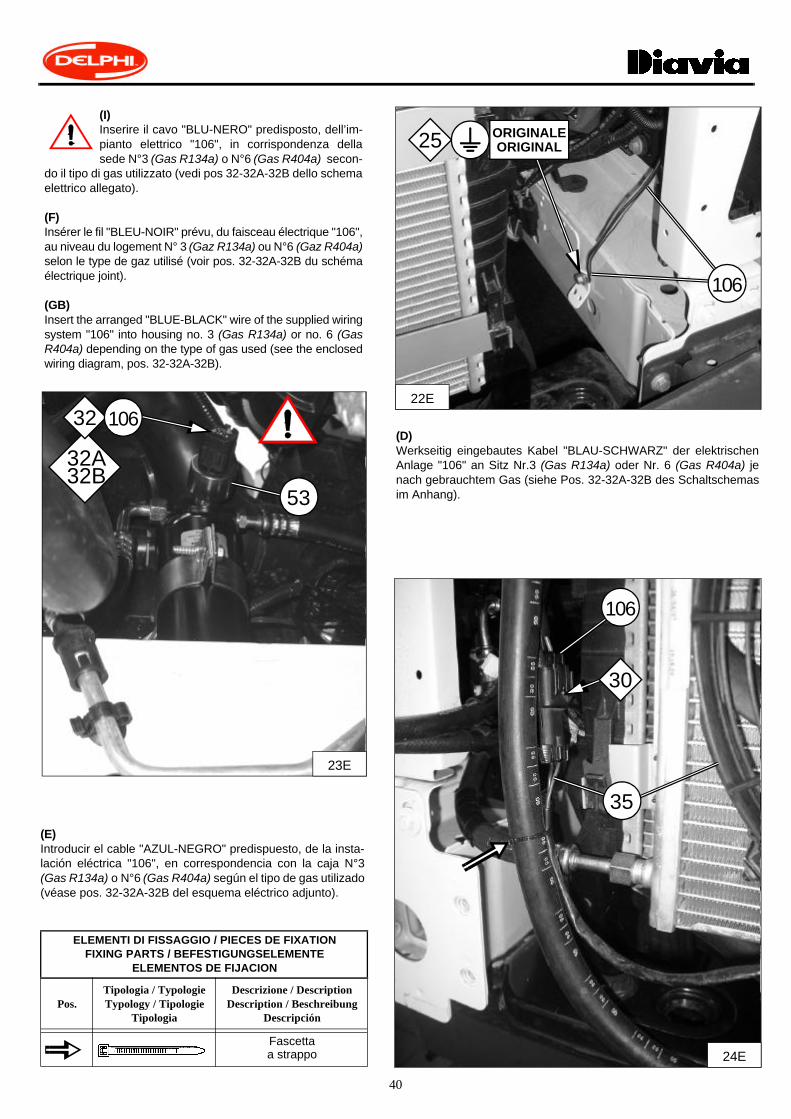
(I)Inserire il cavo "BLU-NERO" predisposto, dell’im-pianto elettrico "106", in corrispondenza dellasede N°3 (Gas R134a) o N°6 (Gas R404a) secon-
do il tipo di gas utilizzato (vedi pos 32-32A-32B dello schemaelettrico allegato).
(F)Insérer le fil "BLEU-NOIR" prévu, du faisceau électrique "106",au niveau du logement N° 3 (Gaz R134a) ou N°6 (Gaz R404a)selon le type de gaz utilisé (voir pos. 32-32A-32B du schémaélectrique joint).
(GB)Insert the arranged "BLUE-BLACK" wire of the supplied wiringsystem "106" into housing no. 3 (Gas R134a) or no. 6 (GasR404a) depending on the type of gas used (see the enclosedwiring diagram, pos. 32-32A-32B).
(D)Werkseitig eingebautes Kabel "BLAU-SCHWARZ" der elektrischenAnlage "106" an Sitz Nr.3 (Gas R134a) oder Nr. 6 (Gas R404a) jenach gebrauchtem Gas (siehe Pos. 32-32A-32B des Schaltschemasim Anhang).
(E)Introducir el cable "AZUL-NEGRO" predispuesto, de la insta-lación eléctrica "106", en correspondencia con la caja N°3(Gas R134a) o N°6 (Gas R404a) según el tipo de gas utilizado(véase pos. 32-32A-32B del esquema eléctrico adjunto).
35
106
23E
106
41
13
7
6
8
915
5 43
2
1
39
14A
14
0282471/1
35
40
38
10 11
36
37
12
M
19
2021
22
24
23
2526
29
27 28
42
31
25
E/V 31 E/V 31
X
1617
41
34B
34C
34A
34
AC
H O >902
2H O >100X
X
I II
33 33A
18
32B32A
32320282256/0
25
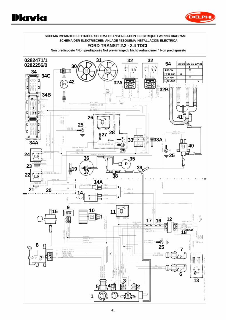
Non predisposto / Non predisposé / Not pre-arranged / Nicht vorhandener / Non predispuesto
30E/V 30
XA/C ONP>15 bar
54
SCHEMA IMPIANTO ELETTRICO / SCHEMA DE L'ISTALLATION ELECTRIQUE / WIRING DIAGRAMSCHEMA DER ELEKTRISCHEN ANLAGE / ESQUEMA INSTALLACION ELECTRICA
FORD TRANSIT 2.2 - 2.4 TDCI
P
42
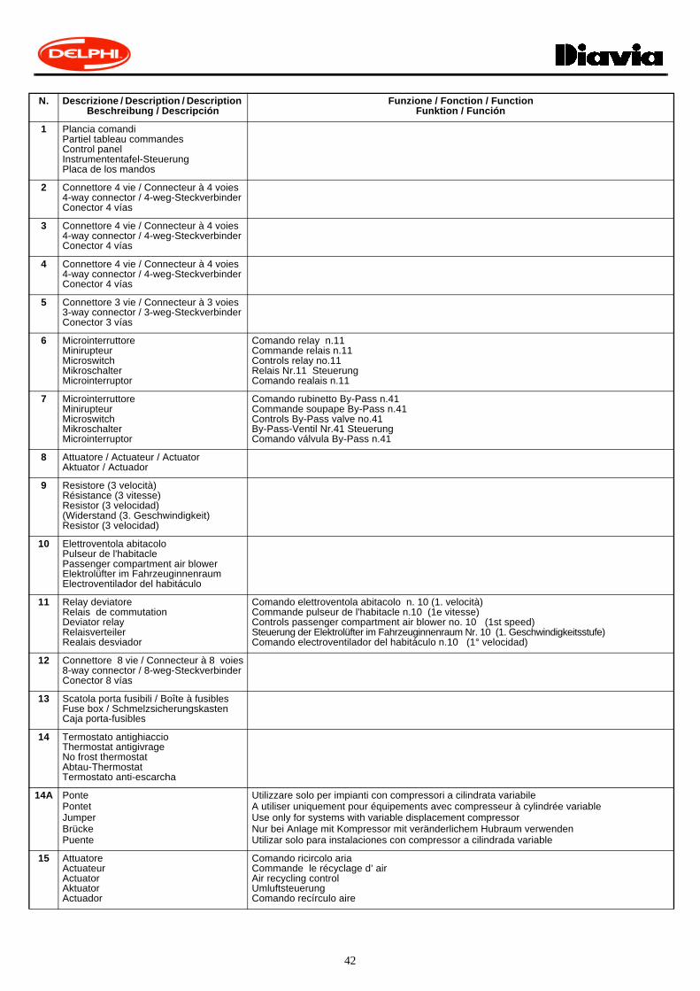
N. Descrizione / Description / Description Beschreibung / Descripción
Funzione / Fonction / FunctionFunktion / Función
1 Plancia comandiPartiel tableau commandesControl panelInstrumententafel-SteuerungPlaca de los mandos
2 Connettore 4 vie / Connecteur à 4 voies 4-way connector / 4-weg-SteckverbinderConector 4 vías
3 Connettore 4 vie / Connecteur à 4 voies 4-way connector / 4-weg-SteckverbinderConector 4 vías
4 Connettore 4 vie / Connecteur à 4 voies4-way connector / 4-weg-SteckverbinderConector 4 vías
5 Connettore 3 vie / Connecteur à 3 voies3-way connector / 3-weg-SteckverbinderConector 3 vías
6 MicrointerruttoreMinirupteurMicroswitchMikroschalterMicrointerruptor
Comando relay n.11Commande relais n.11Controls relay no.11Relais Nr.11 SteuerungComando realais n.11
7 MicrointerruttoreMinirupteurMicroswitchMikroschalterMicrointerruptor
Comando rubinetto By-Pass n.41Commande soupape By-Pass n.41Controls By-Pass valve no.41By-Pass-Ventil Nr.41 SteuerungComando válvula By-Pass n.41
8 Attuatore / Actuateur / ActuatorAktuator / Actuador
9 Resistore (3 velocità)Résistance (3 vitesse) Resistor (3 velocidad) (Widerstand (3. Geschwindigkeit)Resistor (3 velocidad)
10 Elettroventola abitacoloPulseur de l'habitaclePassenger compartment air blowerElektrolüfter im FahrzeuginnenraumElectroventilador del habitáculo
11 Relay deviatoreRelais de commutationDeviator relayRelaisverteilerRealais desviador
Comando elettroventola abitacolo n. 10 (1. velocità)Commande pulseur de l'habitacle n.10 (1e vitesse)Controls passenger compartment air blower no. 10 (1st speed)Steuerung der Elektrolüfter im Fahrzeuginnenraum Nr. 10 (1. Geschwindigkeitsstufe)Comando electroventilador del habitáculo n.10 (1° velocidad)
12 Connettore 8 vie / Connecteur à 8 voies8-way connector / 8-weg-SteckverbinderConector 8 vías
13 Scatola porta fusibili / Boîte à fusiblesFuse box / SchmelzsicherungskastenCaja porta-fusibles
14 Termostato antighiaccioThermostat antigivrageNo frost thermostat Abtau-ThermostatTermostato anti-escarcha
14A PontePontetJumperBrückePuente
Utilizzare solo per impianti con compressori a cilindrata variabileA utiliser uniquement pour équipements avec compresseur à cylindrée variableUse only for systems with variable displacement compressorNur bei Anlage mit Kompressor mit veränderlichem Hubraum verwendenUtilizar solo para instalaciones con compressor a cilindrada variable
15 AttuatoreActuateurActuatorAktuatorActuador
Comando ricircolo ariaCommande le récyclage d’ airAir recycling controlUmluftsteuerungComando recírculo aire

43
16 Giunzione RAYCHEM ROSSO Raccord RAYCHEM ROUGE RED RAYCHEM connector RAYCHEM Verbindung ROT Junta RAYCHEM ROJO
17 Giunzione RAYCHEM ROSSO Raccord RAYCHEM ROUGE RED RAYCHEM connector RAYCHEM Verbindung ROT Junta RAYCHEM ROJO
18 Giunzione RAYCHEM ROSSO Raccord RAYCHEM ROUGE RED RAYCHEM connector RAYCHEM Verbindung ROT Junta RAYCHEM ROJO
19 Connettore 1 viaConnecteur à 1 voie1-way connector1-Weg-SteckverbinderConector 1 vía
20 Connettore / Connecteur / Connector Steckverbinder / Conector
21 Fusibile 20A MaxiFusible 20A Maxi20A Maxi Fuse Schmelzsicherung 20A MaxiFusible 20A Maxi
22 Relay interruttore 70ARelais de coupure 70A70A Switch RelayRelais-Schalter 70ARelé interruptor 70A
Comando elettroventola n.30Commande l' électroventilateur n.30Fan no.30 controlElektrolüfter Nr.30-SteuerungComando electroventilador n.30
23 Fusibile 7.5A / Fusible 7.5A / 7.5A FuseSchmelzsicherung 7.5A / Fusible 7.5A
24 Micro relay interruttore 30AMicro Relais de coupure 30A30A microswitch RelayMikrorelais-Schalter 30AMicro realais interruptor 30A
Comando giunto elettromagnetico compressoreCommande l’embrayage électromagnetique du compresseurCompressor electromagnetic clutch controlSteuerung der elektromagnetischen Kupplung des KompressorsComando junta electromagnética compresor
25 Punto di massa originalePoint de masse d’origineOriginal ground pointOriginal-Massepunkt Punto de masa original
26 Scatola porta fusibili / Boîte à fusiblesFuse box / SchmelzsicherungskastenCaja porta-fusibles
27 Giunzione RAYCHEM ROSSO Raccord RAYCHEM ROUGE RED RAYCHEM connector RAYCHEM Verbindung ROT Junta RAYCHEM ROJO
Collegamento con +CHIAVE (+15)Connexion avec (+15)Connection with (+15)Anschluß mit (+15) Conexión con (+15)
28 Fusibile 60A Maxi Fusible 60A Maxi 60A Maxi Fuse Schmelzsicherung 60A Maxi Fusible 60A Maxi
29 Punto di derivazione batteria Point de dérivation batterieBattery connector pointBatterie-AbzweigungspunktPunto de conexiones de la batería
30 ElettroventolaElectroventilateurFanElektrolüfterElectroventilador
Raffreddamento radiatore e condensatoreRefroidissement radiateur et condenseurRadiator and condenser coolingKühler- und KondensatorkühlungEnfriamento radiator y condensador
31 ElettroventolaElectroventilateurFanElektrolüfterElectroventilador
Raffreddamento radiatore e condensatoreRefroidissement radiateur et condenseurRadiator and condenser coolingKühler- und KondensatorkühlungEnfriamento radiator y condensador

44
32 PressostatoPressostatPressure switchDruckwächterPresostato
Protezione impianto A/CProtection équipement A/CA/C system safety deviceKlimaanlagen-ÜberlastungsschutzProtección de la instalación A/C
32A Connettore 1 via Connecteur à 1 voie1-way connector 1-weg-SteckverbinderConector 1 vía
Collegamento per impianti con gas R134a Connexion pour équipement avec gaz R134a Connection for systems with R134a gas Anschluß für Kühlmittelanlagen R134aConexión para instalaciones con gas R134a
32B Connettore 1 viaConnecteur à 1 voie1-way connector1-weg-SteckverbinderConector 1 vía
Collegamento per impianti con gas R404a Connexion pour équipement avec gaz R404a Connection for systems with R404a gas Anschluß für Kühlmittelanlagen R404aConexión para instalaciones con gas R404a
33 Connettore 5 vieConnecteur à 5 voies5-way connector5-weg-SteckverbinderConector 5 vías
Non utilizzare A ne pas utiliserNot to be usedNicht benützenA no utilizar
33A Connettore 1 viaConnecteur à 1 voie1-way connector1-weg-SteckverbinderConector 1 vía
Non utilizzare A ne pas utiliserNot to be usedNicht benützenA no utilizar
34 Centralina IEDispositif de contrôle à injection électroniqueElectronic injection box unitElektronisches EinspritzgehäuseCentralita IE
FoMoCo 4CFF6C11-12A650-CF*VZ9KZ0A00DPN*
34A Connettore 32 vieConnecteur à 32 voies32-way connector32-weg-SteckverbinderConector 32 vías
34B Connettore 48 vieConnecteur à 48 voies48-way connector48-weg-SteckverbinderConector 48 vías
34C Connettore 32 vieConnecteur à 32 voies32-way connector32-weg-SteckverbinderConector 32 vías
35 Pompa depressione servo frenoPompe de dépression servofreinPower brake vacuum pumpUnterdruckpumpe der ServobremseBomba depresión servo freno
36 Servo frenoServofreinPower brakeServobremseServo freno
37 Valvola unidirezionaleSoupape unidirectionnelleUnidirectional valveSperrventilVàlvula unidireccional
38 Valvola unidirezionaleSoupape unidirectionnelleUnidirectional valveSperrventilVàlvula unidireccional

45
39 Raccordo depressioneRaccord de dépression Vacuum connector Unterdruck-VerbindungEmpalme depresión
40 Valvola solenoideÉlectrovanneSolenoid valveSolenoid-VentilVálvula solenoide
Comando rubinetto By-Pass n.41Commande soupape By-Pass n.41Controls By-Pass valve no.41By-Pass-Ventil Nr.41 SteuerungComando válvula By-Pass n.41
41 Rubinetto acquaSoupape de l’eauWater valveWasserventilVálvula agua
42 Giunto elettromagnetico compressoreEmbrayage électromagnetique du compresseurCompressor electromagnetic clutchElektromagnetische Kupplung des KompressorsJunta electromagnética del compresor
54 Logica funzionamento elettroventolaLogique fonctionnement électroventilateurElectric fan logicBetriebslogik der ElektrolüfterLogica funcionamiento electroventilador
ITALIANO FRANCAIS ENGLISH DEUTSCH ESPANOL
Arancio Orange Orange Orange Naranjado
Azzurro D’azur Light blue Hellbrau Azul
Bianco Blanc White Weiss Blanco
Blu Bleu Blue Blau Turqui
Giallo Jaune Yellow Gelb Amarillo
Grigio Gris Gray Grau Gris
Marrone Marron Brown Braun Marron
Nero Noir Black Schwarz Negro
Rosa Rose Pink Rosa Rosa
Rosso Rouge Red Rot Rojo
Verde Vert Green Grun Verde
Viola Violet Violet Violett Violado
(I)N.B.:Le parti in tratteggio rappresentano componentidell’impianto elettrico originale.
(F)N.B.:Les parties hachurées représentent des composan-ts du faisceau électrique d’origine.
(GB)N.B.:The dashed parts represent components of the ori-ginal electric system.
(D)N.B.:Die gestrichelten Teile stellen Bauteile der ur-spruenglichen Anlage dar.
(E)N.B.:Les partes discontinuas rapresentan componentsde la instalaciòn eléctrica original.
(I)DELPHI ITALIA mira ad un costante miglioramento dei propri prodotti. La Casa si riserva il diritto di apportare inqualunque momento e senza preavviso modifiche ai modelli e ai componenti descritti in questa pubblicazione perragioni di natura tecnica o commerciale. Per ulteriori informazioni rivolgersi al servizio assistenza DELPHI.
(F)DELPHI ITALIA vise à une amélioration constante des ces produits. La maison se réserve le droit d'apporter, à toutmoment et sans préavis, des modifications aux modèles et aux composants décrits dans cette publication pour desraisons d'ordre technique ou commerciale. Pour d'ultérieures informations s'adresser au service d'assistanceDELPHI.
(GB)DELPHI ITALIA focuses on constant upgrading of its products. The Manufacturer reserves the right to modify themodels and components described in the present publication at any time for technical or commercial reasons andwithout prior notice. For further information, contact DELPHI technical services.
(D)DELPHI ITALIA ist stets bestrebt die eigenen Produkte zu verbessern. Die Herstellerfirma behält sich das Rechtvor, aus technischen oder Verkaufsgründen, zu jeder Zeit und ohne vorherige Ankündigung, Abänderungen an denModellen und den in dieser Veröffentlichung beschriebenen Einbauteile vorzunehmen. Für weitere Informationenbitten wir Sie, sich an unseren DELPHI Kundendienst zu wenden.
(E)DELPHI ITALIA aspira a un constante mejoramiento de su producción. La Fábrica se reserva el derecho de aportaren cualquier momento y sin preaviso modificaciones a los modelos y los componentes descritos en esta publicaciónpor razones técnicas o comerciales. Para ulteriores informaciones dirigirse al servicio asistencia DELPHI.
MOD. SCHFO293 XI / ’07(2007)
VERKAUF UND SERVICESALE AND SERVICE
VENDITA E SERVIZIOVENTE ET SERVICE
Questa pubblicazione è stata curata da DELPHI ITALIA-Diavia
Stabilimento Molinella Via Nobili, 2 40062 Molinella (Bologna)-Italy Telefono (0039) 051.6906111 Fax (0039) 051.6906287
DELPHI ITALIA AUTOMOTIVE SYSTEMS S.r.l.
Ufficio Fitting Instructions - Stabilimento Molinella
This publication has been edited by DELPHI ITALIA-DiaviaFitting Instructions Office - Factory Molinella
Email: [email protected]