
Ford Everest
64
Everest Model Introduction Training For Approved Motor Body Repairers
Transcript of Ford Everest

EverestModel Introduction Training For Approved Motor Body Repairers
Copyright © 2009 Ford Motor Company of Southern Africa.
Powerful Stance with Eye-Catching Details
The new Everest has an unmistakably confident stance that communicates this vehicle is ready to go, whether it’s around town, on a great journey or to
even greater heights.
The bodywork of Everest’s sides is accentuated by bold wheel arches, which further communicate its stance, on-the-road handling character and off-road
capabilities. Visually, Everest is a vehicle of substance.
Everest’s profile also features a number of eye-catching details. These features make selective use of contrasting metal shades and chrome to
achieve an effect like that of accessories in a fashion ensemble.
This self-study programme highlights the design and function of new vehicle models, new automotive components or new technologies.
The self-study programme is not a repair manual!All values given are intended as a guideline only.
For maintenance and repair work, always refer to the current technical literature.
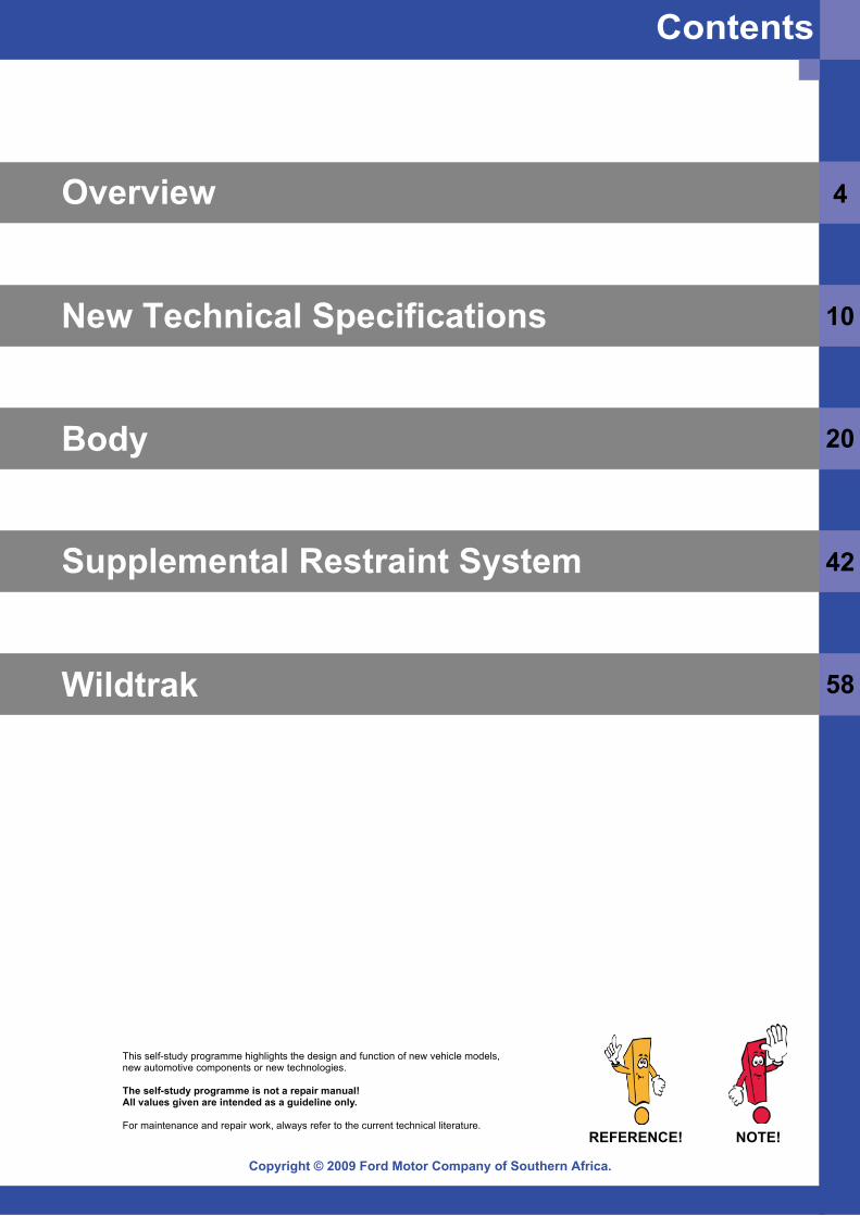
Contents
Copyright © 2009 Ford Motor Company of Southern Africa.
NOTE!REFERENCE!
Overview 4
New Technical Specifications 10
Body 20
Supplemental Restraint System 42
58Wildtrak
Copyright © 2009 Ford Motor Company of Southern Africa.4
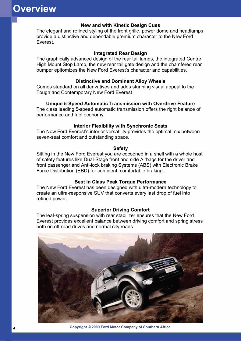
New and with Kinetic Design CuesThe elegant and refined styling of the front grille, power dome and headlamps provide a distinctive and dependable premium character to the New Ford Everest.
Integrated Rear Design The graphically advanced design of the rear tail lamps, the integrated Centre High Mount Stop Lamp, the new rear tail gate design and the chamfered rear bumper epitomizes the New Ford Everest’s character and capabilities.
Distinctive and Dominant Alloy Wheels Comes standard on all derivatives and adds stunning visual appeal to the Tough and Contemporary New Ford Everest
Unique 5-Speed Automatic Transmission with Overdrive Feature The class leading 5-speed automatic transmission offers the right balance of performance and fuel economy.
Interior Flexibility with Synchronic Seats The New Ford Everest’s interior versatility provides the optimal mix between seven-seat comfort and outstanding space.
Safety Sitting in the New Ford Everest you are cocooned in a shell with a whole host of safety features like Dual-Stage front and side Airbags for the driver and front passenger and Anti-lock braking Systems (ABS) with Electronic Brake Force Distribution (EBD) for confident, comfortable braking.
Best in Class Peak Torque Performance The New Ford Everest has been designed with ultra-modern technology to create an ultra-responsive SUV that converts every last drop of fuel into refined power.
Superior Driving Comfort The leaf-spring suspension with rear stabilizer ensures that the New Ford Everest provides excellent balance between driving comfort and spring stress both on off-road drives and normal city roads.
Overview

Copyright © 2009 Ford Motor Company of Southern Africa. 5
Key Features:
• 3.0 TDCi DuraTorq Engine • 4x4 • 5 Speed Automatic Transmission • ABS • Dual Front Airbags • Side Airbags
Key Features:
• 3.0 TDCi DuraTorq Engine • 4x4 • 5 Speed Manual Transmission • ABS • Dual Front Airbags • Side Airbags
Key Features:
• 3.0 TDCi DuraTorq Engine • 4x2 • 5 Speed Manual Transmission • ABS • Dual Front Airbags • Side Airbags
Models3.0TDCi 4x2 M/T XLT
3.0TDCi 4x4 M/T XLT
3.0TDCi 4x4 A/T LTD
Overview
Copyright © 2009 Ford Motor Company of Southern Africa.6
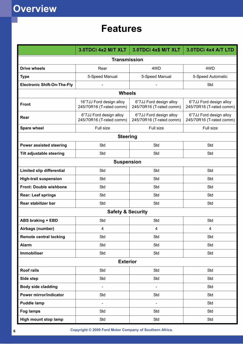
3.0TDCi 4x2 M/T XLT 3.0TDCi 4x$ M/T XLT 3.0TDCi 4x4 A/T LTD
TransmissionDrive wheels Rear 4WD 4WD
Type 5-Speed Manual 5-Speed Manual 5-Speed Automatic
Electronic Shift-On-The-Fly - - Std
Wheels
Front 16”7JJ Ford design alloy 245/70R16 (T-rated comm)
6”7JJ Ford design alloy 245/70R16 (T-rated comm)
6”7JJ Ford design alloy 245/70R16 (T-rated comm)
Rear 6”7JJ Ford design alloy 245/70R16 (T-rated comm)
6”7JJ Ford design alloy 245/70R16 (T-rated comm)
6”7JJ Ford design alloy 245/70R16 (T-rated comm)
Spare wheel Full size Full size Full size
SteeringPower assisted steering Std Std Std
Tilt adjustable steering Std Std Std
SuspensionLimited slip differential Std Std Std
High-trail suspension Std Std Std
Front: Double wishbone Std Std Std
Rear: Leaf springs Std Std Std
Rear stabilizer bar Std Std Std
Safety & SecurityABS braking + EBD Std Std Std
Airbags (number) 4 4 4
Remote central locking Std Std Std
Alarm Std Std Std
Immobiliser Std Std Std
ExteriorRoof rails Std Std Std
Side step Std Std Std
Body side cladding - - Std
Power mirror/indicator Std Std Std
Puddle lamp - - Std
Fog lamps Std Std Std
High mount stop lamp Std Std Std
Features
Overview

Copyright © 2009 Ford Motor Company of Southern Africa. 7
Power and Performance
Variable Geometry TurbochargerThe variable geometry turbocharger (VGT) virtually eliminates turbo lag and broadens the torque curve and provides great driving ease at low speeds, positive response and spirited acceleration, as well as greater engine power and torque in the New Ford Everest.
Peak Torque PerformanceThe 3-litre DuraTorq TDCi engine, delivers 115kW of power and 380Nm torque and provides the true 4x4 experience. The New Ford Everest adds quickness and agility to ultimate driving comfort.
3.0TDCI DuraTorq
Displacement cc 2953cc
Number of cylinders 4
Valve per cylinder 4
Bore and stroke 96x102 (mm)
Power (kW @ rpm) 115 @ 3200
Torque (Nm @ rpm) 380 @ 1800
Fuel system Stage II emissions
Turbocharger Std
Intercooler Std
Compression ratio 18.0:1
Engine Low SpeedVane Opening: SmallFlow Speed: High
Engine High SpeedVane Opening: LargeFlow Speed: Low
Overview
Copyright © 2009 Ford Motor Company of Southern Africa.8
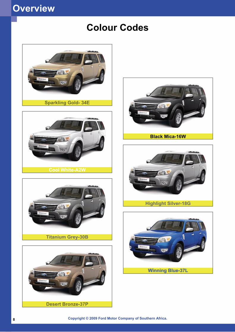
Colour Codes
Black Mica-16W
Highlight Silver-18G
Titanium Grey-30B
Winning Blue-37L
Cool White-A2W
Desert Bronze-37P
Sparkling Gold- 34E
Overview
Copyright © 2009 Ford Motor Company of Southern Africa. 9
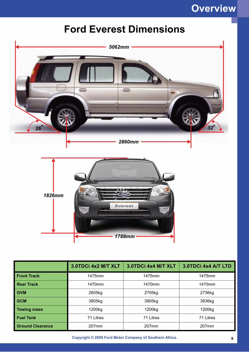
5062mm
2860mm
3226
3.0TDCi 4x2 M/T XLT 3.0TDCi 4x4 M/T XLT 3.0TDCi 4x4 A/T LTD
Front Track 1475mm 1475mm 1475mm
Rear Track 1470mm 1470mm 1470mm
GVM 2605kg 2705kg 2736kg
GCM 3805kg 3905kg 3936kg
Towing mass 1200kg 1200kg 1200kg
Fuel Tank 71 Litres 71 Litres 71 Litres
Ground Clearance 207mm 207mm 207mm
Ford Everest Dimensions
1788mm
1826mm
Overview
Copyright © 2009 Ford Motor Company of Southern Africa.10
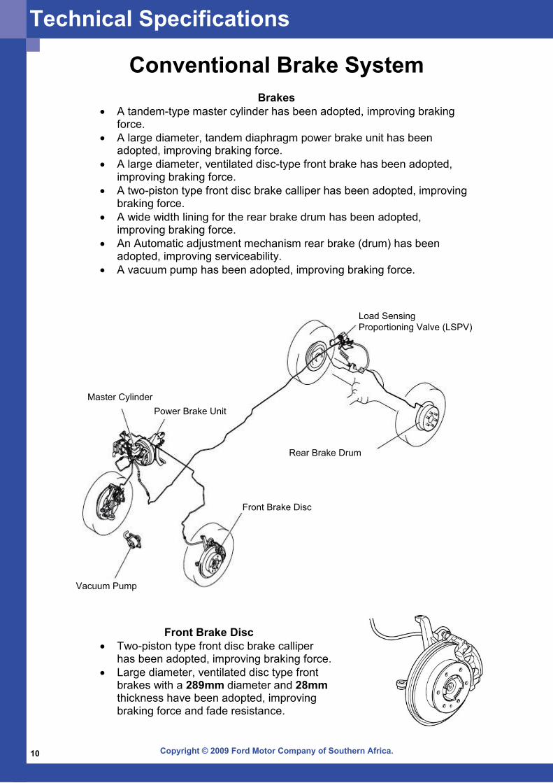
Conventional Brake SystemBrakes
• A tandem-type master cylinder has been adopted, improving braking force.
• A large diameter, tandem diaphragm power brake unit has been adopted, improving braking force.
• A large diameter, ventilated disc-type front brake has been adopted, improving braking force.
• A two-piston type front disc brake calliper has been adopted, improving braking force.
• A wide width lining for the rear brake drum has been adopted, improving braking force.
• An Automatic adjustment mechanism rear brake (drum) has been adopted, improving serviceability.
• A vacuum pump has been adopted, improving braking force.
Front Brake Disc
Rear Brake Drum
Vacuum Pump
Power Brake UnitMaster Cylinder
Front Brake Disc • Two-piston type front disc brake calliper
has been adopted, improving braking force. • Large diameter, ventilated disc type front
brakes with a 289mm diameter and 28mm thickness have been adopted, improving braking force and fade resistance.
Load SensingProportioning Valve (LSPV)
Technical Specifications
Copyright © 2009 Ford Motor Company of Southern Africa. 11
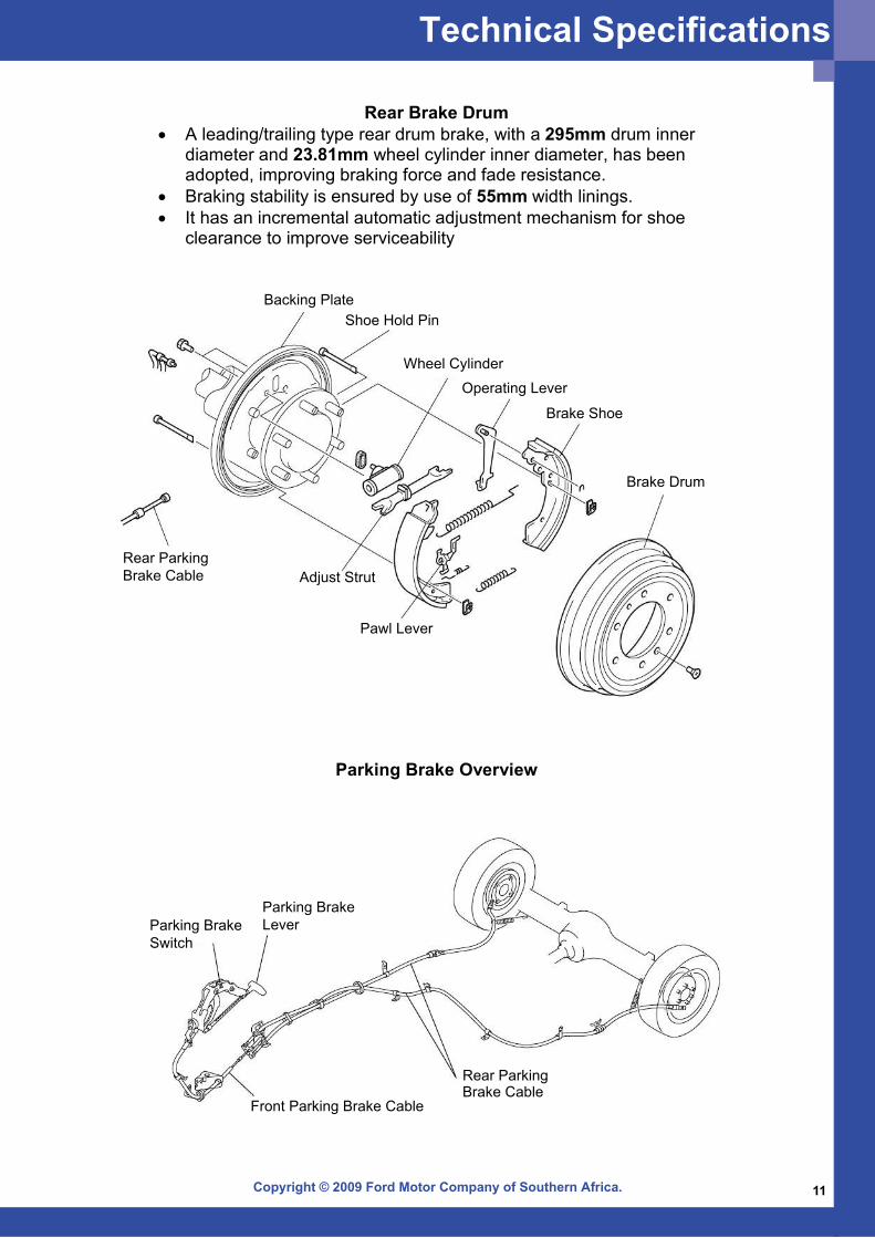
Rear Brake Drum • A leading/trailing type rear drum brake, with a 295mm drum inner
diameter and 23.81mm wheel cylinder inner diameter, has been adopted, improving braking force and fade resistance.
• Braking stability is ensured by use of 55mm width linings. • It has an incremental automatic adjustment mechanism for shoe
clearance to improve serviceability
Backing PlateShoe Hold Pin
Wheel Cylinder
Operating Lever
Brake Shoe
Brake Drum
Pawl Lever
Adjust StrutRear ParkingBrake Cable
Parking Brake Overview
Parking BrakeSwitch
Parking BrakeLever
Front Parking Brake Cable
Rear ParkingBrake Cable
Technical Specifications
Copyright © 2009 Ford Motor Company of Southern Africa.12
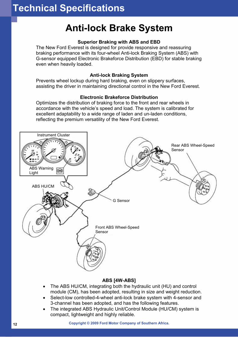
Anti-lock Brake SystemSuperior Braking with ABS and EBD
The New Ford Everest is designed for provide responsive and reassuring braking performance with its four-wheel Anti-lock Braking System (ABS) with G-sensor equipped Electronic Brakeforce Distribution (EBD) for stable braking even when heavily loaded.
Anti-lock Braking System Prevents wheel lockup during hard braking, even on slippery surfaces, assisting the driver in maintaining directional control in the New Ford Everest.
Electronic Brakeforce Distribution Optimizes the distribution of braking force to the front and rear wheels in accordance with the vehicle’s speed and load. The system is calibrated for excellent adaptability to a wide range of laden and un-laden conditions, reflecting the premium versatility of the New Ford Everest.
ABS [4W-ABS]• The ABS HU/CM, integrating both the hydraulic unit (HU) and control
module (CM), has been adopted, resulting in size and weight reduction.• Select-low controlled-4-wheel anti-lock brake system with 4-sensor and
3-channel has been adopted, and has the following features. • The integrated ABS Hydraulic Unit/Control Module (HU/CM) system is
compact, lightweight and highly reliable.
Rear ABS Wheel-SpeedSensor
G Sensor
Front ABS Wheel-SpeedSensor
ABS HU/CM
ABS WarningLight
Instrument Cluster
Technical Specifications
Copyright © 2009 Ford Motor Company of Southern Africa. 13
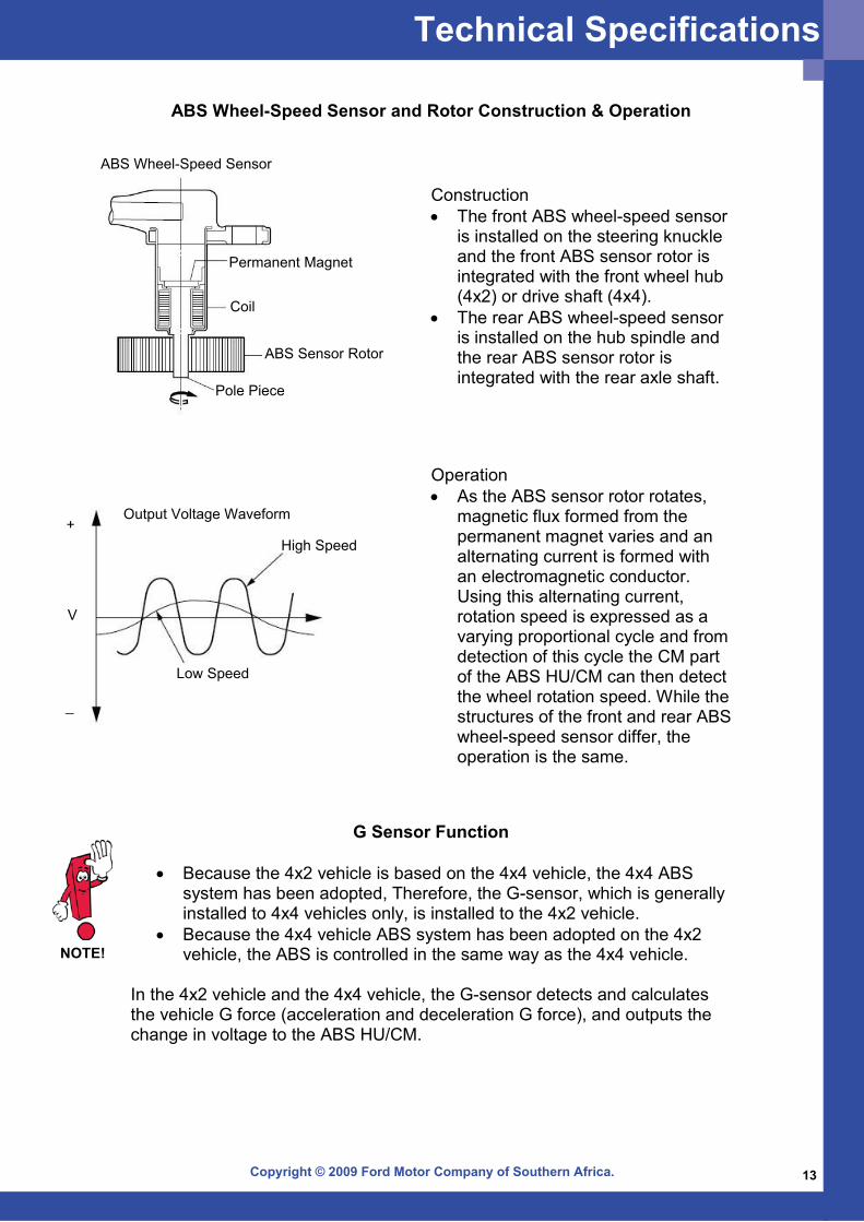
Operation • As the ABS sensor rotor rotates,
magnetic flux formed from the permanent magnet varies and an alternating current is formed with an electromagnetic conductor. Using this alternating current, rotation speed is expressed as a varying proportional cycle and from detection of this cycle the CM part of the ABS HU/CM can then detect the wheel rotation speed. While the structures of the front and rear ABS wheel-speed sensor differ, the operation is the same.
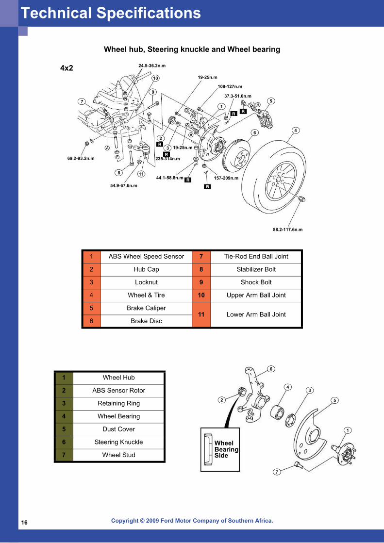
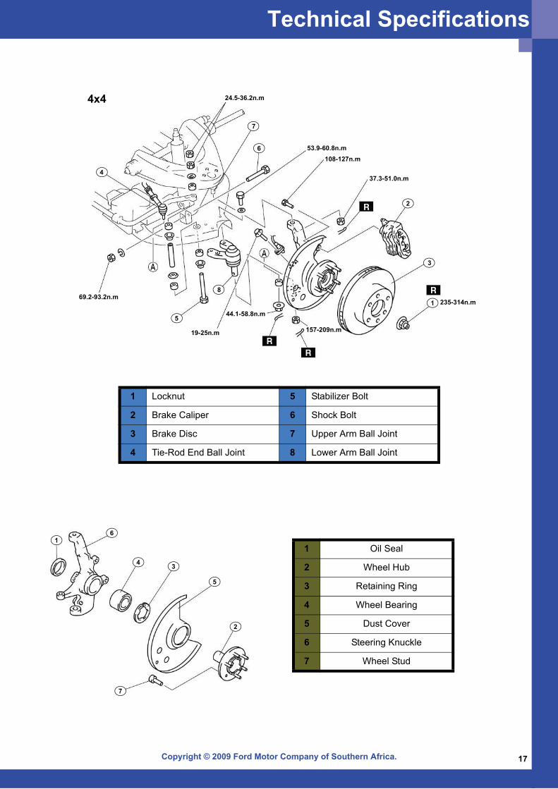
Construction • The front ABS wheel-speed sensor
is installed on the steering knuckle and the front ABS sensor rotor is integrated with the front wheel hub (4x2) or drive shaft (4x4).
• The rear ABS wheel-speed sensor is installed on the hub spindle and the rear ABS sensor rotor is integrated with the rear axle shaft.
ABS Wheel-Speed Sensor and Rotor Construction & Operation
G Sensor Function
• Because the 4x2 vehicle is based on the 4x4 vehicle, the 4x4 ABS system has been adopted, Therefore, the G-sensor, which is generally installed to 4x4 vehicles only, is installed to the 4x2 vehicle.
• Because the 4x4 vehicle ABS system has been adopted on the 4x2 vehicle, the ABS is controlled in the same way as the 4x4 vehicle.
In the 4x2 vehicle and the 4x4 vehicle, the G-sensor detects and calculates the vehicle G force (acceleration and deceleration G force), and outputs the change in voltage to the ABS HU/CM.
NOTE!
ABS Wheel-Speed Sensor
Permanent Magnet
Coil
ABS Sensor Rotor
Pole Piece
Output Voltage Waveform
High Speed
Low Speed
+
_
V
Technical Specifications
Copyright © 2009 Ford Motor Company of Southern Africa.14
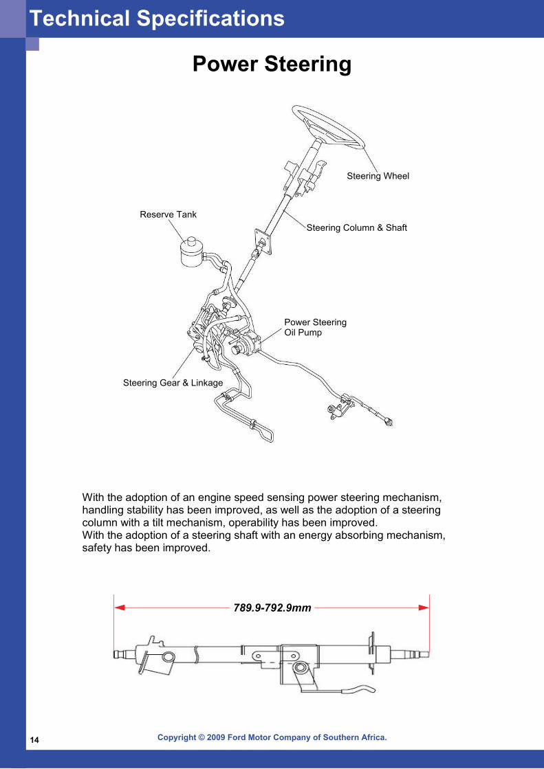
Power Steering
With the adoption of an engine speed sensing power steering mechanism, handling stability has been improved, as well as the adoption of a steering column with a tilt mechanism, operability has been improved. With the adoption of a steering shaft with an energy absorbing mechanism, safety has been improved.
789.9-792.9mm
Steering Wheel
Steering Column & Shaft
Power SteeringOil Pump
Steering Gear & Linkage
Reserve Tank
Technical Specifications
Copyright © 2009 Ford Motor Company of Southern Africa. 15
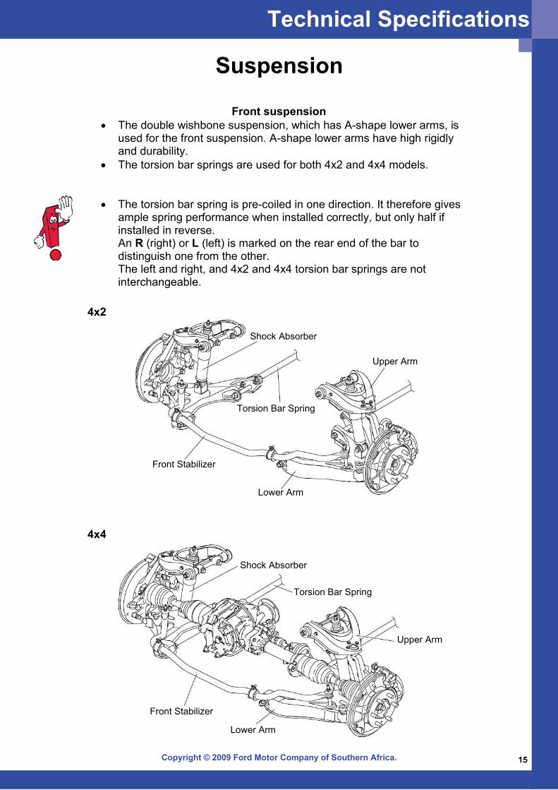
Suspension
Front suspension • The double wishbone suspension, which has A-shape lower arms, is
used for the front suspension. A-shape lower arms have high rigidly and durability.
• The torsion bar springs are used for both 4x2 and 4x4 models.
• The torsion bar spring is pre-coiled in one direction. It therefore gives ample spring performance when installed correctly, but only half if installed in reverse. An R (right) or L (left) is marked on the rear end of the bar to distinguish one from the other. The left and right, and 4x2 and 4x4 torsion bar springs are not interchangeable.
Torsion Bar Spring
Shock Absorber
Upper Arm
Lower Arm
Front Stabilizer
Shock Absorber
Torsion Bar Spring
Upper Arm
Lower Arm
Front Stabilizer
4x2
4x4
Technical Specifications
Copyright © 2009 Ford Motor Company of Southern Africa.16
Wheel hub, Steering knuckle and Wheel bearing
24.5-36.2n.m
19-25n.m
108-127n.m
37.3-51.0n.m
69.2-93.2n.m
54.9-67.6n.m
44.1-58.8n.m
235-314n.m
19-25n.m
157-209n.m
88.2-117.6n.m
10
9
15
6 4
3
2
11
7
8
1 ABS Wheel Speed Sensor 7 Tie-Rod End Ball Joint
2 Hub Cap 8 Stabilizer Bolt
3 Locknut 9 Shock Bolt
4 Wheel & Tire 10 Upper Arm Ball Joint
5 Brake Caliper11 Lower Arm Ball Joint
6 Brake Disc
1 Wheel Hub
2 ABS Sensor Rotor
3 Retaining Ring
4 Wheel Bearing
5 Dust Cover
6 Steering Knuckle
7 Wheel Stud
1
2
34
5
6
7
WheelBearingSide
4x2
Technical Specifications
Copyright © 2009 Ford Motor Company of Southern Africa. 17
4x4
1
2
3
4
5
6
7
8
24.5-36.2n.m
53.9-60.8n.m108-127n.m
37.3-51.0n.m
235-314n.m
157-209n.m
44.1-58.8n.m
19-25n.m
69.2-93.2n.m
1 Locknut 5 Stabilizer Bolt
2 Brake Caliper 6 Shock Bolt
3 Brake Disc 7 Upper Arm Ball Joint
4 Tie-Rod End Ball Joint 8 Lower Arm Ball Joint
1
2
34
5
6
7
1 Oil Seal
2 Wheel Hub
3 Retaining Ring
4 Wheel Bearing
5 Dust Cover
6 Steering Knuckle
7 Wheel Stud
Technical Specifications
Copyright © 2009 Ford Motor Company of Southern Africa.18
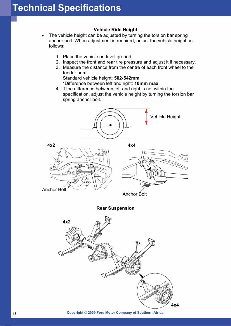
Vehicle Ride Height• The vehicle height can be adjusted by turning the torsion bar spring
anchor bolt. When adjustment is required, adjust the vehicle height as follows:
1. Place the vehicle on level ground. 2. Inspect the front and rear tire pressure and adjust it if necessary.3. Measure the distance from the centre of each front wheel to the
fender brim. Standard vehicle height: 502-542mm *Difference between left and right: 10mm max
4. If the difference between left and right is not within the specification, adjust the vehicle height by turning the torsion bar spring anchor bolt.
Anchor BoltAnchor Bolt
4x44x2
Vehicle Height
Rear Suspension
4x2
4x4
Technical Specifications
Copyright © 2009 Ford Motor Company of Southern Africa. 19
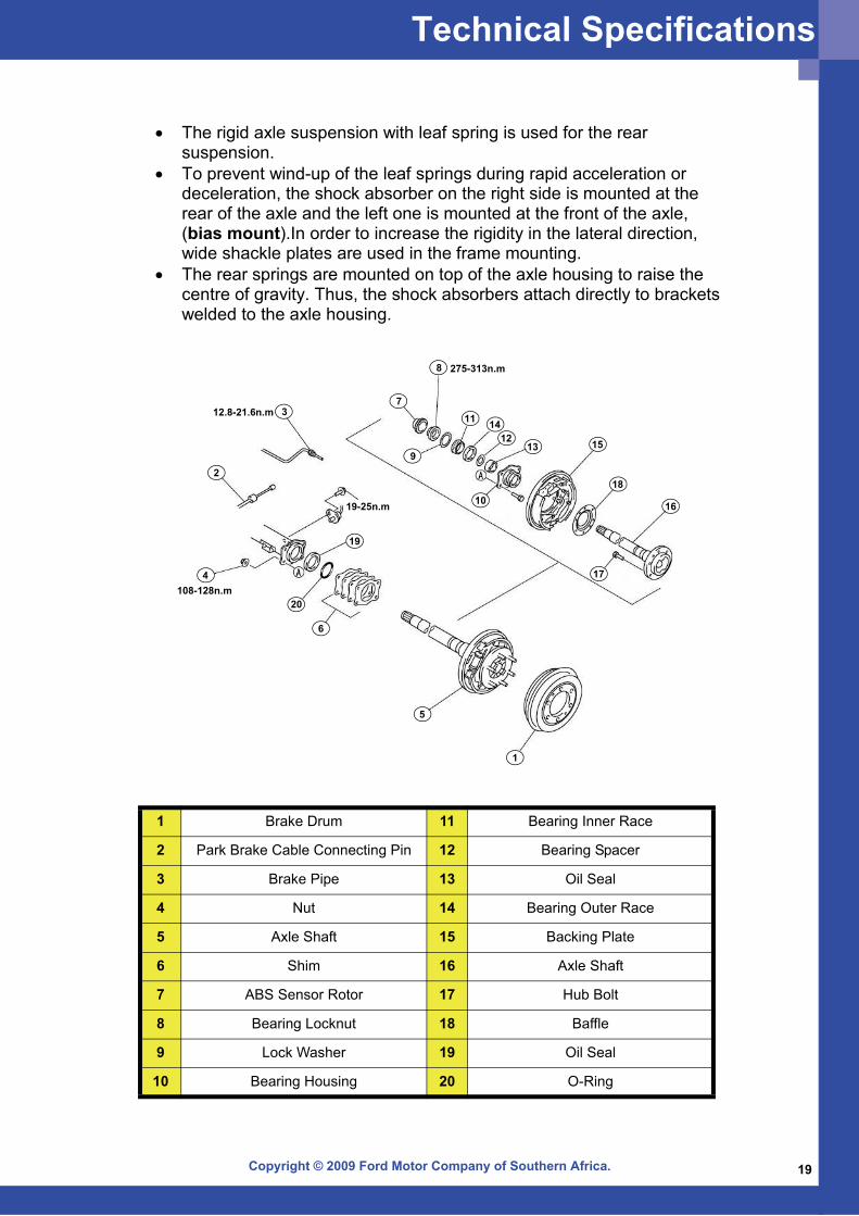
1 Brake Drum 11 Bearing Inner Race
2 Park Brake Cable Connecting Pin 12 Bearing Spacer
3 Brake Pipe 13 Oil Seal
4 Nut 14 Bearing Outer Race
5 Axle Shaft 15 Backing Plate
6 Shim 16 Axle Shaft
7 ABS Sensor Rotor 17 Hub Bolt
8 Bearing Locknut 18 Baffle
9 Lock Washer 19 Oil Seal
10 Bearing Housing 20 O-Ring
• The rigid axle suspension with leaf spring is used for the rear suspension.
• To prevent wind-up of the leaf springs during rapid acceleration or deceleration, the shock absorber on the right side is mounted at the rear of the axle and the left one is mounted at the front of the axle, (bias mount).In order to increase the rigidity in the lateral direction, wide shackle plates are used in the frame mounting.
• The rear springs are mounted on top of the axle housing to raise the centre of gravity. Thus, the shock absorbers attach directly to brackets welded to the axle housing.
Technical Specifications
1
2
3
4
5
6
7
8 275-313n.m
12.8-21.6n.m
19-25n.m
108-128n.m
9
10
11
1213
14
15
16
17
18
19
20
Copyright © 2009 Ford Motor Company of Southern Africa.20
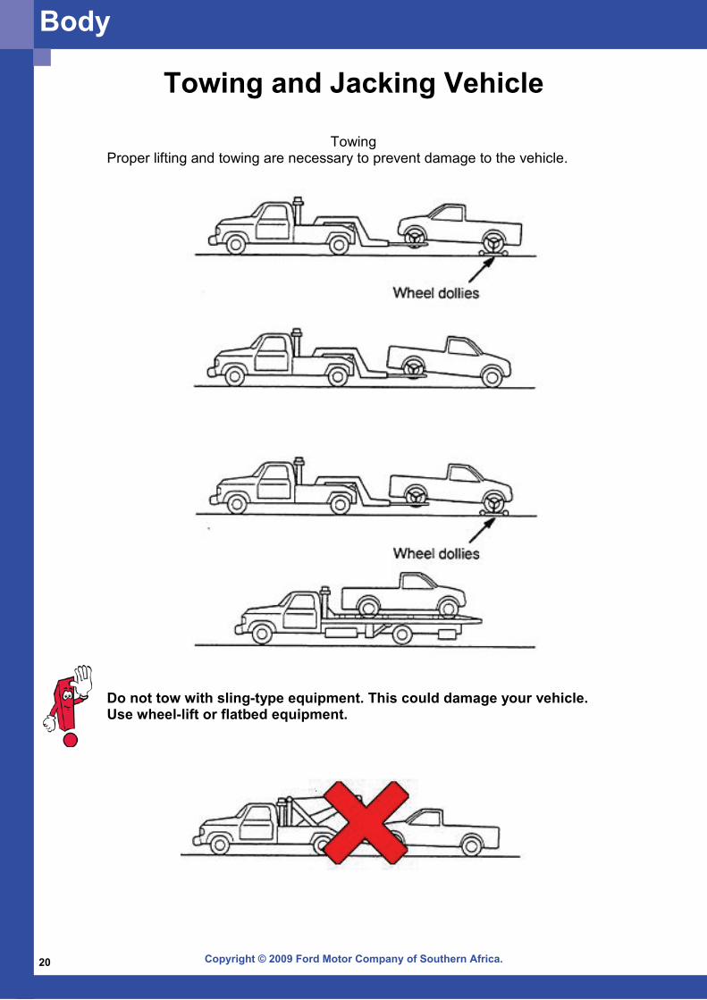
Towing and Jacking Vehicle
Towing Proper lifting and towing are necessary to prevent damage to the vehicle.
Do not tow with sling-type equipment. This could damage your vehicle. Use wheel-lift or flatbed equipment.
Body
Copyright © 2009 Ford Motor Company of Southern Africa. 21
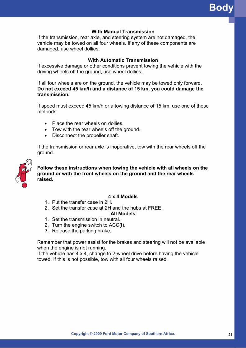
Follow these instructions when towing the vehicle with all wheels on the ground or with the front wheels on the ground and the rear wheels raised.
4 x 4 Models1. Put the transfer case in 2H. 2. Set the transfer case at 2H and the hubs at FREE.
All Models 1. Set the transmission in neutral. 2. Turn the engine switch to ACC(I). 3. Release the parking brake.
Remember that power assist for the brakes and steering will not be available when the engine is not running. If the vehicle has 4 x 4, change to 2-wheel drive before having the vehicle towed. If this is not possible, tow with all four wheels raised.
With Manual TransmissionIf the transmission, rear axle, and steering system are not damaged, the vehicle may be towed on all four wheels. If any of these components are damaged, use wheel dollies.
With Automatic Transmission If excessive damage or other conditions prevent towing the vehicle with the driving wheels off the ground, use wheel dollies. If all four wheels are on the ground, the vehicle may be towed only forward. Do not exceed 45 km/h and a distance of 15 km, you could damage the transmission. If speed must exceed 45 km/h or a towing distance of 15 km, use one of these methods:
• Place the rear wheels on dollies. • Tow with the rear wheels off the ground. • Disconnect the propeller shaft.
If the transmission or rear axle is inoperative, tow with the rear wheels off the ground.
Body
Copyright © 2009 Ford Motor Company of Southern Africa.22
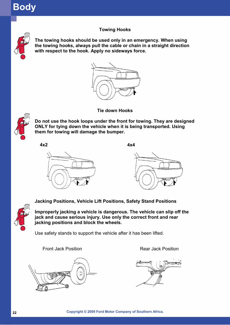
Towing Hooks
The towing hooks should be used only in an emergency. When using the towing hooks, always pull the cable or chain in a straight direction with respect to the hook. Apply no sideways force.
Tie down Hooks
Do not use the hook loops under the front for towing. They are designed ONLY for tying down the vehicle when it is being transported. Using them for towing will damage the bumper.
4x44x2
Jacking Positions, Vehicle Lift Positions, Safety Stand Positions Improperly jacking a vehicle is dangerous. The vehicle can slip off the jack and cause serious injury. Use only the correct front and rear jacking positions and block the wheels. Use safety stands to support the vehicle after it has been lifted.
Front Jack Position Rear Jack Position
Body

Copyright © 2009 Ford Motor Company of Southern Africa. 23
Front Lift Post Rear Lift Post
Front Safety Stands Rear Safety Stands
Body
Copyright © 2009 Ford Motor Company of Southern Africa.24
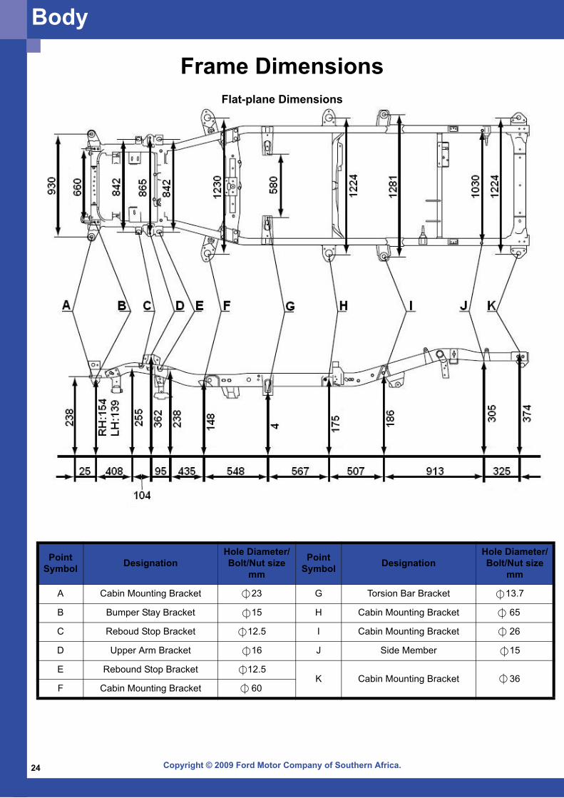
Frame DimensionsFlat-plane Dimensions
Point Symbol Designation
Hole Diameter/Bolt/Nut size
mm
Point Symbol Designation
Hole Diameter/Bolt/Nut size
mm
A Cabin Mounting Bracket 23 G Torsion Bar Bracket 13.7
B Bumper Stay Bracket 15 H Cabin Mounting Bracket 65
C Reboud Stop Bracket 12.5 I Cabin Mounting Bracket 26
D Upper Arm Bracket 16 J Side Member 15
E Rebound Stop Bracket 12.5K Cabin Mounting Bracket 36
F Cabin Mounting Bracket 60
Body
Copyright © 2009 Ford Motor Company of Southern Africa. 25
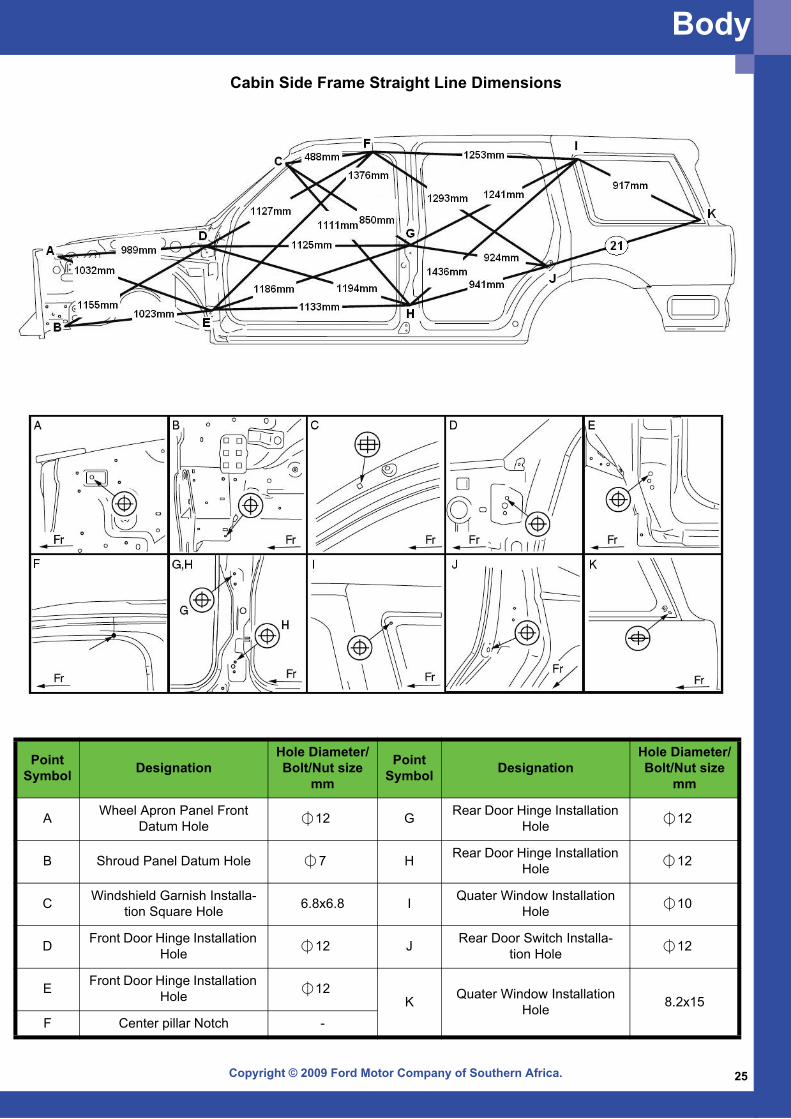
Cabin Side Frame Straight Line Dimensions
Point Symbol Designation
Hole Diameter/Bolt/Nut size
mm
Point Symbol Designation
Hole Diameter/Bolt/Nut size
mm
A Wheel Apron Panel Front Datum Hole 12 G Rear Door Hinge Installation
Hole 12
B Shroud Panel Datum Hole 7 H Rear Door Hinge Installation Hole 12
C Windshield Garnish Installa-tion Square Hole 6.8x6.8 I Quater Window Installation
Hole 10
D Front Door Hinge Installation Hole 12 J Rear Door Switch Installa-
tion Hole 12
E Front Door Hinge Installation Hole 12
K Quater Window Installation Hole 8.2x15
F Center pillar Notch -
Body
Copyright © 2009 Ford Motor Company of Southern Africa.26
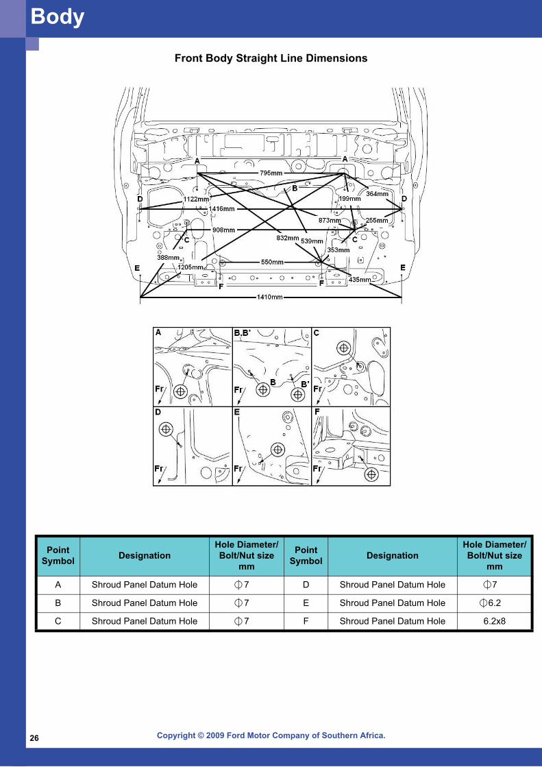
Front Body Straight Line Dimensions
Point Symbol Designation
Hole Diameter/Bolt/Nut size
mm
Point Symbol Designation
Hole Diameter/Bolt/Nut size
mm
A Shroud Panel Datum Hole 7 D Shroud Panel Datum Hole 7
B Shroud Panel Datum Hole 7 E Shroud Panel Datum Hole 6.2
C Shroud Panel Datum Hole 7 F Shroud Panel Datum Hole 6.2x8
Body
Copyright © 2009 Ford Motor Company of Southern Africa. 27
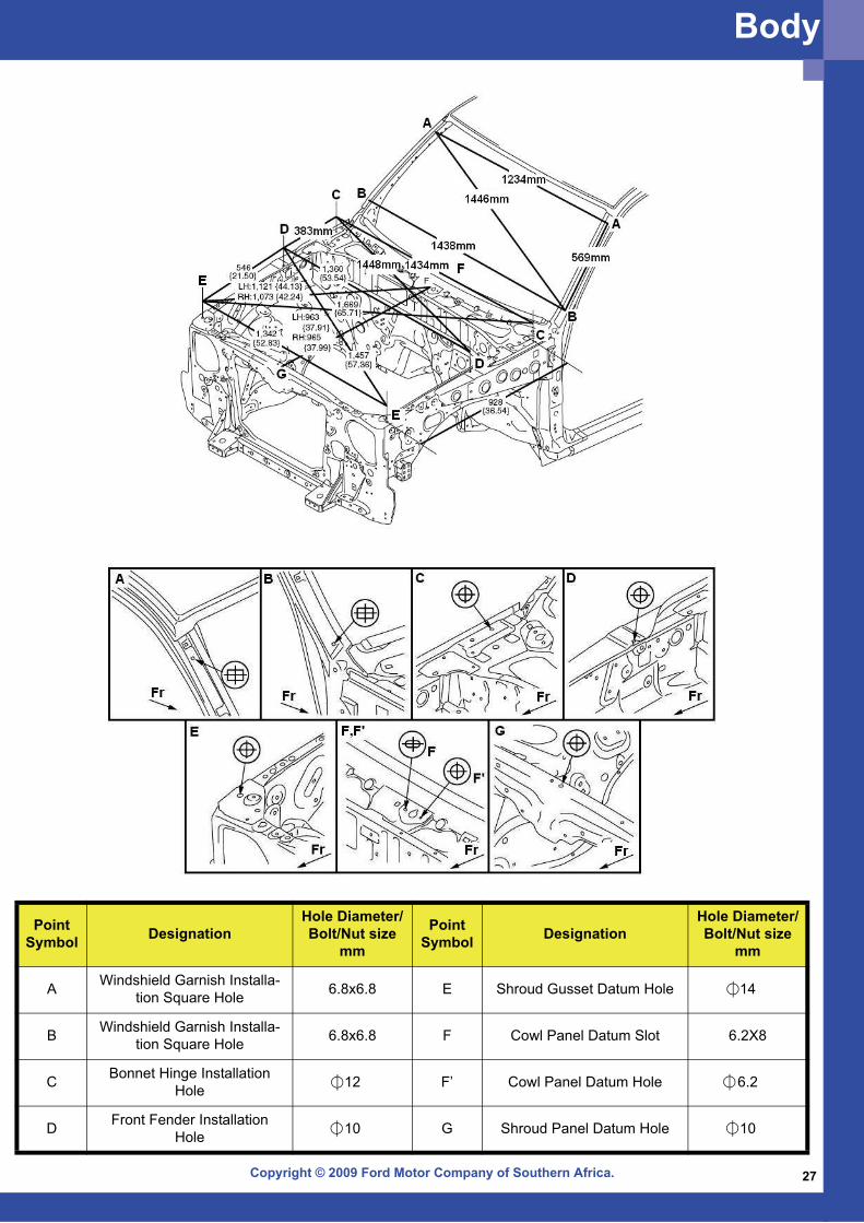
Point Symbol Designation
Hole Diameter/Bolt/Nut size
mm
Point Symbol Designation
Hole Diameter/Bolt/Nut size
mm
A Windshield Garnish Installa-tion Square Hole 6.8x6.8 E Shroud Gusset Datum Hole 14
B Windshield Garnish Installa-tion Square Hole 6.8x6.8 F Cowl Panel Datum Slot 6.2X8
C Bonnet Hinge Installation Hole 12 F’ Cowl Panel Datum Hole 6.2
D Front Fender Installation Hole 10 G Shroud Panel Datum Hole 10
Body
Copyright © 2009 Ford Motor Company of Southern Africa.28
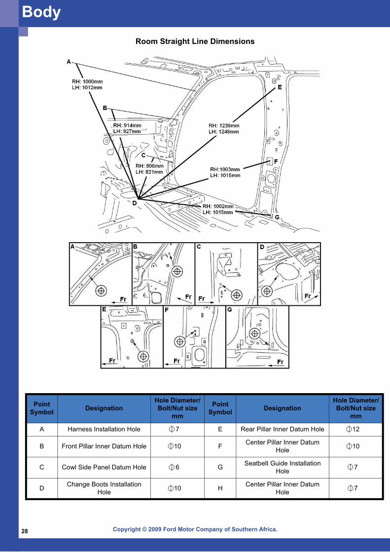
Point Symbol Designation
Hole Diameter/Bolt/Nut size
mm
Point Symbol Designation
Hole Diameter/Bolt/Nut size
mm
A Harness Installation Hole 7 E Rear Pillar Inner Datum Hole 12
B Front Pillar Inner Datum Hole 10 F Center Pillar Inner Datum Hole 10
C Cowl Side Panel Datum Hole 6 G Seatbelt Guide Installation Hole 7
D Change Boots Installation Hole 10 H Center Pillar Inner Datum
Hole 7
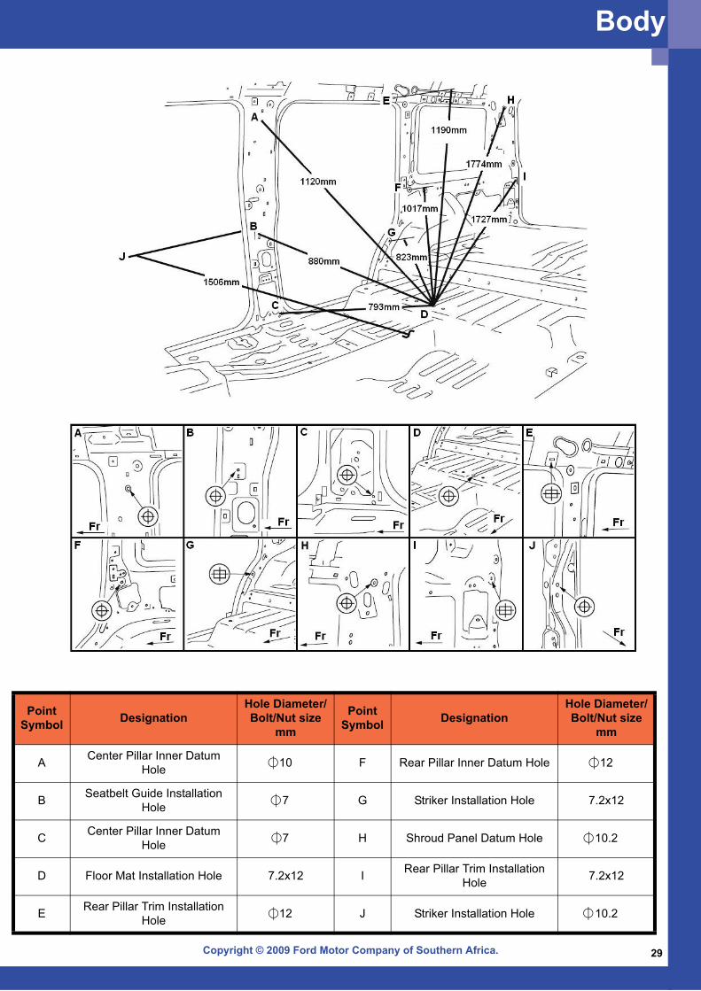
Room Straight Line Dimensions
Body
Copyright © 2009 Ford Motor Company of Southern Africa. 29
Point Symbol Designation
Hole Diameter/Bolt/Nut size
mm
Point Symbol Designation
Hole Diameter/Bolt/Nut size
mm
A Center Pillar Inner Datum Hole 10 F Rear Pillar Inner Datum Hole 12
B Seatbelt Guide Installation Hole 7 G Striker Installation Hole 7.2x12
C Center Pillar Inner Datum Hole 7 H Shroud Panel Datum Hole 10.2
D Floor Mat Installation Hole 7.2x12 I Rear Pillar Trim Installation Hole 7.2x12
E Rear Pillar Trim Installation Hole 12 J Striker Installation Hole 10.2
Body
Copyright © 2009 Ford Motor Company of Southern Africa.30
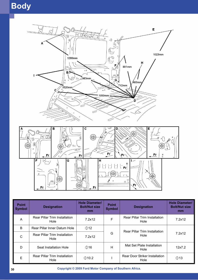
Point Symbol Designation
Hole Diameter/Bolt/Nut size
mm
Point Symbol Designation
Hole Diameter/Bolt/Nut size
mm
A Rear Pillar Trim Installation Hole 7.2x12 F Rear Pillar Trim Installation
Hole 7.2x12
B Rear Pillar Inner Datum Hole 12G Rear Pillar Trim Installation
Hole 7.2x12C Rear Pillar Trim Installation
Hole 7.2x12
D Seat Installation Hole 16 H Mat Set Plate Installation Hole 12x7.2
E Rear Pillar Trim Installation Hole 10.2 I Rear Door Striker Installation
Hole 13
Body
Copyright © 2009 Ford Motor Company of Southern Africa. 31
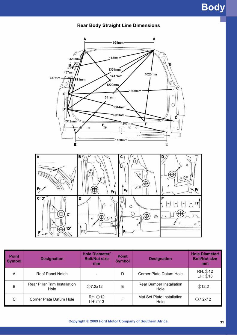
Rear Body Straight Line Dimensions
Point Symbol Designation
Hole Diameter/Bolt/Nut size
mm
Point Symbol Designation
Hole Diameter/Bolt/Nut size
mm
A Roof Panel Notch - D Corner Plate Datum Hole RH: 12LH: 13
B Rear Pillar Trim Installation Hole 7.2x12 E Rear Bumper Installation
Hole 12.2
C Corner Plate Datum Hole RH: 12LH: 13 F Mat Set Plate Installation
Hole 7.2x12
Body
Copyright © 2009 Ford Motor Company of Southern Africa.32
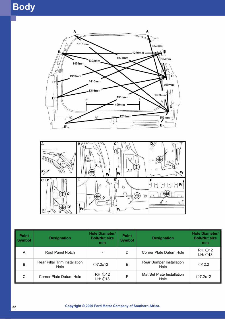
Point Symbol Designation
Hole Diameter/Bolt/Nut size
mm
Point Symbol Designation
Hole Diameter/Bolt/Nut size
mm
A Roof Panel Notch - D Corner Plate Datum Hole RH: 12LH: 13
B Rear Pillar Trim Installation Hole 7.2x12 E Rear Bumper Installation
Hole 12.2
C Corner Plate Datum Hole RH: 12LH: 13 F Mat Set Plate Installation
Hole 7.2x12
Body
Copyright © 2009 Ford Motor Company of Southern Africa. 33
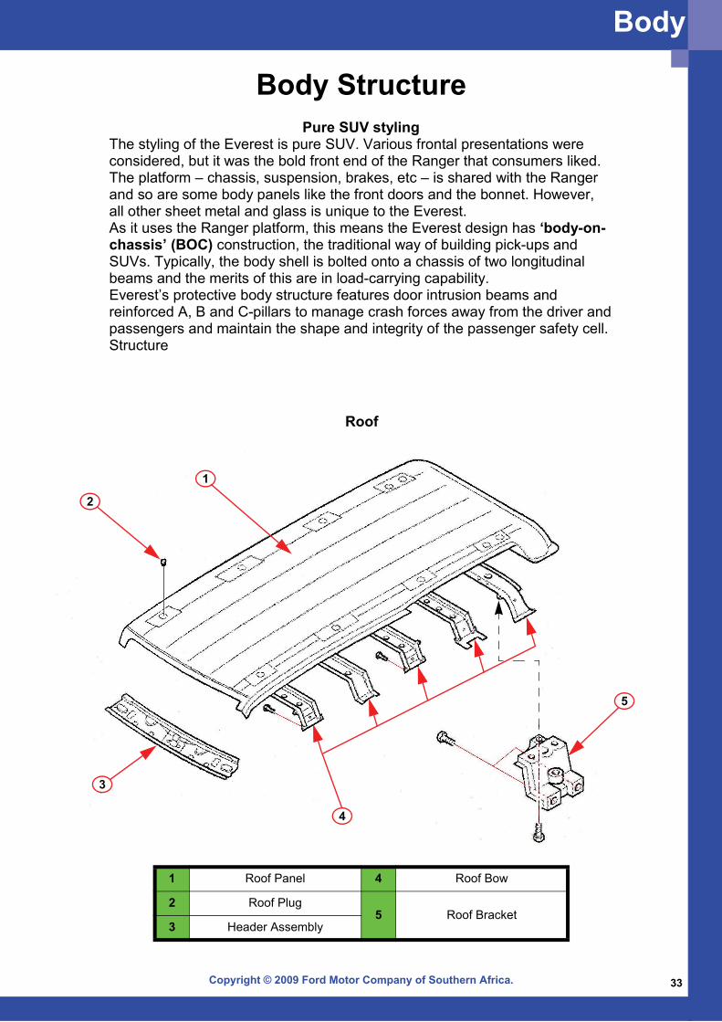
Roof
1
2
3
4
5
1 Roof Panel 4 Roof Bow
2 Roof Plug5 Roof Bracket
3 Header Assembly
Body StructurePure SUV styling
The styling of the Everest is pure SUV. Various frontal presentations were considered, but it was the bold front end of the Ranger that consumers liked. The platform – chassis, suspension, brakes, etc – is shared with the Ranger and so are some body panels like the front doors and the bonnet. However, all other sheet metal and glass is unique to the Everest. As it uses the Ranger platform, this means the Everest design has ‘body-on-chassis’ (BOC) construction, the traditional way of building pick-ups and SUVs. Typically, the body shell is bolted onto a chassis of two longitudinal beams and the merits of this are in load-carrying capability. Everest’s protective body structure features door intrusion beams and reinforced A, B and C-pillars to manage crash forces away from the driver and passengers and maintain the shape and integrity of the passenger safety cell.Structure
Body
Copyright © 2009 Ford Motor Company of Southern Africa.34
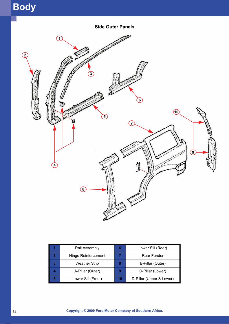
Side Outer Panels
2
1
6
5
3
4
8
7
9
10
1 Rail Assembly 6 Lower Sill (Rear)
2 Hinge Reinforcement 7 Rear Fender
3 Weather Strip 8 B-Pillar (Outer)
4 A-Pillar (Outer) 9 D-Pillar (Lower)
5 Lower Sill (Front) 10 D-Pillar (Upper & Lower)
Body
Copyright © 2009 Ford Motor Company of Southern Africa. 35
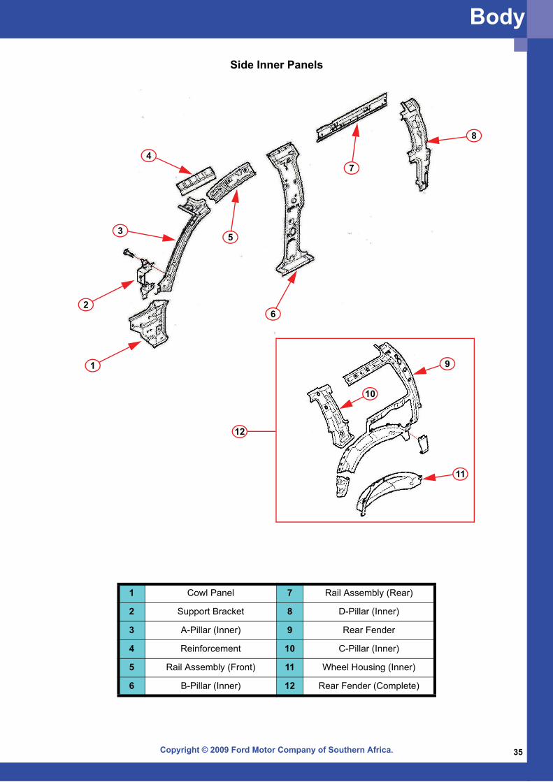
Side Inner Panels
1
8
4
6
7
53
2
10
11
9
12
1 Cowl Panel 7 Rail Assembly (Rear)
2 Support Bracket 8 D-Pillar (Inner)
3 A-Pillar (Inner) 9 Rear Fender
4 Reinforcement 10 C-Pillar (Inner)
5 Rail Assembly (Front) 11 Wheel Housing (Inner)
6 B-Pillar (Inner) 12 Rear Fender (Complete)
Body

Copyright © 2009 Ford Motor Company of Southern Africa.36
5
87
9
4
3
12
2
6
10
1 Tail Gate 6 Boot Stay
2 Hinge 7 Wedge
3 Weather Strip 8 Striker
4 Weather Strip 9 Striker
5 Adjuster 10 Finisher
Tailgate
Body
Copyright © 2009 Ford Motor Company of Southern Africa. 37
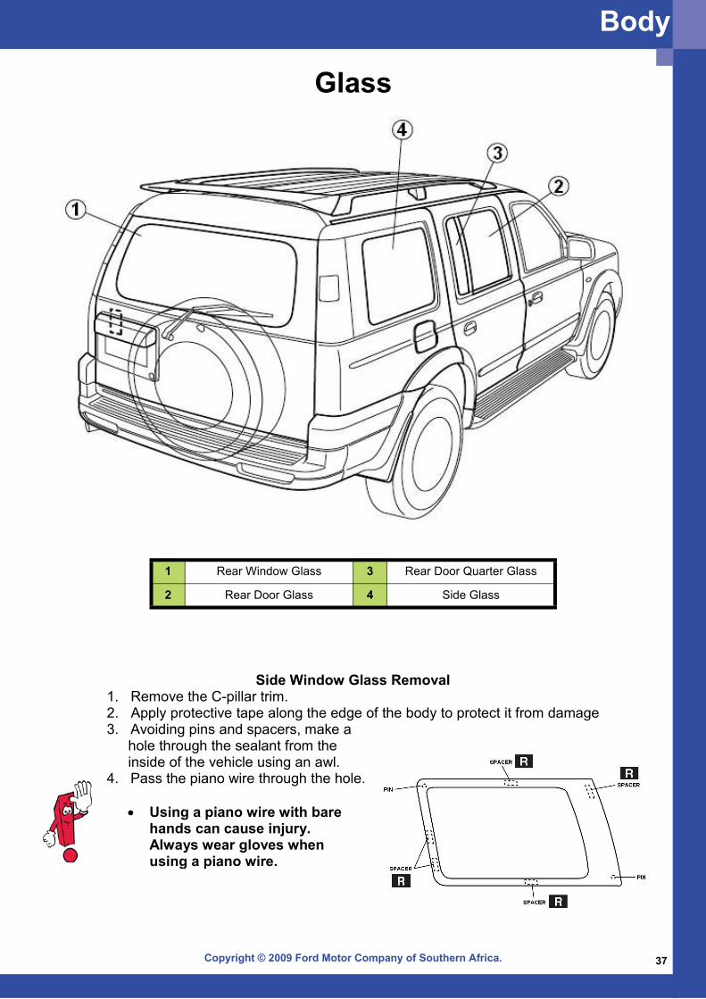
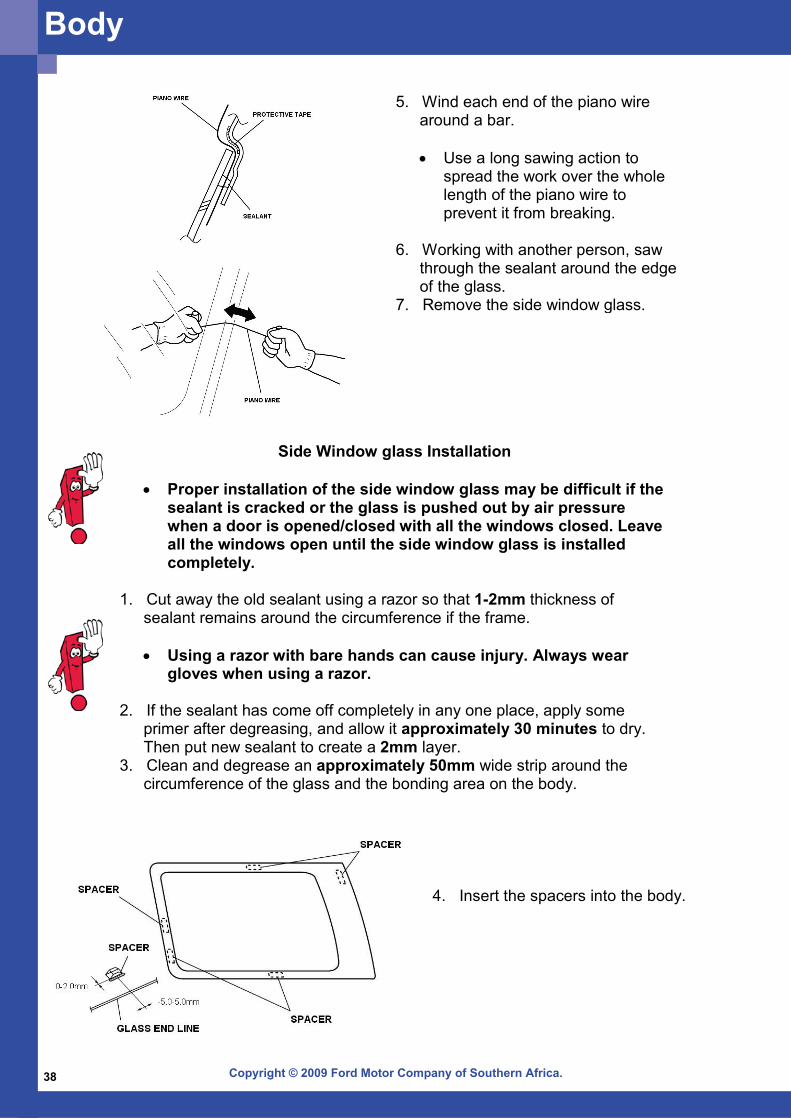
Side Window Glass Removal1. Remove the C-pillar trim. 2. Apply protective tape along the edge of the body to protect it from damage3. Avoiding pins and spacers, make a
hole through the sealant from the inside of the vehicle using an awl.
4. Pass the piano wire through the hole.
• Using a piano wire with bare hands can cause injury. Always wear gloves when using a piano wire.
Glass
1 Rear Window Glass 3 Rear Door Quarter Glass
2 Rear Door Glass 4 Side Glass
Body
Copyright © 2009 Ford Motor Company of Southern Africa.38
Body
5. Wind each end of the piano wire around a bar.
• Use a long sawing action to
spread the work over the whole length of the piano wire to prevent it from breaking.
6. Working with another person, saw
through the sealant around the edge of the glass.
7. Remove the side window glass.
Side Window glass Installation
• Proper installation of the side window glass may be difficult if the sealant is cracked or the glass is pushed out by air pressure when a door is opened/closed with all the windows closed. Leave all the windows open until the side window glass is installed completely.
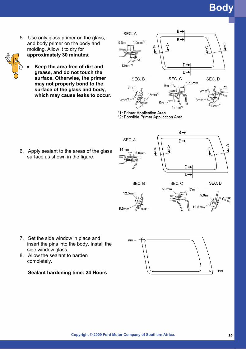
1. Cut away the old sealant using a razor so that 1-2mm thickness of
sealant remains around the circumference if the frame.
• Using a razor with bare hands can cause injury. Always wear gloves when using a razor.
2. If the sealant has come off completely in any one place, apply some
primer after degreasing, and allow it approximately 30 minutes to dry. Then put new sealant to create a 2mm layer.
3. Clean and degrease an approximately 50mm wide strip around the circumference of the glass and the bonding area on the body.
4. Insert the spacers into the body.
Copyright © 2009 Ford Motor Company of Southern Africa. 39
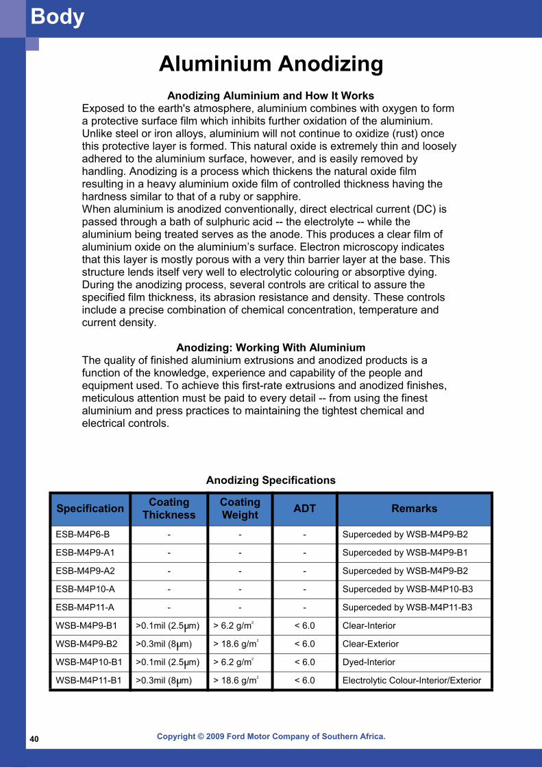
7. Set the side window in place and insert the pins into the body. Install the side window glass.
8. Allow the sealant to harden completely.
Sealant hardening time: 24 Hours
6. Apply sealant to the areas of the glass surface as shown in the figure.
5. Use only glass primer on the glass, and body primer on the body and molding. Allow it to dry for approximately 30 minutes.
• Keep the area free of dirt and
grease, and do not touch the surface. Otherwise, the primer may not properly bond to the surface of the glass and body, which may cause leaks to occur.
Body
Copyright © 2009 Ford Motor Company of Southern Africa.40
Specification Coating Thickness
Coating Weight ADT Remarks
ESB-M4P6-B - - - Superceded by WSB-M4P9-B2
ESB-M4P9-A1 - - - Superceded by WSB-M4P9-B1
ESB-M4P9-A2 - - - Superceded by WSB-M4P9-B2
ESB-M4P10-A - - - Superceded by WSB-M4P10-B3
ESB-M4P11-A - - - Superceded by WSB-M4P11-B3
WSB-M4P9-B1 >0.1mil (2.5 m) > 6.2 g/m < 6.0 Clear-Interior
WSB-M4P9-B2 >0.3mil (8 m) > 18.6 g/m < 6.0 Clear-Exterior
WSB-M4P10-B1 >0.1mil (2.5 m) > 6.2 g/m < 6.0 Dyed-Interior
WSB-M4P11-B1 >0.3mil (8 m) > 18.6 g/m < 6.0 Electrolytic Colour-Interior/Exterior
u
u
u
u
2
2
2
2
Anodizing Specifications
Body
Aluminium AnodizingAnodizing Aluminium and How It Works
Exposed to the earth's atmosphere, aluminium combines with oxygen to form a protective surface film which inhibits further oxidation of the aluminium. Unlike steel or iron alloys, aluminium will not continue to oxidize (rust) once this protective layer is formed. This natural oxide is extremely thin and loosely adhered to the aluminium surface, however, and is easily removed by handling. Anodizing is a process which thickens the natural oxide film resulting in a heavy aluminium oxide film of controlled thickness having the hardness similar to that of a ruby or sapphire. When aluminium is anodized conventionally, direct electrical current (DC) is passed through a bath of sulphuric acid -- the electrolyte -- while the aluminium being treated serves as the anode. This produces a clear film of aluminium oxide on the aluminium’s surface. Electron microscopy indicates that this layer is mostly porous with a very thin barrier layer at the base. This structure lends itself very well to electrolytic colouring or absorptive dying. During the anodizing process, several controls are critical to assure the specified film thickness, its abrasion resistance and density. These controls include a precise combination of chemical concentration, temperature and current density.
Anodizing: Working With Aluminium The quality of finished aluminium extrusions and anodized products is a function of the knowledge, experience and capability of the people and equipment used. To achieve this first-rate extrusions and anodized finishes, meticulous attention must be paid to every detail -- from using the finest aluminium and press practices to maintaining the tightest chemical and electrical controls.
Copyright © 2009 Ford Motor Company of Southern Africa. 41
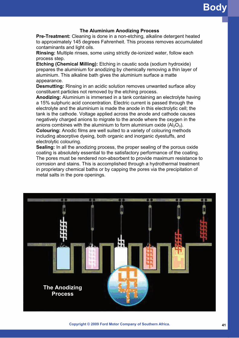
The Aluminium Anodizing ProcessPre-Treatment: Cleaning is done in a non-etching, alkaline detergent heated to approximately 145 degrees Fahrenheit. This process removes accumulated contaminants and light oils. Rinsing: Multiple rinses, some using strictly de-ionized water, follow each process step. Etching (Chemical Milling): Etching in caustic soda (sodium hydroxide) prepares the aluminium for anodizing by chemically removing a thin layer of aluminium. This alkaline bath gives the aluminium surface a matte appearance. Desmutting: Rinsing in an acidic solution removes unwanted surface alloy constituent particles not removed by the etching process. Anodizing: Aluminium is immersed in a tank containing an electrolyte having a 15% sulphuric acid concentration. Electric current is passed through the electrolyte and the aluminium is made the anode in this electrolytic cell; the tank is the cathode. Voltage applied across the anode and cathode causes negatively charged anions to migrate to the anode where the oxygen in the anions combines with the aluminium to form aluminium oxide (Al2O3). Colouring: Anodic films are well suited to a variety of colouring methods including absorptive dyeing, both organic and inorganic dyestuffs, and electrolytic colouring. Sealing: In all the anodizing process, the proper sealing of the porous oxide coating is absolutely essential to the satisfactory performance of the coating. The pores must be rendered non-absorbent to provide maximum resistance to corrosion and stains. This is accomplished through a hydrothermal treatment in proprietary chemical baths or by capping the pores via the precipitation of metal salts in the pore openings.
The AnodizingProcess
Body
Copyright © 2009 Ford Motor Company of Southern Africa.42
NOT GOOD
NOT GOODGOOD
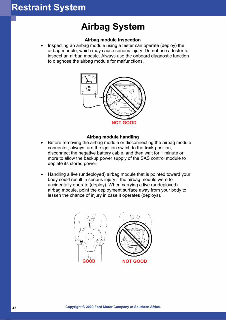
Airbag SystemAirbag module inspection
• Inspecting an airbag module using a tester can operate (deploy) the airbag module, which may cause serious injury. Do not use a tester to inspect an airbag module. Always use the onboard diagnostic function to diagnose the airbag module for malfunctions.
Airbag module handling• Before removing the airbag module or disconnecting the airbag module
connector, always turn the ignition switch to the lock position, disconnect the negative battery cable, and then wait for 1 minute or more to allow the backup power supply of the SAS control module to deplete its stored power.
• Handling a live (undeployed) airbag module that is pointed toward your
body could result in serious injury if the airbag module were to accidentally operate (deploy). When carrying a live (undeployed) airbag module, point the deployment surface away from your body to lessen the chance of injury in case it operates (deploys).
Restraint System

Copyright © 2009 Ford Motor Company of Southern Africa. 43
SAS control module handling• Remove the SAS control module or disconnecting the SAS control
module connector with the ignition switch at the ON position can activate the sensor in the SAS control module and operate (deploy) the airbags and pre-tensioner seat belts, which may cause serious injury. Before removing the SAS control module or disconnecting the SAS control module connector, always turn the ignition switch to the LOCK position, disconnect the negative battery cable, and wait for 1 minute or more to allow the backup power supply of the SAS control module to deplete its stored power.
• Connecting the SAS control module connector with the SAS control
module not securely fixed to the vehicle is dangerous. The sensor in the SAS control module could send an electrical signal to the airbag modules and pre-tensioner seat belts. This will operate (deploy) the airbags and pre-tensioner seat belts, which may result in serious injury. Therefore, before connecting the connector, securely fix the SAS control module to the vehicle.
• Because a sensor is built into the SAS control module, once the airbag
and pre-tensioner seat belts have operated (deployed) due to a collision or other causes, the SAS control module must be replaced with a new one even if the used one does not have any visible external damage or deformation. The used SAS control module may have been damaged internally, which may cause improper operation. If the SAS control module is reused, the airbags and pre-tensioner seat belts may not operate (deploy) normally, which could result in a serious accident. Always replace the SAS control module with a new one. The SAS control module cannot be bench-checked or self-checked.
• A live (undeployed) airbag module placed with its deployment surface to ground is dangerous. If the airbag module were to accidentally operate (deploy), it could cause serious injury. Always place a live (undeployed) airbag module with its deployment surface up.
NOT GOODGOOD
Restraint System
Copyright © 2009 Ford Motor Company of Southern Africa.44
Side airbag module handling• When a side airbag module operates (deploys) due to a collision, the
interior of the seat back (pad, frame, trim) may become damaged. If a side airbag does not operate (deploy) normally from a seat back that has been reused, a serious accident may result. After a side airbag has operated (deployed), always replace both the side airbag module and the seat back (pad, frame, trim) with new parts. After servicing, verify that the seat operates normally and that the wiring harness is not caught.
Crash zone sensor handling • Removing the crash zone sensor or disconnecting the crash zone
sensor connector with the ignition switch at the ON position can activate the crash zone sensor and operate (deploy) the airbags and pre-tensioner seat belts, which may cause serious injury. Before removing the crash zone sensor or disconnecting the crash zone sensor connector, always turn the ignition switch to the LOCK position, disconnect the negative battery cable, and then wait 1 minute or more to allow the backup power supply of the SAS control module to deplete its stored power.
• If the crash zone sensor is subjected to shock or the sensor is
disassembled, the airbags and pre-tensioner seat belts may accidentally operate (deploy) and cause injury, or the system may fail to operate normally and cause a serious accident. Do not subject the crash zone sensor to shock or disassemble the sensor.
• Because a sensor is built into the crash zone sensor, once the airbags
and pre-tensioner seat belts have operated (deployed) due to a collision or other causes, the crash zone sensor must be replaced with a new one even if the used one does not have any visible external damage or deformation. If the crash zone sensor is reused, the airbags and pre-tensioner seat belts may not operate (deploy) normally, which could result in a serious accident. Always replace the crash zone sensor with a new one. The crash zone sensor cannot be bench-checked or self-checked.
Side airbag sensor handling• Removing the side airbag sensor or disconnecting the side airbag
sensor connector with the ignition switch at the ON position can activate the side airbag sensor and operate (deploy) the airbags and pre-tensioner seat belts, which may cause serious injury. Before removing the side airbag sensor or disconnecting the side airbag sensor connector, always turn the ignition switch to the LOCK position, disconnect the negative battery cable, and then wait 1 minute or more to allow the backup power supply of the SAS control module to deplete its stored power.
Restraint System
Copyright © 2009 Ford Motor Company of Southern Africa. 45
NOT GOOD
• If the side airbag sensor is subjected to shock or the sensor is disassembled, the airbags and pre-tensioner seat belts may accidentally operate (deploy) and cause injury, or the system may fail to operate normally and cause a serious accident. Do not subject the side airbag sensor to shock or disassemble the sensor.
• Because a sensor is built into the side airbag sensor, once the airbags
and pre-tensioner seat belts have operated (deployed) due to a collision or other causes, the side airbag sensor must be replaced with a new one even if the used one does not have any visible external damage or deformation. If the side airbag sensor is reused, the airbags and pre-tensioner seat belts may not operate (deploy) normally, which could result in a serious accident. Always replace the side airbag sensor with a new one. The side airbag sensor cannot be bench-checked or self-checked.
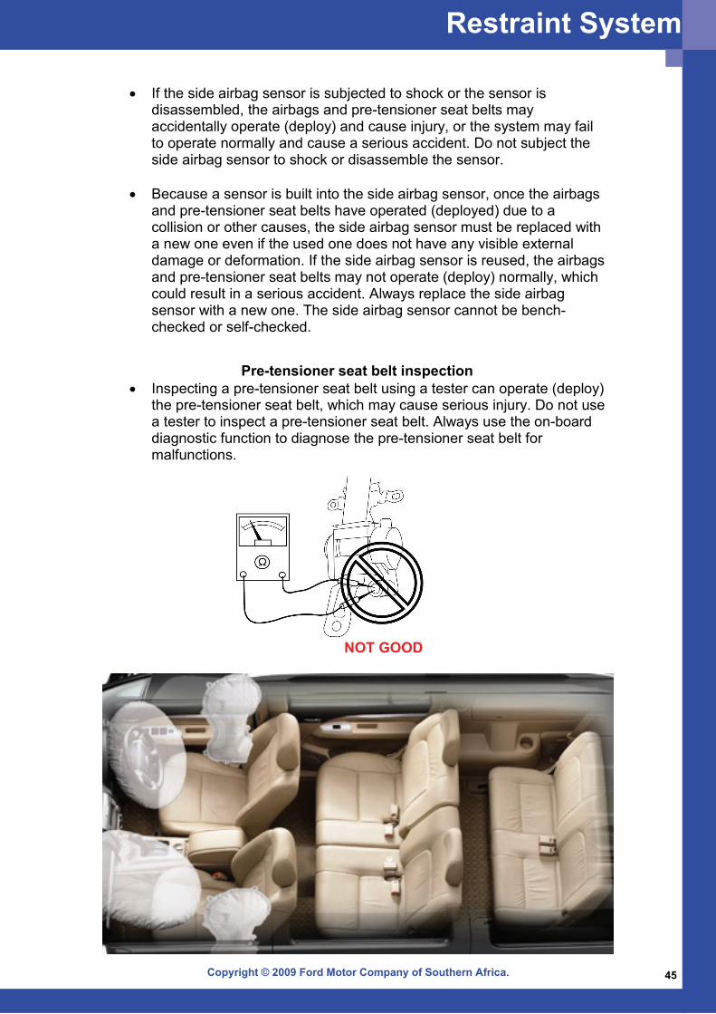
Pre-tensioner seat belt inspection • Inspecting a pre-tensioner seat belt using a tester can operate (deploy)
the pre-tensioner seat belt, which may cause serious injury. Do not use a tester to inspect a pre-tensioner seat belt. Always use the on-board diagnostic function to diagnose the pre-tensioner seat belt for malfunctions.
Restraint System
Copyright © 2009 Ford Motor Company of Southern Africa.46
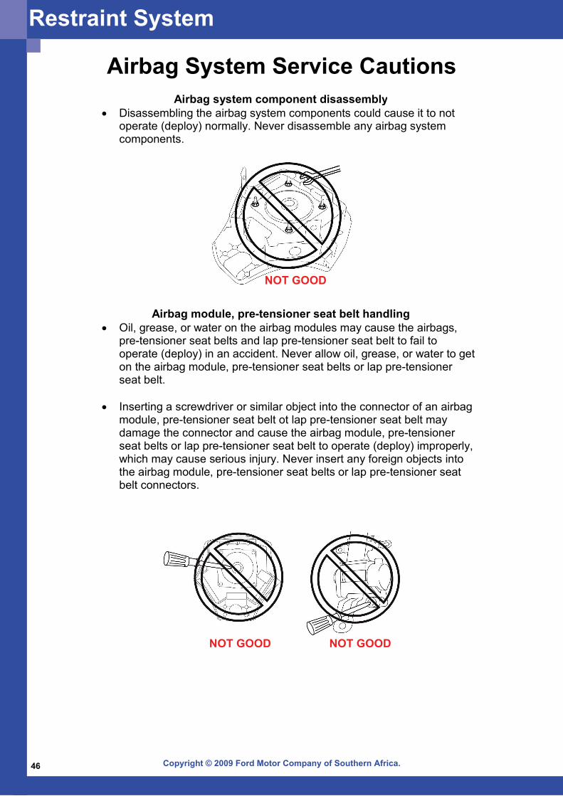
Airbag System Service CautionsAirbag system component disassembly
• Disassembling the airbag system components could cause it to not operate (deploy) normally. Never disassemble any airbag system components.
Airbag module, pre-tensioner seat belt handling • Oil, grease, or water on the airbag modules may cause the airbags,
pre-tensioner seat belts and lap pre-tensioner seat belt to fail to operate (deploy) in an accident. Never allow oil, grease, or water to get on the airbag module, pre-tensioner seat belts or lap pre-tensioner seat belt.
• Inserting a screwdriver or similar object into the connector of an airbag
module, pre-tensioner seat belt ot lap pre-tensioner seat belt may damage the connector and cause the airbag module, pre-tensioner seat belts or lap pre-tensioner seat belt to operate (deploy) improperly, which may cause serious injury. Never insert any foreign objects into the airbag module, pre-tensioner seat belts or lap pre-tensioner seat belt connectors.
NOT GOOD
NOT GOOD NOT GOOD
Restraint System
Copyright © 2009 Ford Motor Company of Southern Africa. 47
NOT GOOD
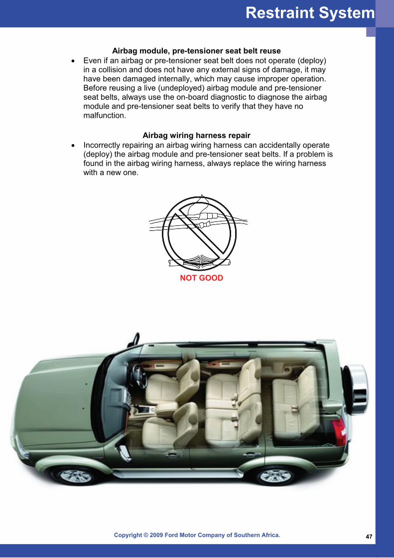
Airbag module, pre-tensioner seat belt reuse • Even if an airbag or pre-tensioner seat belt does not operate (deploy)
in a collision and does not have any external signs of damage, it may have been damaged internally, which may cause improper operation. Before reusing a live (undeployed) airbag module and pre-tensioner seat belts, always use the on-board diagnostic to diagnose the airbag module and pre-tensioner seat belts to verify that they have no malfunction.
Airbag wiring harness repair • Incorrectly repairing an airbag wiring harness can accidentally operate
(deploy) the airbag module and pre-tensioner seat belts. If a problem is found in the airbag wiring harness, always replace the wiring harness with a new one.
Restraint System
Copyright © 2009 Ford Motor Company of Southern Africa.48
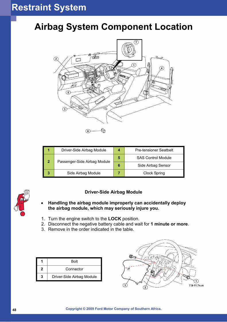
1 Driver-Side Airbag Module 4 Pre-tensioner Seatbelt
2 Passenger-Side Airbag Module5 SAS Control Module
6 Side Airbag Sensor
3 Side Airbag Module 7 Clock Spring
Airbag System Component Location
1
2
5
3
4
6
7
Driver-Side Airbag Module
• Handling the airbag module improperly can accidentally deploy the airbag module, which may seriously injure you.
1. Turn the engine switch to the LOCK position. 2. Disconnect the negative battery cable and wait for 1 minute or more. 3. Remove in the order indicated in the table.
1 Bolt
2 Connector
3 Driver-Side Airbag Module1
23 7.9-11.7n.m
Restraint System
Copyright © 2009 Ford Motor Company of Southern Africa. 49
Side Airbag Module
• Handling the airbag module improperly can accidentally deploy the airbag module, which may seriously injure you.
• If the side airbag module is installed with debris in the seat back, the foreign material may be scattered when the side airbag module operates (deploys), causing injury. Verify that there is no foreign material in the seat back before installing the side airbag module.
1. Turn the engine switch to the LOCK position. 2. Disconnect the negative battery cable and wait for 1 minute or more. 3. Remove in the order indicated in the table.
4. Install in the reverse order of removal. 5. Turn the engine switch to the ON position. 6. Verify that the airbag system warning light illuminates for approximately 6 seconds and goes out.
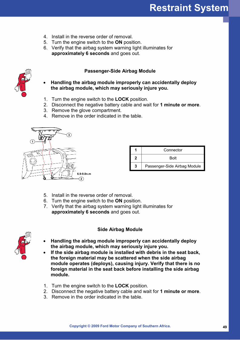
Passenger-Side Airbag Module
• Handling the airbag module improperly can accidentally deploy the airbag module, which may seriously injure you.
1. Turn the engine switch to the LOCK position. 2. Disconnect the negative battery cable and wait for 1 minute or more. 3. Remove the glove compartment. 4. Remove in the order indicated in the table.
1 Connector
2 Bolt
3 Passenger-Side Airbag Module
5. Install in the reverse order of removal. 6. Turn the engine switch to the ON position. 7. Verify that the airbag system warning light illuminates for approximately 6 seconds and goes out.
6.9-9.8n.m
1
2
3
Restraint System
Copyright © 2009 Ford Motor Company of Southern Africa.50
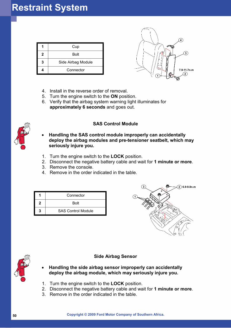
1 Cup
2 Bolt
3 Side Airbag Module
4 Connector 7.9-11.7n.m
12
3
4
4. Install in the reverse order of removal. 5. Turn the engine switch to the ON position. 6. Verify that the airbag system warning light illuminates for approximately 6 seconds and goes out.
1 Connector
2 Bolt
3 SAS Control Module
SAS Control Module
• Handling the SAS control module improperly can accidentally deploy the airbag modules and pre-tensioner seatbelt, which may seriously injure you.
1. Turn the engine switch to the LOCK position. 2. Disconnect the negative battery cable and wait for 1 minute or more. 3. Remove the console. 4. Remove in the order indicated in the table.
6.9-9.8n.m
1
23
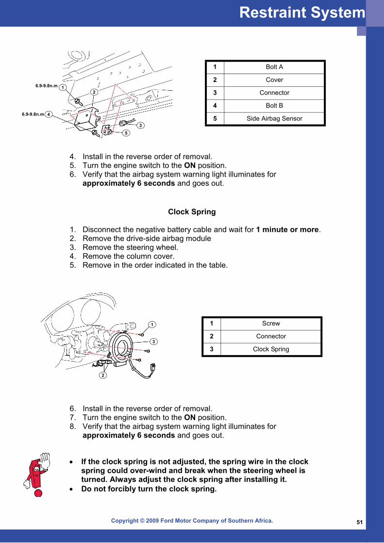
Side Airbag Sensor
• Handling the side airbag sensor improperly can accidentally deploy the airbag module, which may seriously injure you.
1. Turn the engine switch to the LOCK position. 2. Disconnect the negative battery cable and wait for 1 minute or more. 3. Remove in the order indicated in the table.
Restraint System
Copyright © 2009 Ford Motor Company of Southern Africa. 51
1 Bolt A
2 Cover
3 Connector
4 Bolt B
5 Side Airbag Sensor
6.9-9.8n.m
6.9-9.8n.m
12
35
4
4. Install in the reverse order of removal. 5. Turn the engine switch to the ON position. 6. Verify that the airbag system warning light illuminates for approximately 6 seconds and goes out.
Clock Spring
1. Disconnect the negative battery cable and wait for 1 minute or more. 2. Remove the drive-side airbag module 3. Remove the steering wheel. 4. Remove the column cover. 5. Remove in the order indicated in the table.
1 Screw
2 Connector
3 Clock Spring
1
2
3
6. Install in the reverse order of removal. 7. Turn the engine switch to the ON position. 8. Verify that the airbag system warning light illuminates for approximately 6 seconds and goes out.
• If the clock spring is not adjusted, the spring wire in the clock spring could over-wind and break when the steering wheel is turned. Always adjust the clock spring after installing it.
• Do not forcibly turn the clock spring.
Restraint System
Copyright © 2009 Ford Motor Company of Southern Africa.52
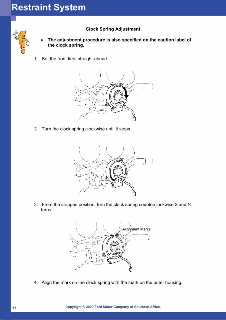
Clock Spring Adjustment
• The adjustment procedure is also specified on the caution label of the clock spring.
1. Set the front tires straight-ahead.
2. Turn the clock spring clockwise until it stops.
3. From the stopped position, turn the clock spring counterclockwise 2 and ¾turns.
4. Align the mark on the clock spring with the mark on the outer housing.
Alignment Marks
Restraint System
Copyright © 2009 Ford Motor Company of Southern Africa. 53
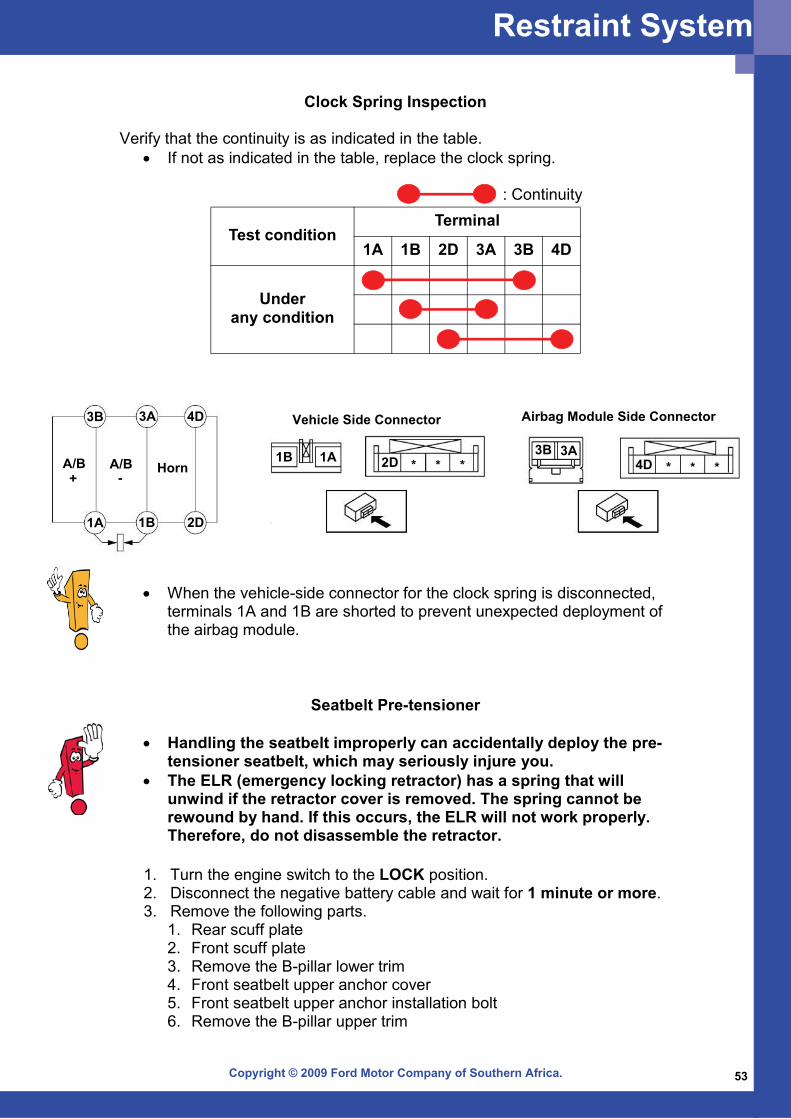
Test conditionTerminal
1A 1B 2D 3A 3B 4D
Under any condition
Clock Spring Inspection Verify that the continuity is as indicated in the table.
• If not as indicated in the table, replace the clock spring.
• When the vehicle-side connector for the clock spring is disconnected, terminals 1A and 1B are shorted to prevent unexpected deployment of the airbag module.
: Continuity
1B 1A 2D3B 3A
4D
Vehicle Side Connector Airbag Module Side Connector
HornA/B-+
A/B
1A 1B 2D
4D3A3B
* * * * * *
Seatbelt Pre-tensioner
• Handling the seatbelt improperly can accidentally deploy the pre-tensioner seatbelt, which may seriously injure you.
• The ELR (emergency locking retractor) has a spring that will unwind if the retractor cover is removed. The spring cannot be rewound by hand. If this occurs, the ELR will not work properly. Therefore, do not disassemble the retractor.
1. Turn the engine switch to the LOCK position. 2. Disconnect the negative battery cable and wait for 1 minute or more. 3. Remove the following parts.
1. Rear scuff plate 2. Front scuff plate 3. Remove the B-pillar lower trim 4. Front seatbelt upper anchor cover 5. Front seatbelt upper anchor installation bolt 6. Remove the B-pillar upper trim
Restraint System
Copyright © 2009 Ford Motor Company of Southern Africa.54
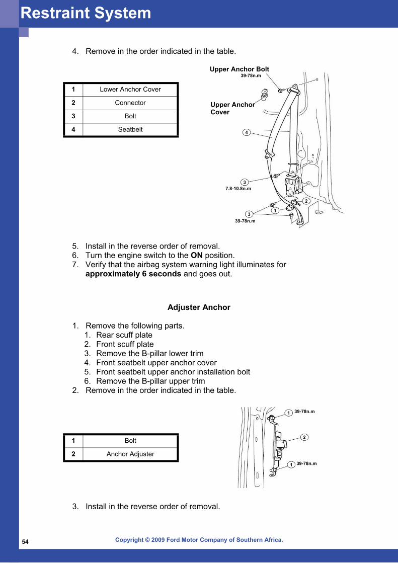
4. Remove in the order indicated in the table.
1 Lower Anchor Cover
2 Connector
3 Bolt
4 Seatbelt
1
2
3
4
3
Upper Anchor Bolt39-78n.m
Upper AnchorCover
7.8-10.8n.m
39-78n.m
5. Install in the reverse order of removal. 6. Turn the engine switch to the ON position. 7. Verify that the airbag system warning light illuminates for approximately 6 seconds and goes out.
Adjuster Anchor
1. Remove the following parts. 1. Rear scuff plate 2. Front scuff plate 3. Remove the B-pillar lower trim 4. Front seatbelt upper anchor cover 5. Front seatbelt upper anchor installation bolt 6. Remove the B-pillar upper trim
2. Remove in the order indicated in the table.
3. Install in the reverse order of removal.
1
2
1
39-78n.m
39-78n.m
1 Bolt
2 Anchor Adjuster
Restraint System
Copyright © 2009 Ford Motor Company of Southern Africa. 55
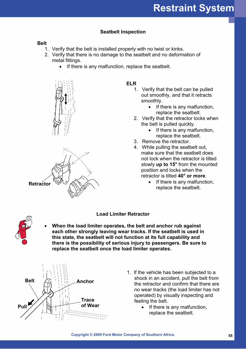
Seatbelt Inspection Belt
1. Verify that the belt is installed properly with no twist or kinks. 2. Verify that there is no damage to the seatbelt and no deformation of
metal fittings. • If there is any malfunction, replace the seatbelt.
ELR 1. Verify that the belt can be pulled
out smoothly, and that it retracts smoothly.
• If there is any malfunction, replace the seatbelt.
2. Verify that the retractor locks when the belt is pulled quickly.
• If there is any malfunction, replace the seatbelt.
3. Remove the retractor. 4. While pulling the seatbelt out,
make sure that the seatbelt does not lock when the retractor is tilted slowly up to 15° from the mounted position and locks when the retractor is tilted 40° or more.
• If there is any malfunction, replace the seatbelt.
Retractor
Load Limiter Retractor
• When the load limiter operates, the belt and anchor rub against each other strongly leaving wear tracks. If the seatbelt is used in this state, the seatbelt will not function at its full capability and there is the possibility of serious injury to passengers. Be sure to replace the seatbelt once the load limiter operates.
1. If the vehicle has been subjected to a shock in an accident, pull the belt from the retractor and confirm that there are no wear tracks (the load limiter has not operated) by visually inspecting and feeling the belt.
• If there is any malfunction, replace the seatbelt.
Anchor
Trace
Belt
Pull of Wear
Restraint System
Copyright © 2009 Ford Motor Company of Southern Africa.56
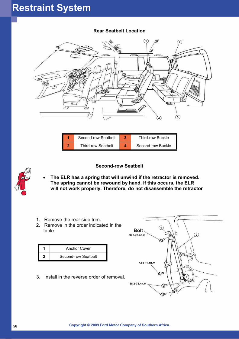
3. Install in the reverse order of removal.
1. Remove the rear side trim. 2. Remove in the order indicated in the
table.
Rear Seatbelt Location
1 Second-row Seatbelt 3 Third-row Buckle
2 Third-row Seatbelt 4 Second-row Buckle
1 2
34
Second-row Seatbelt
• The ELR has a spring that will unwind if the retractor is removed. The spring cannot be rewound by hand. If this occurs, the ELR will not work properly. Therefore, do not disassemble the retractor
1 Anchor Cover
2 Second-row Seatbelt7.65-11.5n.m
38.2-78.4n.mBolt
38.2-78.4n.m
1
2
Restraint System
Copyright © 2009 Ford Motor Company of Southern Africa. 57
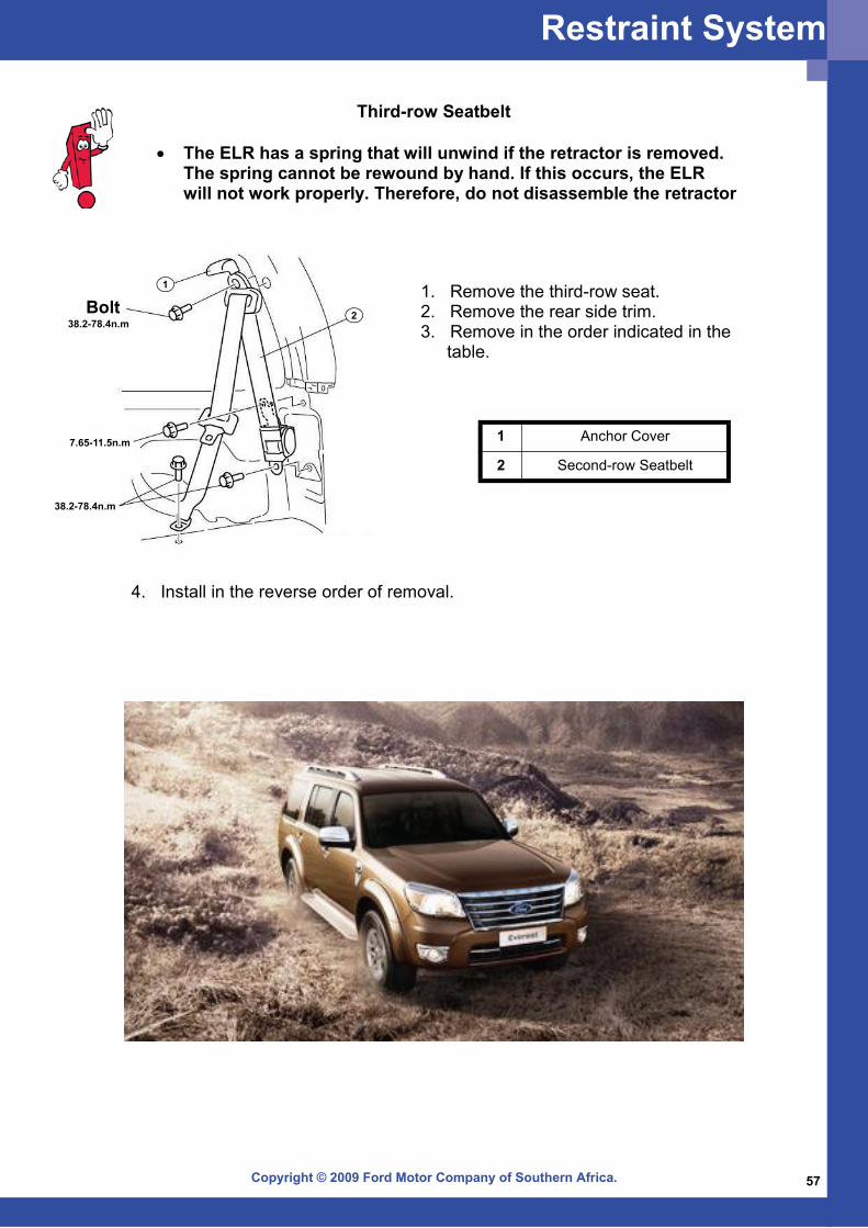
Third-row Seatbelt
• The ELR has a spring that will unwind if the retractor is removed. The spring cannot be rewound by hand. If this occurs, the ELR will not work properly. Therefore, do not disassemble the retractor
4. Install in the reverse order of removal.
1. Remove the third-row seat. 2. Remove the rear side trim. 3. Remove in the order indicated in the
table.
1 Anchor Cover
2 Second-row Seatbelt7.65-11.5n.m
38.2-78.4n.mBolt
38.2-78.4n.m
1
2
Restraint System

Copyright © 2009 Ford Motor Company of Southern Africa.58
The Wildtrak model features a number of stylistic and functional touches that distinguish it from other models in the Ranger line-up. Visually, the Wildtrak sports prominent decals on the doors and tailgate, along with silver roof rails, body-colour cladding and a body-coloured Wildtrak-branded sports bar. Other features include repeaters and puddle lamps integrated into the wing mirrors, a lockable tailgate with locking Armadillo cover, rear parking distance sensors, a Ford-branded load box liner and 18-inch diamond-cut alloy wheels. Model-specific interior appointments include Alcantara/leather seat and door trim with brushed aluminium accents and a healthy smattering of "Wildtrak" logos on the seats, scuff plate and carpets. Perhaps the most noticeable addition to the cabin is the Multi Meter atop the central facia section. This unit features an inclinometer/yaw meter, compass and digital ambient and outside temperature readouts.
Wildtrak Supplement
Wildtrak
Copyright © 2009 Ford Motor Company of Southern Africa. 59
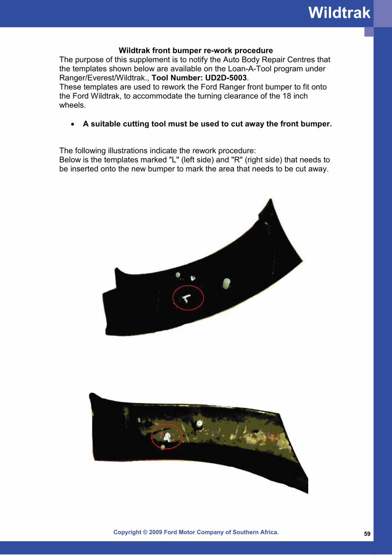
Wildtrak front bumper re-work procedureThe purpose of this supplement is to notify the Auto Body Repair Centres that the templates shown below are available on the Loan-A-Tool program under Ranger/Everest/Wildtrak., Tool Number: UD2D-5003. These templates are used to rework the Ford Ranger front bumper to fit onto the Ford Wildtrak, to accommodate the turning clearance of the 18 inch wheels.
• A suitable cutting tool must be used to cut away the front bumper.
The following illustrations indicate the rework procedure: Below is the templates marked "L" (left side) and "R" (right side) that needs to be inserted onto the new bumper to mark the area that needs to be cut away.
Wildtrak
Copyright © 2009 Ford Motor Company of Southern Africa.60
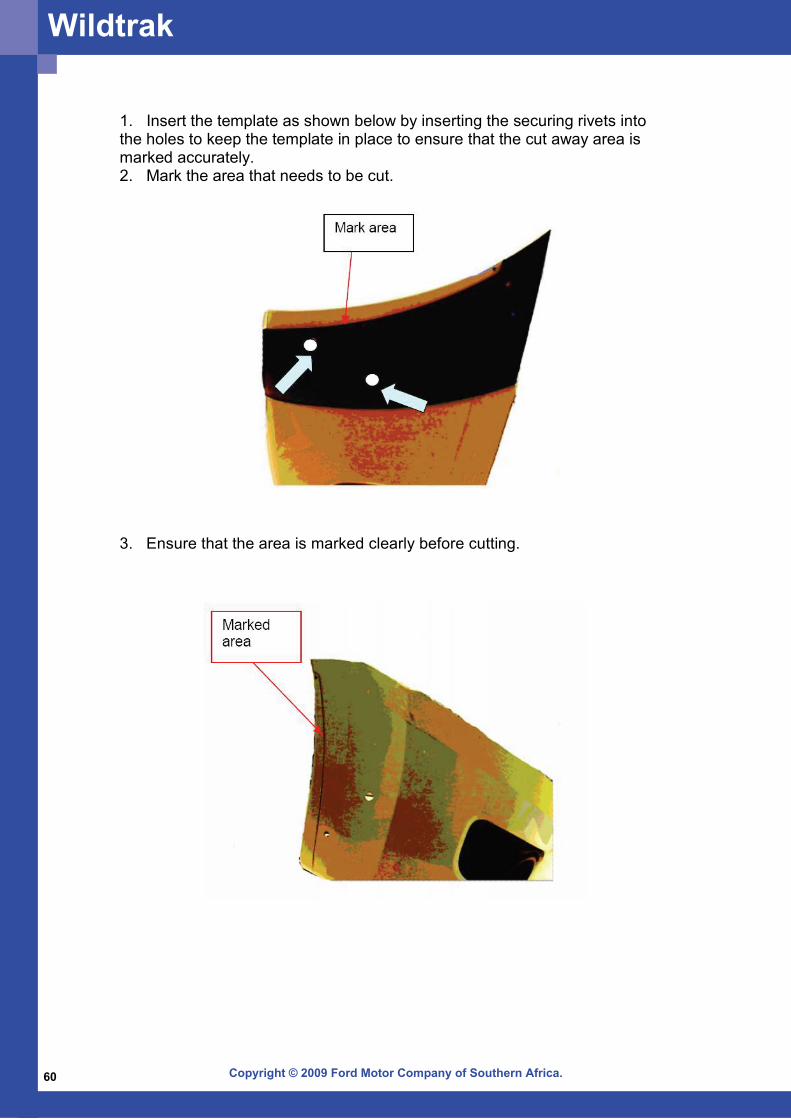
1. Insert the template as shown below by inserting the securing rivets into the holes to keep the template in place to ensure that the cut away area is marked accurately. 2. Mark the area that needs to be cut.
3. Ensure that the area is marked clearly before cutting.
Wildtrak

Copyright © 2009 Ford Motor Company of Southern Africa. 61
Notes:

Copyright © 2009 Ford Motor Company of Southern Africa.62
Notes:

Copyright © 2009 Ford Motor Company of Southern Africa.

www.fordabrc.co.za


![EVEREST Ultimate Edition ]------------------------------------------------------------------------------------ Version EVEREST v5.50.2100/fr Module de ...](https://static.fdocuments.us/doc/165x107/5aa972ce7f8b9a90188cd90e/everest-ultimate-edition-.jpg)


![Ford Everest Manual[1]](https://static.fdocuments.us/doc/165x107/55cf9803550346d03394fd56/ford-everest-manual1.jpg)
