
Force W - Ferroli
16
Force W High power modular generator
Transcript of Force W - Ferroli

Force WHigh power modular generator

MODULAR POWERFor new buildings and high-power upgrades
FORCE W is a family of high-power condensation modular generators designed to fully meet design requirements in the field of new buildings and upgrades of central heating systems.
FORCE W range generators can be installed individually or with up to four cascade modules for a maximum overall power of 600 kW.
The technical and construction features are in line with the highest standards requested by professionals in the central heating systems industry.
The efficiency of the FORCE W range enables the purchaser to apply for current tax benefits to upgrade climate-control systems.
F O R C E W
mod. 60 / 80 / 99 / 120 / 150
THE RANGE
mod. W 60HEAT INPUT 58.0 KWEFFECTIVE HEATING OUTPUT (50°C-30°C) 61.5 KWCLASS ERP A
mod. W 80HEAT INPUT 74.4 KWEFFECTIVE HEATING OUTPUT (50°C-30°C) 77.0 KWMAX P EFFICIENCY (50°C-30°C) 103.5
the range consists of 5 generators, certified B23, with an open chamber and forced draught
mod. W 99HEAT INPUT 96.6 KWEFFECTIVE HEATING OUTPUT (50°C-30°C) 100 KWMAX P EFFICIENCY (50°C-30°C) 103.5
mod. W 120HEAT INPUT 113.0 KWEFFECTIVE HEATING OUTPUT (50°C-30°C) 117 KWMAX P EFFICIENCY (50°C-30°C) 103.5
mod. W 150HEAT INPUT 143 KWEFFECTIVE HEATING OUTPUT (50°C-30°C) 148 KWMAX P EFFICIENCY (50°C-30°C) 103.5

Remote control of boiler parameters via remote control
REMOTE
Appliance certified as “range rated” according to UNI EN 483
RANGE RATED
F O R C E W
mod. 60 / 80 / 99 / 120 / 150
NOX
CLASS 6
-5.C
PROTECTED
CLIMATIC Device operates with climatic control and sliding system temperature (optional external temperature probe)
CASCADE Cascade operationDevice suitable for operation in a partially protected place with a minimum temperature of -5°C, as standard
Minimum polluting emissions(class 6 according to EN 15502-1) as required by Directive ErP of 26.09.2018 (NOx emissions < 56mg/kWh)
THE PRODUCT IN BRIEF
CHARACTERISTICSProduct benefits
> High power thermal condensing module,
designed for single installations or in banks up to
600 kW
> Hydraulic, gas and flue gas accessories for bank
installation, with 2, 3 and 4 modules
> Heat exchanger with pre-assembled elements
in aluminium-silicon alloy designed to achieve
maximum exchange efficiency and low pressure
drops on the water circuit
> Full pre-mixing combustion unit with metal
f ibre micro-flame burner with very low polluting
emissions (Class 6 according to EN 15502-1). The
modules can run on Methane and LPG
> Generator protection systems:
* Double sensor (delivery and return) system for
operation at ∆T constant (adjustable from 0 to
60°C)
* Exchanger overtemperature protection sensor
calibrated at 95°C
* Flue gas safety sensor
* Water pressure switch with minimum threshold of
0.8 bar
> Hydraulic unit (provided as an accessory) with
three-way shut-off valve for discharge into the
atmosphere and option of choosing between two
circulators, standard and high head
> Air / Flue gas circuit with intake in the installation
site and check valve on the flue gas ejection duct
to size the pressurised manifold
> Module bank management with self-configurating
Master / Slave system and option of setting the
generator on/off sequence
> Electronics on board the machine to manage a
system with two direct zones and one DHW
storage or systems with differentiated temperatures
(direct and mixed) in combination with the FZ4 B
temperature control unit
> Range Rated certif ied generator to adjust the
generated power to the system’s needs by
increasing the efficiency of the system and
preserving the mechanics of the machine
> The modules can be controlled and operated
remotely:
* Power or temperature adjustment with 0 - 10V
signal
* Blocking alarm signal for safety and to restart
operation
* Opentherm (OT) and Modbus communication
protocols with settable parameters

Pre-mixing unit
Burner
SILENCER The combustion unit can operate with Methane, LPG and Propane air with conversion kits that can be installed by authorised service technicians. The pre-mixing unit, combined with the low NOx micro-flame burner, has allowed for the Class 6 certification of the generator in accordance with UNI 15502-1
Aluminium heat exchanger in AL/Si alloy single block obtained by die-casting. The water passages inside the heat exchanger are particularly wide to ensure low pressure drops. Completely wet combustion chamber integrated in the casting
Condensate collection manifold
Condensate discharge
Flue gas safety sensor 110°C
SWING CHECK VALVE A thermostat calibrated at 110°C has been installed on the flue gas manifold to ensure perfect operation of the flue gas exhaust together with a swing check valve with a gravity damper that prevents flue gas return into the boiler. Appliances provided with this device enable design engineers to size the pressurised flue gas channel
Water pressure switch min 0.8 bar
System delivery temperature sensor
System return temperature sensor
HEAT EXCHANGER OVER-TEMPERATURE SAFETY SENSORThe heat exchanger’s operating temperature is checked by three independent sensors that are positioned in three different detection points. This ensures maximum safety during operation and protects the heat exchanger, increasing its service life.Pressure gauge (the pressure can also be read on the display)
Boiler drain cock
Air bleed valve
Combustion analysis outlet
Safety valve 6 bar
System delivery ø 1’ 1/2
System return ø 1’ 1/2
Gas inlet ø 1’
Flue gas outlet ø 100
1
12
2
33
4
4 5
5
6
6
7
7
8
8
9
9
10
10
11
11
12
12
13
13
14
14
15
15
16
16
17
17
M
M
R
R
G
G
F
F
F O R C E W
mod. 60 / 80 / 99 / 120 / 150
FORCE W is provided without a circulator and hydraulic kit with the shut-off valves.For correct installation, the boiler must always be purchased complete with the following kits:
- Modulating circulator
- System hydraulic kit
FORCE WComponents

Characterised by a large dot matrix display and keys to set the basic
functions of the generator and to select the parameterisation menus.
The interface is designed to make it easier to read the parameters
and browse the menus, both for the USER to adjust and set the basic
functions and the TECHNICIAN for maintenance and advanced
parameters.
Two distinct levels of parameterisation can be accessed from the control
panel’s main menu:
CHARACTERISTICSControl panel
KEY1 Contextual key 12 Contextual key 23 Contextual key 34 Dot matrix display (example of main
screen)5 Menu navigation key6 Menu input/confirmation key7 Menu navigation key8 DHW/heating Manual/Automatic
operation key9 Summer/Winter mode selection key10 Economy/Comfort mode selection key11 Menu exit key12 Main menu key13 Home key (back to the main screen)14 Main switch
CONTEXTUAL KEYS (part. 1, 2, 3) are grey, have no silk-screen printing and can have a different meaning based on the selected menu. It is essential to follow the indications provided by the display (icons and text). For example, by using contextual key 2 (part. 2), it is possible to access information about the device, such as: the temperature of the sensors, the operating power, etc.
DIRECT KEYS (part. 8, 9, 10) always have the same function
MENU/NAVIGATION KEYSThe menu/navigation keys (part. 5, 6, 7, 11, 12, 13) are used to scroll through the various menus implemented in the control panel
F O R C E W
mod. 60 / 80 / 99 / 120 / 150
1 2
3
4 5 6
7
8 9
10
11 12
1314
TECHNICIAN levelSince it is password-protected, it enables the “authorised technician”
to check and modify the thresholds of each single component of the
generator and boiler system.
USER levelSince it is not password-protected, it enables the “system manager’’ to
set the operating mode of the single or cascade generator in order to
sync them as much as possible with the type of system based on user
requirements

For all “PROFESSIONAL’’ range high-power condensation heat exchangers, Ferroli uses a single electronic platform and the
same interface panel that is able to manage correct operation and safety of the generator, cascade installation and the main
components of a heating system for domestic hot water production.
CHARACTERISTICSControl electronics
REMOTE CONTROL
COMMUNICATION PROTOCOLS
Signal 0 – 10 Vdc
Modbus
Opentherm
POTENTIALOF THE
ELECTRONICBOARD
CIRCULATOR 1ST SYSTEM DIRECT
ZONE
Power supply 230 Vac - 50 Hz
CIRCULATOR 2ND SYSTEM DIRECT
ZONE/CIRCULATOR OR DHW
3-WAY VALVE
Power supply 230 Vac - 50 Hz
REMOTE RESET
MASTER SLAVE
COMMUNICATION
TEMPERATURE PROBE
CASCADE DELIVERY
DHW RECIRCULATION CIRCULATOR
Power supply 230 Vac - 50 Hz
MASTER-SLAVE
COMMUNICATION
HEATING REQUEST 2ND ZONE
(A.T. or remote control timer)
DOMESTIC HOT WATER
REQUEST
(A.T. or remote control timer)
ANTILEGIONELLA ON/
BURNER ON SIGNAL REMOTE
CONTROL
SUPPORT CONTACT
Power supply 230 Vac - 50 Hz
HEATING REQUEST 1ST ZONE
(A.T. or remote control timer)
FAULT SIGNAL REMOTE CONTROL
Power supply 230 Vac - 50 Hz
INPUT OUTPUT
F O R C E W
mod. 60 / 80 / 99 / 120 / 150
KEY (referred to the diagrams on the next page)32 Boiler circulator 72a Room thermostat 1st zone (mixed) 72b Room thermostat 2nd zone (mixed) 72c Room thermostat 3rd zone (direct) 138 External probe 139a Remote timer control 1st zone (mixed) 139b Remote timer control 2nd zone (mixed) 139c Remote timer control 3rd zone (direct) 155 Storage tank probe 300 Antilegionella circulator 315a Mixing valve 1st zone (mixed) [ A = OPENING PHASE B = NEUTRAL C = CLOSING PHASE] 315b Mixing valve 2nd zone (mixed) [A = OPENING PHASE B = NEUTRAL C = CLOSING PHASE] 317a Safety thermostat 1st zone (mixed) 317b Safety thermostat 2nd zone (mixed) 318a Circulator 1st zone (mixed) 318b Circulator 2nd zone (mixed) 318c Circulator 3rd zone (direct) 319a Delivery sensor 1st zone (mixed) 319b Delivery sensor 2nd zone (mixed) a 1st zone (mixed) b 2nd zone (mixed) c 3rd zone (direct) d Storage tank circuit FZ4 B Zone control card PHE Steel plate heat exchanger

In the event of FORCE W installation in a direct two-zone system (such as a heating circuit and DHW production), the
standard electronics can manage the system autonomously without using any optional external equipment.
With regard to mixed systems with high and low operating temperature, the boiler must be coupled with the FZ4 B
temperature control module designed to manage a heating system up to three zones, two of which mixed.
CHARACTERISTICSControl electronics
F O R C E W
mod. 60 / 80 / 99 / 120 / 150
CASE A: REPLACEMENT OF THE EXISTING GENERATOR ON A HIGH TEMPERATURE SYSTEM
Thermal system with two loops separated by a plate heat exchanger (PHE). The primary circuit is fed by two FORCE W modules
connected as a bank operating in AUTO-CASCADE mode managed directly by the boiler electronics. A “direct” high temperature
circuit and a DHW storage with recirculation pump are connected on the secondary circuit (system side).
In addition to SLAVE thermal unit management, without any additional equipment, the MASTER generator can control the system’s
main components.
CASE B: NEWLY DESIGNED SYSTEM
Thermal system with two loops separated by a plate heat exchanger (PHE). The primary circuit is fed by two FORCE W modules
connected as a bank operating in AUTO-CASCADE mode managed directly by the boiler electronics. The secondary circuit is
composed of two mixed low temperature “zones”, a high temperature direct one and a DHW storage. The MASTER generator
controls DHW production directly, in addition to managing the SLAVE thermal unit. The heating zones are controlled by card FZ4
B, connected to the generators through Open Therm.
32
138
32
289 M95
306
a b
300MASTER SLAVE
155
72
PHE
32
138
32
289
Ma d
MASTER SLAVE
FZ4B
INAIL
72/139a 72/139b
317a
319a
315a
318a
Mb
317b
319b
315b
318b
72/139c
155
c
318c 130PHE
32
138
32
289
Ma d
MASTER SLAVE
FZ4B
INAIL
72/139a 72/139b
317a
319a
315a
318a
Mb
317b
319b
315b
318b
72/139c
155
c
318c 130
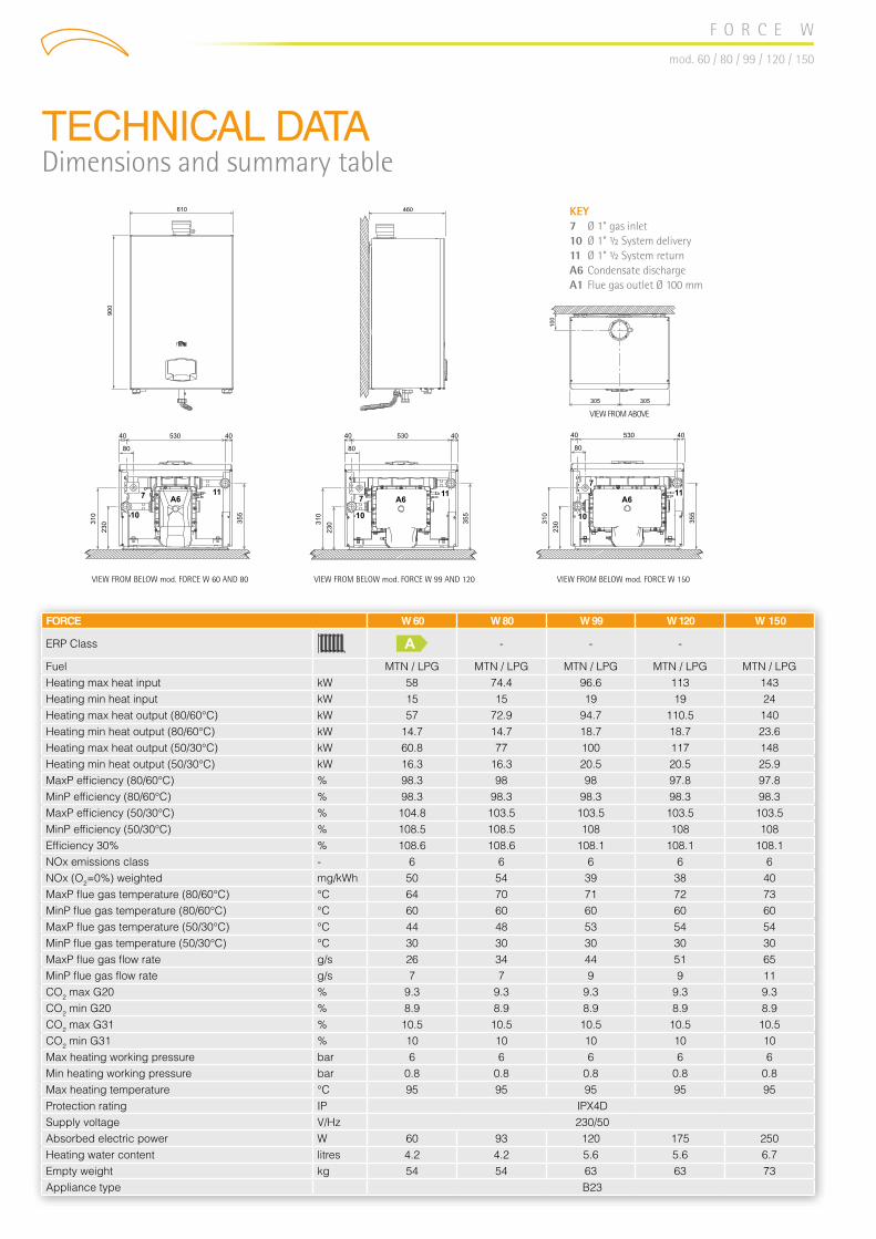
TECHNICAL DATADimensions and summary table
F O R C E W
mod. 60 / 80 / 99 / 120 / 150
KEY7 Ø 1” gas inlet10 Ø 1” ½ System delivery11 Ø 1” ½ System returnA6 Condensate dischargeA1 Flue gas outlet Ø 100 mm
VIEW FROM ABOVE
VIEW FROM BELOW mod. FORCE W 99 AND 120VIEW FROM BELOW mod. FORCE W 60 AND 80 VIEW FROM BELOW mod. FORCE W 150
FORCE W 60 W 80 W 99 W 120 W 150
ERP Class A - - -
Fuel MTN / LPG MTN / LPG MTN / LPG MTN / LPG MTN / LPGHeating max heat input kW 58 74.4 96.6 113 143Heating min heat input kW 15 15 19 19 24Heating max heat output (80/60°C) kW 57 72.9 94.7 110.5 140Heating min heat output (80/60°C) kW 14.7 14.7 18.7 18.7 23.6Heating max heat output (50/30°C) kW 60.8 77 100 117 148Heating min heat output (50/30°C) kW 16.3 16.3 20.5 20.5 25.9MaxP efficiency (80/60°C) % 98.3 98 98 97.8 97.8MinP efficiency (80/60°C) % 98.3 98.3 98.3 98.3 98.3MaxP efficiency (50/30°C) % 104.8 103.5 103.5 103.5 103.5MinP efficiency (50/30°C) % 108.5 108.5 108 108 108Efficiency 30% % 108.6 108.6 108.1 108.1 108.1NOx emissions class - 6 6 6 6 6NOx (O2=0%) weighted mg/kWh 50 54 39 38 40MaxP flue gas temperature (80/60°C) °C 64 70 71 72 73MinP flue gas temperature (80/60°C) °C 60 60 60 60 60MaxP flue gas temperature (50/30°C) °C 44 48 53 54 54MinP flue gas temperature (50/30°C) °C 30 30 30 30 30MaxP flue gas flow rate g/s 26 34 44 51 65MinP flue gas flow rate g/s 7 7 9 9 11CO2 max G20 % 9.3 9.3 9.3 9.3 9.3CO2 min G20 % 8.9 8.9 8.9 8.9 8.9CO2 max G31 % 10.5 10.5 10.5 10.5 10.5CO2 min G31 % 10 10 10 10 10Max heating working pressure bar 6 6 6 6 6Min heating working pressure bar 0.8 0.8 0.8 0.8 0.8Max heating temperature °C 95 95 95 95 95Protection rating IP IPX4D Supply voltage V/Hz 230/50 Absorbed electric power W 60 93 120 175 250Heating water content litres 4.2 4.2 5.6 5.6 6.7Empty weight kg 54 54 63 63 73Appliance type B23

TECHNICAL DATADiagrams of generator pressure drops
TECHNICAL DATACharacteristic circulator head/flow rate curves
F O R C E W
mod. 60 / 80 / 99 / 120 / 150
FORCE W 60 - FORCE W 80 - FORCE W 99 - FORCE W 120
m H
2O
m H
2O
FORCE W 150
CIRCULATOR KIT7 m
CIRCULATOR KIT10 m
10-METRE CIRCULATOR KIT∆P constant∆P variable
10-METRE CIRCULATOR KITconstant speed
7-METRE CIRCULATOR KIT∆P constant∆P variable
7-METRE CIRCULATOR KITconstant speed
Flow rate - m3/h Flow rate - m3/h

GENERATORS COIL MODULES
HEAT INPUT HEAT OUTPUT CASCADE MODULATION
50 / 30°C 80 / 60°C MinP - MaxP 50 / 30°C1 2 3 4 kW kW kW kW MinP / MaxP
60 60 2 116.0 123.0 113.0 15.7 - 123.0 1:860 80 2 132.4 138.5 129.4 15.7 - 138.5 1:980 80 2 148.8 154.0 145.8 14.7 - 154.0 1:1060 120 2 171.0 178.5 166.8 15.7 - 178.5 1:1180 120 2 187.4 194.0 183.2 14.7 - 194.0 1:1399 120 2 209.6 217.0 204.9 20.5 - 217.0 1:10
120 120 2 226.0 234.0 220.6 20.0 - 234.0 1:12120 150 2 272.0 265.0 250.3 20.0 - 265.0 1:13150 150 2 318.0 296.0 280.0 25.9 - 296.0 1:1199 120 120 3 322.6 334.0 315.2 20.5 - 334.0 1:16
120 120 120 3 339.0 351.0 330.9 20.0 - 351.0 1:1880 150 150 3 392.4 373.0 352.9 14.7 - 373.0 1:2599 150 150 3 414.6 396.0 374.6 20.5 - 396.0 1:19
120 150 150 3 431.0 413.0 390.3 20.0 - 413.0 1:21150 150 150 3 477.0 444.0 420.0 25.9 - 444.0 1:17120 120 120 120 4 452.0 468.0 441.2 20.0 - 468.0 1:2360 150 150 150 4 535.0 505.5 476.5 15.7 - 505.5 1:32
120 120 150 150 4 544.0 530.0 500.6 20.0 - 530.0 1:26120 150 150 150 4 590.0 561.0 530.3 20.0 - 561.0 1:28150 150 150 150 4 636.0 592.0 560.0 25.9 - 592.0 1:23
F O R C E W
mod. 60 / 80 / 99 / 120 / 150
CASCADE INSTALLATIONCharacteristics and strong points
1 The FORCE W range can be coupled in banks with 2, 3
and 4 generator combinations up to a maximum power of
approximately 600 kW, with a modulation ratio up to 1:32.
2 The dimensions of generators and positioning of fittings are
identical. All range models are perfectly interchangeable with
each other.
3 Each cascade configuration is complete with flue gas, hydraulic
and gas accessories.
4 FORCE W is fitted with a standard swing check valve that
prevents flue gas return into the boiler. This device enables
pressurised flue gas duct designs with much smaller and more
cost-effective diameters.
5 The electronics fitted as per standard was designed to
autonomously manage the dynamics of several generators
in cascade, with MASTER-SLAVE logic, with maximum 6
generators.
6 By setting the parameters of the cascade MASTER board, the
ignition sequence of the various modules can be set and
rotated so as to evenly divide the number of operating hours.
The FORCE W cascade system has been designed by drawing from Ferroli’s extensive experience in field of central heating
generators and with feedback from design engineers and installers. All boiler parts have designed to facilitate coil installation.
The generators are supplied (optional) with all the accessories for rapid, sound and safe cascade central heating installation:

F O R C E W
mod. 60 / 80 / 99 / 120 / 150
CASCADE INSTALLATIONOperating logic
The standard electronics installed on each FORCE W module can control a bank of 6 generators without using any optional
additional control units.
The logic chosen by the design engineers is MASTER / SLAVE and, when duly connected, it ensures that all coils work as a single
generator managed by a single control (MASTER) able to:
- Distinguish the number of generators installed and connected in bank and identify the system components connected to the
MASTER generator terminal board.
- Modify the burner’s ignition sequence independently in order to distribute the total number of operating hours equally.
- Using a specific parameter, it is possible to customise the switch-off logic of the bank generators (Parallel or Sequential), without
the need to resort to optional sequence control units or to additional control modules.
Sequential operation
The ignition and power modulation of the burners with sequential
operation enable a wide modulation range that runs from minimum
power of a single generator to a total maximum power of all burners
running together.
This makes the system more flexible compared to the system’s
heating requirements, but at the expense of the loss of a certain
degree of energy efficiency.
min
Q1 k
W
min
Q2 k
W
min
Q3 k
W
Generator 3Generator 2Generator 1
Parallel operation
Parallel operation of the modules provides for simultaneous ignition,
power modulation and switch-off of the burners.
This solution allows for maximum system efficiency since most
generators running at the lowest power enable maximum
condensation.
The modulation range of the system’s power is instead limited.
min
Q1 k
W
min
Q2 k
W
min
Q3 k
W
Generator 1 Generator 2 Generator 3
A 1st MASTER module
B 2nd SLAVE module
C 3rd SLAVE module
D 6th SLAVE module

CASCADE INSTALLATIONAccessories
F O R C E W
mod. 60 / 80 / 99 / 120 / 150
DESCRIPTION CODE
additional sensor for storage tank and/or system flow for cascade configurations with and without hydraulic separator
cable2 m 1KWMA11W
cable 5 m 043005X0
outdoor probe 013018X0
hydraulic separator DN 32For installation until 150 kW.The installer is responsible for the connection with the generator
042086X0
hydraulic separator DN 65For installation from 151 kW to 300 kW
042078X0
installation kit for hydraulic separator. For installation from 151 kW to 300 kW
042079X0
hydraulic separator DN 65For installation from 301 kW to 600 kW
042080X0
installation kit for hydraulic separator. For installation from 301 kW to 600 kW
042081X0
gasketed plates heat exchanger. The hydraulic connection between the generator and the exchanger is the responsibility of the installer.
Temperature controls
Neutralisers
6 7 1 2 3 4 8 9
Self-
stan
ding
fram
e (s
tart)
*
Self-
stan
ding
fram
e (e
xten
sion
)
7-m
mod
ulat
ing
circ
ulat
or
10-m
mod
ulat
ing
circ
ulat
or
FOR
CE
W h
ydra
ulic
kit
( 3-w
ay 1
”1/2
coc
k -
2-w
ay 1
” 1/
2 co
ck, 1
” 1/
2 ch
eck
valv
e)
hydr
aulic
(DN
65 d
eliv
ery
and
retu
rn),
gas
(DN
40) m
anifo
lds
kit f
or b
ank
inst
alla
tion
Blin
d fla
nge
kit
DN
65
Flue
gas
man
ifold
sta
rter k
it (Ø
200
mm
) *
Flue
gas
man
ifold
ext
ensi
on k
it (Ø
200
m
m) *
Pout(50/30°C)
MODULESFORCE W
Tot.
mod
ules
60 80 99 120 150 042076X0 042077X0 042070X0 042071X0 042072X0 042074X0 042073X0 041091X0 041092X0
62 1 1 1 - 1 1 1 1 1 - -77 1 1 1 - 1 1 1 1 1 - -98 1 1 1 - 1 1 1 1 1 - -117 1 1 1 - 1 1 1 1 1 - -148 1 1 1 - 1 1 1 1 1 - -124 2 2 1 1 2 2 2 2 1 1 2139 1 1 2 1 1 2 2 2 2 1 1 2154 2 2 1 1 2 2 2 2 1 1 2179 1 1 2 1 1 2 2 2 2 1 1 2194 1 1 2 1 1 2 2 2 2 1 1 2215 1 1 2 1 1 2 2 2 2 1 1 2234 2 2 1 1 2 2 2 2 1 1 2265 1 1 2 1 1 2 2 2 2 1 1 2296 2 2 1 1 2 2 2 2 1 1 2332 1 2 3 1 2 3 3 3 3 1 1 3351 3 3 1 2 3 3 3 3 1 1 3373 1 2 3 1 2 3 3 3 3 1 1 3394 1 2 3 1 2 3 3 3 3 1 1 3413 1 2 3 1 2 3 3 3 3 1 1 3444 3 3 1 2 3 3 3 3 1 1 3468 4 4 1 3 4 4 4 4 1 1 4530 2 2 4 1 3 4 4 4 4 1 1 4561 1 3 4 1 3 4 4 4 4 1 1 4592 4 4 1 3 4 4 4 4 1 1 4
ACCESSORIESNECESSARY TO CORRECTLY INSTALL FORCE W GENERATORSIN A BANK
ACCESSORIESUPON REQUEST FOR CONFIGURATION ACCORDING TO PROJECT SPECIFICATIONS
1 1 1 1
2 2 22
4
89
63
7

CASCADE INSTALLATIONFor outdoors
F O R C E W
mod. 60 / 80 / 99 / 120 / 150
A
B
G H L
C
E
* Flue gas accessories certified for installation in a utility room or in a protected place
A B C E G H L
Tech
nica
l cab
inet
equ
ippe
d fo
r ou
tdoo
rs
7-m
mod
ulat
ing
circ
ulat
or
10-m
mod
ulat
ing
circ
ulat
or
Blin
d fla
nge
kit
DN
65
Flue
gas
man
ifold
sta
rter k
it (Ø
20
0 m
m) *
Flue
gas
man
ifold
ext
ensi
on k
it (Ø
20
0 m
m) *
Flue
man
ifold
ada
pter
F 2
00 m
m
Smok
e ch
imne
y F
100
mm
(for u
npro
tect
ed ro
of in
stal
latio
ns)
Pout(50/30°C)
MODULESFORCE W
Tot.
mod
ules
60 80 99 120 150 046051X0 042070X0 042071X0 042073X0 041091X0 041092X0 041093X0 041094X0
62 1 1 1 1 1 1 - - - 177 1 1 1 1 1 1 - - - 198 1 1 1 1 1 1 - - - 1117 1 1 1 1 1 1 - - - 1148 1 1 1 1 1 1 - - - 1124 2 2 2 2 2 1 1 2 1 2139 1 1 2 2 2 2 1 1 2 1 2154 2 2 2 2 2 1 1 2 1 2179 1 1 2 2 2 2 1 1 2 1 2194 1 1 2 2 2 2 1 1 2 1 2215 1 1 2 2 2 2 1 1 2 1 2234 2 2 2 2 2 1 1 2 1 2265 1 1 2 2 2 2 1 1 2 1 2296 2 2 2 2 2 1 1 2 1 2332 1 2 3 3 3 3 1 1 3 2 3351 3 3 3 3 3 1 1 3 2 3373 1 2 3 3 3 3 1 1 3 2 3394 1 2 3 3 3 3 1 1 3 2 3413 1 2 3 3 3 3 1 1 3 2 3444 3 3 3 3 3 1 1 3 2 3468 4 4 4 4 4 1 1 4 3 4530 2 2 4 4 4 4 1 1 4 3 4561 1 3 4 4 4 4 1 1 4 3 4592 4 4 4 4 4 1 1 4 3 4
DESCRIPTION CODE
additional sensor for storage tank and/or system flow for cascade configurations with and without hydraulic separator
cable2 m 1KWMA11W
cable 5 m 043005X0
outdoor probe 013018X0
Single empty cabinet for outdoors 046055X0
Double empty cabinet for outdoors 046056X0
hydraulic separator DN 32. For installation until 150 kW. The installer is responsible for the connection with the generator
042086X0
hydraulic separator DN 65For installation from 151 kW to 300 kW
042078X0
installation kit for hydraulic separator. For installation from 151 kW to 300 kW
042079X0
hydraulic separator DN 65For installation from 301 kW to 600 kW
042080X0
installation kit for hydraulic separator. For installation from 301 kW to 600 kW
042081X0
gasketed plates heat exchanger. The hydraulic connection between the generator and the exchanger is the responsibility of the installer.
Temperature controls
Neutralisers
ACCESSORIESNECESSARY TO CORRECTLY INSTALL FORCE W GENERATORSIN A BANK
ACCESSORIESUPON REQUEST FOR CONFIGURATION ACCORDING TO PROJECT SPECIFICATIONS

F O R C E W
mod. 60 / 80 / 99 / 120 / 150
HYDRAULIC SEPARATORSCharacteristics - Accessories to complete installation
The hydraulic separator guarantees independence between the primary circuit (generator) and the secondary circuit (system)
without any disturbance or interference between them. The separator is proposed complete with deaerator, sludge separator and
is fully insulated.
CHARACTERISTICS: Max operating pressure: 6 bar - Temperature range: 0 -100°C - Connections: DN 32 / DN 65 / DN 100
COMPLETION ACCESSORIES
Additional sensor for storage tank and/or system delivery for cascade configurations with and without hydraulic separator2 m cable 1KWMA11W - 5 m cable 043005X0
90° PPS ø 80 mm bend kit041072X0
Kit for management with thermostat (not supplied) of a DHW storage tank (for heating only boilers)013017X0
90° bend kit in PPSø 80 mm 1KWMA01W - ø 100 mm 041077X0ø 200 mm 041060X0
Outdoor probe013018X0
1 m MF mm PPS flue gas duct kitø 80 1KWMA83W - ø 100 041073X0ø 200 041062X0
Temperature control - Plates ø 100 flue gas terminal1KWMA29K
M/F flue gas outlet reduction ø 100/80 mm 041090X0Neutralisers
760
1”
1”½
90
150
½"
300
300
270
120
½"
1”½
1”½
1”½
HYDRAULIC SEPARATOR INSTALLATIONS UP TO 150 KW MODEL DN 32 DN 65 DN 100Flow rate m3/h 6,5 18 30Capacity l 4,8 21 46Max temperature °C 100Max pressure bar 6Raw material - ST37.1 steelInsulation - EPP Black - 40 g/l
Hydraulic separator DN 32The installer is responsible for the connection with the generator042086X0
HYDRAULIC SEPARATOR INSTALLATIONS 301 - 600 kW
Hydraulic separator DN 100042080X0
DN 100 separator hydraulic connection manifolds042081X0
HYDRAULIC SEPARATOR INSTALLATIONS 151 - 300 kW
Hydraulic separator DN 65042078X0
DN 65 separator hydraulic connection manifolds042079X0

F O R C E W
mod. 60 / 80 / 99 / 120 / 150
Ferroli offers a full range of plate heat exchangers made of braze-welded steel for small and medium systems and a
type that can be inspected for systems up to approximately 1 MW.
PLATE EXCHANGERSPhe - She
- Stainless steel plate inspectable heat exchangers (AISI 316L), for medium and
small power systems
- Single-pass circuit in counter-current with four threaded stainless steel
connections (AISI 316)
- Plug-in NBR gaskets (installed without glue or silicones)
- The optional kits of ground support brackets and insulation are available for the
entire range
- Ideal for replacing a heat generator in an existing system or to combine it with
systems with high flow rates
- Maximum operating pressure: 10 bar
- Max operating temperature: 100°C
PHEHEAT EXCHANGERS WITH INSPECTABLE STEEL PLATES
- Stainless steel plate heat exchangers (AISI 316L), copper brazed, for medium and small
power systems
- Single-pass circuit in counter-current with four threaded stainless steel connections
(AISI 304)
- Ideal for replacing a heat generator in an existing system or to combine it with systems
with high flow rates
- Maximum operating pressure: 16 bar
- Max operating temperature: 200°C
SHEHEAT EXCHANGERS WITH BRAZE-WELDED STEEL PLATES

code
89A
G800
1/01
- 09
.202
0NOTICE FOR SALES AGENTS:With a view to constantly improve its production range and customer satisfaction levels, the Company hereby specifies that aesthetic and/or dimensional features, specifications and accessories may be subject to changes.
Please place the utmost care to ensure all technical and/or sales documents (lists, catalogues, brochures, etc.) provided to the final Customer are updated according to the latest edition.
Ferroli SpA37047 San Bonifacio (VR) Italy - Via Ritonda 78/Atel. +39.045.6139411fax [email protected]