
Force Balanced FLEX-TEND - ebaa.com Force... · Force Balanced FLEX-TENDS Flexible expansion joints...
4
Force Balanced FLEX-TEND ® Force Balanced Flexible Expansion Joint 0218-2.5-W Copyright © 2018 All Rights Reserved Features and Applications: • Sizes 2 inch through 36 inch Size 2 inch rated at 150 PSI Sizes 3 inch through 16 inch rated at 350 PSI Sizes 18 inch and above rated at 250 PSI • For Ductile Iron, Steel, PVC or HDPE pipe • Expansion unit will NOT impart a thrust force while under internal pressure • Designed to give Deflection and or Expansion/ Contraction needs to protect pipeline systems from shear. Refer to submittal drawings for “offset” capability • Constructed of ASTM A536 Ductile Iron • Up to 20° Deflection per ball • Each unit tested to rated working pressure prior to shipment • Due to the design of the seals, no periodic maintenance is required • End connections: Flanged; 2 inch through 36 inch Mechanical Joint; 4 inch through 24 inch • Flange outlets conform to the dimensional requirements of ANSI/AWWA C110/A21.10 (class 150) with the addition of an O-ring gasket which is provided to ensure a watertight seal (2 inch units do not have O-rings). • Mechanical Joint end connections conform to the dimensional requirements of either ANSI/AWWA C111/A21.11 or ANSI/AWWA C153/A21.53 depending on size. • FLEX-TEND assemblies are suitable for direct burial. Polyethylene wrap is provided with each unit. If installed in a vault, the design must be such that movement is not impeded. Refer to Connections FT-2 found at www.ebaa.com. • NOT for use on pipelines containing solids and debris. For use on water pipelines subject to hydrostatic pressure and tested in accordance with either AWWA C600, C605, or ASTM D2774. Force Balanced FLEX-TEND; Series 4418M20B, 18 inch Double Ball with Mechanical Joint Ends Image depicts direct burial application (Polyethylene wrap not depicted). Refer to “Connections” FT-2 for more details. Image depicts 8 inch Force Balanced FLEX-TEND
Transcript of Force Balanced FLEX-TEND - ebaa.com Force... · Force Balanced FLEX-TENDS Flexible expansion joints...

Force BalancedFLEX-TEND®
Force Balanced Flexible Expansion Joint
0218-2.5-W Copyright © 2018 All Rights Reserved
Features and Applications:• Sizes 2 inch through 36 inch
Size 2 inch rated at 150 PSI Sizes 3 inch through 16 inch rated at 350 PSI Sizes 18 inch and above rated at 250 PSI
• For Ductile Iron, Steel, PVC or HDPE pipe
• Expansion unit will NOT impart a thrust force while under internal pressure
• Designed to give Deflection and or Expansion/Contraction needs to protect pipeline systems from shear. Refer to submittal drawings for “offset” capability
• Constructed of ASTM A536 Ductile Iron
• Up to 20° Deflection per ball
• Each unit tested to rated working pressure prior to shipment
• Due to the design of the seals, no periodic maintenance is required
• End connections: Flanged; 2 inch through 36 inchMechanical Joint; 4 inch through 24 inch
• Flange outlets conform to the dimensional requirements of ANSI/AWWA C110/A21.10 (class 150) with the addition of an O-ring gasket which is provided to ensure a watertight seal (2 inch units do not have O-rings).
• Mechanical Joint end connections conform to the dimensional requirements of either ANSI/AWWA C111/A21.11 or ANSI/AWWA C153/A21.53 depending on size.
• FLEX-TEND assemblies are suitable for direct burial. Polyethylene wrap is provided with each unit. If installed in a vault, the design must be such that movement is not impeded. Refer to Connections FT-2 found at www.ebaa.com.
• NOT for use on pipelines containing solids and debris.
For use on water pipelines subject to hydrostatic pressure and tested in accordance with either AWWA C600, C605, or ASTM D2774.
Force Balanced FLEX-TEND; Series 4418M20B, 18 inch Double Ball with Mechanical Joint Ends
Image depicts direct burial application (Polyethylene wrap not depicted). Refer to “Connections” FT-2 for more details.
Image depicts 8 inch Force Balanced FLEX-TEND
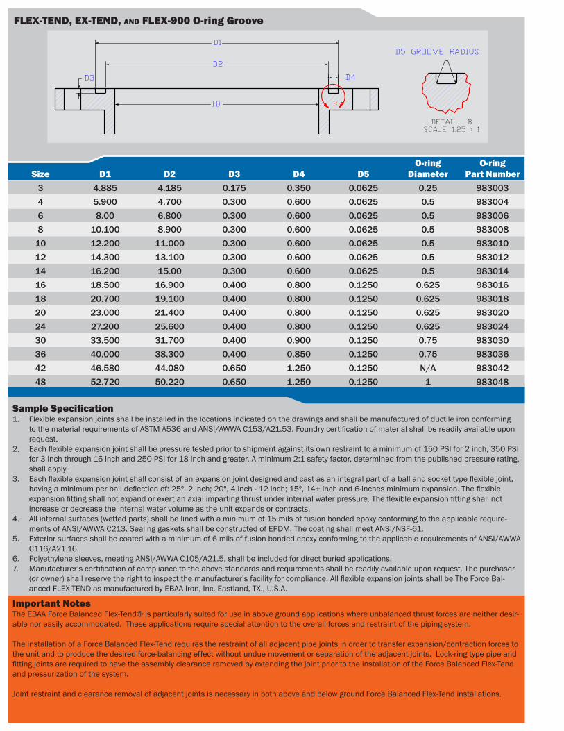
DETAIL BSCALE 1.25 : 1
D5 GROOVE RADIUS D1
D2
ID
D3 D4
B
Sample Specification1. Flexible expansion joints shall be installed in the locations indicated on the drawings and shall be manufactured of ductile iron conforming
to the material requirements of ASTM A536 and ANSI/AWWA C153/A21.53. Foundry certification of material shall be readily available upon request.
2. Each flexible expansion joint shall be pressure tested prior to shipment against its own restraint to a minimum of 150 PSI for 2 inch, 350 PSI for 3 inch through 16 inch and 250 PSI for 18 inch and greater. A minimum 2:1 safety factor, determined from the published pressure rating, shall apply.
3. Each flexible expansion joint shall consist of an expansion joint designed and cast as an integral part of a ball and socket type flexible joint, having a minimum per ball deflection of: 25º, 2 inch; 20º, 4 inch - 12 inch; 15º, 14+ inch and 6-inches minimum expansion. The flexible expansion fitting shall not expand or exert an axial imparting thrust under internal water pressure. The flexible expansion fitting shall not increase or decrease the internal water volume as the unit expands or contracts.
4. All internal surfaces (wetted parts) shall be lined with a minimum of 15 mils of fusion bonded epoxy conforming to the applicable require-ments of ANSI/AWWA C213. Sealing gaskets shall be constructed of EPDM. The coating shall meet ANSI/NSF-61.
5. Exterior surfaces shall be coated with a minimum of 6 mils of fusion bonded epoxy conforming to the applicable requirements of ANSI/AWWA C116/A21.16.
6. Polyethylene sleeves, meeting ANSI/AWWA C105/A21.5, shall be included for direct buried applications.7. Manufacturer’s certification of compliance to the above standards and requirements shall be readily available upon request. The purchaser
(or owner) shall reserve the right to inspect the manufacturer’s facility for compliance. All flexible expansion joints shall be The Force Bal-anced FLEX-TEND as manufactured by EBAA Iron, Inc. Eastland, TX., U.S.A.
Size D1 D2 D3 D4 D5O-ring
DiameterO-ring
Part Number3 4.885 4.185 0.175 0.350 0.0625 0.25 9830034 5.900 4.700 0.300 0.600 0.0625 0.5 9830046 8.00 6.800 0.300 0.600 0.0625 0.5 9830068 10.100 8.900 0.300 0.600 0.0625 0.5 983008
10 12.200 11.000 0.300 0.600 0.0625 0.5 98301012 14.300 13.100 0.300 0.600 0.0625 0.5 98301214 16.200 15.00 0.300 0.600 0.0625 0.5 98301416 18.500 16.900 0.400 0.800 0.1250 0.625 98301618 20.700 19.100 0.400 0.800 0.1250 0.625 98301820 23.000 21.400 0.400 0.800 0.1250 0.625 98302024 27.200 25.600 0.400 0.800 0.1250 0.625 98302430 33.500 31.700 0.400 0.900 0.1250 0.75 98303036 40.000 38.300 0.400 0.850 0.1250 0.75 98303642 46.580 44.080 0.650 1.250 0.1250 N/A 98304248 52.720 50.220 0.650 1.250 0.1250 1 983048
FLEX-TEND, EX-TEND, and FLEX-900 O-ring Groove
Important NotesThe EBAA Force Balanced Flex-Tend® is particularly suited for use in above ground applications where unbalanced thrust forces are neither desir-able nor easily accommodated. These applications require special attention to the overall forces and restraint of the piping system.
The installation of a Force Balanced Flex-Tend requires the restraint of all adjacent pipe joints in order to transfer expansion/contraction forces to the unit and to produce the desired force-balancing effect without undue movement or separation of the adjacent joints. Lock-ring type pipe and fitting joints are required to have the assembly clearance removed by extending the joint prior to the installation of the Force Balanced Flex-Tend and pressurization of the system.
Joint restraint and clearance removal of adjacent joints is necessary in both above and below ground Force Balanced Flex-Tend installations.

Expansion / Contraction Joint
Ball Joint
Ball Joint
Laying Length (L)
Center Line (CL)
Total Length (TL)
Center Line (CL)
Offset(S)
Laying Length (L)
OutsideDiameter(OD)
Flange by Flange Mechanical Joint by Mechanical Joint
Flange by Flange Mechanical Joint by Mechanical JointNominalPipe Size OD D* E** CL S
SeriesNumber L
Weight(lbs)
SeriesNumber L TL
Weight(lbs)
2 6.20 25° 6.5 44.7 19.7 4402F20B 50.5 (±3) 48.4 ~ ~ ~ ~
3 10.2 20° 8 42.5 15.9 4403F20B 53.7 (±4) 210 ~ ~ ~ ~
4 10.2 20° 8 42.5 15.9 4404F20B 53.8 (±4) 167 4404M20B 49.7 (±4) 54.7 (±4) 206
6 12.3 20° 8 44.0 16.5 4406F20B 56.8 (±4) 275 4406M20B 52.4 (±4) 57.4 (±4) 316
8 14.9 20° 8 48.1 17.8 4408F20B 62.9 (±4) 377 4408M20B 57.8 (±4) 62.8 (±4) 496
10 18.1 20° 8 50.6 18.7 4410F20B 67.0 (±4) 594 4410M20B 63.0 (±4) 68.0 (±4) 635
12 20.8 20° 8 52.9 19.4 4412F20B 72.0 (±4) 786 4412M20B 66.3 (±4) 71.3 (±4) 880
14 26.5 15° 10 65.3 17.5 4414F20B 93.5 (±5) 1,846 4414M20B 84.6 (±5) 91.5 (±5) 1768
16 26.5 15° 10 65.3 17.5 4416F20B 91.5 (±5) 1,779 4416M20B 86.0 (±5) 93.0 (±5) 1709
18 29.8 15° 10 69.5 18.6 4418F20B 95.4 (±5) 2,573 4418M20B 87.6 (±5) 94.6 (±5) 2431
20 33.1 15° 12 75.0 20.1 4420F20B 98.3 (±6) 2,885 4420M20B 95.7 (±6) 102.7 (±6) 2897
24 39.1 15° 12 81.7 20.6 4424F20B 110.9 (±6) 4,394 4424M20B 109.0 (±6) 116.0 (±6) 4340
30 47.8 15° 16 103.5 28.9 4430F20B 136.8 (±8) 9,224 ~ ~ ~ ~
36 59.3 15° 16 105.9 29.5 4436F20B 140.1 (±8) 11,158 ~ ~ ~ ~
NOTE: Dimensions are in inches, and are subject to change without notice.End connection combinations available (14 inch - 24 inch).
*Deflection Angle is per ball.**Maximum expansion.
FLEX-TEND Force Balanced Submittal DrawingE
BA
A IR
ONE
BA
A I
RO
N
Applicable• Potable or Non-Potable Water (no solids
or debris)• Fire Service Mains• Fire Sprinkler Systems• Chilled or Heated Water Systems (HVAC)• Above or Below Ground
Not Applicable• Water with solids, such as storm or
waste-sewage (use standard FLEX-TEND)• Petroleum liquids or gas• Steam
Additional Applications
Force Balanced FLEX-TENDS
Flexible expansion joints have been used for many years with great success. They protect pipelines while crossing shear plains such as seismic faults or protection of a structure’s pipeline system from either a seismic event or from gradual soil subsidence. They have however one drawback; they generate an axial imparting force while under pressure. While this imparting force or thrust is easy to accommodate with a pipeline that stretches across a rural landscape, it becomes cumbersome and costly in municipal settings to engineer and build a restraint system that can isolate these imparting thrusts without interfering with the purpose of the unit, which is to protect the pipeline from sudden or gradual movement generated by the environment and not the imparting thrust.
The Force Balanced FLEX-TEND® Flexible Expansion Joint can accommodate pressure induced thrust forces by utilizing an additional water chamber piston that acts in the equal and opposite direction of the imparting thrust and hence neutralizes the thrust forces. This neutralization of the pressure thrust allows designers to use flexible expansion joints in applications were bulky cumbersome thrust blocks or other means of force restricting devices are not applicable. Finally, a flexible expansion joint can now be placed into a system as easily as putting in a spool piece of pipe, rather than having to either dig out large areas for a thrust retaining walls and blocks, or by engineering costly lateral bracing that must be supported by structures that may not have been designed to take these forces.
Another concern is the addition of a needed flexible expansion joint to protect a pipeline system that serves a structure or uses a structure to make a crossing of some type. Most structures, such as water storage tanks, base isolated buildings, and bridges, were not designed to restrain the imparting thrust of a typical expansion joint, thus adding considerable cost in developing a restraint that can isolate the thrust without hampering the unit’s ability to move as needed to protect the pipeline. The Force Balanced FLEX-TEND solves all these problems while giving the designer and owner the security of knowing his pipeline systems were protected from shear.
Additionally and just as important, as the unit expands and contracts to accommodate the needs of the pipeline system, the volume inside the unit never changes unlike traditional expansion joints. This is
exceptionally important when protecting base isolated structures such as buildings. A normal expansion unit will increase its volume of water during the expansion stroke, and then reduce that volume during the contraction stroke, in essence creating a ‘pumping’ action drawing water through the distribution pipe system, through the back flow preventers and forcing it into the structure, possibly causing water damage.
Municipalities are also experiencing a common theme in their maintenance and expansion programs for their water and wastewater needs: Congestion. The shear amount of buried utilities is already staggering and the future only holds more as cities grow and not only add more buried utilities but increase the size of the existing water and wastewater pipeline systems. In this existing and anticipated congestion, the Force Balanced FLEX-TEND Flexible Expansion Joint can not only protect pipeline systems from movement as any other flexible expansion joint, it can do so with a smaller and overall less expensive footprint, allowing room for the existing or future utilities that may one day join it.
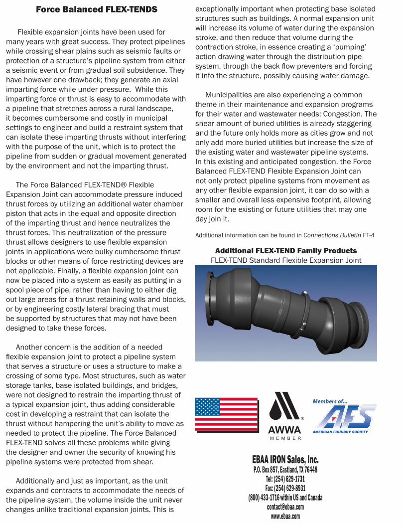
Additional information can be found in Connections Bulletin FT-4
Additional FLEX-TEND Family ProductsFLEX-TEND Standard Flexible Expansion Joint