
Force and moment analysis of stacked counter rotating eccentric mass tree shaker energy-wheel
77
Force and moment analysis of stacked counter rotating eccentric mass tree shaker energy-wheel system by Lloyd Dale Snell A thesis submitted to the graduate faculty in partial fulfillment of the requirements for the degree of MASTER OF SCIENCE Major: Agricultural Engineering Program of Study Committee: Stuart J. Birrell, Major Professor Steven Mickelson Brian Steward Iowa State University Ames, Iowa 2008 Copyright © Lloyd Dale Snell, 2008. All rights reserved
Transcript of Force and moment analysis of stacked counter rotating eccentric mass tree shaker energy-wheel

Force and moment analysis of stacked counter rotating
eccentric mass tree shaker energy-wheel system
by
Lloyd Dale Snell
A thesis submitted to the graduate faculty
in partial fulfillment of the requirements for the degree of
MASTER OF SCIENCE
Major: Agricultural Engineering
Program of Study Committee:
Stuart J. Birrell, Major Professor
Steven Mickelson
Brian Steward
Iowa State University
Ames, Iowa
2008
Copyright © Lloyd Dale Snell, 2008. All rights reserved

ii
TABLE OF CONTENTS
LIST OF FIGURES ............................................................................................................................ IV
LIST OF TABLES ............................................................................................................................ VII
ABSTRACT .................................................................................................................................... VIII
CHAPTER 1. INTRODUCTION ....................................................................................................... 1
CHAPTER 2. TYPICAL TREE SHAKER MECHANISM .......................................................... 11
TYPICAL MECHANICAL COMPONENTS .............................................................................. 11
ENERGY-WHEELS .................................................................................................................... 13
PADS, SLINGS, AND LUBRICATION ..................................................................................... 16
OBJECTIVES ............................................................................................................................... 21
CHAPTER 3. ENERGY-WHEEL FORCES .................................................................................. 22
VARIABLE DEFINITIONS ........................................................................................................ 22
PLANER FORCES ....................................................................................................................... 23
MOMENTS & FORCES .............................................................................................................. 37
SYSTEM EFFICIENCY .............................................................................................................. 47
DISCUSSION OF FINDINGS ..................................................................................................... 51
CONCLUSIONS ................................................................................................................................. 54
FUTURE RESEARCH ................................................................................................................. 55
ACKNOWLEDGEMENT ............................................................................................................ 55

iii
REFERENCES ................................................................................................................................... 56
APPENDIX A. STAR PLOTS THEORETICAL VS. 66% Y-AXIS EFFICIENCY .................. 59
APPENDIX B. THINNING PLOTS THEORETICAL VS. 66% Y-AXIS EFFICIENCY ......... 60
APPENDIX C. SPIRAL ORBIT PLOTS THEORETICAL VS. 66% Y-AXIS EFFICIENCY 61
APPENDIX D. TRIANGLE PLOTS THEORETICAL VS. 66% Y-AXIS EFFICIENCY ........ 62
APPENDIX E. CRYSTAL BALL SAMPLE CODE FOR TREE 1 AND 2 ................................. 63

iv
LIST OF FIGURES
Figure 1. OMC Shaker clamped to the trunk of an almond tree............................................................ 1
Figure 2. Tree trunk damage, barking, due to shaker head impact with the tree. .................................. 3
Figure 3. Simulation results for 25 years lifetime meat loss due to a 1% shaker
damage/year, 95% confidence interval. ................................................................................... 9
Figure 4. Simulation results for 25 years lifetime production loss and gross production
potential, kg/hectare. ................................................................................................................ 9
Figure 5. Lifetime production gains, meat pounds, due to 0.5% reduction in shaker
damage and increased orchard life span by one year (26 years). ........................................... 10
Figure 6. Orchard Machinery Corporation (OMC) side mount tree shaker with Magnum
head. ....................................................................................................................................... 11
Figure 7. Typical stacked eccentric mass counter rotating energy-wheels system. The v-
belt wedge drives the upper sheave, loops around an idler sheave and drives the
lower sheave with the belt back, thus producing counter rotation. Weights are
bolted to eccentrics to increase force. .................................................................................... 13
Figure 8. Used FMC three wheel, mono-boom tree shaker. ................................................................ 14
Figure 9. Westec patented, two hydraulic motors, three eccentric mass energy-wheels.
Two wheels are counter rotating and the third is independent (Westerguard,
1983). ..................................................................................................................................... 15
Figure 10. Tree shaker pad system with shell-filled air-cooled pad, inner positioning
sling, and outer slip sling. ...................................................................................................... 17
Figure 11. Reference coordinate system relative to the slings and pads. ............................................ 19
Figure 12. Reference coordinate system relative to tree. .................................................................... 20

v
Figure 13. Orchard Machinery Corporation (OMC) advertised shaker head energy
patterns. .................................................................................................................................. 26
Figure 14. Modified star pattern plot using Equation 12 and values from Table 4. ............................ 28
Figure 15. Star pattern plot using Equation 12 and values from Table 4 ............................................ 29
Figure 16. Thinning pattern plot using Equation 12 and values from Table 4. ................................... 29
Figure 17. Spiral Orbit pattern plot using Equation 12 and values from Table 4. ............................... 30
Figure 18. Triangle pattern plot using Equation 12 and values from Table 4. .................................... 30
Figure 19. Reaction forces ................................................................................................................... 32
Figure 20. Plots of measured displacement for almond trees (Abedel-Fattah, 2003) ......................... 33
Figure 21. Dual Triangle pattern results in a single applied force to the tree when
contained in a common structure. .......................................................................................... 35
Figure 22. Linear shaker pattern .......................................................................................................... 36
Figure 23 Section of a typical energy-wheel assembly. ...................................................................... 38
Figure 24 Two-dimensional plot, force and moment maxima and minima ........................................ 40
Figure 25. Bidirectional planer system, force and moment plot .......................................................... 40
Figure 26. Force and Moment, at time t0 ............................................................................................. 41
Figure 27. Force and Moment, at time t1 ............................................................................................. 42
Figure 28. Force and Moment, at time t2t2........................................................................................... 43
Figure 29. Force and Moment, at time t3 ............................................................................................. 44
Figure 30. Moment magnitude and direction using local reference frame. ......................................... 45
Figure 31. Peak to peak with negative moment ................................................................................... 46
Figure 32. Planer plot of moment and force magnitude for the modified star shaker
pattern, 100% y-axis displacement efficiency. ...................................................................... 48
Figure 33. Plot of moment and force magnitude for the modified star shaker pattern,
100% y-axis displacement efficiency. ................................................................................... 49

vi
Figure 34. Planer plot of moment and force magnitude for the modified star shaker
pattern, 66% y-axis displacement efficiency. ........................................................................ 50
Figure 35. Plot of moment and force magnitude for the modified star shaker pattern, 66%
y-axis displacement efficiency. .............................................................................................. 50
Figure 36. Modified Star, 66.% y-axis efficiency, moment magnitude, and direction ........................ 51
Figure 37. Tree shaker force regenerator............................................................................................. 52

vii
LIST OF TABLES
Table 1. Bearing acres and value of crops harvested by mechanical tree shaking (after
United States Department of Agriculture, 2007) ..................................................................... 2
Table 2. Typical tree density per hectare and total tree shaken per year ............................................... 2
Table 3. Almond Board of California historical data of almond production, kg/hectare
(Almond Board of California, 2007). ...................................................................................... 7
Table 4. Sheave diameters and eccentric wheel weights used to generate theoretical
shaker patterns. ...................................................................................................................... 28
viii
ABSTRACT
The tree shaker is a high throughput hydro-mechanical systems used in nut and fruit harvest.
Many commercial tree shakers use stacked counter rotating eccentric mass energy-wheels to dislodge
the crop from the tree by attaching and shaking the trunk. Tree shakers are known to cause tree trunk
damage by approach impact, barking, and bruising of the tree trunk. Tree trunk damage, catastrophic
or accumulative, could account for a 4% lifetime production loss, 1408 kg/hectare.
The energy-wheels are commonly known to create planer pulse forces. The pulse is created
by the rotation of eccentric mass about a fixed common shaft. The frequency and magnitude of the
force is determined by the weight, angular velocity, and center of gravity location of each energy
wheel. The industry has developed pads and slings to conform to the tree trunk and transmit the force
while minimizing the potential for trunk damage. Lubrication of the slings reduces the coefficient of
friction and allows unwanted force dissipation. Lubrication of the slings reduce the transfer of non-
normal forces.
This research discloses the presence of moments and extends the planer equations to allow
analysis of moment magnitudes and the introduction of planer losses in the y-axis. Moments and
planer forces are always present in stacked counter rotating eccentric mass energy-wheel systems.
Moments are non-normal forces and are dissipated in the slings, pads, shaker head suspension system.
Moments and y-axis losses reduce the efficiency of the system and require additional hardware and
systems to control adverse effects on the tree trunk.
Understanding the magnitude of moments will allow development of new systems to extend
the application of mechanical shakers to other crops and applications.

1
CHAPTER 1. INTRODUCTION
In the hot dry heat of late
summer, a tree shaker positioned
below the dusty green tree canopies
of an almond orchard in the Central
Valley of California prowls toward a
tree (Figure 1). It is guided quickly
to a stop by the operator, its shaker
head positioned around the tree. The
clamp cylinder is energized,
compressing and conforming pads around the trunk while subtly twisting the shaker head and tree
trunk into an uncomfortable alignment. The hydraulic system then automatically sequences from the
clamping circuit to the shaking circuit, launching the shaker head into a vigorous shaking pattern for
approximately three seconds. The crop rains down in a cloud of dust and debris, unburdening the tree
branches and allowing them to spring in relief toward the sky. During these three seconds, the soil
cracks at the base of the tree, resonating the vibration through the orchard floor. When the shake lever
is released, the hydraulic system screeches under dynamic braking and the shaker head brakes hard to
a stop. The shaker head is then unclamped, and the engine roars to maximum speed, accelerating the
clamp arm open. The tree shaker accelerates away from the tree and the harvest of the tree is
complete. This process is then repeated every 15-30 seconds depending on the crop, tree spacing,
planting pattern, shaker type, and operator.
The modern tree shaker harvests a diversity of crops including almonds, walnuts, pecans,
pistachios, and cherries. The United States Department of Agriculture (United State Department of
Figure 1. OMC Shaker clamped to the trunk of an
almond tree.

2
Agriculture, 2007) reports that the value of mechanically shaken crops harvested annually is $3.95
billion (Table 1) and the calculated number of trees shaken in the process is 95 million (Table 2).
Table 1. Bearing acres and value of crops harvested by mechanical tree shaking (after United
States Department of Agriculture, 2007)
United States - 2007 Crop Statistics
Crop Bearing Acreage
Yield per hectare Production Price per kg Value
1000 hectare kg 1,000 kg Dollars 1,000 dollars
Almonds1 (in-shell) 235 4,416 1,100,000 3.48 2,127,375 Walnuts (in-shell) 85 3,346 295,000 2.56 754,000 Pistachios (in-shell) 42 4,120 189,000 2.98 561,600 Pecans (in-shell) 943 1,8722 175,000 2.49 434,725 Cherries 14 8,182 113,000 0.60 67,923 Totals 370
1,872,000
3,945,623
1 Yield based on in-shell basis. Shelling ratio for 2007 is 0.573. 2 Based on data from Historical Background of Pecan Plantings in the Western Region, (Herrera, 2000). 3 Calculated: Bearing Acreage = Production / Yield per hectare.
Table 2. Typical tree density per hectare and total tree shaken per year
United States - Tree density and number of trees shaken per year
Crop Trees per hectare Trees shaken6
Min. Max Average Total
Almonds1 185 299 242 56,840,000
Walnuts2 79 292 185 16,125,000
Pistachios3 272 358 316 13,387,500
Pecans4 25 74 49 4,615,569
Cherries5 247 383 316 4,424,250
Totals
95,392,3196 1 (Freeman, Viveros, Klonsky, & De Moura, 2008) 2 (Walnut Marketing Board, 2008) 3 (Mosz, 2002) 4 (Bell, 2001) 5 (Moser Fruit Tree Sales, Inc.) 6 Tree shaken = production hectare (Table 1) / Average trees per hectare

3
The mechanical tree-shaker, as seen in Figure 1; is a hydro-mechanical system that has
evolved into a reliable and invaluable harvesting technology since the 1960s. Without the utilization
of mechanical harvesting, the successful large-scale cultivation of many nut and fruit crops would be
economically infeasible. The advantages of mechanical tree shakers include minimized labor cost,
high crop removal, crop flexibility, and high throughput. The disadvantages of mechanical tree
shakers include trunk or limb damage, water stress, and root zone disruption. Trunk and limb damage
are caused by the interaction of the mechanical tree shaker and the tree’s biology. Trunk or limb
damage at the clamp zone is one of the most common causes of orchard asset losses due to
mechanical shaking. This damage is defined as “barking,” and is shown in Figure 2. Barking can be
either an open tear or bruising at the cambium layer which damages the xylem and phloem cells
responsible for nutrient transfer. To reduce such damage, pre-harvest cultural practices induce water
stress by shutting off irrigation. Water stress causes the moisture in the tree to be drawn down from
the xylem and phloem cells, forcing the bark to draw up tight around the tree. When the bark is tight
and dry, there is less chance of barking.
Figure 2. Tree trunk damage, barking, due to shaker head
impact with the tree.

4
However, during the harvesting process operator error due to excessive speed, fatigue, or lack
of training, can impact the shaker head with the tree trunk which is a primary cause of an open
wound. An open wound requires immediate attention to prevent the loss of a tree asset. If unattended,
the wound becomes the entrance point for disease, a barrier for nutrition flow, a source of canker
development, and the cause of a redirection of energy that would otherwise be used for crop
production in subsequent years. Barking also includes less visible damage resembling bruising rather
than an open wound. A severely bruised trunk will feel soft to the touch with a definite separation
from the trunk. Milder damage also includes discoloration of the bark after shaking. Bruising also
diverts crop production energy toward healing and survival. Trunk damage is most often caused by
the use of excessive or insufficient clamping force, improper clamp angle adjustment, insufficient
irrigation cut-off time, worn shaker hardware, insufficient pad lubrication, improper pads, and
operator inexperience. To reduce operator error, recent efforts have focused on introducing computer
control of the shaker head extension, auto clamping and shake sequence (Mayo, 2002).
Tree shaking can also result in cumulative damage due to repeated localized biological
damage resulting from clamping and force transfer during the shaking process. Growers have
developed cultural practices that alternate the clamping direction each time a shaking operation is
performed, to minimize this localized damage. Cumulative damage is hard to measure on a year-to-
year basis, as crop yields are affected by weather, pests, fertilizer, pruning, pollination, and many
other cultural practices. Often, the existence of long-term damage is evident only when the tree or
limb is no longer productive.
Many scientific studies and patents have searched for solutions to minimize production losses
due to tree damage at the clamping zone (Compton, 1990a; Ferrari and Evans, 2002; McCrill, 1992;
Hill, 1997; Blue Diamond Growers, 2008). The main challenges at the clamping zone are conforming
the pads firmly around irregular trunk shapes, firmly gripping during shaking, and discharging
excessive heat that builds up during the shaking process. If not dispersed, intense heat can cause pads

5
and slings to degrade, locally abrade, or split. In the early shaker designs, intense heat could even
cause the hollow shell-filled pillow pads to explode. Most of these adverse effects have been
mitigated by improvements in design of the shaker slings, pads, and lubrication systems, materials,
and shaking processes.
Early shaker heads and transportation systems were also susceptible to high cycle fatigue
failures. Shaker head evolution over time included, the utilization of thicker sections, higher strength
materials, and localized structural improvements to counter the destructive effects on tree shakers.
Improvements resulted in more robust and reliable shaker heads, which were larger and heavier with
each production generation. With the additional mass of the shaker head structure, the hydro-
mechanical stacked eccentric mass energy-wheels, which is the most successful low-cost vibration
system, also became larger to provide greater dynamic forces to overcome the greater inertia forces of
the shaker head and tree. This forced increases in both the hydraulic and engine power requirements.
In the end, this increase in size to prevent high cycle fatigue required the pad and slings to dissipate
even more heat. The new structure in one area, often only transferred the structural failure to another
location and the cycle of larger and more robust shaker heads continued.
Mechanical tree harvesting processes can and do cause direct, and indirect damage to the tree.
Indirect damage is the stress occurred when the orchard is water stressed prior to harvest in order to
prevent trunk damage during shaking. Direct damage is damage caused by the shaker during any
phase of the tree shaking process. This damage often results in production losses due to nutrition
disruption to a limb or tree death. Almond orchards are capital intensive and take five years to enter
economical production. Generally, the prime productive life is approximately 20-25 years (Almond
Board of California, 2008) and any damage that leads to tree damage or loss in the final 5-8 years is
rarely replaced. The success of replanting trees is also limited by different cultural requirements of
new versus established trees, such as competition for light. Mature trees expand into voided areas,
increase in production, while new trees will be shaded more, and thus develop more slowly.

6
With such industry focus on the preventing of tree damage, how significant is the production
loss if 1% tree damage due to mechanical shaking is acceptable. The 1% tree damage per year was
determined as a starting point based on personnel experience, and discussions with farmers like Don
Davis, Manager of Alina Farms in McFarland, California, (Davis, 2008). In these discussions the
question, “Is one tree in a hundred damaged by the tree shaker?” or, “Do two or more trees in a
hundred have partial damage sufficient enough to equal 1% damage due to tree shaking?” The answer
is probably. The industry has an understanding that shaking can be damaging. In fact, tree shaking in
the almond industry can be very damaging if the mechanical quality of the equipment and the
operator skill are not sufficient to prevent damage. Currently, no data identifies tree shaker damage,
type, and magnitude, for seasonal or long-term cumulative damage. The magnitude of loss due to
mechanical tree shaking was estimated using a Monte Carlo simulation using the following
constraints.
1. Third and fourth leaf production are not included.
2. Full production of an almond tree begins at fifth leaf.
3. Total productive life of the orchard is 25 years.
4. A 1%.probability of tree damaged is assumed per shaking event.
5. The model assumes only a single shaking event per year. This shaking event is for
the removal of the crop.
6. A damaged tree is assumed as a 100% loss. No weighting is applied to account for
barking or bruising as the cause of production loss.
7. Lost trees are replanted and are not shaken or used in production calculations until
the fifth leaf.
8. Assumptions are for almond tree production was developed using the historical
production mean and standard deviation production, kg/hectare (Almond Board of

7
California, 2007). These values were divided by the trees/hectare to develop a
normal distribution for individual tree production.
Table 3. Almond Board of California historical data of
almond production, kg/hectare (Almond Board of
California, 2007).
Year
Almond Production, kg/hectare Year
Almond Production, kg/hectare
1987 1771 1997 1927
1988 1580 1998 1266
1989 1334 1999 1927
1990 1804 2000 1546
1991 1356 2001 1759
1992 1535 2002 2241
1993 1334 2003 2118
1994 1905 2004 1972
1995 992 2005 1771
1996 1334 2006 2140
Average, trees/hectare 242
Average, production/hectare 1681
StDev, production/hectare 338
Average, production/tree 6.94
StDev, production/tree 1.40
9. Crystal Ball Softwarei was utilized to statistically simulate the theoretical effects of
shaker damage over the life of an orchard, Appendix 1.
10. Two hundred and forty two trees are used as the average planting density (Table 2).
This simulation has a column for each tree. Each tree is check each for:
a. Age, is the age of the tree based on the previous year. If the tree is damage in
the orchard lifetime the age of the tree is reset to zero the following year the
damage event. It often takes a year to define the damaged tree, remove, and
prepare to replant a new tree.

8
b. Damage logic, is a random distribution were zero is no damage and one is
damage. Damage can only occur if the tree is greater than or equal to five
years old.
c. Harvest logic, set the variable to one if the tree is greater than or equal to
five years old and zero otherwise.
d. Gross harvest, is the value randomly generated from a normal distribution
using the production data mean and standard deviation per tree (Table 3).
e. Net harvest, is gross harvest multiplied by harvest logic to determine the
trees annual production.
f. Gross annual production is the sum of the gross harvest values.
g. Gross net annual production is the sum of the tree net harvest values.
h. Gross orchard production is the sum of gross annual production.
i. Gross net production is the sum of the gross net annual production.
11. Number of trials is set to 5000.
The Monte Carlo simulation show that 1% shaker damage results 1408 kg/hectare lifetime
production loss based on a 95% confidence interval (Figure 3). When compared to the lifetime
production without loss, damage due to tree shaking results in a lifetime production loss of 4%
(Figure 4). If the cost due to mechanical harvest could be eliminated the gross value of delivered
product would increase annually $85 million. If a reduction in tree damage (0.5%) along with
extending the lifetime production by one year (26 years) an orchard would yield a 107% (2324
kg/hectare) over an orchard with the 1% damage rate (Figure 5).

9
Figure 3. Simulation results for 25 years lifetime meat loss due to a 1% shaker damage/year,
95% confidence interval.
Figure 4. Simulation results for 25 years lifetime production loss and gross production
potential, kg/hectare.

10
Figure 5. Lifetime production gains, meat pounds, due to 0.5% reduction in shaker damage
and increased orchard life span by one year (26 years).
It could be argued that the contemporary tree shaker design is a brute force mechanical
system that is significantly more powerful than needed to dislodge the crop from the tree, and the cost
of this power, could be 4% total production loss over the lifetime of an orchard. Although orchard
productivity is adversely affected by damage caused by mechanical tree harvesting, the tree shaker
remains the most productive harvesting method for many nut and fruit crops because the benefits
greatly outweigh the costs.

11
CHAPTER 2. TYPICAL TREE SHAKER MECHANISM
TYPICAL MECHANICAL COMPONENTS
The Magnum Shaker head, manufactured by the Orchard Machinery Corporation (Orchard
Machinery Corporation, 2007), is typical example of the nut and fruit harvesting industry (Figure 1
and Figure 6). The current tree shaker platforms consist of a hollow welded steel case structure
(Figure 6 - 01) containing the drive sheave, drive belt, two or more eccentric rotating masses
commonly referred to as energy-wheels, hydraulic clamp cylinder(s), and hose routings. The
hydraulic drive (Figure 6 - 02) motor mounts to the top of the case structure and is connected to the
drive pulley. The tree trunk clamping super structure is an integral part of the case structure housing
(Figure 6 - 03). A pivot pin (Figure 6 - 04) at the rear of the case structure attaches the clamping arm
01
07
0605
09,10
02
03
04
08
11
Figure 6. Orchard Machinery Corporation (OMC) side mount tree shaker with Magnum head.
12
(Figure 6 - 11). Opposing the case structure is the clamp arm. The clamping arm applies a
compressive force during the shaking process when hydraulic oil causes the hydraulic cylinder to
retract (Figure 6 - 05) and pivots the clamp arm about the pivot pin. A sling set (Figure 6 - 06) and
pads (Figure 6 - 07) are mounted on the clamp arm and the case structure. The shaker head is
suspended from a hanger frame (Figure 6 - 08) by a series of rubber isolators (Figure 6 - 09), C-bars
(Figure 6 - 10), or chains (not shown), allowing the shaker head to be lifted, tilted, and rolled similar
to the motions of the human shoulder, wrist, and forearm, respectively. Proper clamp angle is
important to prevent adverse preload on the tree or the shaker structure. Improper clamp angle will
often cause barking, and will be discussed more thoroughly in Chapter 2. Both the clamping arm and
case structure contain a set of slings and pads.
The shaker-head’s current assembly weight of approximately 900-kg has continually
increased since its initial development in the mid-1960s. As the shaking head mass increased, the
required energy-wheel mass needed to create an equivalent shaking force also increased. As will be
further explained in the mathematical modeling section, this increased the moments that are
developed, and therefore increased the fatigue induced by torque on the shaker housing, clamp arm
and other related components.

13
ENERGY-WHEELS
The general agribusiness professional typically has two common beliefs about the stacked
rotating eccentric mass energy-wheel system. The first belief is that when the mass force vectors
align, there is an impulse. Second, when the mass force vectors are opposed, nothing happens. In
other words, the belief is that the stacked rotating eccentric mass energy-wheel system is planer and
all force couples cancel.
The shaker head creates the shaking force with two stacked counter rotating eccentric mass
energy-wheels (Figure 7 - 12, 13). These two components are typically flame cut plates with a
cylinder of steel welded to one side. The assembly is then turned, creating the bearing bores, belt
grooves, and faced to provide a flat surface for mount addition weight. Two bearing mounts in
Figure 7. Typical stacked eccentric mass counter rotating energy-wheels system. The v-belt
wedge drives the upper sheave, loops around an idler sheave and drives the lower sheave with
the belt back, thus producing counter rotation. Weights are bolted to eccentrics to increase
force.

14
each energy-wheel and a connecting shaft is pulled into the bearing sets of each energy-wheel after
the assembly is position inside the case. The energy-wheels are stacked about the midpoint of the
shaft and in the final assembly carefully locked to the upper and lower plate, and compressed between
the upper and lower plate of the shaker head case. The flame cut eccentric mass plates are positioned
between the head to allow the bolting on of additional weights. The additional weights bolted on
(Figure 7 - 15, 16), increase the system’s maximum peak force and vary the shaking pattern. The
energy-wheels may have an integral drive belt (Figure 7 - 14), grooves, or a sheave (not shown)
mounted to the energy-wheel. Changing the drive and driven sheaves ratios, changes the shake
pattern and peak forces. The energy-wheels are typically not physically timed to the case. In the event
of belt slippage, the peak forces will shift relative to prior angular orientation ( ). The resultant forces
Energy Wheel
Energy Wheel
Figure 8. Used FMC three wheel, mono-boom tree shaker.

15
generated by the energy-wheels are transferred to the shaft at the bearings contacts and then to the
housing.
Typically, the energy-wheels
rotate in opposing directions, creating
amplification spikes in a pattern
determined by the mass and angular
velocity. Although counter-rotating
energy-wheels are most common,
successful shaking results are also
obtainable by energy-wheels rotating in
the same direction at different angular
velocities. Michelson (1998) for instance,
suggests a method of creating a shaker
pattern using two eccentric masses
rotating in the same direction. Other
variations include tree shaker heads
previously manufactured by Farm
Machinery Corporation (FMC), which
have uniquely mounted energy-wheels
that are unidirectional and mounted on
individual shafts, in similar but opposing
clamp arms that pivot about a pin located
at the rear of the shaker head. A hydraulic
cylinder provides closing and the
Figure 9. Westec patented, two hydraulic motors,
three eccentric mass energy-wheels. Two wheels are
counter rotating and the third is independent
(Westerguard, 1983).

16
necessary clamping force during the shaking process (Figure 8). Another tree shaker manufacturer,
Westec Hydraulics, introduced a third energy-wheel independently located and driven as shown on
Figure 9 (Westerguard, 1983). Although touted as revolutionary, the introduction of a third energy-
wheel merely added additional components to the summation equation of the forces, shown in Figure
9, and relocated the moment summation origin. Furthermore, as a rotating member, the force spikes
and moments still existed, and the ability to overpower the natural tree dynamics only increased.
The development of energy wheel systems and pad and sling cooling systems account for the
largest body of patents pertaining to mechanical tree shakers (Hood et al., 1979; Savage, 1981;
Zehavi and Chiel, 1995; Reynolds et al., 1997; Michelson, 1998). Recent developments continue
toward trying to time the energy-wheels on a single plane to eliminate all negative forces, (Zehavi and
Chiel, 1995; Zehavi and Chiel, 2005). The systems developed currently use timing and structural
constraints to contain the undesirable force associated rotating energy-wheel systems.
PADS, SLINGS, AND LUBRICATION
The typical tree shaker head is hydraulically clamped to the tree, engaging the outer sling to
the tree bark. The inner sling, commonly cut from rubber belting, is looped around the shaker pad,
locating the pad with respect to the shaker head and clamp arm structure (Figure 10). The outer and
inner slings provide a semi-non-rigid connection between the tree and the mechanical tree shaker. The
operator regularly lubricates the contact surfaces between the outer and inner slings with high
temperature grease, silicone, or other lubricants to reduce the coefficient of friction and prevent
excessive heat generation. During the clamping, depending on the operator and tree structure, the
slings will allow the shaker head and the tree to move into alignment. This aligning may cause the
shaker head to pitch, roll, or slide up or down on the tree trunk. Deflection of the tree also regularly
occurs during the clamping process. If the movement of the tree shaker head is large, the shaker head,

17
or possibly the entire tree shaker, should be repositioned to prevent adverse preloading of the tree
trunk.
Figure 10. Tree shaker pad system with shell-filled air-cooled pad, inner positioning sling, and
outer slip sling.
Depending on the style of shaker pad and clamping pressure, various amounts of pad
deformation will occur when securing the shaker mechanism firmly to the tree. This deformation
around the trunk is important to maximize the transfer of forces to the tree. Reducing sling friction
also prevents barking by limiting the transmission of unwanted shaker head forces that are non-
normal to the clamped surface of the pad. Non-normal forces are the forces that induce slipping
between the inner and outer slings. Thermal buildup in the sling and pads represents inefficiencies in
the system that must be dissipated. The reduction and control of friction and thermal generation has

18
been the focus of many patents and lubrication strategies, (Compton, 1990a; Compton, 1990b;
Reynolds et al., 1997; Chiel and Zehavi, 1998). One current production strategy blows compressed air
through the pads to dissipate heat from the system and further form the shaker pads to the trunk
diameter (McCrill, 1992).
The sling and pad system has been sufficiently refined to generally prevent damage to many
varieties of tree. Yet there are instances where tree damage with the current pad and sling system is
too severe for mechanical tree shaking. Pinecone seed harvest is one example of a crop to which the
sling and pad system fail to prevent critical trunk damage during harvest. Instead, a hole must be
drilled through the trunk, long bolts inserted, and acorn nuts attached and tightened on both ends. A
custom shaker pad that accepts the acorn nuts allows the shaker head to clamp to the tree, preventing
damage during the shaker engagement. This extreme method allows for the mechanical harvesting of
the pinecone seed crop, (McConnell and Edwards, 1990; Srivastava et al., 1996). For some trees, the
mechanical tree harvester remains too damaging for economic gain. Other inventors propose
permanently attaching a threaded rest pad to the trunk of trees so that the forces of the tree shaker are
transmitted to the hardwood, thus preventing damage to the bark (Ferrari and Evans, 2002).
Working from a theoretical perspective, one must ask, “If lubrication of the slings is very
important to the prevention of trunk damage, what are the unwanted forces this lubrication is intended
to eliminate?” Assuming the surface interaction between the inner and outer sling is frictionless, then
only the force’s normal to the (y-z) plane are utilized (Figure 11). Continuing this assumption, one
then confronts the performance value of the remaining forces, Fy, Fz, and moments about Mx, My, and
Mz (Figure 12). Since the intent of the lubrication is to allow the inner and outer sling to slide versus
transferring force, if these forces are detrimental, then eliminating these apparently undesired forces
would 1) reduce input energy required, 2) eliminate or significantly reduce biological component
damage, and 3) reduce or eliminate economic losses due to excessive abuse to permanent tree assets.
Understanding the energy-wheel system with the existence of both axial forces and moments
will be beneficial in understanding the function of the current pads, slings, and lubrication systems.

19
Furthermore understanding the true dynamic system of the energy-wheel system will support further
developments that will expand the production capabilities of mechanical tree harvesting.
Figure 11. Reference coordinate system relative to the slings and pads.
yX
z

20
Figure 12. Reference coordinate system relative to tree.

21
OBJECTIVES
The fundamental rationale behind this work is that failure to recognize the moment forces has
prevented the industry from attaining the required understanding to design improved next-generation
tree shakers. The goal of this study was to understanding the dynamics of the energy-wheel system,
and ultimately utilizing that knowledge for the development of more efficient and effective shaking
systems that will increase the productive life of an orchard.
The specific objectives of this study were:
1. To explore the limitations of the planer model.
2. Expand the planer model to include moment magnitudes.
3. Analyze the effect force transmission losses on measured tree displacement.
This expansion of the planar model to include moments allowed a true representation of
shaker pattern in terms both planer forces and resultant moments due to coupled forces.
22
CHAPTER 3. ENERGY-WHEEL FORCES
VARIABLE DEFINITIONSii
a - Acceleration, ,
ar - Radial acceleration, ,
cgzl - Lower energy-wheel cg z-axis location, m (ft)
cgzu - Upper energy-wheel cg z-axis location, m (ft)
d - Drive pulley diameter, m (ft)
Dl
- Lower energy-wheel drive sheave diameter, m (ft)
Du
- Upper energy-wheel drive sheave diameter, m (ft)
F - Force, N (lbf)
Fl - Force matrix for lower energy-wheel, N (lbf)
Fu - Force matrix for upper energy-wheel, N (lbf)
Fs - Sum of forces, N (lbf)
g - Gravity
M - Moment, N*m (lbf*ft)
m - Mass, kg (slug)
ml - Mass, lower energy-wheel, kg (slug)
mu - Mass, upper energy-wheel, kg (slug)
N - Motor shaft input speed, rpm
r - Radial distance relative to axis of rotation, m (ft)
ru - Upper energy-wheel radial location of center of gravity, m (ft)
rl - Lower energy-wheel radial location of center of gravity, m (ft)

23
rvl - Vector to lower energy-wheel center of mass, m (ft)
rvu - Vector to upper energy-wheel center of mass, m (ft)
te - Duration of shaking sequence, sec
- Initial time, sec
ts - Time step for iteration, sec
zl - Distance from midpoint of shaft to lower energy-wheel cg location, m (ft)
zu - Distance from midpoint of shaft to upper energy-wheel cg location, m (ft)
- Phase angle, rad
ω - Angular velocity, rad/sec
- Change of rotation of input pulley, rad
ηx - Force transfer efficiency, x-axis, %
ηy - Force transfer efficiency, y-axis, %
ηz - Force transfer efficiency, z-axis, %
l - Lower Energy-wheel position, rad
u - Upper Energy-wheel position, rad
PLANER FORCES
The two-dimensional (planer) force models are regularly presented as the dynamics of the
shaker head system (Srivastava et al., 1996). In this chapter, the planer models will be presented,
expanded, and then further developed to disclose the moments along with the commonly explained
planar forces model. The tree-shaker-head reference frame is the following:
1. X-axis is normal to the pads, slings, clamp arm, and tree centerline.
2. Y-axis is parallel to the pads, slings, intersecting tree centerline, with clamp arm orientated
away from the tree shaker.

24
3. Z-axis is concentric to the trunk pointing skyward (Figure 11, relative to shaker head and
Figure 12, relative to the tree).
The forces of the stacked energy-wheel system are developed according to Newton’s second law.
(1)
Acceleration comes from the rotation of an eccentric mass about a pin. The equation for this radial
acceleration component is:
(2)
Substituting Equation 2 into Newton’s second law, Equation 3 defines the force created by the
energy-wheel and rigid body eccentric mass rotating about a fixed shaft.
(3)
The angular position of the upper and lower energy-wheels can be different based on diametrical
differences between the drive and driven sheave of each energy-wheel. The energy-wheel force
vector can be related to the input sheave by:
(4)
(5)

25
In addition, the angular velocities of the energy-wheels are related by sheave diameters of the input,
energy-wheel, and the input speed, N.
(6)
(7)
As the energy-wheels rotate, the magnitude of the x and y force components changes. Placing the
forces in a matrix format will assist in the calculation of moments.
(8)
The position of the drive pulley and the energy-wheels are dependent on time.
(9)
For analyzing the tree shaker as a planar system, the following two matrices, Equations 10 and 11,
develop the component forces for a shaker system’s upper and lower energy-wheels as a function of
the angular change of the cg location about the shaft of rotation. The negative sign in front of θ
(Equation 11) represents the counter rotation of the lower energy-wheel. Finally, the introduction of
efficiency variables ηx, ηy, and ηz represents force transmission efficiencies.
26
(10)
(11)
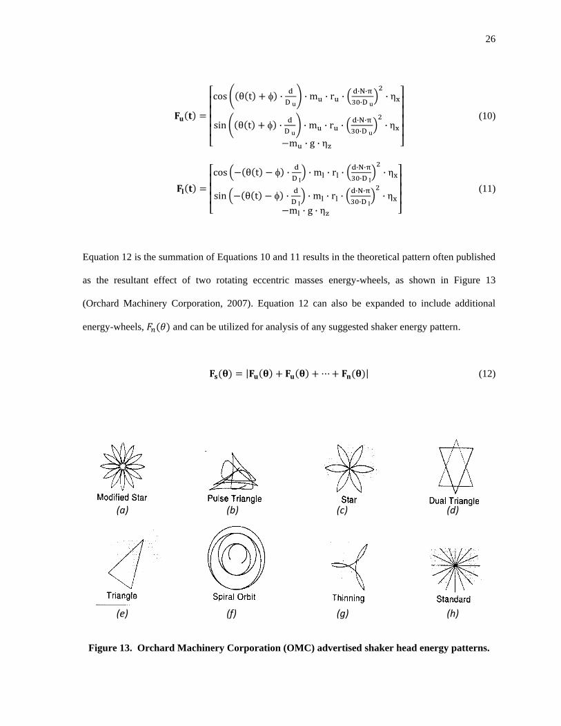
Equation 12 is the summation of Equations 10 and 11 results in the theoretical pattern often published
as the resultant effect of two rotating eccentric masses energy-wheels, as shown in Figure 13
(Orchard Machinery Corporation, 2007). Equation 12 can also be expanded to include additional
energy-wheels, and can be utilized for analysis of any suggested shaker energy pattern.
(12)
Figure 13. Orchard Machinery Corporation (OMC) advertised shaker head energy patterns.
(a) (b) (c) (d)
(e) (f) (g) (h)

27
Modifying the shaker patterns has been a successful option to create different tree shaking
dynamics. Changing the pattern shape, i.e. increasing or decreasing the number and magnitude of
impulses is a function of:
1. Sheave ratios, driver and driven
2. Adding or subtracting weight from the upper, lower, or both energy-wheels
3. Increasing or decreasing the input rpm
4. Increasing or decreasing the energy-wheel center of gravity (cg) radial position
relevant to the axis of rotation.
However, the patterns shown in Figure 13 are not all direct outputs of Equation 12. Five of
the eight patterns, the modified star (a), star (c), triangle (e), spiral orbit (f), and thinning (g), are
mathematically possible planer shaker patterns using Equation 12. A set of simple system parameters
including sheave diameters and/or the energy-wheel weights to achieve shaker patterns similar to
those published by Orchard Machinery Corporation has been defined in Table 4.
Both the pulse triangle and the dual triangle will be discussed in detail later. The standard
pattern (h) presents an interesting concept suggesting planer forces can be linearized. Furthermore,
when the force vectors are opposed, the systems are instantaneously indexed to rotate the pulse about
the truck’s z-axis (Figure 12). Timing of the energy-wheels is a special condition that is also included
in Table 4 and requires the weight, angular velocity, and energy-wheel cg location be identical. This
special and simplified concept of a linearized energy-wheel system will be used later to develop the
initial concept moments.

28
Table 4. Sheave diameters and eccentric wheel weights used to generate theoretical shaker
patterns.
Figure 14. Modified star pattern plot using Equation 12 and values from Table 4.
10000 5000 0 5000 10000
10000
5000
5000
10000
Force
x-axis force, N
y-a
xis
fo
rce,
N
Pattern Name Upper Sheave
Diameter, m
Lower Sheave
Diameter, m
Upper Energy-
Wheel Weight,
kg
Lower Energy-
Wheel Weight,
kg
Figure
Number
Modified Star 0.51 0.61 45.4 47.7 Figure 14
Star 0.46 0.61 33 47.7 Figure 15
Thinning 0.31 0.61 12.3 47.7 Figure 16
Spiral Orbit 0.25 0.61 22.7 22.7 Figure 17
Triangle 0.31 0.61 7.7 47.7 Figure 18
Linear 0.61 0.61 47.7 47.7 Figure 22

29
Figure 15. Star pattern plot using Equation 12 and values from Table 4
Figure 16. Thinning pattern plot using Equation 12 and values from Table 4.
10000 5000 0 5000 10000
10000
5000
5000
10000
Force
x-axis force, N
y-a
xis
fo
rce,
N
5000 0 5000 10000
10000
5000
5000
10000
Force
x-axis force, N
y-a
xis
fo
rce,
N

30
Figure 17. Spiral Orbit pattern plot using Equation 12 and values from Table 4.
Figure 18. Triangle pattern plot using Equation 12 and values from Table 4.
20000 10000 0 10000 20000
20000
10000
10000
20000
Force
x-axis force, N
y-a
xis
fo
rce,
N
4000 2000 0 2000 4000 6000
6000
4000
2000
2000
4000
6000
Force
x-axis force, N
y-a
xis
fo
rce,
N
31
The final three patterns Figure 13 (b, d, h) cannot be mathematically realized based on
equation 12. However, these suggested patterns will be useful in the understanding of several facts
about stacked eccentric mass energy-wheel systems, including; 1) there are extensive force transfer
losses due to the suspension system, 2), the independent rotating energy-wheels or stacked energy-
wheel systems do not result in independent reaction forces at the shaker head and tree interface, and
3) linearization of the system does not result in only normal forces. Therefore assuming cancellation
of all other forces created by stacked counter rotating energy-wheel systems is invalid.
Realistically, the Pulse Triangle shown in Figure 13 (b) reflects a triangular planer pattern
when all of the resisting and restoration forces are considered. Resistant and restoration forces are the
tree transportation hangers, hydraulic hoses, and the tree (Figure 19). The complexity of the
geometric representation is past the capabilities of Equation 12. Equation 12 will create a pattern that
is continuous between the maximum forces, and the same shape will exist between any two force
maximums. The Pulse Triangle has several force maximums and the path between each set is
different. This supports that there are additional forces acting on the system.

32
Figure 19. Reaction forces
Abdel-Fattah (2003) research provides a series of plots showing the x and y displacements of
a shaker head in a free state and attached to the tree trunk (Figure 20). The lower series of results,
shaker D4 – a, b, and c, is very representative of the modified star. As is clearly seen, the loops and
crossing patterns are reminiscent of the modified star pattern shown in Figure 14. However, the Free
Shake plot (Figure 20 (a)) does not reflect the uniformity of the mathematical plots derived from
Equation 12, but indicates that the actual system displacement must have constraints, and

33
displacement losses. The Free Shake plots shows the mechanical loss associated with the suspension
system consisting typically of three hangers and hoses connected to the hydraulic drive motor.
The center and right plots of Figure 20 demonstrate the difference between the shaker head
and tree displacement during the shaking. This represents transmission losses in the pads and slings.
The x-axis sees little loss of magnitude between the shaker head and the tree trunk displacement,
while the y-axis sees a significant displacement reduction. Abdel-Fattah (2003) found that the relative
average displacement of the y-axis to x-axis for all shakers tested was, on average, 66%. For the D4
shaker data the tree displaced 9.1mm in the x-axis and 5.9mm in the y-axis. The tree diameter is
18.1cm and the tree shaker was clamped to the tree at a height of 60cm. Remembering the slings are
lubricated to allow slippage between the tree and shaker head, the expectation is transmission of
forces parallel to the lubricated surface are reduced.
Figure 20. Plots of measured displacement for almond trees (Abedel-Fattah, 2003)
(a) (b) (c)

34
The Dual Triangle shaker head pattern shown in Figure 13 (d) indicates that two independent
triangular patterns can be created and operated as independent systems. The suggestion that there are
two independent triangular patterns as shown by the Dual-Triangle implies two sets of counter
rotating energy-wheels timed in such a manner to produce independent resultant forces. The Dual
Triangle and Standard pattern are not mathematically supported (Figure 13) and a double set stacked
counter rotating energy-wheels platform has never existed.
Figure 21 shows the plot of the initial triangular shaker pattern equals 0 degree in Equation
10 and 11. The second independent triangle is plotted by setting to 120 degree. The total forces of
two linked “independent” triangle energy systems each represented by Equation 12 can be
represented by the expanded , Equation 13.
(13)
Plotting the first and second independent energy-wheel systems simulates the advertised
shaker pattern (Figure 13). The summation of the two proposed independent energy-wheel systems,
contained in a common structure and acting on a single tree, results in the summation of vector forces
in a resultant vector force, at the tree trunk interface (Figure 21).

35
Figure 21. Dual Triangle pattern results in a single applied force to the tree when contained in
a common structure.
The final misleading energy pattern is the standard (Figure 13 (h)). The standard pattern
assumes a stacked energy system can have a bi-directional linear pulse. The pulse force then is
somehow incremented about the z-axis applying a linearized force in a different planer direction. The
common belief is that timing the eccentric mass energy-wheels system produces a bi-directional
pulse. To simulate a bi-directional pulse using Equation 12 the following constraints must exist:
1. Both the upper and lower energy-wheel must have the same mass.
2. The location of the center of gravity of the upper and lower energy-wheel must be
located the same radial distance from the common shaft.
3. The energy-wheel must be counter rotating.
10000 5000 0 5000 10000
10000
5000
5000
10000
T riangle Pat tern =0
T riangle Pat tern =120
Resultant of force vect ors
Force
x-axis force, N
y-a
xis
forc
e, N
ϕ=0, t=0
ϕ=120, t=0

36
4. The energy-wheels must have the same angular velocity.
5. Finally, the energy-wheels must be timed to the shaker head case so as to produce
only force in the x-axis, normal to the sling lubricated surface.
Figure 22 shows the results of these assumptions. The forces are normal to the shaker head and the y-
axis planer forces sum to zero. The desire of the industry to have a system with no non-normal forces
is the belief that non-normal forces are damaging and therefore must be minimized to prevent tree
damage.
Figure 22. Linear shaker pattern
10000 5000 0 5000 10000
1
0.5
0.5
1
Force
x-axis force, N
y-a
xis
forc
e, N

37
MOMENTS & FORCES
Abedel-Fattah (2003) states the following:
Most commercial trunk shakers use counter-rotating masses to deliver a
relatively high frequency (12-40Hz), small zero-to-peak displacement [5 to
20mm (0.2-0.8in)] shaking pattern to the trunk in the horizontal (x-y) plane.
Throughout the history of mechanical tree shaking force analysis has been simplified to a
planer system, the existence of a moment remains undisclosed. Visual existence of moments is easily
observed by watching a shaker head video in slow motion. The shaker head can be observed making
abrupt torsional movements, in addition to the standard planer displacement forces commonly
discussed. However, current engineering handbooks (Stout, 1999), published papers, and patents fail
to introduce the moments that exist during the rotation of two stacked eccentric masses energy-wheel
system. Believing the system is planar, inventors such as Zehavi and Chiel (1995) pursue both simple
and complex methods of the timing of energy-wheels, believing that timing will eliminate all
unwanted forces. This is a very common, if not universal belief, that the typical stacked counter
rotating eccentric mass energy-wheel system output forces that simply result in the amplification and
cancellation of planer forces.
The stacked counter rotating eccentric mass energy-wheel system transfers rotational energy
into planer forces and moments. A moment exists when a force act upon a lever and even though it
appears the stacked shaker head system has no lever, it does, two in fact. The lever in the stacked
energy-wheel system is the vertical distance from the system origin to midpoint between each energy
wheel bearing set, denoted as zu and zl in Figure 23. Although the lever is relatively short, the force
applied is large and results in a significant moment. This moment is large enough to cause the shaker
head to be seen visually rotating during the shaking process.

38
Using the established variables for the Modified Star pattern Table 4, the upper and lower energy-
wheels have a calculated radial force of 4092 and 5581 N respectively. With a lever arm of 4 cm the
resultant moment would be 387 N m. Using a similar analysis as the planer forces, one can easily
understand that the moment maximum is when the eccentric masses are opposing and the minimum is
when the eccentric energy-wheels are aligned. The cross product of the lever arm and the force matrix
is used to analysis the moment magnitude, Equation 14. The lever arm ru and rl provide the angular
orientation as a function of time and vertical position of energy-wheel contact point (Equation 15 and
Equation 16). The applied forces are determined from previously developed equations for the planer
system, Equations 10 and 11, and are substituted into Equation 14, yielding Equation 17.
ru
rl
Figure 23 Section of a typical energy-wheel assembly.

39
.
(14)
(15)
(16)
(17)
A simple initial model representing the planer bidirectional system previously discussed,
where the energy-wheels had the same mass, angular velocity, vertical lever arm distance, and cg
location, allows for a better understanding of the relationship between forces and moments. In this
idealized case, the weight of the energy-wheels is negated which will allow the moments and forces
to cycle from zero to a maximum. Review of the planer plots shown in Figure 22, simply indicate that
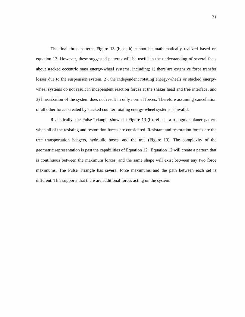
the resultant forces are bidirectional and linear. The two dimensional plot of Figure 24 provides a
simple presentation of the true relationship between the planer force and the moment. As the planer
force reaches a maximum, when the force vectors of the eccentric mass energy-wheels cross, the
moment is zero. The maximum of the moment is when the vector sum of the planer forces is zero.
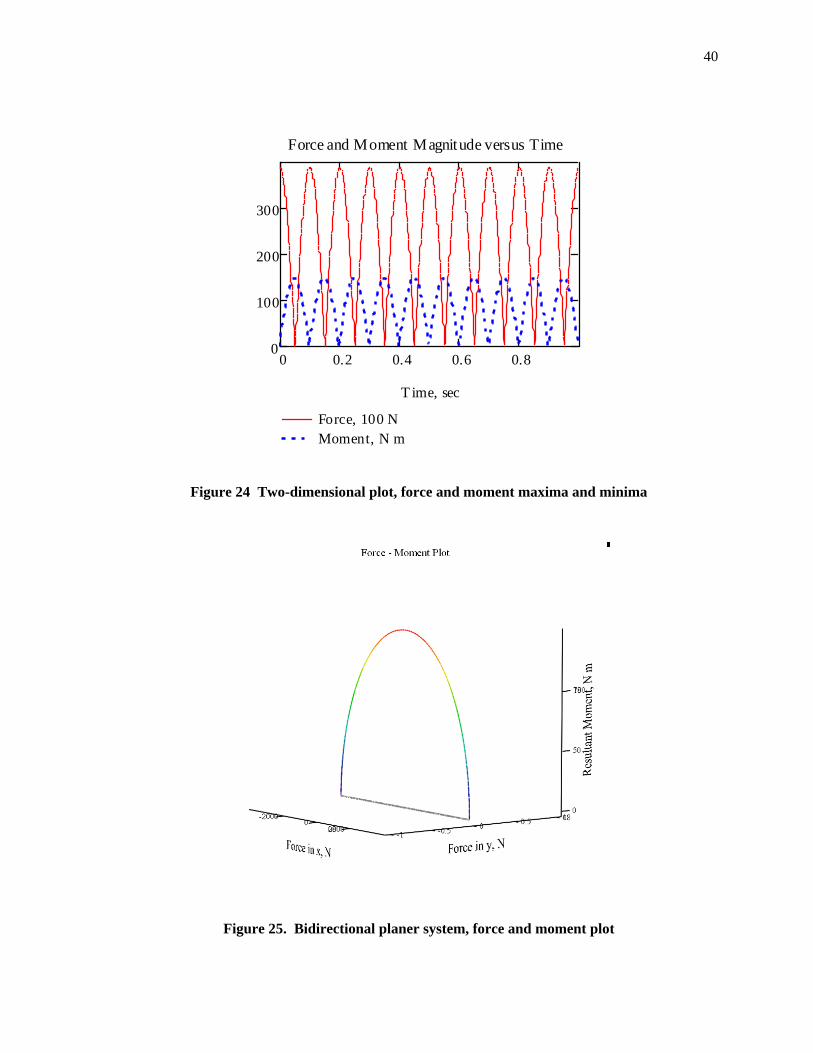
The three-dimensional plot of the force and moment relationship clearly shows the system is not
planer (Figure 25). In Figure 25, the original planer plot is shadowed in the x-y plane.
40
Figure 24 Two-dimensional plot, force and moment maxima and minima
Figure 25. Bidirectional planer system, force and moment plot
0 0.2 0.4 0.6 0.80
100
200
300
Force, 100 N
Moment, N m
Force and Moment Magnitude versus Time
T ime, sec

41
In discussing the energy-wheel dynamic, it is also important to understand the moment from a
reference datum and the axis “m” versus a global reference frame. In the global reference frame, the
shaker head will appear to tilt, roll, and pivot about the tree. This is the result of the magnitude and
direction of the moment relevant to a local reference frame. Establishing a local reference frame at the
center of rotation of the energy-wheels allows plotting the moment magnitude and direction about the
m-axis. What happens is when the force vectors align the direction of the moment instantaneously
change direction about the m-axis. Using the simplified bi-directional linear model this change in
moment direction can be easily understood.
1. At time t0, the force vectors of both energy-wheels are aligned, and the moment magnitude is
at a minimum; in this special case, the moment is zero and the entire energy transformation is
planer forces Figure 26. In production energy-wheel systems a moment exists about n-axis
due to different masses, angular velocity, and center of gravity location each energy-wheel.
Figure 26. Force and Moment, at time t0
Force - Moment Plot
(t 0 ) – Forces aligned no rotation about m - axis
z
n

42
2. Time, t1, the energy-wheel force vectors are opposing and the moment magnitude is at a
maximum (Figure 27). In this idealized model, all of the energy would be a moment and there
would be no planer forces.
Figure 27. Force and Moment, at time t1
43
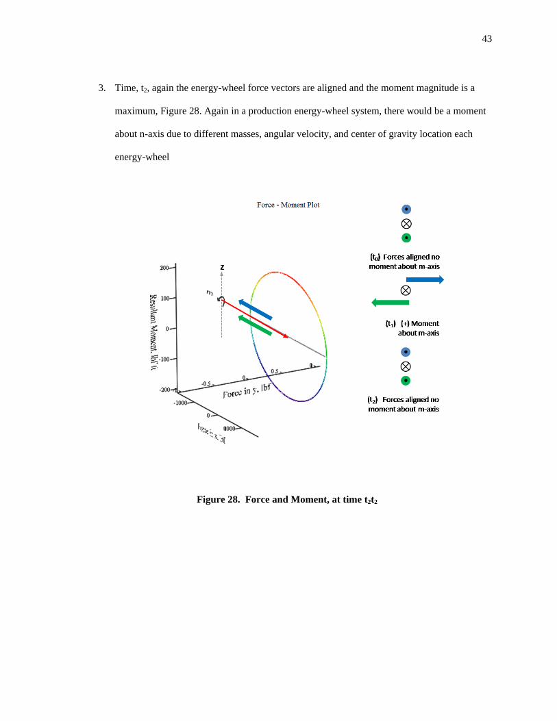
3. Time, t2, again the energy-wheel force vectors are aligned and the moment magnitude is a
maximum, Figure 28. Again in a production energy-wheel system, there would be a moment
about n-axis due to different masses, angular velocity, and center of gravity location each
energy-wheel
Figure 28. Force and Moment, at time t2t2

44
4. Time, t3, again the moment is at a maximum (Figure 29). However, the direction of the
moment has been reversed and is now negative relative to the m-axis. The moment
directional change relative to the m-axis occurs every time the force vectors of the energy-
wheels cross, creating a force maximum.
Figure 29. Force and Moment, at time t3
A more advanced energy-wheel pattern having four force maximums is plotted in Figure 30,
below. As is clearly seen at point A, the planer maximum is aligned with the moment minimum, and
point B aligns the moment maximum with the force minimum. The direction of the moment changes
with each crossing of the force maximum, point A.

45
Figure 30. Moment magnitude and direction using local reference frame.
Returning to the modified star where there is a residual moment is due to the mass, vertical
lever arm distance, and the angular velocity of the energy-wheels being different (Figure 31). Starting
at a force maximum at A (Figure 31), the moment plot moves to a positive maximum moment about
m-axis at B, then goes back to a moment minimum/force maximum at C. At C, the planer force
maximum, there still exists a residual moment created by the mass, mass center, and angular velocity
differences between the two energy-wheels. At this instantaneous point C, the resulting moment
magnitude is about the n-axis. At the next time increment, the direction of the moment about the m-
axis changes sign. The moment goes to the next moment maximum D, and another minimum E. The
magnitude of this residue moment in the sample plot is approximately 100 N m
Force - Moment Plot
A
BPlaner Plot
Moment Plot

46
Figure 31. Peak to peak with negative moment
Force - Moment Plot
A
B
C
D

47
SYSTEM EFFICIENCY
With discussion of the force and moments complete, the following analysis focussed on the
system efficiency of transferring useful forces to the tree, using a simplified model developed with
the following assumptions:
1. All x-axis forces are transferable to the tree trunk.
2. No y and z-axis forces are transferred.
3. No moment forces transfer. Moments are diffused or cancelled by the pads, slings, sling
lubrication, and the suspending structure.
By idealizing the slings and pad system to a non-form fitting system and establishing the
coefficient of friction between the slings as zero, then the only forces the shaker can transfer to the
tree are normal to the sling friction surface. Due to the absence of friction, all moments and the y and
z-axis would be allowed to slip until resisting forces from the frame and hanger balanced the system.
The modified star has the same interaction of moments and forces as the simplified
bidirectional linear model. The difference is the modified star pattern requires the energy-wheels have
different mass, angular velocity, and center of gravity locations, which causes there to be both residue
moments and forces. This is represented by the fact that neither the force or the moment ever have a
zero value, shown in Figure 32.
The three-dimensional plot has a shadow plot in the (x-y) plane of Figure 33 to provide visual
reference to the previously discussed planer shaker-head pattern and the corresponding moment
magnitude. The magnitude of the moment is normalized to better illustrate the relationship between
plane forces. The energy-wheel moments cause the shaker head to roll, tilt, or pivot relative to the tree
trunk and the reaction forces of the transportation system. The reactions at the trunk must be
dissipated by the slings lubrication as torsion and sliding, or the bark can be damaging. The moments

48
generated by stacked rotating mass energy-wheels are non-normal forces and represent a significant
consumption of energy. In addition to the slings and pads dissipating energy, the shaker head
transporter must also dissipate reaction forces of the moments resulting in friction, heat, and structural
strain.
Figure 32. Planer plot of moment and force magnitude for the modified star shaker pattern,
100% y-axis displacement efficiency.
0 0.2 0.4 0.6 0.80
200
400
Force, 10 N
Moment, N m
Force and Moment Magnitude versus Time
T ime, sec

49
Figure 33. Plot of moment and force magnitude for the modified star shaker pattern, 100% y-
axis displacement efficiency.
Abdel-Fattah (2003) found the efficiency of the slings and pads to transmit non-normal
displacement to the tree trunk in the y-axis averaged 66%. The deflection of the tree is proportional to
the forces if modulus of elasticity and diameter are constant, and the trunk is assumed rigidly
mounted cantilevered beam. Using this information on the modified star pattern an efficiency variable
(ηy) is applied to the stacked eccentric mass energy-wheel system model and set to 66%. The loss of
force transfer in the y-axis is visible in both Figure 34 and Figure 35.
Force - Moment Plot

50
Figure 34. Planer plot of moment and force magnitude for the modified star shaker pattern,
66% y-axis displacement efficiency.
Figure 35. Plot of moment and force magnitude for the modified star shaker pattern, 66% y-
axis displacement efficiency.
0 0.2 0.4 0.6 0.80
200
400
Force, 10 N
Moment, N m
Force and Moment Magnitude versus Time
T ime, sec
Force - Moment Plot
51
DISCUSSION OF FINDINGS
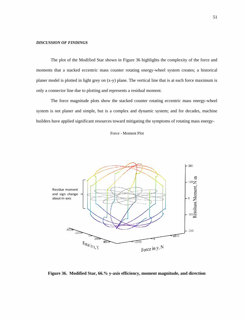
The plot of the Modified Star shown in Figure 36 highlights the complexity of the force and
moments that a stacked eccentric mass counter rotating energy-wheel system creates; a historical
planer model is plotted in light grey on (x-y) plane. The vertical line that is at each force maximum is
only a connector line due to plotting and represents a residual moment.
The force magnitude plots show the stacked counter rotating eccentric mass energy-wheel
system is not planer and simple, but is a complex and dynamic system; and for decades, machine
builders have applied significant resources toward mitigating the symptoms of rotating mass energy-
Figure 36. Modified Star, 66.% y-axis efficiency, moment magnitude, and direction
Force - Moment Plot
Residue moment
and sign changeabout m-axis

52
wheels without knowledge of the true dynamics of the system, i.e. the moments. Therefore, proposed
solutions to tree damage and equipment failure were based on presumptions. An example of such a
solution is the installation of a free sliding mass at the rear of the shaker head claiming to be a force
generator (Figure 37). Matthews (1991) claimed it solved the cause of damaging forces:
This invention; a mass mounted upon a tree shaking device in such a manner so that
the forces generated by the weight alignment are either blocked or regenerated as
force back to the tree. This invention solves the problem of rotational forces pivoting
about the tree. The attempts to solve this problem have heretofore been dealing with
the affect. This invention eliminates the cause. (p 1, line 61-68)
Figure 37. Tree shaker force regenerator
Recent trends toward timing the energy-wheels on the same plane using the planer model
assumptions, will still result in the moments causing damage and requiring additional hardware and
increased transportation structure size to dissipate or absorb the energy. With a system of planer
eccentric masses there will be a reduction in moments about the x and y-axis; on the other hand,
moment about a z-axis could cause excessive rotation about the tree trunk, causing barking. The
displacement about a z-axis will again require the constraining of the system by the carrier structure

53
to prevent the moment from occurring around the tree or mechanical systems to dissipate the non-
normal forces. This again would drive the physical size of the transportation system larger.
More analysis is required to determine if the vertical displacement discovered by Abdel-
Fattah (2003) effects a maximum positive moment about the x-axis (Figure 12). This would make
sense, since when the moment’s maximum is about the x-axis; the rear hangers see a tension force
and the two front hangers see a compressive force. The front hangers under compressive force slide
off axis, collapsing, and allowing a vertical displacement of the shaker head. Since there are no planer
forces that could apply a vertical lifting of the tree, moments could be a very viable explanation to
this movement.
In the presented models, the x-axis forces are assumed 100% transferred and the y-axis force
is assumed at 66% transferred into displacement. After the tree has been displaced, and the forces
vector diminishes to a value less than the tree restitution forces, the tree will become the driver and
the forces applied in the x-y axis may not contribute to the shaking energy and represent additional
losses. The pads and slings again would dissipate non-normal forces further reducing the overall
efficiency of energy transfer to the tree.
There are significant problems related to the current mechanized tree harvesting systems
regarding tree damage; however, the cost of stopping mechanical harvesting is too great. As long as
rotational energy is the basic system for tree stimulation, there will be unwanted forces that need to be
dissipated or constrained. Without a systematic analysis of the customer requirements, tree response,
and hardware optimization, the deficiencies of the system will continue.

54
CONCLUSIONS
First, the resulting forces of a stacked counter rotating eccentric mass energy-wheel system
are not simply planer. The moments generated by the energy-wheel system are significant in
magnitude and are non-value added. Moments will exist in any vibration system using rotating
eccentric masses weight in a stacked or planer orientation. With the existence of moment energy
dissipating systems such as the slings, pad, and suspension systems will be required to minimize the
potential for tree damage. The continued belief that the system is planer will not inspire engineered
solutions reducing tree damage, improving system efficiency, or increasing the diversity of
application of mechanical tree harvesting.
Second, moments (Mx, My, and Mz) and forces (Fx, Fy, and Fz) do not and cannot be negated
in a typical stacked counter rotating energy-wheel system by mechanical timing. There are always
residue moments at the planer force maxima and residue forces at the moment maxima, except in
special simplified cases.
Third, moments are possibly the most damaging force to the biological structure of tree
trunks. Without proper sling lubrication, moments are possibly the largest contributing force to
barking and vertical tree displacement. Engineering solutions that minimize or eliminate moments
should increase the productive life of an orchard, minimize individual tree damage, reduce harvest
cost, and reduce stress related to the cultural requirement of mechanical tree harvesting.

55
FUTURE RESEARCH
1. Tree shaker and trunk response analysis at the clamp zone using a three-dimensional driver
model.
2. Analysis of the moments of tree shaker head and the displacement of the tree trunk.
3. Repeat the Abedel-Fattah (2003) research and recored the energy wheel speed, hyraulic
motor oil pressure, and add six axis accellerometers to calculate the system efficiency.
ACKNOWLEDGEMENT
A special thanks to Teresa A. Snell, my wife for patiently supporting me throughout ten years
of late nights, early mornings, and the untold cost for classes, computer hardware, software, data
collection systems, travel expenses, and other incurred academic expenses. We are beginning to
complete a long and special journey.
To Dr. Stuart Birrell, for having the vision to see the potential of this research and creating
opportunities to rekindle my dream of engineering a better tree shaker.

56
REFERENCES
Abedel-Fattah, H. S. (2003). Substantial Vertical Tree Displacements During Almond Shaker
Harvesting. Applied Engineering in Agriculture , Vol19(2) 145-150.
Almond Board of California. (2007). 2007 Almond Almanac, Document #5260.
Almond Board of California. (2008). Almond Board. Retrieved July 17, 2008, from Life cycle of
almonds:
http://www.almondboard.com/content/eLearning/lifecycle_of_almond_course/htmls/main.ht
m
Bell, J. (2001, Autumn). American Forests. Retrieved July 19, 2008, from The Tasty Pecan:
http://www.americanforests.org/productsandpubs/magazine/archives/2001autumn/inprofile.p
hp
Blue Diamond Growers. (2008). Blue Diamond. Retrieved May 6, 2008, from Growers:
http://www.bluediamond.com/growers/techniques/cultural/all_shook_up.cfm
Chiel, D., & Zehavi, E. (1998). Patent No. 5,816,037. Afula Ilit, IL.
Clarence E. Hood, J., Alper, Y., & Webb, B. K. (1979). Patent No. 4,170,100. Clemson, S.C.
Compton, I. (1990). Patent No. 4,921,073. Chico, CA.
Compton, I. (1990b). Patent No. 4,921,073. Chico, CA.
Compton, I. (1990a). Patent No. 4,932,195. Chico, CA.
Compton, I. (1995). Patent No. 5,467,588. Chico, CA.
Davis, D. (2008, June). Manager, Alina Farms, McFarland, CA. (L. Snell, Interviewer)
Ferrari, T. E., & Evans, D. (2002). Patent No. 6,474,055. Bakersfield, CA.
Freeman, M. W., Viveros, M. A., Klonsky, K. M., & De Moura, R. L. (2008). Sample cost to
establish an almond orchard and produce almonds. University of California Cooperative
Extension , 20.

57
Herrera, E. (2000, May). Historical Background of Pecan Plantings in the Western Region. Retrieved
July 22, 2008, from http://www.cahe.nmsu.edu/pubs/_h/h-626.html
Hill, D. G. (1997). Patent No. 5,563,097. Yakima, WA.
Mattews, C. D. (1991). Patent No. 4,998,402. Sutter, CA.
Mayo, D. P. (2002). Patent No. 6,658,834. Yuba City, CA.
McConnell, J. L., & Edwards, J. L. (1990). New Techniques for Tree Shaking of Older Seed
Orchards. Tree Planters' Notes , 26-28.
McCrill, K. L. (1992). Patent No. 5,103,625. Sutter, CA.
Michelson, Y. (1998). Patent No. 5,765,349. 37000 Pardes Hanna, IL.
Moser Fruit Tree Sales, Inc. (n.d.). The New Fruit Grower. Retrieved July 19, 2008, from Training
systems: http://www.thenewfruitgrower.com/training_systems.htm
Mosz, N. (2002, Jan 14). Pistachio Timeline. Retrieved July 19, 2008, from
http://pestdata.ncsu.edu/cropTimelines/pdf/CApistachio.pdf
Orchard Machinery Corporation. (2007). Sales brochure. 2700 Colusa Highway, Yuba City, CA
95993.
Reynolds, S. d., Domingos, P., Vieira, C. d., & Pedro, J. (1997). Patent No. 5,595,054.
Savage, B. W. (1981). Patent No. 4,275,548. Madill, OK.
Srivastava, A. K., Goering, C. E., & Rohrbach, R. P. (1996). Engineering Principles of Agricultural
Machines. (P. DeVore-Hansen, Ed.) St. Joseph: American Society of Agricultural Engineers.
Stout, B. A. (1999). CIGR Handbook of Agricultural Engineering, Vol. III Plant Production
Engineering. American Society of Agricultural Engineers.
United State Department of Agriculture. (2007). Noncitrus Fruits and Nuts 2007 Summary. National
Agricultrual Statistic Service.
58
US Department of Agriculture, Forest Service, Forest Products Laboratory. (1999). Mechanical
Properties of Wood. In D. W. Green, J. E. Winandy, & D. E. Krestschmann, Wood book -
Wood as an engineering material (pp. Chapeter 4, p.4-8). Madison, WI.
Walnut Marketing Board. (2008, May). Walnuts, Commodity Fact Sheet. Retrieved July 19, 2008,
from http://www.cfaitc.org/Commodity/pdf/Walnuts.pdf
Westerguard, R. (1983). Patent No. 4409782. Ceres, CA.
Zehavi, E., & Chiel, D. (1995 ). Patent No. 5,473,875. Kiriat Tivon 36000, IL.
Zehavi, E., & Chiel, D. (2005 ). Patent No. 6,978,591. Kiryat Tivon, IL.

59
APPENDIX A. STAR PLOTS THEORETICAL VS. 66% Y-AXIS EFFICIENCY
(US units)
0 0.2 0.4 0.6 0.80
500
1 103
1.5 103
Force, lbf
Moment , lbf * ft
Force and Moment Magnitude versus Time
T ime, sec
Force - Moment Plot

60
APPENDIX B. THINNING PLOTS THEORETICAL VS. 66% Y-AXIS EFFICIENCY
(US units)
0 0.2 0.4 0.6 0.80
500
1 103
1.5 103
Force, lbf
Moment , lbf * ft
Force and Moment Magnitude versus Time
T ime, sec
Force - Moment Plot

61
APPENDIX C. SPIRAL ORBIT PLOTS THEORETICAL VS. 66% Y-AXIS
EFFICIENCY
(US Units)
0 0.1 0.20
500
1 103
1.5 103
Force, lbf
Moment , lbf * ft
Force and Moment Magnitude versus Time
T ime, sec
Force - Moment Plot

62
APPENDIX D. TRIANGLE PLOTS THEORETICAL VS. 66% Y-AXIS
EFFICIENCY
(US Units)
0 0.2 0.4 0.6 0.80
500
1 103
Force, lbf
Moment, lbf * ft
Force and Moment Magnitude versus Time
T ime, sec
Force - Moment Plot

63
APPENDIX E. CRYSTAL BALL SAMPLE CODE FOR TREE 1 AND 2
Damage logic
Gross harvest distribution
Code
Damage % 0.01
Prod. / Tree =Sheet2!C15
StDev / Tree =Sheet2!C16

64
Acres, hectare 1 =C9+C15+C21+C27+C33+C39+C45+C51+C57+C63+C69+C75+C81+C87+C93+C99+C105+C111+C117+C123+C129
=D9+D15+D21+D27+D33+D39+D45+D51+D57+D63+D69+D75+D81+D87+D93+D99+D105+D111+D117+D123+D129
Tree Number 1 =C6+1
Age 5 5 5
Damage Logic 0 0
Harvest Logic =IF(C7>=5,1,0) =IF(D7>=5,1,0)
Gross Harvest 0 0
Net Harvest =C10*C9 =D10*D9
Age =B7+1 =IF(AND(C8=1,C7>=5),0,C7+1) =IF(AND(D8=1,D7>=5),0,D7+1)
Damage Logic 0 0
Harvest Logic =IF(C13>=5,1,0) =IF(D13>=5,1,0)
Gross Harvest 0 0
Net Harvest =C16*C15 =D16*D15
Age =B13+1 =IF(AND(C14=1,C13>=5),0,C13+1) =IF(AND(D14=1,D13>=5),0,D13+1)
Damage Logic 0 0
Harvest Logic =IF(C19>=5,1,0) =IF(D19>=5,1,0)
Gross Harvest 0 0
Net Harvest =C22*C21 =D22*D21
Age =B19+1 =IF(AND(C20=1,C19>=5),0,C19+1) =IF(AND(D20=1,D19>=5),0,D19+1)
Damage Logic 0 0
Harvest Logic =IF(C25>=5,1,0) =IF(D25>=5,1,0)
Gross Harvest 0 0
Net Harvest =C28*C27 =D28*D27
Age =B25+1 =IF(AND(C26=1,C25>=5),0,C25+1) =IF(AND(D26=1,D25>=5),0,D25+1)
Damage Logic 0 0
Harvest Logic =IF(C31>=5,1,0) =IF(D31>=5,1,0)
Gross Harvest 0 0
Net Harvest =C34*C33 =D34*D33
Age =B31+1 =IF(AND(C32=1,C31>=5),0,C31+1) =IF(AND(D32=1,D31>=5),0,D31+1)
Damage Logic 0 0
Harvest Logic =IF(C37>=5,1,0) =IF(D37>=5,1,0)
Gross Harvest 0 0
Net Harvest =C40*C39 =D40*D39
Age =B37+1 =IF(AND(C38=1,C37>=5),0,C37+1) =IF(AND(D38=1,D37>=5),0,D37+1)

65
Damage Logic 0 0
Harvest Logic =IF(C43>=5,1,0) =IF(D43>=5,1,0)
Gross Harvest 0 0
Net Harvest =C46*C45 =D46*D45
Age =B43+1 =IF(AND(C44=1,C43>=5),0,C43+1) =IF(AND(D44=1,D43>=5),0,D43+1)
Damage Logic 0 0
Harvest Logic =IF(C49>=5,1,0) =IF(D49>=5,1,0)
Gross Harvest 0 0
Net Harvest =C52*C51 =D52*D51
Age =B49+1 =IF(AND(C50=1,C49>=5),0,C49+1) =IF(AND(D50=1,D49>=5),0,D49+1)
Damage Logic 0 0
Harvest Logic =IF(C55>=5,1,0) =IF(D55>=5,1,0)
Gross Harvest 0 0
Net Harvest =C58*C57 =D58*D57
Age =B55+1 =IF(AND(C56=1,C55>=5),0,C55+1) =IF(AND(D56=1,D55>=5),0,D55+1)
Damage Logic 0 0
Harvest Logic =IF(C61>=5,1,0) =IF(D61>=5,1,0)
Gross Harvest 0 0
Net Harvest =C64*C63 =D64*D63
Age =B61+1 =IF(AND(C62=1,C61>=5),0,C61+1) =IF(AND(D62=1,D61>=5),0,D61+1)
Damage Logic 0 0
Harvest Logic =IF(C67>=5,1,0) =IF(D67>=5,1,0)
Gross Harvest 0 0
Net Harvest =C70*C69 =D70*D69
Age =B67+1 =IF(AND(C68=1,C67>=5),0,C67+1) =IF(AND(D68=1,D67>=5),0,D67+1)
Damage Logic 0 0
Harvest Logic =IF(C73>=5,1,0) =IF(D73>=5,1,0)
Gross Harvest 0 0
Net Harvest =C76*C75 =D76*D75
Age =B73+1 =IF(AND(C74=1,C73>=5),0,C73+1) =IF(AND(D74=1,D73>=5),0,D73+1)
Damage Logic 0 0
Harvest Logic =IF(C79>=5,1,0) =IF(D79>=5,1,0)
Gross Harvest 0 0
Net Harvest =C82*C81 =D82*D81
Age =B79+1 =IF(AND(C80=1,C79>=5),0,C79+1) =IF(AND(D80=1,D79>=5),0,D79+1)

66
Damage Logic 0 0
Harvest Logic =IF(C85>=5,1,0) =IF(D85>=5,1,0)
Gross Harvest 0 0
Net Harvest =C88*C87 =D88*D87
Age =B85+1 =IF(AND(C86=1,C85>=5),0,C85+1) =IF(AND(D86=1,D85>=5),0,D85+1)
Damage Logic 0 0
Harvest Logic =IF(C91>=5,1,0) =IF(D91>=5,1,0)
Gross Harvest 0 0
Net Harvest =C94*C93 =D94*D93
Age =B91+1 =IF(AND(C92=1,C91>=5),0,C91+1) =IF(AND(D92=1,D91>=5),0,D91+1)
Damage Logic 0 0
Harvest Logic =IF(C97>=5,1,0) =IF(D97>=5,1,0)
Gross Harvest 0 0
Net Harvest =C100*C99 =D100*D99
Age =B97+1 =IF(AND(C98=1,C97>=5),0,C97+1) =IF(AND(D98=1,D97>=5),0,D97+1)
Damage Logic 0 0
Harvest Logic =IF(C103>=5,1,0) =IF(D103>=5,1,0)
Gross Harvest 0 0
Net Harvest =C106*C105 =D106*D105
Age =B103+1 =IF(AND(C104=1,C103>=5),0,C103+1) =IF(AND(D104=1,D103>=5),0,D103+1)
Damage Logic 0 0
Harvest Logic =IF(C109>=5,1,0) =IF(D109>=5,1,0)
Gross Harvest 0 0
Net Harvest =C112*C111 =D112*D111
Age =B109+1 =IF(AND(C110=1,C109>=5),0,C109+1) =IF(AND(D110=1,D109>=5),0,D109+1)
Damage Logic 0 0
Harvest Logic =IF(C115>=5,1,0) =IF(D115>=5,1,0)
Gross Harvest 0 0
Net Harvest =C118*C117 =D118*D117
Age =B115+1 =IF(AND(C116=1,C115>=5),0,C115+1) =IF(AND(D116=1,D115>=5),0,D115+1)
Damage Logic 0 0
Harvest Logic =IF(C121>=5,1,0) =IF(D121>=5,1,0)
Gross Harvest 0 0
Net Harvest =C124*C123 =D124*D123
Age =B121+1 =IF(AND(C122=1,C121>=5),0,C121+1) =IF(AND(D122=1,D121>=5),0,D121+1)

67
Damage Logic 0 0
Harvest Logic =IF(C127>=5,1,0) =IF(D127>=5,1,0)
Gross Harvest 0 0
Net Harvest =C130*C129 =D130*D129
Age =B127+1 =IF(AND(C128=1,C127>=5),0,C127+1) =IF(AND(D128=1,D127>=5),0,D127+1)
Damage Logic 0 0
Harvest Logic =IF(C133>=5,1,0) =IF(D133>=5,1,0)
Gross Harvest 0 0
Net Harvest =C136*C135 =D136*D135
Age =B133+1 =IF(AND(C134=1,C133>=5),0,C133+1) =IF(AND(D134=1,D133>=5),0,D133+1)
Damage Logic 0 0
Harvest Logic =IF(C139>=5,1,0) =IF(D139>=5,1,0)
Gross Harvest 0 0
Net Harvest =C142*C141 =D142*D141
Age =B139+1 =IF(AND(C140=1,C139>=5),0,C139+1) =IF(AND(D140=1,D139>=5),0,D139+1)
Damage Logic 0 0
Harvest Logic =IF(C145>=5,1,0) =IF(D145>=5,1,0)
Gross Harvest 0 0
Net Harvest =C148*C147 =D148*D147
Age =B145+1 =IF(AND(C146=1,C145>=5),0,C145+1) =IF(AND(D146=1,D145>=5),0,D145+1)
Damage Logic 0 0
Harvest Logic =IF(C151>=5,1,0) =IF(D151>=5,1,0)
Gross Harvest 0 0
Net Harvest =C154*C153 =D154*D153
Age =B151+1 =IF(AND(C152=1,C151>=5),0,C151+1) =IF(AND(D152=1,D151>=5),0,D151+1)
Damage Logic 0 0
Harvest Logic =IF(C157>=5,1,0) =IF(D157>=5,1,0)
Gross Harvest 0 0
Net Harvest =C160*C159 =D160*D159

68
Picture of Excel with 242 tree columns
Damage % 0.01
Prod. / Tree 6.9
StDev / Tree 1.4
Acres 1 21 21
20yrs
Prod.
Gross
Potential
20yrs
Prod.
With 1.0%
Shaker
Damage
Number
of Trees in
Productio
n
Lifetime
productio
n loss,
kg/hectar
e
- - -
Tree Number 1 242
Age 5 5 5
Damage Logic 0 0
Harvest Logic 1 1 242
Gross Harvest 0 0 0
Net Harvest 0 0 0
Age 6 6 6
Damage Logic 0 0
Harvest Logic 1 1 242
Gross Harvest 0 0 0
Net Harvest 0 0 0
Age 7 7 7
Damage Logic 0 0
Harvest Logic 1 1 242
Gross Harvest 0 0 0
Net Harvest 0 0 0
Age 8 8 8
Damage Logic 0 0
Harvest Logic 1 1 242
Gross Harvest 0 0 0
Net Harvest 0 0 0
Age 9 9 9
Damage Logic 0 0
Harvest Logic 1 1 242
Gross Harvest 0 0 0
Net Harvest 0 0 0
Age 10 10 10
Damage Logic 0 0
Harvest Logic 1 1 242
Gross Harvest 0 0 0
Net Harvest 0 0 0
Age 11 11 11
Damage Logic 0 0
Harvest Logic 1 1 242
Gross Harvest 0 0 0
Net Harvest 0 0 0
Age 12 12 12
Damage Logic 0 0
Harvest Logic 1 1 242
Gross Harvest 0 0 0
Net Harvest 0 0 0
Age 13 13 13
Damage Logic 0 0
Harvest Logic 1 1 242
Gross Harvest 0 0 0
Net Harvest 0 0 0
Age 14 14 14
Damage Logic 0 0
Harvest Logic 1 1 242
Gross Harvest 0 0 0
Net Harvest 0 0 0
Age 15 15 15
Damage Logic 0 0
Harvest Logic 1 1 242
Gross Harvest 0 0 0
Net Harvest 0 0 0
Age 16 16 16
Damage Logic 0 0
Harvest Logic 1 1 242
Gross Harvest 0 0 0
Net Harvest 0 0 0
Age 17 17 17
Damage Logic 0 0
Harvest Logic 1 1 242
Gross Harvest 0 0 0
Net Harvest 0 0 0
Age 18 18 18
Damage Logic 0 0
Harvest Logic 1 1 242
Gross Harvest 0 0 0
Net Harvest 0 0 0
Age 19 19 19
Damage Logic 0 0
Harvest Logic 1 1 242
Gross Harvest 0 0 0
Net Harvest 0 0 0
Age 20 20 20
Damage Logic 0 0
Harvest Logic 1 1 242
Gross Harvest 0 0 0
Net Harvest 0 0 0
Age 21 21 21
Damage Logic 0 0
Harvest Logic 1 1 242
Gross Harvest 0 0 0
Net Harvest 0 0 0
Age 22 22 22
Damage Logic 0 0
Harvest Logic 1 1 242
Gross Harvest 0 0 0
Net Harvest 0 0 0
Age 23 23 23
Damage Logic 0 0
Harvest Logic 1 1 242
Gross Harvest 0 0 0
Net Harvest 0 0 0
Age 24 24 24
Damage Logic 0 0
Harvest Logic 1 1 242
Gross Harvest 0 0 0
Net Harvest 0 0 0
Age 25 25 25
Damage Logic 0 0
Harvest Logic 1 1 242
Gross Harvest 0 0 0
Net Harvest 0 0 0
Age 26 26 26
Damage Logic 0 0
Harvest Logic 1 1 242
Gross Harvest 0 0 0
Net Harvest 0 0 0
Age 27 27 27
Damage Logic 0 0
Harvest Logic 1 1 242
Gross Harvest 0 0 0
Net Harvest 0 0 0
Age 28 28 28
Damage Logic 0 0
Harvest Logic 1 1 242
Gross Harvest 0 0 0
Net Harvest 0 0 0
Age 29 29 29
Damage Logic 0 0
Harvest Logic 1 1 242
Gross Harvest 0 0 0
Net Harvest 0 0 0
Age 30 30 30
Damage Logic 0 0
Harvest Logic 1 1 242
Gross Harvest 0 0 0
Net Harvest 0 0 0

69
iOracle Crystal Ball (formerly Decisioneering, Inc.)
Version 7.3.1
7700 Technology Way
Denver, Colorado 80237 USA
Main number: +1.303.334.4000
ii Mathcad 14.0
Copyright © 2007 Parametric Technology Corporation
PTC Corporate Headquarters
140 Kendrick Street
Needham, MA 02494 USA
781.370.5000