
for23267 ch01 001-032 - Baidu
32
CHAPTER 1 Introduction 因特网利用有线和无线传输介质,连接了大大小小的计算机系统,允许 用户共享包括文本、图像、声音和视频在内的大量信息,并允许用户之间相 互发送消息。今天我们谈到的网络主要分为两种类型:局域网和广域网。 协议是管理通信的规则集。在协议分层中,我们需要遵循两个原则以提 供双向通信。首先,每一层需要实现两个相反的任务。其次,位于两端每层 下的两个对象应该是等同的。TCP/IP 是一个由 5 个层次组成的层次化协议, 这 5 层为应用层、传输层、网络层、数据链路层和物理层。 互联网的历史开始于 20 世纪 60 年代中期的 ARPA 网。Internet 的诞生 与 Cerf 和 Kahn 的工作以及连接网络的网关出现有很大关系。Internet 的管 理随 Internet 的发展不断演化。ISOC 促进和发起了相关的研究和活动。IAB 是 ISOC 的技术顾问组。IETF 是负责运行问题的工作组论坛。IRTF 为关注于 长期发展研究课题的工作组论坛。ICANN 负责 Internet 域名和地址的管理。 NIC 负责收集和发布有关 TCP/IP 协议的信息。 Internet 标准是完全被测试过的规范。Internet 草案为非官方的工作文档, 具有 6 个月的生命周期。一个草案可能被作为 RFC 文档出版。RFC 经过成熟 阶段并按照要求级别分成不同的类别。 本章介绍计算机网络的基本概念,其主要内容如下: • 1.1 节给出什么是计算机网络,并介绍局域网和广域网的定义。与此同 时,本节还讨论互联网的概念,描述通过互联设备将多个广域网和局域 网连接而形成的 Internet。 • 1.2 节讨论计算机网络中的协议分层问题,介绍协议分层应该遵循的原 则,以及封装 / 解封装和多路复用 / 多路分解的概念。另外,本节还描 述 TCP/IP 的层次结构划分,以及应用层、传输层、网络层、数据链路 层和物理层的主要功能。 • 1.3 节和 1.4 节分别介绍 Internet 的主要发展历程以及 Internet 的管理、 标准制定和标准生命周期。对 Internet 发展历程和管理感兴趣的读者可 以参阅这两节内容。
Transcript of for23267 ch01 001-032 - Baidu

CHAPTER 1Introduction
因特网利用有线和无线传输介质,连接了大大小小的计算机系统,允许
用户共享包括文本、图像、声音和视频在内的大量信息,并允许用户之间相
互发送消息。今天我们谈到的网络主要分为两种类型:局域网和广域网。
协议是管理通信的规则集。在协议分层中,我们需要遵循两个原则以提
供双向通信。首先,每一层需要实现两个相反的任务。其次,位于两端每层
下的两个对象应该是等同的。TCP/IP 是一个由 5 个层次组成的层次化协议,
这 5 层为应用层、传输层、网络层、数据链路层和物理层。
互联网的历史开始于 20 世纪 60 年代中期的 ARPA 网。Internet 的诞生
与 Cerf 和 Kahn 的工作以及连接网络的网关出现有很大关系。Internet 的管
理随 Internet 的发展不断演化。ISOC 促进和发起了相关的研究和活动。IAB
是 ISOC 的技术顾问组。IETF 是负责运行问题的工作组论坛。IRTF 为关注于
长期发展研究课题的工作组论坛。ICANN 负责 Internet 域名和地址的管理。
NIC 负责收集和发布有关 TCP/IP 协议的信息。
Internet 标准是完全被测试过的规范。Internet 草案为非官方的工作文档,
具有 6 个月的生命周期。一个草案可能被作为 RFC 文档出版。RFC 经过成熟
阶段并按照要求级别分成不同的类别。
本章介绍计算机网络的基本概念,其主要内容如下:
• 1.1 节给出什么是计算机网络,并介绍局域网和广域网的定义。与此同
时,本节还讨论互联网的概念,描述通过互联设备将多个广域网和局域
网连接而形成的 Internet。
• 1.2 节讨论计算机网络中的协议分层问题,介绍协议分层应该遵循的原
则,以及封装 / 解封装和多路复用 / 多路分解的概念。另外,本节还描
述 TCP/IP 的层次结构划分,以及应用层、传输层、网络层、数据链路
层和物理层的主要功能。
• 1.3 节和 1.4 节分别介绍 Internet 的主要发展历程以及 Internet 的管理、
标准制定和标准生命周期。对 Internet 发展历程和管理感兴趣的读者可
以参阅这两节内容。
2 CHAPTER 1 INTRODUCTION
1.1 OVERVIEW OF THE INTERNETAlthough the goal of this book is to discuss the Internet, a system that interconnects bil-lions of computers in the world, we think of the Internet not as a single network, but asan internetwork, a combination of networks. Therefore, we start our journey by firstdefining a network. We then show how we can connect networks to create small inter-networks. Finally, we show the structure of the Internet and open the gate to study theInternet in the next ten chapters.
1.1.1 NetworksA network is the interconnection of a set of devices capable of communication. In thisdefinition, a device can be a host (or an end system as it is sometimes called) such as alarge computer, desktop, laptop, workstation, cellular phone, or security system. Adevice in this definition can also be a connecting device such as a router which con-nects the network to other networks, a switch which connects devices together, amodem (modulator-demodulator) that changes the form of data, and so on. Thesedevices in a network are connected using wired or wireless transmission media such ascable or air. When we connect two computers at home using a plug-and-play router, wehave created a network, although very small.
Local Area Network
A local area network (LAN) is usually privately owned and connects some hosts in asingle office, building, or campus. Depending on the needs of an organization, a LANcan be as simple as two PCs and a printer in someone’s home office, or it can extendthroughout a company and include audio and video devices. Each host in a LAN has anidentifier, an address, that uniquely defines the host in the LAN. A packet sent by a hostto another host carries both the source host’s and the destination host’s addresses.
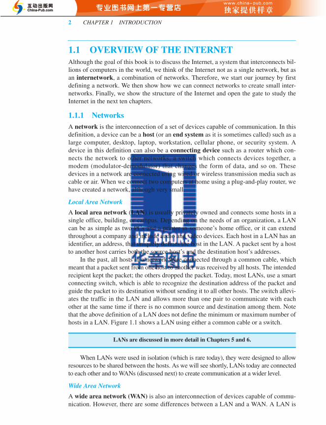
In the past, all hosts in a network were connected through a common cable, whichmeant that a packet sent from one host to another was received by all hosts. The intendedrecipient kept the packet; the others dropped the packet. Today, most LANs, use a smartconnecting switch, which is able to recognize the destination address of the packet andguide the packet to its destination without sending it to all other hosts. The switch allevi-ates the traffic in the LAN and allows more than one pair to communicate with eachother at the same time if there is no common source and destination among them. Notethat the above definition of a LAN does not define the minimum or maximum number ofhosts in a LAN. Figure 1.1 shows a LAN using either a common cable or a switch.
When LANs were used in isolation (which is rare today), they were designed to allowresources to be shared between the hosts. As we will see shortly, LANs today are connectedto each other and to WANs (discussed next) to create communication at a wider level.
Wide Area Network
A wide area network (WAN) is also an interconnection of devices capable of commu-nication. However, there are some differences between a LAN and a WAN. A LAN is
LANs are discussed in more detail in Chapters 5 and 6.
for23267_ch01_001-032.fm Page 2 Monday, January 31, 2011 2:32 PM
SECTION 1.1 OVERVIEW OF THE INTERNET 3
normally limited in size, spanning an office, a building, or a campus; a WAN has awider geographical span, spanning a town, a state, a country, or even the world. A LANinterconnects hosts; a WAN interconnects connecting devices such as switches, routers,or modems. A LAN is normally privately owned by the organization that uses it; aWAN is normally created and run by communication companies and leased by an orga-nization that uses it. We see two distinct examples of WANs today: point-to-pointWANs and switched WANs.
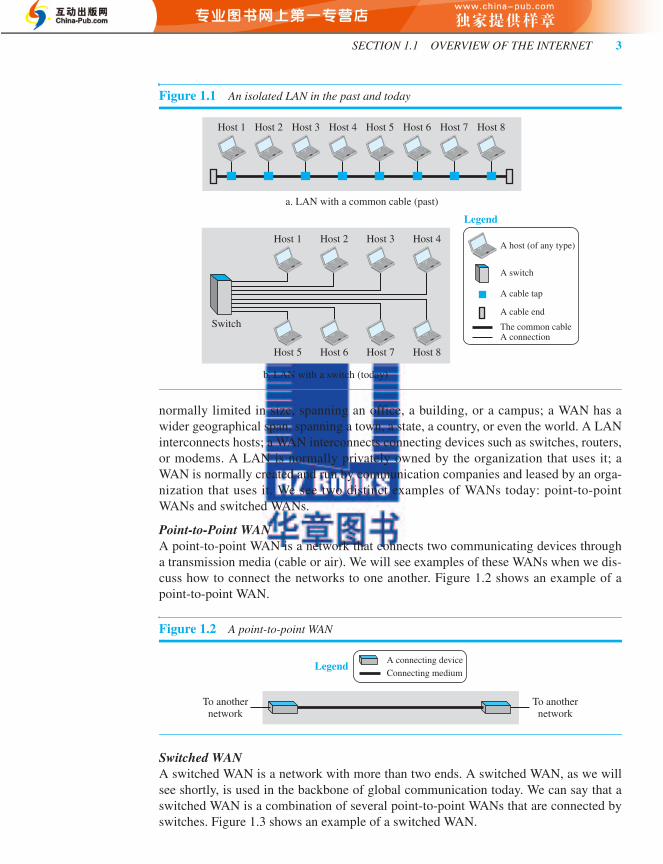
Point-to-Point WANA point-to-point WAN is a network that connects two communicating devices througha transmission media (cable or air). We will see examples of these WANs when we dis-cuss how to connect the networks to one another. Figure 1.2 shows an example of apoint-to-point WAN.
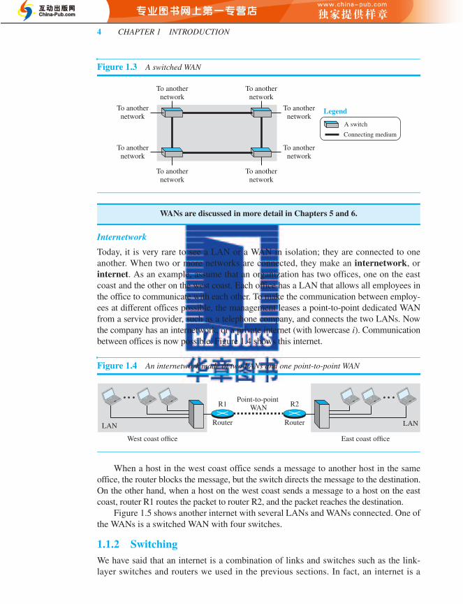
Switched WANA switched WAN is a network with more than two ends. A switched WAN, as we willsee shortly, is used in the backbone of global communication today. We can say that aswitched WAN is a combination of several point-to-point WANs that are connected byswitches. Figure 1.3 shows an example of a switched WAN.
Figure 1.1 An isolated LAN in the past and today
Figure 1.2 A point-to-point WAN
Switch
Host 2 Host 3 Host 4
Host 5 Host 6 Host 7 Host 8
A host (of any type)
A switch
A cable tap
A cable end
A connectionThe common cable
Host 1 Host 2 Host 3 Host 4 Host 5 Host 6 Host 7 Host 8
a. LAN with a common cable (past)
b. LAN with a switch (today)
Legend
Host 1
To anothernetwork
To anothernetwork
LegendA connecting deviceConnecting medium
for23267_ch01_001-032.fm Page 3 Monday, January 31, 2011 2:32 PM
4 CHAPTER 1 INTRODUCTION
Internetwork
Today, it is very rare to see a LAN or a WAN in isolation; they are connected to oneanother. When two or more networks are connected, they make an internetwork, orinternet. As an example, assume that an organization has two offices, one on the eastcoast and the other on the west coast. Each office has a LAN that allows all employees inthe office to communicate with each other. To make the communication between employ-ees at different offices possible, the management leases a point-to-point dedicated WANfrom a service provider, such as a telephone company, and connects the two LANs. Nowthe company has an internetwork, or a private internet (with lowercase i). Communicationbetween offices is now possible. Figure 1.4 shows this internet.
When a host in the west coast office sends a message to another host in the sameoffice, the router blocks the message, but the switch directs the message to the destination.On the other hand, when a host on the west coast sends a message to a host on the eastcoast, router R1 routes the packet to router R2, and the packet reaches the destination.
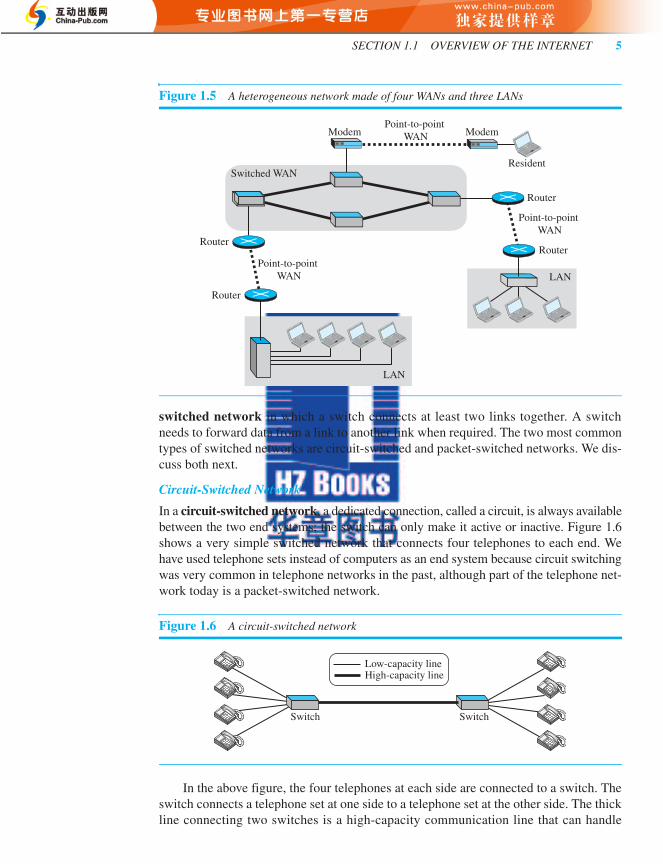
Figure 1.5 shows another internet with several LANs and WANs connected. One ofthe WANs is a switched WAN with four switches.
1.1.2 SwitchingWe have said that an internet is a combination of links and switches such as the link-layer switches and routers we used in the previous sections. In fact, an internet is a
Figure 1.3 A switched WAN
WANs are discussed in more detail in Chapters 5 and 6.
Figure 1.4 An internetwork made of two LANs and one point-to-point WAN
To anothernetwork
To anothernetwork
To anothernetwork
To anothernetwork
To anothernetwork
To anothernetwork
To anothernetwork
To anothernetwork
A switch
Connecting medium
Legend
Point-to-point WAN
Router
R1
East coast officeWest coast office
LAN LANRouter
R2
for23267_ch01_001-032.fm Page 4 Monday, January 31, 2011 2:32 PM
SECTION 1.1 OVERVIEW OF THE INTERNET 5
switched network in which a switch connects at least two links together. A switchneeds to forward data from a link to another link when required. The two most commontypes of switched networks are circuit-switched and packet-switched networks. We dis-cuss both next.
Circuit-Switched Network
In a circuit-switched network, a dedicated connection, called a circuit, is always availablebetween the two end systems; the switch can only make it active or inactive. Figure 1.6shows a very simple switched network that connects four telephones to each end. Wehave used telephone sets instead of computers as an end system because circuit switchingwas very common in telephone networks in the past, although part of the telephone net-work today is a packet-switched network.
In the above figure, the four telephones at each side are connected to a switch. Theswitch connects a telephone set at one side to a telephone set at the other side. The thickline connecting two switches is a high-capacity communication line that can handle
Figure 1.5 A heterogeneous network made of four WANs and three LANs
Figure 1.6 A circuit-switched network
LAN
Switched WAN
Point-to-point WAN
Point-to-point WAN
Point-to-point WAN
LAN
Router
RouterRouter
Router
Modem Modem
Resident
Switch Switch
Low-capacity lineHigh-capacity line
for23267_ch01_001-032.fm Page 5 Monday, January 31, 2011 2:32 PM

6 CHAPTER 1 INTRODUCTION
four voice communications at the same time; the capacity can be shared between allpairs of telephone sets. The switches used in this example have forwarding tasks but nostoring capability.
Let us look at two cases. In the first case, all telephone sets are busy; four people atone site are talking with four people at the other site; the capacity of the thick line isfully used. In the second case, only one telephone set at one side is connected to a tele-phone set at the other side; only one-fourth of the capacity of the thick line is used. Thismeans that a circuit-switched network is efficient only when it is working at its fullcapacity; most of the time, it is inefficient because it is working at partial capacity. Thereason that we need to make the capacity of the thick line four times the capacity ofeach voice line is that we do not want communication to fail when all telephone sets atone side want to be connected with all telephone sets at the other side.
Packet-Switched Network
In a computer network, the communication between the two ends is done in blocks ofdata called packets. In other words, instead of the continuous communication we seebetween two telephone sets when they are being used, we see the exchange of individ-ual data packets between the two computers. This allows us to make the switches func-tion for both storing and forwarding because a packet is an independent entity that canbe stored and sent later. Figure 1.7 shows a small packet-switched network that con-nects four computers at one site to four computers at the other site.
A router in a packet-switched network has a queue that can store and forward thepacket. Now assume that the capacity of the thick line is only twice the capacity of thedata line connecting the computers to the routers. If only two computers (one at eachsite) need to communicate with each other, there is no waiting for the packets.However, if packets arrive at one router when the thick line is already working at its fullcapacity, the packets should be stored and forwarded in the order they arrived. The twosimple examples show that a packet-switched network is more efficient than a circuit-switched network, but the packets may encounter some delays.
In this book, we mostly discuss packet-switched networks. In Chapter 4, we discusspacket-switched networks in more detail and discuss the performance of these networks.
1.1.3 The InternetAs we discussed before, an internet (note the lowercase i) is two or more networks thatcan communicate with each other. The most notable internet is called the Internet
Figure 1.7 A packet-switched network
Router
Queue Queue
Low-capacity lineHigh-capacity line
Router
for23267_ch01_001-032.fm Page 6 Monday, January 31, 2011 2:32 PM

SECTION 1.1 OVERVIEW OF THE INTERNET 7
(uppercase I ), and is composed of thousands of interconnected networks. Figure 1.8shows a conceptual (not geographical) view of the Internet.
The figure shows the Internet as several backbones, provider networks, and cus-tomer networks. At the top level, the backbones are large networks owned by somecommunication companies such as Sprint, Verizon (MCI), AT&T, and NTT. The back-bone networks are connected through some complex switching systems, called peeringpoints. At the second level, there are smaller networks, called provider networks, thatuse the services of the backbones for a fee. The provider networks are connected tobackbones and sometimes to other provider networks. The customer networks are net-works at the edge of the Internet that actually use the services provided by the Internet.They pay fees to provider networks for receiving services.
Backbones and provider networks are also called Internet Service Providers(ISPs). The backbones are often referred to as international ISPs; the provider networksare often referred to as national or regional ISPs.
1.1.4 Accessing the InternetThe Internet today is an internetwork that allows any user to become part of it. Theuser, however, needs to be physically connected to an ISP. The physical connection isnormally done through a point-to-point WAN. In this section, we briefly describehow this can happen, but we postpone the technical details of the connection untilChapters 6 and 7.
Using Telephone Networks
Today most residences and small businesses have telephone service, which meansthey are connected to a telephone network. Since most telephone networks have
Figure 1.8 The Internet today
Customer network
Customer network
Customer network
Customer network
Peeringpoint
Peeringpoint
Providernetwork
Providernetwork
Providernetwork
Backbones
Providernetwork
Customer network
Customer network
Providernetwork
Customer network
Customer network
Customer network
Customer network
for23267_ch01_001-032.fm Page 7 Monday, January 31, 2011 2:32 PM
8 CHAPTER 1 INTRODUCTION
already connected themselves to the Internet, one option for residences and smallbusinesses to connect to the Internet is to change the voice line between the residenceor business and the telephone center to a point-to-point WAN. This can be done intwo ways.
❑ Dial-up service. The first solution is to add to the telephone line a modem thatconverts data to voice. The software installed on the computer dials the ISP andimitates making a telephone connection. Unfortunately, the dial-up service isvery slow, and when the line is used for Internet connection, it cannot be used fortelephone (voice) connection. It is only useful for small residences and busi-nesses with occasional connection to the Internet. We discuss dial-up service inChapter 5.
❑ DSL Service. Since the advent of the Internet, some telephone companies haveupgraded their telephone lines to provide higher speed Internet services to resi-dences or small businesses. The DSL service also allows the line to be used simul-taneously for voice and data communication. We discuss DSL in Chapter 5.
Using Cable Networks
More and more residents over the last two decades have begun using cable TV servicesinstead of antennas to receive TV broadcasting. The cable companies have beenupgrading their cable networks and connecting to the Internet. A residence or a smallbusiness can be connected to the Internet by using this service. It provides a higherspeed connection, but the speed varies depending on the number of neighbors that usethe same cable. We discuss the cable networks in Chapter 5.
Using Wireless Networks
Wireless connectivity has recently become increasingly popular. A household or asmall business can use a combination of wireless and wired connections to access theInternet. With the growing wireless WAN access, a household or a small business canbe connected to the Internet through a wireless WAN. We discuss wireless access inChapter 6.
Direct Connection to the Internet
A large organization or a large corporation can itself become a local ISP and be con-nected to the Internet. This can be done if the organization or the corporation leases ahigh-speed WAN from a carrier provider and connects itself to a regional ISP. Forexample, a large university with several campuses can create an internetwork and thenconnect the internetwork to the Internet.
1.1.5 Hardware and SoftwareWe have given the overview of the Internet structure, which is made of small andlarge networks glued together with connecting devices. It should be clear, however,that if we only connect these pieces nothing will happen. For communication to hap-pen, we need both hardware and software. This is similar to a complex computationin which we need both a computer and a program. In the next section, we show howthese combinations of hardware and software are coordinated with each other usingprotocol layering.
for23267_ch01_001-032.fm Page 8 Monday, January 31, 2011 2:32 PM
SECTION 1.2 PROTOCOL LAYERING 9
1.2 PROTOCOL LAYERINGA word we hear all the time when we talk about the Internet is protocol. A protocoldefines the rules that both the sender and receiver and all intermediate devices need tofollow to be able to communicate effectively. When communication is simple, we mayneed only one simple protocol; when the communication is complex, we may need todivide the task between different layers, in which case we need a protocol at each layer,or protocol layering.
1.2.1 ScenariosLet us develop two simple scenarios to better understand the need for protocol layering.
First Scenario
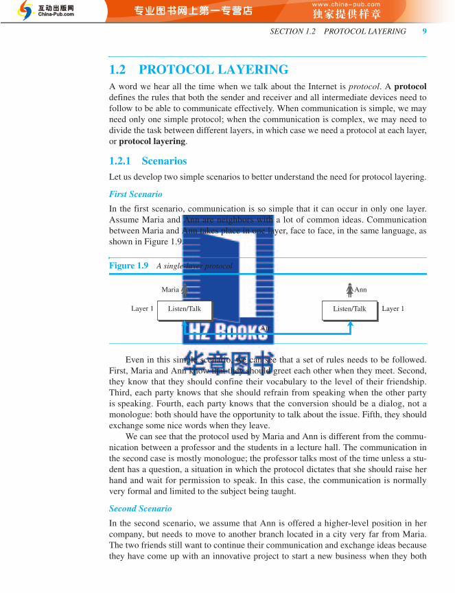
In the first scenario, communication is so simple that it can occur in only one layer.Assume Maria and Ann are neighbors with a lot of common ideas. Communicationbetween Maria and Ann takes place in one layer, face to face, in the same language, asshown in Figure 1.9.
Even in this simple scenario, we can see that a set of rules needs to be followed.First, Maria and Ann know that they should greet each other when they meet. Second,they know that they should confine their vocabulary to the level of their friendship.Third, each party knows that she should refrain from speaking when the other partyis speaking. Fourth, each party knows that the conversion should be a dialog, not amonologue: both should have the opportunity to talk about the issue. Fifth, they shouldexchange some nice words when they leave.
We can see that the protocol used by Maria and Ann is different from the commu-nication between a professor and the students in a lecture hall. The communication inthe second case is mostly monologue; the professor talks most of the time unless a stu-dent has a question, a situation in which the protocol dictates that she should raise herhand and wait for permission to speak. In this case, the communication is normallyvery formal and limited to the subject being taught.
Second Scenario
In the second scenario, we assume that Ann is offered a higher-level position in hercompany, but needs to move to another branch located in a city very far from Maria.The two friends still want to continue their communication and exchange ideas becausethey have come up with an innovative project to start a new business when they both
Figure 1.9 A single-layer protocol
Maria Ann
Layer 1 Listen/Talk Listen/Talk
Air
Layer 1
for23267_ch01_001-032.fm Page 9 Monday, January 31, 2011 2:32 PM

10 CHAPTER 1 INTRODUCTION
retire. They decide to continue their conversion using regular mail through the postoffice. However, they do not want their ideas to be revealed by other people if the let-ters are intercepted. They agree on an encryption/decryption technique. The sender ofthe letter encrypts it to make it unreadable by an intruder; the receiver of the letterdecrypts it to get the original letter. We discuss the encryption/decryption methods inChapter 10, but for the moment we assume that Maria and Ann use one technique thatmakes it hard to decrypt the letter if one does not have the key for doing so. Now wecan say that the communication between Maria and Ann takes place in three layers, asshown in Figure 1.10. We assume that Ann and Maria each have three machines (orrobots) that can perform the task at each layer.
Let us assume that Maria sends the first letter to Ann. Maria talks to the machine atthe third layer as though the machine is Ann and is listening to her. The third layermachine listens to what Maria says and creates the plaintext (a letter in English), whichis passed to the second layer machine. The second layer machine takes the plaintext,encrypts it, and creates the ciphertext, which is passed to the first layer machine. Thefirst layer machine, presumably a robot, takes the ciphertext, puts it in an envelope,adds the sender and receiver addresses, and mails it.
At Ann’s side, the first layer machine picks up the letter from Ann’s mail box, rec-ognizing the letter from Maria by the sender address. The machine takes out the cipher-text from the envelope and delivers it to the second layer machine. The second layermachine decrypts the message, creates the plaintext, and passes the plaintext to thethird-layer machine. The third layer machine takes the plaintext and reads it as thoughMaria is speaking.
Protocol layering enables us to divide a complex task into several smaller and sim-pler tasks. For example, in Figure 1.10, we could have used only one machine to do thejob of all three machines. However, if Maria and Ann decide that the encryption/decryption done by the machine is not enough to protect their secrecy, they have to
Figure 1.10 A three-layer protocol
Maria
Listen/Talk Layer 3 Layer 3
Ann
Listen/Talk
Plaintext Plaintext
Ciphertext Ciphertext
Mail Mail
Encrypt/Decrypt
Send mail/receive mail
Layer 2
Layer 1
Encrypt/Decrypt
Send mail/receive mail
Layer 2
Layer 1
Identical objects
Identical objects
Identical objects
Postal carrier facility
US Post US Post
for23267_ch01_001-032.fm Page 10 Monday, January 31, 2011 2:32 PM
SECTION 1.2 PROTOCOL LAYERING 11
change the whole machine. In the present situation, they need to change only the sec-ond layer machine; the other two can remain the same. This is referred to as modularity.Modularity in this case means independent layers. A layer (module) can be defined as ablack box with inputs and outputs, without concern about how inputs are changed tooutputs. If two machines provide the same outputs when given the same inputs, theycan replace each other. For example, Ann and Maria can buy the second layer machinefrom two different manufacturers. As long as the two machines create the same cipher-text from the same plaintext and vice versa, they do the job.
One of the advantages of protocol layering is that it allows us to separate theservices from the implementation. A layer needs to be able to receive a set of ser-vices from the lower layer and to give the services to the upper layer; we don’t careabout how the layer is implemented. For example, Maria may decide not to buy themachine (robot) for the first layer; she can do the job herself. As long as Maria cando the tasks provided by the first layer, in both directions, the communicationsystem works.
Another advantage of protocol layering, which cannot be seen in our simple exam-ples, but reveals itself when we discuss protocol layering in the Internet, is that commu-nication does not always use only two end systems; there are intermediate systems thatneed only some layers, but not all layers. If we did not use protocol layering, we wouldhave to make each intermediate system as complex as the end systems, which makesthe whole system more expensive.
Is there any disadvantage to protocol layering? One can argue that having a singlelayer makes the job easier. There is no need for each layer to provide a service to theupper layer and give service to the lower layer. For example, Ann and Maria could findor build one machine that could do all three tasks. However, as mentioned above, if oneday they found that their code was broken, each would have to replace the wholemachine with a new one instead of just changing the machine in the second layer.
Principles of Protocol Layering
Let us discuss some principles of protocol layering. The first principle dictates that ifwe want bidirectional communication, we need to make each layer so that it is able toperform two opposite tasks, one in each direction. For example, the third layer task is tolisten (in one direction) and talk (in the other direction). The second layer needs to beable to encrypt and decrypt. The first layer needs to send and receive mail.
The second important principle that we need to follow in protocol layering is thatthe two objects under each layer at both sites should be identical. For example, theobject under layer 3 at both sites should be a plaintext letter. The object under layer 2 atboth sites should be a ciphertext letter. The object under layer 1 at both sites should bea piece of mail.
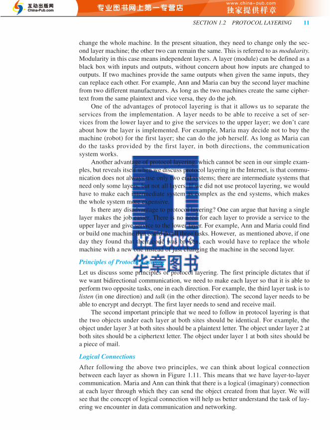
Logical Connections
After following the above two principles, we can think about logical connectionbetween each layer as shown in Figure 1.11. This means that we have layer-to-layercommunication. Maria and Ann can think that there is a logical (imaginary) connectionat each layer through which they can send the object created from that layer. We willsee that the concept of logical connection will help us better understand the task of lay-ering we encounter in data communication and networking.
for23267_ch01_001-032.fm Page 11 Monday, January 31, 2011 2:32 PM
12 CHAPTER 1 INTRODUCTION
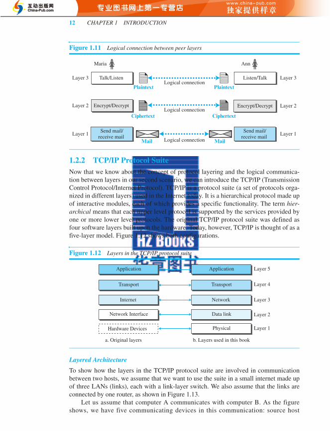
1.2.2 TCP/IP Protocol SuiteNow that we know about the concept of protocol layering and the logical communica-tion between layers in our second scenario, we can introduce the TCP/IP (TransmissionControl Protocol/Internet Protocol). TCP/IP is a protocol suite (a set of protocols orga-nized in different layers) used in the Internet today. It is a hierarchical protocol made upof interactive modules, each of which provides a specific functionality. The term hier-archical means that each upper level protocol is supported by the services provided byone or more lower level protocols. The original TCP/IP protocol suite was defined asfour software layers built upon the hardware. Today, however, TCP/IP is thought of as afive-layer model. Figure 1.12 shows both configurations.
Layered Architecture
To show how the layers in the TCP/IP protocol suite are involved in communicationbetween two hosts, we assume that we want to use the suite in a small internet made upof three LANs (links), each with a link-layer switch. We also assume that the links areconnected by one router, as shown in Figure 1.13.
Let us assume that computer A communicates with computer B. As the figureshows, we have five communicating devices in this communication: source host
Figure 1.11 Logical connection between peer layers
Figure 1.12 Layers in the TCP/IP protocol suite
Plaintext
Maria Ann
Logical connection
Logical connection
Logical connection
Send mail/receive mail
Encrypt/Decrypt Layer 2
Layer 1
Encrypt/Decrypt Layer 2
Talk/Listen Layer 3 Layer 3Listen/Talk
Plaintext
Ciphertext Ciphertext
Send mail/receive mail
Layer 1
Application
Internet
Network Interface
Hardware Devices Layer 1
a. Original layers b. Layers used in this book
Layer 2
Layer 3
Layer 4
Layer 5
Transport
Application
Network
Data link
Physical
Transport
for23267_ch01_001-032.fm Page 12 Monday, January 31, 2011 2:32 PM

SECTION 1.2 PROTOCOL LAYERING 13
(computer A), the link-layer switch in link 1, the router, the link-layer switch in link 2,and the destination host (computer B). Each device is involved with a set of layersdepending on the role of the device in the internet. The two hosts are involved in all fivelayers; the source host needs to create a message in the application layer and send itdown the layers so that it is physically sent to the destination host. The destination hostneeds to receive the communication at the physical layer and then deliver it through theother layers to the application layer.
The router is involved only in three layers; there is no transport or application layerin a router as long as the router is used only for routing. Although a router is alwaysinvolved in one network layer, it is involved in n combinations of link and physical lay-ers in which n is the number of links the router is connected to. The reason is that eachlink may use its own data-link or physical protocol. For example, in the above figure, therouter is involved in three links, but the message sent from source A to destination B isinvolved in two links. Each link may be using different link-layer and physical-layerprotocols; the router needs to receive a packet from link 1 based on one pair of proto-cols and deliver it to link 2 based on another pair of protocols.
A link-layer switch in a link, however, is involved only in two layers, data-link andphysical. Although each switch in the above figure has two different connections, theconnections are in the same link, which uses only one set of protocols. This means that,unlike a router, a link-layer switch is involved only in one data-link and one physicallayer.
Layers in the TCP/IP Protocol Suite
After the above introduction, we briefly discuss the functions and duties of layers inthe TCP/IP protocol suite. Each layer is discussed in detail in the next six chapters ofthe book. To better understand the duties of each layer, we need to think about the
Figure 1.13 Communication through an internet
Link 1
Switch
A
Source (A)
B
C
Destination (B)
Communication from A to B
Router
Router
Link 2
Link 3
Physical
Data link
Network
Transport
Application
PhysicalPhysicalPhysicalPhysical Physical
Data linkData linkData linkData link Data link
NetworkNetwork
Transport
Application
Switch
for23267_ch01_001-032.fm Page 13 Monday, January 31, 2011 2:32 PM

14 CHAPTER 1 INTRODUCTION
logical connections between layers. Figure 1.14 shows logical connections in oursimple internet.
Using logical connections makes it easier for us to think about the duty of eachlayer. As the figure shows, the duty of the application, transport, and network layers isend-to-end. However, the duty of the data-link and physical layers is hop-to-hop, inwhich a hop is a host or router. In other words, the domain of duty of the top threelayers is the internet, and the domain of duty of the two lower layers is the link.
Another way of thinking of the logical connections is to think about the data unitcreated from each layer. In the top three layers, the data unit (packets) should not bechanged by any router or link-layer switch. In the bottom two layers, the packet createdby the host is changed only by the routers, not by the link-layer switches.
Figure 1.15 shows the second principle discussed previously for protocol layering.We show the identical objects below each layer related to each device.
Figure 1.14 Logical connections between layers of the TCP/IP protocol suite
Figure 1.15 Identical objects in the TCP/IP protocol suite
Link 1
LAN
Switch
Logical connections
Sourcehost
Destinationhost
Sourcehost
Destinationhost
Router
Link 2
LAN
Physical
Data link
Network
Transport
Application
Physical
Data link
Network
Transport
Application
Switch
Router
To link 3
Physical
Data link
Network
Transport
Application
Physical
Data link
Identical objects (messages)
Notes: We have not shown switches because they don’t change objects.
Identical objects (segments or user datagrams)
Identical objects (datagrams) Identical objects (datagrams)
Identical objects (frames)
Identical objects (bits) Identical objects (bits)
Identical objects (frames)
Network
Transport
Application
for23267_ch01_001-032.fm Page 14 Monday, January 31, 2011 2:32 PM

SECTION 1.2 PROTOCOL LAYERING 15
Note that, although the logical connection at the network layer is between the twohosts, we can only say that identical objects exist between two hops in this case becausea router may fragment the packet at the network layer and send more packets thanreceived (see fragmentation in Chapter 4). Note that the link between two hops does notchange the object.
Description of Each Layer in TCP/IP
After understanding the concept of logical communication, we are ready to briefly dis-cuss the duty of each layer. Our discussion in this chapter would be very brief, but wecome back to the duty of each layer in next six chapters.
Application LayerAs Figure 1.14 shows, the logical connection between the two application layers is end-to-end. The two application layers exchange messages between each other as thoughthere were a bridge between the two layers. However, we should know that the commu-nication is done through all the layers.
Communication at the application layer is between two processes (two programsrunning at this layer). To communicate, a process sends a request to the other processand receives a response. Process-to-process communication is the duty of the applica-tion layer. The application layer in the Internet includes many predefined protocols, buta user can also create a pair of processes to be run at the two hosts. In Chapter 2, weexplore this situation.
The Hypertext Transfer Protocol (HTTP) is a vehicle for accessing the WorldWide Web (WWW). The Simple Mail Transfer Protocol (SMTP) is the main protocolused in electronic mail (e-mail) service. The File Transfer Protocol (FTP) is used fortransferring files from one host to another. The Terminal Network (TELNET) andSecure Shell (SSH) are used for accessing a site remotely. The Simple Network Man-agement Protocol (SNMP) is used by an administrator to manage the Internet at globaland local levels. The Domain Name System (DNS) is used by other protocols to findthe network-layer address of a computer. The Internet Group Management Protocol(IGMP) is used to collect membership in a group. We discuss most of these protocols inChapter 2 and some in other chapters.
Transport LayerThe logical connection at the transport layer is also end-to-end. The transport layer at thesource host gets the message from the application layer, encapsulates it in a transport-layer packet (called a segment or a user datagram in different protocols) and sends it,through the logical (imaginary) connection, to the transport layer at the destination host.In other words, the transport layer is responsible for giving services to the applicationlayer: to get a message from an application program running on the source host anddeliver it to the corresponding application program on the destination host. We may askwhy we need an end-to-end transport layer when we already have an end-to-end applica-tion layer. The reason is the separation of tasks and duties, which we discussed earlier.The transport layer should be independent of the application layer. In addition, we willsee that we have more than one protocol in the transport layer, which means that eachapplication program can use the protocol that best matches its requirement.
As we said, there are a few transport-layer protocols in the Internet, each designedfor some specific task. The main protocol, Transmission Control Protocol (TCP), is a
for23267_ch01_001-032.fm Page 15 Monday, January 31, 2011 2:32 PM

16 CHAPTER 1 INTRODUCTION
connection-oriented protocol that first establishes a logical connection between trans-port layers at two hosts before transferring data. It creates a logical pipe between twoTCPs for transferring a stream of bytes. TCP provides flow control (matching the send-ing data rate of the source host with the receiving data rate of the destination host toprevent overwhelming the destination), error control (to guarantee that the segmentsarrive at the destination without error and resending the corrupted ones), and conges-tion control to reduce the loss of segments due to congestion in the network. The othercommon protocol, User Datagram Protocol (UDP), is a connectionless protocol thattransmits user datagrams without first creating a logical connection. In UDP, each userdatagram is an independent entity without being related to the previous or the next one(the meaning of the term connectionless). UDP is a simple protocol that does not pro-vide flow, error, or congestion control. Its simplicity, which means small overhead, isattractive to an application program that needs to send short messages and cannotafford the retransmission of the packets involved in TCP, when a packet is corrupted orlost. A new protocol, Stream Control Transmission Protocol (SCTP) is designed torespond to new applications that are emerging in the multimedia. We will discuss UDPand TCP in Chapter 3 and SCTP in Chapter 8.
Network LayerThe network layer is responsible for creating a connection between the source computerand the destination computer. The communication at the network layer is host-to-host.However, since there can be several routers from the source to the destination, the routersin the path are responsible for choosing the best route for each packet. We can say that thenetwork layer is responsible for host-to-host communication and routing the packetthrough possible routes. Again, we may ask ourselves why we need the network layer. Wecould have added the routing duty to the transport layer and dropped this layer. One reason,as we said before, is the separation of different tasks between different layers. The secondreason is that the routers do not need the application and transport layers. Separating thetasks allows us to use fewer protocols on the routers.
The network layer in the Internet includes the main protocol, Internet Protocol(IP), that defines the format of the packet, called a datagram at the network layer. IPalso defines the format and the structure of addresses used in this layer. IP is alsoresponsible for routing a packet from its source to its destination, which is achieved byeach router forwarding the datagram to the next router in its path.
IP is a connectionless protocol that provides no flow control, no error control, andno congestion control services. This means that if any of theses services is required foran application, the application should relay only on the transport-layer protocol. Thenetwork layer also includes unicast (one-to-one) and multicast (one-to-many) routingprotocols. A routing protocol does not take part in routing (it is the responsibility of IP),but it creates forwarding tables for routers to help them in the routing process.
The network layer also has some auxiliary protocols that help IP in its delivery androuting tasks. The Internet Control Message Protocol (ICMP) helps IP to report someproblems when routing a packet. The Internet Group Management Protocol (IGMP) isanother protocol that helps IP in multitasking. The Dynamic Host Configuration Proto-col (DHCP) helps IP to get the network-layer address for a host. The Address Resolu-tion Protocol (ARP) is a protocol that helps IP to find the link-layer address of a host ora router when its network-layer address is given. We discuss ICMP, IGMP, and DHCPin Chapter 4, but we discuss ARP in Chapter 5.
for23267_ch01_001-032.fm Page 16 Monday, January 31, 2011 2:32 PM
SECTION 1.2 PROTOCOL LAYERING 17
Data-link LayerWe have seen that an internet is made up of several links (LANs and WANs) connectedby routers. There may be several overlapping sets of links that a datagram can travelfrom the host to the destination. The routers are responsible for choosing the best links.However, when the next link to travel is determined by the router, the data-link layer isresponsible for taking the datagram and moving it across the link. The link can be awired LAN with a link-layer switch, a wireless LAN, a wired WAN, or a wirelessWAN. We can also have different protocols used with any link type. In each case, thedata-link layer is responsible for moving the packet through the link.
TCP/IP does not define any specific protocol for the data-link layer. It supports allthe standard and proprietary protocols. Any protocol that can take the datagram andcarry it through the link suffices for the network layer. The data-link layer takes a data-gram and encapsulates it in a packet called a frame.
Each link-layer protocol may provide a different service. Some link-layer proto-cols provide complete error detection and correction, some provide only error correc-tion. We discuss wired links in Chapter 5 and wireless links in Chapter 6.
Physical LayerWe can say that the physical layer is responsible for carrying individual bits in a frameacross the link. Although the physical layer is the lowest level in the TCP/IP protocolsuite, the communication between two devices at the physical layer is still a logicalcommunication because there is another, hidden layer, the transmission media, underthe physical layer. Two devices are connected by a transmission medium (cable or air).We need to know that the transmission medium does not carry bits; it carries electricalor optical signals. So the bits received in a frame from the data-link layer are trans-formed and sent through the transmission media, but we can think that the logical unitbetween two physical layers in two devices is a bit. There are several protocols thattransform a bit to a signal. We discuss them in Chapter 7 when we discuss the physicallayer and the transmission media.
Encapsulation and Decapsulation
One of the important concepts in protocol layering in the Internet is encapsulation/decapsulation. Figure 1.16 shows this concept for the small internet in Figure 1.13.
We have not shown the layers for the link-layer switches because no encapsulation/decapsulation occurs in this device. In Figure 1.16, we show the encapsulation in thesource host, decapsulation in the destination host, and encapsulation and decapsulationin the router.
Encapsulation at the Source Host At the source, we have only encapsulation.
1. At the application layer, the data to be exchanged is referred to as a message. Amessage normally does not contain any header or trailer, but if it does, we refer tothe whole as the message. The message is passed to the transport layer.
2. The transport layer takes the message as the payload, the load that the transportlayer should take care of. It adds the transport layer header to the payload, whichcontains the identifiers of the source and destination application programs thatwant to communicate plus some more information that is needed for the end-to-end delivery of the message, such as information needed for flow, error control, or
for23267_ch01_001-032.fm Page 17 Monday, January 31, 2011 2:32 PM

18 CHAPTER 1 INTRODUCTION
congestion control. The result is the transport-layer packet, which is called the seg-ment (in TCP) and the user datagram (in UDP). The transport layer then passes thepacket to the network layer.
3. The network layer takes the transport-layer packet as data or payload and adds itsown header to the payload. The header contains the addresses of the source anddestination hosts and some more information used for error checking of the header,fragmentation information, and so on. The result is the network-layer packet,called a datagram. The network layer then passes the packet to the data-link layer.
4. The data-link layer takes the network-layer packet as data or payload and adds itsown header, which contains the link-layer addresses of the host or the next hop (therouter). The result is the link-layer packet, which is called a frame. The frame ispassed to the physical layer for transmission.
Decapsulation and Encapsulation at RouterAt the router, we have both decapsulation and encapsulation because the router is con-nected to two or more links.
1. After the set of bits are delivered to the data-link layer, this layer decapsulates thedatagram from the frame and passes it to the network layer.
2. The network layer only inspects the source and destination addresses in the datagramheader and consults its forwarding table to find the next hop to which the datagram is tobe delivered. The contents of the datagram should not be changed by the network layerin the router unless there is a need to fragment the datagram if it is too big to be passedthrough the next link. The datagram is then passed to the data-link layer of the next link.
3. The data-link layer of the next link encapsulates the datagram in a frame andpasses it to the physical layer for transmission.
Decapsulation at the Destination HostAt the destination host, each layer only decapsulates the packet received, removes thepayload, and delivers the payload to the next-higher layer protocol until the messagereaches the application layer. It is necessary to say that decapsulation in the hostinvolves error checking.
Figure 1.16 Encapsulation/Decapsulation
Source host Destination host
Application
Transport
Network
Data link
Router
Physical
Application
Transport
Network
Data link
Physical
Message
Encapsulate
Decapsulate
LegendHeader at data-link layer2
432
Message43
Message432
Message43
Message432
Message43
Message4
Message
Message432
Message43
Message4
Message
Header at network layer3
Header at transport layer4
for23267_ch01_001-032.fm Page 18 Monday, January 31, 2011 2:32 PM
SECTION 1.2 PROTOCOL LAYERING 19
Addressing
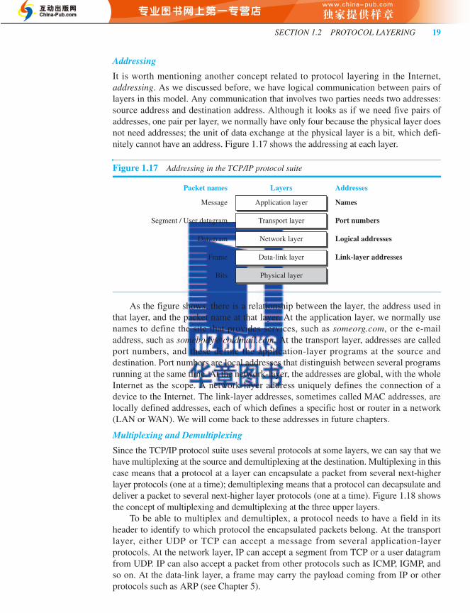
It is worth mentioning another concept related to protocol layering in the Internet,addressing. As we discussed before, we have logical communication between pairs oflayers in this model. Any communication that involves two parties needs two addresses:source address and destination address. Although it looks as if we need five pairs ofaddresses, one pair per layer, we normally have only four because the physical layer doesnot need addresses; the unit of data exchange at the physical layer is a bit, which defi-nitely cannot have an address. Figure 1.17 shows the addressing at each layer.
As the figure shows, there is a relationship between the layer, the address used inthat layer, and the packet name at that layer. At the application layer, we normally usenames to define the site that provides services, such as someorg.com, or the e-mailaddress, such as [email protected]. At the transport layer, addresses are calledport numbers, and these define the application-layer programs at the source anddestination. Port numbers are local addresses that distinguish between several programsrunning at the same time. At the network-layer, the addresses are global, with the wholeInternet as the scope. A network-layer address uniquely defines the connection of adevice to the Internet. The link-layer addresses, sometimes called MAC addresses, arelocally defined addresses, each of which defines a specific host or router in a network(LAN or WAN). We will come back to these addresses in future chapters.
Multiplexing and Demultiplexing
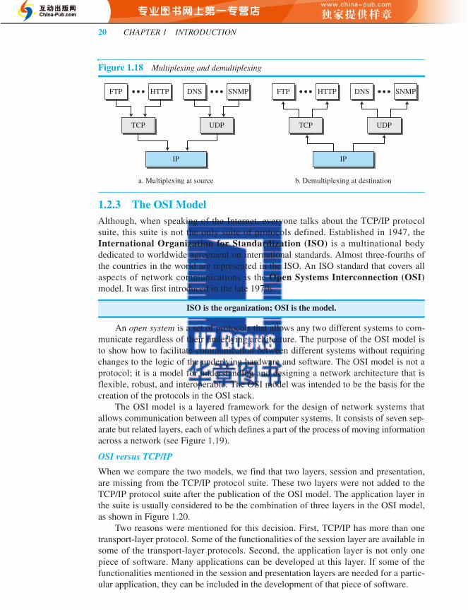
Since the TCP/IP protocol suite uses several protocols at some layers, we can say that wehave multiplexing at the source and demultiplexing at the destination. Multiplexing in thiscase means that a protocol at a layer can encapsulate a packet from several next-higherlayer protocols (one at a time); demultiplexing means that a protocol can decapsulate anddeliver a packet to several next-higher layer protocols (one at a time). Figure 1.18 showsthe concept of multiplexing and demultiplexing at the three upper layers.
To be able to multiplex and demultiplex, a protocol needs to have a field in itsheader to identify to which protocol the encapsulated packets belong. At the transportlayer, either UDP or TCP can accept a message from several application-layerprotocols. At the network layer, IP can accept a segment from TCP or a user datagramfrom UDP. IP can also accept a packet from other protocols such as ICMP, IGMP, andso on. At the data-link layer, a frame may carry the payload coming from IP or otherprotocols such as ARP (see Chapter 5).
Figure 1.17 Addressing in the TCP/IP protocol suite
Message
Segment / User datagram
Datagram
Frame
Bits
Link-layer addressesData-link layer
Physical layer
AddressesLayersPacket names
Port numbersTransport layer
NamesApplication layer
Network layer Logical addresses
for23267_ch01_001-032.fm Page 19 Monday, January 31, 2011 2:32 PM
20 CHAPTER 1 INTRODUCTION
1.2.3 The OSI ModelAlthough, when speaking of the Internet, everyone talks about the TCP/IP protocolsuite, this suite is not the only suite of protocols defined. Established in 1947, theInternational Organization for Standardization (ISO) is a multinational bodydedicated to worldwide agreement on international standards. Almost three-fourths ofthe countries in the world are represented in the ISO. An ISO standard that covers allaspects of network communications is the Open Systems Interconnection (OSI)model. It was first introduced in the late 1970s.
An open system is a set of protocols that allows any two different systems to com-municate regardless of their underlying architecture. The purpose of the OSI model isto show how to facilitate communication between different systems without requiringchanges to the logic of the underlying hardware and software. The OSI model is not aprotocol; it is a model for understanding and designing a network architecture that isflexible, robust, and interoperable. The OSI model was intended to be the basis for thecreation of the protocols in the OSI stack.
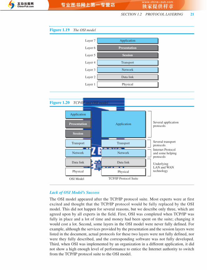
The OSI model is a layered framework for the design of network systems thatallows communication between all types of computer systems. It consists of seven sep-arate but related layers, each of which defines a part of the process of moving informationacross a network (see Figure 1.19).
OSI versus TCP/IP
When we compare the two models, we find that two layers, session and presentation,are missing from the TCP/IP protocol suite. These two layers were not added to theTCP/IP protocol suite after the publication of the OSI model. The application layer inthe suite is usually considered to be the combination of three layers in the OSI model,as shown in Figure 1.20.
Two reasons were mentioned for this decision. First, TCP/IP has more than onetransport-layer protocol. Some of the functionalities of the session layer are available insome of the transport-layer protocols. Second, the application layer is not only onepiece of software. Many applications can be developed at this layer. If some of thefunctionalities mentioned in the session and presentation layers are needed for a partic-ular application, they can be included in the development of that piece of software.
Figure 1.18 Multiplexing and demultiplexing
ISO is the organization; OSI is the model.
a. Multiplexing at source b. Demultiplexing at destination
SNMPDNS
TCP UDP
HTTPFTP
IP
SNMPDNS
TCP UDP
IP
HTTPFTP
for23267_ch01_001-032.fm Page 20 Monday, January 31, 2011 2:32 PM
SECTION 1.2 PROTOCOL LAYERING 21
Lack of OSI Model’s Success
The OSI model appeared after the TCP/IP protocol suite. Most experts were at firstexcited and thought that the TCP/IP protocol would be fully replaced by the OSImodel. This did not happen for several reasons, but we describe only three, which areagreed upon by all experts in the field. First, OSI was completed when TCP/IP wasfully in place and a lot of time and money had been spent on the suite; changing itwould cost a lot. Second, some layers in the OSI model were never fully defined. Forexample, although the services provided by the presentation and the session layers werelisted in the document, actual protocols for these two layers were not fully defined, norwere they fully described, and the corresponding software was not fully developed.Third, when OSI was implemented by an organization in a different application, it didnot show a high enough level of performance to entice the Internet authority to switchfrom the TCP/IP protocol suite to the OSI model.
Figure 1.19 The OSI model
Figure 1.20 TCP/IP and OSI model
Transport
Application
Presentation
Session
Network
Data link
PhysicalLayer 1
Layer 2
Layer 3
Layer 4
Layer 5
Layer 6
Layer 7
OSI Model TCP/IP Protocol Suite
UnderlyingLAN and WANtechnology
Internet Protocoland some helpingprotocols
Several transport protocols
Several applicationprotocols
Session
Presentation
Application
Application
Data link Data link
Network Network
Transport Transport
Physical Physical
for23267_ch01_001-032.fm Page 21 Monday, January 31, 2011 2:32 PM

22 CHAPTER 1 INTRODUCTION
1.3 INTERNET HISTORYNow that we have given an overview of the Internet and its protocol, let us give a briefhistory of the Internet. This brief history makes it clear how the Internet has evolvedfrom a private network to a global one in less than forty years.
1.3.1 Early HistoryThere were some communication networks, such as telegraph and telephone networks,before 1960. These networks were suitable for constant-rate communication at that time,which means that after a connection was made between two users, the encoded message(telegraphy) or voice (telephony) could be exchanged. A computer network, on the otherhand, should be able to handle bursty data, which means data received at variable rates atdifferent times. The world needed to wait for the packet-switched network to be invented.
Birth of Packet-Switched Networks
The theory of packet switching for bursty traffic was first presented by LeonardKleinrock in 1961 at MIT. At the same time, two other researchers, Paul Baran at RandInstitute and Donald Davies at National Physical Laboratory in England, publishedsome papers about packet-switched networks.
ARPANET
In the mid-1960s, mainframe computers in research organizations were stand-alonedevices. Computers from different manufacturers were unable to communicate withone another. The Advanced Research Projects Agency (ARPA) in the Department ofDefense (DOD) was interested in finding a way to connect computers so that theresearchers they funded could share their findings, thereby reducing costs and eliminat-ing duplication of effort.
In 1967, at an Association for Computing Machinery (ACM) meeting, ARPA pre-sented its ideas for Advanced Research Projects Agency Network (ARPANET), asmall network of connected computers. The idea was that each host computer (not nec-essarily from the same manufacturer) would be attached to a specialized computer,called an interface message processor (IMP). The IMPs, in turn, would be connected toeach other. Each IMP had to be able to communicate with other IMPs as well as with itsown attached host.
By 1969, ARPANET was a reality. Four nodes, at the University of California atLos Angeles (UCLA), the University of California at Santa Barbara (UCSB), StanfordResearch Institute (SRI), and the University of Utah, were connected via the IMPs toform a network. Software called the Network Control Protocol (NCP) provided com-munication between the hosts.
1.3.2 Birth of the Internet In 1972, Vint Cerf and Bob Kahn, both of whom were part of the core ARPANETgroup, collaborated on what they called the Internetting Project. They wanted to linkdissimilar networks so that a host on one network could communicate with a host onanother. There were many problems to overcome: diverse packet sizes, diverse inter-faces, and diverse transmission rates, as well as differing reliability requirements. Cerf
for23267_ch01_001-032.fm Page 22 Monday, January 31, 2011 2:32 PM

SECTION 1.3 INTERNET HISTORY 23
and Kahn devised the idea of a device called a gateway to serve as the intermediaryhardware to transfer data from one network to another.
TCP/IP
Cerf and Kahn’s landmark 1973 paper outlined the protocols to achieve end-to-enddelivery of data. This was a new version of NCP. This paper on transmission controlprotocol (TCP) included concepts such as encapsulation, the datagram, and the func-tions of a gateway. A radical idea was the transfer of responsibility for error correctionfrom the IMP to the host machine. This ARPA Internet now became the focus of thecommunication effort. Around this time, responsibility for the ARPANET was handedover to the Defense Communication Agency (DCA).
In October 1977, an internet consisting of three different networks (ARPANET,packet radio, and packet satellite) was successfully demonstrated. Communicationbetween networks was now possible.
Shortly thereafter, authorities made a decision to split TCP into two protocols: Trans-mission Control Protocol (TCP) and Internet Protocol (IP). IP would handle datagramrouting while TCP would be responsible for higher level functions such as segmentation,reassembly, and error detection. The new combination became known as TCP/IP.
In 1981, under a Defence Department contract, UC Berkeley modified the UNIXoperating system to include TCP/IP. This inclusion of network software along with apopular operating system did much for the popularity of networking. The open (non-manufacturer-specific) implementation of the Berkeley UNIX gave every manufacturera working code base on which they could build their products.
In 1983, authorities abolished the original ARPANET protocols, and TCP/IPbecame the official protocol for the ARPANET. Those who wanted to use the Internetto access a computer on a different network had to be running TCP/IP.
MILNET
In 1983, ARPANET split into two networks: Military Network (MILNET) for militaryusers and ARPANET for nonmilitary users.
CSNET
Another milestone in Internet history was the creation of CSNET in 1981. ComputerScience Network (CSNET) was a network sponsored by the National Science Founda-tion (NSF). The network was conceived by universities that were ineligible to join ARPA-NET due to an absence of ties to the Department of Defense. CSNET was a lessexpensive network; there were no redundant links and the transmission rate was slower.
By the mid-1980s, most U.S. universities with computer science departments werepart of CSNET. Other institutions and companies were also forming their own net-works and using TCP/IP to interconnect. The term Internet, originally associated withgovernment-funded connected networks, now referred to the connected networks usingTCP/IP protocols.
NSFNET
With the success of CSNET, the NSF in 1986 sponsored National Science FoundationNetwork (NSFNET), a backbone that connected five supercomputer centers locatedthroughout the United States. Community networks were allowed access to this
for23267_ch01_001-032.fm Page 23 Monday, January 31, 2011 2:32 PM
24 CHAPTER 1 INTRODUCTION
backbone, a T-1 line with a 1.544-Mbps data rate, thus providing connectivity throughoutthe United States. In 1990, ARPANET was officially retired and replaced by NSFNET.In 1995, NSFNET reverted back to its original concept of a research network.
ANSNET
In 1991, the U.S. government decided that NSFNET was not capable of supporting therapidly increasing Internet traffic. Three companies, IBM, Merit, and Verizon, filled thevoid by forming a nonprofit organization called Advanced Network & Services (ANS)to build a new, high-speed Internet backbone called Advanced Network ServicesNetwork (ANSNET).
1.3.3 Internet TodayToday, we witness a rapid growth both in the infrastructure and new applications. TheInternet today is a set of pier networks that provide services to the whole world. Whathas made the Internet so popular is the invention of new applications.
World Wide Web
The 1990s saw the explosion of Internet applications due to the emergence of the WorldWide Web (WWW). The Web was invented at CERN by Tim Berners-Lee. This inven-tion has added the commercial applications to the Internet.
Multimedia
Recent developments in the multimedia applications such as voice over IP (telephony),video over IP (Skype), view sharing (YouTube), and television over IP (PPLive) hasincreased the number of users and the amount of time each user spends on the network.We discuss multimedia in Chapter 8.
Peer-to-Peer Applications
Peer-to-peer networking is also a new area of communication with a lot of potential.We introduce some peer-to-peer applications in Chapter 2.
1.4 STANDARDS AND ADMINISTRATIONIn the discussion of the Internet and its protocol, we often see a reference to a standardor an administration entity. In this section, we introduce these standards and adminis-tration entities for those readers that are not familiar with them; the section can beskipped if the reader is familiar with them.
1.4.1 Internet StandardsAn Internet standard is a thoroughly tested specification that is useful to and adhered toby those who work with the Internet. It is a formalized regulation that must be followed.There is a strict procedure by which a specification attains Internet standard status. A spec-ification begins as an Internet draft. An Internet draft is a working document (a work inprogress) with no official status and a six-month lifetime. Upon recommendation from theInternet authorities, a draft may be published as a Request for Comment (RFC). EachRFC is edited, assigned a number, and made available to all interested parties. RFCs gothrough maturity levels and are categorized according to their requirement level.
for23267_ch01_001-032.fm Page 24 Monday, January 31, 2011 2:32 PM
SECTION 1.4 STANDARDS AND ADMINISTRATION 25
Maturity Levels
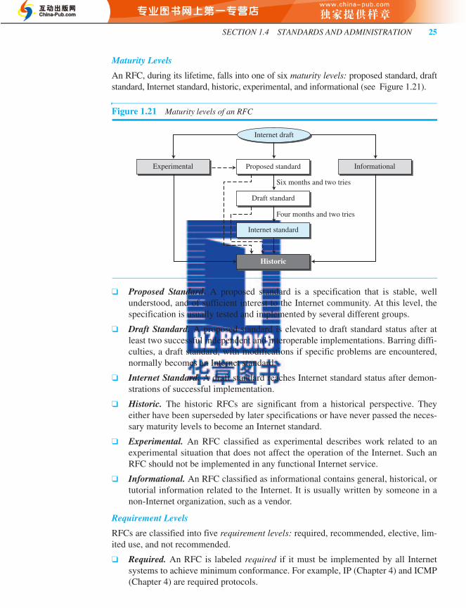
An RFC, during its lifetime, falls into one of six maturity levels: proposed standard, draftstandard, Internet standard, historic, experimental, and informational (see Figure 1.21).
❑ Proposed Standard. A proposed standard is a specification that is stable, wellunderstood, and of sufficient interest to the Internet community. At this level, thespecification is usually tested and implemented by several different groups.
❑ Draft Standard. A proposed standard is elevated to draft standard status after atleast two successful independent and interoperable implementations. Barring diffi-culties, a draft standard, with modifications if specific problems are encountered,normally becomes an Internet standard.
❑ Internet Standard. A draft standard reaches Internet standard status after demon-strations of successful implementation.
❑ Historic. The historic RFCs are significant from a historical perspective. Theyeither have been superseded by later specifications or have never passed the neces-sary maturity levels to become an Internet standard.
❑ Experimental. An RFC classified as experimental describes work related to anexperimental situation that does not affect the operation of the Internet. Such anRFC should not be implemented in any functional Internet service.
❑ Informational. An RFC classified as informational contains general, historical, ortutorial information related to the Internet. It is usually written by someone in anon-Internet organization, such as a vendor.
Requirement Levels
RFCs are classified into five requirement levels: required, recommended, elective, lim-ited use, and not recommended.
❑ Required. An RFC is labeled required if it must be implemented by all Internetsystems to achieve minimum conformance. For example, IP (Chapter 4) and ICMP(Chapter 4) are required protocols.
Figure 1.21 Maturity levels of an RFC
Proposed standardExperimental Informational
Draft standard
Six months and two tries
Four months and two tries
Internet standard
Historic
Internet draft
for23267_ch01_001-032.fm Page 25 Tuesday, February 1, 2011 5:09 PM

26 CHAPTER 1 INTRODUCTION
❑ Recommended. An RFC labeled recommended is not required for minimumconformance; it is recommended because of its usefulness. For example, FTP(Chapter 2) and TELNET (Chapter 2) are recommended protocols.
❑ Elective. An RFC labeled elective is not required and not recommended. However,a system can use it for its own benefit.
❑ Limited Use. An RFC labeled limited use should be used only in limited situations.Most of the experimental RFCs fall under this category.
❑ Not Recommended. An RFC labeled not recommended is inappropriate for gen-eral use. Normally a historic (deprecated) RFC may fall under this category.
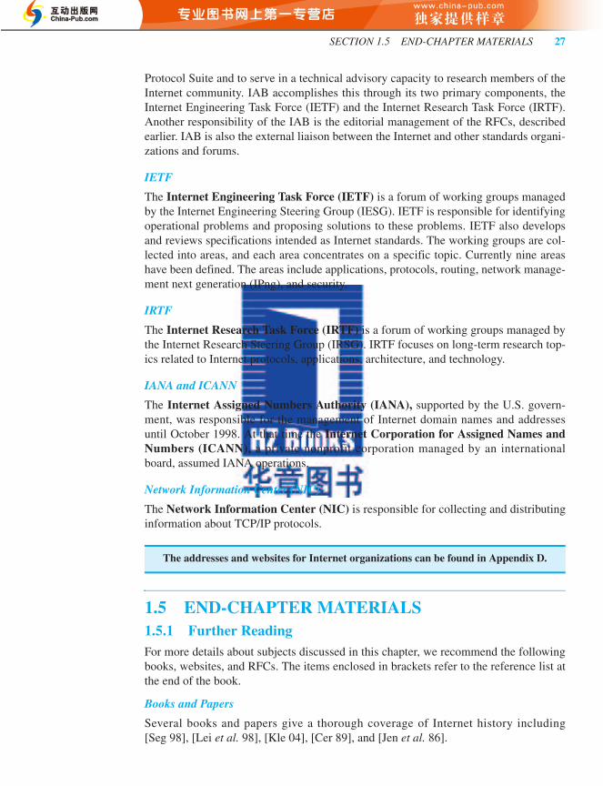
1.4.2 Internet AdministrationThe Internet, with its roots primarily in the research domain, has evolved and gaineda broader user base with significant commercial activity. Various groups that coordinateInternet issues have guided this growth and development. Appendix D gives the addresses,e-mail addresses, and telephone numbers for some of these groups. Figure 1.22shows the general organization of Internet administration.
ISOC
The Internet Society (ISOC) is an international, nonprofit organization formed in1992 to provide support for the Internet standards process. ISOC accomplishes thisthrough maintaining and supporting other Internet administrative bodies such as IAB,IETF, IRTF, and IANA (see the following sections). ISOC also promotes research andother scholarly activities relating to the Internet.
IAB
The Internet Architecture Board (IAB) is the technical advisor to the ISOC. Themain purposes of the IAB are to oversee the continuing development of the TCP/IP
RFCs can be found at http://www.rfc-editor.org.
Figure 1.22 Internet administration
IETFIRTF
RGRG RGRG
IESGIRSG
Area Area
WGWG WGWG
ISOC
IAB
for23267_ch01_001-032.fm Page 26 Monday, January 31, 2011 2:32 PM
SECTION 1.5 END-CHAPTER MATERIALS 27
Protocol Suite and to serve in a technical advisory capacity to research members of theInternet community. IAB accomplishes this through its two primary components, theInternet Engineering Task Force (IETF) and the Internet Research Task Force (IRTF).Another responsibility of the IAB is the editorial management of the RFCs, describedearlier. IAB is also the external liaison between the Internet and other standards organi-zations and forums.
IETF
The Internet Engineering Task Force (IETF) is a forum of working groups managedby the Internet Engineering Steering Group (IESG). IETF is responsible for identifyingoperational problems and proposing solutions to these problems. IETF also developsand reviews specifications intended as Internet standards. The working groups are col-lected into areas, and each area concentrates on a specific topic. Currently nine areashave been defined. The areas include applications, protocols, routing, network manage-ment next generation (IPng), and security.
IRTF
The Internet Research Task Force (IRTF) is a forum of working groups managed bythe Internet Research Steering Group (IRSG). IRTF focuses on long-term research top-ics related to Internet protocols, applications, architecture, and technology.
IANA and ICANN
The Internet Assigned Numbers Authority (IANA), supported by the U.S. govern-ment, was responsible for the management of Internet domain names and addressesuntil October 1998. At that time the Internet Corporation for Assigned Names andNumbers (ICANN), a private nonprofit corporation managed by an internationalboard, assumed IANA operations.
Network Information Center (NIC)
The Network Information Center (NIC) is responsible for collecting and distributinginformation about TCP/IP protocols.
1.5 END-CHAPTER MATERIALS1.5.1 Further ReadingFor more details about subjects discussed in this chapter, we recommend the followingbooks, websites, and RFCs. The items enclosed in brackets refer to the reference list atthe end of the book.
Books and Papers
Several books and papers give a thorough coverage of Internet history including[Seg 98], [Lei et al. 98], [Kle 04], [Cer 89], and [Jen et al. 86].
The addresses and websites for Internet organizations can be found in Appendix D.
for23267_ch01_001-032.fm Page 27 Monday, January 31, 2011 2:32 PM
28 CHAPTER 1 INTRODUCTION
RFCs
Two RFCs in particular discuss the TCP/IP suite: RFC 791 (IP) and RFC 817 (TCP). Infuture chapters we list different RFCs related to each protocol in each layer.
1.5.2 Key Terms
1.5.3 SummaryA network is a set of devices connected by communication links. A device can be a com-puter, printer, or any other device capable of sending and/or receiving data generated byother nodes on the network. Today when we speak of networks, we are generally refer-ring to two primary categories: local-area networks and wide-area networks. The Internettoday is made up of many wide and local area networks joined by connecting devices andswitching stations. Most end users who want Internet connection use the services ofInternet service providers (ISPs). There are backbone ISPs, regional ISPs, and local ISPs.
A protocol is a set of rules that governs communication. In protocol layering, weneed to follow two principles to provide bidirectional communication. First, each layerneeds to perform two opposite tasks. Second, two objects under each layer at both sidesshould be identical. TCP/IP is a hierarchical protocol suite made of five layers: applica-tion, transport, network, data-link, and physical.
The history of internetworking started with ARPA in the mid-1960s. The birth ofthe Internet can be associated with the work of Cerf and Kahn and the invention of agateway to connect networks. The Internet administration has evolved with the Internet.ISOC promotes research and activities. IAB is the technical advisor to the ISOC. IETFis a forum of working groups responsible for operational problems. IRTF is a forum ofworking groups focusing on long-term research topics. ICANN is responsible for themanagement of Internet domain names and addresses. NIC is responsible for collectingand distributing information about TCP/IP protocols.
An Internet standard is a thoroughly tested specification. An Internet draft is aworking document with no official status and a six-month lifetime. A draft may bepublished as a Request for Comment (RFC). RFCs go through maturity levels and arecategorized according to their requirement level.
Advanced Research Projects Agency (ARPA)
Advanced Network Services Network (ANSNET)
Advanced Research Projects Agency Network (ARPANET)
circuit-switched networkComputer Science Network (CSNET)International Organization for
Standardization (ISO)internetInternetInternet Architecture Board (IAB)Internet Assigned Numbers Authority
(IANA)Internet Corporation for Assigned Names
and Numbers (ICANN)
Internet Engineering Task Force (IETF)Internet Research Task Force (IRTF)Internet Service Provider (ISP)Internet Society (ISOC)internetworklocal area network (LAN)Military Network (MILNET)Network Information Center (NIC)National Science Foundation Network
(NSFNET)Open Systems Interconnection (OSI) modelpacket-switched networkprotocolprotocol layeringRequest for Comment (RFC)TCP/IP protocol suitewide area network (WAN)
for23267_ch01_001-032.fm Page 28 Monday, January 31, 2011 2:32 PM

SECTION 1.6 PRACTICE SET 29
1.6 PRACTICE SET1.6.1 QuizzesA set of interactive quizzes for this chapter can be found on the book website. It isstrongly recommended that the student take the quizzes to check his/her understandingof the materials before continuing with the practice set.
1.6.2 QuestionsQ1-1. Is transmission in a LAN with a common cable (Figure 1.1a) an example of
broadcast (one to many) transmission? Explain.
Q1-2. In a LAN with a link-layer switch (Figure 1.1b), Host 1 wants to send a mes-sage to Host 3. Since communication is through the link-layer switch, does theswitch need to have an address? Explain.
Q1-3. How many point-to-point WANs are needed to connect n LANs if each LANshould be able to directly communicate with any other LAN?
Q1-4. When we use local telephones to talk to a friend, are we using a circuit-switched network or a packet-switched network?
Q1-5. When a resident uses a dial-up or DLS service to connect to the Internet, whatis the role of the telephone company?
Q1-6. What is the first principle we discussed in this chapter for protocol layeringthat needs to be followed to make the communication bidirectional?
Q1-7. Which layers of the TCP/IP protocol suite are involved in a link-layer switch?
Q1-8. A router connects three links (networks). How many of each of the followinglayers can the router be involved with?
Q1-9. In the TCP/IP protocol suite, what are the identical objects at the sender andthe receiver sites when we think about the logical connection at the applicationlayer?
Q1-10. A host communicates with another host using the TCP/IP protocol suite. Whatis the unit of data sent or received at each of the following layers?
Q1-11. Which of the following data units is encapsulated in a frame?
Q1-12. Which of the following data units is decapsulated from a user datagram?
Q1-13. Which of the following data units has an application-layer message plus theheader from layer 4?
Q1-14. List some application-layer protocols mentioned in this chapter.
Q1-15. If a port number is 16 bits (2 bytes), what is the minimum header size at thetransport layer of the TCP/IP protocol suite?
a. physical layer b. data-link layer c. network layer
a. application layer b. network layer c. data-link layer
a. a user datagram b. a datagram c. a segment
a. a datagram b. a segment c. a message
a. a frame b. a user datagram c. a bit
for23267_ch01_001-032.fm Page 29 Monday, January 31, 2011 2:32 PM

30 CHAPTER 1 INTRODUCTION
Q1-16. What are the types of addresses (identifiers) used in each of the following layers?
Q1-17. When we say that the transport layer multiplexes and demultiplexes application-layer messages, do we mean that a transport-layer protocol can combineseveral messages from the application layer in one packet? Explain.
Q1-18. Can you explain why we did not mention multiplexing/demultiplexingservices for the application layer?
Q1-19. Assume we want to connect two isolated hosts together to let each host com-municate with the other. Do we need a link-layer switch between the two?Explain.
Q1-20. If there is a single path between the source host and the destination host, dowe need a router between the two hosts?
Q1-21. Explain the difference between an Internet draft and a proposed standard.
Q1-22. Explain the difference between a required RFC and a recommended RFC.
Q1-23. Explain the difference between the duties of the IETF and IRTF.
1.6.3 ProblemsP1-1. Answer the following questions about Figure 1.10 when the communication is
from Maria to Ann:
a. What is the service provided by layer 1 to layer 2 at Maria’s site?
b. What is the service provided by layer 1 to layer 2 at Ann’s site?
P1-2. Answer the following questions about Figure 1.10 when the communication isfrom Maria to Ann:
a. What is the service provided by layer 2 to layer 3 at Maria’s site?
b. What is the service provided by layer 2 to layer 3 at Ann’s site?
P1-3. Assume that the number of hosts connected to the Internet at year 2010 is fivehundred million. If the number of hosts increases only 20 percent per year,what is the number of hosts in year 2020?
P1-4. Assume a system uses five protocol layers. If the application program creates amessage of 100 bytes and each layer (including the fifth and the first) adds aheader of 10 bytes to the data unit, what is the efficiency (the ratio of application-layer bytes to the number of bytes transmitted) of the system?
P1-5. Assume we have created a packet-switched internet. Using the TCP/IP proto-col suite, we need to transfer a huge file. What is the advantage and disadvan-tage of sending large packets?
P1-6. Match the following to one or more layers of the TCP/IP protocol suite:
a. route determination
b. connection to transmission media
c. providing services for the end user
P1-7. Match the following to one or more layers of the TCP/IP protocol suite:
a. creating user datagrams
b. responsibility for handling frames between adjacent nodes
c. transforming bits to electromagnetic signals
a. application layer b. network layer c. data-link layer
for23267_ch01_001-032.fm Page 30 Monday, January 31, 2011 2:32 PM

SECTION 1.7 SIMULATION EXPERIMENTS 31
P1-8. In Figure 1.18, when the IP protocol decapsulates the transport-layer packet,how does it know to which upper-layer protocol (UDP or TCP) the packetshould be delivered?
P1-9. Assume a private internet uses three different protocols at the data-link layer(L1, L2, and L3). Redraw Figure 1.18 with this assumption. Can we say that,in the data-link layer, we have demultiplexing at the source node and multi-plexing at the destination node?
P1-10. Assume that a private internet requires that the messages at the applicationlayer be encrypted and decrypted for security purposes. If we need to add someinformation about the encryption/decryption process (such as the algorithmsused in the process), does it mean that we are adding one layer to the TCP/IPprotocol suite? Redraw the TCP/IP layers (Figure 1.12 part b) if you think so.
P1-11. Protocol layering can be found in many aspects of our lives such as air travel-ling. Imagine you make a round-trip to spend some time on vacation at aresort. You need to go through some processes at your city airport before fly-ing. You also need to go through some processes when you arrive at the resortairport. Show the protocol layering for the round trip using some layers suchas baggage checking/claiming, boarding/unboarding, takeoff/landing.
P1-12. In Figure 1.4 in the text, there is only a single path from a host at the westcoast office to a host at the east coast office. Why do we need two routers inthis internetwork?
P1-13. The presentation of data is becoming more and more important in today’sInternet. Some people argue that the TCP/IP protocol suite needs to add a newlayer to take care of the presentation of data (see Appendix C). If this newlayer is added in the future, where should its position be in the suite? RedrawFigure 1.12 to include this layer.
P1-14. In an internet, we change the LAN technology to a new one. Which layers inthe TCP/IP protocol suite need to be changed?
P1-15. Assume that an application-layer protocol is written to use the services ofUDP. Can the application-layer protocol uses the services of TCP withoutchange?
P1-16. Using the internet in Figure 1.4 in the text, show the layers of the TCP/IP pro-tocol suite and the flow of data when two hosts, one on the west coast and theother on the east coast, exchange messages.
1.7 SIMULATION EXPERIMENTS1.7.1 AppletsOne of the ways to show the network protocols in action or visually see the solution tosome examples is through the use of interactive animation. We have created some Javaapplets to show some of the main concepts discussed in this chapter. It is strongly rec-ommended that the students activate these applets on the book website and carefullyexamine the protocols in action.
for23267_ch01_001-032.fm Page 31 Monday, January 31, 2011 2:32 PM
32 CHAPTER 1 INTRODUCTION
1.7.2 Lab AssignmentsExperiments with networks and network equipment can be done using at least twomethods. In the first method, we can create an isolated networking laboratory and usenetworking hardware and software to simulate the topics discussed in each chapter. Wecan create an internet and send and receive packets from any host to another. The flowof packets can be observed and the performance can be measured. Although thismethod is more effective and more instructional than the second method, it is expensiveto implement and not all institutions are ready to invest in such an exclusive laboratory.
In the second method, we can use the Internet, the largest network in the world, asour virtual laboratory. We can send and receive packets using the Internet. The exis-tence of some free, downloadable software allows us to capture and examine the pack-ets exchanged. We can analyze the packets to see how theoretical aspects of networkingare put into action. Although the second method may not be as effective as the firstmethod, in that we cannot control and change the packet routes to see how the Internetbehaves, the method is much cheaper to implement. It does not need a physical net-working lab; it can be implemented using our desktop or laptop. The required softwareis also free to download.
There are many programs and utilities available for Windows and UNIX operatingsystems that allow us to sniff, capture, trace, and analyze packets that are exchangedbetween our computer and the Internet. Some of these, such as Wireshark and PingPlotter have graphical user interface (GUI); others, such as traceroute, nslookup, dig,ipconfig, and ifconfig, are network administration command-line utilities. Any of theseprograms and utilities can be a valuable debugging tool for network administrators andan educational tool for computer network students.
In this book, we mostly use Wireshark for lab assignments, although we occasion-ally use other tools. Wireshark captures live packet data from a network interface anddisplays them with detailed protocol information. Wireshark, however, is a passiveanalyzer. It only “measures” things from the network without manipulating them; itdoesn’t send packets on the network or do other active operations. Wireshark is not anintrusion detection tool either. It does not give warning about any network intrusion. It,nevertheless, can help network administrators or network security engineers figure outwhat is going on inside a network and to troubleshoot network problems. In addition tobeing an indispensable tool for network administrators and security engineers, Wiresharkis a valuable tool for protocol developers, who may use it to debug protocol implemen-tations, and a great educational tool for computer networking students who can use it tosee details of protocol operations in real time.
In this lab assignment, we learn how to download and install Wireshark. Theinstructions for downloading and installing the software are posted on the book websitein the lab section for Chapter 1. In this document, we also discuss the general ideabehind the software, the format of its window, and how to use it. The full study of thislab prepares the student to use Wireshark in the lab assignments for the next chapter.
for23267_ch01_001-032.fm Page 32 Tuesday, February 1, 2011 5:19 PM


