FOR THE CLASSIFICATION OF SHIPS - crs.hr for the... · 7.7 VENTILATION OF CARGO SPACES ADAPTED FOR...
80
RULES FOR THE CLASSIFICATION OF SHIPS Part 8 - PIPING 2013 CROATIAN REGISTER OF SHIPPING Hrvatska (Croatia) • 21000 Split • Marasovićeva 67 • P.O.B. 187 Tel.: (...) 385 (0)21 40 81 11 Fax.: (...) 385 (0)21 35 81 59 E-mail: [email protected] web site: www.crs.hr
Transcript of FOR THE CLASSIFICATION OF SHIPS - crs.hr for the... · 7.7 VENTILATION OF CARGO SPACES ADAPTED FOR...
RULESFOR THE CLASSIFICATION OF SHIPS
Part 8 - PIPING
2013
CROATIAN REGISTER OF SHIPPING
Hrvatska (Croatia) • 21000 Split • Marasovićeva 67 • P.O.B. 187Tel.: (...) 385 (0)21 40 81 11Fax.: (...) 385 (0)21 35 81 59
E-mail: [email protected] site: www.crs.hr

By decision of the General Committee of Croatian Register of Shipping,
RULES FOR THE CLASSIFICATION OF SHIPSPART 8 – PIPING
has been adopted on 28th December 2012 and shall enter into force on 1st January 2013

RULES FOR THE CLASSIFICATION OF SHIPSPART 8
2013
REVIEW OF AMENDMENTS IN RELATION TO PREVIOUSEDITION OF THE RULES
RULES FOR THE CLASSIFICATION OF SHIPSPart 8 - Piping
All major changes throughout the text in respect to the Rules for technical supervision of sea-goingships, Part 8 – Piping, 2009 edition are shaded.
Items not being indicated as corrected have not been changed.
The grammatical and print errors, have also been corrected throughout the text of the subject Rules butare not indicated as a correction.

RULES FOR THE CLASSIFICATION OF SHIPSPART 8
2013
The subject Rules include the requirements of the following international Organisations:
International Maritime Organization (IMO)Conventions: International Convention for the Safety of Life at Sea 1974 (SOLAS 1974) and all subsequent
amendments up to and including the 2008 amendments (MSC.256(84)Protocol of 1988 relating to the International Convention for the Safety of Life at Sea 1974, asamended (SOLAS PROT 1988)
International Convention on Load Lines, 1966, as modified by the 1988 Protocol relating theretoand all amendments up to and including 2003 amendments adopted by resolution MSC.143 (77)
International Association of Classification Societies (IACS)
Unified Requirements (UR): E8 (1996), F2 (1999), F8 (1989), F15 (1996), F16 (2000),F21 (1974), F22 (1974), F24 (1998), F26 (2000), F33 (1981), F35 (2005), F39 (1999),F41 (1993), F44 (2010), M11 (1972), M24 (1976), M45 (2011), M57 (1993), M61 (2003), M64(2004), M65 (2004), P1 (2001), P2 (2007), P2.12.5 (Aug 2007), P2.11 (2012),P3 (2004), P4 (2008)
Unified Interpretations: SC56, SC57, SC58, SC 64 (2005), SC89 (2011), SC99 (2005), SC111 (1995), SC118,SC123 (2005), SC140 (1998), SC179 (2011), SC 232 (2009), SC 243 (2012, SC251 (2011),SC 255 (2012), LL10 (2008), LL11 (2008), LL36 (2008), LL49 (2008), LL52 (2008),LL58 (2008),
Unified recommendations: REC 100,
RULES FOR THE CLASSIFICATION OF SHIPSPART 8
2013
ContentsPage
1 GENERAL............................................................................................................................................................. 11.1 APPLICATION..........................................................................................................................................................................11.2 SCOPE OF SUPERVISION.......................................................................................................................................................11.3 PIPELINES ................................................................................................................................................................................31.4 PIPE VALVES AND FITTINGS ...............................................................................................................................................151.5 SEA WATER INLET BOXES, ICE BOXES,OPENINGS IN SHELL PLATING AND BOTTOM AND SIDE
FITTINGS ..................................................................................................................................................................................161.6 LEADING OF PIPELINES........................................................................................................................................................181.7 APPLICATION OF PLASTIC PIPES ON SHIPS .....................................................................................................................211.8 FLOW VELOCITY IN PIPING SYSTEMS ..............................................................................................................................271.9 MACHINERY AND AUTOMATED INSTALLATIONS ........................................................................................................30
2 BILGE SYSTEM................................................................................................................................................... 312.1 PUMPS.......................................................................................................................................................................................312.2 PIPE DIAMETERS ....................................................................................................................................................................322.3 PIPING ARRANGEMENT........................................................................................................................................................322.4 DRAINAGE OF MACHINERY SPACES.................................................................................................................................332.5 DRAINAGE OF TUNNELS ......................................................................................................................................................332.6 DRAINAGE OF CARGO HOLDS ............................................................................................................................................342.7 DRAINAGE OF REFRIGERATED CARGO SPACES ............................................................................................................342.8 DRAINAGE OF DEEP TANKS ................................................................................................................................................342.9 DRAINAGE OF COFFERDAMS..............................................................................................................................................352.10 DRAINAGE OF FORE AND AFTER PEAK............................................................................................................................352.11 DRAINAGE OF OTHER SPACES............................................................................................................................................352.12 SPECIFIC REQUIREMENTS FOR DRAINAGE OF FORWARD SPACES IN BULK, ORE AND COMBINATION
CARRIERS ("dewatering system") ............................................................................................................................................35
3 BALLAST SYSTEM............................................................................................................................................. 373.1 PUMPS.......................................................................................................................................................................................373.2 PIPE DIAMETERS ....................................................................................................................................................................373.3 PIPING ARRANGEMENT........................................................................................................................................................37
4 CARGO PIPING SYSTEM OF OIL TANKERS AND OIL COLLECTING SHIPS.................................... 384.1 PUMPS AND THEIR DRIVES .................................................................................................................................................384.2 PIPING ARRANGEMENT........................................................................................................................................................384.3 OIL COLLECTING SYSTEM IN OIL COLLECTING SHIPS.................................................................................................394.4 FORE AND AFT CARGO LOADING AND UNLOADING PIPING SYSTEM IN TANKERS .............................................394.5 INTEGRATED CARGO AND BALLAST SYSTEMS ON TANKERS ...................................................................................40
5 AIR,GAS VENT, OVERFLOW AND SOUNDING SYSTEMS....................................................................... 415.1 AIR PIPES..................................................................................................................................................................................415.2 CARGO TANK VENTING, PURGING AND GAS-FREEING................................................................................................425.3 OVERFLOW PIPES...................................................................................................................................................................455.4 OVERFLOW TANKS................................................................................................................................................................455.5 SOUNDING ARRANGEMENTS..............................................................................................................................................45
6 EXHAUST GAS SYSTEM................................................................................................................................... 476.1 EXHAUST GAS PIPES .............................................................................................................................................................476.2 SILENCERS AND SPARK ARRESTERS ................................................................................................................................47
7 VENTILATION SYSTEM................................................................................................................................... 487.1 VENTILATION DUCTS ...........................................................................................................................................................487.2 VENTILATION OF CARGO SHIPS OF 500 TONS GROSS TONNAGE AND UPWARDS, PASSENGER SHIPS
CARRYING NOT MORE THAN 36 PASSENGERS AND SPECIAL PURPOSE SHIPS CARRYING NOT MORETHAN 200PERSONS IN ADDITION TO CREW MEMBERS ................................................................................................48
7.3 VENTILATION OF PASSENGER SHIPS CARRYING MORE THAN 36 PASSENGERS AND SPECIAL PURPOSESHIPS CARRYING MORE THAN 200 PERSONS IN ADDITION TO CREW MEMBERS..................................................49
RULES FOR THE TECHNICAL SUPERVISION OF SHIPSPART 8
2013
7.4 VENTILATION OF TANKERS AND COMBINATION CARRIERS..................................................................................... 507.5 VENTILATION OF MACHINERY SPACES AND TUNNELS .......................................................................................... 507.6 VENTILATION OF SPECIAL CATEGORY SPACES, CARGO SPACES INTENDED FOR CARRIAGE OF
MOTOR VEHICLES WITH FUEL IN THEIR TANKS AND CLOSED RO-RO CARGO SPACES.................................. 517.7 VENTILATION OF CARGO SPACES ADAPTED FOR CARRIAGE OF DANGEROUS GOODS.................................. 517.8 VENTILATION OF REFRIGERATED SPACES................................................................................................................. 527.9 VENTILATION OF FOAM FIRE-EXTINGUISHING AND SMOTHERING STATIONS ................................................ 527.10 VENTILATION OF ACCUMULATOR BATTERY ROOMS AND BOXES...................................................................... 527.11 VENTILATION OF HANGARS FOR HELICOPTERS....................................................................................................... 527.12 VENTILATION OF RADIO ROOM..................................................................................................................................... 527.13 VENTILATION OF OIL COLLECTING SHIPS.................................................................................................................. 537.14 VENTILATION OF SPACES WITH INERT GAS SYSTEM DEVICES ............................................................................ 53
8 FUEL OIL SYSTEM.......................................................................................................................................... 548.1 PUMPS................................................................................................................................................................................... 548.2 PIPING ARRANGEMENT.................................................................................................................................................... 548.3 ARRANGEMENTS FOR HEATING OF FUEL OIL IN TANKS ........................................................................................ 548.4 DRAINAGE ARRANGEMENTS OF FUEL OIL TANKS................................................................................................... 548.5 ARRANGEMENTS FOR COLLECTION OF LEAKAGE FUEL ........................................................................................ 558.6 FILLING OF FUEL OIL TANKS.......................................................................................................................................... 558.7 FUEL OIL TANKS................................................................................................................................................................ 558.8 FUEL OIL SUPPLY SYSTEM OF INTERNAL COMBUSTION ENGINES ...................................................................... 568.9 FUEL OIL SYSTEM OF BOILERS...................................................................................................................................... 568.10 FUEL OIL SUPPLY TO GAS TURBINES........................................................................................................................... 568.11 USAGE OF CRUDE OIL AND CARGO RESIDUES AS FUEL FOR BOILERS ............................................................... 578.12 FUEL PUMP ARRANGEMENT ON SHIPS OPERATING IN EMISSION CONTROL AREAS....................................... 58
9 LUBRICATING OIL SYSTEM........................................................................................................................ 609.1 LUBRICATING OIL PUMPS OF INTERNAL COMBUSTION ENGINES, GEARS AND COUPLINGS........................ 609.2 LUBRICATING OIL SUPPLY SYSTEM OF INTERNAL COMBUSTION ENGINES AND GEARS.............................. 609.3 LUBRICATING OIL PUMPS OF STEAM TURBINES....................................................................................................... 609.4 LUBRICATING OIL SUPPLY SYSTEM OF STEAM TURBINES AND GEARS............................................................. 619.5 LUBRICATING OIL TANKS ............................................................................................................................................... 619.6 ARRANGEMENTS FOR COLLECTION OF LEAKAGE OIL ........................................................................................... 619.7 LUBRICATING OIL SYSTEM OF GAS TURBINE............................................................................................................ 61
10 COOLING WATER SYSTEM ......................................................................................................................... 6210.1 PUMPS................................................................................................................................................................................... 6210.2 PIPING ARRANGEMENT.................................................................................................................................................... 6210.3 COOLING WATER FILTERS .............................................................................................................................................. 6310.4 COOLING OF INTERNAL COMBUSTION ENGINES ...................................................................................................... 6310.5 COOLING OF GAS TURBINE SYSTEMS.......................................................................................................................... 63
11 COMPRESSED AIR SYSTEM ........................................................................................................................ 6411.1 NUMBER AND CAPACITY OF STARTING AIR RECEIVERS........................................................................................ 6411.2 COMPRESSORS ................................................................................................................................................................... 6411.3 PIPING ARRANGEMENT.................................................................................................................................................... 65
12 FEED WATER SYSTEM.................................................................................................................................. 6612.1 PUMPS................................................................................................................................................................................... 6612.2 PIPING ARRANGEMENT.................................................................................................................................................... 6612.3 TANKS .................................................................................................................................................................................. 66
13 STEAM AND BLOW-OFF SYSTEMS............................................................................................................ 6713.1 PIPING ARRANGEMENT.................................................................................................................................................... 6713.2 BLOW-OFF ARRANGEMENTS OF STEAM LINES ......................................................................................................... 6713.3 CALCULATION OF THERMAL EXPANSION OF STEAM PIPES .................................................................................. 67
14 CONDENSER SYSTEM.................................................................................................................................... 6914.1 GENERAL ............................................................................................................................................................................. 6914.2 PUMPS................................................................................................................................................................................... 6914.3 PIPING ARRANGEMENTS ................................................................................................................................................. 6914.4 INSTRUMENTATION.......................................................................................................................................................... 69
RULES FOR THE CLASSIFICATION OF SHIPSPART 8
2013
15 SYSTEMS WITH THERMAL FLUIDS BASED ON MINERAL OILS...................................................... 7015.1 PUMPS ...................................................................................................................................................................................7015.2 EXPANSION TANKS............................................................................................................................................................7015.3 OIL STORAGE TANKS ........................................................................................................................................................7015.4 LAYOUT OF PIPES ..............................................................................................................................................................7015.5 VENT PIPES ..........................................................................................................................................................................7015.6 ARRANGEMENTS FOR COLLECTION OF THERMAL OIL LEAKAGE AND ITS DISCHARGE................................7015.7 COOLING OF THERMAL OIL.............................................................................................................................................7015.8 BOILERS FOR HEATING OF THERMAL OILS.................................................................................................................7015.9 INSULATION ........................................................................................................................................................................7015.10 HEATING OF LIQUID CARGO ...........................................................................................................................................7015.11 TESTS OF PIPING IN THERMAL OIL SYSTEMS .............................................................................................................70
16 SCUPPERS, INLETS AND DISCHARGES.................................................................................................... 7116.1 SCUPPERS AND DISCHARGES .........................................................................................................................................7116.2 SCUPPER AND DISCHARGE PIPES...................................................................................................................................71
17 HYDRAULIC TESTS........................................................................................................................................ 7317.1 HYDRAULIC TESTS OF VALVES AND FITTINGS..........................................................................................................7317.2 HYDRAULIC TESTINGS OF PIPING .................................................................................................................................73
RULES FOR THE CLASSIFICATION OF SHIPS 1PART 8
2013
1 GENERAL
1.1 APPLICATION
1.1.1 The requirements of the present Part of theRules for the Classification of Ships (hereafter called: Rules)apply to the pipelines in following systems:
.1 liquid cargo (oil, toxic media, liquefiedgas);
.2 tank cleaning and washing;
.3 gas welding and cutting;
.4 refrigerating (refrigerant - freon, ammonia,brine);
.5 ventilation;
.6 sanitary and drinking water;
.7 sanitary discharges and sewage treatmentplant;
.8 fuel oil;
.9 lubricating oil;
.10 cooling (with fresh water, sea water, oil);
.11 exhaust gas;
.12 compressed air;
.13 steam and condensate;
.14 feed water;
.15 bilge;
.16 ballast;
.17 drains from weather decks;
.18 fire extinguishing (by water, gas, foam,dry powder);
.19 air, sounding, filing and overflow pipes;
.20 hydraulic and hydraulic drives;
.21 thermal fluids based on mineral oils.The requirements for the systems that were not
mentioned above are set out in the relevant Parts of the Rules.
1.1.2 Oil fuel used in ships shall be in compliancewith requirements of Rules, Part 7 - Machinery Installations,1.1.2.
1.1.3 Machinery and other elements of piping systemsstated in 1.1.1 shall ensure their reliable operation under envi-ronmental conditions according to requirements stated inRules, Part 7 - Machinery Installations, 1.6.
1.1.4 Definitions and explanations relating to generalterminology of the Rules, Part 1- General Rules, Chapter 4.
Unless otherwise specified, following defini-tions and explanations shall apply to this Part of the Rules:
.1 Piping and piping systemsPiping includes pipes and their connec-tions, flexible hoses and expansion joints,valves and their actuating systems, otheraccessories (filters, level gauges, etc.) andpump casings.Piping systems include piping and all theinterfacing equipment such as tanks, pres-sure vessels, heat exchangers, pumps andcentrifugal purifiers, but do not includeboilers, turbines, internal combustion en-gines and reduction gears.
.2 Design pressure of a piping system is thepressure considered by the manufacturer todetermine the scantling of the systemcomponents. It is not to be taken less thanthe maximum working pressure expectedin this system or the highest setting pres-sure of any safety valve or relief device,whichever is the greater.For power piping for hydraulic steeringgears, the design pressure is not to be lessthan 1,25 times the maximum workingpressure, or the highest setting pressure ofany safety valve or relief device, which-ever is the greater.For a boiler feed system, the design pres-sure is not to be less than 1,25 times thedesign pressure of the boiler or the maxi-mum pressure expected in the feed piping,whichever is the greater.For steam piping located upstream of pres-sure reducing valves (high pressure side),the design pressure is not to be less thanthe setting pressure of the boiler or super-heater safety valves.For piping system located on the low pres-sure side of a pressure reducing valvewhere no safety valve is provided, the de-sign pressure is not to be less than themaximum pressure on the high pressureside of the pressure reducing valve.For piping system located on the deliveryside of a pump or a compressor, the designpressure is not to be less than the settingpressure of the safety valve for displace-ment pumps or the maximum pressure re-sulting from the operating (head-capacity)curve for centrifugal pumps, whichever isthe greater.
.3 Design temperature of a piping system isthe maximum temperature of the mediuminside the system.
.4 Flammable oils include fuel oils, lubri-cating oils, thermal oils and hydraulic oils.
Other definitions and explanations for the purpose ofthis Part of the Rules, have been adopted as listed in Part 7 –Machinery Installation, Part 9 – Machines, Part 10 – Boilers,Heat Exchangers and Pressure Vessels, Part 11 – Refrigerat-ing Plant and other referent Rules.
1.2 SCOPE OF SUPERVISION
1.2.1 General provisions relating to the classificationprocedure, supervision during construction and testings aswell as requirements for technical documentation to be sub-mitted to the CROATIAN REGISTER OF SHIPPING(hereinafter called: Register) for consideration and approvalare set forth in the Rules, Part 1 - General requirements andRules for Classification of Ships.
1.2.2 For purpose of testing, selection of joint typesand heat treatment, depending on intended service and work-ing media characteristics, piping systems are subdivided intoclasses (see Figure 1.2.2 and Table 1.2.2).

2 RULES FOR THE CLASSIFICATION OF SHIPSPART 8
2013
1.2.3 Pipes, valves and fittings of Class I and Class II,as well as the valves and fittings on the collision bulkhead, onship's sides and bottom, and distance controlled valves are
subject to supervision by the Register in the course of manu-facture.
(P = design pressure; T = design temperature)
Figure 1.2.2
Table 1.2.2
Piping system for Class IP > or T > Class II Class III
P ≤ and T ≤
Toxic or corrosive media Without specialsafeguards
With specialsafeguards (1,2)
Not applicable
Flammable media heated above flash pointor with flash point blow 60°C
Liquefied Gas
Without specialsafeguards
With specialsafeguards (1) Not applicable
Steam 1,6 300 0,7 170
Thermal Oil 1,6 300 0,7 150
Fuel OilLubricating Oil
Flammable Hydraulic Oil1,6 150
Any pressure-temperature combina-tion not belonging to
Class I or III 0,7 60
Other Media (5,6) 4,0 300 1,6 200
Notes:1) Safeguards for reducing leakage possibility and limiting its consequences: e.g. pipes led in positions where
leakage of internal fluids will not cause a potentioal hazard or damage to surrounding areas which may includethe use of pipe ducts, shielding, screening etc.
2) Class II pipes are not to be used for toxic media.3) Cargo oil pipes belong to Class III.4) P = Design pressure [ MPa ]; T = Design temperature [°C], (see 1.3.4.1).5) Including water, air, gases, non-flammable hydraulic oil6) Open ended pipes (drains, overflows, vents, exhaust gas lines, boiler escape pipes) irrespective of the tempera-
ture, Class III pipes may be used.
Class I
P1
P2
P
T2T1 T
Class II
Class III

RULES FOR THE CLASSIFICATION OF SHIPS 3PART 8
2013
1.3 PIPELINES
1.3.1 Materials, manufacture and application
1.3.1.1 Materials used for manufacture of pipes, valvesand fittings shall comply with the requirements of the RulesPart 25 – Metallic Materials.
Materials for pipes, valves and fittings intendedfor aggressive corrosive media, will be considered by theRegister in each particular case.
1.3.l.2 Steel pipes for piping systems of Classes I and IIshall be seamless pipes, or pipes fabricated with a weldingprocedure, considered by the Register to be equivalent toseamless pipes. In general, pipes, valves and fittings of carbonsteel and carbon manganese steel shall be used for tempera-tures not exceeding 400oC, and these of low-alloy steel fortemperatures not exceeding 500oC.
These steels may be admitted for temperatureshigher than the above mentioned, if their mechanical proper-ties and the average stress to produce rupture (i.e. tensilestrength after 100000 hours at the design temperature) complywith the effective standards and are guaranteed by the steelmaker as suitable for high temperature service.
Pipes, valves and fittings for media with tem-perature above 500oC shall be manufactured of alloy steel.Exhaust gas pipes are excluded from this requirement.
1.3.1.3 Copper and copper alloy pipes shall be seamlessor fabricated by other procedure approved by the Register.
Copper pipes for Classes I and II shall be seam-less.
Copper and copper alloy pipes, valves and fit-tings, in general, shall not be used for temperatures exceeding200oC, and copper-nickel alloy piping for temperatures ex-ceeding 300oC (see Table 1.3.4.1-3). Bronze valves and fit-tings shall not be used for temperatures exceeding 260oC.
1.3.1.4 Nodular graphite cast iron may be accepted forbilge, ballast and cargo oil pipes, valves and fittings.
The use of these pipes, valves and fittings onother places as well as for other services in general in ClassesII and III, will be separately considered by the Register.
Nodular graphite cast iron valves and fittingsshall not be accepted for media with temperatures exceeding350oC.
Valves and fittings for ship side, bottom andbelowe the bulkhead, as well as valves and fittings at fuel oiland lubricating oil tank collision bulkheads, may be manu-factured of nodular graphite cast iron in accordance with theRules, Part 25 – Metallic Materials, Table 3.13.3.3.
1.3.1.5 Grey cast iron valves and fittings may be ac-cepted for cargo oil lines within cargo tanks of tankers.
Grey cast iron valves and fittings may be alsoused for open deck cargo lines with pressure below 1,6 MPaexcept for the valves and fittings of cargo piping for connec-tion to the cargo loading and discharge hoses.
Grey cast iron pipes, valves and fittings for otherservice of Class III shall be separately considered by the Reg-ister.
Grey cast iron shall not be used for:.1 piping handling media having temperature
above 220oC;.2 piping subject to water hammer, excessive
strains and vibrations;.3 piping installed directly on outside plating;.4 piping installed on ship's hull shell plating
and collision bulkhead;.5 piping installed directly on lubricating and
fuel oil tanks exposed to hydrostatic pres-sure.
1.3.1.6 Lead pipes shall not be fitted in positions wherethey may cause the risk of flooding, if damaged.
1.3.1.7 Plastic pipes may be admitted in shipboard pip-ing systems. The use will be considered in relation to the in-tended service, the location, the operating conditions, andproperties of the material, in accordance with requirementslisted in Head number 1.7.
Documentation with important details shall besubmitted for approval. For Class I, Class II and any Class IIIin essential services (for which there are Rule requirements),the pipes, valves and their associated fittings shall be ap-proved by Register.
1.3.1.8 Type and design of flexible joints used withinthe systems specified in 1.1.1 shall be approved for the serviceconditions and the intended application. Type approval shallinclude relevant type testing in accordance within the IACSUR P2.12.5, following the applicable recognised standard.
The use of flexible joints is permitted as readysleeves with connecting parts (flanges or screw joints).
These joints shall be situated in conspicuous andreadily accessible places, and shall be capable of being sepa-rated from fuel oil, lubricating oil, compressed air and coolingwater systems by means of valves, so that, in a case of dam-age, flexible joint can be replaced without stopping of othermachinery.
If flexible joints, are used in piping supervisedby the Register, the ship shall be supplied with spare flexiblejoints, one for each type and size.
Flexible joints shall be fire-resistant, if they areused in:
− pipes conveying fuel or lubricating oil;− pipes supplying working medium to drives
of watertight doors;− pipes connected with openings in shell plat-
ing;− pipes for other flammable oil products;− pipes where damage to the joint may be a
danger to the ship or persons on board:Flexible joints are considered fire resistant when
connected to pipe line filled with water, after being subjectedto fire for 30 minutes at a temperature of 800oC while water atthe maximum service pressure is circulated inside the pipe andtemperature at the outlets shall not be less than 80oC, still re-main watertight.
Flexible pipes of the approved type are admittedin hydraulic systems of steering gear, where connections arerequired to be flexible.

4 RULES FOR THE CLASSIFICATION OF SHIPSPART 8
2013
Material for hoses shall be chosen taking intoaccount the fluid used, pressures, temperatures and environ-mental conditions.
Breaking pressure shall be at least 4 times thedesigned pressure. Length of pipes is to provide flexibility ofconnections and normal operation of machinery.
1.3.1.9 Plugs and threaded parts of sounding pipes onopen decks shall be of bronze or brass. Use of other materialsshall be separately considered by the Register in each par-ticular case.
1.3.1.10 Self-closing fittings of sounding pipes of dou-ble-bottom fuel tanks shall be corrosion resistant and so de-signed as to exclude spark formation.
1.3.2 Radii of pipe bends
1.3.2.1 Inner radius of bend of steel and copper pipessubjected to a pressure exceeding 0,5 MPa or temperaturesabove 60oC, as well as bending radius of pipes with allowancefor thermal expansion shall be at least 2,5 d (d = pipe outsidediameter). If, in process of bending, no thinning of the pipewall is observed, the specified radius may be reduced.
1.3.2.2 Radius of bend of pipes operating under condi-tions other than those specified above may be reduced up to1,5 d, provided machine bending is applied.
1.3.2.3 Inner radius of bend of boiler blow off pipesshall be at least 3,5 d (d = pipe inside diameter).
1.3.2.4 Radius of bend in 1.3.2.1, 1.3.2.2 and 1.3.2.3means the inner, i.e. the least radius of pipe curvature afterbending.
1.3.3 Heat treatment of pipes after bending
1.3.3.1 Steel pipes, in general, shall be subjected tobending at the temperature of 850-1000oC with possibility oftemperature reduction in the course of bending process to750oC.
Pipes subjected to bending at the temperaturesdefined as above shall be treated as follows:
.1 pipes of carbon steels, carbon-manganeseand carbon-molybdenite steels need not tobe heat treated.
.2 pipes of chromium-molydbenite steel (1Cr - 0,5 Mo) with wall thickness over 3[mm] shall be heat treated at the tempera-tures of 620 - 680oC.
.3 pipes of chromium - molydbenite steel(2,25 Cr - Mo) and cromium-molydbenite-vanadium steel (0,5 Cr - 0,5 Mo - 0,25 V)of each thickness shall be heat treated attemperatures of 650 - 720oC, except pipeswith wall thickness not over 8 [mm], di-ameter not over 100 [mm] and minimumworking temperature of 450oC which neednot to be heat treated.
1.3.3.2 If the pipes are subjected to bending at the tem-peratures other than those defined in 1.3.3.1, the pipes shall be
heat treated prior to bending in accordance with the Table1.3.3.2.
Table 1.3.3.2
SteelHeat treatment and
temperature(oC)
Carbon and carbon-manganese Normalizing, 880 - 940Carbon-molydbenite, (0,3 Mo) Normalizing, 900 - 940Chromium-molydbenite,(1 Cr-0,5 Mo) Normalizing, 900 - 960
Chromium-molydbenite,(2,25 Cr-1 Mo)
Normalizing, 900 - 960Tempering, 650 - 780
Chromium-molydbenite--vanadium, (0,5 Cr - 0,5Mo - 0,25 V)
Normalizing, 930 - 980Tempering, 670 - 720
1.3.3.3 After cold bending, pipes with radius of bend 4d and less shall be subjected as a rule, to heat treatment in ac-cordance with Table 1.3.3.2.
However, pipes of carbon-molydbenite (0,3 Mo)having wall thickness over 5 mm at temperatures of 580 -640oC, chromium - molydbenite (1 Cr - 0,5 Mo) with wallthickness of 8 [mm] at temperatures of 620 - 680oC shall bealways subjected to heat treatment with tempering. Pipes ofchromium - molydbenite (2,25 Cr - 1 Mo) and chromium-molydbenite-vanadium (0,5 Cr - 0,5 Mo - 0,25 V) with wallthickness over 8 [mm] and diameter over 100 [mm] at work-ing temperature over 450oC shall be subjected to heat treat-ment with tempering at the temperatures of 650 - 720oC.
1.3.3.4 Preheating prior to welding and heat treatmentafter welding shall be performed in accordance with require-ments of the Rules, Part 26 - Welding, 2.2 and 3.3.
1.3.4 Pipe wall thickness
1.3.4.1 Wall thickness of metal pipes exposed to inter-nal pressure shall not be less than determined by the formula(see also 1.3.4.3):
s = so + b + c [mm], (1.3.4.1-1)
where:
sd p
pod
=⋅
⋅ ⋅ +2 σ ϕ[mm],
d − outside diameter, [mm];p − design pressure, [MPa] (i.e., maximum
working pressure and it is not to be lessthan the highest set pressure of any safetyvalve or relief valve). For pipes containingfuel oil heated above 60oC, the designpressure is to be taken in accordance withtable 1.3.4.1-4. In special cases, other thanthose specified by these Rules, the designpressure shall be submitted to special con-sideration and decision by the Register.
ϕ − weld strength coefficient; ϕ = 1 for seam-less pipes and for approved welded pipes,which are considered equal to seamless
RULES FOR THE CLASSIFICATION OF SHIPS 5PART 8
2013
pipes, if the quality of the welded seam isequal to the quality of basic material.For all other welded pipes, value ofstrength coefficient shall be specially con-sidered by the Register..
b − allowance for bending, [mm];Value of this allowance shall be deter-mined in such a way that stresses in thebend due to the internal pressure do notexceed permissible stresses.Where a precise value of thickness reduc-tion at bending is not available, the allow-ance may be determined by formula:
b = osRd⋅⋅
5.21 [mm], (1.3.4.1-2)
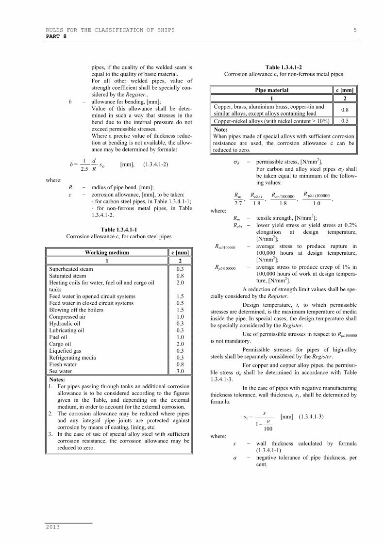
where:R − radius of pipe bend, [mm];c − corrosion allowance, [mm], to be taken:
- for carbon steel pipes, in Table 1.3.4.1-1;- for non-ferrous metal pipes, in Table1.3.4.1-2.
Table 1.3.4.1-1Corrosion allowance c, for carbon steel pipes
Working medium c [mm]1 2
Superheated steam 0.3Saturated steam 0.8Heating coils for water, fuel oil and cargo oiltanks
2.0
Feed water in opened circuit systems 1.5Feed water in closed circuit systems 0.5Blowing off the boilers 1.5Compressed air 1.0Hydraulic oil 0.3Lubricating oil 0.3Fuel oil 1.0Cargo oil 2.0Liquefied gas 0.3Refrigerating media 0.3Fresh water 0.8Sea water 3.0Notes:1. For pipes passing through tanks an additional corrosion
allowance is to be considered according to the figuresgiven in the Table, and depending on the externalmedium, in order to account for the external corrosion.
2. The corrosion allowance may be reduced where pipesand any integral pipe joints are protected againstcorrosion by means of coating, lining, etc.
3. In the case of use of special alloy steel with sufficientcorrosion resistance, the corrosion allowance may bereduced to zero.
Table 1.3.4.1-2Corrosion allowance c, for non-ferrous metal pipes
Pipe material c [mm]1 2
Copper, brass, aluminium brass, copper-tin andsimilar alloys, except alloys containing lead 0.8
Copper-nickel alloys (with nickel content ≥ 10%) 0.5Note:When pipes made of special alloys with sufficient corrosionresistance are used, the corrosion allowance c can bereduced to zero.
σd − permissible stress, [N/mm2].For carbon and alloy steel pipes σd shallbe taken equal to minimum of the follow-ing values:
,0.1
,8.1
,8.1
,7.2
100000/100000// tpmtem RRRR λλ
where:Rm − tensile strength, [N/mm2];Rel/t − lower yield stress or yield stress at 0.2%
elongation at design temperature,[N/mm2];
Rm/t100000 − average stress to produce rupture in100,000 hours at design temperature,[N/mm2];
Rpl/t100000 − average stress to produce creep of 1% in100,000 hours of work at design tempera-ture, [N/mm2].
A reduction of strength limit values shall be spe-cially considered by the Register.
Design temperature, t, to which permissiblestresses are determined, is the maximum temperature of mediainside the pipe. In special cases, the design temperature shallbe specially considered by the Register.
Use of permissible stresses in respect to Rpl/100000is not mandatory.
Permissible stresses for pipes of high-alloysteels shall be separately considered by the Register.
For copper and copper alloy pipes, the permissi-ble stress σd shall be determined in accordance with Table1.3.4.1-3.
In the case of pipes with negative manufacturingthickness tolerance, wall thickness, s1, shall be determined byformula:
s1 =
1001 a
s
−[mm] (1.3.4.1-3)
where:s − wall thickness calculated by formula
(1.3.4.1-1)a − negative tolerance of pipe thickness, per
cent.

6 RULES FOR THE CLASSIFICATION OF SHIPSPART 8
2013
Table 1.3.4.1-3Permissible stress limits for copper and copper alloys pipes, σd [N/mm2]
Pipe materialHeat
treatmentMin.
tensilestrength
Medium design temperature, [oC]
[N/mm2] 50 75 100 125 150 175 200 225 250 275 300Copper annealed 215 41 41 40 40 34 27,5 18,5 − − − −Aluminium brass “ 325 78 78 78 78 78 51 24,5 − − − −Copper-nickel alloy “ 275 68 68 67 65,5 64 62 59 56 52 48 4495/5 and 95/10 −Copper-nickel alloy 70/30 “ 365 81 79 77 73 73 71 69 67 65,5 64 62Notes:1. Intermediate values shall be determined by linear interpolation.2. For materials which are not included in the Table permissible stresses shall be separately considered by the Register.
Table 1.3.4.1-4Definition of the design pressure for fuel oil systems
Workingpressure
Workingtemperature T ≤ 60oC T > 60oC
P ≤ 0,7 MPa 0,3 MPa or max.working pres-sure, whicheveris the greater
0,3 MPa or max.working pres-sure, whicheveris the greater
P > 0,7 MPa max. workingpressure
1,4 MPa or max.working pres-sure, whicheveris the greater
1.3.4.2 Steam pipes with an outside diameter of 80 mmand over conveying superheated steam at a temperature of350oC and over shall be calculated for stresses caused bythermal expansions, and their flanged joints, for strength andtightness.
Calculation of stresses in steam piping causedby thermal expansion should comply with the requirements of13.3.
1.3.4.3 The wall thickness of steel, copper and copperalloy pipes shall not, in any case, be taken less than indicatedin Table 1.3.4.3.
Table 1.3.4.3Minimum permissible wall thickness of pipes, (mm)
P I P E SSteel
Nominalsize
Outsidediameter A B C D E F Austenitic
stainless steelCopper Copper
alloys1 2 3 4 5 6 7 8 9 10 11
8,0 1,0 − − − − − − − −8,0 1,2 − − − − − − 1.0 0.810,2 1,6 − − − − − 1,0 1.0 0.8612,0 1,6 − − − − − 1,0 1.2 1.013,5 1,8 − − − − − 1,0 1.2 1.0816,0 1,8 − − − − − 1,0 1.2 1.017,2 1,8 − − − − − 1,0 1.2 1.019,3 1,8 − − − − − 1,0 1.2 1.01020,0 2,0 − − − − − 1,0 1.2 1.021,3 2,0 − 3,2 − 3,2 2,6 1,6 1,2 1,01525,0 2,0 − 3,2 − 3,2 2,6 1,6 1.5 1.226,9 2,0 − 3,2 − 3,2 2,6 1,6 1.5 1.22030,0 2,0 − 3,2 − 4,0 3,2 1,6 1.5 1.233,7 2,0 − 3,2 − 4,0 3,2 1,6 1.5 1.22538,0 2,0 4,5 3,6 6,3 4,0 3,2 1,6 1.5 1.242,4 2,0 4,5 3,6 6,3 4,0 3,2 1,6 1.5 1.23244,5 2,0 4,5 3,6 6,3 4,0 3,2 1,6 1.5 1.2

RULES FOR THE CLASSIFICATION OF SHIPS 7PART 8
2013
Table 1.3.4.3 - continuesMinimum permissible wall thickness of pipes, (mm)
P I P E SSteel
Nominalsize
Outsidediameter A B C D E F Austenitic
stainless steelCopper Copper
alloys1 2 3 4 5 6 7 8 9 10 11
48,3 2,3 4,5 3,6 6,3 4,0 3,2 1,6 2.0 1.551,0 2,3 4,5 4,0 6,3 4,5 3,6 1,6 2.0 1.554,0 2,3 4,5 4,0 6,3 4,5 3,6 1,6 2.0 1.5
40
57,0 2,3 4,5 4,0 6,3 4,5 3,6 1,6 2.0 1.560,3 2,3 4,5 4,0 6,3 4,5 3,6 2,0 2.0 1.563,5 2,3 4,5 4,0 6,3 5,0 3,6 2,0 2.0 1.55070,0 2,6 4,5 4,0 6,3 5,0 3,6 2,0 2.0 1.576,1 2,6 4,5 4,5 6,3 5,0 3,6 2,0 2.0 1.56582,5 2,6 4,5 4,5 6,3 5,6 4,0 2,0 2.0 1.5
80 88,9 2,9 4,5 4,5 7,1 5,6 4,0 2,0 2.5 2.0101,6 2,9 4,5 4,5 7,1 6,3 4,0 2,0 2.5 2.090108,0 2,9 4,5 4,5 7,1 7,1 4,5 2,0 2.5 2.0114,3 3,2 4,5 4,5 8,0 7,1 4,5 2,3 2.5 2.0127,0 3,2 4,5 4,5 8,0 8,0 4,5 2,3 2.5 2.0100133,0 3,6 4,5 4,5 8,0 8,0 5,0 2,3 3.0 2.5139,7 3,6 4,5 4,5 8,0 8,0 5,0 2,3 3.0 2.5152,4 4,0 4,5 4,5 8,8 8,8 5,6 2,3 3.0 2.5125159,0 4,0 4,5 4,5 8,8 8,8 5,6 2,3 3.0 2.5168,3 4,0 4,5 4,5 8,8 8,8 5,6 2,3 3.0 2.5150177,8 4,5 5,0 5,0 8,8 − − 2,3 3.0 2.5
175 193,7 4,5 5,4 5,4 8,8 − − 2,3 3.5 3.0200 219,1 4,5 5,9 5,9 8,8 − − 2,6 3.5 3.0
244,6 5,0 6,3 6,3 8,8 − − 2,6 3.5 3.0225267,0 5,0 6,3 6,6 8,8 − − 2,6 3.5 3.0273,0 5,0 6,3 6,3 8,8 − − 2,9 4.0 3.5250298,5 5,6 6,3 6,3 8,8 − − 2,9 4.0 3.5
300 323,9 5,6 6,3 6,3 8,8 − − 3,6 4.0 3.5355,6 5,6 6,3 6,3 8,8 − − 3,6 4.0 3.5350368,0 5,6 6,3 6,3 8,8 − − 3,6 4.0 3.5406,4 6,3 6,3 6,3 8,8 − − 3,6 4.0 3.5400419,0 6,3 6,3 6,3 8,8 − − 4,0 4.0 3.5457,2 6,3 6,3 6,3 8,8 − − 4,0 4.0 3.5450508,0 − − − − − − 4,0 4.5 4.0
Notes of Table 1.3.4.3 :
Columns A, B, C and D in the table apply to the following services:A Pipes in general.B Vent, overflow and sounding pipes for integral tanks.C Bilge, ballast and sea water pipes.D Bilge, ballast, vent, overflow and sounding pipes passing through fuel tanks; Bilge, vent, overflow, sounding and fuel pipes passing through ballast tanks.E Piping of CO2 fire extinguishing system - from cylinders to discharge valves.F Piping of CO2 fire extinguishing system - From discharge valves to discharge nozzles.
8 RULES FOR THE CLASSIFICATION OF SHIPSPART 8
2013
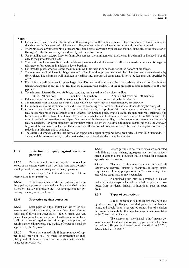
Notes:1. The nominal sizes, pipe diameters and wall thickness given in the table are many of the common sizes based on interna-
tional standards. Diameter and thickness according to other national or international standards may be accepted.2 Where pipes and any integral pipe joints are protected against corrosion by means of coating, lining etc. at the discretion of
the Register, the thickness may be reduced by not more than 1 mm.3. For sounding pipes, except those for flammable cargoes, the minimum wall thicknesses in column B is intended to apply
only to the part outside the tank.4. The minimum thicknesses listed in this table are the nominal wall thickness. No allowance needs to be made for negative
tolerance or for reduction in thickness due to bending.5. For threaded pipes, where allowed, the minimum wall thickness is to be measured at the bottom of the thread.6. The minimum wall thickness for bilge lines and ballast lines through deep tanks will be subject to special consideration by
the Register. The minimum wall thickness for ballast lines through oil cargo tanks is not to be less than that specified by4.2.2.
7. The minimum wall thickness for pipes larger than 450 mm nominal size is to be in accordance with a national or interna-tional standard and in any case not less than the minimum wall thickness of the appropriate column indicated for 450 mmpipe size.
8. The minimum internal diameter for bilge, sounding, venting and overflow pipes shall be: Bilge 50 mm bore Sounding 32 mm bore Venting and overflow 50 mm bore9. Exhaust gas pipe minimum wall thickness will be subject to special consideration by the Register.10. The minimum wall thickness for cargo oil lines will be subject to special consideration by the Register.11. For austenitic stainless steel diameters and thickness according to national or international standards may be accepted.12. Columns E and F – Pipes are to be galvanized at least inside, except those fitted in the engine room where galvanizing
may not be required at the discretion of the Register. For threaded pipes, where allowed, the minimum wall thickness is tobe measured at the bottom of the thread. The external diameters and thickness have been selected from ISO Standards forsmooth welded and seamless steel pipes. Diameter and thickness according to other national or international standardsmay be accepted. For larger diameters the minimum wall thickness will be subject to special consideration by the Register.In general the minimum thickness is the nominal wall thickness and no allowance need be made for negative tolerance orreduction in thickness due to bending.
13. The external diameters and the thicknesses for copper and copper alloy pipes have been selected from ISO Standards. Di-ameter and thickness according to other national or international standards may be accepted.
1.3.5 Protection of piping against excessivepressure
1.3.5.1 Pipes in which pressure may be developed inexcess of the design pressure shall be fitted with arrangementswhich prevent the pressure rising above design pressure.
Open escape of fuel oil and lubricating oil fromsafety valves is not permitted.
1.3.5.2 Where provision is made for a reducing valve onthe pipeline, a pressure gauge and a safety valve shall be in-stalled on the lower pressure side. An arrangement for by-passing reducing valve is allowed.
1.3.6 Protection against corrosion
1.3.6.1 Steel pipes of bilge, ballast and sea water sys-tems as well as of air, sounding and overflow pipes of watertanks and of alternating water ballast - fuel oil tanks, gas ventpipes of cargo tanks and air pipes of cofferdams in tankers,shall be protected against corrosion upon completion ofbending and welding works. The method of protection shall beapproved by the Register.
1.3.6.2 Where bottom and side fittings are made of cop-per alloys, provision shall be made for protection of shellplating and all elements which are in contact with such fit-tings, against corrosion.
1.3.6.3 Where galvanised sea water pipes are connectedwith fittings, pump casings, aggregates and heat exchangersmade of copper alloys, provision shall be made for protectionagainst contact corrosion.
1.3.6.4 The use of aluminium coatings on board oiltankers and chemical tankers is prohibited in cargo tanks,cargo tank deck area, pump rooms, cofferdams or any otherarea where cargo vapour may accumulate
Aluminised pipes may be permitted in ballasttanks, in inerted cargo tanks and, provided the pipes are pro-tected from accidental impact, in hazardous areas on opendeck.
1.3.7 Types of connections
Direct connections os pipe lengths may be madeby direct welding, flanges, threaded joints or mechanicaljoints, and should be to a recognised standard or of a designproven to be suitable for the intended purpose and acceptableto the Classification Society.
The expression “mechanical joints” means de-vices intended for direct connection of pipe lengths other thanby welding, flanges or threaded joints described in 1.3.7.1,1.3.7.2 and 1.3.7.3 below.
RULES FOR THE CLASSIFICATION OF SHIPS 9PART 8
2013
1.3.7.1 Welded connectionsWelding and non destructive testing of welds are
to be carried out in accordance and requirements of Classifi-cation Society.
.1 But welded jointsButt welded joints shall be of full penetra-tion type generally with or without specialprovision for a high quality of root side.Butt welded joints with special provisionfor a high quality of root side may be usedfor piping of any Class, any outside di-ameter.Butt welded joints without special provi-sion for a high quality of root side may beused for piping systems of Class II and IIIirrespective of outside diameter.
.2 Slip-on sleeve and socket welded jointsSlip-on sleeve and socket welded jointsare to have sleeves, sockets and weldmentsof adequate dimensions conforming toClassification Society Rules or recognizedStandard.Slip-on sleeve socket welded joints maybe used in Class III systems, any outsidediameter.In particular cases, slip-on sleeve andsocket welded joints may be allowed bythe Classification Society for piping sys-tems Class I and II having outside diame-ter ≤ 88.9 mm except for piping systemsconveying toxic media or services wherefatigue, severe erosion or crevice corro-sion is expected to occur.
1.3.7.2 Flange connections.1 The dimensions and configuration of
flanges and bolts are to be chosen in ac-cordance with recognized standards.Gaskets are to be suitable for the mediabeing conveyed under design pressure andtemperature conditions and their dimen-sions and configuration are to be in accor-dance with recognised standards.For non-standard flanges the dimensionsof flanges and bolts are to be subject tospecial consideration.
.2 Examples of flange attachements areshown in 1.3.7.2. However, other types offlange attachments may be considered bythe Classification Society in each par-ticualr case.
.3 Flange attachments are to be in accordancewith national or international standardsthat are applicable to the piping system
and are to recognized the boundary fluids,design pressure and temperature condi-tions, external or cyclic loading and loca-tion, as shown in table 1.3.7.7.
1.3.7.3 Slip-on threaded jointsSlip-on threaded joints having pipe threads
where pressure-tight joints are made on the threads with par-allel or tapered threads, shall comply with requirements of arecognized national or international standard.
Sliped-on threaded joints may be used for out-side diameters as stated below except for piping systems con-veying toxic or flammable media or services where fatigue,severe erosion or crevice corrosion is expected to occur.
Threaded joints in CO2 system shall be allowedonly inside protected spaces and in CO2 cylinder rooms.
Threaded joints for direct connectors of pipelengths with tapered thread are to be allowed for:
a) Class I, outside diameter not more than33.7 mm,
b) Class II and Class III, outside diameternot more than 60.3 mm.
Threaded joints with parallel thread are to beallowed for Class III, diameter not more than 60.3 mm.
In particular cases, sizes in excess of those men-tioned above may be accepted by the Classification Society ifin compliance with a recognized national and/or internationalstandard.
1.3.7.4 Mechanical jointsDue to the great variations in design and con-
figuration of mechanical joints, no specific recommendationregarding calculation method for theoretical strength calcula-tions is given in these requirements. The Type Approval is tobe based on the results of testing of the actual joints.
These requirements are applicable to pipe un-ions, compression couplins, slip-on joints as shown in Fig.1.3.7.4. Similar joints compling with these requirements maybe acceptable.
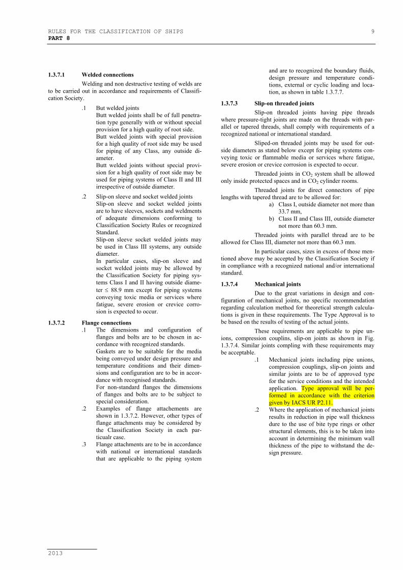
.1 Mechanical joints including pipe unions,compression couplings, slip-on joints andsimilar joints are to be of approved typefor the service conditions and the intendedapplication. Type approval will be per-formed in accordance with the criteriongiven by IACS UR P2.11.
.2 Where the application of mechanical jointsresults in reduction in pipe wall thicknessdure to the use of bite type rings or otherstructural elements, this is to be taken intoaccount in determining the minimum wallthickness of the pipe to withstand the de-sign pressure.

10 RULES FOR THE CLASSIFICATION OF SHIPSPART 8
2013
Fig. 1.3.7.2Examples of flange attachements
NOTE: For type D, the pipe and flange are to be screwed with a tapered thread and the diameter of the screw portion of the pipeover the thread is not to be appreciably less tahn the outside diameter of the unthreaded pipe. For certain types of thread,after the flange has been screw hard home, the pipe is to be expanded into the flange.

RULES FOR THE CLASSIFICATION OF SHIPS 11PART 8
2013
.3 Construction of mechanical joints is toprevent the possibility of tightness failureaffected by pressure pulsation, piping vi-bration, temperature variation and othersimilar adverse effects occuring duringoperation on board.
.4 Material of mechanical joints is to becompatible with the piping material andinternal and external media.
.5 Mechanical joints are to be tested whereapplicable, to a burst pressure of 4 timesthe design pressure.For design pressures above 200 bar the re-quired burst pressure will be speciallyconsidered by the Classification Society.
.6 In general, mechanical joints are to be offire resistant type as required by Table1.3.7.5.
.7 Mechanical joints, which in the event ofdamage could cause fire or flooding, arenot be used in piping sections directlyconnected to the sea openings or tankscontaining flammable fluids.
.8 The mechanical joints are to be designedto withstand internal and external pressureas applicable and where used in suctionlines are to be capable of operating undervacuum.
.9 The number of mechnical joints in oilsystems is to be kept to a minimum. Ingeneral, flanged joints conforming to rec-ognised standards are to be used.
.10 Piping in which a mechanical joint is fittedis to be adequately adjusted, aligned andsupported. Supports or hangers are not tobe used to force alignment of piping at thepoint of connection.
.11 Slip-on joints are not to be used in pipe-lines in cargo holds, tanks, and otherspaces which are not easily accessible,unless approved by the Classification So-ciety.Application of these joints inside tanksmay be permitted only for the same mediathat is in the tanks.Unrestrained Slip-on joints are to be usedonly in cases where compensation of lat-eral pipe deformation is necessary. Usageof these joints as the main means of pipeconnection is not permitted.
.12 Application of mechanical joints and theiracceptable use for each service is indicatedin Table 1.3.7.5, dependence upon theClass of piping, pipe dimensions, workingpressure and temperature is indicated inTable 1.3.7.6In particular cases, size in excess of thosementioned above may be accepted by theClassification Society if in compliancewith a recognized national and/or interna-tional standard.
Pipe UnionsWeldedandBrazedTypes
Compression CouplingsSwageType
Fig. 1.3.7.4Examples of mechanical joints

12 RULES FOR THE CLASSIFICATION OF SHIPSPART 8
2013
PressType
Bite Type
FlaredType
Slip-on JointsGripType
MachineGroovedtype
Fig. 1.3.7.4Examples of mechanical joints

RULES FOR THE CLASSIFICATION OF SHIPS 13PART 8
2013
SlipType
Fig. 1.3.7.4Examples of mechanical joints
1.3.7.5 Application of mechanical jointsThe following table indicates systems where the
various kinds of joints may be accepted. However, in allcases, acceptance of the joints type is to be subject to approvalfor the intended application, and subject to conditions of theapproval and applicable Rules.

14 RULES FOR THE CLASSIFICATION OF SHIPSPART 8
2013
Table 1.3.7.5
Kind of connectionsSystems Pipe Unions Compression Couplings 6) Slip-on JointsFlammable fluids (Flash point ≤ 60o)
1 Cargo oil lines + + +5)2 Crude oil washing lines + + +5)3 Vent lines + + +3)
Inert gas4 Water seal effluent lines + + +5 Scrubber effluent lines + + +6 Main lines + + +2)5)7 Distribution lines + + +5)
Flammable fluids (Flash point > 60o)8 Cargo oil lines + + +5)9 Fuel oil lines + + +3)2)10 Lubricating oil lines + + +2)3)11 Hydraulic oil + + +2)3)12 thermal oil + + +2)3)
Sea water13 Bilge lines + + +1)14 Fire main and water spray + + +3)15 Foam system + + +3)16 Sprinkler system + + +3)17 Ballast system + + +1)18 Cooling water system + + +1)19 Tank cleaning services + + +20 Non-essential systems + + +
Fresh water21 Cooling water system + + +1)22 Condensate return + + +1)23 Non-essential system + + +
Sanitary/Drains/Scruppers24 Deck drains (internal) + + +4)25 Sanitary drains + + +
26 Scuppers and discharge(overboard) + + -
Sounding/Vent27 Water tanks/Dry spaces + + +28 Oil tanks (f.p. > 60oC) + + +2)3)
Miscellaneous29 Starting/Control air 1) + + -
30 Service air(non-essential) + + +
31 Brine + + +32 CO2 system 1) + + -33 Steam + + +7)
Abbreviations+ Application is allowed- Application is not allowedNOTE:1) Inside machinery spaces of category A – only approved fire resistant types2) Not inside machinery spaces of category A or accommodation spaces. May be accepted in other machineryspaces provided the
joints are located in easly visible and accessible positions.3) Approved fire resistant types4) Above free board deck only5) In pump rooms and open decks – only approved fire resistant types6) If Compression Coupling include any components which readily deteriorate in case of fire, they are to be of approved fire resis-
tant type as required for Slip-on-joints.7) Slip type joints as shown in Fig. 1.3.7.4, provided that they are restrained on the pipes, may be used for pipes, on deck with a de-
sign pressure of 10 bar or less
RULES FOR THE CLASSIFICATION OF SHIPS 15PART 8
2013
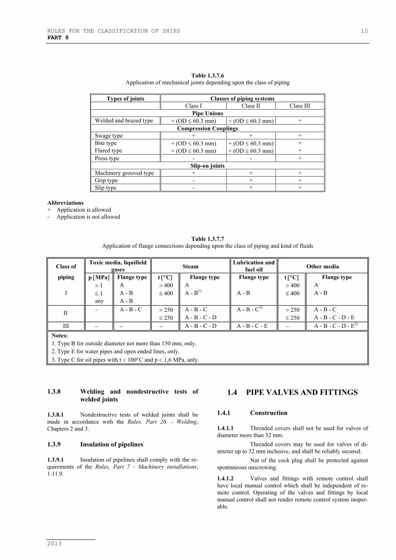
Table 1.3.7.6Application of mechanical joints depending upon the class of piping
Types of joints Classes of piping systemsClass I Class II Class III
Pipe UnionsWelded and brazed type + (OD ≤ 60.3 mm) + (OD ≤ 60.3 mm) +
Compression CouplingsSwage type + + +Bite type + (OD ≤ 60.3 mm) + (OD ≤ 60.3 mm) +Flared type + (OD ≤ 60.3 mm) + (OD ≤ 60.3 mm) +Press type - - +
Slip-on jointsMachinery grooved type + + +Grip type - + +Slip type - + +
Abbreviations+ Application is allowed- Application is not allowed
Table 1.3.7.7Application of flange connections depending upon the class of piping and kind of fluids
Class ofToxic media, liquifield
gases SteamLubrication and
fuel oil Other media
piping p [MPa] Flange type t [°C] Flange type Flange type t [°C] Flange type> 1 A > 400 A > 400 A
I ≤ 1 A - B ≤ 400 A - B1) A - B ≤ 400 A - Bany A - B− A - B - C > 250 A - B - C A - B - C3) > 250 A - B - C
≤ 250 A - B - C - D ≤ 250 A - B - C - D - EIII − − − A - B - C - D A - B - C - E − A - B - C - D - E2)
Notes:1. Type B for outside diameter not more than 150 mm, only.2. Type E for water pipes and open ended lines, only.3. Type C for oil pipes with t < 100°C and p < 1,6 MPa, anly.
1.3.8 Welding and nondestructive tests ofwelded joints
1.3.8.1 Nondestructive tests of welded joints shall bemade in accordance with the Rules, Part 26. - Welding,Chapters 2 and 3.
1.3.9 Insulation of pipelines
1.3.9.1 Insulation of pipelines shall comply with the re-quirements of the Rules, Part 7 - Machinery installations,1.11.9.
1.4 PIPE VALVES AND FITTINGS
1.4.1 Construction
1.4.1.1 Threaded covers shall not be used for valves ofdiameter more than 32 mm.
Threaded covers may be used for valves of di-ameter up to 32 mm inclusive, and shall be reliably secured.
Nut of the cock plug shall be protected againstspontaneous unscrewing.
1.4.1.2 Valves and fittings with remote control shallhave local manual control which shall be independent of re-mote control. Operating of the valves and fittings by localmanual control shall not render remote control system inoper-able.
II

16 RULES FOR THE CLASSIFICATION OF SHIPSPART 8
2013
If the valves are provided with remote controlsystem they shall be so constructed that, in case of failure ofthe remote control system the valves remain, or automaticallyreturn, in a position that will not bring the ship into dangeroussituation.
1.4.1.3 Compressed air shall not be used as energysource in remote control systems for the valves and fittings in-stalled in cargo tanks.
1.4.1.4 Valves and fittings in piping systems are to becompatible with the pipes to which they are attached in re-spect of their strength (see 1.3.4.1-1 for design pressure) andare to be suitable for effective operation at the maximumworking pressure they will experience in service.
1.4.2 Marking of valves and fittings
1.4.2.1 Shut-off valves and fittings shall be providedwith conspicuous name plates bearing legible inscriptionsspecifying their purpose.
1.4.2.2 Remote control system shall have, in the controlstations, a fixed nameplates specifying their purpose and indi-cators showing their open or closed positions.
Where the remote control is intended only forclosing the valves and fittings, such indicators may be omit-ted.
1.4.3 Arrangement and installation of valvesand fittings
1.4.3.1 Valves and fittings on watertight bulkheads shallbe secured by studs screwes into reinforced steel flangewelded to the bulkhead. It is permitted to instal short pipeswelded to the flanges between valves and bulkheads.
The thread stud holes shall not be deeper thanthe thickness of welded flange.
1.4.3.2 Valve chests and manual-controlled valves shallbe placed in easy accessible places.
Fuel oil system valve drives, if valves are lo-cated in the engine room, shall be fitted on easy accessibleplaces, above floor platings.
1.4.3.3 Instruments for control and measurement in fueloil and lubricating oil systems shall be provided with valves orcocks as to be separated from pipeline. Sensitive parts ofthermometers shall be protected by solid sleeves.
1.5 SEA WATER INLET BOXES, ICEBOXES,OPENINGS IN SHELL PLATING
AND BOTTOM AND SIDE FITTINGS
1.5.1 Sea water inlet boxes and ice boxes
1.5.1.1 Sea water inlet valves shall be placed, in gen-eral, on the inlet box or ice box and shall be approved by theRegister.
1.5.1.2 In ships with ice strengthening at least one of thesea inlet water boxes shall comply with the following re-quirements:
.1 Sea inlet water boxes shall be fitted in vi-cinity of the ship's centerline and if possi-ble shall be located after.
.2 In determining the size of a box, l m3 maybe taken at every 750 kW of total power ofpropelling and auxiliary engines, installedon board ship.
.3 Height of inlet boxes for navigation in iceshall provide proper removal of ice and airduring operation of discharge system.
.4 Cooling water recirculation system shallbe fitted on the inlet box. Cross-sectionalarea of the system shall not be less thanthat of the discharge water collector.
.5 If requirements .2 and .3 can not be satis-fied, the application of two mutually re-placeable recirculation inlet and drawingboxes shall be allowed, according to .4.
1.5.1.3 The inside of the boxes shall be accessiblethrough the removable grates or manholes. If a manhole isfitted in the ice box for this purpose, it shall be located abovethe deepest load line.
1.5.2 Openings in shell plating and bottom andside fittings
1.5.2.1 Number of openings in the shell plating shall bekept to a minimum. Therefore, where possible, dischargepipelines shall be connected to common discharges.
1.5.2.2 Arrangement of sea inlet and discharge openingsin the ship's shell plating shall be such as to prevent:
.1 sewage, ash and other wastes being suckedby sea water pumps;
.2 sewage and water discharged shall not beallowed to pass into the ship's spacesthrough the side scuttles and into the life-boats and liferafts when launching.
Where it is impracticable to comply with re-quirement .2, discharge openings shall be fitted with appropri-ate arrangements which prevent discharged water from pene-trating into the ship's spaces, lifeboats and liferafts.
1.5.2.3 Openings in the shell plating of sea water inletboxes and ice boxes shall be fitted with protecting gratings.
Instead of gratings it is allowed to make theholes or slots in the ship's plating.
Net area of openings or grating shall not be lessthan 2,5 times the area of fitting of the discharge water andwhere the ship has an ice strengthening then it shall be at least4 times greater than the area of the specified fitting.
Hole diameters and slot widths on gratings orshell platings shall be approximately 20 [mm].
Gratings of inlet boxes shall be provided, for thepurpose of cleaning, with the steam or compressed air ar-rangement.

RULES FOR THE CLASSIFICATION OF SHIPS 17PART 8
2013
Cleaning pipeline shall be provided with non-return shut-off valves. The steam or compressed air pressurein cleaning system shall not exceed 0,5 MPa.
1.5.2.4 Overboard discharges (except those specified in1.5.2.12), leading from the spaces below the freeboard deck orfrom closed superstructures or deckhouses on the freeboarddeck (see Rules, Part 3 - Hull Equipment, 7.5.1.2), which haveor may have open ends in these spaces, as a rule, shall be pro-vided with a non return valve capable of being remotelyclosed from a readily accessible place situated above thebulkhead deck for ships which are to comply with the re-quirements for subdivision in damaged condition, and abovethe freeboard deck for all other ships.
Instead of one non-return valve with positivemeans of closing, provisions may be made for a non-returnvalve and a shut-off valve capable of being remotely operatedfrom the bulkhead deck or freeboard deck.
The valve remote controls shall be providedwith an indicator: “Closed” or “Open”.
1.5.2.5 In ships which need not comply with the re-quirements for subdivision in damaged condition, the sanitarydrainage and overflow non-return valves led overboard maybe operated locally, if such valves are placed on shell platingin the manned engine room.
1.5.2.6 Where the vertical distance from the summerload line (from the summer timber waterline in ships withtimber freeboard) to the inboard end of the discharge pipe ex-ceeds 0,01 of the ship's length the discharge pipe may be fittedwith two non-return valves without positive means of closing,provided that one valve is installed at the shell and the secondabove the deepest loadline in sea water assigned to that ship,in a position readily accessible under all service conditions.Where a shut-off valve is installed between these non-returnvalves, the second non return valve need not be fitted abovethe deepest load line in sea water allowed for that ship.
1.5.2.7 Where, in ships which need not comply with therequirements for subdivision in damaged condition, the verti-cal distance from the summer load line (from the summer tim-ber line for ships with timber freeboard) to the inboard end ofthe discharge pipe exceeds 0,02 of the ship's length the dis-charge opening may have only one non-return valve, withoutpositive means of closing.
1.5.2.8 In ships which are to comply with the require-ments for subdivision in damaged condition, one non-returnvalve is permitted at the shell, if the distance from the inboardend of the discharge pipe to the damaged waterline exceeds0,3 [m], as calculated for the worst conditions of flooding.
1.5.2.9 The specified requirements for non-return valvesdo not apply to overboard discharge openings which shall beclosed while at sea (e.g. openings in top side ballast tanks fordrainage by gravity).
1.5.2.10 In ships of restricted navigation area 6,7 or 8overboard discharges from spaces situated on freeboard deckand below it may be provided with only one non-return shut-off valve with local control.
1.5.2.11 Scuppers and drain pipes led overboard fromopen decks and spaces, except pipes specified in 1.5.2.4, if areleading to outer shell plating lower than 450 [mm] below
freeboard deck, or for less than 600 [mm] above summer loadwaterline, shall be fitted with non-return valves at the shellplating.
Wall thickness of scuppers and drain pipes shallnot be less than those indicated in Table 1.3.4.3, column 4.
Non-return valves may be omitted if pipe thick-ness below freeboard deck and closed superstructures is notless than:
7 [mm] for d ≤ 80 [mm]10 [mm] for d = 180 [mm]12,5 [mm] for d ≥ 220 [mm]
where:d − pipe outside diameter.
Intermediate values are determined by linearinterpolation.
Scuppers from the superstructures and deck-houses shall be led on ship's side.
Scuppers from spaces intended for carriage ofmotor vehicles with fuel in their tanks are to prevent accu-mulation of water in this space when using water spraying fireextinguishing system. Drainage arrangement shall complywith the requireements in MSC.1/Circ.1320 – (Guidelines forthe drainage of fire-fighting water from closed vehicle and ro-ro spaces and special category spaces of passenger and cargoships).
1.5.2.12 Sea water inlet and discharge valves, situated onshell plating in machinery spaces, serving main and auxiliarymachinery shall be provided with control from inside of thesespaces. The controls shall be easily accessible and fitted withan indicator showing whether the valves are "Closed" or"Open".
As a rule, the discharge valves at the shall plat-ing shall be of non-return shut-off type.
Where this is impracticable, use of other type ofvalves and valves arrangement on the shell plating will bespecially considered by the Society.
In any event, the butterfly valves withoutflanges are not to be used for water inlets or overboard dis-charges unless provisions are made to allow disassembling atsea of the pipes served by these valves without any risk offlooding.
1.5.2.13 Means for operating bottom inlet fittings shallbe situated in readily accessible places and shall be fitted withan arrangement indicating whether the valve is open or closed.
In passenger ships, these means shall be locatedabove the floor plating of machinery spaces.
In cargo ships, these means are recommended tobe located above the floor plating of machinery spaces.
1.5.2.14 In unattended machinery spaces, the location ofthe controls of any valve serving a sea inlet, a discharge belowthe waterline or a bilge injection system shall be so sited as toallow adequate time for operation in case of influx of water tothe space, having regard to the time likely to be required inorder to reach and operate such controls.
A calculation shall be carried out to show that the timetaken from alarm activation plus the time to reach and fullyclose manually operated or powered valves is less than thetime taken for the influx of water to reach the control without

18 RULES FOR THE CLASSIFICATION OF SHIPSPART 8
2013
submergence of the platform on which the person is operatingthe valve.
If the level to which the space could become floodedwith the ship in the fully loaded condition so requires, ar-rangements shall be made to operate the controls from a posi-tion above such level.
The requirements of this regulation are not applica-ble to valves serving an emergency bilge system provided thatthe emergency bilge suction piping is:
• fitted with a normally closed non-return valve withpositive means of closing;
• located inboard of a shell valve that is fitted with thecontrol arrangements required by this regulation.
Since the various Flag Administrations issued theirown interpretations, unless expressly provided otherwise theapplication of this regulation shall be as follow:
.1 For ships registered under Croatian Flag:• If the subdivision and damage stabil-
ity requirements do not apply to theship, the controls has to be accessiblefrom a position above the freeboarddeck.
• If the subdivision and damage stabil-ity requirements apply to the ship, thecontrols has to be accessible from aposition above the level to which thespace could become flooded within 30minutes, with the ship in the fullyloaded conditions. The highest level isto be determined by the calculationsfor each valve individually.
.2 For ships under the Flag other than Croa-tian:• Criterion required by National
Authority of the country in which theship will be registered shall be com-plied with.
• If the National Authority has no par-ticular interpretation and additional re-quirements, the level to which thespace could become flooded shall bedocumented by relevant calculation foreach particular valve, taking 10 min-utes as regarded time for operation.
• Where documented by the calculationthat the water level is not above thetank top floor after 10 minutes fromthe initiation of the uppermost bilgelevel alarm, the valve operation fromthe tanktop floor could be accepted.
1.5.2.15 As a rule, bottom and side fittings shall be at-tached to welded pads and shall be approved by the Register.
The fittings are allowed to be installed on pipeswelded to the shell plating, provided that the latter are of rigidconstruction and of minimum length and shall be approved bythe Register.
Thickness of the pipes shall not be less than thethickness indicated in 1.5.2.11.
The stud holes shall not penetrate the shell plat-ing but shall be only within the welded pads.
It is not allowed to use gaskets made of lead orof materials, which are subject to destruction in the event offire.
1.5.2.16 In ships with ice strengthening, the fittingsabove the load waterline shall have the heating facilities.
1.5.2.17 No part of fittings installed on shell plate belowthe bulkhead deck, as well as of the bottom fittings, shall bemade of materials which can readily be deteriorated in theevent of fire.
1.5.2.18 Spindles and closing parts of the bottom andshell plate fittings shall be manufactured of materials resistantto the corroding action of sea water.
1.5.2.19 For scuppers, inlets and discharges requirementssee also 16.
1.6 LEADING OF PIPELINES
1.6.1 Leading of pipelines through watertightand fire-resisting structures
1.6.1.1 The number of pipe penetrations in watertightsubdivisions is to be kept to a minimum compatible with thedesign and proper operation of the ship. Where penetrationsare necessary, arrangements are to be made to maintain thewatertight integrity.
Unless otherwise specified, the pipelines passingthrough the main watertight bulkheads, as a rule, shall be situ-ated at a distance from the ship's side of at least 1/5 of theship's breadth (see 2.3.6). See also 1.6.7.
Depending of the type of ship, this criterionshall be a subject to subdivision and damage stability re-quirements in relevant Chapter of the Rules Pt 5 - Subdivi-sion.
Where this requirement is impracticable, meas-ures shall be taken to prevent the spread of sea water beyondthe damaged compartment into other watertight compartmentsand tanks, in the event of damage to the ship's hull and dete-rioration of the pipes.
1.6.1.2 Passage through the collision bulkhead.1 The collision bulkhead may be pierced
below the bulkhead deck by not more thanone pipe for dealing with fluid in the fore-peak tank.
.2 If the forepeak is divided to hold two dif-ferent kinds of liquids, the collision bulk-head may be pierced below the bulkheaddeck by two pipes, provided the Registeris satisfied that there is no practical alter-native to the fitting of such a second pipeand that, having regard to the additionalsubdivision provided in the forepeak, thesafety of the ship is maintained.
The National Authority of the country inwhich the ship will be registered may also haveadditional requirements..3 Each pipe piercing the collision bulkhead
below the bulkhead deck is to be fittedwith a shut-off valve capable of being op-

RULES FOR THE CLASSIFICATION OF SHIPS 19PART 8
2013
erated from above the bulkhead deck, thevalve chest being secured inside the fore-peak to the collision bulkhead.However, the Register could accept thefitting of this valve on the after side of thecollision bulkhead provided that the valveis readily accessible under all service con-ditions and the space in which it is locatedis not a cargo space.The National Authority of the country inwhich the ship will be registered may alsohave additional requirements.
.4 The valves fitted on collision bulkheadbelow the bulkhead deck are to be of steel,bronze or other approved ductile material.Valves of ordinary cast iron or similarmaterial are not acceptable.
.5 The required valve control from above thebulkhead deck is not mandatory for shipsother than passenger ships with restrictedareas of navigation 5 to 8, which need notto comply with the requirements for sub-division in damaged condition, providedthat related pipeline is not passing throughcargo holds and fuel tanks.
1.6.1.3 The pipes used for watertight passages belowthe bulkhead deck shall have substantial thickness, not lessthan specified in Table 1.3.4.3-column D.
Minimal thickness of pipes for watertight pas-sages fitted above the bulkhead deck, depending on pipe di-ameter, shall be at least for 1,5 to 3 [mm] greater than the wallthickness of pipe fitted to the passage.
1.6.1.4 Where the pipelines pass through watertightbulkheads, decks and other watertight structures, suitablebulkhead pieces (bushes) flanges or other similar arrange-ments shall be used to ensure the watertightness of the struc-ture concerned.
Holes for bolts are not to penetrate the water-tight bulkhead but they must end in welded pads. Gaskets oflead or other materials which are not fire resistant are notpermitted.
1.6.1.5 Where pipes pass through watertight bulkheadsand decks that confine watertight compartments, valves capa-ble of being operated from above the bulkhead deck shall befitted. The valves shall be of steel or of another materialequivalent to steel in fire resistance.
This requirement does not apply to pipes of bal-last system led within double bottom..
1.6.1.6 Where it is necessary to carry pipes through fire-resisting bulkheads, the requirements of the Rules, Part 17 -Fire Protection, 2.1.3.13 shall be complied with.
1.6.1.7 Where plastic pipes pass through main fire-resisting bulkheads, steel sockets of adequate length shall beused with valves capable of being closed from either side ofthe bulkhead.
These valves shall be of steel or other materialequivalent to steel in fire resistance.
1.6.1.7 Depending of the subdivision and damage stabil-ity requirements in relevant Chapter of the Rules Pt 5, the bulk-heads and decks forming watertight boundaries may be fittedwith suitable cross-flooding pipelines and particular fittingsfor equalization of the ship in case of unsymmetrical flooding.
Where controls to cross-flooding fittings areprovided, they shall be operable from above the bulkheaddeck. These fittings together with their controls shall be ac-ceptable to the Administration.
1.6.2 Leading of pipes in tanks
1.6.2.1 For routing of pipes, following general require-ments, inter alia, are to be complied with:
.1 In general, the passage of pipes throughtanks, when permitted shall include specialarrangements such as reinforced thicknessor tunnels. It applies particularly for thefuel oil pipes, bilge pipes, ballast pipes, airvent pipes, sounding pipes, overflowpipes, scuppers and sanitary discharges.Junctions of pipes inside tanks are to bemade by welding or flange connections.
.2 Drinking water and feed water pipes shallnot be led without tunnel through fuel andlubricating oil storage tanks.
.3 Fuel oil and lubrication oil pipes shall notpass through drinking water and feed wa-ter tanks unless they are led in oiltighttunnels, forming part of the tank structure.
.4 Sea water and lubricating oil pipes, as wellas air overflow and sounding pipes are al-lowed to be led through fuel oil storagetanks if seamless pipes without detachablejoints inside such tanks are used. Wheredetachable joints cannot be avoided, theyshall be flange connections with gasketsresisant to oil.
1.6.2.2 Where no tunnels are used in leading pipesthrough tanks and where compensation of thermal expansionis required, bends of the pipes themselves shall be made insidethe tank.
Where pipes are led through tunnels, it is rec-ommended that the thermal compensators be situated outsidethe tunnel.
1.6.2.3 Leading of pipes through tanks in oil tankersshall comply with requirements stated in 4.2.
1.6.3 Leading of pipes in cargo holds andother spaces
1.6.3.1 Pipes shall be secured in a way as not to inter-fere with the stresses from thermal expansion, undue defor-mations of ship structure and vibrations.
1.6.3.2 Pipes passing through cargo holds, chain lockersand other spaces in which they are subject to mechanicaldamage shall be adequately protected.

20 RULES FOR THE CLASSIFICATION OF SHIPSPART 8
2013
1.6.3.3 Fuel, steam and water pipings as well as pres-sure pipes of hydraulic drives, with the exception of bilgepipes, are, as a rule, not allowed in dry cargo holds.
In exceptional cases, which are subject to specialconsideration by the Register, these pipes may be allowedprovided they are led in tunnels, or where the pipes employedare of increased thickness and protected by strong steel cas-ings.
1.6.3.4 Steam piping shall not be led through paintrooms, lantern rooms or other spaces intended for carriage ofreadily flamable materials.
1.6.3.5 Where hot pipes pierce bulkheads made of com-bustible materials, provision shall be made for structuralmeasures preventing bulkheads from being affected by in-creased temperature.
1.6.3.6 Fuel oil piping shall not be led through accomo-dation and service spaces. An exception can be made for fueloil pipelines of the emergency diesel-generator, and also forfilling pipes which are alowed to be led through the sanitaryspaces, provided the pipes used have a thickness of not lessthan 5 mm and no detachable joints are employed.
1.6.3.7 Pipes intended for carrying hot media and hav-ing considerable longitudinal extension shall have thermalcompensators or as many bends as will provide adequate self-compensation of the pipeline.
Internal radii of bending shall not be less thanspecified in 1.3.2.
1.6.3.8 Pipings of all systems and ventilation ductsshall, where necessary, be fitted with suitable arrangements topermit drainage or blowing-off the working medium or con-densates.
Structural measures shall be taken to protect thehull and equipment from adverse effect of the agents dis-charged.
1.6.4 Leading of pipes in refrigerated cargospaces
1.6.4.1 No pipes shall be led through refrigerated cargospaces unless they are intended to serve these spaces. Whereleading of such pipes cannot be avoided, they shall be care-fully insulated. This requirement equally applies to air andsounding pipes too. In these spaces pipes shall not have sec-tions in which water may collect and freeze.
1.6.4.2 Leading of pipes of fire-fighting systems shallcomply with the requirements of the Rules, Part 17 - FireProtection, 3.2.2.1.3.
1.6.5 Leading of pipes in vicinity of electricaland radio equipment
1.6.5.1 Leading of pipes subjected to pressure is not al-lowed above or behind main and emergency switchboards northe control panels of essential machinery and equipment.
Leading of pipes from the front and side of theswitchboard and control panel is allowed at a distance of atleast 500 [mm], provided that these pipelines, for a length of
1500 [mm] from the switchboard or control panel, have nodetachable joints or that flanged joints are fitted with protect-ing casings.
1.6.5.2 Leading of pipes through special electricalspaces (see Rules, Part 12 - Electrical Equipment, 2.8) andalso through accumulator battery rooms is not allowed. Ex-ception is made for carbon dioxide fire smothering pipes andthose serving electrical equipment installed in these spaces.
1.6.5.3 Leading of pipes through space containing thegyrocompass is not allowed, with the exception of pipes usedfor cooling the gyrocompass.
1.6.5.4 Leading of pipes through radio room is not al-lowed.
1.6.6 Leading of pipes in unattendedmachinery spaces
1.6.6.1 Joints of pipelines of Class I conveying fuel andlubricating oil shall be welded. Detachable joints are permit-ted to be used but their number shall be kept to a minimum; inthis case, protective casings shall be provided in the placeswhere detachable joints are fitted.
1.6.7 Prevention of progressive flooding
1.6.7.1 Principle.1 In order to comply with the subdivision
and damage stability requirements speci-fied in Pt 5, provision is to be made toprevent any progressive flooding of a drycompartment served by any open-endedpipe, in the event that such pipe is dam-aged or broken in any other compartmentby collision or grounding.
.2 For this purpose, if pipes are situatedwithin assumed flooded compartments, ar-rangements are to be made to ensure thatprogressive flooding cannot thereby ex-tend to compartments other than those as-sumed to be flooded for each case of dam-age. However, the Society may permit mi-nor progressive flooding if it is demon-strated that its effects can be easily con-trolled and the safety of the ship is not im-paired
1.6.7.2 Extent of damage - for the definition of the as-sumed transverse extent of damage, depending of the type ofship, reference is to be made to relevant Chapter in the RulesPt 5 - Subdivision.
1.6.7.2 Piping arrangement.1 The assumed transverse extent of damage
is not to contain any pipe with an open endin a compartment located outside this ex-tent, except where the section of such pipedoes not exceed 710 mm².Where several pipes are considered, thelimit of 710 mm² applies to their total sec-tion.

RULES FOR THE CLASSIFICATION OF SHIPS 21PART 8
2013
.2 Where the provisions of item .1 cannot befulfilled, and after special examination bythe Society, pipes may be situated withinthe assumed transverse extent of damagepenetration, provided that:• either a closable valve operable from
above the bulkhead deck is fitted ateach penetration of a watertight subdi-vision and secured directly on thebulkhead, or
• a closable valve operable from abovethe bulkhead deck is fitted at each endof the pipe concerned, the valves andtheir control system being inboard ofthe assumed extent of damage, or
• the tanks to which the pipe concernedleads are regarded in the damage sta-bility calculations as being floodedwhen damage occurs in a compartmentthrough which the pipe passes.
.3 Valves required to be operable from abovethe bulkhead deck are to be fitted with anindicator to show whether the valve isopen or shut.
.4 Where the valve is remote controlled byother than mechanical means, and wherethe remote control system is located, evenpartly, within the assumed extent of dam-age penetration, this system is to be suchthat the valve is automatically closed byloss of power.
.5 Air and overflow pipes are to be so ar-ranged as to prevent the possibility offlooding of other tanks in other watertightcompartments in the event of any one tankbeing flooded.This arrangement is to be such that in therange of positive residual righting leversbeyond the angle of equilibrium stage offlooding, the progressive flooding of tanksor watertight compartments other than thatflooded does not occur.
1.7 APPLICATION OF PLASTIC PIPESON SHIPS
(The provisions of IMO Res. A753(18))
1.7.1 Terms and Definitions.1 Plastic(s) - means both thermoplastic and
thermosetting plastic materials with orwithout reinforcement, such as PVC andfibre reinforced plastics - FRP.
.2 Pipes/piping systems - means those madeof plastic(s) and include the pipes, fittings,system joints, method of joining and anyinternal or external liners, coverings andcoatings required to comply with the per-formance criteria.
.3 Joint - means joining pipes by adhesivebonding, laminating, welding, etc.
.4 Fittings - means bends, elbows, fabricatedbranch pieces etc. of plastic materials.
.5 Nominal pressure - means the maximumpermissible working pressure, whichshould be determined in accordance withthe requirements in 1.7.3.1.
.6 Design pressure - means the maximumworking pressure which is expected underoperation conditions or the highest setpressure of any safety valve or pressurerelief device on the system, if fitted.
.7 Fire endurance - means the capability ofpiping to maintain its strength and integ-rity (i.e. capable of performing its intendedfunction) for some predetermined periodof time while exposed to fire.
1.7.2 Scope.1 These requirements are applicable to plas-
tic pipes/piping systems on ships, as men-tioned in sub-item 1.3.1.7.
.2 The requirements are not applicable toflexible pipes and hoses and mechanicalcouplings used in metallic piping systems.
.3 Piping systems made of thermoplasticmaterials, such as polyethylene (PE),polypropylene (PP), polybutylene (PB)and intended for non-essential services areto meet the requirements of recognizedstandards and P4.5 and P4.6 of IACS URP4.
1.7.3 General Requirements
The specification of piping is to be in accor-dance with a recognised national or international standard ac-ceptable to the Classification Society. With reference to sub-item 1.3.1.7, the following additional requirements apply:
1.7.3.1 Strength.1 The strength of the pipes is to be deter-
mined by a hydrostatic test failure pressureof a pipe specimen under the standardconditions: atmospheric pressure equal to100 kPa, relative humidity 30%, environ-mental and carried fluid temperature 298kPa (25o C).
.2 The strength of fittings and joints is to benot less than that of the pipes.
.3 The nominal pressure is to be determinedfrom the following conditions:a) For an internal pressure the following
is to be taken whichever is smaller:
4inn,sth
tpp ≤ , or
2.5lth
intn,p
p ≤
where: sthp = short-term hydrostatictest failure pressure;
lthp = long-term hydrostatic test fail-ure pressure ( > 100.000 h).
b) For an external pressure:
3col
extn,p
p ≤
where:colp = pipe collapse pressure.
22 RULES FOR THE CLASSIFICATION OF SHIPSPART 8
2013
.4 In no case is the collapse pressure to beless than 3 bar.
.5 The maximum working external pressureis a sum of the vacuum inside the pipe anda head of liquid acting on the outside ofthe pipe.
.6 The maximum permissible working pres-sure is to be specified with due regard formaximum possible working temperaturesin accordance with Manufacturer’s rec-ommendations.
1.7.3.2 Axial Strength.1 The sum of the longitudinal stresses due to
pressure, weight and other loads is not toexceed the allowable stress in the longitu-dinal direction.
.2 In the case of fibre reinforced plasticpipes, the sum of the longitudinal stressesis not to exceed half of the nominal cir-cumferential stress derived from the nomi-nal internal pressure condition (see1.7.3.1).
1.7.3.3 Impact Resistance – see IACS URP4, P4.3.3.
1.7.3.4 Temperature – see IACS URP4, P4.3.4.
1.7.4 Requirements for Pipes/Piping SystemsDepending on Service and/or Locations
1.7.4.1 Fire Endurance of pipes and their associated fit-tings was divided in three different levels (“L1”, “L2” and“L3”), depending on the requirements which can be fulfilled –see IACS URP4, P4.4.
Permitted use of piping depending on fireendurance, location and piping system is given in Table1.7.4.1.
1.7.4.2 Flame spread – see IACS URP4, P4.4.2.
1.7.4.3 Fire protection coatings – see IACS URP4,P4.4.3.
1.7.4.4 Electrical Conductivity – see IACS URP4,P4.4.4.

RULES FOR THE CLASSIFICATION OF SHIPS 23PART 8
2013
Table 1.7.4.1Use of plastic pipes depending on fire endurance requirements
Table 1.7.4.1-1
LOCATION DEFINITIONS
Loc. Definition Description
A Machinery spaces of category A Machinery spaces of category A as defined in the Rules, Part 7 – MachineryInstallation, 1.2.4.
B Other machinery spaces Spaces, other than category A machinery spaces and cargo pump rooms, con-taining propulsion machinery, boilers, steam and internal combustion engines,generators, and major electrical machinery, pumps, oil filling stations, refriger-ating, stabilizing, ventilation and air-conditioning machinery, and similarspaces, and trunks to such spaces.
C Cargo pump rooms Spaces containing cargo pumps and entrances and trunks to such spaces.
D Ro/Ro cargo holdsRo-Ro cargo spaces and special category spaces as defined in 1.2.2.34 of theRules Part 17 – Fire Protection.
E Other dry cargo holdsAll spaces other than ro-ro cargo holds used for non-liquid cargo and trunks tosuch spaces.
F Cargo Tanks All spaces used for liquid cargo and trunks to such spaces.G Fuel oil Tanks All spaces used for fuel oil (excluding cargo tanks) and trunks to such spaces.H Ballast water tanks All spaces used for ballast water and trunks to such spaces.I Cofferdams, void spaces, pipe tun-
nel and ductsCofferdams and voids are those empty spaces between two bulkheads separat-ing two adjacent compartments.
JAccommodation service and controlspaces
Accommodation spaces, service spaces and control stations as defined in1.2.2.41 of the Rules Part 17 – Fire Protection.
K Open decks Open deck spaces as defined in 1.2.2.45 of the Rules Part 17 – Fire Protection.
Table 1.7.4.1-2
CARGO (Flammable cargoes - flash point ≤ 60 °C)
No. Piping system A B C D E F G H I J K
1 Cargo lines NA NA L1 NA NA 0 NA 0(10) 0 NA L1(2)
2 Crude oil washing lines NA NA L1 NA NA 0 NA 0(10) 0 NA L1(2)
3 Vent lines NA NA NA NA NA 0 NA 0(10) 0 NA X
Table 1.7.4.1-3
INERT GAS
No. Piping system A B C D E F G H I J K
4 Water seal effluent line NA NA 0(1) NA NA 0(1) 0(1) 0(1) 0(1) NA 05 Scrubber effluent line 0(1) 0(1) NA NA NA NA NA 0(1) 0(1) NA 06 Main line 0 0 L1 NA NA NA NA NA 0 NA L1(6)
7 Distribution lines NA NA L1 NA NA 0 NA NA 0 NA L1(2)

24 RULES FOR THE CLASSIFICATION OF SHIPSPART 8
2013
Table 1.7.4.1-4
LIQUIDS ( flash point > 60 °C )
No. Piping system A B C D E F G H I J K
8 Cargo line X X L1 X X NA(3) 0 0(10) 0 NA L19 Fuel oil X X L1 X X NA(3) 0 0 0 L1 L1
10 Lubricating X X L1 X X NA NA NA 0 L1 L111 Hydraulic oil X X L1 X X 0 0 0 0 L1 L1
Table 1.7.4.1-5
SEAWATER (1 )
No. Piping system A B C D E F G H I J K
12 Bilge main and branches L1(7) L1(7) L1 X X NA 0 0 0 NA L113 Fire main and water spray L1 L1 L1 X NA NA NA 0 0 X L114 Foam system L1 L1 L1 NA NA NA NA NA 0 L1 L115 Sprinkler system L1 L1 L3 X NA NA NA 0 0 L3 L316 Ballast L3 L3 L3 L3 X 0(10) 0 0 0 L2 L2
17Cooling water, essential services
L3 L3 NA NA NA NA NA 0 0 NA L2
18Tank cleaning services, fixedmachines NA NA L3 NA NA 0 NA 0 0 NA L3(2)
19 Non-essential systems 0 0 0 0 0 NA 0 0 0 0 0
Table 1.7.4.1-6
FRESHWATER
No. Piping system A B C D E F G H I J K
20Cooling water, essential services
L3 L3 NA NA NA NA 0 0 0 L3 L321 Condensate return L3 L3 L3 0 0 NA NA NA 0 0 022 Non-essential systems 0 0 0 0 0 NA 0 0 0 0 0
Table 1.7.4.1-7
SANITARY / DRAINS / SCUPPERS
No. Piping system A B C D E F G H I J K
23 Deck drains (internal) L1(4) L1(4) NA L1(4) 0 NA 0 0 0 0 024 Sanitary drains 0 0 NA 0 0 NA 0 0 0 0 025 Scuppers and discharges (over-
board)0(1,8) 0(1,8) 0(1,8) 0(1,8) 0(1,8) 0 0 0 0 0(1,8) 0
Table 1.7.4.1-8
SOUNDING/ AIR
No. Piping system A B C D E F G H I J K
26 Water tanks/dry spaces 0 0 0 0 0 0(10) 0 0 0 0 027 Oil tanks (flash point >60°C) X X X X X X(3) 0 0(10) 0 X X
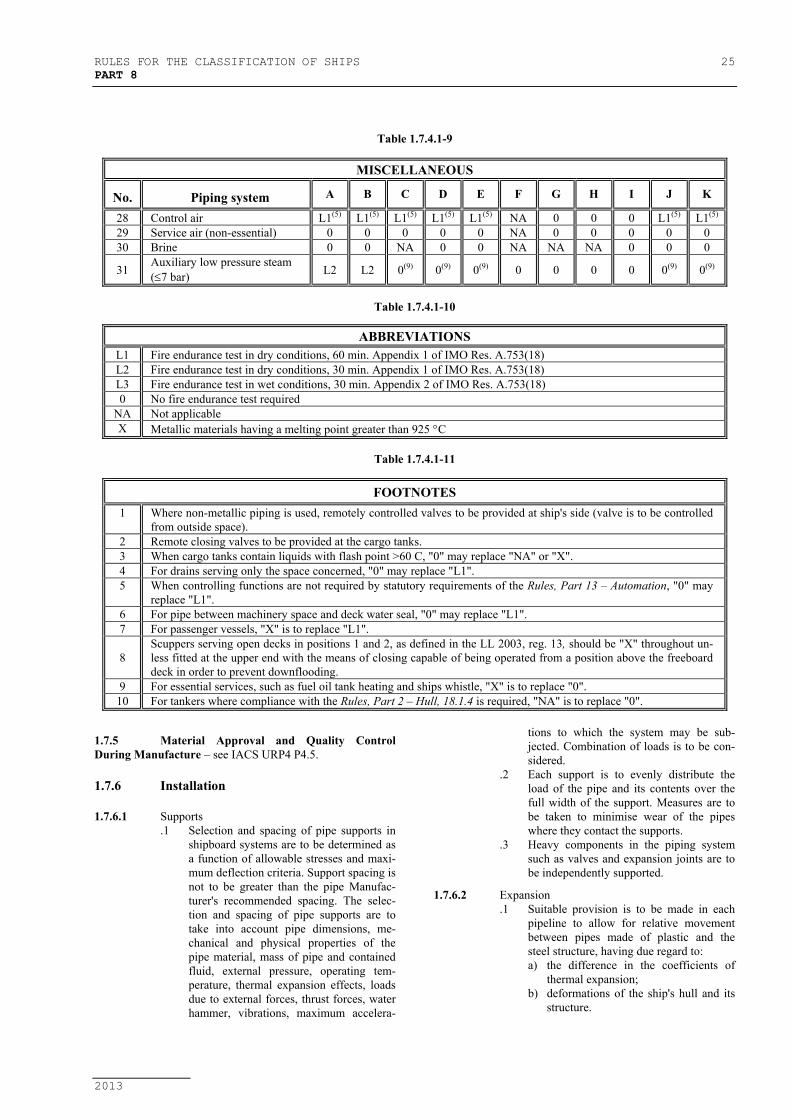
RULES FOR THE CLASSIFICATION OF SHIPS 25PART 8
2013
Table 1.7.4.1-9
MISCELLANEOUS
No. Piping system A B C D E F G H I J K
28 Control air L1(5) L1(5) L1(5) L1(5) L1(5) NA 0 0 0 L1(5) L1(5)
29 Service air (non-essential) 0 0 0 0 0 NA 0 0 0 0 030 Brine 0 0 NA 0 0 NA NA NA 0 0 0
31Auxiliary low pressure steam(≤7 bar) L2 L2 0(9) 0(9) 0(9) 0 0 0 0 0(9) 0(9)
Table 1.7.4.1-10
ABBREVIATIONSL1 Fire endurance test in dry conditions, 60 min. Appendix 1 of IMO Res. A.753(18)L2 Fire endurance test in dry conditions, 30 min. Appendix 1 of IMO Res. A.753(18)L3 Fire endurance test in wet conditions, 30 min. Appendix 2 of IMO Res. A.753(18)0 No fire endurance test required
NA Not applicableX Metallic materials having a melting point greater than 925 °C
Table 1.7.4.1-11
FOOTNOTES1 Where non-metallic piping is used, remotely controlled valves to be provided at ship's side (valve is to be controlled
from outside space).2 Remote closing valves to be provided at the cargo tanks.3 When cargo tanks contain liquids with flash point >60 C, "0" may replace "NA" or "X".4 For drains serving only the space concerned, "0" may replace "L1".5 When controlling functions are not required by statutory requirements of the Rules, Part 13 – Automation, "0" may
replace "L1".6 For pipe between machinery space and deck water seal, "0" may replace "L1".7 For passenger vessels, "X" is to replace "L1".
8Scuppers serving open decks in positions 1 and 2, as defined in the LL 2003, reg. 13, should be "X" throughout un-less fitted at the upper end with the means of closing capable of being operated from a position above the freeboarddeck in order to prevent downflooding.
9 For essential services, such as fuel oil tank heating and ships whistle, "X" is to replace "0".10 For tankers where compliance with the Rules, Part 2 – Hull, 18.1.4 is required, "NA" is to replace "0".
1.7.5 Material Approval and Quality ControlDuring Manufacture – see IACS URP4 P4.5.
1.7.6 Installation
1.7.6.1 Supports.1 Selection and spacing of pipe supports in
shipboard systems are to be determined asa function of allowable stresses and maxi-mum deflection criteria. Support spacing isnot to be greater than the pipe Manufac-turer's recommended spacing. The selec-tion and spacing of pipe supports are totake into account pipe dimensions, me-chanical and physical properties of thepipe material, mass of pipe and containedfluid, external pressure, operating tem-perature, thermal expansion effects, loadsdue to external forces, thrust forces, waterhammer, vibrations, maximum accelera-
tions to which the system may be sub-jected. Combination of loads is to be con-sidered.
.2 Each support is to evenly distribute theload of the pipe and its contents over thefull width of the support. Measures are tobe taken to minimise wear of the pipeswhere they contact the supports.
.3 Heavy components in the piping systemsuch as valves and expansion joints are tobe independently supported.
1.7.6.2 Expansion.1 Suitable provision is to be made in each
pipeline to allow for relative movementbetween pipes made of plastic and thesteel structure, having due regard to:a) the difference in the coefficients of
thermal expansion;b) deformations of the ship's hull and its
structure.
26 RULES FOR THE CLASSIFICATION OF SHIPSPART 8
2013
.2 When calculating the thermal expansions,account is to be taken of the systemworking temperature and the temperatureat which assembly is performed.
1.7.6.3 External Loads.1 When installing the piping, allowance is to
be made for temporary point loads, whereapplicable. Such allowances are to includeat least the force exerted by a load (per-son) of 100 kg at mid-span on any pipe ofmore than 100 mm nominal outside di-ameter.
.2 Besides for providing adequate robustnessfor all piping including open-ended pipinga minimum wall thickness, complyingwith 1.7.3.1, may be increased upon thedemand of the Register taking into accountthe conditions encountered during serviceon board ships.
.3 Pipes are to be protected from mechanicaldamage where necessary.
1.7.6.4 Strength of Connections.1 The strength of connections is to be not
less than that of the piping system inwhich they are installed.
.2 Pipes may be assembled using adhesive-bonded, welded, and flanged or otherjoints.
.3 Adhesives, when used for joint assembly,are to be suitable for providing a perma-nent seal between the pipes and fittingsthroughout the temperature and pressurerange of the intended application.
.4 Tightening of joints is to be performed inaccordance with Manufacturer's instruc-tions.
1.7.6.5 Installation of Conductive Pipes.1 In piping systems for fluids with conduc-
tivity less than 1000 pico siemens per me-tre (pS/m) such as refined products anddistillates use is to be made of conductivepipes.
.2 Regardless of the fluid being conveyed,plastic piping is to be electrically conduc-tive if the piping passes through a hazard-ous area. The resistance to earth from anypoint in the piping system is not to exceed1 x 10 6 Ohm. It is preferred that pipes andfittings be homogeneously conductive.Pipes and fittings having conductive layersare to be protected against a possibility ofspark damage to the pipe wall. Satisfactoryearthing is to be provided.
.3 After completion of the installation, the re-sistance to earth is to be verified. Earthingwires are to be accessible for inspection.
1.7.6.6 Application of Fire Protection Coatings.1 Fire protection coatings are to be applied
on the joints, where necessary for meetingthe required fire endurance as for 1.7.3.4,
after performing hydrostatic pressure testsof the piping system.
.2 The fire protection coatings are to be ap-plied in accordance with Manufacturer'srecommendations, using a procedure ap-proved in each particular case.
1.7.6.7 Penetration of Divisions.1 Where plastic pipes pass through "A" or
"B" class divisions, arrangements are to bemade to ensure that the fire endurance isnot impaired. These arrangements are tobe tested in accordance with Recommen-dations for fire test procedures for "A","B" and "F" bulkheads (ResolutionA.754(18) as amended).
.2 When plastic pipes pass through watertightbulkheads or decks, the watertight integ-rity of the bulkhead or deck is to be main-tained.
.3 If the bulkhead or deck is also a fire divi-sion and destruction by fire of plastic pipesmay cause the inflow of liquid from tanks,a metallic shut-off valve operable fromabove the freeboard deck should be fittedat the bulkhead or deck.
1.7.6.8 Control During Installation.1 Installation is to be in accordance with the
Manufacturer's guidelines..2 Prior to commencing the work, joining
techniques are to be approved by the Clas-sification Society.
.3 The tests and examinations specified inthis UR are to be completed before ship-board piping installation commences.
.4 The personnel performing this work is tobe properly qualified and certified to thesatisfaction of the Classification Society.
.5 The procedure of making bonds is to in-clude:a) Materials used,b) Tools and fixtures,c) Joint preparation requirements,d) Cure temperature,e) Dimensional requirements and toler-
ances, andf) Tests acceptance criteria upon com-
pletion of the assembly..6 Any change in the bonding procedure,
which will affect the physical and me-chanical properties of the joint, is to re-quire the procedure to be requalified.
1.7.6.9 Bonding Procedure Quality Testing.1 A test assembly is to be fabricated in ac-
cordance with the procedure to be quali-fied and it is to consist of at least one pipe-to-pipe joint and one pipe-to-fitting joint.
.2 When the test assembly has been cured, itis to be subjected to a hydrostatic testpressure at a safety factor 2,5 times the de-sign pressure of the test assembly, for notless than one hour. No leakage or separa-

RULES FOR THE CLASSIFICATION OF SHIPS 27PART 8
2013
tion of joints is allowed. The test is to beconducted so that the joint is loaded inboth longitudinal and circumferential di-rections.
.3 Selecting of the pipes used for test assem-bly, is to be in accordance with the fol-lowing:a) When the largest size to be joined is
200 mm nominal outside diameter, orsmaller, the test assembly is to be thelargest piping size to be joined.
b) When the largest size to be joined isgreater than 200 mm nominal outsidediameter, the size of the test assemblyis to be either 200 mm or 25% of thelargest piping size to be joined, which-ever is greater.
.4 When conducting performance qualifica-tions, each bonder and each bonding op-erator are to make up test assemblies, thesize and number of which are to be as re-quired above.
1.8 FLOW VELOCITY IN PIPINGSYSTEMS
1.8.1 Flow velocity should be carefully assessed at thedesign stage and the materials of pipes, valves etc., selected tosuit the conditions.
1.8.2.1 Standard velocities in sea water system areshown in Figure 1.8.2.1
1.7.6.10 Testing After Installation on Board.1 Piping systems for essential services are to
be subjected to a test pressure not less than1.5 times the design pressure or 4 barwhichever is greater.
.2 Piping systems for non-essential servicesare to be checked for leakage under opera-tional conditions.
.3 For piping required to be electrically con-ductive, earthing is to be checked and ran-dom resistance testing is to be conducted.
1.7.6.11 Test specification for plastic pipesThese rules contain requirements of IACS
URP4, P4.7, for the Type Approval of plastic pipes. It is ap-plicable to rigid pipe joints and fittings.The requirements are to be uniformly implemented to any newplastic pipe submitted for approval from 1 January 2007 andto any existing plastic pipe from the date of the first renewalof approval after 1 January 2007.
1.8.2 The water velocity in copper pipes should notexceed 1 m/s, but in the pipes of materials listed below thewater (sea water and fresh water) velocity should normally benot less than about 1 m/s in order to avoid fouling and subse-quent pitting:
For pipelines in sea water systems, the recom-mended velocities at continuos flow are shown on the diagramFigure 1.8.2.1, with respect to the material and nominal di-ameter of pipe (ND mm).
Figure 1.8.2.1
Where:
A – Cast iron pipesB – 70/30 copper-nickel pipes (CuNi30Mn1Fe)C – 90/10 copper-nickel-iron pipes (CuNi10Fe1Mn)D – Galvanised steel pipes and Aluminium brass pipes
(CuZn21Al2-Yorcalbro)
In accordance with good shipbuilding practice, standard flowvelocities (v m/s), with respect to the nominal diameter ofpipe (ND mm), are shown in the diagrams Figure 1.8.3.1,1.8.3.2, 1.8.3.3 and 1.8.3.4. The diagrams are recommendedas a reference generally for pipeline design in other pipelinesystems on the ships.
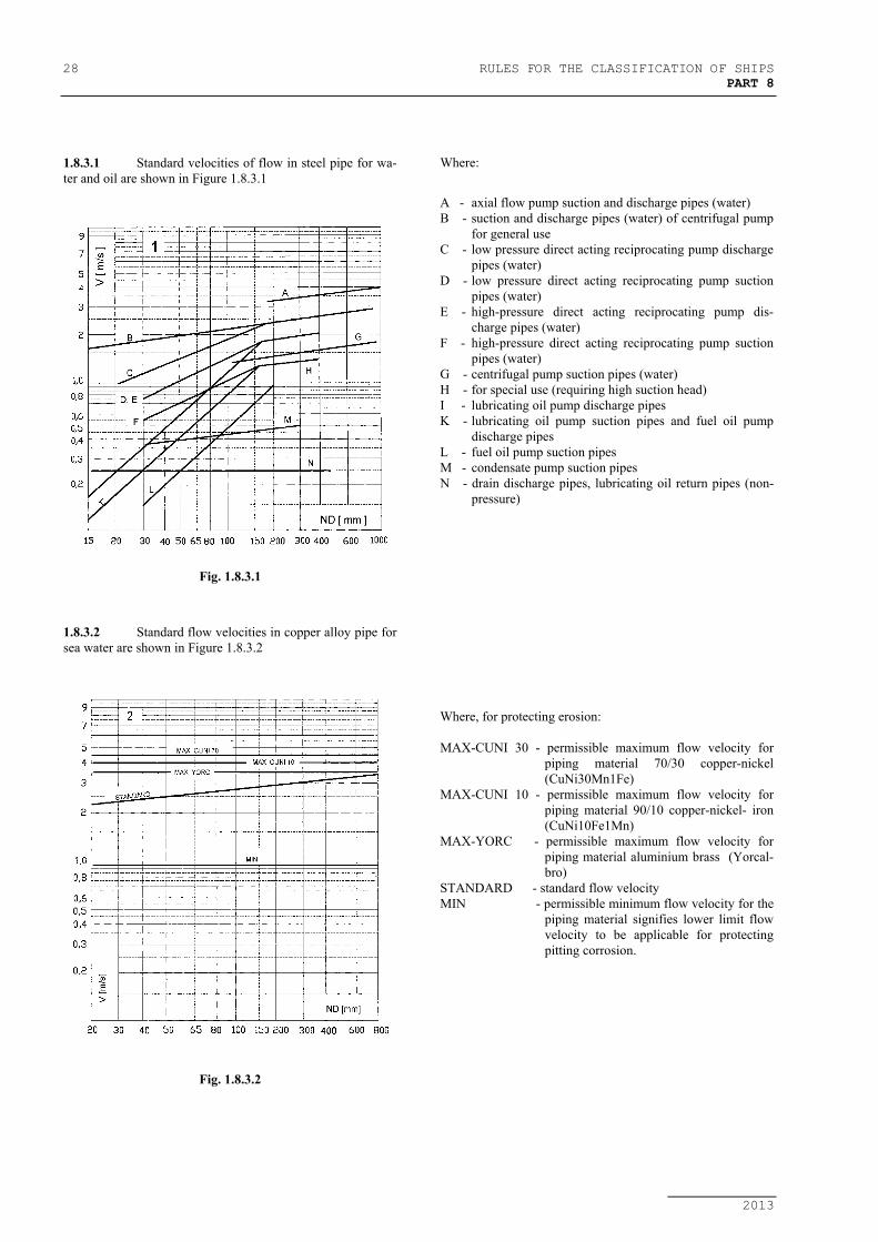
28 RULES FOR THE CLASSIFICATION OF SHIPSPART 8
2013
1.8.3.1 Standard velocities of flow in steel pipe for wa-ter and oil are shown in Figure 1.8.3.1
Fig. 1.8.3.1
Where:
A - axial flow pump suction and discharge pipes (water)B - suction and discharge pipes (water) of centrifugal pump
for general useC - low pressure direct acting reciprocating pump discharge
pipes (water)D - low pressure direct acting reciprocating pump suction
pipes (water)E - high-pressure direct acting reciprocating pump dis-
charge pipes (water)F - high-pressure direct acting reciprocating pump suction
pipes (water)G - centrifugal pump suction pipes (water)H - for special use (requiring high suction head)I - lubricating oil pump discharge pipesK - lubricating oil pump suction pipes and fuel oil pump
discharge pipesL - fuel oil pump suction pipesM - condensate pump suction pipesN - drain discharge pipes, lubricating oil return pipes (non-
pressure)
1.8.3.2 Standard flow velocities in copper alloy pipe forsea water are shown in Figure 1.8.3.2
Fig. 1.8.3.2
Where, for protecting erosion:
MAX-CUNI 30 - permissible maximum flow velocity forpiping material 70/30 copper-nickel(CuNi30Mn1Fe)
MAX-CUNI 10 - permissible maximum flow velocity forpiping material 90/10 copper-nickel- iron(CuNi10Fe1Mn)
MAX-YORC - permissible maximum flow velocity forpiping material aluminium brass (Yorcal-bro)
STANDARD - standard flow velocityMIN - permissible minimum flow velocity for the
piping material signifies lower limit flowvelocity to be applicable for protectingpitting corrosion.

RULES FOR THE CLASSIFICATION OF SHIPS 29PART 8
2013
1.8.3.3 Standard flow velocities in steel pipe for exhaustgas are shown in Figure 1.8.3.3
Fig. 1.8.3.3
Where:
DE - diesel engine without exhaust gas economiserDE / EGB - diesel engine with exhaust gas economiserINC - waste oil incineratorAB - auxiliary boiler
1.8.3.4 Standard flow velocities in steam, exhaust andcompressed air pipes are shown in Figure 1.8.3.4
Fig. 1.8.3.4
Where:
EX-AUXT/RE - exhaust pipes for auxiliary turbine (super-heated) and for reciprocating engine
ST / EX-AUXT - steam pipes (superheated) and exhaustpipes for auxiliary turbine
ST / MAST -steam pipes (superheated) for main asternturbine
ST-AT / RE - steam pipes (saturated) for auxiliary tur-bine and exhaust pipes for reciprocatingengine
ST-MAHT - steam pipes (superheated) for main aheadturbine
CA - compressed air pipesVENT - ducted pipes for ventilation

30 RULES FOR THE CLASSIFICATION OF SHIPSPART 8
2013
1.9 MACHINERY AND AUTOMATEDINSTALLATIONS
1.9.1 Pumps, fans, compressors and their electricdrives used in systems which are described in this Part ofRules shall comply with the requirements of the Rules, Part 9- Machinery and Part 12 - Electrical Equipment.
1.9.2 Automation systems shall comply with the re-quirements of the Rules, Part 13 - Automation.
1.9.3 Heat exchangers and pressure vessels used inpiping systems are to comply with the requirements of theRules, Part 10 - Boilers, Heat Exchangers and Pressure Ves-sels.
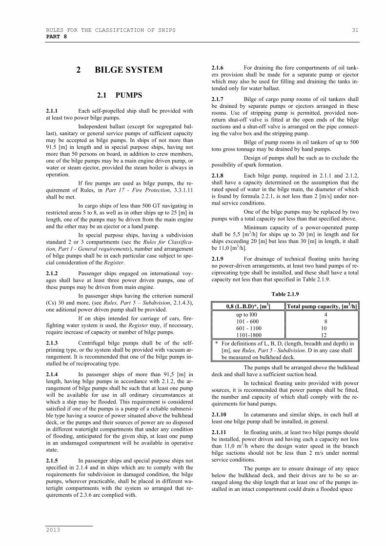
RULES FOR THE CLASSIFICATION OF SHIPS 31PART 8
2013
2 BILGE SYSTEM
2.1 PUMPS
2.1.1 Each self-propelled ship shall be provided withat least two power bilge pumps.
Independent ballast (except for segregated bal-last), sanitary or general service pumps of sufficient capacitymay be accepted as bilge pumps. In ships of not more than91.5 [m] in length and in special purpose ships, having notmore than 50 persons on board, in addition to crew members,one of the bilge pumps may be a main engine driven pump, orwater or steam ejector, provided the steam boiler is always inoperation.
If fire pumps are used as bilge pumps, the re-quirement of Rules, in Part 17 - Fire Protection, 3.3.1.11shall be met.
In cargo ships of less than 500 GT navigating inrestricted areas 5 to 8, as well as in other ships up to 25 [m] inlength, one of the pumps may be driven from the main engineand the other may be an ejector or a hand pump.
In special purpose ships, having a subdivisionstandard 2 or 3 compartments (see the Rules for Classifica-tion, Part 1 - General requirements), number and arrangementof bilge pumps shall be in each particular case subject to spe-cial consideration of the Register.
2.1.2 Passenger ships engaged on international voy-ages shall have at least three power driven pumps, one ofthese pumps may be driven from main engine.
In passenger ships having the criterion numeral(Cs) 30 and more, (see Rules, Part 5 – Subdivision, 2.1.4.3),one aditional power driven pump shall be provided.
If on ships intended for carriage of cars, fire-fighting water system is used, the Register may, if necessary,require increase of capacity or number of bilge pumps.
2.1.3 Centrifugal bilge pumps shall be of the self-priming type, or the system shall be provided with vacuum ar-rangement. It is recommended that one of the bilge pumps in-stalled be of reciprocating type.
2.1.4 In passenger ships of more than 91,5 [m] inlength, having bilge pumps in accordance with 2.1.2, the ar-rangement of bilge pumps shall be such that at least one pumpwill be available for use in all ordinary circumstances atwhich a ship may be flooded. This requirement is consideredsatisfied if one of the pumps is a pump of a reliable submersi-ble type having a source of power situated above the bulkheaddeck, or the pumps and their sources of power are so disposedin different watertight compartments that under any conditionof flooding, anticipated for the given ship, at least one pumpin an undamaged compartment will be available in operativestate.
2.1.5 In passenger ships and special purpose ships notspecified in 2.1.4 and in ships which are to comply with therequirements for subdivision in damaged condition, the bilgepumps, wherever practicable, shall be placed in different wa-tertight compartments with the system so arranged that re-quirements of 2.3.6 are complied with.
2.1.6 For draining the fore compartments of oil tank-ers provision shall be made for a separate pump or ejectorwhich may also be used for filling and draining the tanks in-tended only for water ballast.
2.1.7 Bilge of cargo pump rooms of oil tankers shallbe drained by separate pumps or ejectors arranged in theserooms. Use of stripping pump is permitted, provided non-return shut-off valve is fitted at the open ends of the bilgesuctions and a shut-off valve is arranged on the pipe connect-ing the valve box and the stripping pump.
Bilge of pump rooms in oil tankers of up to 500tons gross tonnage may be drained by hand pumps.
Design of pumps shall be such as to exclude thepossibility of spark formation.
2.1.8 Each bilge pump, required in 2.1.1 and 2.1.2,shall have a capacity determined on the assumption that therated speed of water in the bilge main, the diameter of whichis found by formula 2.2.1, is not less than 2 [m/s] under nor-mal service conditions.
One of the bilge pumps may be replaced by twopumps with a total capacity not less than that specified above.
Minimum capacity of a power-operated pumpshall be 5,5 [m3/h] for ships up to 20 [m] in length and forships exceeding 20 [m] but less than 30 [m] in length, it shallbe 11,0 [m3/h].
2.1.9 For drainage of technical floating units havingno power-driven arrangements, at least two hand pumps of re-ciprocating type shall be installed, and these shall have a totalcapacity not less than that specified in Table 2.1.9.
Table 2.1.9
0,8 (L.B.D)*, [m3] Total pump capacity, [m3/h]up to l00 4101 - 600 8601 - 1100 101101-1800 12
* For definitions of L, B, D, (length, breadth and depth) in[m], see Rules, Part 5 - Subdivision. D in any case shallbe measured on bulkhead deck.
The pumps shall be arranged above the bulkheaddeck and shall have a sufficient suction head.
In technical floating units provided with powersources, it is recommended that power pumps shall be fitted,the number and capacity of which shall comply with the re-quirements for hand pumps.
2.1.10 In catamarans and similar ships, in each hull atleast one bilge pump shall be installed, in general.
2.1.11 In floating units, at least two bilge pumps shouldbe installed, power driven and having each a capacity not lessthan 11,0 m3/h where the design water speed in the branchbilge suctions should not be less than 2 m/s under normalservice conditions.
The pumps are to ensure drainage of any spacebelow the bulkhead deck, and their drives are to be so ar-ranged along the ship length that at least one of the pumps in-stalled in an intact compartment could drain a flooded space

32 RULES FOR THE CLASSIFICATION OF SHIPSPART 8
2013
2.2 PIPE DIAMETERS
2.2.1 Internal diameter d1 of the bilge main and of di-rect suctions from the pump, except for the case specified in2.2.3, shall not be less than diameter determined by the for-mula:
d1 = 1,68 ( )DBL + + 25 [mm] (2.2.1-1)
In vessels of dredging fleet having hopperspaces, the internal diameter of the bilge main and direct suc-tions from the pump, shall be determined by the formula:
d1 = 1,68 ( ) ( )DblDBL +−+ 1 + 25 [mm] (2.2.1-2)
where:l1 − length of hopper space, [m]b − mean width of hopper space, [m]L, B, D − see 2.1.9.
2.2.2 Internal diameter do of branch bilge suctionsconnected to the bilge main and the diameter of the suctionpipe of the hand pump, shall not be less than the diameter de-termined by formula:
do = 2,15 ( )DBl + + 25[mm] (2.2.2)
where:l − length of the compartment to be drained,
measured at its bottom, [m].B, D − see 2.1.9.
2.2.3 The inside diameter of main and branch bilgepipes is not to be less than 50 mm. For ships under 25 mlength, the diameter may be reduced to 40 mm.
Internal diameter of the bilge main and thebranch suctions which are directly connected to the bilgepump shall not be in any case less than diameter of suctions ofthe bilge pump suction.
2.2.4 Cross-sectional area of the pipe, connecting thedistribution box with the bilge main shall not be less than thetotal cross-sectional area of two largest bilge suctions con-nected to the box, but it shall not be greater than the sectionalarea of the bilge main.
2.2.5 In oil tankers and other ships in which bilgepumps are intended for draining only the engine room, thecross-sectional area of the bilge main shall be not less thantwice the cross-sectional area of the branch suction, the di-ameter of which is determined by formula 2.2.2.
2.2.6 Diameters of the suctions for emergency drain-age of the engine room shall be determined as per 2.3.8.
2.3 PIPING ARRANGEMENT
2.3.1 Bilge lines and their branch suctions shall be soarranged as to enable any watertight compartment to bedrained by one of the pumps required in 2.1.1 and 2.1.2. Thisrequirement does not apply neither to the spaces of ammoniarefrigerating machinery, peaks, pump rooms and cofferdamsof oil tankers, drained by individual pumps, nor to the tanksintended only for storage of liquids. Where the spaces are not
fitted with bilge suctions, other means for draining water shallbe provided.
2.3.2 Bilge pumping system shall be so arranged as toprevent the possibility of sea water passing inside the ship, orfrom one watertight compartment into another. For this pur-pose the suction valves of the distribution chests of the bilgepipes, as well as the valves of the branch suctions connecteddirectly to the main, are to be of screw-down non-return type.
Other equivalent arrangements are allowed.
2.3.3 The arrangement of bilge pipes is to be such aeto ensure the possibility of draining the engine rooms throughthe suctions directly connected to the pump, the other com-partments being simultaneously drained by other pumps.
2.3.4 The arrangement of bilge pipes shall be such asto enable one of the pumps to be operated in case the rest ofthe pumps are inoperative or are used for other purposes. Suc-tion branches of bilge pipelines shall be independent of otherpiping systems, up to the connections to the pumps.
2.3.5 In ships which are to comply with the require-ments for subdivision in damaged condition, the bilge suctionpipes, which are with one part situated nearer to the ship's sidethan 1/5 of the breadth of the ship (measured at right angles tothe centerline at the level of the deepest subdivision load line),as well as when the piping extending inside the duct keel ordouble bottom, shall have non-return valves fitted to theirbranch suctions in each watertight compartment.
2.3.6 In passenger ships of more than 91.5 [m] inlength or in special purpose ships having more than 50 per-sons, in addition to crew members or having subdivision indexR greater than 0,5, all distribution chests, cocks and valves as-sociated with the bilge pumping system shall be so arrangedthat in the event of flooding, one of the bilge pumps can beoperative on any flooded compartment. Moreover, damage ofpump or piping system connected to the bilge main outboardof a line drawn at one-fifth of the breadth of the ship shall notput the bilge system out of action.
Where there is only one system of pipes com-mon to all the pumps, the necessary cocks and valves for con-trolling the bilge suctions shall be fitted with means enablingthem to be controlled from above the bulkhead deck. Theyshall be fitted, at control places, with the equipment for indi-cation of purpose and open-close position. Where, in additionto the main bilge pumping system, an emergency bilge systemis provided, it shall be independent of the main system andshall be so arranged that a pump is capable of operating onany compartment under flooding conditions. In this case, onlycocks and valves required for controlling the emergency sys-tem need be suited for being operated from above the bulk-head deck, while the pump and associated suction pipes shallbe situated farther from the ship's side than 1/5 of the breadthof the ship.
2.3.7 As a rule, bilge pipes shall be led outside thedouble bottom. Where it is necessary to lead these pipesthrough the tanks for storage of fuel oil, lubricating oil, boilerfeed water and drinking water, the pipes shall meet the re-quirements of 1.6.2.1.
Where the pipes are led through the double bot-tom, the suction pipes in each watertight compartment shall befitted with non-return valves.

RULES FOR THE CLASSIFICATION OF SHIPS 33PART 8
2013
2.3.8 In all self-propelled ships provision shall bemade for emergency drainage of the engine rooms, in additionto the suction branches required by 2.4.1 and 2.4.4.
For this purpose one of the main circulatingpumps in steam ships, and the pump of maximum capacity inmotor ships, shall be fitted with direct suction branches withnon-return shut-off valves on the level which assures the en-gine room to be drained. The diameter of this direct suctionbranches shall be at least 2/3 of the diameter of the pump inletin steam ships, and shall be at least equal to the diameter ofthe pump suction in motor ships.Where the pumps specified above are not suitable for emer-gency drainage, a direct emergency bilge suction branch shallbe connected to the largest available independent power pumpnot intended for drainage.The capacity of this pump shall exceed that required in 2.1.8by an amount satisfactory to the Register. The diameter of thesuction emergency branches shall not be less than that of thepump suction.Hand control wheel for non-return shut-off valves fitted to thesuction branches shall be fitted above the engine room floor-ing to a sufficient height and shall have name plate “Emer-gency drainage only”.
In cargo ships of less than 500 GT navigating inrestricted areas 5 to 8, passenger ships navigating in restrictedareas 8, as well as in other ships up to 25 [m] in length, emer-gency drainage system of machinery spaces may be dispensedwith.
2.3.9 Before overboard discharge, oily water shall beseparated. For this purpose the ship shall be provided withoily water separating equipment. Installation and operation ofsuch equipment shall not interfere with normal working of thebilge and ballast systems indicated in 8.1.2.
2.4 DRAINAGE OF MACHINERYSPACES
2.4.1 Where engines and boilers are located in thesame compartment and the double bottom either form bilges atthe wings, or extends the full breadth of the compartment, it isnecessary to provide two bilge suctions at each side near thebulkheads, one of which shall be directly connected to an in-dependent bilge pump.
2.4.2 Where the engines and boilers are located in thesame compartment with no double bottom, and the raise offloors is not less than 5o, two bilge suctions shall be provided,one of which shall be directly connected to an independentbilge pump.
Where the raise of floor, towards the ship's side,is less than 5o, two additional bilge suctions, one at each side,shall be fitted and connected to the bilge main.
2.4.3 Where the engines and boilers as well as theauxiliaries or electric propulsion motors, are located in sepa-rate watertight compartments, number and position of bilgesuctions therein shall be adopted as set forth in 2.6. In shipswhich are to comply with the requirements for subdivision indamaged condition, each of these compartments shall be fittedwith an additional bilge suction direct-connected to an inde-pendent bilge pump.
In passenger ships each of independent pumpslocated in the machinery spaces shall have direct suctions inthese spaces. More than two such suctions are not required forthese spaces. Where two or more such suctions are fitted, atleast one of them shall be located on each side.
The independent power pump located in otherspaces, may have direct suction in these spaces.
2.4.4 Where the machinery space is situated at the af-ter end of the ship, bilge suctions shall be fitted in the forwardwings of the space. Depending on the shape of the after end,the Register may require the installment of one or two suctionbranches in the after end of the ship.
2.4.5 Suctions for bilge drainage of machinery spacesand shaft tunnels shall be fitted with readily accessible mudboxes. Pipes between mud boxes and bilge wells shall be asstraight as possible. The lower ends of these pipes shall not befitted with strums.
Mud boxes shall have covers that can be easilyopened.
In ships less than 500 GT navigating in re-stricted areas 5 to 8, instead of mud boxes, strum boxes maybe used, provided they are accessible for cleaning.
2.4.6 No strum boxes or strainers shall be fitted on thesuction for emergency bilge drainage.
2.4.7 Where there is a double bottom, machineryspaces shall be fitted with bilge wells of a capacity not lessthan 0,20 m3.
2.4.8 Additional suction branches shall be installed inthe log and echo sounder trunks, as well as in the double-bottom wells under the machinery and in other places whichmay accumulate water.
2.4.9 Ships having an electric propulsion installationshall be provided with arrangement for proper drainage of thewells under the main generator and propulsion motor, as wellas with automatic alarms to give warning at excess of permis-sible water level in the wells.
Automatic drainage of wells under main gen-erators and propulsion motors is recommended to be used.
2.4.10 Space of ammonia refrigerating machinery shallhave an independent bilge system. Where a water sprayingsystem is provided in this space, capacity of the bilge pumpshall not be less than the capacity of the water spraying sys-tem pump. The discharge pipe of the bilge system shall be leddirectly overboard.
Bilge suctions of the space for freon refrigerat-ing machinery may be connected to the bilge main of the ship.
2.5 DRAINAGE OF TUNNELS
2.5.1 Each shaft tunnel and each pipe tunnel shallhave the bilge suction branch, from the well in the after part ofthe tunnel, connected to the bilge main.
Where required, additional suctions may be pro-vided in the fore part of the tunnel
Bilge suctions of the shaft tunnel shall be madein compliance with the requirements set forth in 2.4.5.

34 RULES FOR THE CLASSIFICATION OF SHIPSPART 8
2013
2.6 DRAINAGE OF CARGO HOLDS
2.6.1 Each cargo hold, where the double bottom formsbilges at the wings, shall have at least one bilge suction in theafter part of the hold at each side of the ship.
2.6.2 Where the double bottom extends in the fullbreadth of the cargo hold, bilge wells shall be provided in theafter part of the hold at each side.
The capacity of the wells shall comply with re-quirements of 2.4.7.
2.6.3 In holds with double bottom where the innerbottom plating has inverse camber, provision shall be madealso for suctions at the centre line, in addition to the suctionssituated at the wings. Where a bilge well extends over the en-tire breadth of the hold, and the inverse camber exceeds 5o,only one branch suction may be led to this well.
2.6.4 Where manholes for access to bilge wells areprovided, they shall be arranged as near to the bilge suction aspossible.
2.6.5 In each cargo hold where there is no doublebottom and the raise of floor in the hold exceeds 5o, one bilgesuction near the centerline of the ship will be sufficient. If therise of the floor is less than 5o, at least two suctions shall befitted, one at each side of the hold.
2.6.6 Where the length of a hold exceeds 35 m, bilgesuctions shall be installed in the fore and the after parts of thishold, the requirements of 2.6.1 to 2.6.5 being complied with.
2.6.7 At narrow ends of cargo holds a single bilgesuction may be allowed.
2.6.8 Drain pipes from spaces located below the bulk-head deck and communicating with the cargo hold in the samecompartment are permitted to be led into the wells of the hold.
Discharge of bilge water into the wells of acargo hold from watertight spaces located below the bulkiheaddeck is not permitted.
For discharge of bilge water into bilges of re-frigerated cargo spaces, see 2.7.
2.6.9 Where a ceiling or removable covers are fittedover the bilges or wells in cargo holds, provision shall bemade for free access of water into the bilges or wells.
2.6.10 Branch bilge suctions shall be fitted with strumboxes, or strainers having perforations 8-10 [mm] in diameter.
Total area of these perforations shall not be lessthan twice the clear area of the given suction pipe.
Strum boxes and strainers shall be removable, orprovision shall be made for cleaning them without disassem-bling any connection of suction branch.
2.6.11 In bulk carrier holds the bilge system shall be sodesigned that its operability may not be affected when bulkcargo is carried.
2.6.12 Cargo holds above bulkhead decks of passengerships, or cargo ship that is assigned a subdivision distinguish-ing mark in its class notation, and on the freeboard deck of thecargo ship, are to be fitted with drainage arrangements speci-fied under 2.6.12.1 and 2.6.12.2
2.6.12.1 Closed cargo holds may be drained directly tooverboard, only when at a heel of the ship of 5°, the edge ofthe bulkhead deck or freeboard deck shall not be immersedbelow the water line. The scuppers and drain pipes shall be ar-ranged and fitted according to 1.5.2.11 of the present Part.
2.6.12.2 Where the edge of the deck touches the waterline or is already immersed when the ship heels 5°, the drain-age shall be led to one or more drain tanks of adequate capac-ity. The drainage tanks are to be fitted with a high water levelalarm and provided with suitable arrangements for dischargeoverboard. In such cases it shall be ensured that:
.1 the number, size and disposition of thescuppers are such as to prevent unreason-able accumulation of free water;
.2 the above mentioned pumping arrange-ments for the drainage of the cargo spacesprovide water drainage with any fixedwater fire-extinguishing systems, includ-ing spraying systems, that are required, re-spectively, for passenger and cargo ships;
.3 water contaminated with petrol or otherdangerous substances is not drained to ma-chinery spaces or other spaces containingsources of ignition;
.4 where the enclosed cargo spaces are pro-tected by a fire smothering system thedeck scuppers are fitted with means toprevent the escape of the gas.
2.6.13 Bilge alarms should be provided in each holdfitted with non-weathertight covers.
2.7 DRAINAGE OF REFRIGERATEDCARGO SPACES
2.7.1 Provision shall be made for draining all thespaces, trays, chutes and other places which may accumulatewater.
2.7.2 Drain pipes from non-refrigerated spaces are notpermitted to be led into the bilges of refrigerated spaces.
2.7.3 Each drain pipe of refrigerated cargo spacesshall be fitted with a liquid sealed trap or with anotherequivalent arrangement. The head of liquid shall be such thatthe arrangement will work effectively under any service con-ditions.
Liquid sealed traps shall be placed in accessiblepositions outside the insulation. Where drain pipes from thetween deck spaces and the hold are led into a common bilgewell, non-return valves shall be fitted to the ends of the drainsfrom the hold.
2.7.4 As a rule, no shut-off valves shall be fitted onthe drain pipes from refrigerated spaces.
2.8 DRAINAGE OF DEEP TANKS
2.8.1 Deep tanks used also for carriage of dry cargoshall be fitted with bilge suctions and with effective shut-offmeans isolating ballast and oil lines from the deep tanks and

RULES FOR THE CLASSIFICATION OF SHIPS 35PART 8
2013
isolating bilge line when fuel oil or ballast are carried in thetanks.
The arrangement of the bilge suctions is to com-ply with the requirements of 2.6.
2.9 DRAINAGE OF COFFERDAMS
2.9.1 Cofferdams filled with water shall be providedwith a drainage facility. The arrangement of branch suctionsin cofferdams shall be comply with requirements of 2.6.
2.9.2 In tankers and multi-purpose ships the filled cof-ferdams, adjoining the cargo tanks or slop tanks, shall haveindependent drain arrangements.
2.10 DRAINAGE OF FORE AND AFTERPEAK
2.10.1 Where the peaks are not used as water ballasttanks or as other tanks, independent drainage by hand pumpsor water ejectors may be provided.
For ships of 500 tonnage and over, with servicenotation bulk carrier, ore carrier or combination carrier, seespecific requirements 2.12.
2.11 DRAINAGE OF OTHER SPACES
2.11.1 Drainage of chain lockers and boatswain's storesmay be carried out by means of hand pumps, water ejectors orother means.
2.11.2 Drainage of steering engine rooms and othercompartments situated above the afterpeak may be carried outby special hand pumps or water ejectors, as well as throughdrain pipes led into the bilges of engine room or shaft tunnel.
Drain pipes shall be fitted with readily accessi-ble self-closing valves. The internal diameter of these valvesshall be not less than 39 [mm].
In passenger ships, drain pipes shall not be usedfor drainage of the above-mentioned spaces.
2.11.3 Drain pipes shall not be led into the bilges ofengine rooms and shaft tunnels from the adjacent spaces situ-ated in other watertight compartments below the bulkheaddeck. This does not apply to the cases specified in 2.11.2.
Drain pipes from these spaces may be led intothe engine rooms and shaft tunnels only if terminating intoclosed drain tanks.
Where several watertight compartments have acommon drain tank, drain pipes from these compartmentsshall be fitted with non return valves.
Drainage of such tank may be carried outthrough the bilge main, provided a non-return valve is fittedon the branch suction.
2.11.4 Drain pipes from enclosed superstructures anddeckhouses may be led into bilge wells of the engine room orthe holds.
In ships which are to comply with the require-ments for subdivision in damaged condition, these pipes shall
be fitted with valves controllable from a place above the bulk-head deck.
2.11.5 Drain pipes of storerooms for explosives shall befitted with valves controllable from locations outside theserooms.
2.11.6 Closed cargo spaces intended for carriage offlammable or poisonous liquids shall be provided with inde-pendent drainage system not communicating with the machin-ery space.
The Register may permit the use of the ship’smain drainage system for the drainage of such spaces, if thedesign prevents accidental pumping of flammable or toxic liq-uids through the pipelines and pumps of the engine room
2.11.7 In cargo pump rooms on oil tankers, the follow-ing requirements are included in the measures to prevent ex-plosion:
.1 High liquid level in the bilges shall acti-vate an audible and visual alarm in thecargo control room and on the navigationbridge.
.2 Cargo pumps, ballast pumps and strippingpumps, installed in cargo pump rooms anddriven by shafts passing through pumproom bulkheads shall be fitted with tem-perature sensing devices for bulkheadshaft glands, bearings and pump casings.Alarm shall be initiated in the cargo con-trol room or the pump control station.
2.12 SPECIFIC REQUIREMENTS FORDRAINAGE OF FORWARD SPACES IN
BULK, ORE AND COMBINATIONCARRIERS ("dewatering system")
2.12.1 Unless otherwise specified, this requirement ap-plies to ships of 500 tonnage and over, with service notationbulk carrier, ore carrier or combination carrier, as definedby the Rules Part 1, Chapter 1, 4.2.
2.12.2 The bilge of dry spaces any part of which ex-tends forward of the foremost cargo hold, as well as the meansfor draining and pumping ballast tanks forward of the colli-sion bulkhead, is to be capable of being brought into operationfrom a readily accessible enclosed space, the location ofwhich is accessible from the navigation bridge or propulsionmachinery control position without traversing exposed free-board or superstructure decks. The following criteria are togovern the application of the requirement:
.1 A position which is accessible via an un-der deck passage, a pipe trunk or othersimilar means of access is not to be takenas being in the accessible enclosed space.
.2 The requirement does not apply to the en-closed spaces the volume of which doesnot exceed 0,1% of the ship maximumdisplacement volume and to the chainlocker.
2.12.3 The water level detectors, giving an audible andvisual alarm located on the navigation bridge, are to be fitted:

36 RULES FOR THE CLASSIFICATION OF SHIPSPART 8
2013
.1 In any ballast tank forward of the collisionbulkhead, indicating when the liquid in thetank reaches a level not exceeding 10% ofthe tank capacity. An alarm overriding de-vice may be installed to be activated whenthe tank is in use.
.2 In any dry or void space which is to com-ply with the requirements in 2.12.1, givingthe alarm at a water level of 0,1 m abovethe deck.
2.12.4 The capacity of the dewatering system is to bedesigned to remove water from the forward spaces at a rate ofnot less than 320 A [m3/h], where A is the cross-sectional areain [m2] of the largest air pipe or ventilator pipe connectedfrom the exposed deck to a closed forward space that is re-quired to be dewatered by these arrangements.
2.12.5 When dewatering systems are in operation, thefollowing is to be fulfilled:
.1 Other systems essential for the safety ofthe ship, including fire-fighting and bilgesystems, are to remain available and readyfor immediate use.
.2 It is to be possible to start fire pumps im-mediately and to have a ready availablesupply of fire-fighting water .
.3 The systems for normal operation of elec-tric power supplies, propulsion and steer-ing are not to be affected by this operation.
2.12.6 The drainage arrangements are to be such that:.1 Any accumulated water can be drained di-
rectly by a pump or an eductor..2 It should be possible to configure and use
bilge system for any compartment whenthe drainage system is in operation.
.3 Remotely operated valves within the sys-tem are to comply with the requirements1.4.1.2.
.4 Bilge wells are to be protected by gratingsor strainers to prevent blockage of thedrainage system with debris.
2.12.7 Where pipes serving tanks in forward spaces orbilge pierce the collision bulkhead, valve operation by meansof remotely operated actuators may be accepted as an alterna-tive to the valve control required in 1.6.1.2, provided that thefollowing is fulfilled:
.1 The valve required in 1.6.1.2 is to be ca-pable of being controlled from the positionas required in item 2.12.2.
.2 The valve is not to move from the de-manded position in the case of failure ofthe control system power or actuatorpower
.3 Positive indication is to be provided at theremote control station to show that thevalve is fully open or closed
.4 In addition, the local hand powered valveoperation from above the freeboard deck isalso to be provided.
2.1.12.8 The piping arrangements for drainage of closeddry spaces may be connected to the piping arrangements fordrainage of water ballast tanks, provided that:
.1 Two non-return valves are fitted to preventthe ingress of water into dry spaces fromthose intended for the carriage of waterballast.
.2 The non-return valves are located in read-ily accessible positions.
.3 One of these non-return valves is fittedwith shut-off isolation arrangement.
.4 The shut-off isolation arrangement is ca-pable of being controlled from the positionas required in item 2.12.2.

RULES FOR THE CLASSIFICATION OF SHIPS 37PART 8
2013
3 BALLAST SYSTEM
3.1 PUMPS
3.1.1 Any ship shall be provided with at least onepump for charging and discharging ballast tanks.
Capacity of the ballast pump shall be such as toensure the speed of water of not less than 2 [m/s], with thesuction pipe diameter taken from formula 3.2.1 as for the larg-est ballast tank.
3.1.2 Excluding the oil tankers, general services,bilge, fire or stand-by cooling water pumps of sufficient ca-pacity (see 3.1.3)may be used as ballast pumps.
For ballast pumps in oil tankers see 2.1.6 and4.2.2.
3.1.3 Where the oil fuel tanks are generally used asballast tanks, the standby cooling water pump or a fire pumpshall not be used for ballasting, nor shall the ballast pump beused as fire pump or standby cooling pump.
3.1.4 Pumps used for pumping out ballast water fromthe double-bottom tanks shall be of self-priming type.
3.1.5 In passenger ships, ballast tanks shall not be in-tended for carriage of fuel oil. Possible relaxations from thisrequirement, if provision is made for separators or other de-vices, shall be specially considered by the Register (see also8.1.2).
3.2 PIPE DIAMETERS
3.2.1 Internal diameter of the ballast pipes from sepa-rate tanks shall be determined by the formula
du = 18 3 V [mm] (3.2.1)
where:V − volume of the ballast tank, [m3].
The diameter, determined in this way, may beadapted to the nearest standard size.
3.2.2 The diameter of the ballast main shall be not lessthan the maximum diameter of the suction determined by theformula 3.2.1.
3.3 PIPING ARRANGEMENT
3.3.1 Arrangement of the suctions shall be such as toensure discharging of water from any of the ballast tanks, re-gardless of whether the ship is upright or listed not more than5o.
3.3.2 In ships with ice strengthening categories 1AS,and 1A the fore and after peaks as well as structural wingtanks for fresh water in way of cargo holds, shall have heatingarrangements.
It is recommended to provide heating facilitiesfor double bottom ballast tanks situated in way of cargo holds.
3.3.3 Suction and discharge pipes of clean ballasttanks shall not communicate with sea inlet boxes and pipe-lines servicing cargo tanks.
3.3.4 The fore peak tank on oil tankers may be bal-lasted with the system serving ballast tanks located withincargo area, subject to the conditions specified with the Rules,Part 17.-Fire protection, item 2.4.7.7.
3.3.5 For tankers with the integrated cargo and ballastsystems installed for operation of ballast and/or cargo sys-tems, see 4.5.
38 RULES FOR THE CLASSIFICATION OF SHIPSPART 8
2013
4 CARGO PIPING SYSTEM OFOIL TANKERS AND OIL
COLLECTING SHIPS
4.1 PUMPS AND THEIR DRIVES
4.1.1 Cargo oil pumps and cargo stripping pumpsshall serve only the direct purpose, excluding even the casesspecified in 2.1.7 and 4.2.3. These pumps shall not have anyconnections to the tanks other than cargo tanks.
Cargo oil and cargo stripping pumps shall be ar-ranged in separate spaces.
4.1.2 For the arrangement of cargo and strippingpumps driving machinery, see the Rules, Part 7 - MachineryInstallations, 1.12.6.
4.1.3 Construction of pumps, fittings and fitting driv-ing machinery, for oil with flashpoint < 60oC, shall precludethe possibility of spark formation to the maximum.
4.1.4 Arrangements shall be provided for stoppingeach cargo oil and cargo stripping pump from the top flat ofthe pump room situated at the level of the main deck or fromthe central control station for loading or unloading of cargo.Electrical stopping arrangements of the pumps shall complywith the Rules, Part 12 - Electrical Equipment, 5.7.
4.1.5 The pressure gauges of the cargo oil dischargeand cargo stripping mains shall be placed at the pumps and onthe top flat of the pump room or at the central control stationof cargo system.
4.2 PIPING ARRANGEMENT
4.2.1 Ends of filling pipes inside cargo tanks shall beas near the bottom of these tanks as practicable.
Cargo oil pipes shall not be carried through thetanks or other spaces not intended for cargo oil and shall notbe connected to other tanks or pipelines, including the fuel oilpipelines of the machinery installations.
Cofferdams shall not have any connections tothe cargo oil tanks. Cargo transfer valves are not permitted tobe fitted inside cofferdams.
Systems in which different cargoes may becomemixed or may be contaminated by water, shall have duplicateisolating valves.
4.2.2 Pipelines not intended to serve cargo tanks andslop tanks (see the Rules, Part 17 – Fire Protection, 1.2.3.11)shall not pas through these tanks and shall have no communi-cation with them.
Segregated and clean ballast lines are permittedto be carried through cargo tanks as well as pipelines servingcargo tanks which are permitted to be carried through segre-gated and clean ballast tanks, provided the following require-ments are fulfilled:
.1 The pipes are to be of heavy gauge steel ofminimum wall thickness according to thetable thereunder with welded or heavy
flanged joints the number of which is to bekept to a minimum.Minimum wall thickness of these pipes hasto be determined in depend of nominal di-ameter, and shall not be less than listedbelow:
-for nominal diameter ND ≤ 50 [mm] 6,3 [mm]- - " - - " - ND ≤ 100 [ mm ] 8,6 [mm]- - " - - " - ND ≤ 125 [mm] 9,5 [mm]- - " - - " - ND ≤ 150 [mm] 11,0 [mm]- - " - - " - ND ≤ 200 [mm] and above 12,5 [mm]
The thickness shown in the above table re-fers to carbon steel. For pipes of othermaterial, minimum wall thickness is de-termined in agreement with the Register.
.2 Provision shall be made for extension ofpipes within the tanks. Expansion bendsonly (not glands) are permitted for thispurpose.
.3 Connection between cargo piping andballast piping referred to above is not per-mitted. Nevertheless, provision may bemade for emergency discharge of the seg-regated ballast by means of a connectionto a cargo pump through a portable spoolpiece. In this case non-return valvesshould be fitted on the segregated ballastconnections to prevent the passage of oilto the ballast tanks. Shut-off valves shallbe provided to shut off the cargo and bal-last lines before the spool piece is re-moved. The portable spool piece should bemounted in a conspicuous position in thepump room and a permanent notice re-stricting its use should be prominently dis-played adjacent to it.
.4 The ballast pump is to be located in thecargo pump room, or a similar spacewithin the cargo area not containing anysource of ignition.
Air and sounding pipes of fuel oil tanks maypass through the cargo tanks, provided they have no detach-able connections, and efficiently secured and protected againstmechanical damage. The wall thickness of these pipes shall benot less than indicated in Table 1.3.4.3, column D.
4.2.3 Remote controlled valves shall comply with re-quirements specified in 1.4.1.2 and 1.4.1.3.
Spindles used to operate valves placed inside thetanks shall be carried to the open deck through sealing glands.These glands shall be gastight. Replacement of the sealingmaterial shall be made from the open deck. Drives shall havearrangements showing whether the valve is open or closed.Drives shall be of such construction as to prevent accumula-tion of the cargo oil residue in them.
4.2.4 Pipe flanges and fastening pieces intended forhose connection from shore, as well as the earthing arrange-ments, for oil with flashpoint < 60oC, shall be made of materi-als precluding spark formation.
4.2.5 Piping on the deck and in cargo tanks shall beefficiently secured and fitted with the thermal compensators.

RULES FOR THE CLASSIFICATION OF SHIPS 39PART 8
2013
4.2.6 All the sections of cargo piping interconnectedby flanges shall have reliable electrical connection. They shallhave electric connection to the ship's hull in at least one place(see the Rules, Part 12 - Electrical Equipment, 2.6.6.2).
4.2.7 All remote controlled valves installed betweenthe cargo mains and pumps, shall be capable of being operatedalso by hand.
Where rubbing parts of remote control linkagepass inside the cargo tanks and cofferdams, as well as on thecargo deck, precautions shall be such as to preclude sparkformation.
4.2.8 Slop tanks of oil tankers shall be, as a rule, pro-vided with separate piping. Where such a system is not pro-vided, spectacle flanges or other blanking means shall be fit-ted on the suction and filling pipes of slop tanks.
4.2.9 On oil tankers, the heating media temperaturewithin the cargo area is not to exceed 220°C, and pressureshall not exceed 2 Mpa.
On gas carriers and chemical tankers, the maxi-mum temperature is to be adjusted to take into account thetemperature class of the cargoes.
4.2.10 Provisions shall be made for combination carri-ers by separate piping which connects the collecting tank withthe cargo pump room. This may be effected by a valve pro-vided with a spectacle flange or a removable pipe with a blankflange fitted at the tank.
If this proves to be impractical, such devicesmay be fitted in the cargo pump room directly at the bulkhead.
In ships intended to carry dry cargo, a separatepump and piping leading to open deck for discharge of a col-lecting tank shall be provided.
This system, as a rule, shall not be connectedwith other systems. The connection of the collecting tank dis-charge system with other systems shall be specially consid-ered by the Register. Discharge pipe connection of the col-lecting tank on deck shall be provided with a valve and aspectacle flange.
4.3 OIL COLLECTING SYSTEM INOIL COLLECTING SHIPS
4.3.1 Oil collecting and oil transfer systems and ar-rangements shall be located out of engine rooms and accom-modations.
4.3.2 System shall be capable to ensure collecting andtransfer of the recovered oil.
4.3.3 Where the oil collecting system in a multi-purpose ship is not compatible with the required cargo system,provision shall be made to separate appropriately these twosystems.
4.3.4 In case the ship is provided with a portable oilcollecting arrangement, such an arrangement shall be con-nected to the open deck by means of not more than two re-movable pipes. Interconnection of pipelines of all oil collect-ing tanks, from both ship's sides is permitted.
Pipeline which interconnects such tanks shallnot be led through accommodations. Leading of pipelinethrough enclosed non-hazardous zones (see the Rules, Part 12- Electrical Equipment, 2.9) shall be specially considered bythe Register.
4.4 FORE AND AFT CARGO LOADINGAND UNLOADING PIPING SYSTEM IN
TANKERS
4.4.1 Pipeline for loading and unloading cargo fromfore or aft position in tanker shall be fixed. If necessary, con-nection elements to such pipelines can be removable.
4.4.2 Pipelines shall be lead outside the accommoda-tions and service spaces as well as outside engine rooms lo-cated in the area of accommodation spaces or control stations.
4.4.3 Cargo pipeline branch connections shall bewelded. If necessary, expansion joints may be used. Pipelinespassing through cargo control station may be provided withremovable branch connections.
Connecting of pipelines with valves may be car-ried out by means of flanges set forth in 1.3.7.2. These pipe-lines shall be specially marked and provision shall be made toenable their disconnecting by means of two valves fitted in thecargo area and provided with the devices for blocking them inclosed position as well as the possibility to make sure thatthey are closed, or by means of one valve and other closingdevices, such as a removable pipe.
4.4.4 Pipeline section serving for earth connectionshall be provided with a shut off valve, a blind flange and atray below them.
Blind flange may not be provided if a specialconnection is available.
4.4.5 Discharge arrangement for cargo residue shallbe provided on the cargo pipeline. Cargo pipeline which isoutside the cargo zone shall have possibility to drain the cargoand to fill this pipeline with inert gas. Arrangement on inertgas connection for separating inert gas system from cargoshall be provided.
4.4.6 Tankers intended to supply other ships andwhich are provided with fore cargo loading and unloadingpiping, shall be provided with device for quick disconnectionof flexible cargo hose in case of emergency. Structure and po-sition of such device shall be specially considered by theRegister.
4.4.7 In ships specified in 4.4.6 air pipes of fore peakshall be at a maximum possible distance from the gas hazard-ous zones.

40 RULES FOR THE CLASSIFICATION OF SHIPSPART 8
2013
4.5 INTEGRATED CARGO ANDBALLAST SYSTEMS ON TANKERS
4.5.1 Unless otherwise specified, the requirements areapplicable to integrated cargo and ballast systems installed ontankers (i.e. cargo ships constructed or adapted for the car-riage of liquid cargoes in bulk), irrespective of the size or typeof the tanker.
4.5.2 The operation of cargo and/or ballast systemsmay be necessary, under certain emergency circumstances orduring the course of navigation, to enhance the safety of tank-ers.
As such, measures are to be taken to preventcargo and ballast pumps becoming inoperative simultaneouslydue to a single failure in the integrated cargo and ballast sys-tem, including its control and safety systems.
4.5.3 Within the scope of these requirements, inte-grated cargo and ballast system means any integrated hydrau-lic and/or electric system used to drive both cargo and ballastpumps (including active control and safety systems and ex-cluding passive components, e.g. piping).
4.5.4 Integrated cargo and ballast systems are to in-corporate , inter alia, the following design features:
.1 The emergency stop circuits of the cargoand ballast systems are to be independentfrom the circuits for the control systems. Asingle failure in the control system circuitsor the emergency stop circuits are not torender the integrated cargo and ballastsystem inoperative;
.2 Manual emergency stops of the cargopumps are to be arranged in a way thatthey are not to cause the stop of the powerpack making ballast pumps inoperable;
.3 The control systems are to be providedwith backup power supply, which may besatisfied by a duplicate power supply fromthe main switch board. The failure of anypower supply is to provide audible and vi-sible alarm activation at each locationwhere the control panel is fitted.
.4 In the event of failure of the automatic orremote control systems, a secondary me-ans of control is to be made available forthe operation of the integrated cargo andballast system.This is to be achieved by manual overri-ding and/or redundant arrangements withinthe control systems.
4.5.5 Integrated electric system used to drive thecargo and ballast pumps (including active control and safetysystems) are to comply with the Rules Part 12 – Electricalequipment, item 19.2.7.

RULES FOR THE CLASSIFICATION OF SHIPS 41PART 8
2013
5 AIR,GAS VENT, OVERFLOWAND SOUNDING SYSTEMS
5.1 AIR PIPES
5.1.1 Each tank intended for storage of liquid, eachcofferdam and void spaces with bilge connections, as well asice and sea inlet boxes, shall have air pipes.
Air pipes of ice and sea inlet boxes shall haveshut-off valves fitted directly on the boxes.
Air pipes of double-bottom tanks and of tanksadjoining the shell plating, of cofferdams and void spaces withbilge connections, as well as the air pipes of ice and sea inletboxes, are to be extended above the open deck.
5.1.2 Air pipes shall be fitted at the highest part of thetank and, as a rule, at a place that is at maximum distancefrom the filling pipe. The number and arrangement of thepipes shall be selected depending on the shape and size of thetank and is to be so performed that the tanks can be aeratedand deaerated, so that the design pressure of the tanks will notbe exceeded. The arrangement shall also preclude the forma-tion of air pockets.
5.1.3 Tanks extending from side to side of the shipshall be fitted with air pipes at both sides. At the narrow endsof double bottom tanks in the forward and after parts of theship, only one air pipe is sufficient.
The air pipes shall not be used as filling pipes,except when the tank is fitted with one or more air pipes.
Air pipes of tanks intended for various purposesshall not be led into a common line.
5.1.4 Height of the air pipes from the deck to the pointwhere water may have access below shall be not less than 760[mm] on the freeboard deck and 450 [mm] on the superstruc-ture deck:
If the height of the air pipes impedes the ship’sservice, the lower height may be permitted, provided that theclosing devices and similar devices are still capable of theirfunctions.
In ships of restricted areas of navigation 5 to 8the height of air pipes may be reduced up to 600 [mm] and350 [mm], respectively.
Minimum wall thickness for parts of pipes aboveopen deck have to be determined in depend of outside diame-ter, and shall not be less than listed below:
- for D ≤ 82,5 [mm] − 6,3 [mm]- for D ≤ 114,3 [mm] − 7,1 [mm]- for D ≤ 139,7 [mm] − 8,0 [mm]- for D > 139,7 [mm] − 8,8 [mm]Air pipes shall be located in protected places
where there is no possibility of their damage during cargohandling operations and closing appliances are to be readilyaccessible at all times. In case where it is possible that air pipestill could be damaged in normal operation on board, addi-tional reinforcement is required.
5.1.5 The upper end of each air pipe shall be made asa bend, with its opening facing downwards or shall have an-other construction agreed upon with the Register.
5.1.6 Open ends of air pipes of the fuel oil and lubri-cating oil tanks, as well as of cofferdams on oil tankers, sepa-rating cargo oil or slop tanks, shall be led to positions at opendeck where the issuing vaporous cannot incur a fire hazard.
Vents for fuel oil service tanks, fuel oil settlingtanks and lubricating oil tanks directly serving the propulsionand generator engines are to be so located and arranged that inthe event of a broken vent pipe, this will not directly lead tothe risk of ingress of sea water splashes or rain water.
5.1.7 Air pipes of lubricating oil storage tanks, with-out steam heating, may be led in spaces where the tanks areinstalled if precautions are taken that will preclude spillage ofoil into electrical equipment or heated surfaces in case thetank is overflowing.
5.1.8 Outlets of all air pipes from the fuel oil and cir-culating lubricating oil tanks as well as those of cofferdams inoil tankers separating cargo oil or slop tanks, shall be pro-tected by flame-arresting fittings approved by the Register.The clear area through these fittings shall be not less than thecross-sectional area of the air pipe.
5.1.9 Air pipe outlets situated on the open deck andsuperstructure deck of the first tier (see the Rules, Part 3 -Hull Equipment, 1.2.5.5) as well as the outlets on the decks ofhigher tiers within the region of the angle of flooding (see theRules, Part 4 - Stability, 1.2) shall be fitted with self-closingmeans preventing admission of sea water into tanks.
5.1.10 Total cross-sectional area of the air pipes oftanks filled by gravity shall be not less than the total cross-sectional area of the filling pipes of these tanks.
5.1.11 Total cross-sectional area of the air pipes intanks filled by the ship’s pumps or shore pumps, shall be notless than 1,25 times the cross-sectional area of the filling pipeof that tank.
Cross-sectional area of a common air pipe fromseveral tanks shall be not less than 1,25 times the area of thecommon filling pipeline of these tanks. The requirements of5.3.3 shall be complied with.
Where the air pipes of several tanks situated atthe ship’s shell lead to a common line, the connections to thisline are to be above the freeboard deck, if possible but at leastso high above the deepest load waterline.
5.1.12 Where a tank filled by ship's pumps or fromshore pumps, is fitted with an overflow pipe, the total cross-sectional area of air pipes of the tank shall be not less than 1/3of the area of the filling pipe.
Where the air pipes from several tanks fittedwith overflow pipes are combined, the cross-sectional area ofthe common air pipe shall be at least 1/3 of the area of thecommon filling pipe of these tanks, the requirements of 5.3.3being complied with.
5.1.13 Diameter of any air pipe shall be not less than50 mm.
42 RULES FOR THE CLASSIFICATION OF SHIPSPART 8
2013
5.1.14 The arrangement of the air pipes shall precludethe formation of hydraulic seals in the pipes under normalconditions of list and trim.
5.1.15 Air pipes of the fuel oil tanks in way of the ac-commodation and refrigerated cargo spaces shall not havedetachable connections.
Leading of air pipes of fuel oil tanks throughcargo tanks shall comply with the requirements of 4.2.3.
5.1.16 Name plates shall be affixed to the upper ends ofall air pipes.
5.1.17 Air pipes of the internal combustion enginecrankcase shall comply with the requirements of 5.1.6, 5.1.8and requirements of the Rules, Part 9 - Machinery, 2.3.2.5.
5.1.18 Air pipe closing devices
5.1.18.1 Air pipe closing devices where required by theRules shall be permanently fixed and to be fitted with auto-matic closing devices, an approved type.
5.1.18.2 Air pipe automatic closing devices shall be sodesigned that they will withstand both ambient and workingconditions, and be suitable for use at inclinations up to and in-cluding ± 40o.
5.1.18.3 Air pipe automatic closing devices shall be con-structed to allow inspection of the closure and the inside of thecasing as well as changing the seals.
5.1.18.4 Efficient ball or float seating arrangements areto be provided for the closures. Bars cage or other devices areto be provided to prevent the ball or float from contacting theinner chamber in its normal state and made in such a way thatthe ball or float is not damaged when subjected to water im-pact due to a tank being overfilled.
5.1.18.5 Air pipe automatic closing devices are to be self-draining.
5.1.18.6 The clear area through an air pipe closing devicein the open position shall be at least equal to the area of theinlet.
5.1.18.7 An automatic closing devices is to:.1 Prevent the free entry of water into the
tanks..2 Allow the passage of air or liquid to pre-
vent excessive pressure or vacuum comingon the tank.
5.1.18.8 In the case of air pipe closing devices of thefloat type, suitable guides are to be provided to ensure unob-structed operation under all working conditions of heel andtrim.
5.1.18.9 The maximum allowable tolerances for wallthickness of floats should not exceed ± 10% of thickness.
5.1.18.10 The inner and the outer chambers of an auto-matic air pipe head is to be of a minimum thickness of 6 mm.
5.1.18.11 For materials see IACS UR P3 (Rev. 2/2004)
5.2 CARGO TANK VENTING,PURGING AND GAS-FREEING
5.2.0 Definitions
5.2.0.1 Inert gas means a gas or mixture of gases, suchas flue gas, containing insufficient oxygen to support thecombustion of hydrocarbons.
5.2.0.2 Inert condition means a condition in which theoxygen content throughout the atmosphere of a tank has beenreduced to 8 % or less by volume by addition of inert gas.
5.2.0.3 Inerting means the introduction of inert gas intoa tank with the object of attaining the condition as defined in“inert condition”.
5.2.0.4 Cargo tank venting means a introduction of airor inert gas mixtures into a tank, as wheel as evacuation ofvapour or inert gas mixtures from a tank, during cargo loadingand blasting operations, or during thermal variations in acargo tank.
5.2.0.5 Purging means the introduction of inert gas intoa tank already in the inert condition with the object of:
.1 further reducing the existing oxygen con-tent; and /or
.2 reducing the existing hydrocarbon gascontent to a leave below which combus-tion cannot be supported if air is subse-quently introduced into the tank.
5.2.0.6 Gas – freeing means the introduction of fresh airinto a tank with the object of removing toxic, flammable andinert gases and increasing the oxygen content to 21 % by vol-ume.
5.2.0.7 Open tank venting system means the cargo tankventing system, which offers no restriction except for frictionlosses to the free flow of vapours to and from cargo tanksduring normal operations. An open venting system may con-sist of individual vents from each tank, or such individualvents may be combined into a common header or headers,with due regard to cargo segregation.
5.2.0.8 Controlled tank venting system means the cargotank venting system in which pressure and vacuum reliefvalves or pressure/vacuum valves are fitted to each tank tolimit the pressure or vacuum in the tank. A controlled ventingsystem may consist of individual vents from each tank, orsuch individual vents may be combined into a common headeror headers, with due regard to cargo segregation.
5.2.1 Cargo tank venting
5.2.1.1 All cargo tanks are to be provided with a ventingsystem appropriate to the cargo being carried on the ship.These systems shall be entirely distinct from the air pipes ofthe other compartments of the ship, and shall be so arranged toprevent entrance of water into the cargo tanks. The systemsmay consist of individual vents from each tank, or such indi-vidual vents may be combined into a common header or head-ers, with due regard to cargo segregation. Regarding flash-
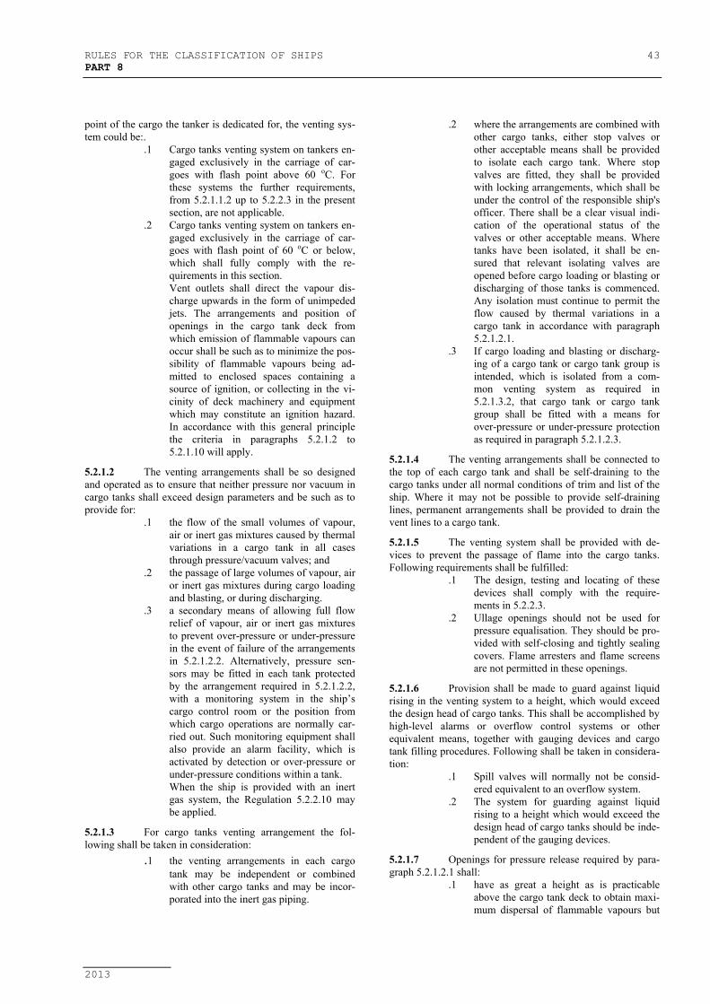
RULES FOR THE CLASSIFICATION OF SHIPS 43PART 8
2013
point of the cargo the tanker is dedicated for, the venting sys-tem could be:.
.1 Cargo tanks venting system on tankers en-gaged exclusively in the carriage of car-goes with flash point above 60 oC. Forthese systems the further requirements,from 5.2.1.1.2 up to 5.2.2.3 in the presentsection, are not applicable.
.2 Cargo tanks venting system on tankers en-gaged exclusively in the carriage of car-goes with flash point of 60 oC or below,which shall fully comply with the re-quirements in this section.Vent outlets shall direct the vapour dis-charge upwards in the form of unimpededjets. The arrangements and position ofopenings in the cargo tank deck fromwhich emission of flammable vapours canoccur shall be such as to minimize the pos-sibility of flammable vapours being ad-mitted to enclosed spaces containing asource of ignition, or collecting in the vi-cinity of deck machinery and equipmentwhich may constitute an ignition hazard.In accordance with this general principlethe criteria in paragraphs 5.2.1.2 to5.2.1.10 will apply.
5.2.1.2 The venting arrangements shall be so designedand operated as to ensure that neither pressure nor vacuum incargo tanks shall exceed design parameters and be such as toprovide for:
.1 the flow of the small volumes of vapour,air or inert gas mixtures caused by thermalvariations in a cargo tank in all casesthrough pressure/vacuum valves; and
.2 the passage of large volumes of vapour, airor inert gas mixtures during cargo loadingand blasting, or during discharging.
.3 a secondary means of allowing full flowrelief of vapour, air or inert gas mixturesto prevent over-pressure or under-pressurein the event of failure of the arrangementsin 5.2.1.2.2. Alternatively, pressure sen-sors may be fitted in each tank protectedby the arrangement required in 5.2.1.2.2,with a monitoring system in the ship’scargo control room or the position fromwhich cargo operations are normally car-ried out. Such monitoring equipment shallalso provide an alarm facility, which isactivated by detection or over-pressure orunder-pressure conditions within a tank.When the ship is provided with an inertgas system, the Regulation 5.2.2.10 maybe applied.
5.2.1.3 For cargo tanks venting arrangement the fol-lowing shall be taken in consideration:
.1 the venting arrangements in each cargotank may be independent or combinedwith other cargo tanks and may be incor-porated into the inert gas piping.
.2 where the arrangements are combined withother cargo tanks, either stop valves orother acceptable means shall be providedto isolate each cargo tank. Where stopvalves are fitted, they shall be providedwith locking arrangements, which shall beunder the control of the responsible ship'sofficer. There shall be a clear visual indi-cation of the operational status of thevalves or other acceptable means. Wheretanks have been isolated, it shall be en-sured that relevant isolating valves areopened before cargo loading or blasting ordischarging of those tanks is commenced.Any isolation must continue to permit theflow caused by thermal variations in acargo tank in accordance with paragraph5.2.1.2.1.
.3 If cargo loading and blasting or discharg-ing of a cargo tank or cargo tank group isintended, which is isolated from a com-mon venting system as required in5.2.1.3.2, that cargo tank or cargo tankgroup shall be fitted with a means forover-pressure or under-pressure protectionas required in paragraph 5.2.1.2.3.
5.2.1.4 The venting arrangements shall be connected tothe top of each cargo tank and shall be self-draining to thecargo tanks under all normal conditions of trim and list of theship. Where it may not be possible to provide self-draininglines, permanent arrangements shall be provided to drain thevent lines to a cargo tank.
5.2.1.5 The venting system shall be provided with de-vices to prevent the passage of flame into the cargo tanks.Following requirements shall be fulfilled:
.1 The design, testing and locating of thesedevices shall comply with the require-ments in 5.2.2.3.
.2 Ullage openings should not be used forpressure equalisation. They should be pro-vided with self-closing and tightly sealingcovers. Flame arresters and flame screensare not permitted in these openings.
5.2.1.6 Provision shall be made to guard against liquidrising in the venting system to a height, which would exceedthe design head of cargo tanks. This shall be accomplished byhigh-level alarms or overflow control systems or otherequivalent means, together with gauging devices and cargotank filling procedures. Following shall be taken in considera-tion:
.1 Spill valves will normally not be consid-ered equivalent to an overflow system.
.2 The system for guarding against liquidrising to a height which would exceed thedesign head of cargo tanks should be inde-pendent of the gauging devices.
5.2.1.7 Openings for pressure release required by para-graph 5.2.1.2.1 shall:
.1 have as great a height as is practicableabove the cargo tank deck to obtain maxi-mum dispersal of flammable vapours but
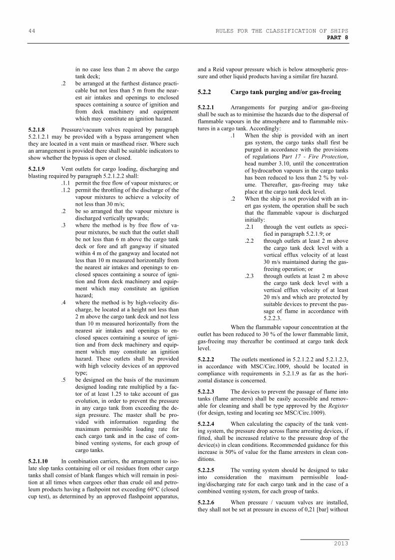
44 RULES FOR THE CLASSIFICATION OF SHIPSPART 8
2013
in no case less than 2 m above the cargotank deck;
.2 be arranged at the furthest distance practi-cable but not less than 5 m from the near-est air intakes and openings to enclosedspaces containing a source of ignition andfrom deck machinery and equipmentwhich may constitute an ignition hazard.
5.2.1.8 Pressure/vacuum valves required by paragraph5.2.1.2.1 may be provided with a bypass arrangement whenthey are located in a vent main or masthead riser. Where suchan arrangement is provided there shall be suitable indicators toshow whether the bypass is open or closed.
5.2.1.9 Vent outlets for cargo loading, discharging andblasting required by paragraph 5.2.1.2.2 shall:
.1.1 permit the free flow of vapour mixtures; or
.1.2 permit the throttling of the discharge of thevapour mixtures to achieve a velocity ofnot less than 30 m/s;
.2 be so arranged that the vapour mixture isdischarged vertically upwards;
.3 where the method is by free flow of va-pour mixtures, be such that the outlet shallbe not less than 6 m above the cargo tankdeck or fore and aft gangway if situatedwithin 4 m of the gangway and located notless than 10 m measured horizontally fromthe nearest air intakes and openings to en-closed spaces containing a source of igni-tion and from deck machinery and equip-ment which may constitute an ignitionhazard;
.4 where the method is by high-velocity dis-charge, be located at a height not less than2 m above the cargo tank deck and not lessthan 10 m measured horizontally from thenearest air intakes and openings to en-closed spaces containing a source of igni-tion and from deck machinery and equip-ment which may constitute an ignitionhazard. These outlets shall be providedwith high velocity devices of an approvedtype;
.5 be designed on the basis of the maximumdesigned loading rate multiplied by a fac-tor of at least 1.25 to take account of gasevolution, in order to prevent the pressurein any cargo tank from exceeding the de-sign pressure. The master shall be pro-vided with information regarding themaximum permissible loading rate foreach cargo tank and in the case of com-bined venting systems, for each group ofcargo tanks.
5.2.1.10 In combination carriers, the arrangement to iso-late slop tanks containing oil or oil residues from other cargotanks shall consist of blank flanges which will remain in posi-tion at all times when cargoes other than crude oil and petro-leum products having a flashpoint not exceeding 60°C (closedcup test), as determined by an approved flashpoint apparatus,
and a Reid vapour pressure which is below atmospheric pres-sure and other liquid products having a similar fire hazard.
5.2.2 Cargo tank purging and/or gas-freeing
5.2.2.1 Arrangements for purging and/or gas-freeingshall be such as to minimise the hazards due to the dispersal offlammable vapours in the atmosphere and to flammable mix-tures in a cargo tank. Accordingly:
.1 When the ship is provided with an inertgas system, the cargo tanks shall first bepurged in accordance with the provisionsof regulations Part 17 - Fire Protection,head number 3.10, until the concentrationof hydrocarbon vapours in the cargo tankshas been reduced to less than 2 % by vol-ume. Thereafter, gas-freeing may takeplace at the cargo tank deck level.
.2 When the ship is not provided with an in-ert gas system, the operation shall be suchthat the flammable vapour is dischargedinitially:.2.1 through the vent outlets as speci-
fied in paragraph 5.2.1.9; or.2.2 through outlets at least 2 m above
the cargo tank deck level with avertical efflux velocity of at least30 m/s maintained during the gas-freeing operation; or
.2.3 through outlets at least 2 m abovethe cargo tank deck level with avertical efflux velocity of at least20 m/s and which are protected bysuitable devices to prevent the pas-sage of flame in accordance with5.2.2.3.
When the flammable vapour concentration at theoutlet has been reduced to 30 % of the lower flammable limit,gas-freeing may thereafter be continued at cargo tank decklevel.
5.2.2.2 The outlets mentioned in 5.2.1.2.2 and 5.2.1.2.3,in accordance with MSC/Circ.1009, should be located incompliance with requirements in 5.2.1.9 as far as the hori-zontal distance is concerned.
5.2.2.3 The devices to prevent the passage of flame intotanks (flame arresters) shall be easily accessible and remov-able for cleaning and shall be type approved by the Register(for design, testing and locating see MSC/Circ.1009).
5.2.2.4 When calculating the capacity of the tank vent-ing system, the pressure drop across flame arresting devices, iffitted, shall be increased relative to the pressure drop of thedevice(s) in clean conditions. Recommended guidance for thisincrease is 50% of value for the flame arresters in clean con-ditions.
5.2.2.5 The venting system should be designed to takeinto consideration the maximum permissible load-ing/discharging rate for each cargo tank and in the case of acombined venting system, for each group of tanks.
5.2.2.6 When pressure / vacuum valves are installed,they shall not be set at pressure in excess of 0,21 [bar] without

RULES FOR THE CLASSIFICATION OF SHIPS 45PART 8
2013
a special permissions of Register, based upon the considera-tion of tank scantling and cargo category.
5.2.2.7 Slop tanks are to be equipped with the sameventing arrangements as cargo tanks.
5.2.2.8 For ships below 500 GT, which are not engagedon international voyages, unless expressly provided otherwise,the application of this requirement is subject to special con-sideration by the Register in each particular case.
5.2.9 Cargo tanks venting and gas-freeing arrange-ment on chemical tankers shall comply with requirements inPart 27 -Chemical Tankers, head number 6.4.
5.2.10 Inert gas system, if installed, shall comply withrequirements in Part 17 - Fire Protection, head number 3.10.
A P/V breaker fitted on the inert gas main maybe utilised as the required secondary means of venting re-quired in 5.2.1.2.3. The height requirements in 5.2.1.7 and5.2.1.9 and the requirements for devices to prevent the pas-sages of flame of Regulation 5.2.1.5 are not applicable to theP/V breaker provided the settings are above those of theventing arrangements required by Regulation 5.2.1.2.1 and5.2.1.2.2.
Where the venting arrangements are of the freeflow type and the masthead isolating valve is closed for theunloading condition, the inert gas systems will serve as theprimary underpressure protection with the P/V breaker servingas the secondary means.
5.2.11 Electrical equipment fitted in compliance withIEC 92-502 is not considered to be a source of ignition or ig-nition hazard.
5.3 OVERFLOW PIPES
5.3.1 As a rule, each tank is to be fitted with overflowpipes. Fuel oil tanks shall be provided with overflow pipesleading to the overflow tank or settling tank having increasedcapacity, but in no case their capacity shall be less than that ofthe overflow tank specified in 5.4.1 and equipped in compli-ance with 5.4.2. The use of a fuel storage tank as overflowtank is permissible but requires the installation of a high levelalarm and an air pipe with 1,25 times the cross-sectional areaof the main bunkering line.
The overflow pipes may be omitted if the ar-rangement of the fuel or lubricating oil system is such that thepossibility of spilling overboard during loading and transfer-ring of fuel or lubricating oil is precluded.
5.3.2 Cross-sectional area of the overflow pipes shallbe the same as for the air pipes (5.1.10 to 5.1.13). Cross- sec-tional area of slop tank overflow pipes shall be at least 2 timesgreater than sectional area of filling pipes.
5.3.3 Where the overflow pipes from several tanks,situated in different watertight compartments, are led to acommon header or pipe, this header or pipe shall be situatedabove the deepest damage waterline in ships which are tocomply with the requirements for subdivision in damagedcondition, and above the deepest load waterline in other ships.
The overflow collecting manifolds of fuel tanksare to be led at a sufficient gradient to an overflow tank. Over-
flow systems of heavy oil tanks shall be specially designed toavoid solidification of the liquid in the pipes, with insulatedand heated overflow pipes where necessary.
5.3.4 Where the air pipes are simultaneously used asoverflow pipes, they shall not be connected to the air pipe ofan overflow tank. In this case, the overflow pipes, or a com-mon overflow pipe shall be connected directly to the overflowtank.
5.3.5 Where the tank is used alternately for the car-riage of fuel oil, water ballast, liquid cargoes or dry cargo,overflow pipes shall be so arranged as to preclude the possi-bility of liquid flowing from one tank into another and liquidcargo vapours entering a tank with dry cargo. In such cases,subject to agreement with the Register, the overflow pipesmay be fitted with shut-off valves, provided these pipes arenot used as air pipes.
5.3.6 Overflow pipes of the daily tanks and fuel oiland lubricating oil settling tanks, shall be led into overflowtanks located lower than the above stated tanks.
5.3.7 Overflow pipes shall be provided with a sightglass, fitted at a readily visible and accessible place, on verti-cal part of pipe or with an alarm device to give warningwhether the fuel is over-flowing (See 5.4.2).
5.3.8 Overflow pipes passing through cargo holds areto be protected against damage.
5.4 OVERFLOW TANKS
5.4.1 The capacity of an overflow tank shall be notless than 10 minute capacity of the fuel transfer pump.
5.4.2 An overflow tank shall be provided with audibleand visual alarms operating whenever the tank filling exceeds75 per cent.
5.5 SOUNDING ARRANGEMENTS
5.5.1 Each tank, cofferdams and void spaces withbilge connections, as well as bilge and bilge wells in spaceswhich are not accessible at all times, shall be fitted withsounding pipes carried, as a rule, to the open deck. As far aspossible, sounding pipes are to be laid straight and are to ex-tend as near as possible to the bottom.
On application, the provision of sounding pipesfor bilge wells in permanently accessible spaces may be dis-pensed with.
Where the tanks are fitted with remote level in-dicators, which are type-approved, the arrangement of sound-ing pipes can be dispensed with.
Sounding pipe outlets of fuel oil and lubricatingoil tanks shall not be led neither in accommodation nor offi-cial rooms where oil from these pipes may present the risk offire.
As a rule, sounding pipe outlets shall not termi-nate in machinery spaces. However, where this requirement isimpracticable, the Register may permit exception if the fol-lowing requirements are met:
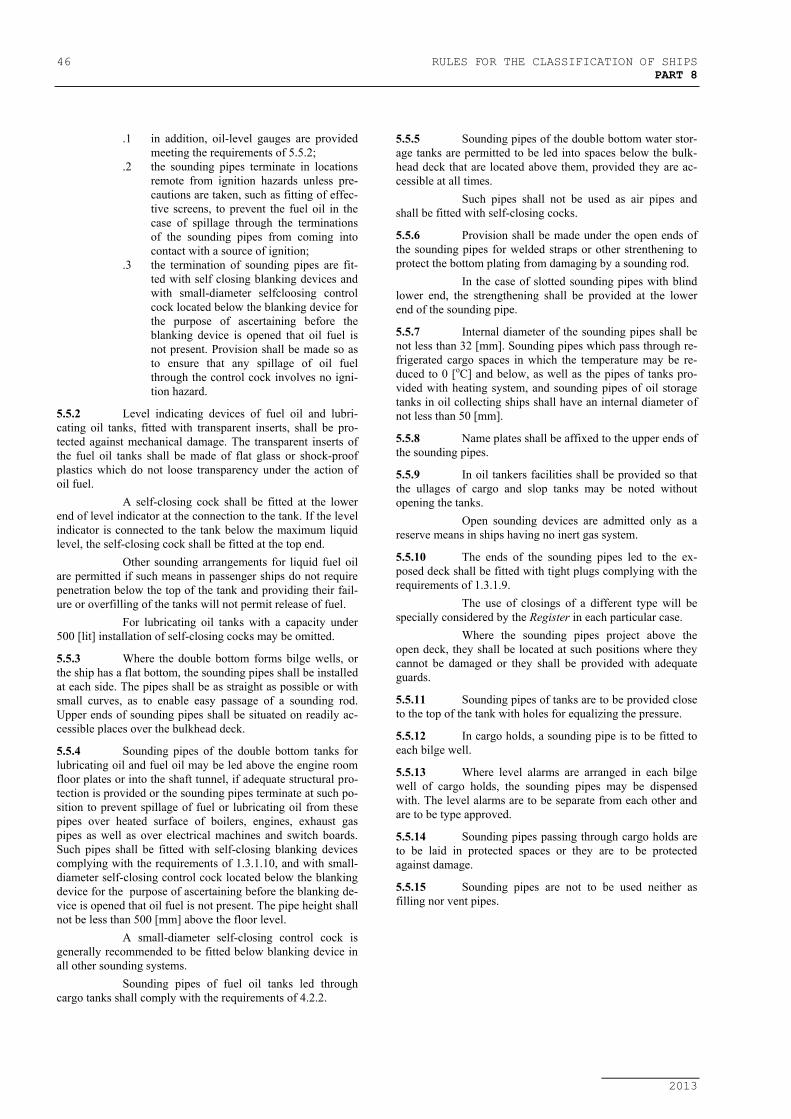
46 RULES FOR THE CLASSIFICATION OF SHIPSPART 8
2013
.1 in addition, oil-level gauges are providedmeeting the requirements of 5.5.2;
.2 the sounding pipes terminate in locationsremote from ignition hazards unless pre-cautions are taken, such as fitting of effec-tive screens, to prevent the fuel oil in thecase of spillage through the terminationsof the sounding pipes from coming intocontact with a source of ignition;
.3 the termination of sounding pipes are fit-ted with self closing blanking devices andwith small-diameter selfcloosing controlcock located below the blanking device forthe purpose of ascertaining before theblanking device is opened that oil fuel isnot present. Provision shall be made so asto ensure that any spillage of oil fuelthrough the control cock involves no igni-tion hazard.
5.5.2 Level indicating devices of fuel oil and lubri-cating oil tanks, fitted with transparent inserts, shall be pro-tected against mechanical damage. The transparent inserts ofthe fuel oil tanks shall be made of flat glass or shock-proofplastics which do not loose transparency under the action ofoil fuel.
A self-closing cock shall be fitted at the lowerend of level indicator at the connection to the tank. If the levelindicator is connected to the tank below the maximum liquidlevel, the self-closing cock shall be fitted at the top end.
Other sounding arrangements for liquid fuel oilare permitted if such means in passenger ships do not requirepenetration below the top of the tank and providing their fail-ure or overfilling of the tanks will not permit release of fuel.
For lubricating oil tanks with a capacity under500 [lit] installation of self-closing cocks may be omitted.
5.5.3 Where the double bottom forms bilge wells, orthe ship has a flat bottom, the sounding pipes shall be installedat each side. The pipes shall be as straight as possible or withsmall curves, as to enable easy passage of a sounding rod.Upper ends of sounding pipes shall be situated on readily ac-cessible places over the bulkhead deck.
5.5.4 Sounding pipes of the double bottom tanks forlubricating oil and fuel oil may be led above the engine roomfloor plates or into the shaft tunnel, if adequate structural pro-tection is provided or the sounding pipes terminate at such po-sition to prevent spillage of fuel or lubricating oil from thesepipes over heated surface of boilers, engines, exhaust gaspipes as well as over electrical machines and switch boards.Such pipes shall be fitted with self-closing blanking devicescomplying with the requirements of 1.3.1.10, and with small-diameter self-closing control cock located below the blankingdevice for the purpose of ascertaining before the blanking de-vice is opened that oil fuel is not present. The pipe height shallnot be less than 500 [mm] above the floor level.
A small-diameter self-closing control cock isgenerally recommended to be fitted below blanking device inall other sounding systems.
Sounding pipes of fuel oil tanks led throughcargo tanks shall comply with the requirements of 4.2.2.
5.5.5 Sounding pipes of the double bottom water stor-age tanks are permitted to be led into spaces below the bulk-head deck that are located above them, provided they are ac-cessible at all times.
Such pipes shall not be used as air pipes andshall be fitted with self-closing cocks.
5.5.6 Provision shall be made under the open ends ofthe sounding pipes for welded straps or other strenthening toprotect the bottom plating from damaging by a sounding rod.
In the case of slotted sounding pipes with blindlower end, the strengthening shall be provided at the lowerend of the sounding pipe.
5.5.7 Internal diameter of the sounding pipes shall benot less than 32 [mm]. Sounding pipes which pass through re-frigerated cargo spaces in which the temperature may be re-duced to 0 [oC] and below, as well as the pipes of tanks pro-vided with heating system, and sounding pipes of oil storagetanks in oil collecting ships shall have an internal diameter ofnot less than 50 [mm].
5.5.8 Name plates shall be affixed to the upper ends ofthe sounding pipes.
5.5.9 In oil tankers facilities shall be provided so thatthe ullages of cargo and slop tanks may be noted withoutopening the tanks.
Open sounding devices are admitted only as areserve means in ships having no inert gas system.
5.5.10 The ends of the sounding pipes led to the ex-posed deck shall be fitted with tight plugs complying with therequirements of 1.3.1.9.
The use of closings of a different type will bespecially considered by the Register in each particular case.
Where the sounding pipes project above theopen deck, they shall be located at such positions where theycannot be damaged or they shall be provided with adequateguards.
5.5.11 Sounding pipes of tanks are to be provided closeto the top of the tank with holes for equalizing the pressure.
5.5.12 In cargo holds, a sounding pipe is to be fitted toeach bilge well.
5.5.13 Where level alarms are arranged in each bilgewell of cargo holds, the sounding pipes may be dispensedwith. The level alarms are to be separate from each other andare to be type approved.
5.5.14 Sounding pipes passing through cargo holds areto be laid in protected spaces or they are to be protectedagainst damage.
5.5.15 Sounding pipes are not to be used neither asfilling nor vent pipes.

RULES FOR THE CLASSIFICATION OF SHIPS 47PART 8
2013
6 EXHAUST GAS SYSTEM
6.1 EXHAUST GAS PIPES
6.1.1 The exhaust gas pipes, as a rule, shall be led tothe open decks.
6.1.2 Where the exhaust gas pipes are led through theshell plating in the vicinity of load waterline or below it, pro-vision shall be made for arrangements precluding the possi-bility of sea water getting into the engine.
6.1.3 In oil tankers, timber carriers, supply vessels andoil collecting ships, ships for carriage of dangerous cargoesand in ships taking the above mentioned ships in tow, the up-takes of boilers and galleys as well as the exhaust gas pipes ofthe propulsion and auxiliary engines shall be fitted with sparkarresters of a construction approved by the Register.In above mentioned ships, the exhaust gas pipes may be ledthrough the shell plating at a distance not less than 0,3 [m]below the waterline of a ship in light condition.
6.1.4 The exhaust gas pipes shall be led at a distancenot less than 450 [mm] from the fuel oil tanks.
6.1.5 Each propulsion engine shall have an individualexhaust gas pipe. Where required, exceptions may be allowed,subject to special consideration by the Register.
Exhaust gas pipes of auxiliary engines may beconnected to a common exhaust gas pipeline only if provisionis made for a reliable protective device that will preclude:
− the gases of the common line entering thepipes of the engines not actually at work;
− damage of any of the engines when starting.In ships of restricted areas of navigation 5 to 8,
the exhaust gas pipes of the propulsion and auxiliary enginesmay be permitted to connect to a common exhaust line, pro-vided the foregoing precautions are fulfilled.
6.1.6 Exhaust gas boilers and composite boilers,which by reason of structural features cannot be left withoutwater while heated by exhaust gases, shall be provided withbypass lines and dampers.
6.1.7 Uptakes of boilers and exhaust gas pipes of in-ternal combustion engines shall be thermally insulated bymeans of suitable insulating material, with double walls or ascreen.
Where the thermal insulation is provided, insu-lating materials shall comply with requirements of the Rules,Part 7 - Machinery Installations, 1.11.9.
Double walls or a screen are permitted to beused only at places where, in case of overflow, pouring of fuelon them is precluded.
6.1.8 When the uptakes of main and auxiliary boilersare arranged to discharge into a common uptake, dampers arepermitted to be used in the uptake, provided they have ar-rangements to be locked open. When required, manholes andvertical ladders shall be provided for inspection and cleaningof the uptakes and air ducts of boilers.
6.1.9 In tankers exhaust gas pipes of main and auxil-iary engines, boilers, galleys and other installations with igni-tion sources as well as ventilation pipes of crankcase of inter-nal combustion engines, shall be fitted at least 6 [m] above thehighest water line and out of hazardous zones specified in theRules, Part 12 - Electric Equipment.
6.1.10 Exhaust gas piping of diesel generators with re-mote and automatic control shall be provided with drain de-vices capable to prevent the entry of water into engine.
Drain devices shall be fitted on easy accessibleplaces and shall be provided with a possibility of cleaning.
Internal diameter of drain pipe of such devicesshall not be less than 25 [mm].
6.1.11 Materials, manufacture and application of ex-haust gas pipes shall be in lieu with 1.3.1.2, 1.3.7.1 and1.3.7.2, and tables 1.2.2, 1.3.4.3 and 1.3.7.7.
6.2 SILENCERS AND SPARKARRESTERS
6.2.1 Silencers and spark arresters shall be so ar-ranged as to permit cleaning. For this purpose they shall befitted with appropriate handholes and drain cocks.
6.2.2 Where waste-gas boilers and spark arresters ofthe wet type are installed, measures shall be taken to preventthe entry of water into the engines. For this purpose the drainpipes shall be led into the bilges of the engine room and shallbe provided with hydraulic seals.

48 RULES FOR THE CLASSIFICATION OF SHIPSPART 8
2013
7 VENTILATION SYSTEM
7.1 VENTILATION DUCTS
7.1.1 Ventilation ducts shall not be led through water-tight bulkheads below the bulkhead deck.
7.1.2 Where trunkways and vertical ducts of the ven-tilation system pass through watertight decks, they shall bewatertight and equivalent in strength to adjacent hull struc-tures within a single watertight compartment below the bulk-head deck.
7.1.3 Ventilation ducts shall be adequately protectedagainst corrosion or costructed of corrosion-resistant materi-als.
7.1.4 Ventilation ducts for removal of explosion andfire-dangerous vapours and gases shall be gastight and shallnot communicate with the ducts of other spaces. In general,particular attention shall be drawn to the following:
.1 The non-combustible material shall beused in accordance with the SOLAS II-2/9.7.1.1.However, the flexible bellows of combus-tible material may be used for connectingfans to the ducting in air conditioningroom.
.2 Testing required in SOLAS II-2/9.7.1.2shall be included.
.3 Arrangement of ventilation ducts shallcomply with the SOLAS II-2/9.7.2.
.4 Details of duct penetrations are to complywith the SOLAS II-2/9.7.3.
.5 Ducts or pipes with free sectional area of750 [cm2] or less need not be fitted withfire damper at their passage through Class"A" divisions (required in SOLAS II-2/9.7.3.1) provided that the requirementsof SOLAS II-2/9.7.2.1, 9.7.2.2, 9.4.1.1.8,9.3.3 and 9.7.4.3 are complied with.
7.1.5 Ventilation ducts leading to cargo spaces, ma-chinery spaces and other spaces fitted with smothering facili-ties are to have closing arrangements complying with theRules, Part 17 - Fire Protection, 2.1.4.2.
Closing arrangements shall be provided withmeans for closing them from positions outside these spaces.
7.1.6 In places of possible sweating the ventilationducts are to be properly insulated. Drain plugs shall be pro-vided for the portions of ducts where water is likely to accu-mulate.
7.1.7 Ventilator heads of supply ducts and the air in-lets of ventilation systems shall be so located that the risk ofdrawing in of air contaminated by gas, oil vapours, etc., isminimized, and admission of sea water into the ventilationducts is precluded.
7.1.8 Ventilator coamings shall have a height in ac-cordance with the Rules, Part 3 - Hull Equipment, 7.8.
7.2 VENTILATION OF CARGO SHIPSOF 500 TONS GROSS TONNAGE AND
UPWARDS, PASSENGER SHIPSCARRYING NOT MORE THAN 36
PASSENGERS AND SPECIAL PURPOSESHIPS CARRYING NOT MORE THAN
200 PERSONS IN ADDITION TO CREWMEMBERS
7.2.1 Ventilation systems of accommodation spaces,service spaces and control stations shall comply with require-ments of this Chapter.
7.2.2 Ventilation ducts shall be constructed of non-combustible materials. However, ducts with a cross-sectionalarea not exceeding 200 [cm2] and a length not over 2 [m] maybe constructed of combustible material having low flamespread characteristics (see the Rules, Part 17 - Fire Protec-tion, 1.5.3), if the following conditions are met:
.1 the duct is used only at the end section ofthe ventilation system;
.2 the duct is at a distance of at least 60 [cm],measured along the duct, from the pene-tration of an A or B class division, in-cluding continuous B class deck.
7.2.3 Where the ventilation ducts with a cross-sectional area exceeding 200 [cm2] pass through A classdecks, openings shall be lined with a steel sheet sleeve unlessthe ducts passing through bulkheads or decks are of steel inway of passage through the deck or bulkhead. The ducts andsleeves in this area shall comply with the following condi-tions:
.1 The sleeves shall have a thickness of atleast 3 [mm] and a length of 900 [mm].When passing through the bulkhead, thislength shall be divided into 450 [mm] oneach side of the bulkhead.The ducts and the sleeves shall be pro-vided with fire insulation having fire in-tegrity not less than the bulkhead or deckthrough which the duct passes. Equivalentpenetration may be admitted in agreementwith the Register.
.2 Ducts with a cross-sectional area exceed-ing 750 [cm2] shall be fitted with firedampers in addition to the requirements of7.2.3.1. The fire damper shall be operatedautomatically, and shall be also capable ofbeing operated manually from both sidesof the bulkhead or deck. The damper shallbe provided with an indicator showingwhether the damper is in position “open”or “closed”. Fire dampers are not required,where the ducts pass through spaces sur-rounded by A class divisions, withoutserving those spaces, provided the ductshave the same fire integrity as the bulk-heads which they pierce.
7.2.4 Ducts provided for the ventilation of machineryspaces of category A, galleys, cargo spaces of ro-ro ships, car

RULES FOR THE CLASSIFICATION OF SHIPS 49PART 8
2013
deck spaces or special category spaces, shall not pass throughaccommodation spaces, service spaces or control stations, ex-cept where:
.1 the ducts are constructed of steel having athickness of at least 3 and 5 [mm] forducts the width or diameter of which areup to and including 300 and 760 [mm] andover, respectively. For ducts, the width ordiameter of which are between 300 and760 [mm], the thickness shall be deter-mined by interpolation;
.2 the ducts are suitably supported and stiff-ened;
.3 the ducts are fitted with automatic firedampers close to the boundaries pene-trated, and are insulated to A-60 standardto a point at least 5 [m] beyond each firedamper, or;
.4 the ducts are constructed of steel in accor-dance with requirements of .1 and .2, andare insulated to A-60 standard throughoutthe accommodation spaces, service spacesor control stations.
If the ventilation duct is led through the mainvertical zone divisions, the requirements of 7.2.8 shall be alsocomplied with.
The above-stated requirements shall apply alsoto the ducts, intended for ventilation of accommodationspaces, service spaces or control stations, which pass throughmachinery spaces of category A, galleys, cargo spaces of ro-roships, car deck spaces or special category spaces, unless theycomply with the requirements of 7.2.4.1 - 7.2.4.3 or 7.2.4.4.
7.2.5 Where ventilation ducts with a cross-sectionalarea exceeding 200 [cm2] pass through B class bulkheads, theopenings shall be lined with steel sheet sleeves of 900 [mm] inlength, unless the ducts are of steel for this length in way ofthe bulkhead. This length shall be divided simetrically to thebulkhead.
7.2.6 All necessary measures shall be taken for per-manent ventilation of the control stations outside the machin-ery spaces, to ensure visibility and absence of smoke.
For ventilation of these control stations two al-ternative and separate means of air supply shall be providedwith the inlets of ducts so arranged that the risk of both inletsdrawing in smoke simultaneously is minimized.
These requirements may not be applied to thecontrol stations situated on the open deck, to which they havea direct exit or where there are equally effective local closuresof the control stations.
7.2.7 Galley ventilation systems shall be separatedfrom the ventilation systems serving other spaces.
Exhaust ducts from galley shall be constructedas A class divisions where they pass through accommodationspaces or spaces containing combustible materials. Each ex-haust duct shall be fitted with a readily removable grease trap,a fire damper located in the lower end of the duct, remotecontrol arrangements for shutting off the exhaust fans, con-trolled from the galley and fixed means for extinguishing afire within the duct.
7.2.8 Where in passenger ships it is necessary that aventilation duct passes through a main vertical zone division,a failsafe automatic closing fire damper shall be fitted adja-cent to the division. The damper shall be also capable of beingmanually closed from each side of the division. The positionfor operating the damper shall be readily accessible and bemarked in red light-reflecting colour. The duct between thedivision and damper shall be made of steel or other equivalentmaterial and, where necessary, shall be provided with insula-tion corresponding to the degree of fire integrity of the divi-sion. At least at one side of the division the damper shall befitted with a readily visible indicator showing whether thedamper is open or closed.
7.2.9 Provision shall be made for closing the main in-lets and outlets of all ventilation systems from outside theventilated spaces.
7.2.10 Ventilation ducts and their passages through Aor B class divisions in ships of less than 500 tons gross ton-nage shall, generally, be constructed in compliance with therequirements of this Chapter.
The deviations from these requirements aresubject to special consideration by the Register.
7.3 VENTILATION OF PASSENGERSHIPS CARRYING MORE THAN 36
PASSENGERS AND SPECIAL PURPOSESHIPS CARRYING MORE THAN 200PERSONS IN ADDITION TO CREW
MEMBERS
7.3.1 Ventilation systems of accommodation spaces,service spaces and control stations shall comply with the re-quirements of 7.2.
7.3.2 In general, ventilation fans and ducts shall be in-stalled within the main vertical fire zone which they serve.
7.3.3 Where the ventilation ducts are led through thedecks, measures shall be taken to minimize the possibility ofsmoke and flammable gases passing from one tween-deckspace to another. If necessary, vertical ducts shall be insulatedas required by the Rules, Part 17 - Fire Protection, 2.2.4.1.
7.3.4 Except in cargo spaces, ventilation ducts shall beconstructed of the following materials:
.1 Ducts with a cross-sectional area morethan 750 [cm2] and all vertical ducts serv-ing more than a single tween-deck spaceshall be constructed of steel or otherequivalent material.
.2 Ducts with a cross-sectional area less than750 [cm2] other than the vertical ductsmentioned in .1 shall be constructed ofnon-combustible materials. Where suchducts penetrate A or B class divisions, dueregard shall be given to ensuring the fireintegrity of the divisions.
.3 for ducts not exceeding 200 [cm2] in sec-tional area nor 2 [m] in length, see 7.2.2.
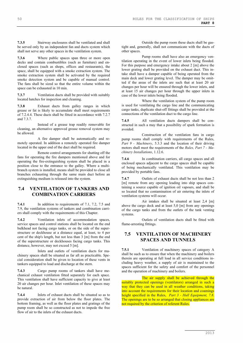
50 RULES FOR THE CLASSIFICATION OF SHIPSPART 8
2013
7.3.5 Stairway enclosures shall be ventilated and shallbe served only by an independent fan and ducts system whichshall not serve any other spaces in the ventilation system.
7.3.6 Where public spaces span three or more opendecks and contain combustibles (such as furniture) and en-closed spaces (such as shops, offices and restaurants), thespace, shall be equipped with a smoke extraction system. Thesmoke extraction system shall be activated by the requiredsmoke detection system and be capable of manual control.The fans shall be sized so that the entire volume within thespace can be exhausted in 10 min.
7.3.7 Ventilation ducts shall be provided with suitablylocated hatches for inspection and cleaning.
7.3.8 Exhaust ducts from galley ranges in whichgrease or fat is likely to accumulate shall meet requirementsof 7.2.4.4. These ducts shall be fitted in accordance with 7.2.7and 7.3.7.
Instead of a grease trap readily removable forcleaning, an alternative approved grease removal system maybe allowed.
A fire damper shall be automatically and re-motely operated. In addition a remotely operated fire damperlocated in the upper end of the duct shall be required.
Remote control arrangements for shutting off thefans for operating the fire dampers mentioned above and foroperating the fire-extinguishing system shall be placed in aposition close to the entrance to the galley. Where a multi-branch system is installed, means shall be provided to close allbranches exhausting through the same main duct before anextinguishing medium is released into the system.
7.4 VENTILATION OF TANKERS ANDCOMBINATION CARRIERS
7.4.1 In addition to requirements of 7.1, 7.2, 7.5 and7.9, the ventilation systems of tankers and combination carri-ers shall comply with the requirements of this Chapter.
7.4.2 Ventilation inlets of accommodation spaces,service spaces and control stations shall be located on the endbulkhead not facing cargo tanks, or on the side of the super-structure or deckhouse at a distance equal, at least, to 4 percent of the ship's length, but not less than 3 [m] from the endof the superstructure or deckhouses facing cargo tanks. Thisdistance, however, may not exceed 5 [m].
Inlets and outlets of ventilation ducts for ma-chinery spaces shall be situated as far aft as practicable. Spe-cial consideration shall be given to location of these vents intankers equipped to load and discharge at the stern.
7.4.3 Cargo pump rooms of tankers shall have me-chanical exhaust ventilation fitted separately for each space.This ventilation shall have sufficient capacity to give at least20 air changes per hour. Inlet ventilation of these spaces maybe natural.
7.4.4 Inlets of exhaust ducts shall be situated so as toprovide extraction of air from below the floor plates. Thebottom framing, as well as the floor plates and gratings of thepump room shall be so constructed as not to impede the freeflow of air to the inlets of the exhaust ducts.
Outside the pump room these ducts shall be gas-tight and, generally, shall not communicate with the ducts ofother spaces.
Pump rooms shall have also an emergency ven-tilation operating in the event of lower inlets being flooded.For this purpose and emergency intake about 2 [m] above thelower grating shall be provided on the exhaust duct. This in-take shall have a damper capable of being operated from themain deck and lower grating level. The damper may be omit-ted if the areas of the inlets are such that at least 20 airchanges per hour will be ensured through the lower inlets, andat least 15 air changes per hour through the upper inlets incase of the lower inlets being flooded.
Where the ventilation system of the pump roomis used for ventilating the cargo line and the communicatingcargo tanks, duplicate shut-off fittings shall be provided at theconnections of the ventilation duct to the cargo line.
7.4.5 All ventilation ducts dampers shall be con-structed in such a may that a possibility of spark formation isavoided.
Construction of the ventilation fans in cargopump rooms shall comply with requirements of the Rules,Part 9 - Machinery, 5.3.3 and the location of their drivingmotors shall meet the requirements of the Rules, Part 7 - Ma-chinery Installations, 1.12.6.
7.4.6 In combination carriers, all cargo spaces and allenclosed spaces adjacent to the cargo spaces shall be capableof being mechanically ventilated. This ventilation may beprovided by portable fans.
7.4.7 Outlets of exhaust ducts shall be not less than 2[m] remote from any opening leading into ship spaces con-taining a source capable of ignition oil vapours, and shall beso located that no contamination of air entering the inlets ofventilation systems will occur.
Air intakes shall be situated at least 2,4 [m]above the cargo deck and at least 5,0 [m] from any openingsof the cargo tanks and from the outlets of the tank ventingsystems.
Outlets of ventilation ducts shall be fitted withflame-arresting fittings.
7.5 VENTILATION OF MACHINERYSPACES AND TUNNELS
7.5.1 Ventilation of machinery spaces of category Ashall be such as to ensure that when the machinery and boilerstherein are operating at full load in all service conditions in-cluding heavy weather, a supply of air is maintained to thespaces sufficient for the safety and comfort of the personneland the operation of machinery and boilers.
The air supply shall be achieved through thesuitably protected openings (ventilators) arranged in such away that they can be used in all weather conditions, takinginto account the requirements for their location and coamingsheight specified in the Rules, Part 3 - Hull Equipment, 7.8.The openings are to be so arranged that closing appliances arenot required by the criterion of referent Rules.

RULES FOR THE CLASSIFICATION OF SHIPS 51PART 8
2013
Ventilation shall prevent formation of trappedzones also below the floor plates and near the oil fuel tanksand equipments.
Any other machinery spaces shall be adequatelyventilated appropriate to the purpose of the machinery space.
For the ventilation of spaces containing refriger-ating machinery, see the Rules, Part - 11 Refrigerating Plants,3.1.8 and 3.1.9.
7.5.2 Shaft tunnels shall be properly ventilated. Pipetunnels led in the double bottom shall have mechanical ex-haust ventilation.
7.5.3 Space containing emergency diesel-generatorshall be provided with appropriate means to ensure an air sup-ply suifficient for the emergency diesel-generator to continuerunning at full load in all service conditions when the space isclosed.
In order to satisfactorily ensure the air supply inall weather conditions, their openings for the air supply anddischarge (ventilators) are to be so arranged that closing ap-pliances are not required by the criterion of Rules Part 3 -Hull Equipment, 7.8.
7.5.4 Rooms mentioned in the Rules, Part 7 - Ma-chinery Installations, 1.12.8 shall have independent mechani-cal ventilation.
7.6 VENTILATION OF SPECIALCATEGORY SPACES, CARGO SPACES
INTENDED FOR CARRIAGE OFMOTOR VEHICLES WITH FUEL IN
THEIR TANKS AND CLOSED RO-ROCARGO SPACES
7.6.1 These spaces shall have mechanical exhaustventilation independent from other ventilation systems. If in-dividual spaces have effective closures, ventilation ducts shallbe separate for each of them. The fans shall be operated fromoutside the ventilated spaces and shall be capable of ensuringat least:
.1 10 air changes per hour in cargo spaces forthe carriage of motor vehicles with fuel intheir tanks, in passenger ships carryingmore than 36 passengers, in special cate-gory spaces of all passenger ships and inclosed ro-ro cargo spaces with electricalloading equipment provided that the re-quirements stated in the Rules, Part 12 -Electrical Equipment, 19.3 are met.
.2 6 air changes per hour in all other ships.
7.6.2 The ventilation shall be such as to provide evendistribution of air supply and shall prevent formation oftrapped zones.
7.6.3 The ventilation system shall be equipped withdevices indicating any loss or reduction of the ventilating ca-pacity and operation of the fans. These devices shall be in-stalled in the wheelhouse. Instead of them, the followingmeans may be provided:
.1 visual signal indicating the operation ofeach fan,
.2 interlock to permit the electric motor ofthe fan to start only if the ventilation ductis open.
.3 audible signal for spontaneous stop of theelectric motor.
7.6.4 Construction of the fans shall comply with therequirements of the Rules, Part 9 - Machinery, 5.3.3.
7.6.5 Arrangements are to be provided to permit arapid shutdown and effective closure of the ventilation systemfrom outside of the space in case of fire, taking into accountthe weather and sea conditions. In that order, the access routesshall be:
.1 clearly marked and at least 600 mm clearwidth;
.2 provided with a single handrail or wirerope lifeline not less than 10 mm in di-ameter, supported by stanchions not morethan 10 m apart in way of any route whichinvolves traversing a deck exposed toweather; and
.3 fitted with appropriate means of access(such as ladders or steps) to the closingdevices of ventilators located in high posi-tions (i.e. 1.8 m and above).
Alternatively, remote closing and position indi-cator arrangements from the bridge or a fire control station forthose ventilator closures is acceptable.
7.6.6 Ventilation ducts and their closures shall bemade of steel.
7.7 VENTILATION OF CARGOSPACES ADAPTED FOR CARRIAGE OF
DANGEROUS GOODS
7.7.1 Adequate power ventilation shall be provided inenclosed cargo spaces intended for carriage of dangerous goo-ds. The arrangement shall comply with the Rules, Part 17 -Fire Protection, 2.7.2.1-4.1.
7.7.2 For enclosed cargo spaces intended for the carri-age of solid dangerous goods in bulk, where there is no provi-sion for mechanical ventilation, at least natural ventilationshall be provided in accordance with the Rules, Part 17 - FireProtection, 2.7.2.1-4.3.
7.7.3 The ventilation shall be such as to provide uni-form change of air within the cargo space without formationof trapped zones.
The ventilation system shall be such that va-pours of dangerous goods are removed from the upper orlower part of the space, with regard to density of the vapoursin relation to air.
7.7.4 The fans are to comply with the Rules, Part 17 -Fire protection, 2.7.2.1-4.2. The construction shall be such asto avoid the possibility of ignition of flammable gas air mix-tures ( see requirements of the Rules, Part 9 Machinery,5.3.3.

52 RULES FOR THE CLASSIFICATION OF SHIPSPART 8
2013
Suitable wire mesh guards shall be fitted overinlet and outlet ventilation openings.
Electric motors of the fans shall be of flame-proof design. It is not recommended to arrange them in way ofgas exhaust.
7.7.5 Ventilator heads of exhaust ducts from cargospaces adapted for the carriage of dangerous goods emittingreadily flammable and toxic vapours or gases shall be so lo-cated that the issuing vapours or gases will not enter othership spaces.
7.8 VENTILATION OFREFRIGERATED SPACES
7.8.1 The requirements to the ventilation of refriger-ated cargo spaces are set out in the Rules, Part 11 - Refriger-ating Plants, 3.3.5 - 3.3.8.
7.9 VENTILATION OF FOAM FIRE-EXTINGUISHING AND SMOTHERING
STATIONS
7.9.1 Foam fire-extinguishing and smothering stationsshall be equipped with efficient ventilation systems.
Carbon dioxide fire-extinguishing stations shallbe provided with an exhaust and supply ventilation independ-ent from other ventilation systems.
The inlets of exhaust ducts shall be located inthe lower part of the station.
7.9.2 The high-expansion foam fire-extinguishing sta-tions shall be equipped with devices ensuring air supply in anamount sufficient for the operation of foam generators.
7.10 VENTILATION OFACCUMULATOR BATTERY ROOMS
AND BOXES
7.10.1 Accumulator battery rooms and boxes shall beprovided with independent ventilation system capable of re-moving air from upper part of the ventilated spaces. The ex-haust ducts shall be gastight.
7.10.2 Inlet air shall be supplied into the lower part ofthe ventilated space.
7.10.3 Outlets of ventilation ducts shall be so con-structed as to preclude the admission of sea water, atmos-pheric precipitation and solids.
Discharges of exhaust ducts shall be led toplaces where the issuing gases do not present a fire hazard.
7.10.4 Boxes of accumulator batteries having a charg-ing capacity not over 0,2 kW may be ventilated through theopenings in the lower and upper parts of the box to ensure re-moval of the gases.
7.10.5 The rate of air flow Q, for the ventilation of anaccumulator battery room or box shall be not less than thatdetermined by the formula
Q = 0,11 I ⋅ n [m3/h] (7.10.5)
where:I − maximum charging current during gas
emission, but not less than 0,25 of maxi-mum current of the charging device, in A;
n − number of battery cells.
7.10.6 The cross-sectional area, F, of a duct, in case ofnatural ventilation of accumulator battery rooms and boxes,shall be not less than determined by the formula.
F = 0,29 Q [cm2] (7.10.6)
but in any case not less than 40 [cm2].where:
Q − rate of air flow determined by Formula(7.10.5).
7.10.7 Natural ventilation of the spaces may be used inthe following cases:
.1 the required amount of air, calculated byFormula (7.10.5), is less than 85 [m3/h];
.2 the angle of the duct deflection from thevertical is less than 45o;
.3 the number of bends of the duct does notexceed 2;
.4 the length of the duct does not exceed 5[m];
.5 the operation of ventilation system doesnot depend on the direction of the wind;
.6 the cross-sectional area of the duct shall betaken not less than that determined byFormula (7.10.6).
7.10.8 Where the rate of air flow determined by For-mula (7.10.5) is 85 [m3/h] and over, the accumulator batteryroom shall be provided with mechanical exhaust ventilation.
7.10.9 The internal surfaces of the exhaust ducts, aswell as the ventilating fans shall be protected against the ac-tion of the electrolyte.
7.10.10 The motors of the ventilating fans shall not bearranged in way of gas exhaust.
The construction of the ventilating fans is tocomply with the requirements of the Rules, Part 9 - Machines,5.3.
7.11 VENTILATION OF HANGARS FORHELICOPTERS
7.11.1 Hangars for helicopters shall be provided withmechanical exhaust ventilation sufficient to give at least 10 airchanges per hour.
7.12 VENTILATION OF RADIO ROOM
7.12.1 Ventilation of radio room is to ensure at least 20changes of air per hour.

RULES FOR THE CLASSIFICATION OF SHIPS 53PART 8
2013
7.13 VENTILATION OF OILCOLLECTING SHIPS
7.13.1 Ventilation of spaces with explosion hazardshall be independent of ventilation of non-hazardous spaces.Spaces in zones with different hazardous classes specified inthe Rules, Part 12 - Electrical Equipment, 2.9.4, shall be pro-vided with separate ventilation systems.
7.13.2 Non-hazardous spaces and air screen shall beprovided with pressure ventilation being capable to ensureover pressure in them in relation to the adjacent spaces withexplosion hazard.
7.13.3 Provision shall be made for the automatic startof ventilators and signalization in the case of pressure drop inthe air screen.
Alternatively, the following may be provided:.1 visual signalization during operation of
each ventilator..2 to enable starting of ventilator only when
the cover of ventilation duct is open.3 audiable alarm in case of accidental stop-
ping of ventilator electromotor.
7.13.4 Suction openings of the supply ventilation ductsshall be fitted out of hazardous zones on open decks.
7.13.5 Outlets opening of exhaust duct shall be fittedout of hazardous zones on open decks.
7.13.6 Spaces with explosion hazard located in zone 1shall be provided with mechanical ventilation capable to en-sure at least 20 changes of air per hour.
Ventilation systems may be used with automaticchange-over of ventilators from 10 changes of air per hour to20 changes of air per hour when gas concentration in thespace is ± 10% of the lower explosion limit.
Spaces with explosion hazard of zone 2 shall beprovided with ventilation capable to ensure 10 changes of airper hour.
7.13.7 Suction ventilation ducts of spaces with explo-sion hazard shall be gas-tight, of rigid structure and shall notbe led through non hazardous spaces.
7.13.8 Ventilation systems of spaces and air screenshall be provided with instruments to control the operation ofventilators and the equipment stated under 7.13.3 and 7.13.6.
7.14 VENTILATION OF SPACES WITHINERT GAS SYSTEM DEVICES
7.14.1 For spaces with installed inert system devicesfor cargo tanks, including generators, gas purfiers, ventilatorsand their fittings, artificial suction ventilation shall be pro-vided, assuring at least 6 changes of air per hour, based onempty space volume. Air supply ventilation may be natural.
If tha said devices ara installed in machineryspaces, requirements specified in 7.5 shall be satisfied.
7.14.2 For ventilation of double hull and double bottomspaces see in the Rules, Part 17 - Fire Protection, 3.10. Arti-
ficial suction ventilation shall be provided with capability ofair changes not less than for ventilation from 7.14.1.

54 RULES FOR THE CLASSIFICATION OF SHIPSPART 8
2013
8 FUEL OIL SYSTEM
8.1 PUMPS
8.1.1 At least two power pumps shall be provided forfuel oil transfer, one of which being a stand-by pump.
Any suitable pump, including the fuel oil sepa-rator pump, may be used as a stand-by pump.
In ships of restricted navigation areas 5 to 8 astand-by pump is not required.
In ships with daily consumption of fuel less than2 t, a single hand pump is admissible.
8.1.2 Where the fuel oil tanks, including the deeptanks, are used also for water ballast, provision shall be madefor reliable arrangements disconnecting the ballast systemfrom these tanks when carrying fuel oil and the fuel oil systemwhen containing ballast. In addition, the requirements of 2.3.9shall be complied with.
8.1.3 Fuel transfer pumps and separator pumps, be-sides local hand control, shall be provided with stoppingmeans operable from always accessible position outside thespace where the pumps are installed.
8.1.4 The pressure and suction side of fuel pumpsshall be provided with the shut - off valves.
8.2 PIPING ARRANGEMENT
8.2.1 In general, the fuel oil pipeline shall have nocommunication with other piping systems and shall not passeither through cargo tanks or slop tanks. Where the fuel tanksare used as water ballast tanks, the requirements of 8.1.2 shallbe complied with.
8.2.2 Pressure pipes for conveying pressurized fuel oilwith pressure greater than 0,18 MPa shall be arranged inclearly visible and accessible positions.
8.2.3 Fuel oil pipes, as a rule, shall not be led abovethe internal combustion engines, turbines, exhaust gas pipes,steam pipes (except heating steam coils), steam boilers andboiler uptake.
In exceptional cases, it is allowed to lead thefuel oil pipes above the said equipment provided that in thesepositions the pipes have no detachable joints or that in neces-sary places provision is made for trays preventing the spillageof fuel oil on the equipment.
8.2.4 Fuel oil suction pipes from tanks of more than50 lit capacity, as well as the pipes intended to equalize thelevel of fuel in tanks, where such tanks are located outside thedouble bottom, shall be provided with shut-off valves, fitteddirectly on the tanks. These valves shall be capable of beingremotely closed from accessible places located outside thespace containing the tanks.
If the fuel oil tanks are located above the doublebottom and are adjoining with shaft or pipeline tunnels orother similar spaces, the valves fitted on these tanks may havelocal control, but the pipeline shall be provided with addi-
tional valve installed in readily accessible place outside theabove mentioned spaces. If this additional valve is fitted in themachinery space, the possibility of remote-control closing ofthe valve outside the machinery space shall be provided.
Daily service tanks are recommended to be pro-vided with quick-closing valves.
8.3 ARRANGEMENTS FOR HEATINGOF FUEL OIL IN TANKS
8.3.1 Fuel oil may be heated by means of steam orwater coils and by means of electric heating appliances aswell, when the requirements of the Rules, Part 12 - ElectricalEquipment, 15.3 shall be complied with.
8.3.2 Heating coils and electrical heating elementsshall be located in the lowermost parts of the tanks.
8.3.3 Suction ends of the fuel oil pipes in the dailyservice and settling tanks shall be arranged above the heatingcoils and electrical heating elements, so that the latter remain,whenever practicable, submerged all time.
8.3.4 Oil fuel in storage tanks is not to be heated totemperatures within 10 °C below the flash point of the fueloil, except that where oil fuel in service tanks, settling tanksand any other tanks in supply system is heated the followingarrangements are to be provided.
.1 the length of the vent pipes from such tanksand/or a cooling device is sufficient for coolingthe vapours to below 60 °C, or the outlet of thevent pipes is located at least 3 m away from asource of ignition;
.2 the vent pipes are fitted with flame screens;
.3 there are no openings from the vapour space ofthe fuel tanks into machinery spaces (bolted man-holes are acceptable);
.4 enclosed spaces are not to be located directly oversuch fuel tanks, except for vented cofferdams;
.5 electrical equipment is not to be fitted in the va-pour space of the tanks, unless it is certified to beintrinsically safe.
8.3.5 The heating steam condensate shall pass throughan observation tank fitted with a sight glass.
8.3.6 The pressure of steam used for heating fuel oilshall not exceed 0,7 MPa.
8.3.7 Thermometers shall be fitted in appropriate po-sitions to check the temperature of fuel oil heating.
8.4 DRAINAGE ARRANGEMENTS OFFUEL OIL TANKS
8.4.1 For draining water from the bottom of the dailyservice and settling tanks, these tanks shall be fitted with self-closing valves and pipes connected to drain tanks.
The drain pipes shall be fitted with sight glasses.Where trays are available, open funnels may be used insteadof sight glasses.

RULES FOR THE CLASSIFICATION OF SHIPS 55PART 8
2013
8.5 ARRANGEMENTS FORCOLLECTION OF LEAKAGE FUEL
8.5.1 Tanks not forming part of ship's hull, as well aspumps, filters and other equipment shall be fitted with driptrays where there is a possibility of fuel oil leakage.
8.5.2 Drain pipes from the drip trays shall be led intofuel oil drain tanks. Drainage of fuel oil into bilges and over-flow tanks is not permitted.
8.5.3 The internal diameter of the drain pipes shall notbe less than 25 [mm].
8.5.4 The ends of the drain pipes shall be led to thetank bottom with a minimum gap. Where the drain tank issituated in the double-bottom space, structural measures shallbe taken to prevent penetration of water into machinery spacesthrough the open ends of the drain pipes in the event of dam-age to the shell plating.
Provision shall be made for an alarm device togive warning if the fuel oil reaches the upper predeterminedlevel in the drain tank.
Ships of less than 50 gross tons and restrictednavigation areas 5 till 8 may have transportable drain tank.
8.5.5 Where drain pipes from the drip trays in variouswatertight spaces are led into the common drain tank, struc-tural measures shall be taken to prevent penetration of waterfrom one flooded space to the other through the open ends ofthe drain pipes.
8.6 FILLING OF FUEL OIL TANKS
8.6.1 Filling of fuel oil storage tanks shall be carriedout through a permanent pipeline. This pipeline shall be pro-vided with the required fittings ensuring fuel oil delivery to allstorage tanks.
The end of the fuel oil filling pipe shall be led tothe tank bottom with a minimum gap.
8.6.2 In passenger ships provision shall be made forbunkering stations which are separated from the other spacesand fitted with drain pipes leading into fuel oil drain tanks.
In passenger ships of not more than 30 [m] inlength and of restricted navigation areas 5 to 8 fuel oil fillingmay be permitted from open deck.
8.6.3 Filling lines shall be led through the tank top.Where this is impracticable, the filling lines shall be fittedwith non-return valves installed directly on the tanks. Whenfilling line is led through tank top, which, if damaged, wouldallow fuel oil to escape from the tank situated above the dou-ble bottom, the filling pipe shall be fitted with non-returnvalve installed directly on the tank.
Where filling pipes are used as suction pipes,non-return valves shall be replaced with a remote-controlledshut-off valves operable from accessible position outside thespace in which the tank is located.
8.7 FUEL OIL TANKS
8.7.1 Construction of the fuel oil tanks, where they arenot integral parts of ship's hull, shall comply with the re-quirements of the Rules, Part 2 - Hull, 11.4.
8.7.2 Two fuel oil service tanks for each type of fuelused on board necessary for propulsion and vital systems shallbe provided on each new ship (see Part 1 - General require-ments, Chapter 1, item 4.22), with a capacity of at least 8 h atmaximum continuous rating (MCR) of the propulsion plantand normal operating load at sea of the generator plant.
Instead of a.m. solution, some equivalent ar-rangements can be accepted also, but it is subject to specialconsideration by the Register in each particular case. For themost common systems, example of acceptable equivalent ar-rangement can be as follow:
.1 For “one fuel ship”, where main engines, aux-iliary engines and boilers operating with heavyfuel oil (HFO):
.1.1 one HFO service tank with a capacityenough for at least 8 h at MCR of the mainengines, normal operating load at sea ofthe auxiliary engines and auxiliary boilers;
.1.2 one marine diesel oil (MDO) service tankwith a capacity enough for at least 8 h atMCR of the main engines, normal operat-ing load at sea of the auxiliary engines andauxiliary boilers.
For pilot burners of auxiliary boilers if provided,an additional MDO tank for 8 hours may be necessary.
This arrangement only applies where main andauxiliary engines can operate with fuel oil under all load con-ditions and, in the case of main engines, during manoeuvring.
.2 Where main engines and auxiliary boilers op-erating with HFO, auxiliary engines operatingwith MDO:
.2.1 one HFO service tank with a capacityenough for at least 8 h at MCR of the mainengines and auxiliary boilers;
.2.2 one MDO service tank with a capacityenough for at least 4 h at MCR of the mainengines, normal operating load at sea ofthe auxiliary engines and auxiliary boilers,or capacity enough for at least 8 h of thenormal operating load at sea of the auxil-iary engines and auxiliary boilers;
.2.3 one MDO service tank with a capacityenough for at least 4 h at MCR of the mainengines, normal operating load at sea ofthe auxiliary engines and auxiliary boilers,or capacity enough for at least 8 h of thenormal operating load at sea of the auxil-iary engines and auxiliary boilers.
.3 The arrangements in 1.2 and 2.2 apply, pro-vided the propulsion and vital systems whichuse two types of fuel support rapid fuel changeover and are capable of operating in all normaloperating conditions at sea with both types offuel (MDO and HFO).

56 RULES FOR THE CLASSIFICATION OF SHIPSPART 8
2013
The arrangement of the fuel oil tanks in machin-ery spaces shall comply with the Rules, Part 7 - MachineryInstallations, 1.12.5.
8.7.3 Fuel tanks situated on weather decks and super-structure decks, as well as in other exposed positions shall beprovided against the effect of sun rays.
8.7.4 In glass-reinforced plastic ships the fuel oiltanks shall not directly adjoin the accomodation spaces. Theair space between the fuel oil tank and the accomodationspace shall be effectively ventilated.
As a rule, the fuel oil tanks shall not be arrangedin the machinery spaces. If the fuel tanks are arranged in ma-chinery spaces, they shall be made of steel or other equivalentmaterial.
8.7.5 Fuel oil tanks shall be separated from the drink-ing water, feed water and vegetable oil tanks, as well as fromlubricating oil tanks, by cofferdams meeting requirements ofthe Rules, Part 2 - Hull, 11.1.4 and 17.3.2.
8.7.6 Fuel oil, lubrication oil and other flammable oilsshall not be carried in fore peak tanks.
8.8 FUEL OIL SUPPLY SYSTEM OFINTERNAL COMBUSTION ENGINES
8.8.1 The equipment of fuel oil system shall be capa-ble of supplying fuel oil suitably prepared and cleaned to theextent required for the given engine.
8.8.2 The filter fitted in the fuel oil supply line to theengine shall be such that it can be cleaned without interruptingthe operation of the engine.
8.8.3 Means shall be provided in fuel oil supply sys-tem whereby normal operation of propulsion machinery canbe sustained or restored even though one of the essential com-ponents becomes inoperative.
Where one booster pump is fitted to serve thepropulsion engines, except where the machinery installationscomprises two or more propulsion engines each having itsown booster pump, the arrangements shall be such that theengines are supplied with fuel oil in the event of damage tothe booster pumps.
Except for passenger ships, this requirement is notmandatory for ships with restricted areas of navigation 5 to 8.
For ships operating in the emission control areassee 8.12.
8.8.4 Where propulsion engines operate on differentgrades of fuel oil, provision shall be made to prevent auxiliaryengines and other consumers from being supplied with fuel oilthat is unfit for their operation.
8.8.5 Emergency diesel-generator shall be providedwith a separate fuel oil tank located in the same room. Thefuel oil from such tank shall not be used for other purposes.
The contents of that tank shall be such as to pro-vide running of the engine at full load in duration determinedin the Rules, Part 12 - Electrical Equipment, 9.3.
8.9 FUEL OIL SYSTEM OF BOILERS
8.9.1 Where boilers are important auxiliary for normaloperation of propulsion machinery, means shall be provided infuel oil supply system whereby normal operation of the boilercan be sustained or restored even though one of the essentialcomponents becomes inoperative.
When the fuel oil injection of main and essential auxiliaryboilers is performed under hydraulic pressure, two sets of fueloil pumps, filters of delivery and suction pipelines and heatersshall be provided. Each set-shall be of such a capacity as toachieve full capacity of the boiler.
Apart from local controls, the fuel oil pumpsshall have means enabling them to be stopped remotely fromeasily accesible positions outside of the spaces in which theyare situated.
Except for passenger ships, this requirement is notmandatory for ships with restricted areas of navigation 5 to 8.
For ships operating in the emission control areassee applicable criterion in 8.12.
8.9.2 Pumps supplying fuel oil to the boilers shall notbe used for other purposes.
8.9.3 Pipes supplying fuel to the burners of eachboiler shall be fitted with a quick-action shut-off valve oper-ated by hand.
This requirement applies to the boilers put intoaction by hand igniters, as well as to the boilers with fuel oilsupplied by gravity.
8.9.4 Where fuel oil is supplied by gravity, filtersshall be fitted on the pipe supplying fuel oil to the burners.
8.9.5 It shall be possible to bring the main boilers intooperation without having recourse to a source of power lo-cated outside of the ship.
8.9.6 If the fuel oil tanks of main and essential auxil-iary boilers are used also as water ballast tanks, provisionshall be made for settling tanks.
Where two daily service tanks are available,settling tanks may be omitted.
8.9.7 The fuel oil installation of the boilers shall com-ply with requirements of the Rules, Part 10 - Boilers, HeatExchangers and Pressure Vessels, Chapter 5.
8.9.8 Thermometers and pressure gauges shall be in-stalled in suitable positions on the pipes supplying oil fuel tothe burners.
8.10 FUEL OIL SUPPLY TO GASTURBINES
8.10.1 The main gas turbine installation shall have atleast two fuel pumps; main and stand by, of which one may bedriven from the main turbine.
The capacity of the stand by pump shall be notless than that of the main pump.
Where the installation includes two or more gasturbines, one independent stand by pump will suffice.

RULES FOR THE CLASSIFICATION OF SHIPS 57PART 8
2013
8.10.2 An appropriate system for removing the remain-der of fuel from turbine casing, combustion chambers and gaslines shall be provided.
8.10.3 An interlock device shall be provided to pre-clude admission of fuel into combustion chambers with theturbine stopped.
8.10.4 Fuel oil system of a gas turbine installation shallcomply also with requirements stated in 8.8.
8.10.5 Provision shall be made for discharge of oil fuelfrom pressure piping, the starting and main burners after astop of the turbine or burner operation.
8.11 USAGE OF CRUDE OIL ANDCARGO RESIDUES AS FUEL FOR
BOILERS
8.11.1 In accordance with requirements stated in thisparagraph, crude oil or cargo residues may be used as fuel formain and auxiliary boilers in oil tankers.
For this purpose, general plan design of the plantwith schemes of the pipelines and safety devices shall besubmitted to the Register for consideration and approval.
8.11.2 Crude oil or cargo residues shall be suppliedfrom cargo tanks, drain tanks or special tanks situated in thecargo tanks space. By means of gastight cofferdams they shallbe separated from gas nondangerous spaces.
8.11.3 Construction of the boilers and atomizator, in-tended for work with crude oil shall be approved as usable.
Regarding the machinery space the outside in-sulation of boiler shall be of a gastight type.
Before putting in operation, the boilers shall besubjected to the gastight tests.
The entire system of the pumps, filters, separa-tors and heaters, where fitted, shall be situated in the cargopump station, or in any other space considered to be danger-ous and separated from the machinery spaces and boilers, bymeans of gastight cofferdams.
Where crude oil heating by steam or hot water isanticipated, discharge pipes shall be led into a special controltank situated within one of the above mentioned places.
This closed control tank shall be provided withan exhaust pipe leading to a safe place on the open deck, incompliance with requirements of 5.2.8 applying to oil tanker.The outer ends of exhaust pipes shall be provided with flamearresting fittings.
8.11.4 Arrangement of the drives for pumps, separa-tors, etc., shall meet the requirements of the Rules, Part 7 -Machinery Installation, 1.12.6.
8.11.5 Pumps shall be provided with safety valves ena-bling the leaked oil to be led to the suction side of the pump orto the suction part of the pipeline.
Pump shall have means enabling them to bestopped remotely from the place before the boilers, or fromthe central control station or from the position outside the ma-chinery space.
8.11.6 Where crude oil or cargo residues shall beheated, the heating temperature shall be regulated automati-cally, and the signal instrument indicating the exceeding tem-perature shall be provided.
8.11.7 The wall thickness of the crude oil or cargo resi-dues piping, as well as of the drain pipes specified in 8.11.9,shall meet the values indicated in the Table 1.3.4.3-1, columnD.
The number of joints on this pipeline shall be asminimum as possible. They shall comply with Table 1.3.7.7,for Class I.
The previously mentioned pipelines, along thewhole length in the machinery and boiler rooms, shall be lo-cated in the gastight duct, firmly connected to the pump sta-tion cofferdam.
The duct with the pipeline shall have an inclina-tion from the boiler's side towards the pump station.The ductshall be provided with gastight control openings fitted withgastight covers at the pipe joint areas, as well as with the drainarrangement automatically closed, and located in the pumpstation, installed in such a way as to enable pouring of theleaked crude oil into the pump station.
The drain tanks specified in 8.11.9 shall be pro-vided with a level indicator having an appropriate signallingdevice indicating the overflow appearance.
Beside that, the highest part of the duct shall beprovided with air pipe ending at the safe place on the opendeck, being in compliance with requirements of 5.2.8 applyingto oil tankers. The air pipes outlets shall be fitted with an easydetachable flame arresting fittings.
The duct shall be continuously connected to theinert gas system or steam system to enable:
− inert gas or steam supply in the case of fireor leakage,
− duct scavenging before the operation startsagain, in case of fuel leakage.
8.11.8 Supply and discharge oil piping, in vicinity ofthe bulkhead to which the duct is attached, shall be providedwith shut-off valves installed at the pump station side and fit-ted with remote control device, which can be operated fromthe place near the front line of the boilers or from the centralcontrol station.
Valves shall be opened in connection with suc-tion ventilation of the duct stated in 8.11.10, to ensure the op-eration of ventilators during crude oil supply.
8.11.9 Boilers shall be provided with drip trays or draingrooves of a height exceeding 200 [mm], arranged in such away as to accumulate all leaked oil from the atomizers, valvesand joints.
Drip trays and drain grooves shall be providedwith an easy detachable flame arresting fittings located in theupper part.
Where passing through the drip trays or draingroove, supply and discharge oil pipes shall be fitted withtight gasket and connected to the oil drain tank.
The pipeline besides each tank shall be fittedwith quick-closing control valve.

58 RULES FOR THE CLASSIFICATION OF SHIPSPART 8
2013
Drip trays and the drain groove shall be pro-vided with drain pipe for oil discharge into the drain tank lo-cated in the pump station. This tank shall be provided with anair pipe having an outlet at the safe place on the open deck.Air pipe outlets shall be fitted with an easy detachable flamearresting fittings.
The drain pipe shall be fitted with a device pre-venting the gas from flowing-back into boilers and machineryrooms.
8.11.10 Boilers shall be provided with an adequate pro-tective plating maximally protecting nozzles, valves and oilpipes, without preventing air supply to the nozzles.
If needed, the plating shall be provided with ar-rangements enabling examination and access to the pipes andvalves placed from the inside of the plating.
The plating shall be provided with the duct, theoutlet of which is leading to the safe place on the open deck,and shall be fitted with an easy detachable flame arresting fit-tings.
At least two suction ventilators of safe type (thepossibility of sparking excluded) shall be provided, which areintended for pressure maintenance in the protective plating,being lower than the air pressure in the boiler room.
These suction ventilators shall be provided withan automatic device enabling the other ventilator of being op-erated in the case the ventilator in operation is being stopped.
Motors of the suction ventilator shall be locatedoutside the duct, and their shafts shall be fitted with gastightgaskets.
Electrical equipment located in the gas danger-ous spaces or in places which could become dangerous (e.g.inside the crude oil piping duct or the protective plating) shallbe of the safe type approved by the authorized institution.
8.11.11 Provision shall be made for supply and dis-charge of fuel oil for the boilers. For this purpose the boilerroom shall be fitted with an arrangement complying with re-quirements of 8.10 and of the Rules, Part 10 - Boilers, HeatExchangers and Pressure Vessels, Chapter 5.
Fuel supply and discharge to the nozzles shall bedone by means of mechanical stopping device, which auto-matically puts the propulsive fuel supply for boilers out of op-eration, in the case crude oil is being used, and vice versa.
8.11.12 The boiler room shall be equipped with me-chanical ventilation of such a construction as to exclude thepossibility of the trapped zones formation. The ventilationshall be specially effective in the spaces of electrical installa-tions, machinery and other installations which may causesparking. This ventilation shall not be connected to the venti-lation of other spaces and shall comply with requirements ofChapter 7.
8.11.13 An arrangement indicating gas leakage in theduct specified in 8.11.7 in protective plating of the boilersfront side shall be placed in the suction ventilation stream andin all other places where the ventilation effect may be re-duced.
Warning signal lights shall be placed in the vi-cinity of the boilers front side and at the central control sta-
tion. Audible alarms shall be provided in the engine room andin the central control station.
8.11.14 The arrangements shall be provided for auto-matic blowing-off of the boiler's combustion space before theignition is started.
8.11.15 Apart from the stationary fire protection system,which is required according to the rules that apply to the ma-chinery and boilers rooms, an additional fire fighting ar-rangement shall be provided enabling the front side of theboilers and trays stated in 8.11.9 to be directly supplied withfire fighting means.
When the fire fighting means are supplied, ven-tilation of the protective plating shall be stopped automatically(see 8.11.8 and the Rules, Part 17 - Fire Protection, 3.1.2.10).
8.11.16 On the visible place in the vicinity of the frontside of the boilers the name plate shall be fitted with thewarning applying to the explosive mixture occurance whenthe light signal shall be activated (see 8.11.13) and the per-sonnel is obliged to put out of operation the remotely con-trolled valves located in the pump station on the piping fromthe crude oil supply and discharge. to stop the correspondingpumps, to let inert gas into the duct specified and to connectthe boiler to the drive using the usual fuel oil.
8.11.17 An additional way of boilers ignition may be re-quired by the Register in addition to the ordinary ignition de-vice.
8.12 FUEL PUMP ARRANGEMENT ONSHIPS OPERATING IN EMISSION
CONTROL AREAS8.12.1 For ships intending to use Heavy Fuel Oil (HFO)or Marine Diesel Oil (MDO) in non-restricted areas and ma-rine fuels with a sulphur content not exceeding 0,1 % m/m andminimum viscosity of 2 cSt in emission control areas, thefollowing arrangements are considered to be in compliancewith 8.8.3:
.1 In non-restricted areas, ships providedwith two (2) fuel oil pumps that can eachsupply the fuel primarily used by the ship(i.e. HFO or MDO) in the required capac-ity for normal operation of the propulsionmachinery.
.2 In emission control areas one of the fol-lowing configurations:a) Fuel oil pumps as in .1, provided these
are each suitable for marine fuels witha sulphur content not exceeding 0,1 %m/m and minimum viscosity of 2 cStoperation at the required capacity fornormal operation of propulsion ma-chinery,
b) When the fuel oil pumps in .1 are suit-able to operate on marine fuels with asulphur content not exceeding 0,1 %m/m and minimum viscosity of 2 cStbut one pump alone is not capable ofdelivering marine fuels with a sulphurcontent not exceeding 0,1 % m/m andminimum viscosity of 2 cSt at the re-
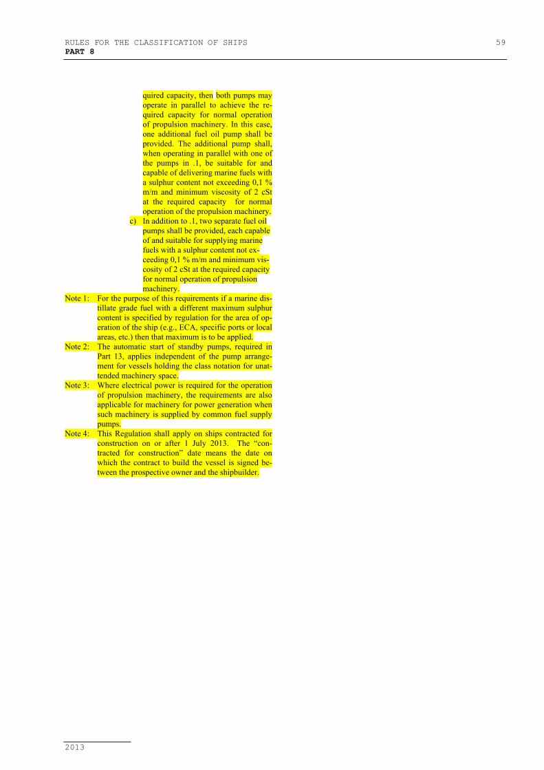
RULES FOR THE CLASSIFICATION OF SHIPS 59PART 8
2013
quired capacity, then both pumps mayoperate in parallel to achieve the re-quired capacity for normal operationof propulsion machinery. In this case,one additional fuel oil pump shall beprovided. The additional pump shall,when operating in parallel with one ofthe pumps in .1, be suitable for andcapable of delivering marine fuels witha sulphur content not exceeding 0,1 %m/m and minimum viscosity of 2 cStat the required capacity for normaloperation of the propulsion machinery.
c) In addition to .1, two separate fuel oilpumps shall be provided, each capableof and suitable for supplying marinefuels with a sulphur content not ex-ceeding 0,1 % m/m and minimum vis-cosity of 2 cSt at the required capacityfor normal operation of propulsionmachinery.
Note 1: For the purpose of this requirements if a marine dis-tillate grade fuel with a different maximum sulphurcontent is specified by regulation for the area of op-eration of the ship (e.g., ECA, specific ports or localareas, etc.) then that maximum is to be applied.
Note 2: The automatic start of standby pumps, required inPart 13, applies independent of the pump arrange-ment for vessels holding the class notation for unat-tended machinery space.
Note 3: Where electrical power is required for the operationof propulsion machinery, the requirements are alsoapplicable for machinery for power generation whensuch machinery is supplied by common fuel supplypumps.
Note 4: This Regulation shall apply on ships contracted forconstruction on or after 1 July 2013. The “con-tracted for construction” date means the date onwhich the contract to build the vessel is signed be-tween the prospective owner and the shipbuilder.

60 RULES FOR THE CLASSIFICATION OF SHIPSPART 8
2013
9 LUBRICATING OIL SYSTEM
9.1 LUBRICATING OIL PUMPS OFINTERNAL COMBUSTION ENGINES,
GEARS AND COUPLINGS
9.1.1 For an installation with one propulsion engine atleast two lubricating oil pumps, main and standby pump, shallbe used for lubrication. One of these pumps may be drivenfrom the propulsion engine.
9.1.2 Where two propulsion engines are installed, itwill be sufficient that each of them is provided with its ownlubricating oil pump. Besides these two, provision shall bemade for one standby pump driven independently and havinga capacity sufficient to ensure the operation of each propul-sion engine.
The common lubricating oil system of propul-sion engines is, in each case, subject to special considerationby the Register.
9.1.3 The number and capacity of the oil pumps forthree or more propulsion engines are subject to special con-sideration by the Register.
9.1.4 In ships of restricted areas of navigation 5 to 8 ,the standby pumps may be omitted, whatever is the number ofpropulsion engines. This relaxation shall not apply to the fol-lowing ships of restricted navigation area 5:
.1 tugs with one propulsion engine,
.2 passenger ships with one propulsion en-gine.
9.1.5 Where the turbo-blowers of the propulsion en-gine have an independent electrically driven lubricating oilpump, provision shall be made for the standby pump of ade-quate capacity. The lubricating oil system shall be providedwith a gravity tank, the capacity of which is sufficient tomaintain lubrication of the turboblowers during idle rotation,if the oil pump stops working.
The tank shall be provided with warning alarmswhich shall operate for low level in the tank and automaticstart-up of standby pump shall be ensured at the stoppage ofthe main pump.
Means shall be provided to enable the oil flow inturbo-blower bearings to be controlled.
9.1.6 Lubricating oil pumps of main gearings, as wellas the pumps supplying the main fluid couplings, shall complywith requirements of 9.1.1-9.1.4 for propulsion engines.
9.1.7 Each auxiliary engine and emergency diesel-generator (see the Rules, Part 9 - Machinery, 2.2.9) shall havean independent lubricating system.
Common lubricating systems of the auxiliaryengines are, in each case, subject to special consideration bythe Register.
9.2 LUBRICATING OIL SUPPLYSYSTEM OF INTERNAL COMBUSTION
ENGINES AND GEARS
9.2.1 The ends of drain pipes from the engine crank-case shall be so arranged within the drain tank that they aresubmerged into lubricating oil all the time of the engine op-eration.
No communication is permitted between lubri-cating oil drain pipes of two or more engines.
9.2.2 The pipes of the lubricating oil system shall notcommunicate with other piping systems except in emergencycase when they are connected to the separators which may beused for fuel oil separation. The connection of lubricating oilpipe and fuel oil pipe shall be provided with the arrangementthat will preclude mixing of fuel oil and lubricating oil.
While separating lubricating oil, the precautionsshall be taken as to prevent mixing of lubricating oil for thepropulsion engine and auxiliary engines.
9.2.3 The efficient oil cleaning shall be anticipated inthe circulating oil system, and provision shall be made:
.1 on the suction side of the pump of thegears - magnetic filter,
.2 on the suction side of the pump - onecoarse filter,
.3 on pressure piping - two paralled filters orone duplex changeover filter or one self-cleaning filter.
9.2.4 With a common lubricating system of the engineand turbo-blower before turbo-blower sliding bearings, finefilters of a construction which enables cleaning without stop-ping oil circulation, shall be fitted. A pressure gauge shall befitted after the filters.
9.2.5 Capacity of each oil filter is to exceed by 10 percent the maximum capacity of the pump.
9.2.6 Lubricating oil system shall be fitted with con-trol and measuring instruments.
Pressure gauge, indicating the pressure in the oilcooler, shall be placed at the control station.
Sight-glasses in the piping shall have a suitabledegree of fire resistance.
9.3 LUBRICATING OIL PUMPS OFSTEAM TURBINES
9.3.1 The lubricating oil system of the propulsion tur-bine set shall be provided with two oil pumps. Each oil pumpshall have a capacity being sufficient to ensure lubrication ofthe turbine set for the maximum output condition.
At least one of the pumps shall be independentlydriven.
Where two propulsion turbine sets are arrangedin the same machinery space, one idependently driven standbypump may be fitted for both turbine sets.

RULES FOR THE CLASSIFICATION OF SHIPS 61PART 8
2013
9.3.2 Lubricating oil pumps shall be of self-primingtype and shall be so disposed that reliable start-up is alwayspossible.
9.3.3 As a rule, the lubricating oil for propulsion tur-bine sets shall be supplied from the tank by gravity. Precau-tions shall be taken to ensure the lubrication of the propulsionturbine in the event of damage of the main lubricating oilpump, as well as in the case the turbine comes to the rest atfailure in power supply from the main sources of power to themotors of oil pumps.
The use of lubrication system shall be consid-ered by the Register in each case.
9.4 LUBRICATING OIL SUPPLYSYSTEM OF STEAM TURBINES AND
GEARS
9.4.1 The lubricating oil pipeline, including all branchpipes, shall be made of copper, copper-nickel or otherequivalent materials.
9.4.2 Oil may be taken from the propulsion turbinelubricating system only for control, adjustment and protectionneeds, as well as for lubricating the propulsion thrust bearing.
9.4.3 Each lubricating system shall be fitted withaudible and visual alarms warning of oil pressure drop andplaced at the propulsion turbine control station. In the oilgravity system the alarms shall operate at such level in thegravity tank as to enable the protection arrangements to cut inthe standby or emergency pump during the time left before thetank is emptied.
9.4.4 The capacity of the gravity tank in the lubricat-ing gravity system shall be not less than a 5-minute consump-tion of oil when the turbine is running at the rated output.
The tank shall be fitted with an overflow pipewith a sight glass well lighted and visible from the controlstation. The cross-sectional area of the overflow pipe shall benot less than 1,25 times that of the discharge of the pump.
The possibility of supplying lubricating oil toconsumers from the pump, except the tank, shall be provided.
9.4.5 The lubrication system of the propulsion turbineset shall be fitted with two oil coolers, one of which is astandby cooler.
Where two turbine sets are situated in the samemachinery space, one standby oil cooler may be installed forboth turbine sets.
Servicing of oil coolers shall be provided ac-cording to 10.1.7.
9.4.6 The lubricating system of the main turbines andtheir gears shall also comply with the requirements set forth in9.1.6, 9.2.3 and 9.2.6.
9.4.7 The branches of the lubricating oil pipeline shallbe fitted with throttles for regulating the amount of oil sup-plied to each consumer.
9.5 LUBRICATING OIL TANKS
9.5.1 Lubricating oil tanks shall be separated from thefeed water, boiler water, vegetable oil and oil fuel tanks bycofferdams which shall comply with requirements of theRules, Part 2 - Hull, 17.3.2.
9.5.2 Lubricating oil drain tanks of main turbines andmain diesel engines of ships of ice categories 1AS, as well asof icebreakers, shall be separated from the bottom shell plat-ing by a cofferdam conforming to the requirements of theRules, Part 2 - Hull, 7.13.2.
For other ships, the arrangement of cofferdamsis recommended.
Where the cofferdams are not available, thedrain pipes from crankcases shall have non-return or shut-offvalves capable of being operated from above the engine floorplating.
9.5.3 Provision shall be made for a lubricating oilstorage tank. The capacity of this tank shall be sufficient forfilling the system with oil to the working condition.
It is advisable to arrange the tank outside thedouble bottom.
In ships of restricted areas of navigation 5 to 8,the storage tank is not required to be fitted.
9.5.4 Suction pipes from the tanks situated outside thedouble bottom shall be fitted with shut-off valves installed di-rectly on the tanks.
Such valves installed on tanks having a capacityof more than 500 lit, which under normal service conditionsmay be in the open position, shall be capable of being re-motely closed from always accessible places located outsidethe space containing the tank.
9.5.5 Arrangements for heating of the lubricating oilshall comply with requirements of 8.3.
9.5.6 The oil tanks located in category A engine room(see the Rules, Part 7 - Machinery Installations, 1.2.5) or inother machinery spaces shall comply with the requirements of8.5.1 and the Rules, Part 7 - Machinery Installations, 1.2.5.
9.6 ARRANGEMENTS FORCOLLECTION OF LEAKAGE OIL
9.6.1 In unattended machinery spaces the same re-quirements as for fuel oil systems are valid according to 8.5.
9.7 LUBRICATING OIL SYSTEM OFGAS TURBINE
9.7.1 Gas turbine lubricating shall comply with therequirements of 9.1 to 9.5, where applicable.
9.7.2 Lubrication system of the gas turbine may beused for cooling the gas chamber pistons.
9.7.3 Lubricating system of gas chamber pistons shallbe separated from other lubricating systems. Lubricants shallcomply with the Rules, Part 9 - Machinery, 2.7.

62 RULES FOR THE CLASSIFICATION OF SHIPSPART 8
2013
10 COOLING WATER SYSTEM
10.1 PUMPS
10.1.1 As a general rule, means shall be provided incooling systems whereby normal operation of propulsion ma-chinery can be sustained or restored even though one ofsources of cooling media pressure becomes inoperative.
In that order, the cooling water systems of mainengines shall comply with the following requirements:
.1 A seawater cooling system of one mainengine shall include two cooling waterpumps, one of, which is standby. The ca-pacity of the standby pump shall be notless than that of the main pump. At least,one pump shall be driven independently.A fresh water cooling system of one mainengine is also to comply with these re-quirements. One common independentstandby pump may be used for both freshand sea water cooling. Precautions shall betaken to prevent mixing of fresh and sea-water.
.2 One independent standby pump ensuringthe operation of each engine running atmaximum load shall be installed in a seawater cooling system of two and moremain engines, each served by a separatecooling water pump.A fresh water cooling system shall alsocomply with these requirements. It is per-mitted to install one common independentstandby pump, the capacity of which shallensure cooling of any engine. Precautionsshall be taken to prevent mixing of freshand seawater.
.3 It is allowed to cool several engines byone independently driven pump. In thiscase, the capacity of the pump shall be suf-ficient for simultaneous cooling of all en-gines when running at maximum load.One standby pump, the capacity of whichshall be not less than that of the mainpump cooling simultaneously all engines,shall be provided.The cooling pipe shall have a water con-trol valve at inlet to each engine.
.4 In the installations on ships with an auto-mation mark in the class notation, provi-sion shall be made for separate fresh waterand sea water standby pumps, the capacityof which shall be not less than that of themain pumps.
.5 Except for passenger ships, above men-tioned special standby facilities are notmandatory for ships with restricted areasof navigation 5 to 8. However, the ar-rangement shall be provided for emer-gency condition to enable the cooling ofthe engine by sea water directly.
Where two and more propulsion enginesare installed, the emergency solution forcooling by sea water directly is not man-datory.The requirement for alternative cooling inemergency condition by sea water directlycould be also dispensed with for a singlepropulsion engine where justified that thefresh water pump is a gear driven pumpattached to the engine. Subject to a specialconsideration for each particular case
10.1.2 The oil and air coolers of the electric propellingmotors shall have standby means of cooling, equivalent to themain means.
10.1.3 Where each of the auxiliary engines is providedwith an independent cooling water pump, the standby pumpsfor these engines are not required. Where, however, a group ofauxiliaries is supplied with cooling water from a commonsystem, one standby pump for sea water and fresh water issufficient.
In a common system of cooling the propulsionand auxiliary engines, standby pumps for cooling the auxiliaryengines are not required.
For the diesel generators kept ready for immedi-ate use, continuous priming with hot water shall be provided,where necessary.
10.1.4 Ballast pumps other general service pumps op-erated only for clean water and fire pumps may be used asstandby cooling pumps.
10.1.5 An independent pistons cooling system shall in-clude a standby pump with capacity not less than that of themain pump.
10.1.6 An independent fuel valves cooling system shallinclude a standby pump with a capacity not less than that ofthe main pump.
10.1.7 The oil coolers of main turbo-generators, as arule, shall use main condenser circulating pump.
Where a separate pump is provided, a stand-bypump of a capacity at least 0,66 capacity of main pump in op-eration with the calculated power of turbogenerator, shall beprovided.
Each common pump may be used as a stand-bypump.
10.2 PIPING ARRANGEMENT
10.2.1 Sea water for cooling system shall be taken fromat least two sea inlet boxes, arranged in engine room, one ofwhich is placed at the side and the other at the bottom of theship. These boxes shall be interconnected.
10.2.2 It is recommended that the cooling system serv-icing the auxiliary engines and condensers of auxiliary tur-bines shall be supplied with water from separate sea inlet box.Where these sea inlet boxes are located in the engine room,the suctions of the above mentioned systems shall be con-nected by means of shut-off valves to the cooling main sup-plied from sea inlet boxes according to 10.2.1

RULES FOR THE CLASSIFICATION OF SHIPS 63PART 8
2013
10.2.3 For heating of sea inlet boxes in ships with icestrenghtening, see 1.5.1.2.
10.3 COOLING WATER FILTERS
10.3.1 On the suction lines of water cooling systemservicing the propulsion and auxiliary internal combustion en-gines, the filters shall be fitted behind the sea inlet boxes.
The sea inlet boxes and piping systems shall bearranged so as to enable the filters to be cleaned without hav-ing to stop the cooling pumps.
In a water cooling system of a turbine installa-tion, filters are recommended to be fitted.
10.4 COOLING OF INTERNALCOMBUSTION ENGINES
10.4.1 In a fresh water cooling system of the engine,provision shall be made for an expansion tank where the levelof water is higher than the maximum level of water in the en-gine. The expansion tank shall be connected to the suctionpiping of the pumps and may be common for the cooling sys-tem of several engines.
The tank shall be provided with a device formonitoring the water level.
In the cooling system of engines, the arrange-ment of the sea water discharge pipes shall be such that thehighest cooled spaces of the engines, air coolers and oil cool-ers are always filled with water and formation of trappedzones is excluded.
10.4.2 The cooling system shall be fitted with ther-mometers and temperature control devices.
It is recommended that suitable alarms shall beprovided to warn of the limit value of the cooling water tem-perature.
10.4.3 Cooling system for the emergency engine shallbe in compliance with the Rules, Part 9 - Machines, 2.2.6.
10.4.4 Where fuel oil or lubricating oil is used in cool-ing systems of injectors or pistons, this system shall complywith the Chapters 8 and 9.
10.5 COOLING OF GAS TURBINESYSTEMS
10.5.1 Cooling system of gas turbine shall comply withthe requirements of 10.4.
10.5.2 Fresh water shall be used for the cooling systemand sea water may be used only in emergency.
10.5.3 Air cooling system shall comply with the re-quirements of 14.2.1, 14.2.3 and 14.3.1.
If in case of the of water cooling failure, the tur-bine operation with 30% of the calculated power is ensured,stand by pump is not necessary.

64 RULES FOR THE CLASSIFICATION OF SHIPSPART 8
2013
11 COMPRESSED AIR SYSTEM
11.1 NUMBER AND CAPACITY OFSTARTING AIR RECEIVERS
11.1.1 The arrangement for air starting is to be suchthat the necessary air for the first charge can be produced onboard without external aid.
Compressed air system of propulsion enginesshall be of such a construction as to ensure simultaneousstarting and reversing of all propulsion engines.
For the starting system of gas turbines see theRules, Part 9 - Machines, 8.1.9.
11.1.2 The starting air of the propulsion engines andthe associated pneumatic control systems shall be stored in notless than two independent air receivers or in two independentgroups of several air receivers. Each of these two air receiversor each group of them shall have a capacity sufficient to pro-vide starting air in the amount not less than 50 per cent of thatrequired in 11.1.3, 11.1.4 and 11.1.6.
In ships of restricted areas of navigation 5 to 8,where an electric siren is used it is permitted to fit one air re-ceiver of a capacity sufficient to meet the requirements of11.1.3 and 11.1.4.
11.1.3 The total capacity of the air receivers for startingand reversing of the propulsion engines shall ensure not lessthan 12 consecutive starts alternating between ahead andastern speed of each cold and ready to start conditions, as wellas the function of control systems.
For ships with ice strengthening of the category1AS and for icebreakers the total capacity of the air receiversis subject to special consideration by the Register in each case.
11.1.4 The total capacity of air receivers for starting ofthe main engines connected to a controllable pitch propeller orsome other device, enabling to start without opposite torque,shall be sufficient to provide not less than 6 starts of each en-gine being in cold and ready to start conditions, and wherethere are more than two engines, at least 3 starts of each en-gine. At the same time, the function of engine control air sys-tems shall be provided.
11.1.5 For starting of the auxiliary engines provisionshall be made for at least one air receiver with a capacity suf-ficient for carrying out 6 starts of the engine of maximum out-put, in cold and ready to start conditions.
Where one air receiver is available, it shall bepossible to start the auxiliary engines from one air receiver ora group of air receivers of the propulsion engines. In specialagreement with the Register such air receiver may be dis-pensed with.
11.1.6 It is permitted that the starting air stored in oneair receiver or in a group of air receivers of the propulsion en-gines according to 11.1.2 is used to feed the tyfon whistle andother needs of the ship, provided the capacity of the air re-ceiver is increased by an amount of air specified below forspecial air receiver of the tyfon, or where the air receiver isfitted with automatic replenishing means or with warning
alarms, which shall operate as soon as the pressure in the airreceiver goes down by not more than 0,5 MPa below theworking pressure.
Where an air receiver is fitted especially for thetyfon, its capacity shall be determined so that the tyfon will beable to work continuously for 2 min. An hourly performanceof compressor shall be not less than that required to providecontinuous operation of tyfon during 8 min.
Where an air receiver is anticipated to feed thetyfon and control systems, as well as for other ship purposes,the capacity of the air receiver shall be increased as comparedwith that designed for tyfon only. Provision shall be made forautomatic replenishing or signalling means which shall oper-ate as soon as the amount of air in the air receiver is such asrequired for tyfon only.
In ships having mark of automation replenishingof air receivers shall be in compliance with the requirementsof the Rules, Part 13 - Automation, 4.2.1, 5.1.10 and 6.2.2.
11.1.7 The air receivers of auxiliary engines indicatedin 11.1.5 may be replenished from the propulsion air receiversstated in 11.1.6. Any possibility of back flow shall be ex-cluded.
11.1.8 Where compressed air is used for starting anemergency diesel-generator, in compliance with the require-ments of the Rules, Part 12 - Electrical Equipment, 9.5.1.2,following requirements shall be fulfilled:
1 Starting system shall be provided with ap-proved starting device and a compressedair receiver arranged for this purpose only.
.2 Compressed air in the starting air receivershall be sufficient for at least three con-secutive starts at all times.
.3 Provisions shall be provided for main-taining required air capacity in the receiverat all times. For this purpose, compressedair starting systems may be maintained bythe main or auxiliary compressed air re-ceivers, through a suitable non-returnvalve, or by an emergency air compressorenergised by the emergency switchboard.
.4 All these starting, charging and com-pressed air storing devices shall be locatedin the emergency generator room, in com-pliance with the requirements of the Rules,Part 12 - Electrical Equipment, 9.2.5.
.5 When the emergency diesel-generator isstarted by means of compressed air systemonly, two air receivers shall be provided.Capacity of each shall be sufficient for atleast three consecutive starts.
11.2 COMPRESSORS
11.2.1 In ships of areas of navigation 1 or 4 (H) thereshall be not less than two main compressors. One of them maybe driven from main engine.
The compressors shall have sufficient capacityto fill the main air receivers during one hour, begining fromthe atmospheric pressure, to a pressure that is necessary for
RULES FOR THE CLASSIFICATION OF SHIPS 65PART 8
2013
carrying out the full number of starts and manoeuvres indi-cated in 11.1.3 and 11.1.4.
The capacity of the independently driven com-pressors shall be not less than 50 per cent of that required ofall the main compressors, but not less than the air consump-tion for the whistle according to 11.1.6.
For ships with reversible engines with ice cate-gory 1AS, as well as in icebreakers, the number and capacityof compressors are, in each case, subject to special considera-tion by the Register.
11.2.2 In ships of restricted areas of navigation 6, 7 and8 with reversible propulsion engines, it is permitted to installone independently driven compressor, whereas in ships withpropulsion engines of non-reversible type, one attached com-pressor.
The capacity of compressors or gas take-off ar-rangements shall comply with requirements set forth in 11.2.1.
11.2.3 In ships of areas of navigation 1 or 2 servicewith propulsion and auxiliary engines arranged for com-pressed air starting, provision shall be made for the possibilityof starting the main compressors during not more than onehour.
For this purpose it is allowed to use a hand com-pressor or a diesel-compressor with a hand-started engine, tofill a separate air receiver whose capacity shall be sufficient tostart three times one of the diesel-generators or one of themain compressors where they are driven by an internal com-bustion engine.
A separate air receiver may not be installedwhere the diesel-compressor or hand compressor is capable offilling the smallest of the air receivers specified in 11.1.5during the aforesaid time period.
Where the electromotor of one of the compres-sors specified in this text can be supplied from the emergencydiesel-generator, the arrangement described hereinbefore maybe omitted.
11.2.4 The compressors shall be provided with safetyarrangements in accordance with the Rules, Part 9 - Ma-chines, 5.1.2.
11.3 PIPING ARRANGEMENT
11.3.1 Pipes intended for filling air receivers shall beled directly from the compressor to the air receiver and shallbe completely separate from the starting air pipes.
11.3.2 Each of the starting air receivers specified in11.1 shall be capable of being filled from each main compres-sor specified in 11.2. For air receivers interconnection, see11.1.7.
11.3.3 Non-return shut-off valves shall be installed onthe discharge pipes, behind each compressor.
The piping supplying starting air to each engineshall have a non-return valve installed before the startingvalve.
The non-return valve may be omitted, if provi-sion is made in the engine design for suitable safety devices
protecting the piping from the effects of an internal explosion(see the Rules, Part 9 - Machines, 2.9.1).
11.3.4 The temperature of air entering the receivers,shall not exceed 90oC. Where required, provison shall bemade for appropriate coolers.
The compressed gas piping shall not be led un-der the engine room floor plating.
11.3.5 The compressed air pipings shall be led asstraight as possible with a slope for water drainage. The pipesshall not have a slope in the direction of the master startingvalve of the engine.
11.3.6 Suitable arrangements for separating accumula-tions of oil and water shall be fitted on the pipes betweencompressors and receivers, unless draining arrangements arefitted on the compressors.
11.3.7 Means shall be provided to prevent overpressurein any part of compressed air systems.
If air is led from a safety valve or a safety plugof air receivers outside the machinery space, the pipeline crosssection shall not be less than twice the cross sectional area ofa safety valve or a safety plug.
Suitable arrangements for water drain shall beprovided on the pipeline.
11.3.8 Pneumatic sound devices of the alarm systemstipulated by the Rules, Part 12 - Electrical Equipment, 7.4,shall be connected to starting air receiver by means of specialpiping".

66 RULES FOR THE CLASSIFICATION OF SHIPSPART 8
2013
12 FEED WATER SYSTEM
12.1 PUMPS
12.1.1 Each main boiler and an essential auxiliaryboiler or a group of boilers shall be provided with at least twoindependent feed pumps.
For uxiliary boilers which are not intended foressential services, as well as for exhaust gas boilers so con-structed that they can be left without water when heated byexhaust gases, one feed pump is sufficient.
For boilers with manual feed regulation the ca-pacity of each pump shall be not less than 1,5 times the ratedcapacity of the boilers, and for boilers with automatic controlsystems, not less than 1,15 times their rated capacity.
Where several feed pumps are installed, theiradopted capacity shall be such that in the event of failure ofany of the pumps the total capacity of the rest of the pumps isnot less than the capacity required in the foregoing for eachpump.
The capacity of each feed pump of a straight-through boiler shall be not less than the rated capacity of theboiler.
12.1.2 In the case of steam driven feed pumps, livesteam shall be supplied to the separate pipeline having con-nections from all the boilers fed by these pump.
12.1.3 The main and essential auxiliary boilers withforced circulation shall be serviced by not less than two cir-culating pumps, one of which is a standby pump.
12.2 PIPING ARRANGEMENT
12.2.1 In open circuit feed systems the feed pumps andinjectors shall be provided with suctions from the hot well andfrom the feed water storage tanks.
12.2.2 Every steam generating system which providesservices essential for the safety of the ship, or which could berendered dangerous by the failure of its feedwater supply,shall be provided with not less than two separate feedwatersystems from and including the feed pumps, noting that a sin-gle penetration of the steam drum is acceptable.
Where a steam generation system consists oftwo or more adequately sized boilers, and the feed water foreach of these boilers is supplied by a single feed water pipe,the level of redundancy for the piping of the feedwater systemmay be considered to comply with the requirement above.
See also requirements in the Rules Part 10, item3.3.2.
12.2.3 Structural measures shall be taken to prevent thefeed water being contaminated by oil and oily water.
12.2.4 Unless overpressure is prevented by the pumpcharacteristics, means shall be provided which will preventoverpressure in any part of the feedwater systems.
12.3 TANKS
12.3.1 Feed water tanks shall be separated from tankscontaining fuel oil, lubricating oil and vegetable oil by coffer-dams. These cofferdams shall be in compliance with require-ments of the Rules, Part 2 - Hull, 18.3.2.

RULES FOR THE CLASSIFICATION OF SHIPS 67PART 8
2013
13 STEAM AND BLOW-OFFSYSTEMS
13.1 PIPING ARRANGEMENT
13.1.1 Where two or more boilers are connected to acommon steam line, a non-return valve shall be fitted on thesteam pipe of each boiler before connection to the commonline. These valves may not be fitted if the stop valves of theboilers are of non-return shut-off type.
13.1.2 The blow-down and the scum valves of two ormore boilers may be connected to a common discharge, pro-vided a non-return valve is fitted between each boiler and acommon discharge.
13.1.3 Steam for the ship's whistle shall be suppliedthrough a separate line directly from the main boiler. This re-quirement does not apply to ships having, besides steamwhistle, pneumatically or electrically operated sound signalmeans.
13.1.4 The machinery connected with the steam linesshall be relieved of the stresses caused by thermal expansionpipes, by means of pipelines provided with compensators forthermal expansion or pipes bends.
13.1.5 In the steam line supplying machinery and ar-rangements designed for a lower pressure than the boiler pres-sure, reducing valves shall be fitted and requirements of1.3.5.2 shall be complied with.
13.1.6 The branches of the steaming system and steamsmothering system of the fuel and cargo oil tanks shall be fit-ted with shut-off non-return valves for each tank.
13.1.7 The steam pipelines in the engine and boilerrooms shall be led in the upper parts of these spaces, wherepracticable, in a position accessible for observation and serv-icing.
Leading of steam lines under the floor plating ofengine and boiler rooms, with the exception of boiler heatingcoils and blow-off pipes, is not permitted.
Steam lines shall not be led near the fuel oiltanks.
On oil tankers, the steam temperature within thecargo area is not to exceed 220 °C, complying with the re-quirements of 4.2.9. On gas carriers and chemical tankers, themaximum temperature is to be adjusted to take into accountthe temperature characteristic of the cargoes.
13.2 BLOW-OFF ARRANGEMENTS OFSTEAM LINES
13.2.1 Pipelines conveying live steam shall have con-densate drain arrangements to protect the machinery againstwater hammer.
13.2.2 The open ends of the pipelines for steam lineblow-off shall be led below the flooring of the engine andboiler rooms (see 1.6.3.8).
13.3 CALCULATION OF THERMALEXPANSION OF STEAM PIPES
13.3.1 Calculation of thermal expansion of steam pipesshall be based on the methods generally adopted in structuralmechanics for computing statically indeterminate beem sys-tems, performed mannually, or by means of an electroniccomputer or by means of a model method.
13.3.2 Calculation of thermal expansion of steam pipesshall include a summary table of stresses and safety factors forall the pipe ranges dealt with in the calculation.
Steam pipes working on temperatures which donot cause stress relaxation, shall, as a rule, be calculated forthermal expansion taking into account the prestressing in coldcondition and during its installment on the platform.
Steam pipes working under conditions of stressrelaxation shall be calculated in cold condition for a 100%prestressing, considered as great as the displacements due tofull thermal expansion (displacements of supports included)but with an opposite sign. Where a steam pipe in hot conditionundergoes displacements, it shall be calculated in view ofthese displacements, and, after that, for a 100% prestressing incold condition (displacements of supports included).
Note:The temperatures which cause the pipes to relax
are as follows:350oC and over - for carbon steel pipes420oC and over - for alloy steel pipes.
13.3.3 In the calculation of thermal expansion the pipefittings and joining parts (elbows, T-joints, etc.) may be as-sumed rigid and need not be calculated.
13.3.4 The internal forces in steam pipes shall be cal-culated depending on the pipe cross-sectional area, includingthe positive manufacturing tolerances for pipe wall thickness.The same sizes shall be used for determining the stresses fromdisplacements.The stresses caused by internal pressure, shallbe determined depending on pipe cross-sectional area, in-cluding the negative manufacturing tolerance for pipe wallthickness.
13.3.5 For all types of butt joints of steam pipes weldedwith a back sealing run at the root, butt joints welded fromboth sides and made by automatic submerged arc welding, in-cluding joints welded on a removable backing ring, with sur-face dressing, the efficiency factor in the formula for stresscalculation of piping may be assumed equal to 1, i.e. ϕ = 1.
13.3.6 The three components of reaction for a planeframe in general and the six components for a space frameshall be determined by methods applied in calculation of stati-caly indeterminate beam system.
13.3.7 The flexibility coefficient k of the curved por-tion shall be determined by the formulae:
For λ ≥ 0,4 k = 10 121 12
2
2+ ⋅
+ ⋅
λ
λ(13.3.7-1)
and for 0,2 ≤ 0,4 λ < 0,4 k = 1 65,λ
(13.3.7-2)
68 RULES FOR THE CLASSIFICATION OF SHIPSPART 8
2013
where:
λ = 2rRs ⋅− geometrical coefficient of bent pipe;
s − wall thickness of straight pipe, [mm];R − bending radius of the curved portion,
[mm];r − average radius of cross-section of a
straight pipe, [mm].
13.3.8 In calculating the steam pipes for thermal ex-pansion, the maximum stresses shall be determined as follows:
− equivalent stress for a straight pipe convey-ing hot steam subjected to working pressure,as well as for cold pipe not subjected to in-ternal pressure;
− total local stress acting on the inside of abent pipe conveying hot steam subjected toworking pressure, as well as for cold pipenot subjected to internal pressure.
Bent pipes with λ ≥ 1.44 may be regarded asstraight, when determining the equivalent stress, and need notto be calculated for the total local stress.
When the assembled steam pipeline is subjectedto a hydraulic test on board ship, the resultant stresses shall bedetermined also for a cold pipeline at the hydraulic test pres-sure.
13.3.9 The resultant stress in a straight pipe when ex-posed to internal pressure and to the bending and torsionalmoments are determined by the formula
στ = σ σ σ σ σ σ σ σ σ στa a a2
22
32
2 3 2 32+ + − − − + (13.3.9)
where:σa − total normal stress from bending and inter-
nal pressure, [N/mm2],σ2 − circumferential stress due to internal press-
ure, [N/mm2],σ3 − radial stress due to internal pressure,
[N/mm2],στ − shearing stress, [N/mm2].
13.3.10 The total local stress acting on the inside of abent pipe shall be determined in all cases of bending (in planeand perpendicular to curvature plane of a bent pipe) as a sumof bending stresses and circumferential stress due to internalpressure.
13.3.11 Safety factors, relating to the yield point or totensile strength, used for determination of permissible stresses,to which the resultant and local stresses are compared are asfollows:
1,2 − for plane frame;1,5 − for space frame.

RULES FOR THE CLASSIFICATION OF SHIPS 69PART 8
2013
14 CONDENSER SYSTEM
14.1 GENERAL
14.1.1 Each propulsion turbine set shall be fitted withan independent condenser installation ensuring a stable vac-uum under all rated operating conditions.
Auxiliary turbines�may have a common con-denser installation. In running conditions, waste steam fromthe auxiliary turbo-generators may be discharged into themain condenser or into the stages of the propulsion turbineset.
14.2 PUMPS
14.2.1 The main condenser shall be cooled by two seawater pumps one of which is a standby pump.
The capacity of standby pump shall be not lessthan 30 per cent of rated quantity of circulating water for allconsumers.
Any pump of sufficient capacity may be used asa standby pump.
In twin-screw ships it is allowed to use onestandby sea water pump for cooling the condensers of bothturbine sets.
Where, for servicing the main condenser, provi-sion is made for simultaneous operation of both pumps, thecapacity of each pump shall be not less than 50 per cent of therated quantity of circulating water for all consumers. Nostandby sea water pump is required in this case.
14.2.2 Where the auxiliary condenser is common for allthe turbo-generators, it shall be serviced by two circulatingpumps one of which is a standby pump. Any pump of a suffi-cient capacity may be used as a standby pump.
14.2.3 Scoop circulating of cooling water may be al-lowed, provided there is a circulating pump with a capacitysufficient to ensure full astern conditions speed. The standbycirculating pump shall meet the requirements of 14.2.1.
14.2.4 The condensate system of a steam turbine in-stallation shall be serviced by two condensate pumps, one ofwhich is a standby pump.
The capacity of each pump shall be not less than1,25 of the maximum permissible amount of the condensatedsteam.
For the propulsion turbines with two main con-densers arranged in the same engine room, the standby con-densate pump may be common for both condensers.
14.3 PIPING ARRANGEMENTS
14.3.1 The arrangement of pipes and their connectionsshall comply with requirements of 10.2 and 10.3.
14.3.2 The condensate collector, discharge pipe andcondensate pump shall be so arranged as to preclude floodingof the lower rows of pipes and to ensure the required pressure
and smooth delivery of condensate to the pump. Provisionshall be made for a handhole for cleaning the collector.
14.3.3 The nozzles of the ejectors of the condenser in-stallations shall be protected against damage and clogging.For this purpose, a metal screen shall be installed on the steampipeline.
14.4 INSTRUMENTATION
14.4.1 The condenser system for steam turbine instal-lations shall be fitted with the following gauges, alarm andsignal devices:
1. a condensate level indicator for the con-denser;
2. vacuum and vacuum pressure gauges forthe condenser and ejector coolers;
3. a pressure gauge for the steam pipeline toejector;
4. thermometers for the cooling water dis-charge pipes of the condenser and ejectorcoolers;
5. salinometers with light and sound alarmsindicating condensate salinity.
70 RULES FOR THE CLASSIFICATION OF SHIPSPART 8
2013
15 SYSTEMS WITH THERMALFLUIDS BASED ON MINERAL
OILS
15.1 PUMPS
15.1.1 At least two circulating pumps shall be providedfor thermal oil one of which shall be a stand-by pump.
15.1.2 Gauges shall be fitted at the thermal oil outlets.
15.1.3 A transfer pump shall be provided for filling thesystem as well as thermal oil transfer.
15.1.4 Thermal oil pumps shall be provided with dis-connecting switches in compliance with the requirements ofthe Rules, Part 12 - Electrical Equipment, 5.7.
15.2 EXPANSION TANKS
15.2.1 An expansion tank shall be provided in thermaloil systems.
Tank capacity shall be at least 1,5 times greaterthan the increased volume of the thermal oil resulted from itsheating to the working temperature. An expansion tank shallbe fitted at the highest level of the thermal oil system.
15.2.2 The expansion tank shall be provided with thelevel indicator in compliance with the requirements of 5.5.2.
The level indicator shall be marked for the low-est permissible thermal oil level.
15.2.3 The expansion tank shall be provided with anoverflow pipe leading to the oil storage tank or overflow tank.
15.2.4 The overflow tank shall be provided with thehigh and low level alarm. When the level of oil is below thepermissible limit, the heating of thermal oil shall be automati-cally stopped.
15.2.5 The expansion tank of the system in the area ofinert gas shall be provided with gauges and safety valves (re-lief valves).
15.2.6 Provision shall be made for a device for vapoursand gases passing through piping to the expansion tank.
15.3 OIL STORAGE TANKS
15.3.1 Capacity of oil storage tank shall be sufficient tofill up with thermal oil the part of the system having the great-est volume.
15.3.2 Where the oil storage tank is used for the dis-charge of thermal oil from the system , its capacity shall besufficient to accept the discharged thermal oil and the oil stor-age stated under 15.3.1.
In that case the oil storage tank shall be so posi-tioned as the thermal oil can be discharged from the systeminto it.
15.4 LAYOUT OF PIPES
15.4.1 The thermal oil pipes shall be laid in compliancewith the requirements stated in 1.6 and 8.2.
15.5 VENT PIPES
15.5.1 Vent pipes of the thermal oil tanks shall complywith the requirements stated in 5.1.
15.6 ARRANGEMENTS FORCOLLECTION OF THERMAL OILLEAKAGE AND ITS DISCHARGE
15.6.1 Arrangements for collection of leakage of ther-mal oil shall be in compliance with 8.5.
15.6.2 Where the shut-off device stated in the Rules,Part 10 - Boilers, Heat exchangers and Pressure Vessels,3.5.7, is not provided with remote control, provision shall bemade for quick discharge of thermal oil from the system.
The thermal oil shall be discharged into draintank or a storage tank specified in 15.3.2.
15.6.3 Provision shall be made for the exhaust gas boil-ers that in case of oil thermal leakage is not permitted to enterinto the engine.
15.7 COOLING OF THERMAL OIL
15.7.1 Provision shall be made for cooling of thermaloil for the thermal oil systems which are provided with theexhaust gas boilers.
15.8 BOILERS FOR HEATING OFTHERMAL OILS
15.8.1 Boilers for heating of thermal oils shall be incompliance with the Rules, Part 10 - Boilers, Heat exchangersand Pressure Vessels, 3.5.
15.9 INSULATION
15.9.1 Insulation of piping and equipment shall complywith the requirements of the Rules, Part 7 - Machinery In-stallations, 1.11.9.
15.10HEATING OF LIQUID CARGO
15.10.1 The thermal oil system may be used for heatingof liquid cargoes with the flash point lower than 60oC, only ifthere is an intermmediate system located in the cargo zone.
15.11TESTS OF PIPING IN THERMALOIL SYSTEMS
15.11.1 The piping of thermal oil system shall be testedin acordance with 17.2 as the fuel oil pipes.

RULES FOR THE CLASSIFICATION OF SHIPS 71PART 8
2013
16 SCUPPERS, INLETS ANDDISCHARGES
16.1 SCUPPERS AND DISCHARGES.1 Discharges led through the shell either
from spaces below the freeboard deck orfrom within superstructures and deck-houses on the freeboard deck fitted withdoors complying with the requirements inLL 2003 reg. 12, shall be fitted with effi-cient and accessible means of preventingwater from passing inboard. Normally,each separate discharge shall have oneautomatic non-return valve with a positivemeans of closing it from a position abovethe freeboard deck.. Where the inboardend of the discharge pipe is located at least0.01L above the Summer Load Line, thedischarge may have two automatic non-return valves without positive means ofclosing. Where that vertical distance ex-ceeds 0.02L, a single automatic non-returnvalve without positive means of closingmay be accepted. The means for operatingthe positive action valves shall be readilyaccessible and provided with an indicatorshowing whether the valve is open orclosed.
.2 One automatic non-return valve and onesluice valve controlled from above thefreeboard deck instead of one automaticnon-return valve with a positive means ofclosing from a position above the free-board deck, is acceptable.
.3 Where two automatic non-return valvesare required, the inboard valve shall al-ways be accessible for examination underservice conditions (i.e., the inboard valveshall be above the level of the TropicalLoad Line). If this is not practicable, theinboard valve need not be located abovethe Tropical Load Line, provided that a lo-cally controlled sluice valve is fitted be-tween the two automatic non-returnvalves.
.4 Where sanitary discharges and scupperslead overboard through the shell in way ofmachinery spaces, a locally operated posi-tive closing valve at the shell, togetherwith a non-return valve inboard, is accept-able. The controls of the valves shall be inan easily accessible position.
.5 The position of the inboard end of dis-charges shall be related to the SummerTimber Load Line when a timber free-board is assigned.
.6 The requirements for non-return valves areapplicable only to those discharges whichremain open during the normal operationof ship. For discharges which are to be
kept closed at sea, a single screw downvalve operated from the deck is accept-able.
.7 Table 16.3 provides the acceptable ar-rangements of scuppers, inlets and dis-charges.
.8 Scuppers led through the shell from en-closed superstructures used for the car-riage of cargo shall be permitted onlywhere the edge of the freeboard deck isnot immersed when the ship heels 5o eitherway. In other cases the drainage shall beled inboard in accordance with the re-quirements of the International Conventionfor the Safety of Life at Sea in force.
.9 In manned machinery spaces, main andauxiliary sea inlets and discharges in con-nection with the operation of machinerymay be controlled locally. The controlsshall be readily accessible and shall beprovided with indicators showing whetherthe valves are open or closed.
.10 Scuppers and discharge pipes originatingat any level and penetrating the shell eithermore than 450 mm below the freeboarddeck or less than 600 mm above the Sum-mer Load Line shall be provided with anon-return valve at the shell. This valve,unless required by 16.1.8, may be omittedif the piping is of substantial thicknesscomplying with the requirements of 16.2.
.11 Scuppers leading from superstructures ordeckhouses not fitted with doors comply-ing with the requirements of LL 2003 reg.12 shall be led overboard.
.12 All shell fittings and valves required bythis regulation shall be of steel, bronze orother approved ductile material. Valves ofordinary cast iron or similar material arenot acceptable. All pipes to which thisregulation refers shall be of steel or otherequivalent material and in compliancewith the requirements of the Rules Part 25– Metallic Materials.
16.2 SCUPPER AND DISCHARGE PIPES.1 For scupper and discharge pipes, where
substantial thickness is not required:.1 for pipes having an external diameter
equal to or less than 155 mm, thethickness shall not be less than 4.5mm;
.2 for pipes having an external diameterequal to or more than 230 mm, thethickness shall not be less than 6 mm.
Intermediate sizes shall be determined bylinear interpolation or in compliance withtable 1.3.4.3, column 4.
.2 For scupper and discharge pipes, wheresubstantial thickness is required:
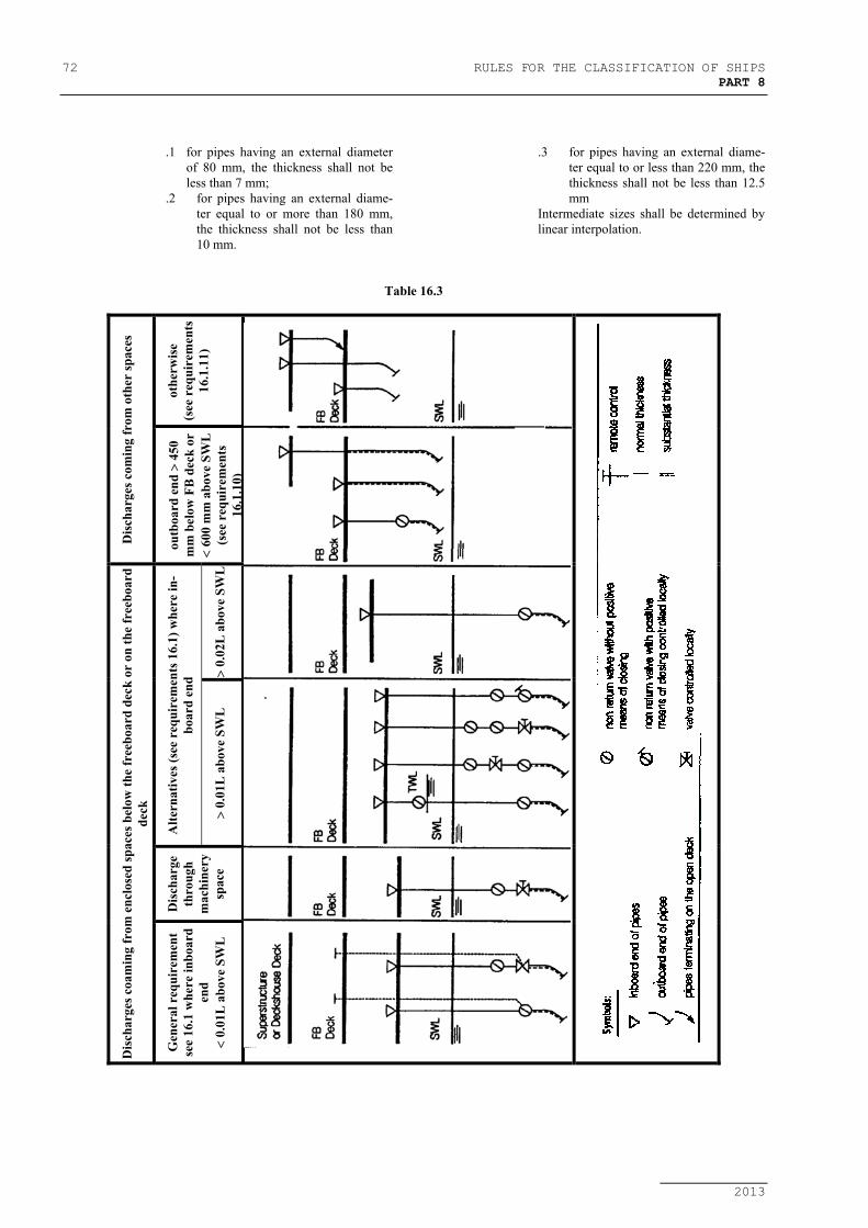
72 RULES FOR THE CLASSIFICATION OF SHIPSPART 8
2013
.1 for pipes having an external diameterof 80 mm, the thickness shall not beless than 7 mm;
.2 for pipes having an external diame-ter equal to or more than 180 mm,the thickness shall not be less than10 mm.
.3 for pipes having an external diame-ter equal to or less than 220 mm, thethickness shall not be less than 12.5mm
Intermediate sizes shall be determined bylinear interpolation.
Table 16.3
othe
rwis
e(s
ee r
equi
rem
ents
16.1
.11)
Dis
char
ges c
omin
g fr
om o
ther
spac
es
outb
oard
end
> 4
50m
m b
elow
FB
dec
k or
< 60
0 m
m a
bove
SW
L(s
ee r
equi
rem
ents
16.1
.10)
> 0.
02L
abo
ve S
WL
Alte
rnat
ives
(see
req
uire
men
ts 1
6.1)
whe
re in
-bo
ard
end
> 0.
01L
abo
ve S
WL
Dis
char
geth
roug
hm
achi
nery
spac
e
Dis
char
ges c
oam
ing
from
enc
lose
d sp
aces
bel
ow th
e fr
eebo
ard
deck
or
on th
e fr
eebo
ard
deck
Gen
eral
req
uire
men
tse
e 16
.1 w
here
inbo
ard
end
< 0.
01L
abo
ve S
WL

RULES FOR THE CLASSIFICATION OF SHIPS 73PART 8
2013
17 HYDRAULIC TESTS
17.1 HYDRAULIC TESTS OF VALVESAND FITTINGS
17.1.l The valves and fittings intended for Class I andClass II piping shall be subjected to a hydraulic test by thepressure indicated in the Rules, Part 9 - Machines, 1.3.1.
17.1.2 The valves and fittings intended for a designpressure of 0,1 MPa and less, as well as for vacuum, shall betested by a pressure not less than 0,2 [MPa].
17.1.3 The test pressure for the valves and fittings fittedon hull plating under load line shall be taken not less than 0,5[MPa].
17.1.4 After assembly, the valves and fittings shall bechecked for tightness by hydraulic pressure equal to the de-sign pressure.
17.2 HYDRAULIC TESTINGS OFPIPING
17.2.1 Piping of Class I and Class II, as well as steam,feed water, compressed air and fuel oil pipes having a designpressure over 0,35 [MPa] (irrespective of Class), after com-pletion and final machining but before insulation and coatingshall be subjected to a hydraulic test, in the presence of a Sur-veyor of the Register, with the following test pressure:
pis = 1,5 ⋅ p [MPa] (17.2.1-1)
where:p − maximum working pressure (see 1.3.4.1), [MPa].
The test pressure for steel pipes intended for de-sign temperatures over 300oC shall be determined from thefollowing formula:
pis/t = 1,5 ⋅σσd100
dt⋅ p ≤ 2p [MPa] (17.2.1-2)
where:σd100 − permissible stress at 100oC.σdt − permissible stress at design temperature.
Where during the test, excessive stress arises incertain lengths of the pipeline, then, in agreement with theRegister, the value of test pressure as obtained from formula(17.2.1-2) may be reduced to 1,5 p.
In no case shall the stresses arising during thetest exceed 0,9 of the yield point of the material at the tem-perature of testing.
17.2.2 When, for technical reasons, it is not possible tocarry out complete hydraulic tests for all sections of piping,proposals shall be submitted for approval to the Register fortesting of certain lengths of piping.
17.2.3 Pressure testing of small bore pipes (less than 15mm) of any Class may be omitted at discretion of the Regis-ter, depending on the application of these pipes.
17.2.4 All the piping systems shall be checked fortightness in operating conditions in the presence of a Surveyorto the Register, except for the following piping:
1. heating coils in tanks and liquid or gas fuellines shall be tested by 1,5 p, but not lessthan 0,4 [MPa].
2. liquefied gas pipelines shall be leak tested(by air, halogens, etc.) to a pressure cho-sen depending on the leak detectionmethod applied.
17.2.5 In case where hydraulic tests of an assembledpiping system are carried out on board, testing of piping forstrength and tightness may be combined.
17.2.6 The plastic pipelines in all piping systems cov-ered by classification, shall be tested in accordance with sub-items no. 1.7.6.9 and 1.7.6.10.