for the ADDA MECHANICAL DRAFTER CERTIFICATION · PDF fileii ADDA Drafter Certification Exam...
149
Copyright © ADDA International Review & Preparation Guide for the ADDA MECHANICAL DRAFTER CERTIFICATION EXAMINATION
Transcript of for the ADDA MECHANICAL DRAFTER CERTIFICATION · PDF fileii ADDA Drafter Certification Exam...

Copyright © ADDA International
Review & Preparation Guidefor the ADDA
MECHANICAL DRAFTER
CERTIFICATION EXAMINATION


©Copyright 2007 ADDA International
Basic Mechanical Drafter Certification Examination Review Guide
Copyright © 2007 ADDA International
105 East Main Street Newbern, Tennessee 38059
Third Edition Printing All rights reserved. This book, or parts thereof, may not be reproduced in any form or by any means including photocopying, recording, or microfilming or by any information storage and retrieval system, both print and digital, without permission in writing by the copyright owners. No liability is assumed by ADDA with respect to the use of the information contained herein. While every precaution has been taken in the preparation of this book, ADDA assumes no responsibility for errors or omissions.
The references listed below were used in part in the development of this guide and are useful to those preparing for the ADDA Certified Drafter Exam. Nevertheless, the ADDA is not promoting these books.
References
ASME Y14.2M-1992 Line Conventions and Lettering ASME Y14.3M-1994 Multiview and Sectional View Drawings ASME Y14.5M-1994 Dimensioning and Tolerancing Bertoline, Wiebe, Miller, Hohler, Technical Graphics Communication, 2nd edition, Irwin/McGraw-Hill Giesecke, Mitchell, Spencer, Hill, Dygdon, Novak, Technical Drawing. 11th edition, Prentice Hall Inc. Jensen, Helsel, Engineering Drawing and Design, 5th edition, Glencoe/McGraw-Hill Lamit, Technical Drawing and Design, West Publishing Madsen, Shumaker, Turpin, Stark, Engineering Drawing and Design, 2nd edition, Delmar-Thompson Learning


i
Our Mission
ADDA International shall promote excellence in and recognition of the design drafting and digital design professions.
ADDA's History
Established in 1948 as a drafting club and incorporated as the American Design Drafting Association in 1959 as an individual membership society, ADDA is pledged to meeting and serving the professional growth and advancement of the individual working in the design drafting and digital design communities. ADDA is the only membership organization exclusively for the profession in all disciplines including manufacturing, utilities, construction, engineering, government and education. ADDA is focused on the profession it represents and the enhancement of services our members provide to their employers.
Membership in ADDA is open to all individuals in the design graphics professions, including students, instructors, teachers, professionals and managers in industry, government and education. Corporate, Business and Sponsor Memberships are available on several levels offering a variety of options and benefits to a specified membership level.
Design Drafting News, helps keep ADDA members abreast of the rapidly transitioning work environment, computer-aided design drafting technologies, and quality management.
The Professional Certification Program is a nationwide program that allows individuals to demonstrate knowledge in concepts, standards and practices at several levels under various disciplines.
The Annual Technical Conference is focused entirely on the needs and interests of the professional and educator. The program features technical sessions to educate and inform participants.
The formation of Chapters is encouraged to motivate students toward pride in profession and personal responsibility as they acquire training. Through a national school curriculum certification program, ADDA assures that the variety and caliber of curriculum in participating schools is appropriate for the design drafting profession.
ADDA is the Premier Professional Organization for Drafters - Designers - Engineers - Architects - Illustrators
Graphics Artist - Digital Technicians - Digital Imaging Visual Communications & Multimedia

ii
ADDA Drafter Certification Exam
Drafter Certification is a nationwide program that allows drafters to show their knowledge in drafting concepts and nationally recognized standards and practices. ADDA developed the test to elevate the profession's standards. Certification enables drafters to demonstrate professional capabilities and helps employers in identifying quality employees.
• What Certification Means to a Drafter
Certification as a Drafter reflects your proven knowledge of drafting. You will receive a certificate suitable for framing. Your certification will:
• Enhance your credibility as a professional • Improve your opportunities for promotion and pay increases • Give you an edge in a highly competitive job market
• What Certification Means to an Employer
When you hire a Certified Drafter, you know that your new employee meets certification criteria and that he or she has demonstrated initiative and pride in the profession by becoming certified. Thus, certification can serve as one criterion for differentiating among candidates in the selection process.
• What Certification Means to Drafting Educators
Certification serves as a supplementary measurement of a student's performance on a recognized national level.
GET CERTIFIED!
Certification consists of completing the Application for Certification, and passing the Drafter Certification Test administered periodically at test sites throughout the country.
iii
ADDA Drafter Certification Exam
Exam Format
The exam is a "pass-fail" format. 75% correct responses are required to pass. It contains clear and concise true or false, multiple choice and matching questions. These formats are mixed, i.e., missing views identified by matching and/or multiple choice. The exam is not a drawing test nor does it require essay answers; therefore, answers are not subject to the grader's interpretation. The type of questions contained in the exam are: 1. Matching (a) Terms to definitions
(b) Graphic symbols to definition (c) Terms to graphic representations (d) Selection of correct pictorial representation to orthographic representation
2. True or False 3. Multiple Choice (a) Choose the correct missing views
(b) Choose the correct phrase to complete sentence Before taking the exam, it is recommended that a general review be completed using this review guide in conjunction with a quality drafting text book This guide will highlight the areas the exam covers, but is not all inclusive. No reference materials or calculators are allowed while taking the exam. The time allowed for the SCANTRON® scored or on-line Drafter Certification Exam is 120 minutes. The questions presented cover a wide assortment of situations normally encountered in the drafting profession. An individual's experience and education in drafting will be challenged with this exam. The exam does not require specific knowledge of design or of computer programs, but is a general knowledge examination designed to allow individuals to demonstrate their expertise in the drafting profession.
Eligibility
The ADDA Drafter Certification Program is open to all individuals, regardless of experience and formal education. Membership in ADDA is not required for you to take the test or become certified.
iv
ADDA Drafter Certification Exam
Exam Location
The Drafter Certification Exam are available at Testing Sites or through the approved ADDA Proctors. Email [email protected] or call the ADDA office at 731-627-0802 to make Testing arrangements.
Exam Application
An exam application may be found at the back of this study guide or may be obtained at the ADDA web site, www.adda.org or by calling the ADDA office at 731-627-0802.
Fill out the form and mail it with your check, money order, or credit card information to:
ADDA International 105 East Main Street
Newbern, Tennessee 38059
The references listed below would be useful to those preparing for the ADDA Certified Drafter Exam. Nevertheless, the ADDA is not promoting these books.
ASME Y14.2M-1992 Line Conventions and Lettering ASME Y14.3M-1994 Multiview and Sectional View Drawings ASME Y14.5M-1994 Dimensioning and Tolerancing Technical Graphics Communication, Authors -Bertoline, Wiebe, Miller, Hohler, Publishers - Irwin/McGraw-Hill Technical Drawing. Authors - Giesecke, Mitchell, Spencer, Hill, Dygdon, Novak, Publisher - Prentice Hall Inc. Engineering Drawing and Design, Authors - Jensen, Helsel, Publisher - Glencoe/McGraw-Hill Technical Drawing and Design, Author – Lamit Publisher - West Publishing Engineering Drawing and Design, Authors - Madsen, Shumaker, Turpin, Stark Publishers - Delmar-Thompson Learning
Become an ADDA Professional Member!
An application for membership in ADDA may be obtained at the ADDA web site, www.adda.org or by calling the ADDA office at 731-627-0802.
v
ADDA Drafter Certification Exam Sample Questions
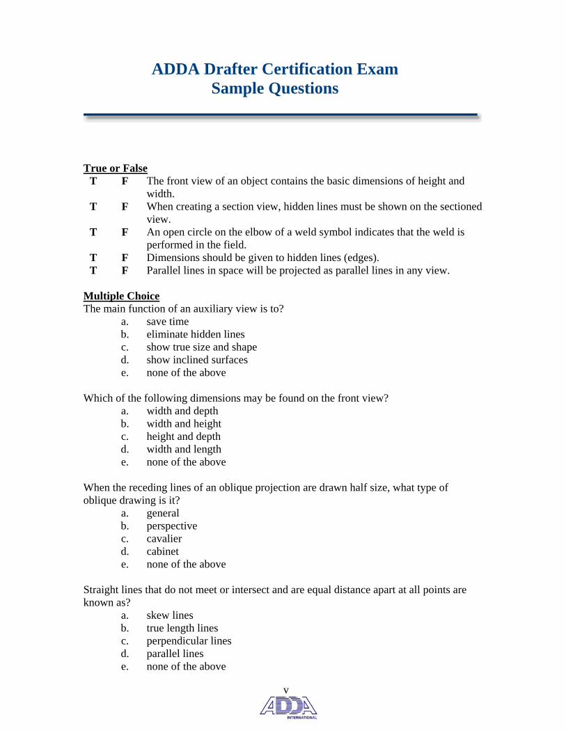
True or False
T F The front view of an object contains the basic dimensions of height and width.
T F When creating a section view, hidden lines must be shown on the sectioned view.
T F An open circle on the elbow of a weld symbol indicates that the weld is performed in the field.
T F Dimensions should be given to hidden lines (edges). T F Parallel lines in space will be projected as parallel lines in any view.
Multiple Choice The main function of an auxiliary view is to?
a. save time b. eliminate hidden lines c. show true size and shape d. show inclined surfaces e. none of the above
Which of the following dimensions may be found on the front view? a. width and depth b. width and height c. height and depth d. width and length e. none of the above
When the receding lines of an oblique projection are drawn half size, what type of oblique drawing is it?
a. general b. perspective c. cavalier d. cabinet e. none of the above
Straight lines that do not meet or intersect and are equal distance apart at all points are known as?
a. skew lines b. true length lines c. perpendicular lines d. parallel lines e. none of the above
vi
ADDA Drafter Certification Exam Sample Questions
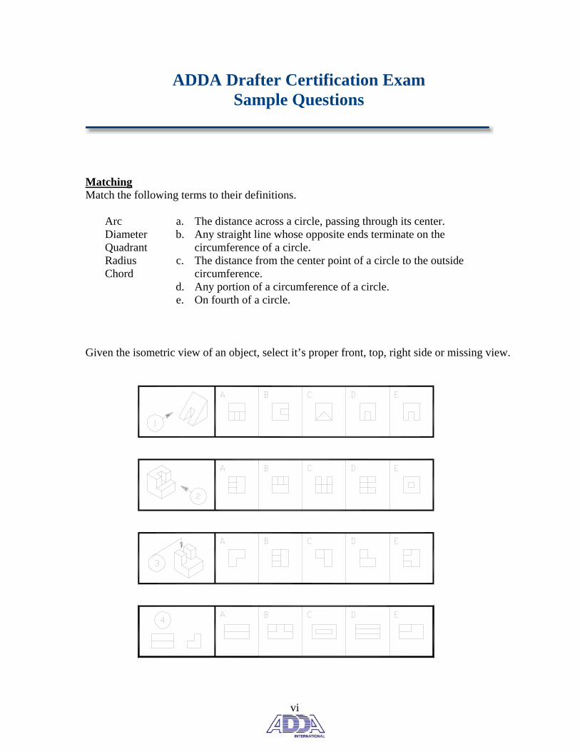
Matching Match the following terms to their definitions. a. The distance across a circle, passing through its center. b. Any straight line whose opposite ends terminate on the
circumference of a circle. c. The distance from the center point of a circle to the outside
circumference. d. Any portion of a circumference of a circle. e. On fourth of a circle.
Arc Diameter Quadrant Radius Chord
Given the isometric view of an object, select it’s proper front, top, right side or missing view.

ADDA Certified Drafter Professional Examination
The following pages will contain the information covered in the ADDA Basic Mechanical Drafter Certification Examination. The information will cover all areas of the examination and it will be necessary to reference other materials and textbooks for the preparation of this examination. Successful Completers of the Examination Process will hold the right to use the ADDA Trademarked Acronym “CD” after your name. Additional Certifications are available through ADDA related to other disciplines and levels of certification. ADDA does not require, but promotes every individual maintain membership with the association where networking and membership discounts can assist you in furthering you Professional Career All Individuals Certified through ADDA and all Members of ADDA are required to abide by the ADDA Code of Ethics. Any violation of the ADDA Code of Ethics can result in the removal and dismissal of an individual’s certification in accordance with the ADDA’s Policies and Constitution & By-Laws

Drafter Certification Exam Components
The function of the ADDA Drafter Certification Examination is to determine entry level drafter knowledge. The computer scored exam is comprised of true or false, multiple choice and matching questions. The exam is a two hour timed exam containing between 340-350 questions. The questions found on the exam fall into ten basic categories. • View Identification (20 percent)
• Dimensioning Standards and Terminology
(19 percent)
• General Drafting Terminology (12 percent)
• Orthographic Projection Standards and Terms (10 percent)
• Section View Standards and Terminology (10 percent)

Drafter Certification Exam Components
• General Drafting Standards (8 percent)
• Manufacturing Processes/Welding (8 percent)
• Pictorial View Standards and Terminology
(6 percent)
• Auxiliary View Standards, Definitions and Terminology (4 percent)
• Computer/CAD Terminology (3 percent) The American Design Drafting Association is now able to provide an exam analysis for schools interested in their student’s areas of strength and weakness. This short report will give the group percentage correct for each of these components of the exam. There is a minimal charge for this service.
View Identification
Visualizing different orthographic views from a pictorial drawing or visualizing a pictorial drawing from orthographic views is a critical skill for drafters. This skill will be tested extensively on this exam. (20 percent of exam)
Samples
• Identify Front Views – Given an isometric view of an object, identify the proper front view from four given possibilities.
• Identify Right Side Views– Given an isometric view of an object, identify the proper right side view from four given possibilities.
• Identify Top Views – Given the isometric view of an
object, identify the proper top view from four given possibilities.
• Identify Missing Views – Given two views of an orthographic drawing, identify the missing third view from four given possibilities.
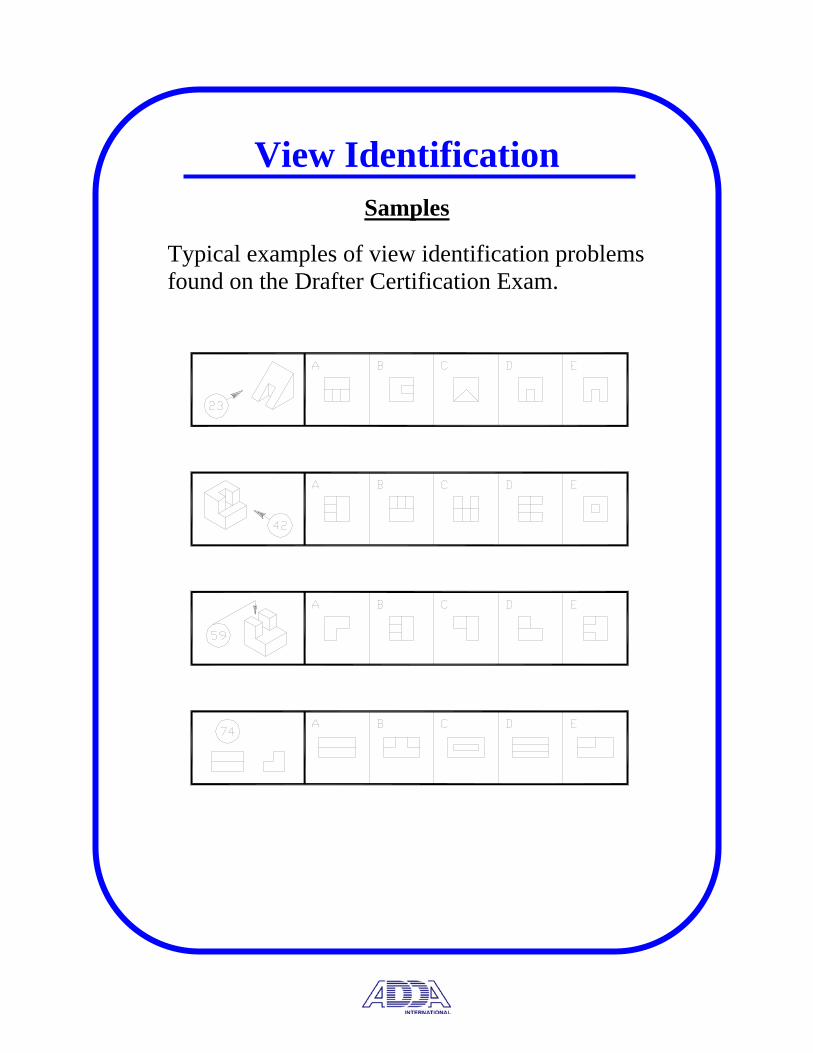
View Identification
Samples
Typical examples of view identification problems found on the Drafter Certification Exam.

Dimensioning Standards and Terminology
Basic lettering rules, dimension types and styles, tolerancing rules and definitions and ASME Y14.5M-1994 dimensioning rules excluding Geometric Dimensioning and Tolerancing interpretation.
Size vs. Location Dimensions
L = LOCATION DIMENSIONS = SIZE DIMENSION
S
L
L
4X Ø (SIZE) EVENLY SPACED (XX)
S
S
S
L S
L
S
S
S
S
L
S

Dimensioning Standards and Terminology
Dimensioning Systems
• Unidirectional – All dimensions read from the bottom of the drawing sheet.
• Aligned – Dimensions aligned with the dimension line.
Dimensions read from the bottom and right side of the drawing sheet.
Dimensioning Geometry
• Review the proper methods of dimensioning arcs, angles, chamfers, counterbores, slots etc.

Total Runout
Circular Runout
Symmetry
Concentricity
Position
Parallelism
Perpindicularity
Angularity
Profile of a Surface
Profile of a Line
Cylindricity
Circularity (roundness)
Flatness
Straightness
Square
Most Material Condition
Least Material Condition
Diameter
Depth
Countersink
Counterbore
Dimensioning Standards and Terminology
Dimensioning practices and Rules based on ASME Y14.5M 1994. Identify geometric symbols but not geometric dimensioning and tolerancing practices.
Dimensioning Standards and Terminology
Standard Terminology
• Actual Size – The size of the part as measured.
• Allowance – The minimum clearance or maximum interference between two mating parts.
• Basic Size - The size from which the limits of size are derived by the application of allowances and tolerance.
• Clearance – The space between two mating parts.
• Feature - A portion of a part, such as a hole, keyway, or flat surface.
• Least Material Condition – The maximum hole diameter or minimum shaft diameter. When a part weighs the least.
• Limits - The maximum and minimum allowable sizes of a feature.
• Maximum Material Condition – The minimum hole diameter or maximum shaft diameter. When the part weighs the most.

Dimensioning Standards and Terminology
Standard Terminology
• Reference Dimension - A non-toleranced dimension used for information purposes only. It may not govern production or inspection.
• Tolerance – The total amount by which the part dimensions are permitted to vary.
• Unilateral Tolerance – Variation of size in one direction either
positive or negative. • Bilateral Tolerance – Variation of size in both directions
positive and negative.
• Specific Tolerance – Stated with dimension in field of drawing.
• General Tolerance – Stated in title block.

• Clearance Fit Tolerance – Internal Dimension maintains a smaller size than external between mating parts. Fit type: RC – Running and Sliding, LC – Locational Clearance
• Interference Fit Tolerance – Internal Dimension maintains a
larger size than external between mating parts. Fit type: LT – Transition
• Transition Fit Tolerance – Condition where a clearance or
interference fit may be present between mating parts. Fit type: LN – Locational Interference, FN – Force or Shrink
• Basic Hole System – Minimum hole size is used as the base size for fit tolerance calculations.
• Basic Shaft System – Maximum shaft size is used as the basic
size for fit tolerance calculations.
Reference the Appendix for
Fits and Allowance Tables

Dimensioning Standards and Terminology
Standard Dimensioning Rules
• Dimensions should be given between features, which have functional relationships.
• Dimensions should be given that control the relationship of mating parts.
• Dimension and extension lines should not cross.
• Dimension lines should not cross each other.
• Cylindrical features should be located by their centerlines.
• Cylindrical features should be located in the circular view.
• Extension lines from dimensions and centerlines should not extend between two views. (auxiliary view ex.)
• Notes should always be lettered horizontally on the drawing sheet.
• A cylindrical feature should be dimensioned with its length and diameter in the rectangular view.
Dimensioning Standards and Terminology
Standard Dimensioning Rules
• Dimensions should be given to finished surfaces if at all possible.
• Dimensions should be kept off the views of the object, if possible, to promote drawing clarity.
• Dimensions applying to adjacent views should be placed between the views.
• Dimensional figures should be .125 (3mm) tall.
• A diameter dimension should be preceded by the ∅ symbol.
• A radius dimension should be preceded by the R symbol.
• Each dimension may appear only one time on a drawing the exception being a reference dimension.
• If possible, dimensions should be given so that the production personnel need not calculate any dimensions.
• Do not scale drawings for production purposes.

Dimensioning Standards and Terminology
Standard Dimensioning Rules
• A dimension on a drawing that is not to scale must be
underlined or denoted either NTS or NOT TO SCALE.
• The first dimension on a view should be placed at least .375” away from the view with subsequent dimensions .250” apart.
• The abbreviation TYP (typical) may be used for non-critical repeated features such as fillets or rounds.
• Dimension should be given on the view where the shape of the feature is shown.
• No line of the drawing may be used for, or coincide with, a dimension line.
• The shoulder of a leader must start at either the beginning or the end of a note with the shoulder mid height of the lettering.
• Utilize only those dimensions that are necessary to produce the part.
• Dimensioning to hidden lines is to be avoided.
• Stagger dimensional figures to avoid crowding and poor drawing legibility.

Dimensioning Standards and Terminology
Standard Dimensioning Rules
• If dimensional figures must appear in a sectioned area, a clear
space should be provided.
• A local note is applied directly to a view of the drawing and supplies manufacturing information.
• A general note applies to the entire drawing.
• Longer dimensions should be placed outside shorter dimensions to avoid crossing dimension and extension lines.
• It is permissible for extension lines to cross extension lines.
• A complete chain of dimensions is to be avoided.
• Finish marks may be omitted it the part is finished all over and a general note or title block note is used.
• Circles should be dimensioned by giving a diameter dimension and arcs by a radius dimension.
• Notes for machining operations should be given in the order they are to be performed.
• All dimensions have a tolerance except those identified as reference, max, min or are commercial stock.

EIGHT EQUAL SIDESEIGHT EQUAL ANGLES
SEVEN EQUAL SIDESSEVEN EQUAL ANGLES
SIX EQUAL SIDESSIX EQUAL ANGLES
FIVE EQUAL SIDESFIVE EQUAL ANGLES
OCTAGONHEPTAGONHEXAGONPENTAGON
NO PARALLELSIDES
TWO PARALLELSIDES
OPPOSITESIDES EQUAL
TRAPEZIUMTRAPEZOIDRHOMBOID
EQUAL SIDESOPPOSITE SIDES EQUALINTERNAL ANGLES 90°
ALL EQUAL SIDES90° INTERNAL ANGLES
RHOMBUSRECTANGLESQUARERIGHT TRIANGLE
RIGHT TRIANGLEONE 90°
INTERIOR ANGLE
OBTUSESCALENETRIANGLE
OBTUSEISOSCELESTRIANGLE
OR ANGLESNO EQUAL SIDES
TRIANGLEACUTE SCALENE
TWO ANGLES EQUALTWO SIDES AND
TRIANGLEISOSCELES
ANGLES EQUALALL SIDES AND
TRIANGLEEQUILATERAL
ACUTE TRIANGLESno interior angle isgreater than 90°
OBTUSE TRIANGLESone angle is
greater than 90°
General Drafting Terminology
The Certification Test contains several questions regarding to geometric terms and shapes including the metric system.
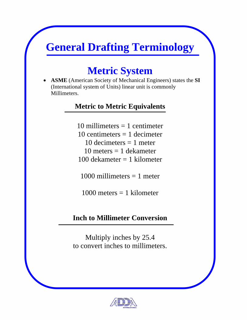
General Drafting Terminology
Metric System • ASME (American Society of Mechanical Engineers) states the SI
(International system of Units) linear unit is commonly Millimeters.
Metric to Metric Equivalents
10 millimeters = 1 centimeter 10 centimeters = 1 decimeter
10 decimeters = 1 meter 10 meters = 1 dekameter
100 dekameter = 1 kilometer
1000 millimeters = 1 meter
1000 meters = 1 kilometer
Inch to Millimeter Conversion
Multiply inches by 25.4 to convert inches to millimeters.

General Drafting Terminology
• Acute Angle - An angle of less than 90°.
• Arc - Any portion of the circumference of a circle.
• Chord - Any straight line whose opposite ends terminate on the
circumference of a circle
• Complementary Angles - Two angles whose sum is 90°.
• Diameter - The distance across a circle passing through its center.
• Equilateral Triangle - A triangle with three equal sides and three
equal angles
• Isosceles Triangle - A triangle with two equal sides and two equal
angles.
• Major axis - The long axis of an ellipse.

General Drafting Terminology
• Minor Axis - The short axis of an ellipse.
• Radius - The distance from the center point of a circle to the outside circumference.
• Obtuse Angle - An angle greater than 90°.
• Right Triangle (angle) - A triangle with one 90° angle.
• Supplementary Angles - Two angles whose sum is 180°.
• Circumscribed - A figure bounding so as to touch in as many places possible.
• Inscribed - A figure encircled so as to touch in as many places possible.
• Perpendicular - At 90° to a given plane or line.
• Symmetrical - A quality in which all the features on either side of a point, line or a plane are identical.
General Drafting Terminology • Fraction - A part of a whole, such as ½ or ¼.
• Half scale - 1:2
• Double Size – 2:1
• Draw to scale - Drawing an object to a set proportion such as ½, ¼ or double its actual size.
• Metric system - A decimal system of weights and measures based on the meter and the kilogram.
• Bevel - A slanted surface not at 90° to another surface.
• Chamfer - A beveled corner at the opening of a hole or the end of a cylindrical part to eliminate sharp edges.
• Fillet - An interior corner found on cast, forged or molded parts.
• Knurl - A diamond shaped or parallel pattern cut into cylindrical surfaced to improve gripping or bonding between parts.

General Drafting Terminology • Round - An exterior corner found on cast, forged or molded parts.
• Parallel Lines – Lines that are equidistant/non-intersecting.
• Skew Lines – Lines that are non-intersecting, non-parallel in 3-D space.
• Quadrilateral - A plane figure bounded by four straight sides.
• Trapezoid - Two sides parallel
• Ellipse – A foreshortened circle having a major and a minor axis.
• Bisect – To divide into two equal parts.
• Quadrant – ¼ of a circle.
• Number of degrees found in a circle (360°), a triangle (180°).
• Number of minutes in a degree (60), seconds in a minute (60).

PROJECTION PLANEFRONTAL PROJECTION PLANE
PROFILE
PROJECTION PLANEHORIZONTAL
WIDTH
DEPTH
HEIGHT
REAR LEFT RIGHT
BOTTOM
FRONT
TOP
Orthographic Projection
Orthographic or multi-view projection is the basic building block of drafting. This section of the test covers terms, definitions and standards, view selection criteria and projection planes.
Projection planes, standard views, basic dimensions
• Front, Top and Right Side Views • Frontal, Horizontal and Profile Projection Planes • Height, Width and Depth
Orthographic Projection
Rule for selecting the number of required views
• Draw only the number of views required to completely describe the object so that it may be manufactured with repeatability. Rules for selecting the proper front view
• Show the part in it’s normal operating position.
• Select the view that shows the part’s most descriptive shape.
• Select the front view to eliminate hidden lines in adjacent views.
• Place the longest dimension of the part in the front view.
• Select the front view that gives the part a stable position on the drawing sheet.
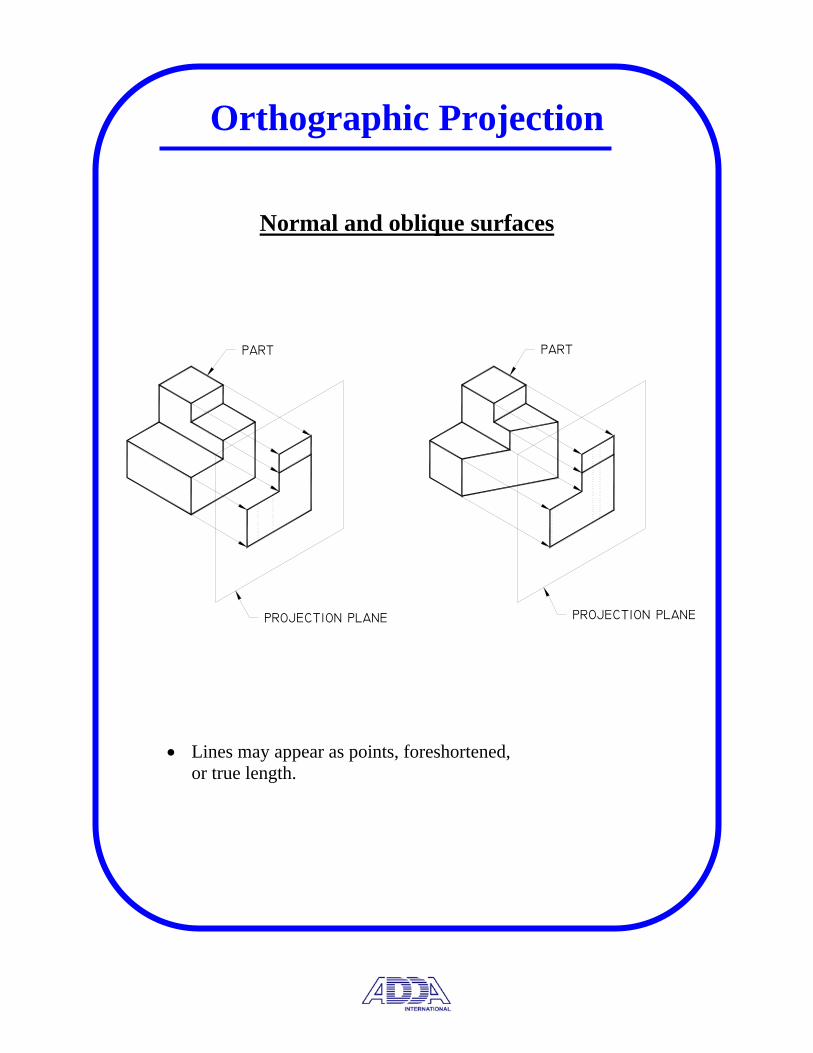
Orthographic Projection
Normal and oblique surfaces
• Lines may appear as points, foreshortened or true length.
• Lines may appear as points, foreshortened, or true length.
PARTPART
PROJECTION PLANEPROJECTION PLANE
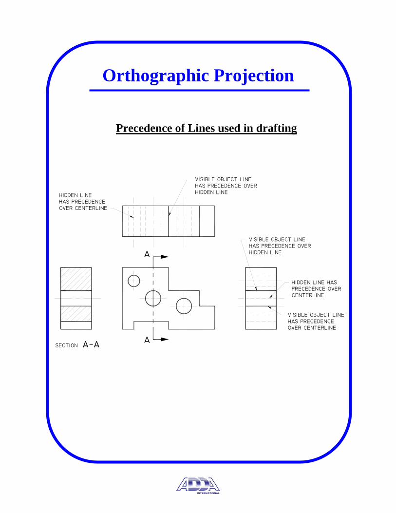
HIDDEN LINEHAS PRECEDENCEOVER CENTERLINE
VISIBLE OBJECT LINEHAS PRECEDENCE OVERHIDDEN LINE
VISIBLE OBJECT LINEHAS PRECEDENCEOVER CENTERLINE
HIDDEN LINE HASPRECEDENCE OVERCENTERLINE
VISIBLE OBJECT LINEHAS PRECEDENCE OVERHIDDEN LINE
SECTION a−a a
a
Orthographic Projection
Precedence of Lines used in drafting
TOP VIEW
SIDE VIEW
FRONT VIEW
third−angle projection
line of sightlin
e of s
ight
line of sight
Orthographic Projection
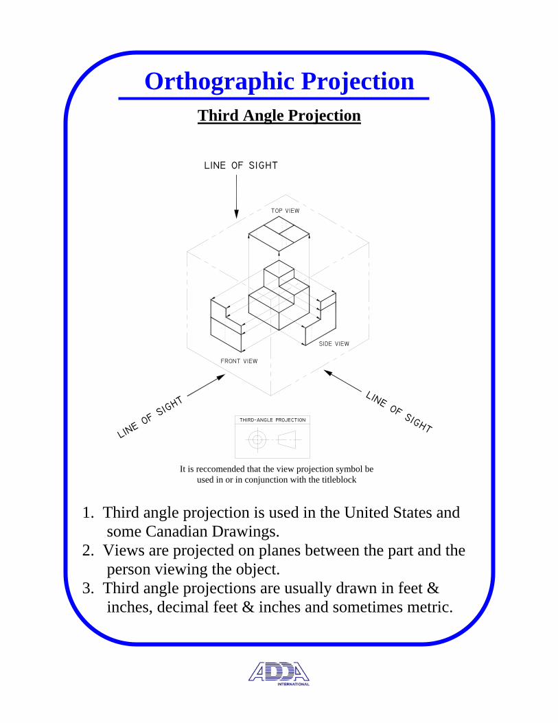
Third Angle Projection
1. Third angle projection is used in the United States and some Canadian Drawings. 2. Views are projected on planes between the part and the person viewing the object. 3. Third angle projections are usually drawn in feet & inches, decimal feet & inches and sometimes metric.
It is reccomended that the view projection symbol be used in or in conjunction with the titleblock

FRONT VIEWSIDE VIEW
TOP VIEW
first−angle projection
line of sightlin
e of s
ight
line of sight
Orthographic Projection
First Angle Projection
1. First angle projection is used outside the United States and most Canadian Drawings. 2. Views are projected on planes behind the part. 3. First angle projections are usually drawn in metric.
It is reccomended that the view projection symbol be used in or in conjunction with the titleblock

Section View Standards and Terms
The section view portion of the test evaluates knowledge of terminology and standards, view applications and rules, and section view types.
What is the function of a section view?
• To show complicated interiors of parts that are difficult to interpret through the use of hidden lines.
Some Basic Rules
• Visible edges and contours behind the cutting plane should be shown.
• Hidden lines are generally omitted on a sectioned view. Explain the function of the cutting plane line and it’s application for the different section view types.
• To indicate the location of the imaginary cut made to reveal interior details.
• Identify the line of sight for the individual view in the part through the use of arrows.
• If 2 or more sections are present; identify the particular sections through the use of letter identifiers.

Section View Standards and Terms
Explain the application of section lines and their forms.
• Cast iron, .125” uniformly spaced thin lines, is the general-purpose section line.
• Section lines should all be at the same angle for a single part. Section lines at different angles on the same drawing indicate more than one part.
• Section lines should not be drawn vertical, horizontal or parallel to an adjacent object line of the drawing.
• Section lines can identify the general class of material such as steel, brass or rubber.
• Thin items such as gaskets or sheet metal are shown unsectioned.
Types of features that are unsectioned.
• On an assembly section, items that are not sectioned
include; shafts, bolts, nuts, rods, rivets, keys, pins, screws, gear teeth, spokes, etc.

Section View Standards and Terms
Identify and describe the application of the following section view types.
Full Section
The cutting plane line extends straight though the object, generally at the centerline of symmetry.
LINE O
F SIGH
T
SECTION a−a
a a

Section View Standards and Terms
Half Section
The cutting plane passes half way through the object, removing one fourth of the object.
• Half sections are most applicable to symmetrical objects to show both the interior and exterior in a single view.
• A centerline is used between the sectioned and the unsectioned half.
• Frequently used for assembly drawings.
centerline used between
sectioned and unsectioned halves.
unsectioned halfhidden lines onlyused for drawingclarity.
sectioned halfto have no hidden lines.

A−ASECTION
AA
LINES ARE NOT SHOWN ON THE SECTIONED VIEWWHERE THE OFFSETS APPEAR IN THE SECTION LINE.
Section View Standards and Terms
Offset Section To include features that do not appear in a straight line, the cutting plane may be offset to pass through the features. Offsets or bends created by the cutting plane are not shown on the section view.
A
A
SECTION A−A
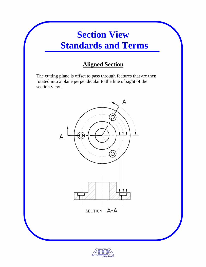
Section View Standards and Terms
Aligned Section The cutting plane is offset to pass through features that are then rotated into a plane perpendicular to the line of sight of the section view.
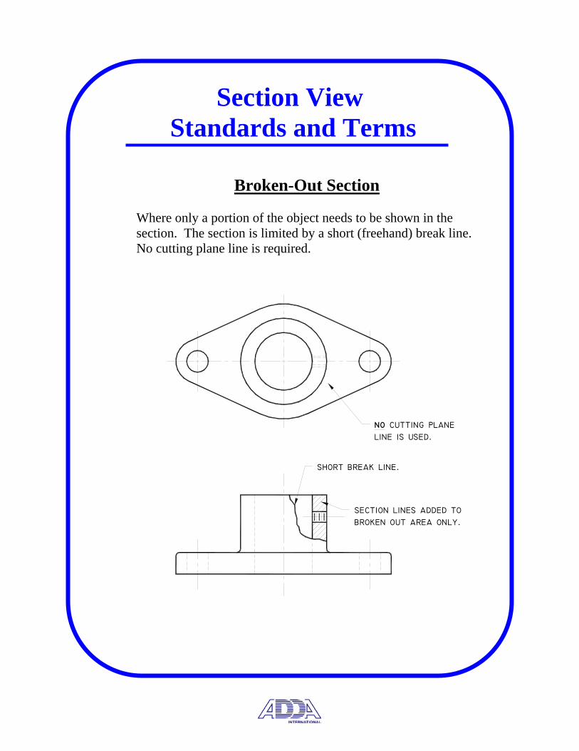
section lines added tobroken out area only.
short break line.
no cutting planeline is used.
Section View Standards and Terms
Broken-Out Section
Where only a portion of the object needs to be shown in the section. The section is limited by a short (freehand) break line. No cutting plane line is required.

Section View Standards and Terms
Revolved Section A cutting plane line is passed through the object and revolved 90° in place towards the plane of the drawing. Used to show the cross section of a spoke, bar, rib, etc.

Section View Standards and Terms
Removed Section A section that is not a direct projection from the view with the cutting plane. The section view is generally moved from its normal projection position, but must remain in its true orthographic orientation.
• Removed sections are often drawn at a scale different from the view it was taken from.
• Center lines may extend from the imaginary cutting plane to the removed section provided it is symmetrical.
SECTION C−CSECTION B−BSECTION A−A
C
C
B
B
A
A
Section View Standards and Terms
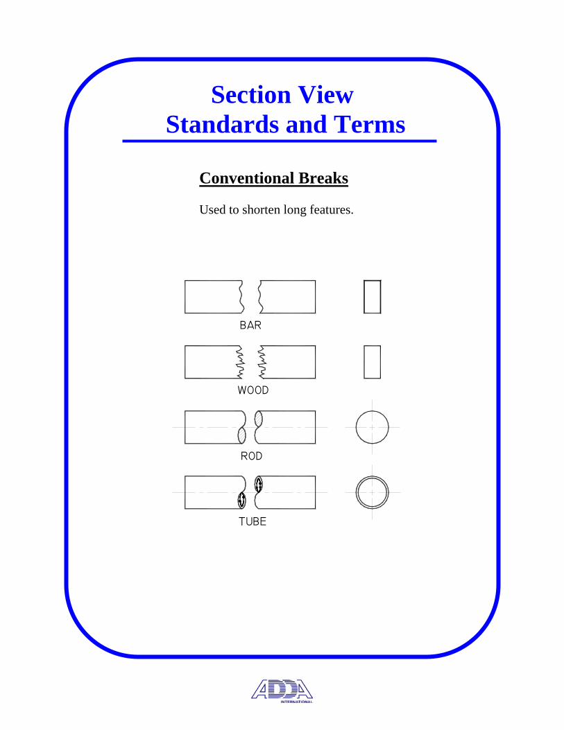
Conventional Breaks
Used to shorten long features.
TUBE
ROD
WOOD
BAR

Section View Standards and Terms
Ribs/Web/Keyways
Webs, ribs, gear teeth and other like features are not sectioned to avoid giving a false impression of the parts thickness.
RIBS LEFTUNSECTIONED
A
A
A
A
A
A
SECTION A−A
SECTION A−ASECTION A−A
KEYWAY LEFTUNSECTIONED
SPOKES LEFTUNSECTIONED
CONVENTIONALPRACTICE
TRUEPROJECTION
SECTION A−ASECTION A−ACONVENTIONALPRACTICE
TRUEPROJECTION
CONVENTIONALPRACTICE
General Drafting Standards
This portion of the Certification Test examines knowledge of terms and definitions regarding detail drawings, assembly drawings and the line types used in drafting.
Define and describe the components that make up a detail drawing.
• Necessary multiviews • Dimensional information • Identify part/part number • Part material • Engineering changes (Revision Block) • Drafter/checker names • Assembly the part fits/quantity required • General notes with manufacturing information
Define and describe the components that make up an assembly drawing.
• Arrangement of parts • Sections required to show internal features • Enlarged views to show detail • Parts list/bill of materials • Reference item numbers keyed to BOM • Manufacturing processes required during assembly
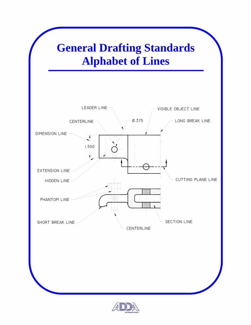
General Drafting Standards Alphabet of Lines
Ø.375 LONG BREAK LINE
CUTTING PLANE LINE
1.500
LEADER LINE
DIMENSION LINE
EXTENSION LINE
HIDDEN LINE
VISIBLE OBJECT LINE
PHANTOM LINE
SHORT BREAK LINE SECTION LINE
CENTERLINE
CENTERLINE
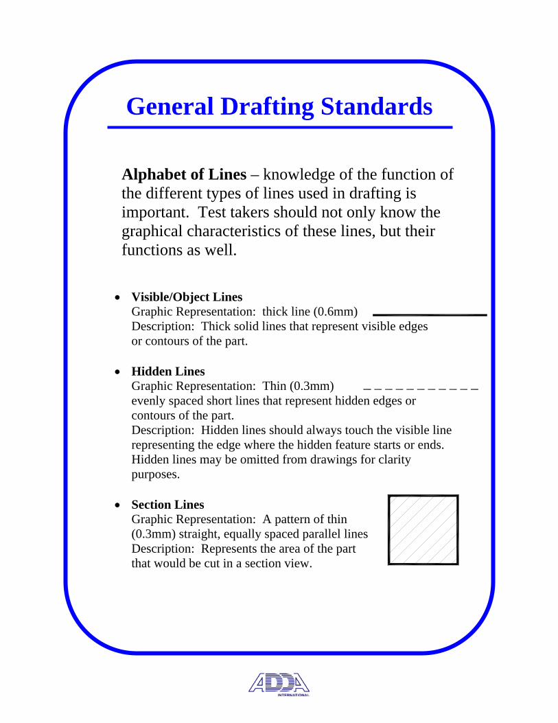
General Drafting Standards
Alphabet of Lines – knowledge of the function of the different types of lines used in drafting is important. Test takers should not only know the graphical characteristics of these lines, but their functions as well.
• Visible/Object Lines Graphic Representation: thick line (0.6mm) Description: Thick solid lines that represent visible edges or contours of the part.
• Hidden Lines Graphic Representation: Thin (0.3mm) evenly spaced short lines that represent hidden edges or contours of the part. Description: Hidden lines should always touch the visible line representing the edge where the hidden feature starts or ends. Hidden lines may be omitted from drawings for clarity purposes.
• Section Lines Graphic Representation: A pattern of thin (0.3mm) straight, equally spaced parallel lines Description: Represents the area of the part that would be cut in a section view.

EXTENSION LINE
4.00
DIMENSION LINE
General Drafting Standards
• Centerlines Graphic Representation: Thin lines (0.3mm) consisting of alternate long and short dashes. Centerlines form a cross (3mm) in the center of circles and should extend (8mm) outside the feature Description: Represent the centers of circles or arcs, an axis of symmetry or a path of motion.
• Symmetry Line Graphic Representation: Thick lines (0.6mm) geometrically the same as a centerline with the addition of two short thick parallel lines at each end of the line. Description: Used as an axis of symmetry for a partial view.
• Dimension Line Graphic Representation: Thin lines (0.3mm) terminated with uniformly sized arrowheads. Description: Dimension lines are used to indicate the extent and direction of the dimension.
• Extension Line Graphic Representation: Thin lines (0.3mm) spaced 1.5mm away from the feature being dimensioned and 3mm past the arrowhead of the dimension. Description: Used to indicate the point or line to which the dimension applies.
General Drafting Standards
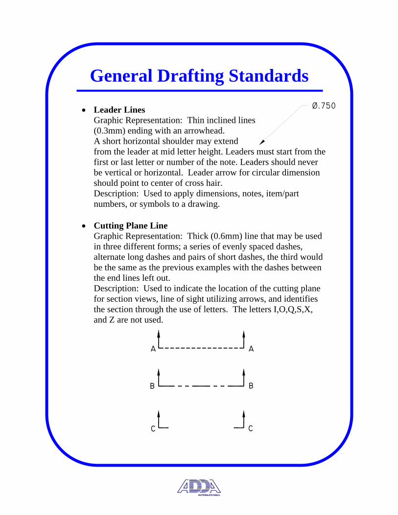
• Leader Lines Graphic Representation: Thin inclined lines (0.3mm) ending with an arrowhead. A short horizontal shoulder may extend from the leader at mid letter height. Leaders must start from the first or last letter or number of the note. Leaders should never be vertical or horizontal. Leader arrow for circular dimension should point to center of cross hair. Description: Used to apply dimensions, notes, item/part numbers, or symbols to a drawing.
• Cutting Plane Line Graphic Representation: Thick (0.6mm) line that may be used in three different forms; a series of evenly spaced dashes, alternate long dashes and pairs of short dashes, the third would be the same as the previous examples with the dashes between the end lines left out. Description: Used to indicate the location of the cutting plane for section views, line of sight utilizing arrows, and identifies the section through the use of letters. The letters I,O,Q,S,X, and Z are not used.
Ø.750
cc
bb
aa
General Drafting Standards
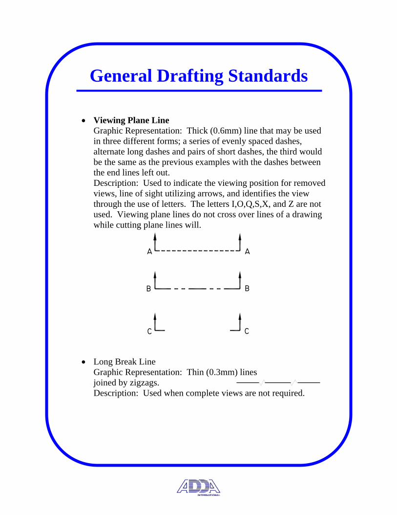
• Viewing Plane Line Graphic Representation: Thick (0.6mm) line that may be used in three different forms; a series of evenly spaced dashes, alternate long dashes and pairs of short dashes, the third would be the same as the previous examples with the dashes between the end lines left out. Description: Used to indicate the viewing position for removed views, line of sight utilizing arrows, and identifies the view through the use of letters. The letters I,O,Q,S,X, and Z are not used. Viewing plane lines do not cross over lines of a drawing while cutting plane lines will.
• Long Break Line Graphic Representation: Thin (0.3mm) lines joined by zigzags. Description: Used when complete views are not required.
cc
bb
aa

General Drafting Standards
• Short Break Line Graphic Representation: Thick (0.6mm) freehand line. Description: Used when complete views are not required.
• Phantom Line Graphic Representation: Thin (0.3mm) line comprised of alternate long dashes and pairs of short dashes. Description: Used to show alternate position of moving parts, repeated details, adjacent positions of related parts and filleted or rounded corners.
• Stitch Line Graphic Representation: Thin (0.3mm) lines in two forms; dots of 0.3mm spaced 0.3mm apart or short dashes and spaces of equal length. Description: Used to indicate a sewing or stitching process.
• Chain Line Graphic Representation: Thick (0.6mm) line consisting of alternate long and short dashes. Description: Used to indicate a surface to receive additional treatment or a projected tolerance zone identified through the use of geometric dimensioning and tolerancing.

Manufacturing Processes Hole Terminology
This section of the test covers hole making terminology, finish mark applications and welding symbols.
Hole Making Terminology
• Bore – To enlarge a hole to a more accurate size.
• Blind Hole – A hole that does not go all the way through the part.
• Counterbore – The enlargement of the end of a hole to a specified diameter and depth.
• Counterdrill – To form a conical shoulder in a drilled hole by enlarging it with a larger drill.
• Countersink – To recess a hole with a cone shaped tool to provide a seat for a flat head screw.
• Drill – A tool with a conical point used to machine holes in a part.
• Ream – To enlarge a hole to a more accurate size and surface finish.
• Tap – A tool used to cut internal threads. (Tap Drill chart – Appendix A31- A35)

• Threaded Fasteners Terminology • Form – Profile of a thread, such as simplified, detailed or
schematic. Simplified form is industry preferred and quickest to execute.
• Crest – The edge or surface that joins the side of a thread and is furthest from the cylinder or cone; the outside point of a thread.
• Root – The edge or surface the joins the side of adjacent thread forms and coincides with the cylinder or cone; the inside meeting point of a thread.
• Pitch – The distance between corresponding points on adjacent thread forms measured parallel to the axis; distance between thread points.
• Lead - The distance a thread part moves axially; one complete revolution of a thread.
(American National Standard Unified Screw Thread Table – Appendix A36) • Other Fasteners Terminology • Key – Piece of metal placed so that part of it lies in a groove
cut in a shaft, but fitting into a groove cut into a mating hub. Creating restrictive movement between mating parts.
• Rivet – Used as a permanent fastener, generally between pieces of sheet or rolled metal.
• Spring – A coiled elastic body designed to store energy when deflected.
• Retaining Ring – designed to prevent axial movement of a shaft in a hub; generally a ring is placed around shaft to restrict movement within the mating part (hub).

Manufacturing Processes Finish Marks
Finish Marks
• Surface finish relates to the waviness, roughness, lay and flaws of a parts surface.
• Surface finish refers to the smoothness of the finished surface created by machining, honing, grinding or lapping.
• Finish marks should be placed on the edge view of finished surfaces.
• For parts finished all over, marks may be omitted and covered with a general note.
• Finish marks are left off rolled stock, plate, sheet or other raw materials not machined in the manufacturing process.
X
Manufacturing Processes Welding
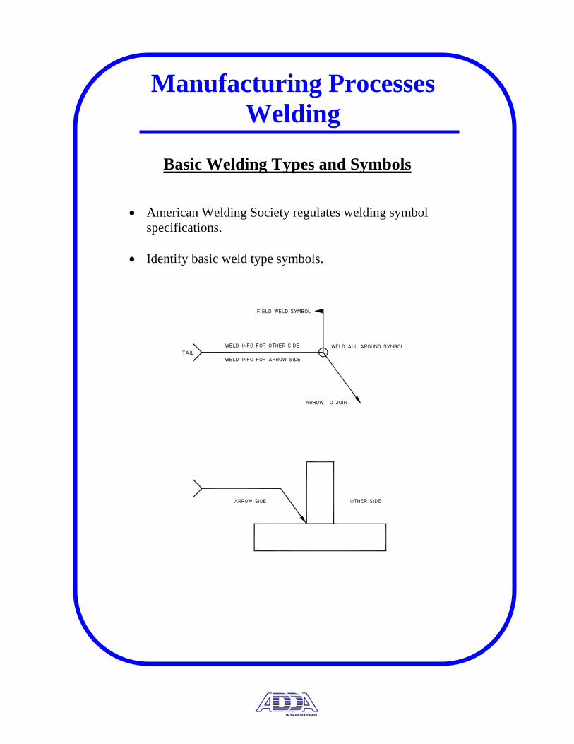
Basic Welding Types and Symbols
• American Welding Society regulates welding symbol
specifications. • Identify basic weld type symbols.
other sidearrow side
arrow to joint
weld all around symbol
field weld symbol
tailweld info for arrow side
weld info for other side

1/4 X 1/2
1/4
1/4
1/4
1/4
Manufacturing Processes Welding
Fillet Welds
A fillet weld is used to make lap joints, corner joints, and T joints. The fillet weld is roughly triangular in cross-section, although its shape is not always a right triangle or an isosceles triangle.
Manufacturing Processes Welding
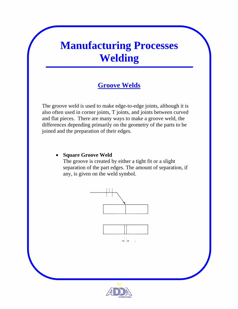
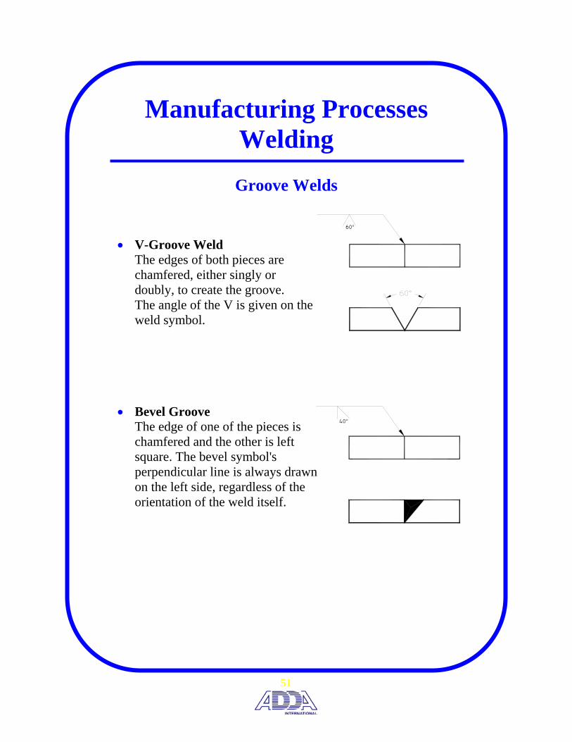
Groove Welds
The groove weld is used to make edge-to-edge joints, although it is also often used in corner joints, T joints, and joints between curved and flat pieces. There are many ways to make a groove weld, the differences depending primarily on the geometry of the parts to be joined and the preparation of their edges.
• Square Groove Weld The groove is created by either a tight fit or a slight separation of the part edges. The amount of separation, if any, is given on the weld symbol.
14
50
60°
40°
Manufacturing Processes Welding
Groove Welds
• V-Groove Weld The edges of both pieces are chamfered, either singly or doubly, to create the groove. The angle of the V is given on the weld symbol.
• Bevel Groove The edge of one of the pieces is chamfered and the other is left square. The bevel symbol's perpendicular line is always drawn on the left side, regardless of the orientation of the weld itself.
51
Manufacturing Processes Welding
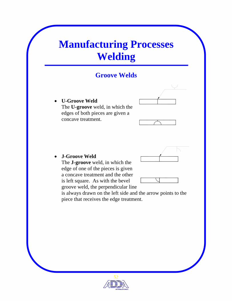
Groove Welds
• U-Groove Weld The U-groove weld, in which the edges of both pieces are given a concave treatment.
• J-Groove Weld The J-groove weld, in which the edge of one of the pieces is given a concave treatment and the other is left square. As with the bevel groove weld, the perpendicular line is always drawn on the left side and the arrow points to the piece that receives the edge treatment.
52

Manufacturing Processes Welding
Other Welds
• Plug or Slot Weld Plug welds and slot welds are used join overlapping members, one of which has holes (round for plug welds, elongated for slot welds) in it. Weld metal is deposited in the holes and penetrates and fuses with the base metal of the two members to form the joint.
plug weld
7/8 3(3)
3.0
3.0
78
slot weld
3 12−51
3 1/2
1
5
5/8
(2)
53

seam weld
RSW
spot weld
Manufacturing Processes Welding
Resistance Welding
• Spot Weld Spot welding is the most commonly used type of resistance welding. The material to be joined is placed between two electrodes and pressure is applied. A charge of electricity is then sent from one electrode through the material to the other electrode. Spot welding is especially useful in fabricating sheet metal parts.
• Seam Welding Seam welding is like spot welding except that the spots overlap each other, making a continuous weld seam. In this process, the metal pieces pass between roller electrodes. As the electrodes revolve, the current is automatically turned off and on at the speed at which the parts are set to move.
54
Pictorial Standards and Terms
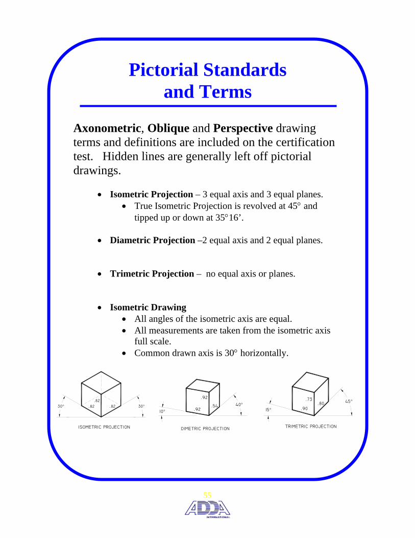
Axonometric, Oblique and Perspective drawing terms and definitions are included on the certification test. Hidden lines are generally left off pictorial drawings.
• Isometric Projection – 3 equal axis and 3 equal planes. • True Isometric Projection is revolved at 45° and
tipped up or down at 35°16’.
• Diametric Projection –2 equal axis and 2 equal planes.
• Trimetric Projection – no equal axis or planes.
• Isometric Drawing • All angles of the isometric axis are equal. • All measurements are taken from the isometric axis
full scale. • Common drawn axis is 30° horizontally.
DIMETRIC PROJECTION
.92
.92
.5410°
40°
TRIMETRIC PROJECTION
.73.80
.9015°
45°
ISOMETRIC PROJECTION
.82
.82
.8230° 30°
55

30°MIN
60°MAX
(HEIGHT, WIDTH & DEPTH)
THE FRONT VIEW APPEARS THE SAMEAS AN ORTHOGRAPHIC PROJECTION
FULL SCALE
Pictorial Standards and Terms
Oblique Drawing
The object is placed with its principal face parallel to the plane of projection. • General Oblique - depth dimension at any scale.
• Cavalier Oblique – depth dimension full scale.
• Cabinet Oblique – depth dimension half scale.
30°MIN
(WIDTH & HEIGHT)
(DEPTH)HALF SCALE
THE FRONT VIEW APPEARS THE SAMEAS AN ORTHOGRAPHIC PROJECTION
FULL SCALE
60°MAX
30°MIN
(WIDTH & HEIGHT)
(DEPTH)ANY SCALE
THE FRONT VIEW APPEARS THE SAMEAS AN ORTHOGRAPHIC PROJECTION
FULL SCALE
60°MAX
56
PERSPECTIVETWO POINT
L.V.P. R.V.P.
HORIZON LINE
PERSPECTIVETHREE POINT
V.P.
L.V.P. R.V.P.
HORIZON LINE
Pictorial Standards and Terms
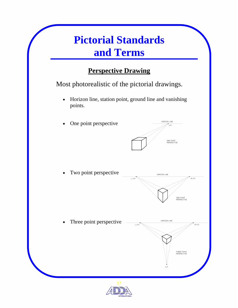
Perspective Drawing
Most photorealistic of the pictorial drawings.
• Horizon line, station point, ground line and vanishing points.
• One point perspective
• Two point perspective
• Three point perspective
PERSPECTIVEONE POINT
V.P.
HORIZON LINE
57

A
A
A
A
TRUE SIZE AND SHAPE SURFACE
Auxiliary View Standards and Terminology
This portion of the test is concerned with auxiliary view terms, standards, methods of construction and types of auxiliary views.
Use and function of an auxiliary view
• To show the true size and shape of a surface that is not parallel to any of the six principal views.
• To show irregularly shaped features that are not adequately shown in the principle views.
• To find the true length of a line. • To find a point view of a line. • To find the true size of a plane. • To find the edge view of a plane. • Circular features on incline surface will appear as an
ellipse in principle view.
58
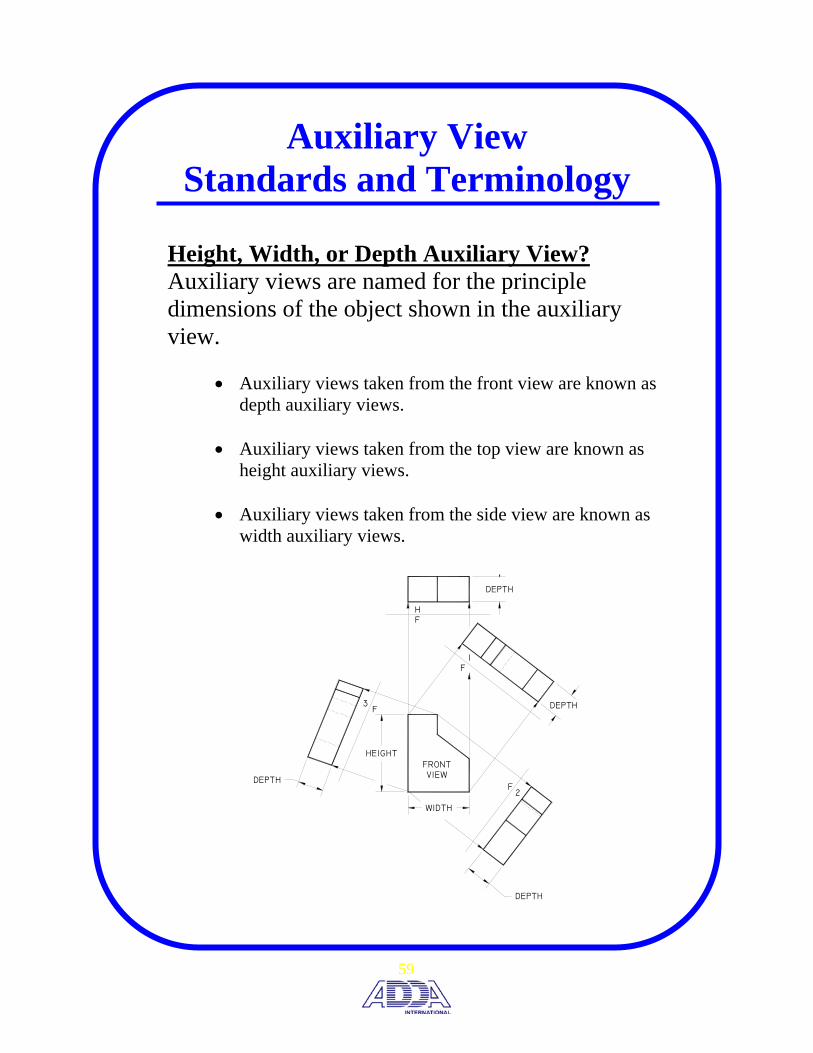
Auxiliary View Standards and Terminology
Height, Width, or Depth Auxiliary View? Auxiliary views are named for the principle dimensions of the object shown in the auxiliary view.
• Auxiliary views taken from the front view are known as depth auxiliary views.
• Auxiliary views taken from the top view are known as height auxiliary views.
• Auxiliary views taken from the side view are known as width auxiliary views.
VIEWFRONT
DEPTH
F3
F2
F1
FH
WIDTH
HEIGHT
DEPTH
DEPTH
DEPTH
59

A
A
A
FOLD LINE
PARALLELPF
A
F1
FH
A
A
A
REFERENCELINE
PARALLELA
Auxiliary View Standards and Terminology
Reference Line/Plane construction method
Fold Line construction method
• The reference line/plane or fold line must be constructed parallel to the edge view of a surface to get the true size and shape of the surface.
60

Auxiliary View Standards and Terminology
Secondary Auxiliary Views
• When a feature of an object is in an oblique position in
relationship to the principal planes of projection, a secondary auxiliary view is required to find the true size and shape of the feature.
TRUE SIZE ANDSHAPE SURFACE
VIEWAUXILIARYSECONDARY
VIEWAUXILIARYPRIMARY
a
a
a
61

Computer/CAD Terminology There are a minimal number of questions relating to computers and CAD software. Questions are general knowledge and non-software specific.
• Must have three components; hardware, software and a user.
• Function of basic computer hardware such as the various input and output devices, graphics card, memory and storage.
• Basic good practices like backing up work frequently.
• File management and size. Bytes vs. megabytes.
• Difference between drafting and design software. A parametric design software will better capture design intent as compared to a two-dimension software package.
62


APPENDIX The following tables, charts, and pages are for reference to drafting and design at the level of this Certification Review. This information is also provided to be a reference to the drafter after completion of the certification process. Some information contained within the appendix was acquired from outside sources, used with permission.


MECHANICAL ABBREVIATIONS


A1
Abbreviations for Mechanical Drawings
If you use abbreviations, you should follow these rules:
1. Use upper case lettering, without periods 2. Do not use spaces within an abbreviation 3. Use same abbreviations for singular or plural
A ACRFLT: Across Flats
ANSI: American National Standards Institute
ANLR: Angular
APPROX: Approximate
ASME: American Society of Mechanical Engineers
ASSY: Assembly
B
BSC: Basic
B/M: Bill of Material
BC: Bolt Circle
BR: Brass
BUSH: Bushing
C
CS: Carbon Steel
CSTG: Casting
CHAM: Chamfer
CIR: Circularity
CRS: Cold-Rolled Steel

A2
Abbreviations for Mechanical Drawings
CONC: Concentric
CBORE: Counterbore
CDRILL: Counterdrill
CSK: Countersink
cm: centimeter
cm2: Square Centimeter
cm3: Cubic Centimeter
D
DEG or °: Degree or Angle
DP: Depth
DIA: Diameter
DIM: Dimension
DWG: Drawing
E EQL SP: Equal Spaced
F
FIG: Figure
FAO: Finish All Over
FL: Flat
A3
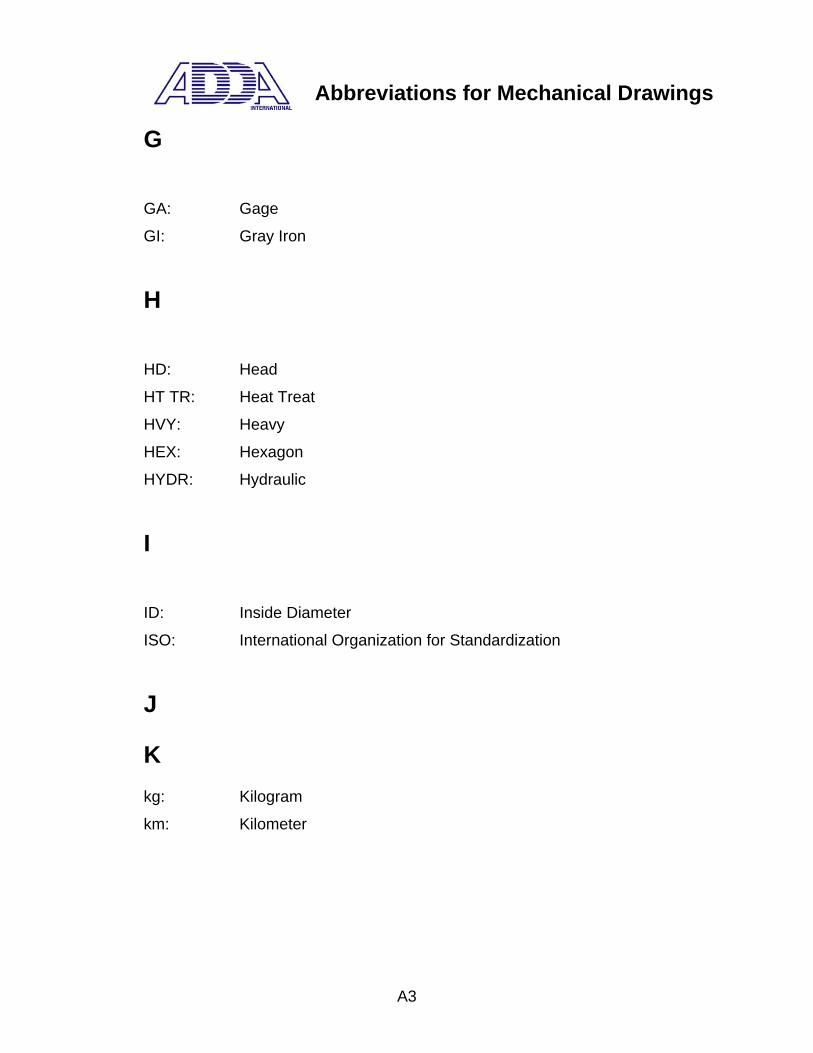
Abbreviations for Mechanical Drawings
G
GA: Gage
GI: Gray Iron
H
HD: Head
HT TR: Heat Treat
HVY: Heavy
HEX: Hexagon
HYDR: Hydraulic
I
ID: Inside Diameter
ISO: International Organization for Standardization
J
K kg: Kilogram
km: Kilometer

A4
Abbreviations for Mechanical Drawings
L
LMC: Least Material Condition
LH: Left Hand
LG: Length
L: Liter
M MST: Machine Steel
MI: Malleable Iron
MATL: Material
MAX: Maximum
MMC: Maximum Material Condition
m: Meter
m2: Square meter
m3: Cubic Meter
M: Metric Thread
μm: Micrometer
mm: Millimeter
MIN: Minimum
‘: Minute (ARC)
MDL: Module
N
NOM: Nominal
NO: Number

A5
Abbreviations for Mechanical Drawings
O OC: On Center
OD: Outside Diameter
P
PAR: Parallel
PERP: Perpendicular
P: Pitch
PC: Pitch Circle
PD: Pitch Diameter
PL: Plate
Q
R R: Radius
REF or ( ): Reference or Reference Dimension
rev/min: Revolutions per Minute
RH: Right Hand
S “: Second (ARC)
SEC: Second (TIME)
SECT: Section
SLOT: Slotted
SOCK: Socket
SPHER: Spherical

A6
Abbreviations for Mechanical Drawings
S∅: Spherical Diameter
SR: Spherical Radius
SFACE: Spotface
SQ: Square
STL: Steel
STR: Straight
SYM: Symmetrical
T NPT: Taper Pipe Thread
THRU: Through
TOL: Tolerance
U
V
W W: Watt
WI: Wrought Iron
WS: Wrought Steel
X
Y
Z
Conversion & Equivalence Tables

REFERENCE TABLES
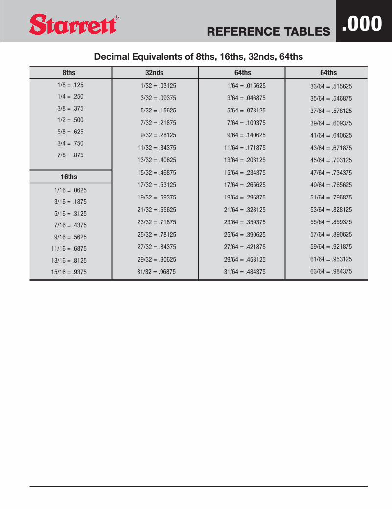
8ths
1/8 = .125
1/4 = .250
3/8 = .375
1/2 = .500
5/8 = .625
3/4 = .750
7/8 = .875
16ths
1/16 = .0625
3/16 = .1875
5/16 = .3125
7/16 = .4375
9/16 = .5625
11/16 = .6875
13/16 = .8125
15/16 = .9375
32nds
1/32 = .03125
3/32 = .09375
5/32 = .15625
7/32 = .21875
9/32 = .28125
11/32 = .34375
13/32 = .40625
15/32 = .46875
17/32 = .53125
19/32 = .59375
21/32 = .65625
23/32 = .71875
25/32 = .78125
27/32 = .84375
29/32 = .90625
31/32 = .96875
64ths
1/64 = .015625
3/64 = .046875
5/64 = .078125
7/64 = .109375
9/64 = .140625
11/64 = .171875
13/64 = .203125
15/64 = .234375
17/64 = .265625
19/64 = .296875
21/64 = .328125
23/64 = .359375
25/64 = .390625
27/64 = .421875
29/64 = .453125
31/64 = .484375
64ths
33/64 = .515625
35/64 = .546875
37/64 = .578125
39/64 = .609375
41/64 = .640625
43/64 = .671875
45/64 = .703125
47/64 = .734375
49/64 = .765625
51/64 = .796875
53/64 = .828125
55/64 = .859375
57/64 = .890625
59/64 = .921875
61/64 = .953125
63/64 = .984375
Decimal Equivalents of 8ths, 16ths, 32nds, 64ths
.000

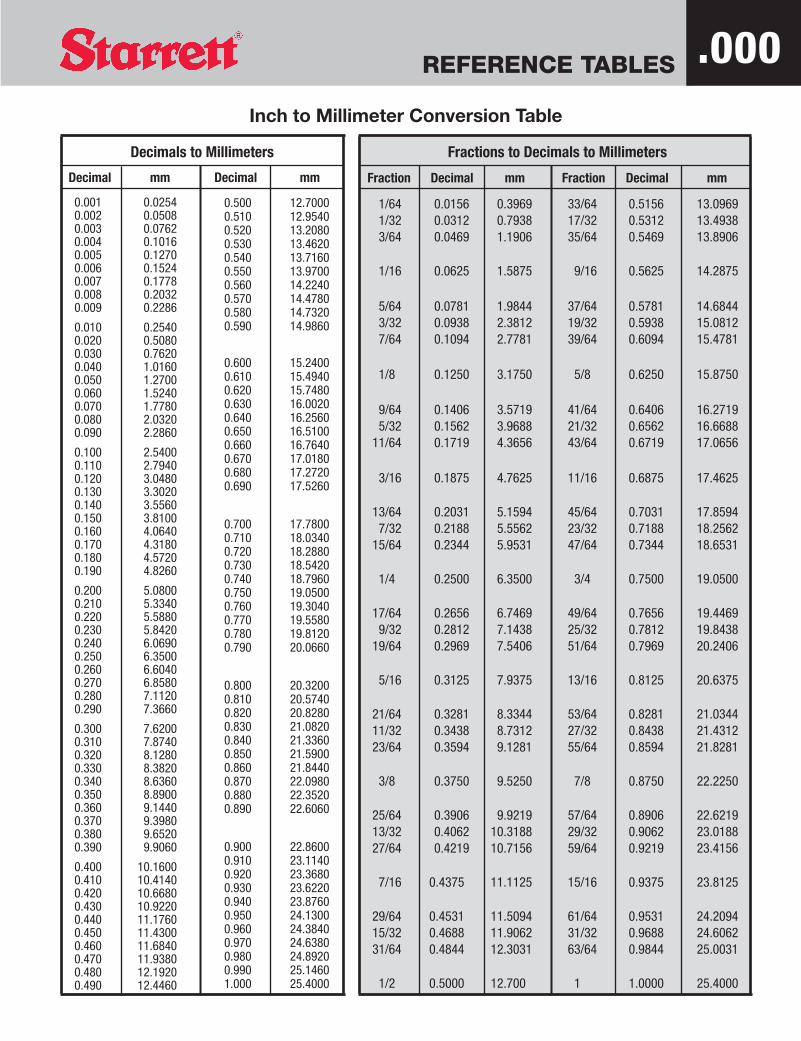
Inch to Millimeter Conversion Table
REFERENCE TABLES
Decimal mm
0.001 0.02540.002 0.05080.003 0.07620.004 0.10160.005 0.12700.006 0.15240.007 0.17780.008 0.20320.009 0.2286
0.010 0.25400.020 0.50800.030 0.76200.040 1.01600.050 1.27000.060 1.52400.070 1.77800.080 2.03200.090 2.2860
0.100 2.54000.110 2.79400.120 3.04800.130 3.30200.140 3.55600.150 3.81000.160 4.06400.170 4.31800.180 4.57200.190 4.8260
0.200 5.08000.210 5.33400.220 5.58800.230 5.84200.240 6.06900.250 6.35000.260 6.60400.270 6.85800.280 7.11200.290 7.3660
0.300 7.62000.310 7.87400.320 8.12800.330 8.38200.340 8.63600.350 8.89000.360 9.14400.370 9.39800.380 9.65200.390 9.9060
0.400 10.16000.410 10.41400.420 10.66800.430 10.92200.440 11.17600.450 11.43000.460 11.68400.470 11.93800.480 12.19200.490 12.4460
Decimal mm
0.500 12.70000.510 12.95400.520 13.20800.530 13.46200.540 13.71600.550 13.97000.560 14.22400.570 14.47800.580 14.73200.590 14.9860
0.600 15.24000.610 15.49400.620 15.74800.630 16.00200.640 16.25600.650 16.51000.660 16.76400.670 17.01800.680 17.27200.690 17.5260
0.700 17.78000.710 18.03400.720 18.28800.730 18.54200.740 18.79600.750 19.05000.760 19.30400.770 19.55800.780 19.81200.790 20.0660
0.800 20.32000.810 20.57400.820 20.82800.830 21.08200.840 21.33600.850 21.59000.860 21.84400.870 22.09800.880 22.35200.890 22.6060
0.900 22.86000.910 23.11400.920 23.36800.930 23.62200.940 23.87600.950 24.13000.960 24.38400.970 24.63800.980 24.89200.990 25.14601.000 25.4000
Fractions to Decimals to Millimeters
Fraction Decimal mm Fraction Decimal mm
1/64 0.0156 0.3969 33/64 0.5156 13.09691/32 0.0312 0.7938 17/32 0.5312 13.49383/64 0.0469 1.1906 35/64 0.5469 13.8906
1/16 0.0625 1.5875 9/16 0.5625 14.2875
5/64 0.0781 1.9844 37/64 0.5781 14.68443/32 0.0938 2.3812 19/32 0.5938 15.08127/64 0.1094 2.7781 39/64 0.6094 15.4781
1/8 0.1250 3.1750 5/8 0.6250 15.8750
9/64 0.1406 3.5719 41/64 0.6406 16.27195/32 0.1562 3.9688 21/32 0.6562 16.6688
11/64 0.1719 4.3656 43/64 0.6719 17.0656
3/16 0.1875 4.7625 11/16 0.6875 17.4625
13/64 0.2031 5.1594 45/64 0.7031 17.85947/32 0.2188 5.5562 23/32 0.7188 18.2562
15/64 0.2344 5.9531 47/64 0.7344 18.6531
1/4 0.2500 6.3500 3/4 0.7500 19.0500
17/64 0.2656 6.7469 49/64 0.7656 19.44699/32 0.2812 7.1438 25/32 0.7812 19.8438
19/64 0.2969 7.5406 51/64 0.7969 20.2406
5/16 0.3125 7.9375 13/16 0.8125 20.6375
21/64 0.3281 8.3344 53/64 0.8281 21.034411/32 0.3438 8.7312 27/32 0.8438 21.431223/64 0.3594 9.1281 55/64 0.8594 21.8281
3/8 0.3750 9.5250 7/8 0.8750 22.2250
25/64 0.3906 9.9219 57/64 0.8906 22.621913/32 0.4062 10.3188 29/32 0.9062 23.018827/64 0.4219 10.7156 59/64 0.9219 23.4156
7/16 0.4375 11.1125 15/16 0.9375 23.8125
29/64 0.4531 11.5094 61/64 0.9531 24.209415/32 0.4688 11.9062 31/32 0.9688 24.606231/64 0.4844 12.3031 63/64 0.9844 25.0031
1/2 0.5000 12.700 1 1.0000 25.4000
Decimals to Millimeters
.000

REFERENCE TABLES
Metric and Inch Equivalents
Linear MeasureMetric Inch
1 millimeter = 0.03937 inch1 inch = { 25.4 millimeters
1 centimeter = 0.3937 inch 2.54 centimeters39.37 inches
1 foot = { 304.8 millimeters1 meter = { 3.2808 feet 0.3048 meter
1.0936 yards 1 yard = 0.9144 meter1 kilometer = 0.6214 mile 1 mile = 1.609 kilometers
Square Measure1 square millimeter = 0.00155 square inch 1 square inch = 6.452 square centimeters = 645.2 square millimeters1 square centimeter = 0.155 square inch 1 square foot = 0.0929 square meter = 929 square centimeters1 square meter = 10.764 square feet = 1.196 square yards 1 square yard = 0.836 square meter1 are = 0.0247 acre = 1076.4 square feet 1 acre = 0.4047 hectare = 40.47 ares1 hectare = 2.471 acres = 107,639 square feet 1 square mile = 2.5900 square kilometers1 square kilometer = 0.3861 square mile = 247.1 acres
Cubic Measure1 liter = 0.2642 U.S. gallon = 1.0567 U.S. quarts 1 U.S. quart = 0.946 liter1 liter (cubic decimeter) = 0.0353 cubic foot = 61.024 cubic inches 1 U.S. gallon = 3.785 liters = 231 cubic inches1 cubic centimeter = 0.061 cubic inch 1 cubic inch = 16.38706 cubic centimeters1 cubic meter = 264.2 U.S. gallons 1 cubic foot = 0.02832 cubic meter = 28.317 liters1 cubic meter = 35.315 cubic feet = 1.308 cubic yards 1 cubic yard = 0.7646 cubic meter
Weight1 gram = 15.432 grains 1 grain = 0.0648 gram1 gram = 0.03527 ounce avoirdupois (Commercial) 1 ounce avoirdupois (Commercial) = 28.35 grams1 kilogram = 2.2046 pounds = 35.274 ounces avoirdupois 1 pound = 0.4536 kilogram = 453.6 grams
(Commercial) 1 short ton (2,000 pounds) = .907 metric ton = 907 kilograms1 metric ton = 0.9842 ton (of 2240 pounds) = 2204.6 pounds 1 long ton (2,240 pounds) = 1.016 metric ton = 1016 kilograms
.000

REFERENCE TABLES
Millimeter to Inch Conversion Table
.000
mm Decimal
0.01 .000390.02 .000790.03 .001180.04 .001570.05 .00197
0.06 .002360.07 .002760.08 .003150.09 .003540.10 .00394
0.11 .004330.12 .004720.13 .005120.14 .005510.15 .00591
0.16 .006300.17 .006690.18 .007090.19 .007480.20 .00787
0.21 .008270.22 .008660.23 .009060.24 .009450.25 .00984
0.26 .010240.27 .010630.28 .011020.29 .011420.30 .01181
0.31 .012200.32 .012600.33 .012990.34 .013390.35 .01378
0.36 .014170.37 .014570.38 .014960.39 .015350.40 .01575
mm Decimal
0.41 .016140.42 .016540.43 .016930.44 .017320.45 .01772
0.46 .018110.47 .018500.48 .018900.49 .019290.50 .01969
0.51 .020080.52 .020470.53 .020870.54 .021260.55 .02165
0.56 .022050.57 .022440.58 .022830.59 .023230.60 .02362
0.61 .024020.62 .024410.63 .024800.64 .025200.65 .02559
0.66 .025980.67 .026380.68 .026770.69 .027170.70 .02756
0.71 .027950.72 .028350.73 .028740.74 .029130.75 .02953
0.76 .029920.77 .030310.78 .030710.79 .031100.80 .03150
mm Decimal
0.81 .031890.82 .032280.83 .032680.84 .033070.85 .03346
0.86 .033860.87 .034250.88 .034650.89 .035040.90 .03543
0.91 .035830.92 .036220.93 .036610.94 .037010.95 .03740
0.96 .037800.97 .038190.98 .038580.99 .038981.00 .03937
1 .039372 .078743 .118114 .157485 .19685
6 .236227 .275598 .314969 .3543310 .39370
11 .4330712 .4724413 .5118114 .5511815 .59055
16 .6299217 .6692918 .7086619 .7480320 .78740
mm Decimal
21 .8267722 .8661423 .9055124 .9448825 .98425
26 1.0236227 1.0629928 1.1023629 1.1417330 1.18110
31 1.2204732 1.2598433 1.2992134 1.3385835 1.37795
36 1.4173237 1.4566938 1.4960639 1.5354340 1.57480
41 1.6141742 1.6535443 1.6929144 1.7322845 1.77165
46 1.8110247 1.8503948 1.8897649 1.9291350 1.96850
51 2.0078752 2.0472453 2.0866154 2.1259855 2.16535
56 2.2047257 2.2440958 2.2834659 2.3228360 2.36220
mm Decimal
61 2.4015762 2.4409463 2.4803164 2.5196965 2.55906
66 2.5984367 2.6378068 2.6771769 2.7165470 2.75591
71 2.7952872 2.8346573 2.8740274 2.9133975 2.95276
76 2.9921377 3.0315078 3.0708779 3.1102480 3.14961
81 3.1889882 3.2283583 3.2677284 3.3070985 3.34646
86 3.3858387 3.4252088 3.4645789 3.5039490 3.54331
91 3.5826892 3.6220593 3.6614294 3.7007995 3.74016
96 3.7795397 3.8189098 3.8582799 3.89764100 3.93701

Math Tables


REFERENCE TABLES .000
To Find Circumference– Multiply diameter by 3.1416 – Or divide diameter by 0.3183
To Find Diameter– Multiply circumference by 0.3183 – Or divide circumference by 3.1416
To Find Radius– Multiply circumference by 0.15915– Or divide circumference by 6.28318
To Find Side of an Inscribed Square– Multiply diameter by 0.7071 – Or multiply circumference by 0.2251 – Or divide circumference by 4.4428
To Find Side of an Equal Square– Multiply diameter by 0.8862 – Or divide diameter by 1.1284– Or multiply circumference by 0.2821 – Or divide circumference by 3.545
Rules Relative to the Circle
Square– A side multiplied by 1.4142 equals diameter of its
circumscribing circle– A side multiplied by 4.443 equals circumference of its
circumscribing circle– A side multiplied by 1.128 equals diameter of an equal side– A side multiplied by 3.547 equals circumference of an
equal circle
To Find the Area of a Circle– Multiply circumference by one-quarter of the diameter– Or multiply the square of diameter by 0.7854– Or multiply the square of circumference by .07958– Or multiply the square of 1/2 diameter by 3.1416
To Find the Surface of a Sphere or Globe– Multiply the diameter by the circumference– Or multiply the square of a diameter by 3.1416– Or multiply four times the square of radius by 3.1416


Inch to Millimeter Conversion Table
REFERENCE TABLES
Decimal mm
0.001 0.02540.002 0.05080.003 0.07620.004 0.10160.005 0.12700.006 0.15240.007 0.17780.008 0.20320.009 0.2286
0.010 0.25400.020 0.50800.030 0.76200.040 1.01600.050 1.27000.060 1.52400.070 1.77800.080 2.03200.090 2.2860
0.100 2.54000.110 2.79400.120 3.04800.130 3.30200.140 3.55600.150 3.81000.160 4.06400.170 4.31800.180 4.57200.190 4.8260
0.200 5.08000.210 5.33400.220 5.58800.230 5.84200.240 6.06900.250 6.35000.260 6.60400.270 6.85800.280 7.11200.290 7.3660
0.300 7.62000.310 7.87400.320 8.12800.330 8.38200.340 8.63600.350 8.89000.360 9.14400.370 9.39800.380 9.65200.390 9.9060
0.400 10.16000.410 10.41400.420 10.66800.430 10.92200.440 11.17600.450 11.43000.460 11.68400.470 11.93800.480 12.19200.490 12.4460
Decimal mm
0.500 12.70000.510 12.95400.520 13.20800.530 13.46200.540 13.71600.550 13.97000.560 14.22400.570 14.47800.580 14.73200.590 14.9860
0.600 15.24000.610 15.49400.620 15.74800.630 16.00200.640 16.25600.650 16.51000.660 16.76400.670 17.01800.680 17.27200.690 17.5260
0.700 17.78000.710 18.03400.720 18.28800.730 18.54200.740 18.79600.750 19.05000.760 19.30400.770 19.55800.780 19.81200.790 20.0660
0.800 20.32000.810 20.57400.820 20.82800.830 21.08200.840 21.33600.850 21.59000.860 21.84400.870 22.09800.880 22.35200.890 22.6060
0.900 22.86000.910 23.11400.920 23.36800.930 23.62200.940 23.87600.950 24.13000.960 24.38400.970 24.63800.980 24.89200.990 25.14601.000 25.4000
Fractions to Decimals to Millimeters
Fraction Decimal mm Fraction Decimal mm
1/64 0.0156 0.3969 33/64 0.5156 13.09691/32 0.0312 0.7938 17/32 0.5312 13.49383/64 0.0469 1.1906 35/64 0.5469 13.8906
1/16 0.0625 1.5875 9/16 0.5625 14.2875
5/64 0.0781 1.9844 37/64 0.5781 14.68443/32 0.0938 2.3812 19/32 0.5938 15.08127/64 0.1094 2.7781 39/64 0.6094 15.4781
1/8 0.1250 3.1750 5/8 0.6250 15.8750
9/64 0.1406 3.5719 41/64 0.6406 16.27195/32 0.1562 3.9688 21/32 0.6562 16.6688
11/64 0.1719 4.3656 43/64 0.6719 17.0656
3/16 0.1875 4.7625 11/16 0.6875 17.4625
13/64 0.2031 5.1594 45/64 0.7031 17.85947/32 0.2188 5.5562 23/32 0.7188 18.2562
15/64 0.2344 5.9531 47/64 0.7344 18.6531
1/4 0.2500 6.3500 3/4 0.7500 19.0500
17/64 0.2656 6.7469 49/64 0.7656 19.44699/32 0.2812 7.1438 25/32 0.7812 19.8438
19/64 0.2969 7.5406 51/64 0.7969 20.2406
5/16 0.3125 7.9375 13/16 0.8125 20.6375
21/64 0.3281 8.3344 53/64 0.8281 21.034411/32 0.3438 8.7312 27/32 0.8438 21.431223/64 0.3594 9.1281 55/64 0.8594 21.8281
3/8 0.3750 9.5250 7/8 0.8750 22.2250
25/64 0.3906 9.9219 57/64 0.8906 22.621913/32 0.4062 10.3188 29/32 0.9062 23.018827/64 0.4219 10.7156 59/64 0.9219 23.4156
7/16 0.4375 11.1125 15/16 0.9375 23.8125
29/64 0.4531 11.5094 61/64 0.9531 24.209415/32 0.4688 11.9062 31/32 0.9688 24.606231/64 0.4844 12.3031 63/64 0.9844 25.0031
1/2 0.5000 12.700 1 1.0000 25.4000
Decimals to Millimeters
.000

REFERENCE TABLES.000Triangle Chart
For the Rapid Solution of Right-Angle and Oblique-Angle Triangles

Design Tables

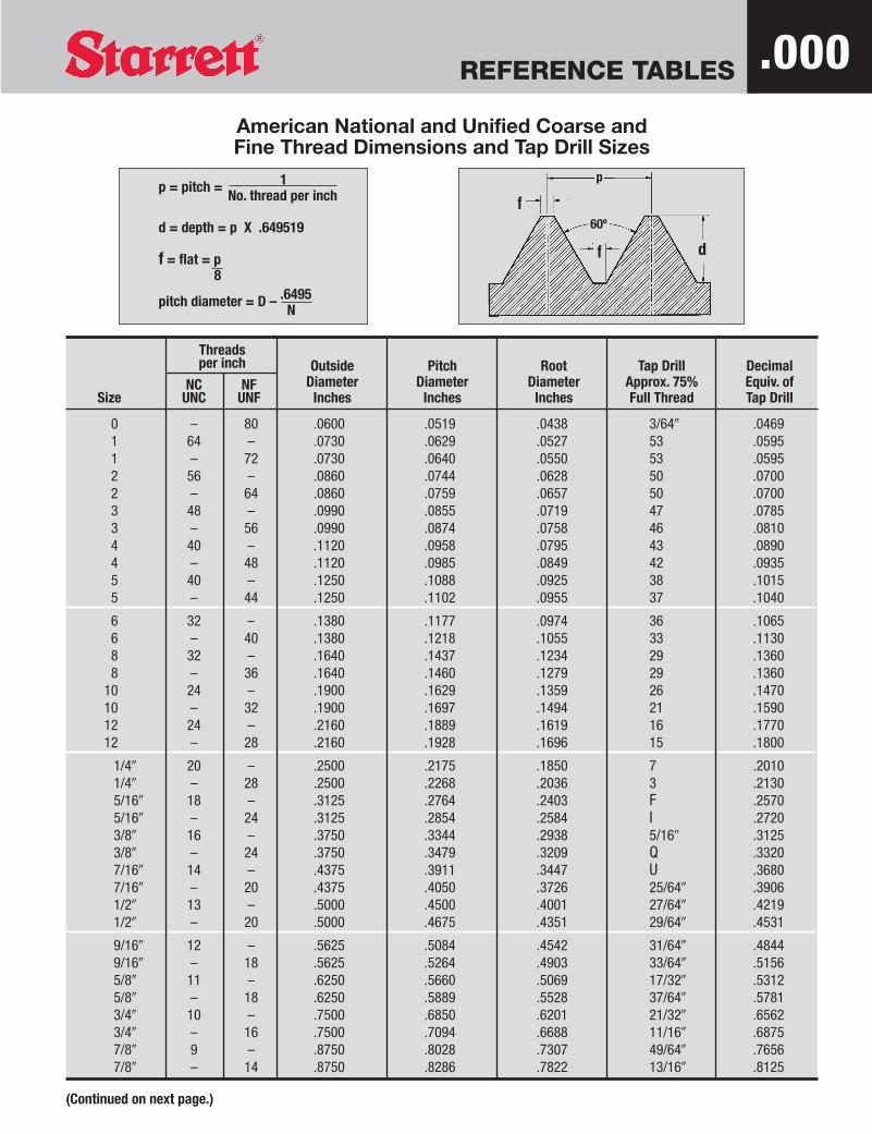
REFERENCE TABLES
Threadsper inch Outside Pitch Root Tap Drill Decimal
NC NF Diameter Diameter Diameter Approx. 75% Equiv. ofSize UNC UNF Inches Inches Inches Full Thread Tap Drill
0 – 80 .0600 .0519 .0438 3/640 .04691 64 – .0730 .0629 .0527 53 .05951 – 72 .0730 .0640 .0550 53 .05952 56 – .0860 .0744 .0628 50 .07002 – 64 .0860 .0759 .0657 50 .07003 48 – .0990 .0855 .0719 47 .07853 – 56 .0990 .0874 .0758 46 .08104 40 – .1120 .0958 .0795 43 .08904 – 48 .1120 .0985 .0849 42 .09355 40 – .1250 .1088 .0925 38 .10155 – 44 .1250 .1102 .0955 37 .1040
6 32 – .1380 .1177 .0974 36 .10656 – 40 .1380 .1218 .1055 33 .11308 32 – .1640 .1437 .1234 29 .13608 – 36 .1640 .1460 .1279 29 .1360
10 24 – .1900 .1629 .1359 26 .147010 – 32 .1900 .1697 .1494 21 .159012 24 – .2160 .1889 .1619 16 .177012 – 28 .2160 .1928 .1696 15 .1800
1/40 20 – .2500 .2175 .1850 7 .20101/40 – 28 .2500 .2268 .2036 3 .21305/160 18 – .3125 .2764 .2403 F .25705/160 – 24 .3125 .2854 .2584 I .27203/80 16 – .3750 .3344 .2938 5/160 .31253/80 – 24 .3750 .3479 .3209 Q .33207/160 14 – .4375 .3911 .3447 U .36807/160 – 20 .4375 .4050 .3726 25/640 .39061/20 13 – .5000 .4500 .4001 27/640 .42191/20 – 20 .5000 .4675 .4351 29/640 .4531
9/160 12 – .5625 .5084 .4542 31/640 .48449/160 – 18 .5625 .5264 .4903 33/640 .51565/80 11 – .6250 .5660 .5069 17/320 .53125/80 – 18 .6250 .5889 .5528 37/640 .57813/40 10 – .7500 .6850 .6201 21/320 .65623/40 – 16 .7500 .7094 .6688 11/160 .68757/80 9 – .8750 .8028 .7307 49/640 .76567/80 – 14 .8750 .8286 .7822 13/160 .8125
American National and Unified Coarse andFine Thread Dimensions and Tap Drill Sizes
p = pitch = 1No. thread per inch
d = depth = p X .649519
f = flat = p8
pitch diameter = D – .6495N
p
d
f
f
60º
(Continued on next page.)
.000
REFERENCE TABLES
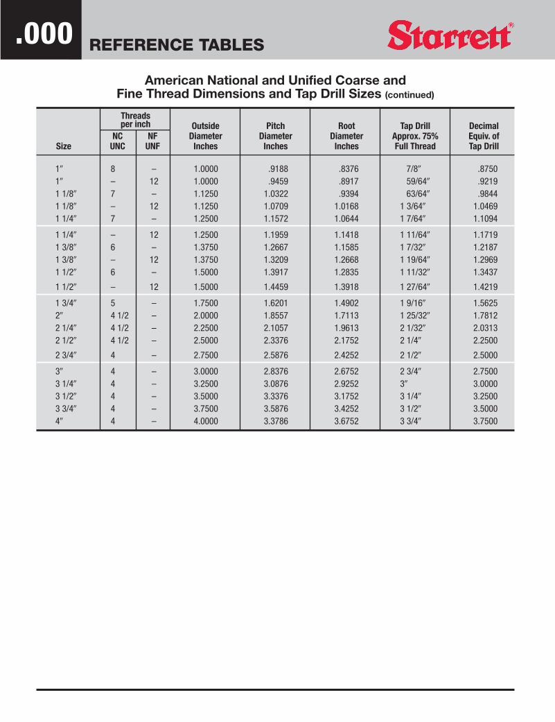
American National and Unified Coarse andFine Thread Dimensions and Tap Drill Sizes (continued)
Threadsper inch Outside Pitch Root Tap Drill Decimal
NC NF Diameter Diameter Diameter Approx. 75% Equiv. ofSize UNC UNF Inches Inches Inches Full Thread Tap Drill
10 8 – 1.0000 .9188 .8376 7/80 .875010 – 12 1.0000 .9459 .8917 59/640 .92191 1/80 7 – 1.1250 1.0322 .9394 63/640 .98441 1/80 – 12 1.1250 1.0709 1.0168 1 3/640 1.04691 1/40 7 – 1.2500 1.1572 1.0644 1 7/640 1.1094
1 1/40 – 12 1.2500 1.1959 1.1418 1 11/640 1.17191 3/80 6 – 1.3750 1.2667 1.1585 1 7/320 1.21871 3/80 – 12 1.3750 1.3209 1.2668 1 19/640 1.29691 1/20 6 – 1.5000 1.3917 1.2835 1 11/320 1.3437
1 1/20 – 12 1.5000 1.4459 1.3918 1 27/640 1.4219
1 3/40 5 – 1.7500 1.6201 1.4902 1 9/160 1.562520 4 1/2 – 2.0000 1.8557 1.7113 1 25/320 1.78122 1/40 4 1/2 – 2.2500 2.1057 1.9613 2 1/320 2.03132 1/20 4 1/2 – 2.5000 2.3376 2.1752 2 1/40 2.2500
2 3/40 4 – 2.7500 2.5876 2.4252 2 1/20 2.5000
30 4 – 3.0000 2.8376 2.6752 2 3/40 2.75003 1/40 4 – 3.2500 3.0876 2.9252 30 3.00003 1/20 4 – 3.5000 3.3376 3.1752 3 1/40 3.25003 3/40 4 – 3.7500 3.5876 3.4252 3 1/20 3.500040 4 – 4.0000 3.3786 3.6752 3 3/40 3.7500
.000
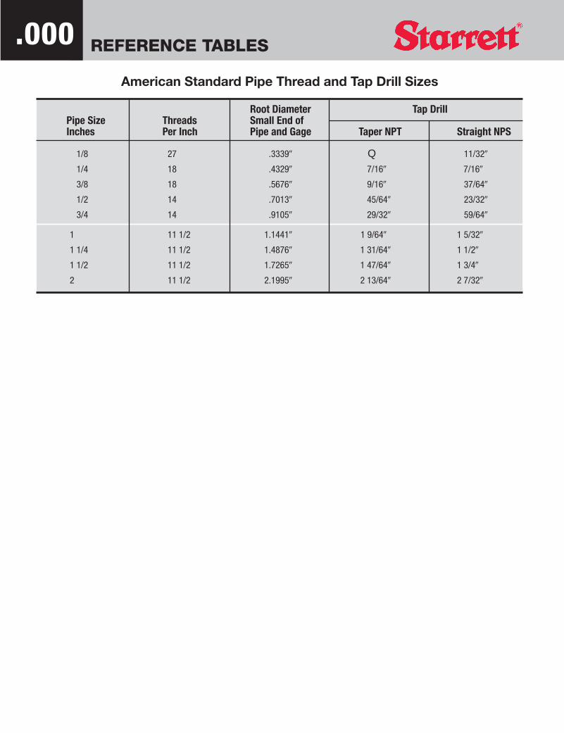
REFERENCE TABLES.000
Root Diameter Tap DrillPipe Size Threads Small End of Inches Per Inch Pipe and Gage Taper NPT Straight NPS
1/8 27 .33390 Q 11/320
1/4 18 .43290 7/160 7/160
3/8 18 .56760 9/160 37/640
1/2 14 .70130 45/640 23/320
3/4 14 .91050 29/320 59/640
1 11 1/2 1.14410 1 9/640 1 5/320
1 1/4 11 1/2 1.48760 1 31/640 1 1/20
1 1/2 11 1/2 1.72650 1 47/640 1 3/40
2 11 1/2 2.19950 2 13/640 2 7/320
American Standard Pipe Thread and Tap Drill Sizes

REFERENCE TABLES .000American Standard Acme Screw Thread Dimensions
h = Basic depth of threadh9 = Depth of thread with clearanceK = Tap drill
Basic minor diameter of nutFc = Width of flat at crest of threadFr = Width of flat at bottom of space
FOR 10 OR LESS THREADS PER INCHh9 = P plus .010
2Fr = .3707 minus .0052
nT = D plus .020
n = Number of threads per inchp = Pitch of threadKr = Minor diameter of screwD = Major diameter of screwT = Major diameter of tap
FOR MORE THAN 10 THREADS PER INCHh9 = P plus .005
2Fr = .3707 minus .0026
nT = D plus .010
Threads Depth of Thread Flat at Flat at Thicknessper inch with Clearance Top of Thread Bottom of Space Space at at Root
(n) (h9) (Fc) (Fr) Top of Thread of Thread
1 .5100 .3707 .3655 .6293 .63451 1/3 .3850 .2780 .2728 .4720 .47722 .2600 .1854 .1802 .3146 .31983 .1767 .1236 .1184 .2097 .21494 .1350 .0927 .0875 .1573 .16255 .1100 .0741 .0689 .1259 .13116 .0933 .0618 .0566 .1049 .11017 .0814 .0530 .0478 .0899 .09518 .0725 .0463 .0411 .0787 .08399 .0655 .0412 .0360 .0699 .075110 .0600 .0371 .0319 .0629 .068112 .0467 .0309 .0283 .0524 .055014 .0407 .0265 .0239 .0449 .047516 .0363 .0232 .0206 .0393 .0419
p
h9
Fr
Fc29º
p = 1n
K = D minus p
Fc = .3707n
Kr = D minus 2h9
REFERENCE TABLES.000
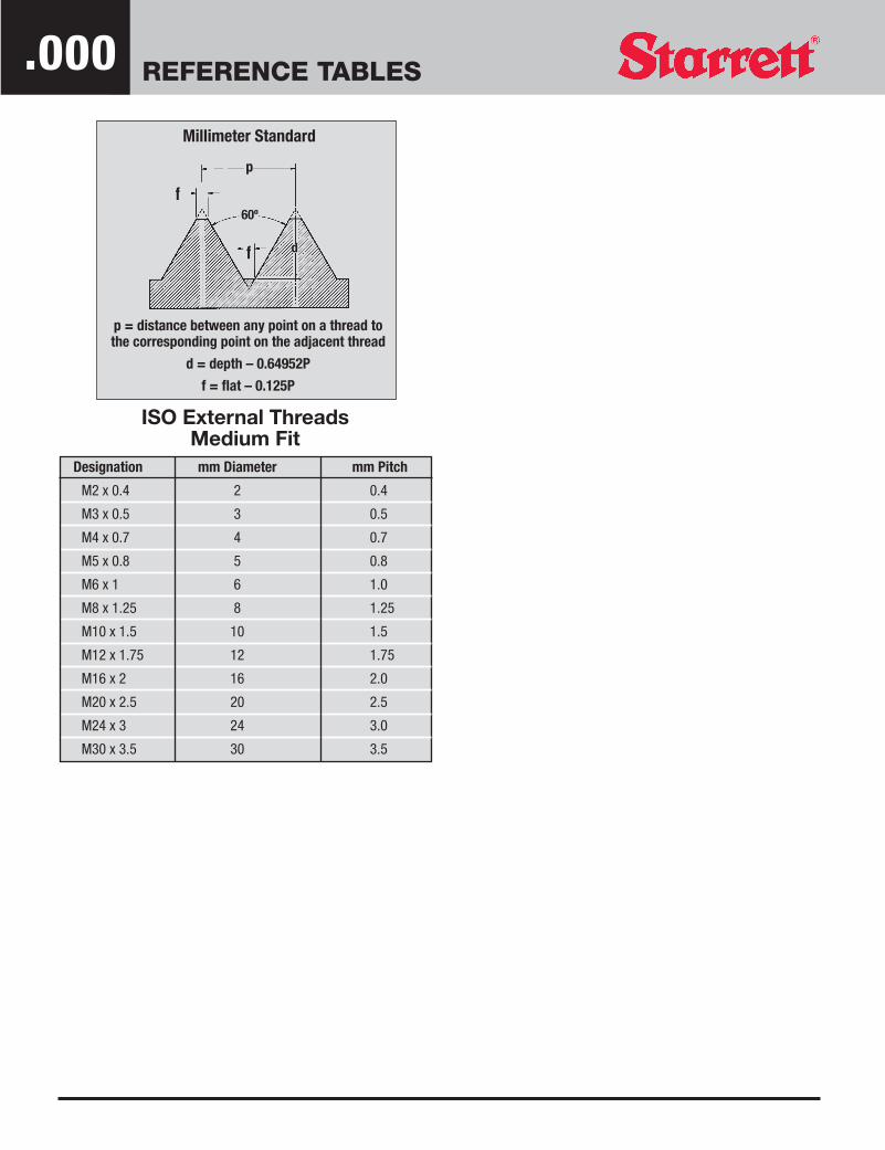
ISO External ThreadsMedium Fit
Millimeter Standard
p = distance between any point on a thread to the corresponding point on the adjacent thread
d = depth – 0.64952P
f = flat – 0.125P
p
d
f
f
60º
Designation mm Diameter mm Pitch
M2 x 0.4 2 0.4
M3 x 0.5 3 0.5
M4 x 0.7 4 0.7
M5 x 0.8 5 0.8
M6 x 1 6 1.0
M8 x 1.25 8 1.25
M10 x 1.5 10 1.5
M12 x 1.75 12 1.75
M16 x 2 16 2.0
M20 x 2.5 20 2.5
M24 x 3 24 3.0
M30 x 3.5 30 3.5
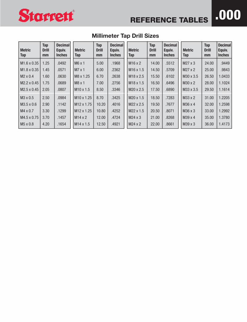
REFERENCE TABLES .000Millimeter Tap Drill Sizes
Tap DecimalMetric Drill Equiv.Tap mm Inches
Tap DecimalMetric Drill Equiv.Tap mm Inches
Tap DecimalMetric Drill Equiv.Tap mm Inches
Tap DecimalMetric Drill Equiv.Tap mm Inches
M1.6 x 0.35 1.25 .0492
M1.8 x 0.35 1.45 .0571
M2 x 0.4 1.60 .0630
M2.2 x 0.45 1.75 .0689
M2.5 x 0.45 2.05 .0807
M3 x 0.5 2.50 .0984
M3.5 x 0.6 2.90 .1142
M4 x 0.7 3.30 .1299
M4.5 x 0.75 3.70 .1457
M5 x 0.8 4.20 .1654
M6 x 1 5.00 .1968
M7 x 1 6.00 .2362
M8 x 1.25 6.70 .2638
M8 x 1 7.00 .2756
M10 x 1.5 8.50 .3346
M10 x 1.25 8.70 .3425
M12 x 1.75 10.20 .4016
M12 x 1.25 10.80 .4252
M14 x 2 12.00 .4724
M14 x 1.5 12.50 .4921
M16 x 2 14.00 .5512
M16 x 1.5 14.50 .5709
M18 x 2.5 15.50 .6102
M18 x 1.5 16.50 .6496
M20 x 2.5 17.50 .6890
M20 x 1.5 18.50 .7283
M22 x 2.5 19.50 .7677
M22 x 1.5 20.50 .8071
M24 x 3 21.00 .8268
M24 x 2 22.00 .8661
M27 x 3 24.00 .9449
M27 x 2 25.00 .9843
M30 x 3.5 26.50 1.0433
M30 x 2 28.00 1.1024
M33 x 3.5 29.50 1.1614
M33 x 2 31.00 1.2205
M36 x 4 32.00 1.2598
M36 x 3 33.00 1.2992
M39 x 4 35.00 1.3780
M39 x 3 36.00 1.4173

REFERENCE TABLES
Tap Drill Sizes For Fractional Size ThreadsApproximately 65% Depth Thread / AMERICAN NATIONAL THREAD FORM
ThreadsTap Size per Inch Hole Diameter Drill
1/16 72 .049 3/641/16 64 .047 3/641/16 60 .046 565/64 72 .065 525/64 64 .063 1/165/64 60 .062 1/165/64 56 .061 533/32 60 .077 5/643/32 56 .076 483/32 50 .074 493/32 48 .073 497/64 56 .092 427/64 50 .090 437/64 48 .089 431/8 48 .105 361/8 40 .101 381/8 36 .098 401/8 32 .095 3/329/64 40 .116 329/64 36 .114 339/64 32 .110 355/32 40 .132 305/32 36 .129 305/32 32 .126 1/811/64 36 .145 2711/64 32 .141 9/643/16 36 .161 203/16 32 .157 223/16 30 .155 233/16 24 .147 2613/64 32 .173 1713/64 30 .171 11/6413/64 24 .163 207/32 32 .188 127/32 28 .184 137/32 24 .178 1615/64 32 .204 615/64 28 .200 815/64 24 .194 101/4 32 .220 7/321/4 28 .215 31/4 27 .214 31/4 24 .209 41/4 20 .201 75/16 32 .282 9/325/16 27 .276 J5/16 24 .272 I5/16 20 .264 17/645/16 18 .258 F3/8 27 .339 R3/8 24 .334 Q3/8 20 .326 21/643/8 16 .314 5/167/16 27 .401 Y7/16 24 .397 X7/16 20 .389 25/647/16 14 .368 U1/2 27 .464 15/321/2 24 .460 29/64
ThreadsTap Size per Inch Hole Diameter Drill
1/2 20 .451 29/641/2 13 .425 27/641/2 12 .419 27/649/16 27 .526 17/329/16 18 .508 33/649/16 12 .481 31/645/8 27 .589 19/325/8 18 .571 37/645/8 12 .544 35/645/8 11 .536 17/3211/16 16 .627 5/811/16 11 .599 19/323/4 27 .714 23/323/4 16 .689 11/163/4 12 .669 43/643/4 10 .653 21/3213/16 12 .731 47/6413/16 10 .715 23/327/8 27 .839 27/327/8 18 .821 53/647/8 14 .805 13/167/8 12 .794 51/647/8 9 .767 49/6415/16 12 .856 55/6415/16 9 .829 53/64
1 27 .964 31/321 14 .930 15/161 12 .919 59/641 8 .878 7/81 1/16 8 .941 15/161 1/8 12 1.044 1 3/641 1/8 7 .986 63/641 3/16 7 1.048 1 3/641 1/4 12 1.169 1 11/641 1/4 7 1.111 1 7/641 5/16 7 1.173 1 11/641 3/8 12 1.294 1 19/641 3/8 6 1.213 1 7/321 1/2 12 1.419 1 27/641 1/2 6 1.338 1 11/321 5/8 5 1/2 1.448 1 29/641 3/4 5 1.555 1 9/161 7/8 5 1.680 1 11/162 4 1/2 1.783 1 25/322 1/8 4 1/2 1.909 1 29/322 1/4 4 1/2 2.034 2 1/322 3/8 4 2.131 2 1/82 1/2 4 2.256 2 1/42 5/8 4 2.381 2 3/82 3/4 4 2.506 2 1/22 7/8 3 1/2 2.597 2 19/323 3 1/2 2.722 2 23/323 1/8 3 1/2 2.847 2 27/323 1/4 3 1/2 2.972 2 31/323 3/8 3 1/4 3.075 3 1/163 1/2 3 1/4 3.200 3 3/163 5/8 3 1/4 3.325 3 5/163 3/4 3 3.425 3 7/164 3 3.675 3 11/16
.000

REFERENCE TABLES .000
Included Angle Angle With Center LineTaper Taper Taper per inch
per Foot Degree Minute Second Degree Minute Second per inch from Center Line
1/80 0 35 47 0 17 54 .010416 .0052081/40 1 11 38 0 35 49 .020833 .0104163/80 1 47 25 0 53 42 .031250 .015625
1/20 2 23 12 1 11 36 .041667 .0208335/80 2 59 3 1 29 31 .052084 .0260423/40 3 34 48 1 47 24 .062500 .0312507/80 4 10 32 2 5 16 .072917 .036456
10 4 46 19 2 23 10 .083330 .0416671 1/40 5 57 45 2 58 53 .104166 .0520841 1/20 7 9 10 3 34 35 .125000 .0625001 3/40 8 20 28 4 10 14 .145833 .072917
20 9 31 37 4 45 49 .166666 .0833322 1/20 11 53 38 5 56 49 .208333 .104166
30 14 2 0 7 1 0 .250000 .1250003 1/20 16 35 39 8 17 49 .291666 .145833
40 18 55 31 9 27 44 .333333 .1666664 1/20 21 14 20 10 37 10 .375000 .187500
50 23 32 12 11 46 6 .416666 .20833360 28 4 20 14 2 10 .500000 .250000
Tapers and Angles
Mechanical Terminology

A1
Mechanical Terminology
AMS Aeronautical Material Specification is material and process specifications for aircraft components conforming to industry approved engineering and metallurgical practices in the aircraft and space industries. They are developed by an SAE committee. All specifications will state "AMS".
AN Dimensional standards for aircraft fasteners developed by the Aeronautical Standards Group. All drawings are prefixed by "AN"
ASTM Standards developed by the American Society for Testing and Materials.
Acorn Die A form of threading die for use in screw machines. The cutting portion resembles an acorn.
Acorn Nut A blind tapped hex nut with an acorn shaped top. Provides sealing for projecting threaded parts.
Age Hardening A process of aging that increases hardness and strength, and ordinarily decreases ductility. Age hardening usually follows rapid cooling or cold working.
ASME Dimensional standards for fasteners, etc., developed by the American Society of Mechanical Engineers
Angle of Head In countersunk heads, the included angles of the conical underportion or bearing surface, usually 82 or 100 degrees.
Balls Used in "quick release pins" where permanent assemble and disassemble action tales place. Provides a reliable holding fastener.
Barrel Nut An internally threaded screw having a slotted head.
Bent Bolt A cylindrical rod having a thread at one end and the other end bent to some desired conformation; also a bent cylindrical rod having threads at both ends.
Bevel A surface not at right angles to the rest of the piece.
Binding Head Rounded top surface and slightly tapered sides. The bearing surface is flat with annular undercut optional.
Blind Rivet A rivet designed for use where only one side of the work is accessible.
Blunt Start The removal of the partial thread at the entering end of thread.
Body of Bolt or Screw Also designated grip. The blank portion of the bolt or screw which is between the thread and the head.
A2
Mechanical Terminology
Bolt Blank A headed rod or bar intended for a subsequent threading operation.
Bolt End A headless rod threaded at one end and assembled with a square nut, designed to be welded or otherwise fastened to a part or structure.
Brielle Hardness Test A method of determining the hardness of metallic materials by applying a known load to the surface of the material through a hardened steel ball of known diameter. The diameter (or depth) of the resulting impression in the metal is measured. The Brielle hardness number is taken as a quotient of the applied load divided by the area of the surface impression which is assumed to be spherical.
Broaching A generating process whereby metal is removed with a multiple-point tool, usually a bar, with tooth height increasing from the starting end. When the broach is pulled or pushed through or over the work, each tooth removes a clip of uniform thickness, in contrast to a milling cutting tooth which removes a wedge-shaped chip.
Button Die Small adjustable dies for screw machines and similar work, supported in a ring holder.
Burnish To smooth or polish by a rolling or sliding tool under pressure.
Cap Nut A blind tapped hex nut with an acorn-shaped top. Provides sealing for projecting thread parts.
Cap Screws Term used to describe hexagon head, slotted head, square head and socket head cap screws.
Captive Screws Where the shank above the threaded portion is undercut lower than the threaded portion.
Carbide A compound of carbon with one or more metallic elements.
Carbide Tools Tools with cutting points of tungsten, tantalum or other alloys of sintered carbides.
Carbon Steel Any steel made by combining carbon with iron.
Carriage Bolts A round or flat head bolt with a square neck to prevent rotation. Used in wood assemblies.
Case Harden Hardening a ferrous alloy so that the outer portion or case is made substantially harder than the inner portion or core. Typical processes used for case hardening are carburizing, cyaniding, carbonitriding, nitriding, induction hardening, and flame hardening.

A3
Mechanical Terminology
Casting A term applied to the act of pouring molten metal into a mold. 2. The metal object produced by such pouring.
Castle Nut A hexagon nut having a cylindrical portion at the end opposite to the bearing face, with opposed slots in this portion which are parallel to the axis, designed for insertion of a cotter to secure the nut in place when used with a drilled fastener.
Centerless Grinding Grinding the outside or inside diameter of a round piece not mounted on centers.
Chamfer To bevel a sharp external edge. (n) A beveled edge.
Chasing Threads Cutting screw threads by moving a tool along the axis of the work to be threaded.
Chatter Rough or unsatisfactory surfaces on work. It is usually caused by a slight jumping of the tool away from the work or of the work away from the tool.
Check Nut A double chamfered hexagon machine screw nut Class 3B fit. (AN 316).
Chip The metal removed by a tool.
Chuck Device for holding work in machine tools.
Class of Thread Class of threads are distinguished from each other by the amount of tolerance or tolerance and allowance specified. Classes 1A, 2A, and 3A apply to external threads, and Classes 1B, 2B and 3B apply to internal threads.
Clevis U-shaped shackle for connecting a rod to a pin.
Clevis Pins A headed dowel pin with a drilled shank that accepts a cotter pin. Used as a fastener where more than temporary holding actions is required. (ASA B 5.20-1958).
Clinch Nut A nut having a pilot which, after insertion in a hole, is clinched or staked in place to prevent rotation.
Cold Heading Forcing metal to flow cold into dies to form thicker sections and more or less intricate shapes. The operation is performed in specialized machines where the metal, in the form of a wire or bar stock, may be upset or headed in certain sections to a larger size and, if desired, may be extruded in other sections to a smaller diameter than the stock wire.
Cold Swaging Process A method of reducing or forming steel or other material while cold, by drawing to a point or reducing the diameter, as may be required.

A4
Mechanical Terminology
Cold Work To deform metal stock by hammering, forming, drawing, etc., while the metal is at ordinary room temperature.
Columbium A metal which may be added to chrome-nickel stainless steel to improve its welding and general heat-resistant qualities, by preventing carbide precipitation.
Companion Flanges Shaft attached collars of 18-8 stainless steel into which a threaded piece may be joined. Has standard I.P.S. threads.
Comparator A device for inspecting screw threads and outlines by comparing them with a greatly enlarged standard chart.
Cone Point A point in the form of a cone, commonly having an included angle of 90 degrees or 118 degrees when applied to set screws.
Copper Steel When any minimum copper content is specified, the steel is classed as copper steel. The copper is added to enhance erosion resistance of the steel.
Corrosion Gradual chemical or electrochemical attack on a metal by atmosphere, moisture or other agents.
Cotter Pin Used as a locking device in clevis pins, castellated nuts and slotted nuts with drilled bolts. Ends available in various types such as "extended mitre end", etc.
Counterbore To enlarge a hole to a given depth. --- The cylindrical enlargement of the end of a drilled or bored hole. ---- A cutting tool for counterboring, having a piloted end of the size of the drilled hole.
Countersunk Head A head, the underside of which is beveled to fit a flaring hole. The bearing surface of other types of heads is generally perpendicular to the body axis.
Crest That surface of the thread which joins the flanks of the thread and is farthest from the cylinder or cone from which the thread projects.
Crest Clearance As in a thread assembly, the distance, measured perpendicular to the axis, between the crest of a thread and the root of its mating thread.
Crest Truncation of Thread The distance, measured perpendicular to the axis, between the sharp root and the cylinder or cone which bounds the root.
Cup Point A point in the form of a cone, commonly having an included angle of 90 degrees, with a conical depression in the end commonly having an included angle of 118 degrees. The contact area is a circular ridge which has considerable holding power with slight penetration, applied to set screws generally.
A5
Mechanical Terminology
Deburring The removal of burrs by a secondary operation such as grinding.
Deep Drawing Forming shaped articles or shells by forcing sheet metal into a die.
Die One of a pair of hardened metal blocks for forming, impressing, or cutting out a desired shape. Or (thread). A tool for cutting external threads. Opposite of tap.
Die Casting A very accurate and smooth casting made by pouring a molten alloy usually under pressure into a metal mold or die.
Die Chaser The separate cutting tools used in die heads, which actually cut the screw threads.
Dog Point A cylindrical extension, or pilot, of diameter smaller than the minor diameter of the thread, commonly equal to about D/2 in length, with a conical section between it and the thread; usually used as a pilot in assembling or as the end of a set screw projecting into a fairly deep hole or slot.
Double End Stud Threaded at both ends with standard Class 2A threads to take nut assembly.
Dowel Pins Used as a holding pin with chamfered on one end. Drilled headed dowel pin (clevis pin) used - frequently removed fastener.
Dowel Screw Both ends have Gimlet points, threaded similar to a Lag Bolt. The center section has a plain unthreaded shoulder. Used in joining two wooden members such as a leg to a table top.
Drill To sink a hole with a drill, usually with a twist drill. ---- A pointed cutting tool rotated under pressure.
Drilled Head or Shank Used in AN Bolts and Machine Screws, etc.
Drive Screw A piloted, multiple threaded screw with a large helix angle, used for permanent applications. It forms a mating thread as it is hammered or pressed into a prepared hole.
Driver Head A head, on a bolt or screw, designed for driving the fastener by means of a tool other than a wrench, such as a screw driver.
Drop Forging Forming metal, usually under impact, by compression within dies designed to produce the required shape.
Elevator Bolt A flat, plain, circular countersunk head bolt with a square neck to prevent rotation.
Endurance Limit The maximum stress that a metal will withstand without failure during a specified large number of cycles of stress.

A6
Mechanical Terminology
Escutcheon Pin A piece generally used to join a plate or shield, to cover or protect softer or more delicate materials or actions.
Expansion Bolt A combination of a "lag bolt" and an internally threaded split sleeve, designed for fastening to stone or concrete by inserting a sleeve into a hole in the concrete and expanding to a tight fit in the hole by turning the lag both with a wrench.
Eyebolt A bolt having a head in the form of an open or closed anchor ring, or of a flattened and pierced section, with or without a collar or shoulder under the head.
Face To machine a flat surface perpendicular to the axis at rotation on a lathe.
Fatigue Strength The stress to which a metal can be subjected for a specified number of cyclic changes of stress.
Feather Key A parallel key fastened in either the shaft or in the hub of a member sliding on it. When fastened in the shaft, it must be long enough to hold or drive the sliding member in any of its positions on the shaft. When in the sliding member the key need only be as long as the hub.
Fillet A rounded filling of the internal angle between two surfaces.
Fillister Head Rounded top surface, cylindrical sides, and a flat bearing surface.
Fin A thin projecting rib.
Finished Hexagon Bolts A washer faced or chamfered bearing surface with a close body tolerance.
Fin Neck Carriage Bolt A plain, circular, oval head bolt with two oppositely located fins to prevent rotation.
Fit The general term used to signify the range of tightness which may result from the application of a specific combination of allowances and tolerances in the design of mating parts. See "Class of Thread"
Flat Head Flat top surface and a conical bearing surface.
Flex-Loc* When used as a stop or lock nut, the locking threads of the slotted top press inward against the bolt, lifting the nut upward and causing the remaining threads to bear against the lower surface of the bolt threads. (*TM)
Following Flank The flank of a thread opposite to the leading flank.
A7
Mechanical Terminology
Forge To shape metal while hot and plastic by a hammering or forcing process. Dies used in process.
Form of Thread The profile of a thread in an axial plane for a length of one pitch.
Free Machining The property that makes machining easy because of the forming of small chips, a characteristic imparted dot steel by sulfur, etc.
Full Annealing Annealing a ferrous alloy by austenitizing and then cooling slowly through the transformation range.
Full-Size Body The body of a bolt or screw which has a diameter between the minimum and maximum limits of the major diameter of the thread.
Galvanize To treat with a bath of lead and zinc to prevent rusting
Gimlet Point A taper-threaded point; applied to wood screws, Type A tapping screws, lag bolts, etc.
Grind To finish or polish a surface by means of an abrasive.
Grip The unthreaded portion of a bolt or screw.
Half Dog Point The same as a dog point but half as long; used on short screws for the same purposes as the dog point, but in a shallower hole or slot.
Hanger Bolt One end is gimlet pointed and has a wood screw thread. The other end consists of a coarse machine screw thread. The center section is unthreaded.
Hardenability In a ferrous alloy, the property that determines the depth and distribution of hardness induced by quenching.
Hardening A method of heat treating metals by heating to a temperature within, or above, the critical range, holding at that temperature for a given time, and then cooling rapidly, usually by quenching in oil or water.
Hardness Resistance to plastic deformation by indentation, penetration, scratching or bending.
Head The preformed, enlarged end of a bolt, screw, pin, or rivet, provided with a bearing surface which is usually either flat or conical.
Header Point A chamfer point, usually of 45 degrees included angle, forming by a die at the time of heading and prior to threading.

A8
Mechanical Terminology
Head Marking Used to identify the material used in a fastener such as a bolt or cap screw. The marking is either raised or indented to specifications.
Heat Treating An operation involving the heating and cooling of a metal to obtain certain desirable conditions or properties.
Height of Thread The distance, measured perpendicular to the axis, between the major and minor cylinders or cones, respectively.
Heli-Coil Coil of wire used as an insert to accept a screw or bolt and adding holding power by forcing itself between the fastener and the walls of the recess when the fastener is driven in.
Hexagonal A recessed hexagon socket in the head of a cap or set screw to add greater tightening and loosening power. Used with a Hex key wrench. (See Hexagon Head)
Hexagon Head Flat top surface with hexagonal sides and with a flat bearing surface. (Six Sides)
Hook Bolt A "bent bolt" having the unthreaded end bent to form a hook, such as a round bend, square bend, right-angle bend, or acute-angle bend hook bolt.
Hot Forming Working operation such as bending and drawing sheet and plate, forging, pressing, and heading, performed on metal heated to temperatures above room temperature.
Immunize To remove small particles of iron or grit from the surface of stainless steel by pickling in an acid solution.
Impact Test A test to determine the energy absorbed in fracturing a test bar at high velocity. The test may be in tension or in bending, or it may properly be a notch test if a notch is present, creating multi-axel stresses.
Included Angle of Thread The angle between the flanks or the thread measured in an axial plane.
Incomplete Thread On straight threads, that portion at the end having roots not fully formed by the lead or chamfer on threading tools
Ingot Steel formerly in a molten state, transferred to an ingot mold to solidify.
Interference Fit A thread fit having limits of size so prescribed that an interference always results when mating parts are assembled.
Internal Thread A thread on the internal surface of a hollow cylinder or cone.
A9
Mechanical Terminology
International Metric Thread System A thread form similar to the American standard, excepting the depth which is greater. There is a clearance between the root and mating crest fixed at a maximum of 1/16 the height of the fundamental triangle or 0.054 x pitch. A rounder root profile is recommended. The angle in the plane of the axis is 60 degrees and the crest has a flat like the American standard equal to 0.125 pitch.
Iron Primarily the name of a metallic element. In the steel industry, iron is the name of the product of a blast furnace containing 92 to 94 percent iron. Other names for blast furnace are pig iron and hot metal.
J-Bolt A "bent bolt" having the unthreaded end reverse bent to approximately a semicircle.
Jackson Head A machine screw with a small oval head. (Trimmed oval head).
Jam Nut A second nut forced or jammed against the main nut to prevent loosening. A thin nut.
Key A small block or wedge inserted between shaft and hub to prevent circumferential movement.
Keyslot The recess cut for Woodruff keys produced by sinking a milling cutter of the right diameter and width into a shaft.
Keyway A groove or slot cut to fit a key. A key fits into a key seat and slides into a keyway.
Knurl A roughened surface produced by contact with a wheel which forces metal above the surface while making indentations below the surface.
Lag Bolt A fastener having a square head, with a gimlet or cone point, and a thin, sharp, coarse-pitch thread, designed for insertion in wood or other resilient materials and producing its own mating thread.
Lead Error A variation in the distance between the threads of a screw.
Left-Hand Thread A thread is a left-hand thread, if, when viewed axially, it winds in a counter-clockwise and receding direction. All left-hand threads are designated LH.
Length of Fastener The length of a flat bearing surface fastener is the distance, in a line parallel to the axis, from the bearing surface to the extreme point. The length of a countersunk head fastener is the distance, in a line parallel to the axis, from the largest diameter of the bearing surface to the extreme point.
Lentil Head Screw Obsolete term for oval head screw.

A10
Mechanical Terminology
Liquid Honing A metal finishing process by forcing a stream of liquid, in which a very fine abrasive is suspended, against the surface to be finished.
Lock Nut A nut which, in addition to serving the purposes of an ordinary nut, has a special means for gripping a threaded member so that a relative rotation between the nut and the threaded companion member is prevented in use.
MS Specifications (Military Standard)
Machineability Relative ease or difficulty in forming.
Magnaflux A magnetic method of determining surface and subsurface defects in metals.
Major Diameter On a straight thread, the diameter of the coaxial cylinder which would pass through the crests of an external thread or the roots of an internal thread.
Master Gage A thread-plug gage which represents the physical dimensions of the nominal or basic size of the part. It clearly establishes the minimum size of the threaded hole and the maximum size of the screw at the point at which interference between mating parts begin.
Maximum Material Limit The maximum limit of size of an external dimension or the minimum limit of size of an internal dimension.
Mechanical Properties Those properties of a material that reveal the elastic and inelastic reaction when force is applied, or that involve the relationship between stress and strain; for example, the modulus of elasticity, tensile strength and fatigue limit.
Micro-Inch One millionth of an inch. Used in measuring imperfections of surface finishes.
Milling Process A machining process whereby a surface is generated with a rotating toothed cutter. Each tooth takes an individual chip.
Minor Diameter On a straight thread, the minor diameter is the diameter of the coaxial cylinder which would pass through the roots of an external thread.
Monel A corrosion resisting metal consisting essentially of two-thirds nickel and one-third copper.
NAS Drawings and Specifications Dimensional and material standards for aircraft fasteners developed by the National Aerospace Standards Committee. All drawings and specifications are prefixed by "NAS".
Nail Point A sharp pyramidal point of approximately 30 degrees or 45 degrees included angle.

A11
Mechanical Terminology
Naval Brass A corrosion resistant metal containing 60 per cent copper, 39 1/4 per cent zinc and 3/4 per cent tin.
Neck A portion reduced in diameter between the ends of a shaft.
Nickel A silver-white metal usually used as an alloy in steel, bronze, brass and cast iron. It tends to increase corrosion resistance.
Nipple A short piece of threaded pipe used to connect two fittings.
Nifriding A surface hardening process used on ferrous metals by heating the metal in contact with ammonia gas or other nitrogenous material.
Non-Ferrous Metal Metals or alloys without an appreciable amount of iron. Examples are aluminum, brass, copper, etc.
Non-Magnetic Steels with sufficient quantities of manganese or nickel to render the steel non-magnetic. 18-8 (300 series chrome-nickel steel) is non-magnetic when annealed. Type 316 is non-magnetic in all conditions. (See pg. 156 of the Data Book).
Normalize To remove internal stresses by heating a metal piece to its critical temperature and allowing it to cool very slowly.
Nut A metal block (solid nut) or sleeve having an internal thread made to assemble with the external thread on a bolt, screw, or other threaded part. It may be a fastening means, an adjusting means, a means for transmitting motion, or a means for transmitting power with large mechanical advantage and nonreversible motion.
Nylon Fasteners Fasteners made of a material that has a low dielectric constant and relatively high tensile strength, enabling it to resist high voltage at commercial frequencies. It can also operate at continuous temperatures as high as 250 degrees F. Any temperatures above has an effect to oxidize material. Electric and electronic equipment manufacturers are finding many corrosion-resistant applicable for this type of fastener.
One-Way Head Screw A round head screw which is slotted but has side clearances at diagonally opposite sides of the slot so that the screw can be driven only in the direction of assembly, designed for preventing tampering.
Open Washer A washer with one side open so as to be removed or put under a nut without removing the nut.
Oval Binding Head Screw Obsolete term for a truss head screw.

A12
Mechanical Terminology
Oval Head Rounded top surface and a conical bearing surface with an included angle usually of 82 degrees.
Oval Point A rounded end which is used, particularly for set and adjusting screws, to apply pressure without cutting action.
Oven Head Screw Obsolete term for truss head screw.
Pan Head Flat top surface rounded into cylindrical sides, and a flat bearing surface. The recessed pan head has a rounded top surface blending into cylindrical sides and a flat bearing surface.
Passivate A process of surface treatment for neutralizing stainless steels. A n oxidizing solution, such as nitric acid is applied to the surface. This strengthens the normal protective film which helps in resisting corrosion. It also removes any foreign substance which might cause local corrosion.
Pattern Nuts Special nuts usually furnished in plain or chamfered face unless otherwise specified, and threads are unified Coarse or unified Fine, Class 2B. (also small and extra small)
Peening The stretching of metal by hammering or rolling the surface.
Phillips Recessed Head A type of screw drive having a cross recess with a wide center opening, steep walls and a blunt conical bottom. Permits easy and rapid entrance of the 4-winged driver.
Physical Properties Those properties familiarly discussed in physics, including those described under mechanical properties; for example, density, electrical conductivity, co-efficient of thermal expansion.
Pinch Point A sharp conical point, usually of 45 degrees included angle, formed by a pinching operation.
Pipe Caps A cap that threads onto a pipe (like a nut) to seal one end.
Pipe Fittings The term applying to all forms of connecting parts which join pieces of pipe together.
Pipe Plugs A short piece of threaded pipe, Slotted, Square Head or Socket, used to close up one end of a fitting.
Pipe Screw Thread American Standard pipe threads are tapered 1 inch in 16, or 3/4 inch per foot. They are 60 degree threads, of National form with flat or rounded top and bottom.

A13
Mechanical Terminology
Pitch The distance, measured parallel to its axis, between corresponding points on adjacent thread forms in the same axial plane and on the same side of the axis.
Pitch Diameter On a straight thread, the diameter of the coaxial cylinder, the surface of which would pass through the thread profiles at such points as to make the width of the groove equal to one-half of the basic pitch. On a perfect thread this occurs at the point where the widths of the thread and groove are equal.
Pitch Line A generator of the cylinder or cone of a screw thread specified in the definition of pitch diameter.
Plain Sheared Point The end of a fastener cut approximately flat and square to the axis, without chamfer.
Planer Head Bolt A bolt having a large low square head, designed for insertion in T-slots of planer, shaper, or milling machine tables.
Plate The electro-chemical coating of a metal piece with a very different metal.
Polish To make smooth or lustrous by friction with a very fine abrasive.
Precipitation Hardening Hardening caused by the precipitation of a constituent from a supersaturated solid solution.
Precision Machine Screws Slotted machine screws, milled from bar, cut thread, and are machined finished Class 3A fits.
Process Annealing Heating a ferrous alloy to a temperature close to, but below, the lower limit of the transformation range and then cooling, in order to soften the alloy for further cold working.
Punch To perforate by pressing a non-rotating tool through the work.
Quench Hardening Hardening a ferrous alloy by austenitizing and then cooling rapidly enough so that some or all of the austenite transforms to martensite.
Quenching Rapid cooling. When applicable, the following more specific terms should be used: direct quenching, fog quenching, hot quenching, interrupted quenching, selective quenching, spray quenching, and time quenching.
Ream To finish a drilled or punched hole very accurately with a rotating fluted tool of the required diameter.
Reamer Tool used for enlarging holes previously formed by drilling or boring.

A14
Mechanical Terminology
Recessed Head A screw head, having specially formed indentations or recesses centered on the head, into which a suitably formed driver fits.
Relief The amount one plane surface of a piece is set below or above another plane, usually for clearance or for economy in machining.
Ribbed Neck Carriage Bolt A plain, circular, oval head bolt with a serrated neck to prevent rotation.
Right-Hand Thread A thread is a right hand thread if, when viewed axially, it winds in a clockwise and receding direction.
Rivet A headed metal fastener of some malleable material used to join parts, as metal plates, of structures and machines by inserting the shank through a hole in each piece and forming a head on the headless end.
Rivet Bolt A bolt designed as a substitute for rivets, having a button head, a ribbed shank, a UNC thread, or a special thread such as a Dardalet thread or Lok-Thread (TM).
Rockwell Hardness Test A measure of hardness by determining the depth of penetration of a pentrator into the specimen under certain fixed conditions of test. The penetrator may be either a steel ball or a diamond sphero- conical penetrator. The hardness number is related to the depth of indentation and the higher the number the harder the material.
Rod Ends The ends of connecting rods which fit over crank pins or cross head pins.
Roll Threading Applying a thread to a bolt or screw by rolling the piece between two grooved die plates, one of which is in motion, or between rotating grooved circular rolls.
Rolled Point The point frequently produced by the cupping of the last 1 to 1 1/2 threads by the thread rolling pressure. This type of point is not produced intentionally but is considered as an alternative form of the plain sheared point.
Root That surface of the thread which joins the flanks of adjacent thread forms and is identical with or immediately adjacent to the cylinder or cone from which the thread projects.
Round Head Semi-elliptical top surface and flat bearing surface.
SAE Specifications Standards developed by the Society of Automotive Engineers, Inc.
SAE Standard Screw Threads The SAE Screw Thread Standard, as revised in 1954, conforms to the Unified and American Standard (ASA B1.1-1949).
A15
Mechanical Terminology
Secondary Operations Operations which include punching, shaving, trimming, drilling, sawing, milling, pointing, tapping and polishing, etc., are generally called secondary.
Self-Locking Where binding action is self-induced on the body of the bolt, screw or nut to keep it rigid and prevent movement and vibration.
Semi-Finished Hexagon Bolts Bolts with standard sizes ranging from 1/4" through 4". Class 2A tolerance. The bearing surface is washer faced.
Set Screw Points A screw with various type points, cup, cone, flat, oval, half dog, full dog, hanger or knurled, used to hold or "set" a collar on a shaft or hold pieces of this kind against movement. Screws are usually short, threaded entire length with the various type points for different applications against this movement.
Screw Stock Metal in the form of wire or rod, ordinarily a free-machining type of alloy, used for making screw machine products.
Screw Thread A ridge of uniform section in the form of a helix on the external or internal surface of a cone or frustum of a cone. A thread formed on a cylinder is known as a straight or parallel thread, to distinguish it from a taper thread which is formed on a cone of frustum of a cone.
Screw Thread Chasers Cutting tools having teeth spaced to match the pitch of the threads to be cut.
Set Screw An externally threaded fastener with or without a head and having a formed point, designed to prevent relative movement of parts when screwed through one part upon or into another part.
Shear To cut off sheet or bar metal between two blades.
Shear Nut A fine threaded thin Castle or slotted nut.
Shear Strength The stress required to produce fracture when impressed vertically upon the cross-section of a material. Expressed in psi.
Shim A thin spacer of sheet metal used for adjusting.
Shoulder Stud A stud similar to a collar stud but having the plain portion of a uniform diameter which is larger than the major diameter of the thread, used where the design requirements do not permit the separation of parts produced by a collar.
Single Thread A single-start thread having lead equal to the pitch.
A16
Mechanical Terminology
Sleeve Nut A long nut with right or left threads for connecting two rods to make an adjustable member.
Slip Washer A washer with an opening large enough to slip the washer over a bolt, and under the bold head. Also called a C washer.
Slotted Head The head, of a bolt or screw, which has one or more slots across the top to fit a screw driver.
Slotted Nut A hexagon nut having opposed slots at the end opposite to the bearing face which are perpendicular to the axis, designed for insertion of a cotter to secure the nut in place when used with a drilled fastener.
Slotted Pin A pin that has a slot, either a square or round bottom, into which an external clip or key is affixed in a locking position.
Socket Head A recessed head in which the sides of the recess are parallel to the body axis, into which a wrench fits. The recess is commonly hexagonal or fluted in form. Also designated as "internal wrenching head".
Spacers Pieces designed to prevent crushing of sandwich-type and other lightweight structural materials at fastening points. Sometimes called inserts.
Spacers, Threaded Spacers with threads through which a bolt can be put. This saves weight by eliminating the nut and the reduction of the bolt length.
Spade Screws A threaded, round body with a finger tightening projection. (Regular Offset or Bent). Primarily used in places needed for frequent adjustments or for knock-down assemblies.
Spanner Screws Special unslotted screws surface, in Round undrilled, Flat drilled and others, which require a special wrench.
Spanner Wrenches Tools used to turn and tighten spanner screws.
Spin To shape sheet metal by forcing it against a form as it revolves.
Spline Raised portions of a shaft which fit into corresponding grooves in a pulley or some sliding member. They can either permit end movement or can be used as permanent fastening.
Spline Nut A nut having external splines or ribs which hold it in place when forced into a hole of slightly smaller diameter.
Spline Socket A recessed socket in the head of a bolt or screw to develop greater torque or driving ease without "round" the recess.
A17
Mechanical Terminology
Split Rivet A small rivet having a split end for securing by spreading the ends.
Spot-Face To finish a round spot on a rough surface, usually around a drilled hole, to give a good seat to a screw or bolthead, cut, usually 1/16 inch deep.
Spring Lockwasher A hardened coil wire having a slightly trapezoidal section after forming which functions as a spring take-up device to compensate for developed looseness and the loss of tension between the parts of an assembly and to prevent the nut from turning.
Square Neck Carriage Bolt A plain, truss or oval head bolt with a square neck to prevent rotation.
Square Nuts Nuts that are square rather than hexagonal.
Stainless A trade name given to alloy steel that is corrosion and heat resistant. The chief alloying elements are chromium, nickel and silicon in various combinations with a possible small percentage of titanium, vanadium, etc. ------ By AISI definition, a steel is called "Stainless" when it contains 4 per cent or more chromium.
Stainless Steel Any steel containing four or more per cent chromium is classified as stainless.
Step Bolt A plain, circular, oval head bolt with a square neck to prevent rotation.
Stress Relieve Heating to a suitable temperature, holding long enough to reduce residual stresses and then coiling to minimize the development of new residual stresses.
Stripper Bolt Discarded term for a shoulder screw.
Structure Machine Screws A Flat Head Machine Screw (AN509C) with one included angle approximately 100 degrees. Usually made in slotted and recessed head types. With a "grip" or unthreaded body at the head.
Stud A threaded rod. It may be threaded at both ends or continuous.
Swage To shape metal by hammering or pressure with the aid of a form or anvil called a "swage block".
Tap To cut threads in a hole with a rotating tool called a "tap", having threads on it and fluted to give cutting edges.
Tap Bolt A fully threaded hexagon head bolt.
A18
Mechanical Terminology
Tap End Stud A double-end stud having each end threaded for a different class of fit. The tap end has a Class 5 fit to produce an interference fit in a tapped hole for semi-permanent assembly. The nut end is threaded Class 2A for assembly with a standard nut.
Taper of Head In flat bearing surface fasteners, the taper of a head or nut is the angle between a side and the axis.
Tapped Hole A threaded hole in a part.
Taper Pin A pin that tapers from the larger end to a smaller end at the rate of 1/4" per foot. The taper pin aids in hole alignment.
"Tee" Head Bolt Bolt whose head slightly curves in the shape of a "T". Hence the name "TEE" Head Bolt.
Tapping Screw A screw which is threaded to the head and designed to form or tap its mating thread in one or more of the parts to be assembled, of various types as follows:
Tapping Screw, Type A A thread-forming type of tapping screw having a gimlet point and a thread of relatively coarse pitch and special form, used in punched, or nested holes in metal sheets or in treated plywood or special asbestos compositions.
Tapping Screw, Type B Also designate "type Z". A thread-forming type of tapping screw, having a blunt point with tapered threads of moderate pitch, used with punched, drilled or nested holes.
Tapping Screw, Type C A thread-forming type of tapping screw having a blunt point with tapered threads at the end, having UNC or UNF threads and designed for fastening metal sheets.
Tapping Screw, Type D Also designated "type EC". A thread-cutting type of tapping screw having the same thread as type C but provided with a fluted end produced at thread rolling or a milled slot (or slots) produced after thread rolling.
Tapping Screw, Type F A thread-cutting type of tapping screw having the same thread form as type C but provided with a multiple flute tapered end to facilitate tapping.
Tapping Screw, Type FZ A thread-cutting type of tapping screw having the same thread form as type B but provided with a multiple fluted tapered end to facilitate tapping.
Tapping Screw, Type G Also designated "type EC". A thread-cutting type of tapping screw having the same thread form as type C but provided with a slot across the end to facilitate tapping in hard materials or deep holes.

A19
Mechanical Terminology
Tapping Screw, Type H Also designated "type DB" or "type 25". A tapping screw having the same thread as a type B but provided with a slot in the end to facilitate tapping in plastics.
Tempering Reheating a quench-hardened or normalized ferrous alloy to a temperature below the transformation range and then cooling at any rate desired.
Terminal Stud A threaded and collared pin having a plain cylindrical section, used as a contact terminal on electrical appliances. Some types are headed instead of collared
Thickness of Thread The distance between the flanks of the thread measured at a specified position and parallel to the axis.
Thread Milling A machining process whereby thread is formed on a surface by generating with a rotating toothed cutter. Each tooth takes an individual chip.
Thread Rolling A cold-forging process whereby screw threads are formed by displacement of metal as opposed to cutting. The process is usually used for producing external threads and is seldom practical for small quantities.
Thread Series Groups of diameter-pitch combinations distinguished from each other by the number of threads per inch applied to a specific diameter.
Threaded Taper Pin Dimensioned the same as a standard plain taper pin with the addition of a threaded section usually at the small end. Used in equipment where removal may be required.
Threads Per Inch The reciprocal of the lead in inches.
Thumb Screw A screw with a flattened or roughened head to be turned with thumb and finger.
Tinners' Rivet A small rivet having a head of the same form as a flat head rivet but larger in diameter, used in sheet metal work.
Tolerance The total permissible variation of a size. The tolerance is the difference between the limits of size.
Tolerance Limit The variation, positive or negative, by which a size is permitted to depart from the design size.
Tooth Lockwasher A washer, usually a thin disk with prongs or projections, which is elastically deformed when assembled with a threaded fastener, so that the prongs, on which the pressure is localized, resist loosening of the fastener.
A20
Mechanical Terminology
Total Thread Includes the complete or effective thread and the incomplete thread.
Trim Heads Similar to the 82 degree flat and oval head machine screws except that the size of head for a given size screw is one or two sizes smaller than the regular flat and oval sizes.
Truss Head Low rounded top surface with a flat bearing surface.
Tubular Rivet A small rivet having a coaxial cylindrical hole in the headless end, designed for securing by splaying the end.
Tumble To clean, smooth, or polish in a rotating barrel or drum by friction with each other, assisted by added mediums, as scraps, balls, sawdust, etc.
Turn To machine on a lathe.
Turnbuckle A coupling, threaded right and left or swiveled on one end, for adjustably connecting two rods.
U-Bolt A "bent bolt" having threads at both ends of the rod and the rod bent at the middle to a semicircle or to two right angles, used for clamping.
Undercut Head For short lengths of flat and oval head machine screws, the heads are undercut to 70 per cent of normal side height to afford greater length of thread on the screws.
Under-size Body The reduced body of a bolt or screw, the diameter of which may range from below the pitch diameter to the minimum major diameter of the thread. Such a body diameter is found on some bolts or screws having rolled threads.
Unified Thread Standards The basic American standards for fastening screw threads as agreed upon by standard bodies of Canada, the United Kingdom, and the United States. They are a complete and integrated system of threads for fastening purposes. Their outstanding characteristic is general interchangeability of threads achieved through the standardization of thread form, diameter-pitch combinations, and limits of size.
Upsetting A metal working operation similar to forging. ------The process of axial flow under axial compression of metal, as in forming heads on rivets by flattening the end of wire.
Washer Face A circular boss turned or otherwise produced on the bearing surface of a bolt head or nut to relieve the corners.
A21
Mechanical Terminology
Weld Screw Projection welding applied to screws offer a means of providing attached threaded members in sheet metal construction. Welding lugs on the head of the screw reduce the amount of current required for surface welding and provide fusion of metal at predetermined points.
Welding Stud A "drive screw" having a flat fillister head, used as an anchorage for welding.
Whitworth Thread A screw thread, also known as the British Standard Whitworth (B.S.W.), used principally in Great Britain.
Wing Nut One-piece, round threaded nuts with wing lugs for ease of manual assembly. Particularly suited to applications where frequent removal and replacement or adjustment are required.
Wing Screws Special screws with projection heads. Widely used in industry and home where a finger tightened screw is needed for frequent adjustments or for knock-down assembly applications. This piece is produced by pressing, forming, machining, welding or die casting. (Also available as 2 piece wing nut and studs, peened or welded together.
Wood Screw A metal screw having a driver head, a gimlet point, and a sharp- crested, coarse pitch thread, for insertion in wood or resilient materials. It produces its own mating thread.
Woodruff Key A semi-circular or half-round piece, resting in a circular groove cut in a shaft. Sometimes referred to as a half moon key. Largely used in machine building.
Work Hardness Hardness developed in metal as a result of cold working.
Wrench Head A head on a fastener designed for driving or holding by means of an externally applied wrench to the sides of the head.
Yield Point The stress necessary to produce an elongation under load of 0.50 per cent of the specimen's original length. Expressed as psi.
Yield Strength The stress at which a material exhibits a specified limiting set, commonly taken by the offset method as 0.20 per cent of the specimen's original length. Expressed as psi.