for Rural Electricity Service Constructors and Operators … material U10... · · 2015-03-09for...
106
HANDBOOK FOR INSTALLATION OF MEDIUM VOLTAGE LINES for Rural Electricity Service Constructors and Operators (RESCO) Mr. Ky Chanthan, Mr. Theng Marith Phnom Penh, July 2010
Transcript of for Rural Electricity Service Constructors and Operators … material U10... · · 2015-03-09for...

HHAANNDDBBOOOOKK FFOORR IINNSSTTAALLLLAATTIIOONN OOFF MMEEDDIIUUMM
VVOOLLTTAAGGEE LLIINNEESS
for Rural Electricity Service Constructors and
Operators (RESCO)
Mr. Ky Chanthan, Mr. Theng Marith
Phnom Penh, July 2010

Page 2 of 106
Table of Contents
1 Design parameters ................................................................................................ 9 1.1 Load ........................................................................................................................ 9 1.2 Loads ...................................................................................................................... 9
1.2.1 Load center of LV loads ................................................................................. 9 1.2.2 Big consumer .............................................................................................. 10
1.3 Load moments of MV network ................................................................................. 10 1.3.1 Load moment .............................................................................................. 10 1.3.2 Moment of line compared to a point of power source .................................... 10 1.3.3 Moment of the network with many branches from the source ........................ 10 1.3.4 Moment of the network with branches .......................................................... 11
1.4 Network scheme layout .......................................................................................... 12 1.4.1 Possible configurations of network ................................................................ 12 1.4.2 Load moment calculation ............................................................................. 14 1.4.3 Selection of conductors by voltage drop criteria............................................. 16 1.4.4 Verification of the conductors by power loss ................................................. 16
1.5 MV network scheme ............................................................................................... 16 1.5.1 Steps in designing the scheme ..................................................................... 16
1.6 Design of installation of MV line .............................................................................. 18 1.6.1 Select the type of support structure .............................................................. 18 1.6.2 Determine the maximum span between supporting structure. ........................ 18 1.6.3 Determine the distance from dead end poles ................................................ 18 1.6.4 Map of network ........................................................................................... 19
2 Stand alone overhead MV network ..................................................................... 20 2.1 MV overhead line is built on supports, where the conductors are to fix on insulator .... 20 2.2 Pole accessories ..................................................................................................... 20
2.2.1 Insulators ................................................................................................... 21 2.2.2 Pin spacing ................................................................................................. 21 2.2.3 Pin type insulators ....................................................................................... 22 2.2.4 Suspension type insulator ............................................................................ 22
2.3 Conductors ............................................................................................................ 22 2.4 Connectors ............................................................................................................ 23 2.5 Post of Transformers .............................................................................................. 24
2.5.1 Transformer construction ............................................................................. 24 2.6 Protective devices .................................................................................................. 26 2.7 Surge arrestors ...................................................................................................... 31 2.8 Metering system equipment .................................................................................... 31
3 Risk and safety issues ......................................................................................... 33 3.1 Environment concern .............................................................................................. 33 3.2 Organization for safety ........................................................................................... 33 3.3 Safety measures ..................................................................................................... 34
3.3.1 Cutting tree: ............................................................................................... 34 3.3.2 Earth works: ............................................................................................... 34 3.3.3 Foundation: ................................................................................................ 34 3.3.4 Using lifting hoist: ....................................................................................... 34 3.3.5 Installing pole: ............................................................................................ 34 3.3.6 Lifting, handling materials ............................................................................ 35 3.3.7 Handling conductor ..................................................................................... 35 3.3.8 Pulling conductor ......................................................................................... 35
3.4 Safety issues in operation ....................................................................................... 37 3.4.1 Step potentials, touch potentials .................................................................. 37 3.4.2 Slay voltage ................................................................................................ 37
3.5 Safety in Maintenance ............................................................................................ 37 3.5.1 Tree contact ............................................................................................... 38 3.5.2 Protective grounding ................................................................................... 38 3.5.3 Procedure to implement the work with safety................................................ 38
Page 3 of 106
3.5.4 Grounding system and safety ....................................................................... 41 4 Installation of MV network .................................................................................. 43
4.1 Installation method of overhead 22 kV line .............................................................. 43 4.2 Construction works ................................................................................................. 44 4.3 Preparation foundation for pole ............................................................................... 44 4.4 Guys ...................................................................................................................... 45 4.5 Span guy ............................................................................................................... 46 4.6 Stub guy ................................................................................................................ 47 4.7 Different cases of guy used ..................................................................................... 49 4.8 Installing conductor ................................................................................................ 51
4.8.1 Clearance.................................................................................................... 52 4.8.2 Clearance between two MV lines (ref.7.1) ..................................................... 54
4.9 Connection of conductors ....................................................................................... 55 4.9.1 at insulator level .......................................................................................... 55 4.9.2 at corner location ........................................................................................ 56 4.9.3 at angle point or deviation point ................................................................... 56 4.9.4 at the end of pole, to underground cable ...................................................... 56
5 Installation and inspection .................................................................................. 58 5.1 Tasks in MV network operation ............................................................................... 58 5.2 Organisation of the MV operation unit ..................................................................... 58 5.3 Operation and maintenance works .......................................................................... 58
5.3.1 Switch off a MV load .................................................................................... 58 5.3.2 Maintenance and inspection ......................................................................... 58 5.3.3 Repair method ............................................................................................ 59
5.4 Safety of Third Persons ........................................................................................... 60 5.5 Environmental Protection ........................................................................................ 60
6 Roles and responsibilities .................................................................................... 61 7 Component of a distribution system ................................................................... 63
7.1 System components ............................................................................................... 63 7.1.1 Voltage levels .............................................................................................. 63 7.1.2 Frequency ................................................................................................... 63 7.1.3 Transmission ............................................................................................... 63 7.1.4 Distribution ................................................................................................. 64
7.2 Conductor sizing ..................................................................................................... 65 7.3 Power flow in radial network, calculation of voltage drop and loss ............................. 65
8 Power transformer .............................................................................................. 69 8.1 Construction .......................................................................................................... 69 8.2 Ideal transformer ................................................................................................... 69 8.3 Insulation materials ................................................................................................ 70 8.4 Distribution transformer .......................................................................................... 70
8.4.1 Single phase transformer ............................................................................. 70 8.4.2 Three phase transformer ............................................................................. 70 8.4.3 Characteristics of each scheme .................................................................... 72 8.4.4 Neutral stability ........................................................................................... 73 8.4.5 Loadings ..................................................................................................... 74 8.4.6 Power Losses .............................................................................................. 75
8.5 Paralleling .............................................................................................................. 75 8.6 Inrush ................................................................................................................... 75 8.7 Sizing a transformer ............................................................................................... 76
9 Voltage Regulation .............................................................................................. 77 9.1 Voltage standard .................................................................................................... 77 9.2 Overvoltage ........................................................................................................... 77 9.3 Regulation Technique ............................................................................................. 78 9.4 Regulators ............................................................................................................. 78
9.4.1 Voltage regulators ....................................................................................... 78 9.4.2 Line-drop compensation............................................................................... 79 9.4.3 Line loss and Voltage drop relationship ......................................................... 79
Page 4 of 106
9.5 Capacitor Application .............................................................................................. 80 9.5.1 Capacitor component ................................................................................... 80
9.6 Sizing and placing capacitor .................................................................................... 81 9.6.1 Energy losses .............................................................................................. 82 9.6.2 Switched Banks ........................................................................................... 82 9.6.3 Sizing and placing switched banks ................................................................ 82 9.6.4 Combinations of fixed and switched banks .................................................... 82
9.7 Controls ................................................................................................................. 82 9.8 Failure modes ........................................................................................................ 83
9.8.1 Low current and progressive failure .............................................................. 83 9.8.2 Fusing and protection .................................................................................. 83 9.8.3 Nuisance fuse operations ............................................................................. 83
10 Operation and maintenance ................................................................................ 84 10.1 Repair and maintenance ......................................................................................... 84 10.2 Maintenance service ............................................................................................... 84 10.3 Study function ........................................................................................................ 84
11 Design of aerial electrical network conforming to Electric Power Technical
Standard of the Kingdom of Cambodia ........................................................................ 86 11.1 Formal standards, rules and regulations ................................................................... 86 11.2 Basic Calculation .................................................................................................... 86
12 Earthing and safety ....................................................... Error! Bookmark not defined. 12.1 System Grounding Configuration ........................................................................... 101
12.1.1 Four wire multigrounded systems ............................................................... 101 12.1.2 Three wire system, either grounded or ungrounded .................................... 101
12.2 Single-wire earth return ........................................................................................ 102 12.2.1 High resistance grounding and high reactance grounding ............................ 102
12.3 Neutral shift during ground fault ........................................................................... 102 12.3.1 Neutral shift on multigrounded systems ...................................................... 102 12.3.2 Overvoltage on Ungrounded systems .......................................................... 102
12.4 Equipment grounding ........................................................................................... 102 12.4.1 Ungrounded system of customer ................................................................ 103 12.4.2 Secondary grounding problem .................................................................... 103
12.5 Grounding electrodes ............................................................................................ 103 12.5.1 Soil characteristics ..................................................................................... 104 12.5.2 Corrosion .................................................................................................. 104
12.6 Shock and Stray Voltage ....................................................................................... 105 12.6.1 Biological models ....................................................................................... 105 12.6.2 Step and touch potentials .......................................................................... 106 12.6.3 Stray voltage ............................................................................................. 106 12.6.4 Tree contacts ............................................................................................ 106

Page 5 of 106
FFoorreewwoorrdd
This handbook is meant as a reference for those technicians and Rural Electricity Providers in Cambodia who are constructing, operating and maintaining Medium Voltage lines.
The handbook guides the actual installation of MV networks by providing crucial information on all subjects relating to construction, operation and maintenance of each and every part of
the electrical network. For actual implementation in the field, more applied and practice
based information and training may be needed (for info in www.etc-technicaltraining.org)
The handbook covers important basics of the actual design of networks. Network design is to be done by licensed professionals before a Rural Electricity Entrepreneur (REE) can build the
MV network.
In Cambodia, providing access to electricity - in particular to rural area- is a growing need
covered mostly by private operators who generate their own electricity for use in Low Voltage networks. At the same time the government extends the High Voltage networks to
urban and peri-urban area. The eventual closing of gaps between the separate Low Voltage and High Voltage networks
requires installation of Medium Voltage networks, which are technically compatible with both
the LV and HV networks.
Cambodian Government has issued a regulation for small off-grid-electricity entrepreneurs that only those entrepreneurs that are certified will be allowed to build and operate LV and
MV electricity networks.
This handbook is thus written in support of a short course to REE’s and technicians to
familiarize them with high standard construction, operation and maintenance of Medium Voltage networks. It addresses all that an MV constructor/ operator needs to know,
providing the basics for certification by the government. It is also meant for those interested entrepreneurs, for technicians from government and for
training institutes that engage in building up Cambodia’s electricity staff.
The handbook follows a practical, hands-on approach and addresses common situations in
Cambodia. It is divided into 12 sections.
The first chapter hints at some design parameters that one needs to know before the total network can be mapped out and materials ordered. Because electricity network design is a
professional job, theoretical background information is added in the last chapter for reference to specialists.
The second chapter helps the REE to prepare for construction. It describes all elements in a Medium Voltage network, from generator to household connection. It indicates the various
technical and economical options available (in the Cambodian market) for putting together a good network.
This chapter also lists all tools and machineries needed to be ready before construction of
the MV network can begin.
The third chapter provides insight in risk and safety issues, both during construction and
during operation.

Page 6 of 106
The fourth chapter shows how to construct and connect the different applications within the
MV network and shows good and bad examples.
The fifth chapter explains how to install, inspect and indicates trouble shooting of the MV network.
The sixth chapter describes the roles and responsibilities of all those stakeholders in Electricity Provision dealing with Medium Voltage lines: from households, to operators, to
technicians up to the National Authority.
This chapter includes reference to current electricity rules and regulations in Cambodia. It
gives insight in the current regulations for Rural Electricity Entrepreneurs to embark on MV
network construction and operation.
The seventh chapter provides the basic (academic) theory on electricity and serves as background reading and as refresher course for those already familiar with the principles of
electricity.
The chapter eight explains functionality of a power transformer commonly used in a MV network construction.
The chapter nine describes the voltage regulation adjustment from theoretical and practical
regulation point of view.
The chapter ten describes the operation and maintenance rules to be taken into account for a
MV network implementation.
The chapter eleven provides reference to applicable rules and technical specification in
Cambodia (2007). This chapter also illustrates one example of calculation of the MV network according to this standard.
Finally, the chapter twelve also provides safety rules through earthlng of the system
installation.
We would like to thank to our team work – Mr. Ky Chanthan as co-developer, Mr. Theng Marith from EAC as co-developer, Mrs. Melanie Stallen, project coordinator from ETC/TTP
and Mr. Patrick van de Rijt, ETC/TTP’s engineer, helping in commenting on developed curriculum in order to finalise it.
Page 7 of 106
GGlloossssaarryy ooff tteerrmmss
AC Alternating Current
Bushing special connecting piece between main electricity cable and distribution transformer. ‘Primary bushing’ for incoming and
‘secondary bushing’ for outgoing cable.
Cable medium for transport of electricity. Comes in various thicknesses, depending on amount of electricity to be transported.
Cable clearance height between the ground and the cables crossing a road. Cambodia uses standards for clearance.
Capacitor Bank electric component in the MV network that can store electric
energy Clamp meter hand-tool which measures electrical current anywhere in the
electrical circuit Conductor electrical component in the MV network that contains/ carries the
electricity. When over long distance, it is in fact the ‘electricity cable’.
Cross arms horizontal part of the poles that transport electricity
Current transformer electrical component in the MV network that is used to support measurement of AC current driving on the circuit.
Cutout electrical component in the MV system that holds the cable connected to the source in normal service, but disconnected from
the source when there is fault
Condens commonly used terms for capacitor bank DC Direct Current.
Distribution system term for the whole MV system, distributing electricity to various places
Distribution transformer power transformer for transferring electric power from MV side to
LV side. It. can also be placed overhead, on electricity pole and is called "pole mounted transformer".
Dry cell electrical component for DC circuit, DC voltage source Electromagnetic field area in which electro-magnetism occurs, usually around a current
in conductor Energy meter component hooked up to the MV system which measures the
amount of energy used by that particular wire extension.
Fuse electrical component in the electrical network that melt when a big enough current flow through it. This component is used to protect
some part of distribution network from damage by fault current. Generator electrical component that convert other form of energy (e.g.
mechanical energy) into electrical energy.
Grounding system part of the MV system that connect some elements of the system firmly to the earth. Grounding system is used to protect people
against electrical shock or MV system from atmospheric overvoltage.
Impedance term that expresses complex characteristic of a passive electric component (in electricity theory)
Insulator device that does not conduct electricity and is hooked up to the
electricity system to prevent contact between parts. Lightning arrester device connected to the MV network that protects the network
from sudden electrical overloads. Usually connected to transformer Line see cable
Load term that is used to express the total consumption of energy at a
particular point in the MV network.
Page 8 of 106
MV Medium Voltage
One phase connection connection between any phase and neuter Open type cutout see Cutout
Overhead line see cable, carries electricity and is fixed to the poles Pin spacing distance between pins that are placed on the poles. Important to
prevent sparks between different conductors
Pole component in the MV network needed to fix the electricity lines for overland transport of electricity from generator to households.
Cambodia uses standards for electricity poles. Pole pin pins that are used for securing the insulators to the poles
Power loss difference between the electricity that is generated, then goes into the MV system and then is coming out for use by clients
Raw electricity main supply of electricity is to be converted before it can be used
with electric appliance REE Rural Electricity Entrepreneur
RESCO Rural Electricity Service Constructor and Operator Sag distance that a cable bends vertically (base on its own weight)
when hung horizontally between 2 poles. Indicative figures for MV
cables are available. Symmetrical load term used when each ‘wire’ in a 3-phase electricity system carries
the same load of electricity system. Span distance between 2 poles that a cable has to cross over
Substation a place in the MV system where a power transformer is installed in order to transmit electric power from a higher voltage to a lower
voltage or versus
Transformer electric component in the MV network that does step up/down the voltage.
Transformer post A substation with small capacity, placed in the MV system to convert high voltage to low voltage. The main component of
transformer post is a power transformer.
Voltage drop Difference between magnitude of source voltage and the receiver voltage.
Voltmeter hand-tool which measures voltage.

Page 9 of 106
CChhaapptteerr 11:: DDeessiiggnn ooff MMVV nneettwwoorrkk
1 Design parameters
1.1 Load
The location or area covered by distribution network. A precised map of this location is useful and needed for the design. Road, streets, path and other infrastructures such as
canal,..etc should be presented. The designed load is forecasted for 10 to 20 coming years. Therefore, to do this many data
are needed, depending on method used in the calculation. For example, total number of
families, infrastructures in the location, future vision of the economic and social growth etc; electricity source near or in the location: Power plant, MV feeder, grid substation; existing
MV line. MV network parameters and service parameters: Voltage, Maximum power, power factor
(Cos phi)
Note: In design process, some assumptions should be made at the preliminary stage. For
example the best scheme should have shortest length. On the reliability of the scheme, the standard of performance is required in the MV distribution network - the outage shall not last
longer than 48 hours. The good practice indicates that the total power loss in MV network should in the range of 2-5%. In Cambodia, the MV voltage range is 22[kV] + 10% to 22[kV]
- 10%.
Electricity source for the design: MV line or grid substation feeder, stand alone network with
own generation.
1.2 Loads
Load of MV distribution network is a concentrating load. The distributed LV load will connect to LV network that has step down transformer as LV source. So, the transformer post
centralizes the LV load in some areas on a single position in the MV network. Some big
consumers (e.g. Hotel, Rice mils) should connect to MV network via pole mounted transformer. The beginning of another MV line is considered as the MV load.
1.2.1 Load center of LV loads
LV household loads are connected to LV network via LV distribution (meter) box on the pole
installed along the road, street or path in the village/town. So, the LV loads are from the pole on the LV line trace. Load from each pole is displayed as a circle with center at the pole
and radius proportionally to the load. In each zone on the map all the LV loads are
represented by a centralized load located on the load center. This location should be the place for transformer post. However, in reality it is difficult to identify the load center, and
the place of transformer is not optimized. The load center is an equivalent location where the moment is equal to the sum of all
moments of all pole considered.

Page 10 of 106
1.2.2 Big consumer
There is not standardized definition of big consumer. In this handbook a consumer is
considered as big one if it has good characteristic for connecting from MV network via power transformer. In the connection agreement, for a MV consumer, some parameters are
considered as constraints: maximum power demand, energy use factor, minimum consumed
energy per month or year, service power factor, load category etc. For example, Hotel, big building, condo etc.
The owner of MV line may sell electricity to other licensed zone via a MV connection. The
buyer shall build his own MV line to connect to this main line. This MV line represents a
centralized load of the whole licensed zone.
1.3 Load moments of MV network
1.3.1 Load moment
If a load that is on the MV network is located at L meter from the power source and has max apparent power of S1, so its moment is S1xL (in kVA.km). Example: S1 = 500 kVA; L=2 km;
the moment will be 1000 kVA.km.
1.3.2 Moment of line compared to a point of power source
On the line we can identify all MV loads. Each load is characterized by the apparent power or
active power (assuming same power factor for all loads) and the distance from the origin of
line (or source). Maximum load moment of radial MV network is the maximum of load moment of MV line
from origin to any end pole of network.
1.3.3 Moment of the network with many branches from the source
S1 [kVA] S2 [kVA] S3 [kVA]
S]
Moment; = S1xL1 + S2xL2 + S3xL3
L1 from S- S1 L2 from S-S2
L3 from S-S3
S1 in kVA
M S
L in km
Moment= S1xL in kVA.km
MV network

Page 11 of 106
The moment of a network with several branches is equal to the maximum value of moment
of each branch that is calculated as 1.3.2. Considering that the network has a power source; there are 3 branches from the ource as Sa, Sb, Sc.
Each branch, we can calculate the moment MA, MB and MC. The maximum value between MA, MB and MC is the moment of the line.
1.3.4 Moment of the network with branches
At the point of derivation, we replace all branches by a load equivalent to the sum of all loads
on the branch, and the moments are calculated as 1.3.3. then, we calculate the moment of derivation as 1.3.2.
S
S1
M
S2 S3
S4 S5
B
C
Considered MB = Moment of MB/M and MC/M.
Taking the max between MB and MC, MBC = max (MB, MC)
Branch: MB and MC are replaced by a load = S2+S3+S4+S5 and moment of; MBC
So, the moment of the network is:
Moment= S1xL1 + (S2+S3+S4+S5)x[SM] + MBC
L1
C - MC
B - MB
A - MA S
MA, MB and MC can be calculated as 1.3.2. The maximum moment of the 3 branches is MA,MB,MC
Page 12 of 106
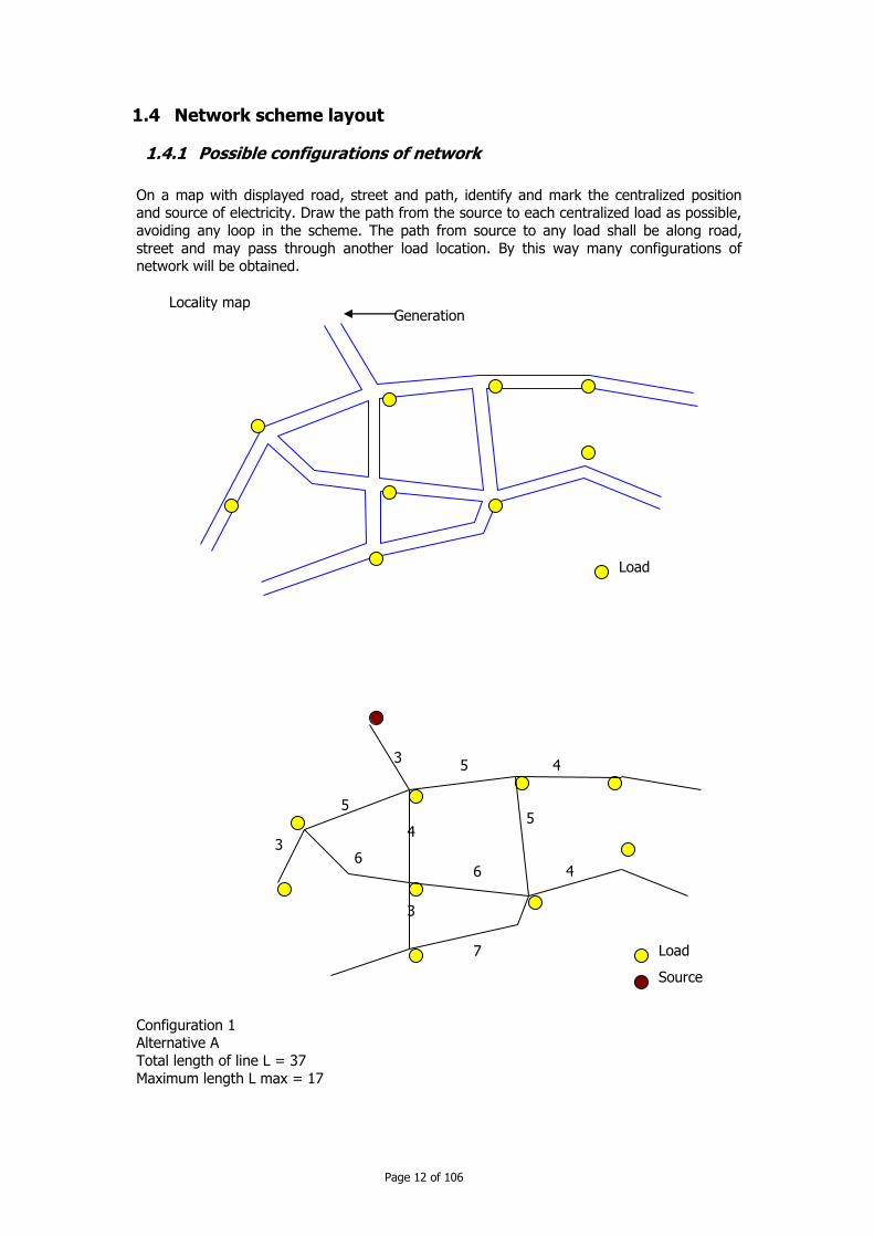
1.4 Network scheme layout
1.4.1 Possible configurations of network
On a map with displayed road, street and path, identify and mark the centralized position and source of electricity. Draw the path from the source to each centralized load as possible,
avoiding any loop in the scheme. The path from source to any load shall be along road,
street and may pass through another load location. By this way many configurations of network will be obtained.
Configuration 1 Alternative A
Total length of line L = 37
Maximum length L max = 17
3 4 5
Load
Source
4 5
6
7
4
5
6
3
3
Locality map Generation
Load
Page 13 of 106
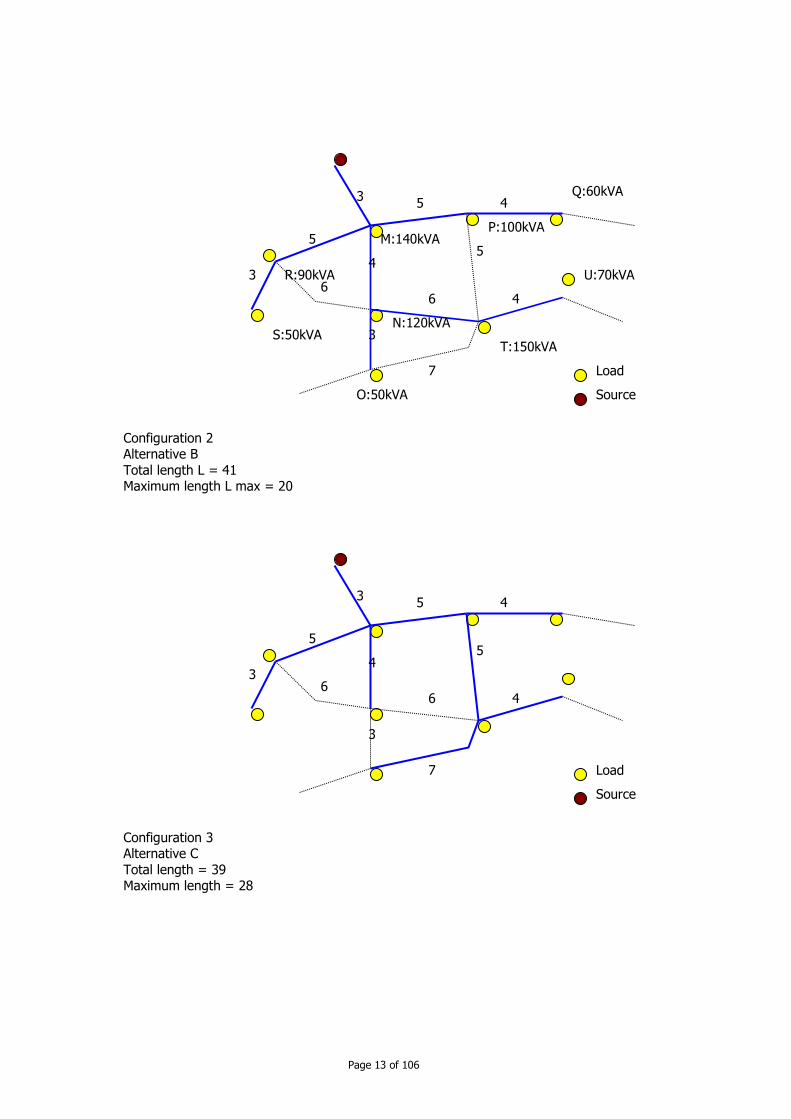
Configuration 2 Alternative B
Total length L = 41 Maximum length L max = 20
Configuration 3 Alternative C
Total length = 39 Maximum length = 28
3 4 5
Load
Source
4 5
6
7
4
5
6
3
3
3 4 5
Load
Source
4 5
6
7
4
5
6
3
3
M:140kVA P:100kVA
Q:60kVA
T:150kVA
U:70kVA
O:50kVA
N:120kVA
R:90kVA
S:50kVA
Page 14 of 106
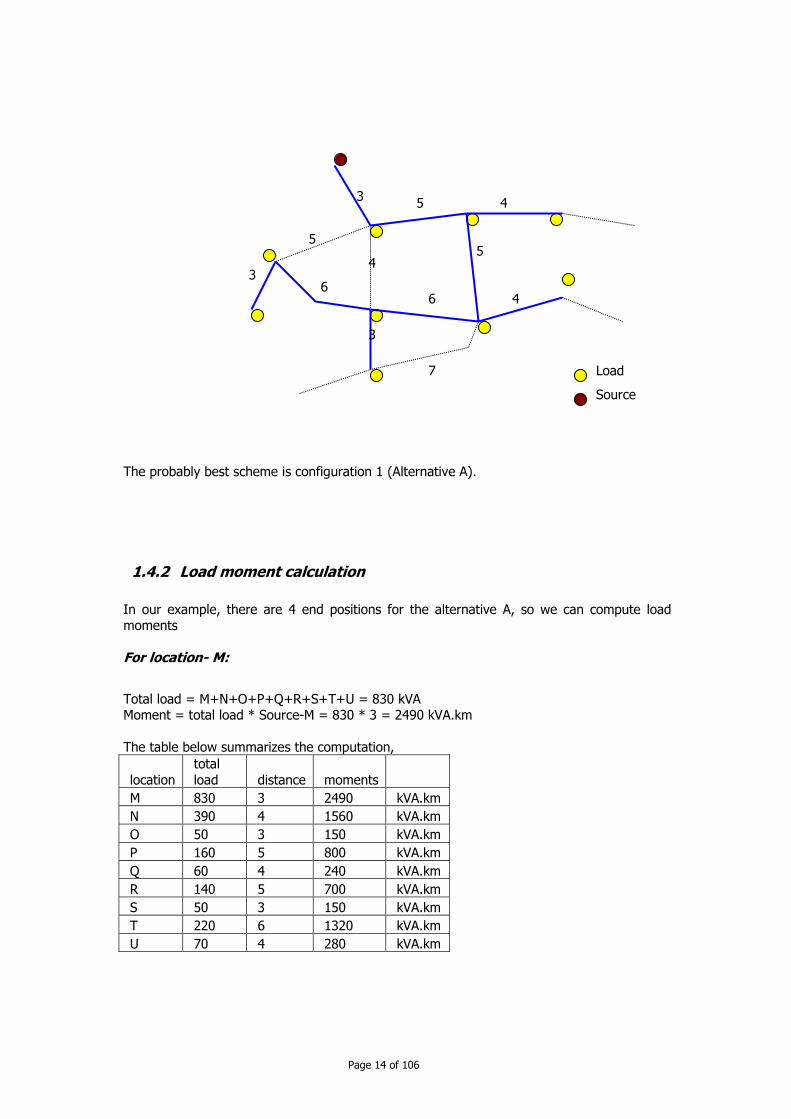
The probably best scheme is configuration 1 (Alternative A).
1.4.2 Load moment calculation
In our example, there are 4 end positions for the alternative A, so we can compute load moments
For location- M:
Total load = M+N+O+P+Q+R+S+T+U = 830 kVA Moment = total load * Source-M = 830 * 3 = 2490 kVA.km
The table below summarizes the computation,
location
total
load distance moments
M 830 3 2490 kVA.km
N 390 4 1560 kVA.km
O 50 3 150 kVA.km
P 160 5 800 kVA.km
Q 60 4 240 kVA.km
R 140 5 700 kVA.km
S 50 3 150 kVA.km
T 220 6 1320 kVA.km
U 70 4 280 kVA.km
3 4 5
Load
Source
4 5
6
7
4
5
6
3
3

Page 15 of 106
For line Source-S:
Load moments = moment M + moment R + moment S = 2490 + 700 + 150 = 3340 kVA.km
For line source-O: moment = 4200 kVA.km
For line source-Q: moment = 3530 kVA.km
For line source-U: moment = 5650 kVA.km
T = 150kVA N' = N+O =170kVA M' = M + R + S + P + Q = 440 kVA
Moment = M'*3 + N'*(3+4) + T*(3+4+6) + U*(3+4+6+4) = 440x3+170x7+170x13+70x17 = 5650 kVA.km
U = 70kVA
Q = 50kVA P = 100kVA M' = M + N + O + R + S
+ T + U = 680 kVA
Moment = M'*3 + P*(3+5) + Q*(3+5+4) = 680x3+100x8+50x12 = 3530
O = 50kVA N' =N+T+U = 340kVA M' = M + P + Q + R + S = 440 kVA
Moment = M'*3 + N'*(3+4) + O*(3+4+3) = 440x3+340x7+50x10 = 4200
S = 50kVA R = 90kVA M' = M + N + O + P + Q + T + U = 690 kVA
Moment = M'*3 + R*(3+5) + S*(3+5+3) = 690x3+90x8+50x11 = 3170

Page 16 of 106
1.4.3 Selection of conductors by voltage drop criteria
The conductor AAC and ACSR (see par 2.3 Conductors) can be chosen for the MV overhead network. Requirement on voltage drop: for example 5% at the end of line.
To determine cross section of conductor, we should select an appropriate value from the below table.
For power factor = 0.8
Cross section mm2 Moment for voltage drop 5% kW.km
35 50
70 95
120
150
20,000 26,000
32,000 39,500
42,500
47,500
In above example, maximum moment in line Source-U is 5650 kVA.km or 4520kW.km if power factor is equal to 0.8. So the cross section for this line is 150mm2.
Recommendations:
You should choose only about 2 cross sections, and if possible only one cross section.
The main line may be double circuit, and this line will be built in two stages; for example: first for the period of first seven years, only one circuit and then after seven years, we build
the second circuit.
1.4.4 Verification of the conductors by power loss
The MV network should be designed in the way that the power loss is minimized. The loss in
distribution network in practice may be about or less than 10%. This loss is composed of (1)
loss on MV network; (2) loss in transformer post; and (3) loss in LV network. For example the loss in MV network is about 2%; that in transformer is about 2.5% and that in LV
network is about 6.5%. After determining the conductor cross section by voltage drop, the power loss is calculated
for maximum and minimum service. Sometime the cross section shall be increased to satisfy
the power loss requirement.
1.5 MV network scheme
When designing a MV network scheme, we should consider of:
Reliability of the scheme,
Easy operation and maintenance of the network.
1.5.1 Steps in designing the scheme
To draw functioning scheme of the network.
To design the connection point to satisfy the requirement of each node. To design the protection of main line.
For economic reason, the protective device may be fuse cutout. For convenience in operation, the load breaker switch is the preferred one.
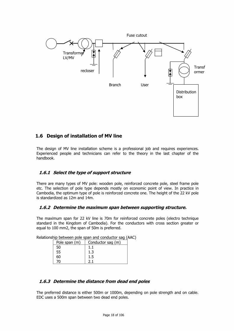
Example of functioning scheme
Page 17 of 106
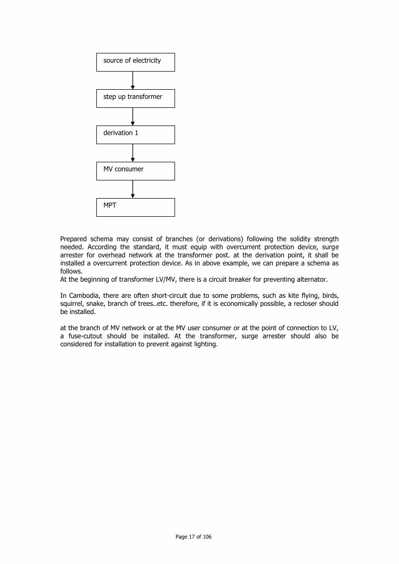
Prepared schema may consist of branches (or derivations) following the solidity strength needed. According the standard, it must equip with overcurrent protection device, surge
arrester for overhead network at the transformer post. at the derivation point, it shall be installed a overcurrent protection device. As in above example, we can prepare a schema as
follows.
At the beginning of transformer LV/MV, there is a circuit breaker for preventing alternator.
In Cambodia, there are often short-circuit due to some problems, such as kite flying, birds, squirrel, snake, branch of trees..etc. therefore, if it is economically possible, a recloser should
be installed.
at the branch of MV network or at the MV user consumer or at the point of connection to LV,
a fuse-cutout should be installed. At the transformer, surge arrester should also be considered for installation to prevent against lighting.
source of electricity
step up transformer
derivation 1
MV consumer
MPT
Page 18 of 106
1.6 Design of installation of MV line
The design of MV line installation scheme is a professional job and requires experiences.
Experienced people and technicians can refer to the theory in the last chapter of the handbook.
1.6.1 Select the type of support structure
There are many types of MV pole: wooden pole, reinforced concrete pole, steel frame pole etc. The selection of pole type depends mostly on economic point of view. In practice in
Cambodia, the optimum type of pole is reinforced concrete one. The height of the 22 kV pole
is standardized as 12m and 14m.
1.6.2 Determine the maximum span between supporting structure.
The maximum span for 22 kV line is 70m for reinforced concrete poles (electro technique
standard in the Kingdom of Cambodia). For the conductors with cross section greater or
equal to 100 mm2, the span of 50m is preferred.
Relationship between pole span and conductor sag (AAC)
Pole span (m) Conductor sag (m)
50
55 60
70
1.1
1.3 1.5
2.1
1.6.3 Determine the distance from dead end poles
The preferred distance is either 500m or 1000m, depending on pole strength and on cable. EDC uses a 500m span between two dead end poles.
Fuse cutout
User Branch
Distribution box
Transformer
Transformer
LV/MV
recloser

Page 19 of 106
1.6.4 Map of network
Along the line trace, we can identify pole location and pole type. We can select the
appropriate strength of pole depending on type and its location on the trace.
On the map, draw the 22 kV line trace on it, mark the pole position and the type of pole. All poles should be enumerated. Special location should be marked by special symbol (e.g. PMT,
protective device, etc.).
Page 20 of 106
CChhaapptteerr 22:: PPrreeppaarraattiioonn ffoorr ccoonnssttrruuccttiioonn ooff MMVV
nneettwwoorrkkss
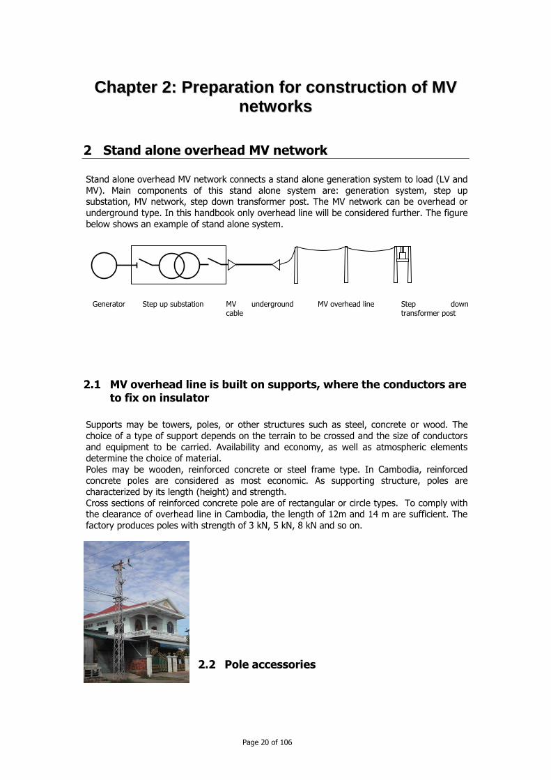
2 Stand alone overhead MV network
Stand alone overhead MV network connects a stand alone generation system to load (LV and
MV). Main components of this stand alone system are: generation system, step up substation, MV network, step down transformer post. The MV network can be overhead or
underground type. In this handbook only overhead line will be considered further. The figure
below shows an example of stand alone system.
2.1 MV overhead line is built on supports, where the conductors are to fix on insulator
Supports may be towers, poles, or other structures such as steel, concrete or wood. The
choice of a type of support depends on the terrain to be crossed and the size of conductors
and equipment to be carried. Availability and economy, as well as atmospheric elements determine the choice of material.
Poles may be wooden, reinforced concrete or steel frame type. In Cambodia, reinforced concrete poles are considered as most economic. As supporting structure, poles are
characterized by its length (height) and strength.
Cross sections of reinforced concrete pole are of rectangular or circle types. To comply with the clearance of overhead line in Cambodia, the length of 12m and 14 m are sufficient. The
factory produces poles with strength of 3 kN, 5 kN, 8 kN and so on.
2.2 Pole accessories
Generator Step up substation MV underground
cable
MV overhead line Step down
transformer post

Page 21 of 106
In Cambodia, the crossarms are usually made of galvanized steel. The usual cross-sectional dimensions for distribution crossarms are 0.09m by 0.1m; their length depending on the
number and spacing of pins. Heavier arms of varying lengths are used for special purposes, usually holding the heavier transmission conductors and insulators.
When a heavy loading is usually encountered, as at corner or junction poles, double arms,
that is, one on each side of the pole, may be required.
Note: For ABC type cable, the fixing structures are very simplified.
2.2.1 Insulators
Line conductors are electrically insulated from each other as well as from pole by non-
conductors which are called insulators.
There are two type of insulator: pin insulator and suspension insulator.
To determine whether or not an insulator can be used, both its mechanical strength and
electrical properties must be considered. Two practical insulator materials are porcelain and glass – Porcelain can withstand heavy loading in compression, but tears apart easily under
tension, that is, when pulled apart. In using a porcelain insulator, therefore, care must be taken to make the forces acting on its compress and not pull apart. The same is generally
true of glass. Although glass insulators are good for lower voltage application, porcelain insulators are
much more widely used because they are more practical.
Pin insulators are fixed to crossarm by pin poles. The pole pins are used to attach to the croosarms. They are used to hold pin type insulators. Note that they are threaded so that
the insulator can be securely screwed on.
2.2.2 Pin spacing

Page 22 of 106
The spacing of the pins on the crossarms must be such as to provide air space between
conductors to prevent electric current from jumping or flashing over from one conductor to another. Also, sufficient spacing is necessary to prevent contact between the wires at
locations between poles when the wires sway in the wind. In addition, enough spacing must be provided to enable workers climbing through the wires to work safety. The spacing on a
standard threepin arm is 0.7m, (so to say around 2.2m long arm for MV line).
2.2.3 Pin type insulators
Insulators, in compression, supporting conductors may be classified as pin type. The pin type
insulator is designed to be mounted on a pin which in turn is installed on the cross arm of
the pole. The insulator is screwed on the pin and electrical conductor is mounted on the insulator.
This pin type insulator is applicable for rural and urban distribution circuits, and it is usually
constructed as one of solid piece of porcelain or glass.
2.2.4 Suspension type insulator
2.3 Conductors
Most conductors are aluminium or copper. We use aluminium for almost all new overhead line installations because aluminium is lighter and less expensive than copper for a given
current carrying capability. But aluminium can corrode quickly through electrical contact with
Page 23 of 106
copper or steel. To connect it to copper bar or conductor a bimetal connector shall be used
to prevent corrosion of aluminium conductor.
There are many types of conductor in usage: AAC (all aluminium cable) has highest conductivity-to-weight ratio. AAC has enough strength
for usage in urban or suburban area
ACSR (aluminium conductor steel reinforced) has high mechanical strength-to-weight ratio. ACSR has about twice the breaking strength of AAC. ACSR is used in the area where you
have often to cut or trim tree, or there are strong wind such as in rural area. AAAC (all aluminium alloy conductor) has strength and equivalent capabilities of AAC or
ACSR. It is used for coastal area where ACSR is prohibited. ACAR (aluminium conductor, alloy reinforced)
ABC aerial bundle cable (for MV). ABC cable should use in the area where the safety
clearance is difficult to be ensured, for example in urban area, where there are narrow street, tourist site
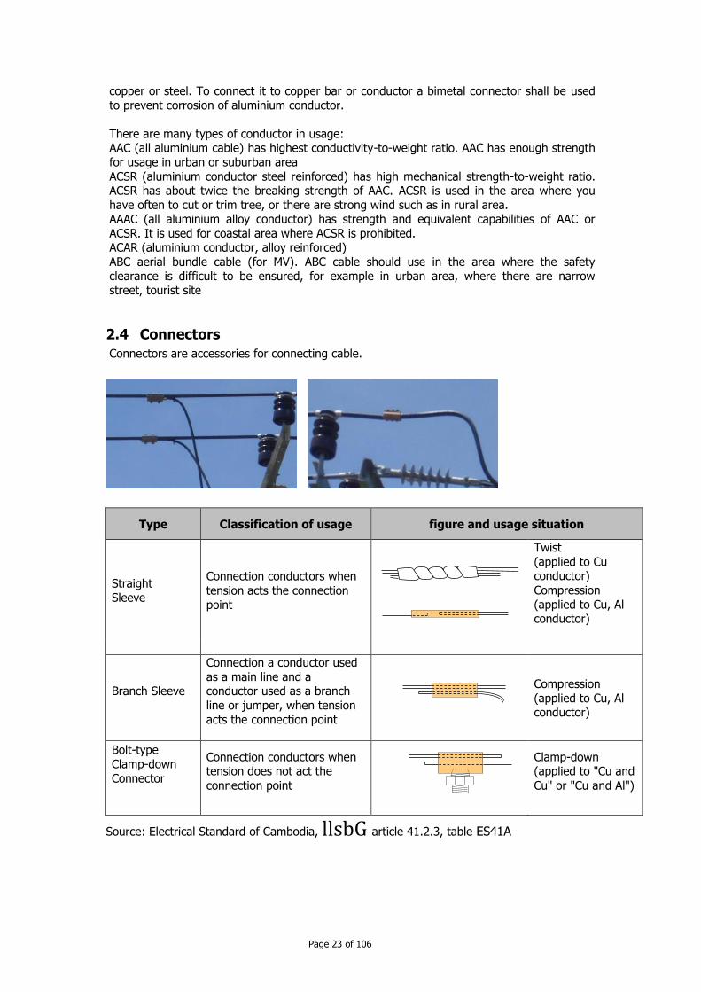
2.4 Connectors
Connectors are accessories for connecting cable.
Type Classification of usage figure and usage situation
Straight Sleeve
Connection conductors when
tension acts the connection
point
Twist
(applied to Cu conductor)
Compression
(applied to Cu, Al conductor)
Branch Sleeve
Connection a conductor used
as a main line and a conductor used as a branch
line or jumper, when tension
acts the connection point
Compression
(applied to Cu, Al conductor)
Bolt-type
Clamp-down
Connector
Connection conductors when tension does not act the
connection point
Clamp-down (applied to "Cu and
Cu" or "Cu and Al")
Source: Electrical Standard of Cambodia, llsbG article 41.2.3, table ES41A
Page 24 of 106
2.5 Post of Transformers
They are electric static machines to transfer electrical energy converting from one voltage to another voltage.
In MV network distribution, a transformer transferring
energy from LV to MV is called step up transformer, and from MV to LV is called step down transformer.
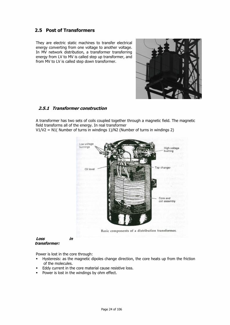
2.5.1 Transformer construction
A transformer has two sets of coils coupled together through a magnetic field. The magnetic field transforms all of the energy. In real transformer
V1/V2 = N1( Number of turns in windings 1)/N2 (Number of turns in windings 2)
Loss in transformer:
Power is lost in the core through:
Hysteresis: as the magnetic dipoles change direction, the core heats up from the friction
of the molecules. Eddy current in the core material cause resistive loss.
Power is lost in the windings by ohm effect.
Page 25 of 106
Distribution transformer:
Distribution transformer has power range from a few kVA to a few MVA. This transformer has function to convert primary voltage to low voltage that customers use.
Size: Transformer size sometime means the rated power in kVA. Standard rated power may be for single phase transformer 5, 10, 15, 25, 37.5, 50, 75, 100, 167, 250, 333,
500 (kVA). For three phase transformer the rated power may be 30, 45, 75, 112.5, 250,
300, 500 kVA.
Through fault capability of distribution transformer: for single phase: 40 pu for 5-25 kVA, 35 pu for 37.5-110 kVA and 25 pu for 167-500 kVA.
for three phase: 40 pu for 15-75 kVA, 35 pu for 112.5-300 kVA and 25 pu for 500 kVA.
Completely self-protected transformers (CSP):
It is used in single phase distribution transformer with some built-in features: tank mounted arrester, internal weak-link fuse and secondary breaker.
Three phase transformer:
Primary system: on primary side of three phase distribution transformer, utilities have a
choice between grounded and ungrounded winding connections. In Cambodia we use ungrounded winding connection.
Ungrounded primary: there are delta and floating wye primary connections. These
connections are suitable for ungrounded and grounded distribution systems. Grounded primary: there is only grounded wye connection. It is suitable on four-wire
grounded systems.
Secondary system:
Grounded wye secondary (used in Cambodia)
Delta secondary for three wire ungrounded services.
Note: Industrial facilities prefer an ungrounded system, because the system can be operated with line-to-ground faults.
The scheme Delta-Grounded Wye are used in distribution network in Cambodia. Advantages of such system are:
supply 3 wire or 4-wire system supply grounded-wye service, 400 volts
does not supply ungrounded service Ground faults: block zero sequence so upstream ground relays are isolated from line-to-
ground faults on the secondary of the customer transformer.
Harmonics: isolates the primary from zero-sequence harmonics created on the secondary.
No primary ground service Secondary ground source
No tank heating: no zero-sequence flux in the transformer's core.
Ferroresonance: highly susceptible.
Loading conditions:
Page 26 of 106
Transformer can deliver its rated kVA without exceeding temperature rise limits when is
under some conditions: Secondary voltage and the voltage/frequency do not exceed 105% of ratings.
Power factor greater or equal 80% Frequency not less than 95% of rating
Losses:
Distribution transformers account for about 30% of transmission and distribution loss. There are 2 main contributors to losses: No load loss about 85% and load loss about 15%.
No load losses are the continuous losses of a transformer, regardless of load (from 0.15 to 0.4% of transformer power);
Load loss (copper or wire losses) are from current through the transformer's windings, generating heat through the winding resistance as I2R.
Inrush:
When a transformer is switched on, the transformer may draw inrush current from the system due to core magnetisation being out of sync with the voltage. The inrush current
may approach short-circuit levels (about 40 times the transformer's full load current). Inrush may cause fuses, reclosers or relays to falsely operate.
Some voltage disturbances cause inrush in transformer:
Voltage sags: when there is recovery from voltage sag from a nearby fault, the sudden rise in voltage can drive a transformer into saturation.
Symmetrical inrush: Energizing a transformer can cause a nearby transformer to also draw inrush.
Lightning. A flash to the line near the transformer can push the transformer into
saturation.
2.6 Protective devices
A distribution system is exposed to overcurrent, overvoltage, and open circuit conditions.
Protective equipment is placed to limit and isolate the faults so that the remainder of the
system is not affected. At a distritbution substation, there are normally high-voltage fuses or a circuit breaker on the
high-voltage side of the substation transformer and circuit breaker or reclosers on each distribution feeder or the low-voltage side.
Page 27 of 106
Circuit Interrupters, including circuit breakers, fuse and recloser.
The devices interrupt fault current during a zero-crossing. The interrupter creates an arc.
Example: Fuse creates an arc when the fuse element melts. Circuit breaker or recloser does it when the contacts mechanically separate.
After the arc is created, the dielectric strength across the arc is increased so that the arc
clears at the current zero. There are 2 types of MV circuit interrupters: Interrupter such as disconnect switch, load interrupter is installed to provide operating
capability. It can operate with a load-break tool or can interrupt load current or cannot interrupt any load current. But none of this type can interrupt fault current.
Interrupter such as a circuit breaker, a recloser, a sectionalizer or a fused cutout is
installed to provide circuit protection.
Circuit breaker
Circuit breakers are often used in substation on the bus and on each feeder. Circuit breakers
are tripped with external relays. They are installed to protect generators, transformers, sub-transmission lines and distribution lines.
Circuit breaker relay
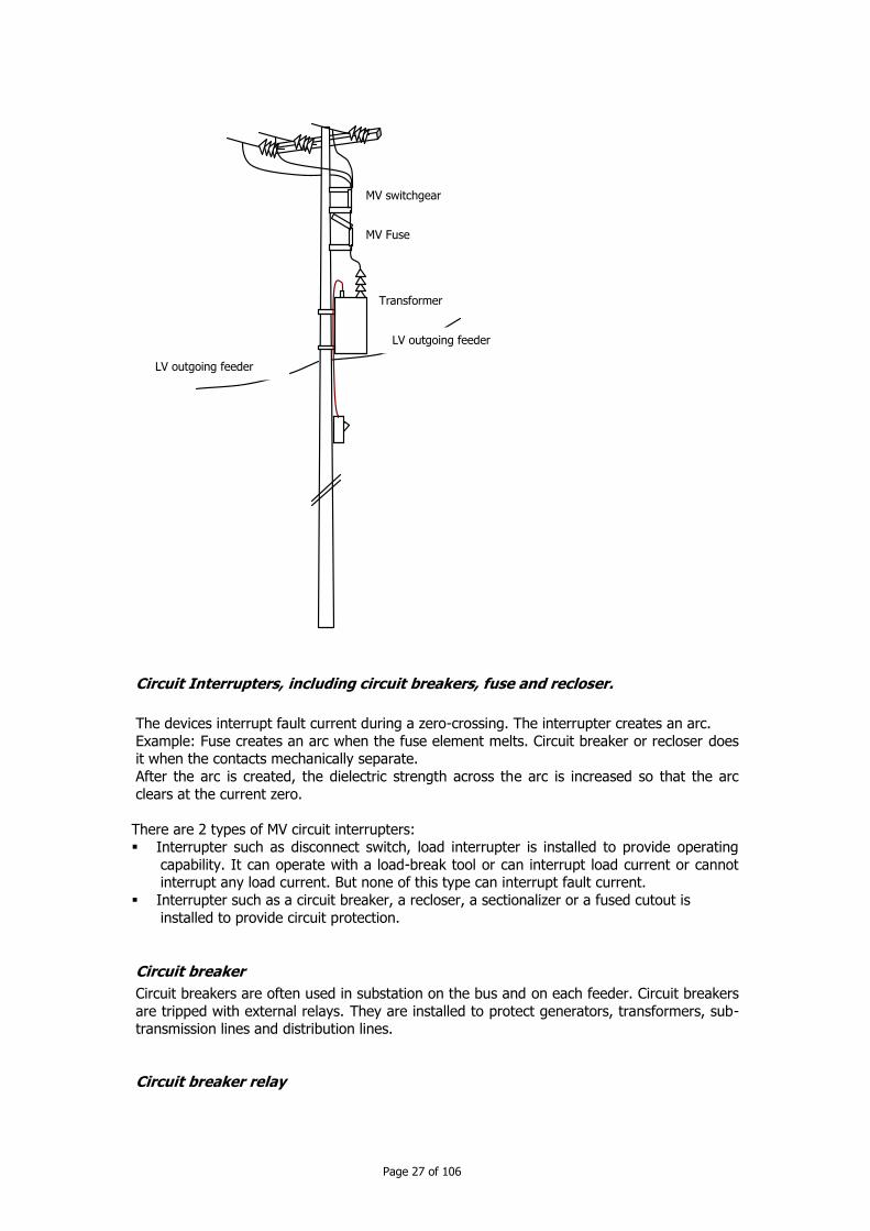
MV switchgear
MV Fuse
Transformer
LV outgoing feeder
LV outgoing feeder

Page 28 of 106
Distribution circuits are almost always protected by overcurrent relays that inverse time
overcurrent characteristics.
Main type of relays: electromagnetic relays, static relays (analog electronic circuit) and digital relays (based on micro processor component).
Examples of some of the relays that can be installed to protect a circuit are listed: An overcurrent relay detects current when its exceeds some limits
a thermal relay detects an abnormal rise in the temperature of a generator or transformer.
Expulsion fuses
Fuses are low-cost interrupters that are easily replaced.
Concept: a fuse element made of tin or silver melts under high current. In a fuse tube, after the fuse element melts, an arc remains. The arc, which has considerable energy, can cause a
rapid pressure build up. The pressure forces much of ionized gas out of the bottom of the
cutout. By this way the electric strength increases with the help of extreme pressure, arc stretching and turbulence of gas.
Fuse cutout
Some varieties of cutout are built with a removable fuse holder. The holder is placed in a
cutout with a porcelain bushing type support. These cutouts do not have load break capacity. If the cutout is opened under load, an arc can drew out and will not clear.
When the fuse is in the fuse holder melts, it breaks a mechanical link, which causes the fuse
holder to drop open. It provides overcurrent protection and will isolate faultry equipment and circuits automatically.
Page 29 of 106
Whe a cutout is opened with a switch stick, the cutout operated as a regular disconnect
switch with no arc-extinguish equipment other than the air gap between the switch terminals. Normally a load-break tool should be used when interrupting load current.
Link-break fused cutout is a cutout that can interrupt load. A link-break hook is pulled down
with a switch stick to break the fuse link and safely extinguish any arcing inside the fuse
chamber. If a cutout is closed in on a faulted circuit, it is important not to immediately open the cutout.
Let the fuse and fuse holder extinguish the arc.
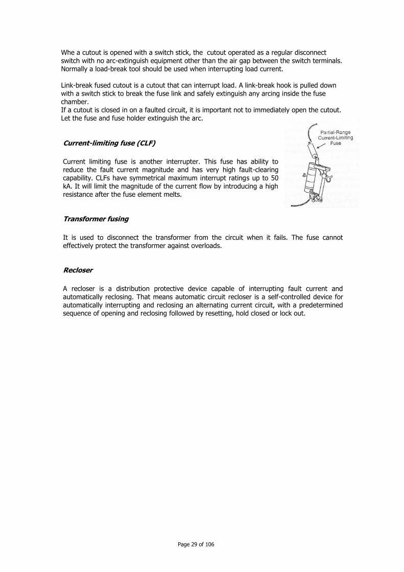
Current-limiting fuse (CLF)
Current limiting fuse is another interrupter. This fuse has ability to reduce the fault current magnitude and has very high fault-clearing
capability. CLFs have symmetrical maximum interrupt ratings up to 50
kA. It will limit the magnitude of the current flow by introducing a high resistance after the fuse element melts.
Transformer fusing
It is used to disconnect the transformer from the circuit when it fails. The fuse cannot effectively protect the transformer against overloads.
Recloser
A recloser is a distribution protective device capable of interrupting fault current and
automatically reclosing. That means automatic circuit recloser is a self-controlled device for
automatically interrupting and reclosing an alternating current circuit, with a predetermined sequence of opening and reclosing followed by resetting, hold closed or lock out.

Page 30 of 106
Example of simple sequence of opening and reclosing in a recloser
In operation
Interrupt the circuit until staff intervention
Fault current?
Interrupt circuit and wait t seconds
Reclose: connect the circuit
Fault current?
NO

Page 31 of 106
2.7 Surge arrestors
A surge arrester is a device to arrest the surge of
lightning. Surge arrester has metal-oxide block.
Under normal voltage, a metal-oxide surge arrester is almost an open circuit. When there is an overvoltage,
the metal-oxide block responds almost instantly by dropping it current impedance to a few ohms only.
After the surge is done (no more overvoltage) the
metal-oxide is immediately returns to its normal high impedance.
2.8 Metering system equipment
Current transformer: a device to transform a big current to a current in the range of 0..5
A that can pass through measurement instrument (e.g. meter)
Voltage transformer: a transformer for adapting the high voltage to the rated voltage of
meter.
Now digital meter is widely used in MV network in Cambodia.
The MV meter is also a type of meter used for LV system, and is connected to the main lines via current and voltage transformers as shown in the figure below.
The meter must be class 1 in accordance with IEC.
Current transformer plays a role of: Convert a big current to a current in the range of 1….5A
Isolate the measurement circuit from MV line for safety.

Page 32 of 106
In general, the meter is often found with the range of 5A in Cambodia. Therefore, the secondary current is also 5A.
Voltage transformer plays a role of:
Convert a MV voltage to LV voltage (range of 100 or 110V) to allow meter function.
Isolate the measurement circuit from MV for safety.
Page 33 of 106
CChhaapptteerr 33 RRiisskk aanndd ssaaffeettyy iissssuueess
3 Risk and safety issues
3.1 Environment concern
Production activities can have negative impacts on environment. Installation of overhead line should be conducted in such a way to minimize bad impacts on environment. Big impact may
be from cutting trees and flora, trimming tree, loss of cultivative soil, bad influence of electromagnetic field on human health.
Overhead line almost damages some interest from agriculture. So overhead line should be
laid along a road, path or on border of land use. Luckily the construction of 22 kV line
sometime has minimum influence on agriculture.
Strictly follow the safety rule (rule about clearance). See Electrical Technical Standard in Kingdom of Cambodia. In planning, the layout of overhead line should be scheduled for a
period with less economic activities.
In transporting material like pole, conductors and construction materials, avoid as possible
damaging tree, land surface, road surface. Use truck with lifting hoist with high capacity. Lay the pole parallel to road so that the pole could not obstruct the traffic and cause accident.
The bad influence of electromagnetic field can be reduced by putting the line at s sufficient height (see rule about clearance). The electric field intensity should less than 15 kV/m in no-
population area, 5 kV/m in town and 10 kV/m on the road.
To reserve the landscape, the pole should be acceptable in view point of aesthetic. Cylindrical pole is a good example.
Do not allow easy to burn or explodable material near the line trace to prevent any fire case, especially in dry season.
3.2 Organization for safety
To prevent professional sickness, traumas on workers, some rules must be respected:
Before sending a worker to install overhead line, give him necessary information, rule, measure for remain safety.
Each team shall have first-aid manual, kit and materials.
When installation work is conducted far from hospital, health centre, we should reserve a special transport for case of accident.
Do not allow a worker to execute task alone without survey
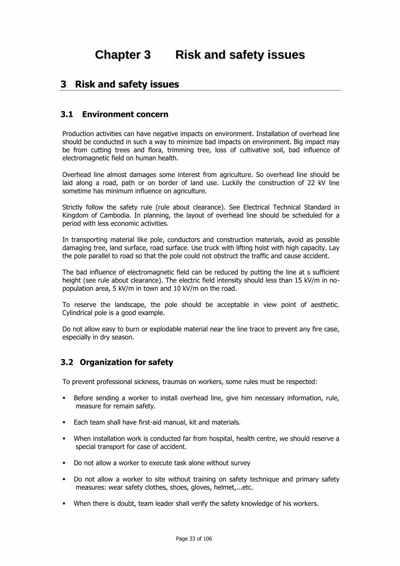
Do not allow a worker to site without training on safety technique and primary safety measures: wear safety clothes, shoes, gloves, helmet,...etc.
When there is doubt, team leader shall verify the safety knowledge of his workers.

Page 34 of 106
Do not allow boys or girls less than 18 years old near by the installation area.
3.3 Safety measures
3.3.1 Cutting tree:
Two teams shall be separated by a distance larger than 50 m.
Cut only a tree in one time.
If necessary trim the tree branch as much as possible Do not work when there are strong wind, rain or storm.
Do not stand in the corner, where the tree should fall down. Respect the safety manual when used special cutting machine.
3.3.2 Earth works:
Respect the rule by excavating earth slowly, with small amount a time to avoid damaging underground installations.
Excavated soil shall be put at least 0.5 m far from the hole mouth.
Take an appropriate measure to prevent landslide. Do not stand inside the area of the excavator arm action
The hole shall be covered and marked to prevent people fall down.
3.3.3 Foundation:
If a worker is inside the hole, do not allow people stand near the hole mouth (at least 1 m
far from the mouth). A worker can approach the hole mouth by stepping or standing on a
wooden bridge. When put the concrete mix, do not allow concrete mix touch the hole wall when falling.
3.3.4 Using lifting hoist:
Check the strength of cable or trolley and the correct work of lifting mechanism.
Do not allow overweighting the hoist mechanism (over lifting capacity) Respect the meaning of control signal
Allow only one direction of displacement at one time: vertically, horizontally (turning at some angle and at low speed).
Do not allow people stand under the load when lifting.
3.3.5 Installing pole:
Workers shall know their role and responsibility.
kþars<an [ehormat;reNþA)an1m

Page 35 of 106
One worker will give control signal, so do not allow him to do other task, when
controlling. Check every time necessary item before the execution (enlacing the pole, hook the pole,
roller mechanism, cable etc.) Pole shall be installed completely. If the installation can not be finished, the pole shall be
lay down back to the ground.
Allow to climb up the pole only when the pole can stand strongly alone.
3.3.6 Lifting, handling materials
Lighting the work area, following the norm of lighting.
Worker shall have self-confidence Lifting, handling pole shall be done under the control of a responsible.
Pole shall be lay on the ground completely and parallel to the road or path.
3.3.7 Handling conductor
Avoid hooking with clothes, conductor rolls fall down to ground The conductor rolls shall be put at horizontally smooth and reliable surface
Turning the conductor rolls in counter direction of the windings When stretch the conductor, turn the conductor rolls in the windings direction.
3.3.8 Pulling conductor
Pulling smoothly. Avoid pulling abruptly the conductor.
Check stability of conductor rolls Do not make ring for pulling.
Do not pull the conductor to the top of hill, The conductor should be pulled from the hill
top down. When there is obstacle, to liquidate this obstacle, stand at the side where the conductor
will not be moved. Do not allow children less than 18 years old climb the pole.
To climb the pole, worker shall use appropriate tool and safety tool such as climbing ring,
scale, safety belt etc. Check the pole stability before climbing.
Bring a light and reliable cable for lifting tool when necessary. Use pulley to bring necessary material to top of the pole.
Do not allow people stand near pole while people work at the top of pole.

Page 36 of 106
Safety when installing conductor:
Conductor of overhead lines may be bare or covered. Such conductors, located in trees, or
adjacent to structures where they may come into contact occasionally, may be covered with high density polyethylene or other plastic material resistant to abrasion. This covering is
generally not sufficient to withstand the rated voltage at which the line is operating, so these conductors must be mounted on insulators any way. The purpose of covering is mainly to
protect the wire from mechanical damage. The wire should be treated as though they were
bare.
If installation of conductor is done in the area where there is not electricity, workers shall wear safety tools: helmet, goggles, clothes with tight sleeves and trouser legs, no ring on
fingers, no bracelet on arm, no collar on neck, safety shoes.
If installation is conducted in the area where there is electricity supply, workers shall wear
over safety tools some special protective tools if necessary. For example wear protective gloves over rubber gloves.
The conductor to be installed shall be connected to earth.
Safety when installing distribution transformer:
While working; protect yourself; lift and move transformer with care and mount
transformer securely. Observe all safety practices and procedure regulations established.
Wear all protective gear and clothing (boots, helmet, gloves, mask, goggles, safety glasses..) for safety job.
Before moving the transformer, check the total weight of equipment (see nameplate for example) and check the conditions and capacity of all lifting and hoisting equipment.
Do not use worn, frayed or damaged hooks, cables, or slings.
Do not use fork lift or cranes with load capacity less than the weight of the transformer. Do not drop the transformer from truck.
The transformer must be securely fastened to the pole.
When making connection of transformer to network:
Make sure multiple voltage switches and tap changes are in the proper position. Make sure the tank is grounded properly before doing any other works.
Clean all bushings, terminals and all connection points before making system connection. Make sure the insulating fluid is at the proper level before the transformer is energized.
Safety tools and instruments:
Helmet Gloves
Clothes
Shoes Insulated and indicator rod
Standing at this point
Problems, such as small trees, rock, etc Direction after problem solved

Page 37 of 106
Grounding conductors and temporary earthing system
3.4 Safety issues in operation
3.4.1 Step potentials, touch potentials
During ground fault, all the ground current returns to the substation transformer through
the earth. It can create significant voltage gradient along the ground and between the ground and conducting objects.
Touch potential is considered a hand-to-foot or hand-to-hand contact. Step potential
creates a path through the legs from one foot to another. Under normal condition, these voltages are not dangerous but can cause annoying
shocks and concerns in farms (slay voltage). But step and touch voltage potentials during faults are more dangerous.
When you feel that you are in the electric field of ground fault:
Stand by uniting the 2 legs and ask your college to shut down the circuit if possible Do not run (avoid bid step voltage, especially when you fall down)
Do not touch any object around you with bare and non insulated arms. Walk by very small step, not lifting your leg from the ground and take care not to fall
down.
3.4.2 Slay voltage
Slay voltage is a touch voltage that end-users experience. Possibly causes of slay voltage are:
improper facility grounding and bonding
may on secondary system (larger neutral, poor neutral connections...) failed equipment insulation ( a failure to a bonding frame)
Utility side to slay voltage includes:
Balancing (reduces earth return current, so reduce neutral to earth voltage) Single phase lines: converting single phase sections to 2 or 3 phases to reduce the
neutral to earth voltage.
Neutral: upgrade neutral size to create low impedance path for earth-return current. Capacitor banks: check item for blown fuses. If a grounded-wye capacitor has a blown
fuse, the unbalance can create excessive neutral current.
3.5 Safety in Maintenance
Procedure should be followed when maintaining the system:
Note that working only on deenergized circuit.
The responsible person, before sending team to do maintenance work, shall: Describe clearly the task and the specification of location to do maintenance.
give special instructions if necessary Check list of necessary tool and additional tools, safety labels etc.
If necessary verify the safety knowledge of the team staff. switch off the circuit at maintenance place and put appropriate label on switch ("People
working");
check the voltage on the place and ground the circuit Put the label "work here", "pass by here" etc.

Page 38 of 106
Allow people to do their job.
3.5.1 Tree contact
Tree contact causes possibly
dangerous shocking hazard. If a tree is on contact with an
energized phase conductor, it
may create a touch potential hazard near the ground. The
tree will not draw enough current to operate a fuse or
other protective devices. But it may create significant
touch potentials.
In that case, some measures should be considered: educate the public on dangers of cutting trees in the vicinity of power lines
trim tree away from power lines
train tree trimming crews and ground support crews properly use covered wire instead of bare wire.
3.5.2 Protective grounding
Repair, maintenance and installation shall be done with the circuit deenergized. During
deenergized work, protective grounds tie the phase conductors to a ground point, in order
to: Prevent the case that circuit accidentally energized
Protect against voltages from magnetic or capacitive coupling and backfeed through transformer or capacitor banks
So some measures have to be considered by the team when doing repair and maintenance work:
1) Test the line voltage before installing jumpers 2) Team work until the team finishes the work
3) Ensure that everyone is clear of the work site 4) Remove the protective grounds
Note: the protective grounding set should be tested periodically.
3.5.3 Procedure to implement the work with safety
1. Remember that safety while carrying out the work should follow the following
procedure even though those works are small.
1. Meeting before starting work:
All concerning people must participate the meeting and then follow the principle
below:
a. Work plan b. Schedule
c. role of each staff d. safety tool
e. check all accessories to be used
f. inform concerning people

Page 39 of 106
2. Preparing for staring work
Work on network: disconnect the circuit breaker. a. Put signal near circuit breaker: “do not switch on the electricity supply while
working” must have a permanent guard.
b. Lock the circuit breaker in case of electricity supply disconnection. Check the voltage using measurement tool for MV/LV voltage.
Voltage Measure tool
Measurement tool of voltage of 1 kV
2. Install the grounding system, all phase conductors must be interconnected in case of short-circuit, so it is connected to the ground for:
a. Finally confirming that one working on one circuit is correctly done with safety.
b. Obtaining prevention from electrical shock to be generated by return-current
due to mal working made by operator, touching with neighboring circuit, lighting…
c. Obtaining prevention from induction: we need the grounding system to prevent from induction on 2 types: static induction will generate voltage in
the circuit and magnetic induction will generate current flow within the
conductor connected to the ground.
Connected to the ground while working
To protect those who come inside the working place, the warning board must be
installed
Source
Working place
Page 40 of 106
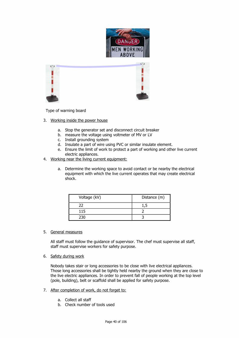
Type of warning board
3. Working inside the power house
a. Stop the generator set and disconnect circuit breaker b. measure the voltage using voltmeter of MV or LV
c. Install grounding system d. Insulate a part of wire using PVC or similar insulate element.
e. Ensure the limit of work to protect a part of working and other live current
electric appliances. 4. Working near the living current equipment:
a. Determine the working space to avoid contact or be nearby the electrical
equipment with which the live current operates that may create electrical
shock.
Voltage (kV) Distance (m)
22 1,5
115 2
230 3
5. General measures
All staff must follow the guidance of supervisor. The chef must supervise all staff,
staff must supervise workers for safety purpose.
6. Safety during work
Nobody takes stair or long accessories to be close with live electrical appliances. Those long accessories shall be tightly held nearby the ground when they are close to
the live electric appliances. In order to prevent fall of people working at the top level
(pole, building), belt or scaffold shall be applied for safety purpose.
7. After completion of work, do not forget to:
a. Collect all staff
b. Check number of tools used
Page 41 of 106
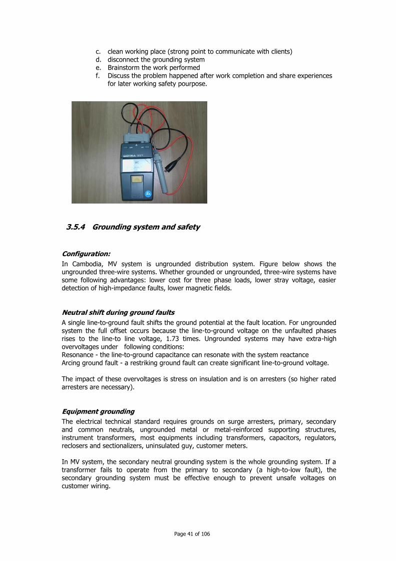
c. clean working place (strong point to communicate with clients)
d. disconnect the grounding system e. Brainstorm the work performed
f. Discuss the problem happened after work completion and share experiences for later working safety pourpose.
3.5.4 Grounding system and safety
Configuration:
In Cambodia, MV system is ungrounded distribution system. Figure below shows the ungrounded three-wire systems. Whether grounded or ungrounded, three-wire systems have
some following advantages: lower cost for three phase loads, lower stray voltage, easier detection of high-impedance faults, lower magnetic fields.
Neutral shift during ground faults
A single line-to-ground fault shifts the ground potential at the fault location. For ungrounded
system the full offset occurs because the line-to-ground voltage on the unfaulted phases rises to the line-to line voltage, 1.73 times. Ungrounded systems may have extra-high
overvoltages under following conditions: Resonance - the line-to-ground capacitance can resonate with the system reactance
Arcing ground fault - a restriking ground fault can create significant line-to-ground voltage.
The impact of these overvoltages is stress on insulation and is on arresters (so higher rated
arresters are necessary).
Equipment grounding
The electrical technical standard requires grounds on surge arresters, primary, secondary
and common neutrals, ungrounded metal or metal-reinforced supporting structures,
instrument transformers, most equipments including transformers, capacitors, regulators, reclosers and sectionalizers, uninsulated guy, customer meters.
In MV system, the secondary neutral grounding system is the whole grounding system. If a
transformer fails to operate from the primary to secondary (a high-to-low fault), the secondary grounding system must be effective enough to prevent unsafe voltages on
customer wiring.

Page 42 of 106
Secondary grounding problems
There are some common problems of secondary grounding: open secondary neutral, neutral and safety ground reversed in the facility, neutral and safety ground connected in the
facility.
Soil resistivity
Soil resistivity is primarily affected by:
Moisture - moisture is one the main factors determining soil resistivity. The dryer the soil
is, the higher resistivity is. Temperature - above the freezing point of water, temperature does not impact resistivity
significantly. Salts - the presence of soluble salts significantly impacts the resistivity.
Corrosion issues:
Corrosion is major consideration for grounding electrodes. Ground rods are normally copper-clad steel or galvanized steel. Most grounded wires are copper. Steel and aluminium corrode
too quickly for grounding use. But copper is attractive to thieve.
Mixing metals significantly increases corrosion. This is galvanic corrosion, because different
metals create an electrochemical battery in the soil. Galvanic corrosion between dissimilar metals can eat up grounding electrodes.
Copper has naturally good properties that limit corrosion. A zinc coating on a steel ground rod (galvanized ground rod) provides corrosion protection for the rod. With lower soil
resistivity, grounding electrodes corrodes faster.
To limit excessive corrosion caused by different metals, avoid using different grounding rods
or provide as much separation as possible between ground electrodes of different metals.
With galvanized steel rods, use steel or aluminium pole ground leads. With copper-clad steel rods, use copper down leads.
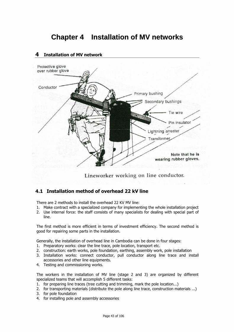
Page 43 of 106
CChhaapptteerr 44 IInnssttaallllaattiioonn ooff MMVV nneettwwoorrkkss
4 Installation of MV network
4.1 Installation method of overhead 22 kV line
There are 2 methods to install the overhead 22 KV MV line:
1. Make contract with a specialized company for implementing the whole installation project 2. Use internal force: the staff consists of many specialists for dealing with special part of
line.
The first method is more efficient in terms of investment efficiency. The second method is
good for repairing some parts in the installation.
Generally, the installation of overhead line in Cambodia can be done in four stages: 1. Preparatory works: clear the line trace, pole location, transport etc.
2. construction: earth works, pole foundation, earthing, assembly work, pole installation
3. Installation works: connect conductor, pull conductor along line trace and install accessories and other line equipments.
4. Testing and commissioning works.
The workers in the installation of MV line (stage 2 and 3) are organized by different specialized teams that will accomplish 5 different tasks:
1. for preparing line traces (tree cutting and trimming, mark the pole location...) 2. for transporting materials (distribute the pole along line trace, construction materials ...)
3. for pole foundation
4. for installing pole and assembly accessories

Page 44 of 106
5. for installing conductors.
Machine and tools used in overhead line installation are as follows:
transport means: truck, crane lorry, for earth works: shovel, drilling car
tools for handling, pulling and lifting: crane, hoist, pulley,
4.2 Construction works
To start construction works when installing overhead line, some preparatory works shall be
done as follows: Trees must be cut out or trimmed if it is possible.
prepare place for materials if it is necessary, install temporary electrical network from for e.g. an independent
generator.
Rearrange other installations on intersection point.
Inspection of materials before sending them to site (e.g. presence of crack on the concrete pole, size and number of accessories, measuring insulator resistance (R >= 3000 Mohms)
4.3 Preparation foundation for pole
a. Earth works:
may be manual works or with drilling truck
or may be by excavator or using explosive material, air hammer (for rock place )
b. Foundation making;
supporting pole
dead end pole when soil is soft (weak stratum)
c. Earthing Dig soil till 0.5m depth or 0.1m for rock type soil
k xk
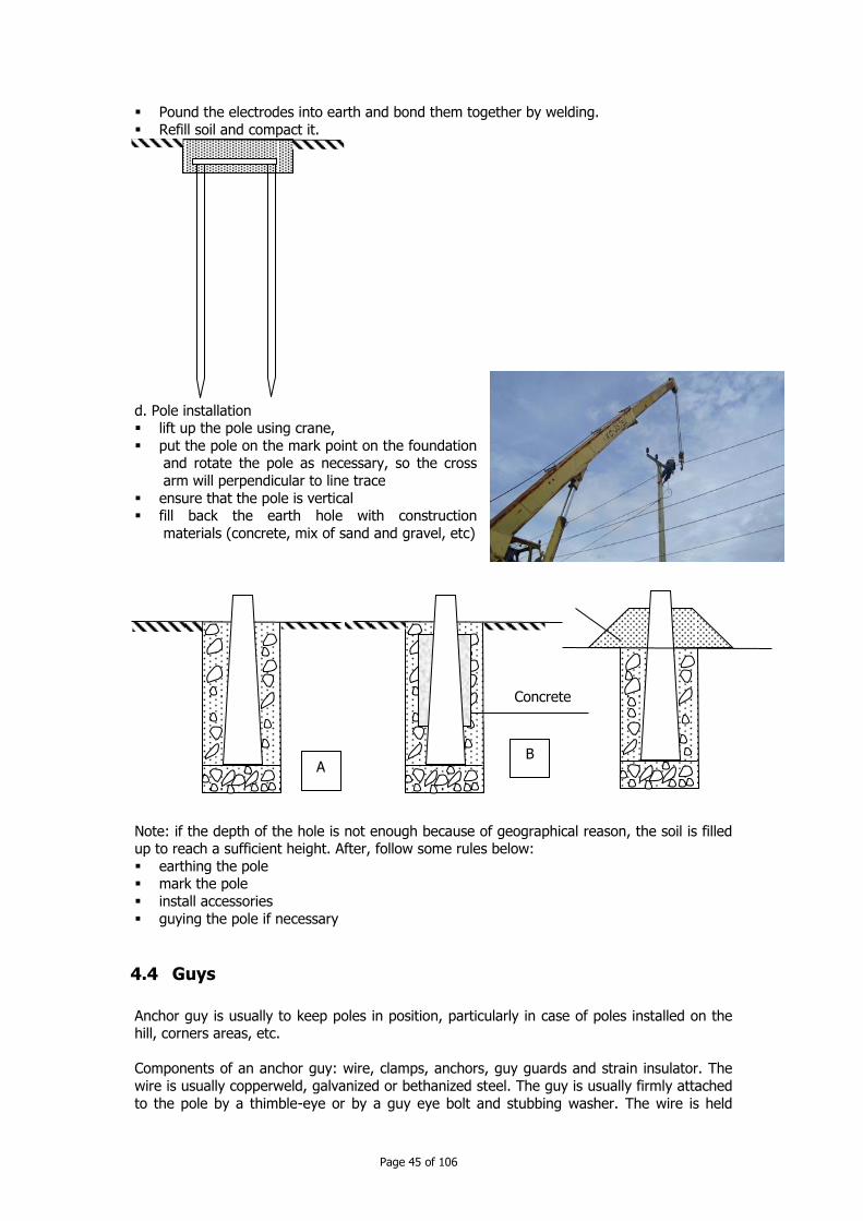
Page 45 of 106
Pound the electrodes into earth and bond them together by welding.
Refill soil and compact it.
d. Pole installation lift up the pole using crane,
put the pole on the mark point on the foundation and rotate the pole as necessary, so the cross
arm will perpendicular to line trace
ensure that the pole is vertical fill back the earth hole with construction
materials (concrete, mix of sand and gravel, etc)
Note: if the depth of the hole is not enough because of geographical reason, the soil is filled up to reach a sufficient height. After, follow some rules below:
earthing the pole mark the pole
install accessories
guying the pole if necessary
4.4 Guys
Anchor guy is usually to keep poles in position, particularly in case of poles installed on the hill, corners areas, etc.
Components of an anchor guy: wire, clamps, anchors, guy guards and strain insulator. The
wire is usually copperweld, galvanized or bethanized steel. The guy is usually firmly attached
to the pole by a thimble-eye or by a guy eye bolt and stubbing washer. The wire is held
A B
Concrete
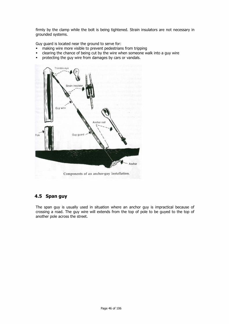
Page 46 of 106
firmly by the clamp while the bolt is being tightened. Strain insulators are not necessary in
grounded systems.
Guy guard is located near the ground to serve for: making wire more visible to prevent pedestrians from tripping
clearing the chance of being cut by the wire when someone walk into a guy wire
protecting the guy wire from damages by cars or vandals.
4.5 Span guy
The span guy is usually used in situation where an anchor guy is impractical because of crossing a road. The guy wire will extends from the top of pole to be guyed to the top of
another pole across the street.

Page 47 of 106
4.6 Stub guy
The stub guy is used to adjust the clearances of cable. It is just a piece of wood to which the guy wire is attached. The stub guy wire must allow enough clearance for traffic.
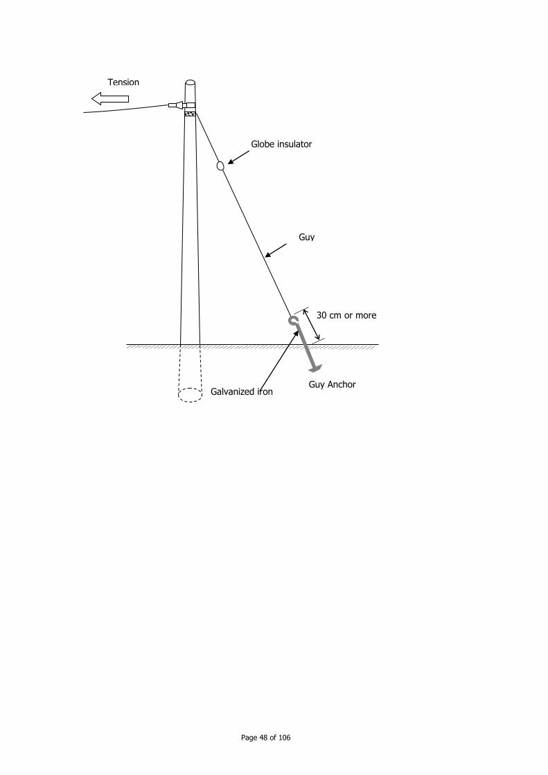
Page 48 of 106
Tension
Guy
Guy Anchor
Globe insulator
Galvanized iron
30 cm or more
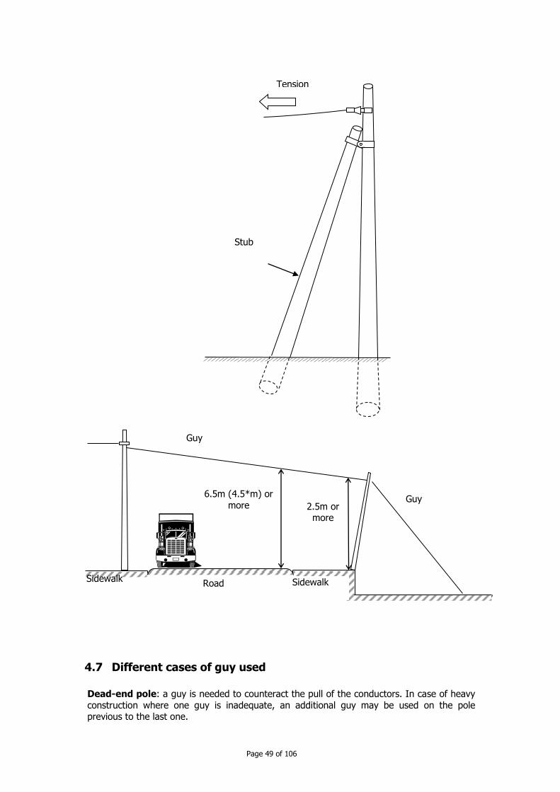
Page 49 of 106
4.7 Different cases of guy used
Dead-end pole: a guy is needed to counteract the pull of the conductors. In case of heavy
construction where one guy is inadequate, an additional guy may be used on the pole previous to the last one.
Tension
Stub
Guy
Sidewalk
6.5m (4.5*m) or
more 2.5m or more
Road Sidewalk
Guy

Page 50 of 106
Corners are treated like dead-ends. Two guys should be used to counterbalance the pull of
one set of wires each.
Conductors form an angle: the pole is submitted to an additional stress. Side guys are
attached to the pole to balance the side pull forces.
Branch line shoots from the pole: the weight of branch causes a side pull. The side pull is
counterbalanced by side guys
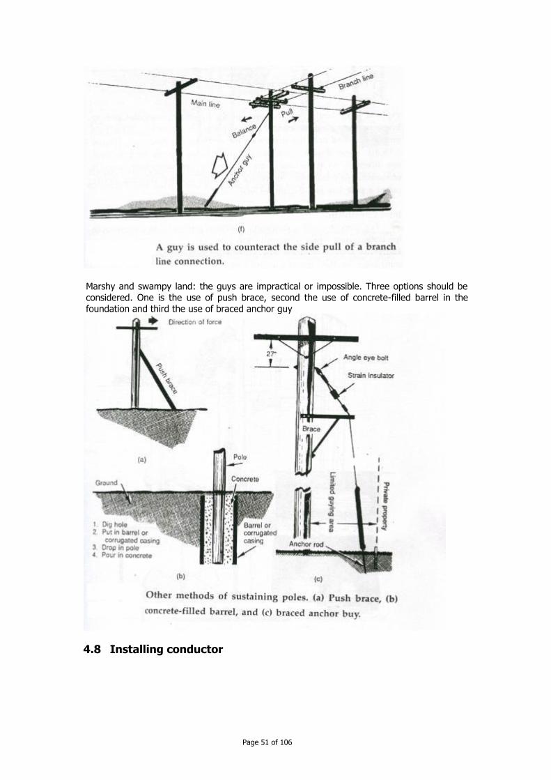
Page 51 of 106
Marshy and swampy land: the guys are impractical or impossible. Three options should be
considered. One is the use of push brace, second the use of concrete-filled barrel in the
foundation and third the use of braced anchor guy
4.8 Installing conductor

Page 52 of 106
4.8.1 Clearance
Along the road, street
5,5 m
6.5m
Cross the road or street

Page 53 of 106
Where there are not roads or streets
4 m
Road
lateral proximity
height
Direct
proximity
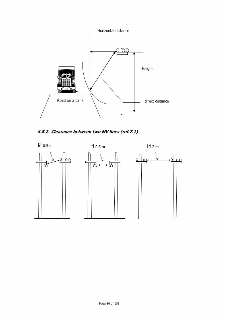
Page 54 of 106
4.8.2 Clearance between two MV lines (ref.7.1)
Road on a bank direct distance
Height
Horizontal distance
0.5 m 0.5 m 2 m

Page 55 of 106
4.9 Connection of conductors
Conductors shall be connected firmly and the resistance of conductors shall not increase. If it is necessary, the connected conductor shall undergo a resistance test.
4.9.1 At insulator level
Usually, the conductor is spliced by overlapping the ends and twisting the ends together,
taking three or four turns.
0.5 m 1 m 2 m
Insulated conductor
Bare conductor
R1 (Ohm)
R1 R2
R2(Ohm)
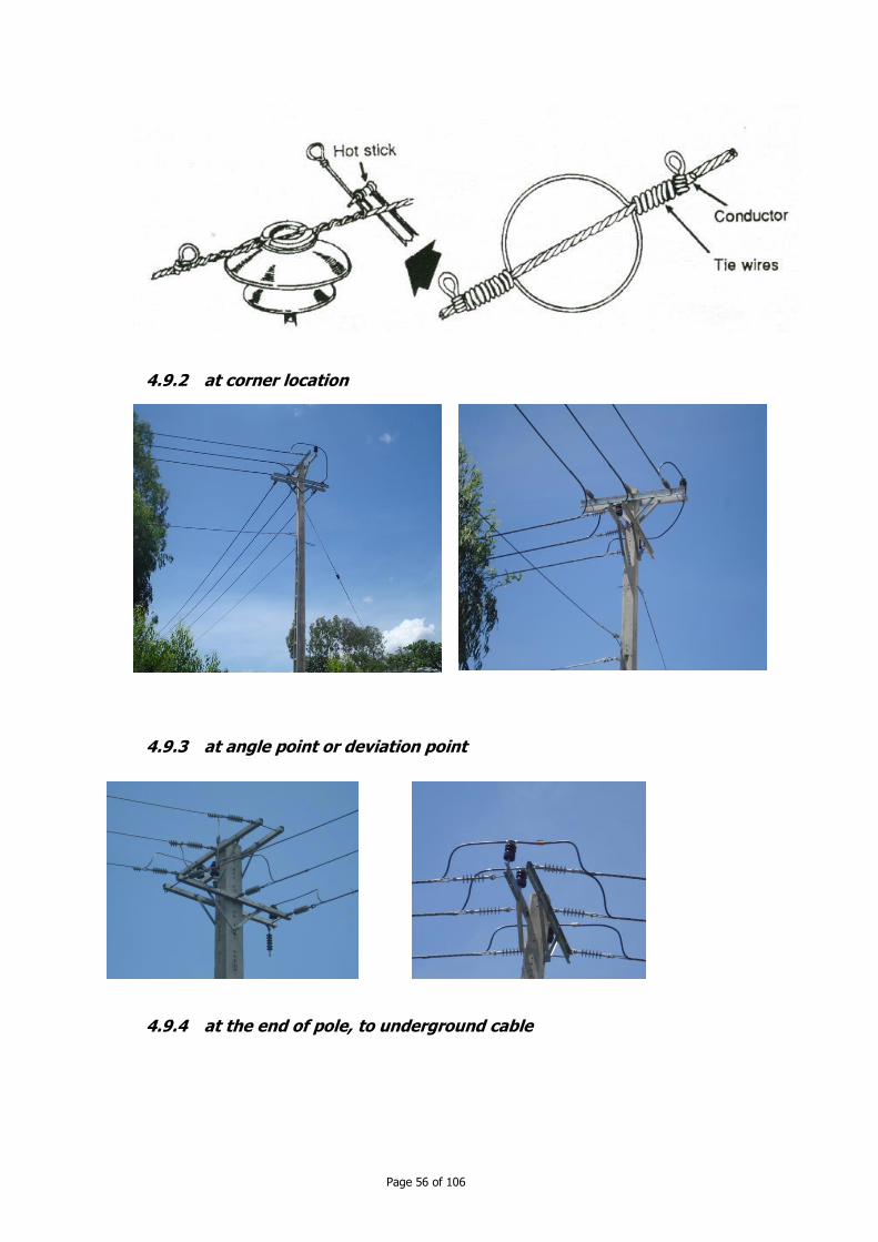
Page 56 of 106
4.9.2 at corner location
4.9.3 at angle point or deviation point
4.9.4 at the end of pole, to underground cable
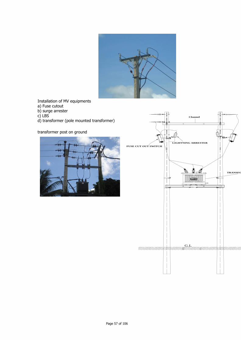
Page 57 of 106
Channel
G.L
FUSE CUT OUT SWITCH
LIGHTNING ARRESTER
TRANSFORMER
Installation of MV equipments
a) Fuse cutout b) surge arrester
c) LBS d) transformer (pole mounted transformer)
transformer post on ground
Page 58 of 106
CChhaapptteerr 55:: OOppeerraattiioonn,, mmaaiinntteennaannccee aanndd ttrroouubbllee
sshhoooottiinngg ooff MMVV nneettwwoorrkkss
5 Installation and inspection
Operation of MV networks consists of supply via MV network electricity load to comply with Standard of Performance of Electricity Service in Cambodia (issued by EAC). Operator shall
ensure the quality of electricity, the reliable and sustained service, efficiency of MV network.
5.1 Tasks in MV network operation
switch on/off a transformer post switch on/off a MV load
Do voltage regulation optimization of MV network (loss of power, loss of energy)
Reliability improvement.
Increase the capacity of MV network. (not consider here) liquidation of fault cause or prevent eventual fault
5.2 Organisation of the MV operation unit
Staff working on LV line cannot work with MV line without special training (safety training) At least 2 people qualified for working on 22 kV line in the MV line unit.
5.3 Operation and maintenance works
5.3.1 Switch off a MV load
No LBS
Switch off the LV load (so after some MV interrupters, a LV circuit breaker should be
used on LV side) Switch off the transformer if any.
Switch off the MV line.
5.3.2 Maintenance and inspection
The best maintenance for MV distribution network is trimming tree (largest expense for the
utility) Beyond tree trimming, the maintenance practice varies widely. Most of distribution
equipments are maintenance fee: transformer, capacitors, insulators, wires, cables. Oil filled switches, reclosers and regulators need only occasional maintenance.

Page 59 of 106
Process in maintenance:
Identify old and failing equipment and targeting it for replacement. Equipment deteriorates over time. Several rural enterprises have increasingly older infrastructures.
Equipment fails at varying rates over its lifetime. Do restoration (e.g. when storms knock lines and equipment down, and crews put them
back.
Do tracking equipment quality and failures (to help improve the reliability of MV network). For overhead MV line, most failure causes are external but still tracking
equipment failure and targeting bad equipment help the operator to maintain the service. It should be noted that failure occurs in clusters: particular manufacturer,
particular models, and particular manufacturing years. Identify non proper application of equipment to prevent overloading equipment
excessively and to apply good surge protection.
Elaborate inspection program.
Inspection techniques used for distribution line:
Visual inspections (drive-by): find severely degraded poles, broken conductor strands,
and broken insulators. infrared thermography
wood pole test: e.g. hammer test
operation counts (recloser, regulator tap changer) oil test.
Inspection (and monitoring) method:
Inspection and monitoring is a method to find out where a fault could be possible, so REE can prevent this fault.
The measures are as follows: periodical inspection of overhead line (one time in six month by a technician and one
time in a year by an electrical engineer) inspection by an inspector one time in 6 year or by necessity
inspection when there are incidents or failure: fire case near or along MV line, strong
wind or storm, after fault outage, after successful operation of recloser. measure insulation resistance: on time in 6 years
measure the earth resistance: one time in 10 years to verify clearance.
5.3.3 Repair method
Pole:
when pole is declined from vertical line
when there is crack (concrete pole). Small cracking shall be covered by painting. Serious cracking can lead to pole replacement.
Line:
Line repair include replacement of conductor, connector, surge arrestor, insulator etc.
Page 60 of 106
When do replacement, the materials shall be equivalent or superior to old materials. The
conductors should have same brand name, type, size and the strand direction. Put new conductor ready before take out old conductor.
Remark: The repair shall be conducted while the circuit is switched off and by following safety procedure. The replacement of insulator without switching off the circuit requires very
high safety and security measures to be taken into account.
About the safety rule, please refer to chapter 3.
5.4 Safety of Third Persons
1. Safety of Third Persons at Power Stations, Substations and Switching Stations.
a. External fences or walls to separate outside from compound. The height of external fences
or walls shall not be lower than 1800 mm. Boundary Clearance from these fences or walls to electrical equipment shall not be less than the values described in the following table:
Nominal voltage Height of wall or fence Boundary clearances [mm] 22 kV not less than 1<8m not less 2.1 m from wall
not less 2.6 m from fence b. Signs to alert third persons to danger shall be installed at the entrances/exits. Moreover,
where necessary, signs shall also be displayed on walls and fences.
c. Locking devices or other appropriate devices shall be installed at the entrances/exits.
2. Safety of Third Persons at Electric Supporting Structures.
Appropriate measures shall be taken to prevent third persons from climbing supporting structures of overhead electrical lines. To prevent danger to third persons related the
supporting structures of electrical lines the following measures shall be taken into account: any metal steps on supporting structures shall be installed more than 1.8m from the
ground. warning signs to alert the third persons to danger shall be installed at each supporting
structure.
5.5 Environmental Protection
Compliance with Environmental Standards
To prevent environmental pollution, the electric power facilities shall be constructed in
accordance with the environmental laws and regulations of the Kingdom of Cambodia.
Prohibition of Installation of Electrical Machines or Equipment containing Polychlorinated Biphenyls (PCBs):
The installation of new electrical equipment using insulating oil that contains greater than 0.005 percent (50 ppm) polychlorinated biphenyls (PCBs) shall be prohibited.
Page 61 of 106
CChhaapptteerr 66 :: RRoolleess aanndd rreessppoonnssiibbiilliittiieess
6 Roles and responsibilities
The electricity law of Cambodia lay out the legal framework of power sector development.
Three important players in this framework are MIME, EAC and EdC. MIME is responsible in the policy and planning e development. So MIME will not plan the MV
line in the distribution area. EdC is a big operator and has right to transport electricity in the Kingdom of Cambodia and has responsibility in planning all subtransmission lines in order to
transport electricity (bought by EdC from IPP) to rural area (to sell to EAC licensees). EAC
will coordinate the action of rural licensees in building MV line, so there will not conflict of interest between licensees and EdC.
This framework involves many stakeholders of Electricity Supply dealing with Medium
Voltage lines: household
MV consumer Operator, EAC licensee
Technicians
Electricity Authority of Cambodia Ministry of Industry, Mines and Energy
local authority (commune authority, district authority) Electricité du Cambodge
Ministry of Public Works and Transport
Households are the users of electricity. To supply electricity to user, the electricity is
transported from source via transmission line, MV distribution network, transformer post and LV line. The household is therefore related to all electrical installation. The household should
be aware about clearance of the MV line to the object in his property like gate, tree, house etc. The problem for the investor is cutting tree that some household require compensation.
So household should know the regulation about object in their property and the part of
public land for developing infrastructure such as road, electrical network, water supply etc. Household must know that in some necessary case the MV line shall cross their property,
and in this case household can require compensation.
MV consumers are for example big hotel, rice mild, enterprise etc. MV consumers sign
power purchase agreement with operator. If there is not MV line nearby the MV consumer location, MV consumer must build MV line from his facilities to operator MV line. Depending
on agreement, MV consumer shall responsible on their transformer post, keep overall power factor not less than some value (e.g. 0.85) and maintain their facilities, so there are not
troubleshooting to MV line.
The operator is a licensee, holding distribution license or special purpose transmission
license. The operator shall respect the terms and conditions of his license issued by EAC. To obtain this license, the enterprise or company apply for Prakas from MIME to have right to
invest in power sector. If enterprise receives right to build sub-transmission 22 kV line, it can start building the main MV line. If enterprise receives right to distribute electricity in some
area, he will build the MV network by technical necessity and by economic reason.
The operator is responsible in ensuring normal operation of his MV network or sub-transmission line with respect to EdC's grid code. He cannot sell the infrastructure to anyone.
In general MV line may be connected to EdC system via MV line or MV feeder in grid
substation.

Page 62 of 106
The operator has responsibility to improve the reliability and increase the capacity of the MV
network and expand the network to comply with the load demand.
MIME shall be responsible for setting and administrating the government policies, strategies and planning in power sector. So MIME has right to issue Prakas to investor of MV line
following the planning scheme. But because MIME elaborates strategic development plan in power sector, MIME do not plan on developing MV network.
To ensure the quality and safety of infrastructure in power sector, MIME issues electric
technical standard.
DIME (provincial department of industry, mines and energy) DIME play role like MIME but limited to a capacity of 125 kVA of generation and not big area
of distribution zone.
Local authority
Coordinate and solve some conflicts of interest arisen between operator and local people in construction phase. Coordinate tree trimming and cutting during construction and
maintenance.
EAC (Electricity Authority of Cambodia)
EAC is responsible in coordinating planning work of EdC with the expansion plan of licensee, approving the planning of REE. After construction EAC will inspect the MV infrastructure
before the operation. EAC could also assist rural operators in designing the MV network, if they ask for assistance. It should remark that when REE will connect to EdC grid, EdC will
test the infrastructure one more.

Page 63 of 106
CChhaapptteerr 77:: BBaassiicc EElleeccttrriicciittyy FFuunnddaammeennttaallss
7 Component of a distribution system
The society must use energy resources in the form such as water, wind, oil, coal etc. to
accomplish tasks the societies consider desirable: heating, cooling, lighting etc. To be useful
energy must be available at the place where the work is to be done. The electricity via distribution system allows the raw energy resources and the equipments (appliances) to be
separated by great distances. Thus electricity must be generated at the power plant and transported to consumer by distribution network at the same time when the societies need.
7.1 System components
Generation: the production of electricity
Transmission: the system of lines that transport the electricity from the generating plants
to the area in which it will be used. (in our rural system, this refers to sub-transmission 22 kV line). For a stand alone system, there are not transmission lines.
Distribution: the system of lines that connect the individual customers to the electric power supply system.
The generation has to be located away from heavily populated area when it is possible
because land is less expensive and the plants may be closer to the source of fuel they use.
Electricity is then transported to the area of use by the transmission lines and distributed to the customers at lower voltages by the distribution lines.
7.1.1 Voltage levels
The transport of electricity is accompanied by losses in conductors. The major losses are
proportional to the current squared. As power is the product of current time voltage, thus when the voltage is increased, the current is decreased, so the loss can be reduced
dramatically. The electric power technical standard of the Kingdom of Cambodia sets the
voltage levels for the distribution line. For the generation there is no setting of voltage level. In our rural distribution system, there are two voltage levels:0.4 kV and 22 kV.
7.1.2 Frequency
Many different frequencies are used in power systems. But now there are only two frequencies 50Hz and 60 Hz. In Cambodia the rated frequency is 50Hz.
7.1.3 Transmission
The source of losses in transmission system is the same as for transmission and distribution lines.
Resistance: the series resistance of a conductor depends on the resistivity of the conductor material, its length, temperature and the skin effect.
DC resistance R is directly proportional to the resistivity rho and length (l) and inversely proportional to the cross section (s):

Page 64 of 106
R = x l / s
Stranded conductors are spiralled. Spiralling typically adds about 2% to the length. Resistance increases almost linearly with temperature.
Skin effect refers to the fact that as frequency increases current flow shifts toward the
surface of a conductor. The skin effect can result in the ac resistance of a large conductor
being about 20% higher than the dc resistance. Reactance: The magnetic flux produced by the ac current produces series inductive
reactance (XL). The reactance does not dissipate active power but results in voltage drop along the line and reactive power (volt-ampere-reactive). Generator should supply
reactive power on the line in addition to the load power.
Capacitance: Conductors separated by a distance have capacitance. The capacitance of the lines must be charged before a line can transfer power. Some power is shunted to
ground from the line through the capacitive reactance. Corona: Corona is caused by the breakdown of the air around a transmission line
because of high voltage. The effect is most severe around small conductors and at sharp points and corners. Corona absorbs energy from the line.
7.1.4 Distribution
A distribution network is subject to all the losses that a transmission system has. Because of lower voltages bundling of conductors to prevent corona is not necessary.
Simplified line impedance calculations
The impedance of overhead line is:
Z1 = R0 + jk1*log10(GMDph/GMRph)
Where Ro = resistance of the phase conductor in ohm/distance
k1 = 0.0529f/60 if output in ohm/1000ft f = frequency in hertz
GMRph = geometric means radius of the phase conductor in mm
GMDph = geometric means distance between the phase conductors in m.
The zero-sequence impedance (3 wire overhead line) Z0 = Rph + 3Rearth + j3k1*log10 (Dearth/sqrt3(GMRph*GMDph²)
Where Rearth = resitance of the earth return path Dearth =equivalent depth of the earth return current in ft = 2160 sqrt(rho/f)
rho = earth resistivity in ohm/m
Major effects:
Conductor size affects resistance: the larger the conductor is, the lower the resistance. The change in reactance is small.
Conductor spacing: Increasing spacing increases Z1 but decreases Zo. The effects are modest.
Earth resistivity: the earth resistivity does not change the earth return resistance because
it depends only on frequency. Higher resistivities are raising the reactance. Grounding: Z1 stay the same.
Z2 = Z1
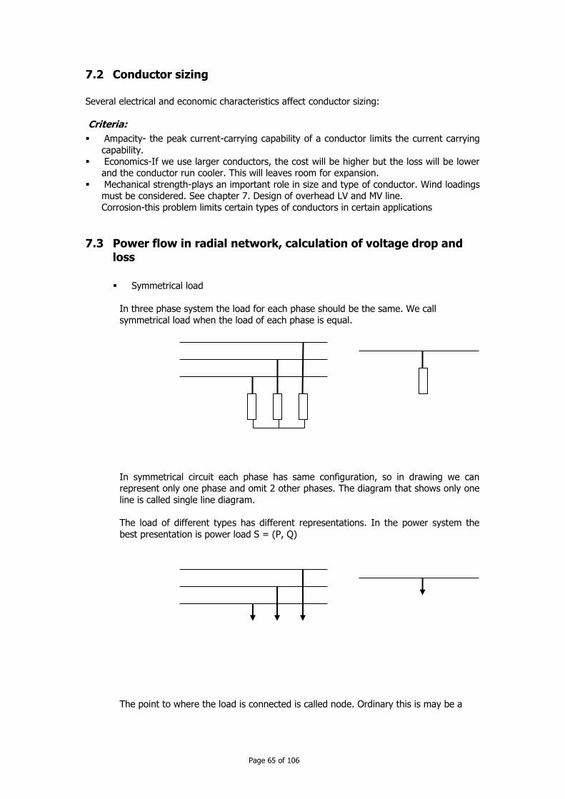
Page 65 of 106
7.2 Conductor sizing
Several electrical and economic characteristics affect conductor sizing:
Criteria:
Ampacity- the peak current-carrying capability of a conductor limits the current carrying
capability.
Economics-If we use larger conductors, the cost will be higher but the loss will be lower and the conductor run cooler. This will leaves room for expansion.
Mechanical strength-plays an important role in size and type of conductor. Wind loadings must be considered. See chapter 7. Design of overhead LV and MV line.
Corrosion-this problem limits certain types of conductors in certain applications
7.3 Power flow in radial network, calculation of voltage drop and loss
Symmetrical load
In three phase system the load for each phase should be the same. We call symmetrical load when the load of each phase is equal.
In symmetrical circuit each phase has same configuration, so in drawing we can represent only one phase and omit 2 other phases. The diagram that shows only one
line is called single line diagram.
The load of different types has different representations. In the power system the
best presentation is power load S = (P, Q)
The point to where the load is connected is called node. Ordinary this is may be a
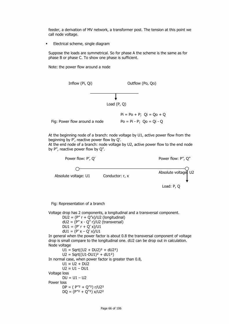
Page 66 of 106
feeder, a derivation of MV network, a transformer post. The tension at this point we
call node voltage.
Electrical scheme, single diagram
Suppose the loads are symmetrical. So for phase A the scheme is the same as for
phase B or phase C. To show one phase is sufficient.
Note: the power flow around a node
At the beginning node of a branch: node voltage by U1, active power flow from the beginning by P’, reactive power flow by Q’.
At the end node of a branch: node voltage by U2, active power flow to the end node
by P”, reactive power flow by Q”.
Voltage drop has 2 components, a longitudinal and a transversal component.
DU2 = (P” r + Q”x)/U2 (longitudinal) dU2 = (P” x - Q” r)/U2 (transversal)
DU1 = (P’ r + Q’ x)/U1
dU1 = (P’ x – Q’ x)/U1 In general when the power factor is about 0.8 the transversal component of voltage
drop is small compare to the longitudinal one. dU2 can be drop out in calculation. Node voltage
U1 = Sqrt((U2 + DU2)² + dU2²) U2 = Sqrt((U1-DU1)² + dU1²)
In normal case, when power factor is greater than 0.8,
U1 ≈ U2 + DU2 U2 ≈ U1 – DU1
Voltage loss DU = U1 – U2
Power loss
DP = ( P”² + Q”²) r/U2² DQ = (P”² + Q”²) x/U2²
Fig: Power flow around a node
Load (P, Q)
Outflow (Po, Qo) Inflow (Pi, Qi)
Pi = Po + P; Qi = Qo + Q
Po = Pi - P; Qo = Qi - Q
Fig: Representation of a branch
Conductor: r, x
Load: P, Q
Absolute voltage: U1 Absolute voltage: U2
Power flow: P’, Q’ Power flow: P”, Q”

Page 67 of 106
DP = ( P’² + Q’²) r/U1² DQ = (P’² + Q’²) x/U1²
Radial network is a network whose configuration does not contain any loop (tree like
configuration)
Example:
Beginning Ending Branch
A B AB B C BC
C D CD
D E DE E is last node B F BF F is last node
D G DG G H GH H is last node
To find out the path from the first node to last node
1- Write down branch of last node, ex: DE 2- Get the previous node to the node D: C so we have CDE
3- Repeat this process until the first node BCDE
ABCDE
For the last node F: ABF For the last node H: ABCDGH
Compute a radial network (approximately) 1. Find the path to each last node
2. Compute the power flow for each branch 3. From the first to the last node compute all node voltage, voltage drop in each
branch and power loss.
Fig: Radial network
A B C D E
F
G
H
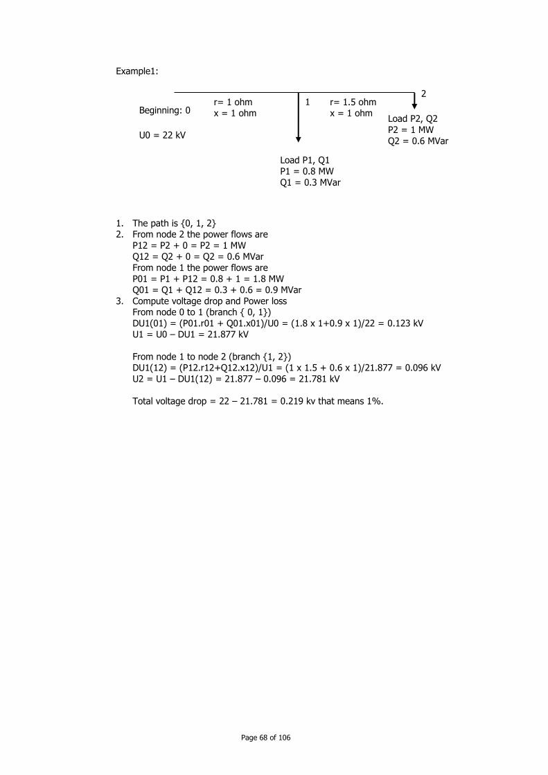
Page 68 of 106
Example1:
1. The path is {0, 1, 2} 2. From node 2 the power flows are
P12 = P2 + 0 = P2 = 1 MW Q12 = Q2 + 0 = Q2 = 0.6 MVar
From node 1 the power flows are
P01 = P1 + P12 = 0.8 + 1 = 1.8 MW Q01 = Q1 + Q12 = 0.3 + 0.6 = 0.9 MVar
3. Compute voltage drop and Power loss From node 0 to 1 (branch { 0, 1})
DU1(01) = (P01.r01 + Q01.x01)/U0 = (1.8 x 1+0.9 x 1)/22 = 0.123 kV U1 = U0 – DU1 = 21.877 kV
From node 1 to node 2 (branch {1, 2}) DU1(12) = (P12.r12+Q12.x12)/U1 = (1 x 1.5 + 0.6 x 1)/21.877 = 0.096 kV
U2 = U1 – DU1(12) = 21.877 – 0.096 = 21.781 kV
Total voltage drop = 22 – 21.781 = 0.219 kv that means 1%.
Beginning: 0 Load P2, Q2
P2 = 1 MW
Q2 = 0.6 MVar
Load P1, Q1
P1 = 0.8 MW
Q1 = 0.3 MVar
1 2
U0 = 22 kV
r= 1 ohm x = 1 ohm
r= 1.5 ohm x = 1 ohm
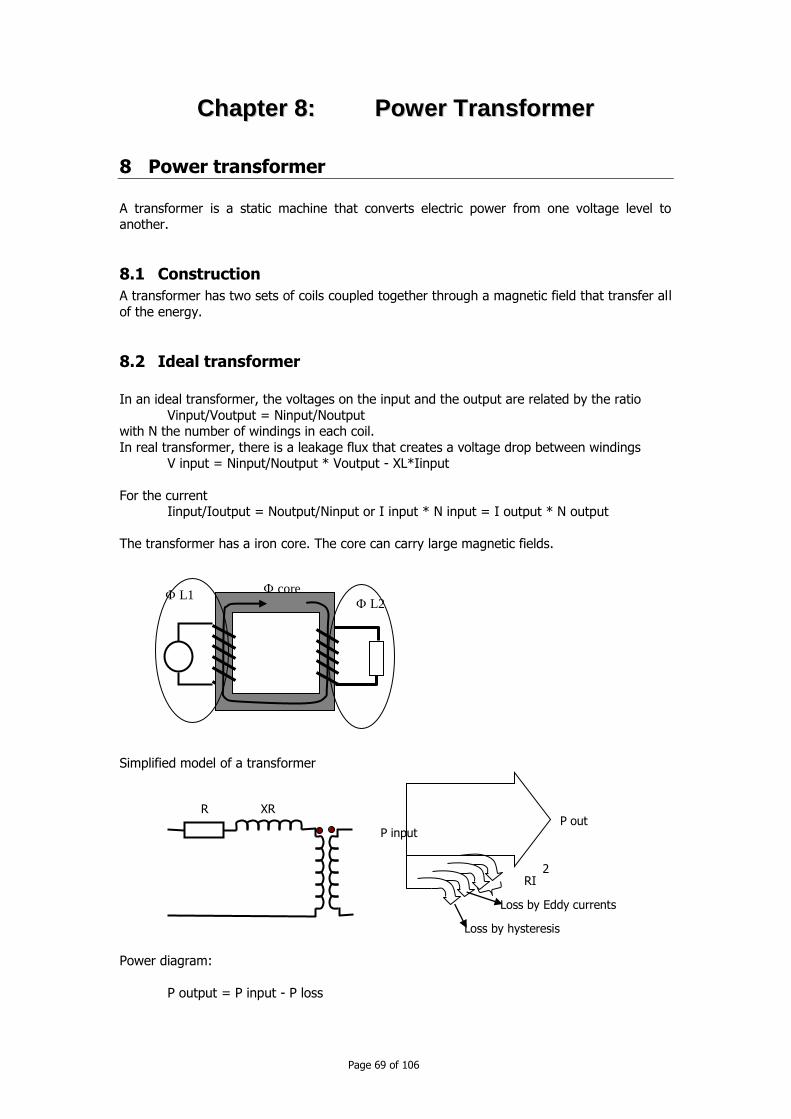
Page 69 of 106
CChhaapptteerr 88:: PPoowweerr TTrraannssffoorrmmeerr
8 Power transformer
A transformer is a static machine that converts electric power from one voltage level to another.
8.1 Construction
A transformer has two sets of coils coupled together through a magnetic field that transfer all
of the energy.
8.2 Ideal transformer
In an ideal transformer, the voltages on the input and the output are related by the ratio
Vinput/Voutput = Ninput/Noutput with N the number of windings in each coil.
In real transformer, there is a leakage flux that creates a voltage drop between windings V input = Ninput/Noutput * Voutput - XL*Iinput
For the current Iinput/Ioutput = Noutput/Ninput or I input * N input = I output * N output
The transformer has a iron core. The core can carry large magnetic fields.
Simplified model of a transformer
Power diagram:
P output = P input - P loss
core
L2 L1
R XR
RI 2
Loss by Eddy currents
Loss by hysteresis
P out P input

Page 70 of 106
The loss can result from (1) Power loss in the core by hysteresis and by Eddy
currents and (2) by the thermal loss in the windings.
In the simplified model serial impedance is sufficient for calculation including local flows, short-circuit calculation, motor starting or unbalance.
The leakage reactance causes voltage drop on a loaded transformer. Leakage impedance is
under control of the designer, so the maker will make transformer with customized impedances. For example, transformer with great capacity has high leakage impedance in
order to control the fault current.
8.3 Insulation materials
The mineral oil filled many distribution transformers. The oil has two functions: insulation and
conducting heat. Oil is flammable (flash point at 150 degree C). Oil has high dielectric
strength (86.6 kV/cm). Oil also protects coils, core and other materials from corrosion.
8.4 Distribution transformer
8.4.1 Single phase transformer
Single phase transformer supplies single phase service. We can use 2 or 3 single phase units
in a variety of configuration to supply 3 phase service.
Load current I = S(kVA)/V(kV) Where S(kVA) = transformer kVA rating
V (kV) = line to ground voltage rating in kV.
Impedance:
R = W cu/ (10*S(kVA)) Where W cu = W tot - Wnl = loss at rated load, W
W tot = total losses estimated at rated load, W
W nl = no-load losses W
X = sqrt(Z²-R²) Where
Z = name plate impedance magnitude %
8.4.2 Three phase transformer
Construction:
There are five-legged wound core, four legged stacked core, three legged stacked core.

Page 71 of 106
Connection scheme of windings:
Different ways of windings connection are delta, floating-wye or grounded wye. The windings may be grounded or ungrounded.
Primary winding may be wye-connection or delta connection. On the secondary side the delta
configuration and the grounded wye configuration are used.
Grounded wye secondary: We have
grounded wye - grounded wye
delta - grounded wye
five legged wound core
four legged stacked core
three legged stacked core
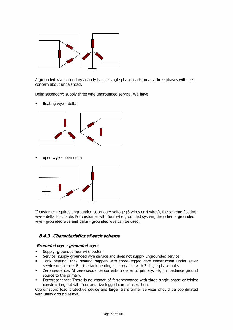
Page 72 of 106
A grounded wye secondary adaptly handle single phase loads on any three phases with less
concern about unbalanced.
Delta secondary: supply three wire ungrounded service. We have
floating wye - delta
open wye - open delta
If customer requires ungrounded secondary voltage (3 wires or 4 wires), the scheme floating wye - delta is suitable. For customer with four wire grounded system, the scheme grounded
wye - grounded wye and delta - grounded wye can be used.
8.4.3 Characteristics of each scheme
Grounded wye - grounded wye:
Supply: grounded four wire system
Service: supply grounded wye service and does not supply ungrounded service Tank heating: tank heating happen with three-legged core construction under sever
service unbalance. But the tank heating is impossible with 3 single-phase units. Zero sequence: All zero sequence currents transfer to primary. High impedance ground
source to the primary.
Ferroresonance: There is no chance of ferroresonance with three single-phase or triplex construction, but with four and five-legged core construction.
Coordination: load protective device and larger transformer services should be coordinated with utility ground relays.

Page 73 of 106
Delta-Grounded Wye connection:
Delta windings establish a local grounding reference and blocks zero sequence currents from entering the primary.
Supply: 3-wire or 4-wire system Service: supplies grounded wye service, does not supply ungrounded service
Ground faulted: blocks zero sequence, upstream are isolated from line to ground fault at
secondary Harmonics: Zero-sequence harmonics and third harmonics cannot get through to the
primary. No primary ground source: delta - grounded wye cannot act as a grounding source.
Secondary ground source: independent of the primary-side grounding configuration No tank heating: Delta connection ensures that there are no zero-sequence flux. Three-
legged core transformer can be used.
Ferroresonance: highly susceptible.
Floating-Wye - Delta
Supply: 3-wire or 4-wire system
Service: can supply ungrounded service and four-wire service
Unit failure: can continue to operate if one unit fails if it is rewired as an open wye - open delta.
Voltage unbalance: secondary-side unbalances are mor likely than with a wye secondary connection.
Ferroresonance: Highly susceptible.
Note: If one phase is switched off, the delta on the secondary is broken and the primary
neuter can shift wildly: possible overload by load unbalance. This scheme is best used for supplying three phase load with a smaller amount of single-phase load.
Delta-Delta:
Supply: 3-wire or 4-wire system Service: Can supply ungrounded service and cannot supply grounded wye four-wire
service.
Ferroresonance: Highly susceptible Unit failure: Can continue to operate if one unit fails (as an open delta-open delta)
Circulating current: high circulating current
Open wye-open delta:
Supply: 2 phase and the neutral of a 4-wire grounded system
Service: Can supply ungrounded service, and cannot supply grounded wye four-wire service
Ferro resonance: no
Voltage unbalance: may have high secondary voltage unbalance Primary ground current: high primary-side current unbalance. High currents are forced
into the primary neutral even with balanced loadings.
8.4.4 Neutral stability
Floating wye winding can have an unstable neutral. Unbalanced single-phase loads on the secondary, unequal magnetizing currents, and suppression of third harmonics can shift the
neutral.
Unbalanced loads: Zero sequence currents have no path to flow. Loading one phase drops the voltage on that phases and raises the voltage on the other two phases.
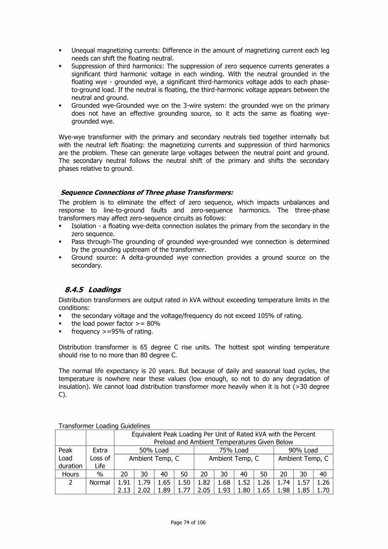
Page 74 of 106
Unequal magnetizing currents: Difference in the amount of magnetizing current each leg
needs can shift the floating neutral. Suppression of third harmonics: The suppression of zero sequence currents generates a
significant third harmonic voltage in each winding. With the neutral grounded in the floating wye - grounded wye, a significant third-harmonics voltage adds to each phase-
to-ground load. If the neutral is floating, the third-harmonic voltage appears between the
neutral and ground. Grounded wye-Grounded wye on the 3-wire system: the grounded wye on the primary
does not have an effective grounding source, so it acts the same as floating wye-grounded wye.
Wye-wye transformer with the primary and secondary neutrals tied together internally but
with the neutral left floating: the magnetizing currents and suppression of third harmonics
are the problem. These can generate large voltages between the neutral point and ground. The secondary neutral follows the neutral shift of the primary and shifts the secondary
phases relative to ground.
Sequence Connections of Three phase Transformers:
The problem is to eliminate the effect of zero sequence, which impacts unbalances and
response to line-to-ground faults and zero-sequence harmonics. The three-phase
transformers may affect zero-sequence circuits as follows: Isolation - a floating wye-delta connection isolates the primary from the secondary in the
zero sequence. Pass through-The grounding of grounded wye-grounded wye connection is determined
by the grounding upstream of the transformer. Ground source: A delta-grounded wye connection provides a ground source on the
secondary.
8.4.5 Loadings
Distribution transformers are output rated in kVA without exceeding temperature limits in the conditions:
the secondary voltage and the voltage/frequency do not exceed 105% of rating. the load power factor >= 80%
frequency >=95% of rating.
Distribution transformer is 65 degree C rise units. The hottest spot winding temperature
should rise to no more than 80 degree C.
The normal life expectancy is 20 years. But because of daily and seasonal load cycles, the
temperature is nowhere near these values (low enough, so not to do any degradation of insulation). We cannot load distribution transformer more heavily when it is hot (>30 degree
C).
Transformer Loading Guidelines
Equivalent Peak Loading Per Unit of Rated kVA with the Percent Preload and Ambient Temperatures Given Below
Peak
Load duration
Extra
Loss of Life
50% Load 75% Load 90% Load
Ambient Temp, C Ambient Temp, C Ambient Temp, C
Hours % 20 30 40 50 20 30 40 50 20 30 40
2
Normal 1.91 2.13
1.79 2.02
1.65 1.89
1.50 1.77
1.82 2.05
1.68 1.93
1.52 1.80
1.26 1.65
1.74 1.98
1.57 1.85
1.26 1.70

Page 75 of 106
4
2.22
2.44 1.61
1.80
1.87 2.06
2.10
2.34 2.50
1.70
1.77 1.97
1.99
2.23 1.38
1.60
1.67 -
1.87
- 1.25
1.48
- -
2.14
2.37 1.56
1.76
1.83 2.02
2.02
2.26 1.44
1.65
1.72 1.93
1.90
2.15 1.30
1.54
1.62 -
1.75
- 1.09
1.40
150 -
2.07
2.31 1.50
1.71
1.79 1.99
1.95
2.20 1.36
1.60
1.68 1.89
1.81
2.08 1.13
1.47
1.56 -
Source ANSI/IEEE C57.91-1981
8.4.6 Power Losses
Load losses, no-load losses, and purchase price are all interrelated. Approaches to reduce
load losses tend to increase no-load losses and vice versa. The average load on most transformers is relatively low (25 to 30% of transformer rating), so the importance of no-load
losses. The total equivalent losses on a transformer are:
Ltotal = P²*FlossLload + Lno-load
Where
Ltotal = average losses, kW (to multiply with 8760 hours/year) P = peak transformer load, per unit
Floss= loss factor, per unit
Lno-load = rated no-load losses, kW Lload = rated load losses, kW
8.5 Paralleling
When replacing a transformer, paralleling transformer during the changeover eliminates the
customer interruption. Criteria for parallel connection of transformers: phasing-the high and low voltage must have the same phasing relationship.
polarity- If the units have different polarity, they should wire accordingly
voltage-the phase to phase and phase to ground voltages on the outputs should be equal.
Before connection, the technician must ensure that the secondary voltages are all zero or
very close to zero. The share of power in each transformer depends on the percent impedance.
8.6 Inrush
Inrush current is the current of magnetizing transformer core when transformer is first energized. The inrush current may approach short-circuit levels. Inrush may cause fuses,
reclosers, or relays to falsely operate. Factors which have impact on inrush current.
Closing point: the point where the circuit closes back in determines how close the core flux can get to maximum. The worst case is when the flux is near its peak.
Design flux-Transformer that is to operate lower on the saturation curve draws less inrush.
Transformer size: Larger transformers draw more inrush. Source impedance: Higher source impedance relative to the transformer size limits the
current that the transformer can pull from the system.
ipeak = io/(1+io*X) Where
io = peak inrush without source impedance in per unit of the transformer rated current.
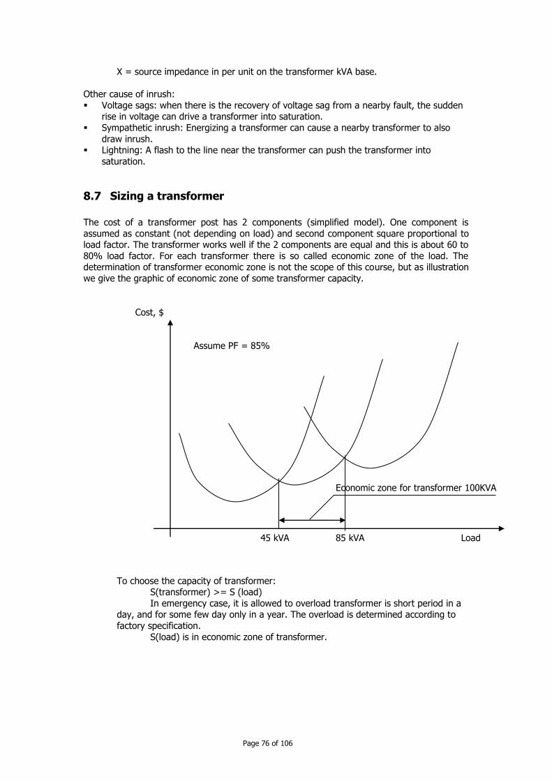
Page 76 of 106
X = source impedance in per unit on the transformer kVA base.
Other cause of inrush:
Voltage sags: when there is the recovery of voltage sag from a nearby fault, the sudden rise in voltage can drive a transformer into saturation.
Sympathetic inrush: Energizing a transformer can cause a nearby transformer to also
draw inrush. Lightning: A flash to the line near the transformer can push the transformer into
saturation.
8.7 Sizing a transformer
The cost of a transformer post has 2 components (simplified model). One component is
assumed as constant (not depending on load) and second component square proportional to load factor. The transformer works well if the 2 components are equal and this is about 60 to
80% load factor. For each transformer there is so called economic zone of the load. The determination of transformer economic zone is not the scope of this course, but as illustration
we give the graphic of economic zone of some transformer capacity.
To choose the capacity of transformer: S(transformer) >= S (load)
In emergency case, it is allowed to overload transformer is short period in a day, and for some few day only in a year. The overload is determined according to
factory specification.
S(load) is in economic zone of transformer.
Economic zone for transformer 100KVA
45 kVA 85 kVA
Assume PF = 85%
Cost, $
Load

Page 77 of 106
CChhaapptteerr 99:: VVoollttaaggee RReegguullaattiioonn
9 Voltage Regulation
9.1 Voltage standard (ref 7.1)
Two locations on electric power system:
Service voltage: is the point where the electrical systems of the supplier and the user are interconnected, normally at the meter.
Utilization voltage-at the line terminals of utilization equipment. This voltage is the
customer responsibility. The power system technical standard of the Kingdom of Cambodia define the voltage range
for MV line: 22 kV +/- 10%
Improper voltage regulation can cause problem for end users, for example:
Improper or less-efficient equipment operation: light may give incorrect illumination or a machine may run fast or slow.
Tripping of sensitive loads: uninterruptible power supply may revert to battery storage during high or low voltage.
Undervoltage can cause overheating of induction motors. Motors draw higher current
and have reduced motor starting torque.
9.2 Overvoltage (ref 7.1)
The overvoltage can cause:
Equipment damage or failure - the insulation can suffer damage. Incandescent light bulbs wear out mush faster at higher voltages.
Higher no-load losses in transformers because of magnetizing currents are higher at higher voltage.
Voltage drop along a circuit could be approximated by formula:
V drop = IR.R + Ix.X
Where V drop = voltage drop along the feeder, V R = line resistance in ohm
X = line reactance in ohm IR = line current due to real power flow in A
Ix = line current due to reactive power flow in A.
2 aspects:
Resistive load plays a major role in voltage drop because at power factor 0.95 the reactive power factor is 0.31 only.
Reactive load at moderate to low power factors, the voltage drop depends mainly on the reactance of the conductors. Poor power factor increases dramatically voltage drop.
The main ways to reduce voltage drop are to: increase power factor (add capacitors)
increase size of conductor balance circuits
convert single-phase sections to three-phase sections
reduce load

Page 78 of 106
reduce length
9.3 Regulation Technique
Most popular regulation methods include:
substation load tap-changing transformer (LTCs) substation feeder or bus voltage regulators
Line voltage regulators Fixed and switched capacitors.
Operator can use LTCs to regulate the substation bus and supplementary feeder regulators and/or switched capacitor banks where needed.
Voltage drop allocation and primary voltage limits:
The LTC controls the voltage at the source. Voltage drops along primary 22 kV line, step
down transformer and secondary low voltage line.
At the start of the circuit, if the line is lightly loaded, operator must ensure that the first customer does not have overvoltages. The operator should allow the voltage drop no more
than 10%, and if the terminal voltage is 21 kV, the voltage at the start shall be 21+10% = 23.1kV.
At the heavily loaded end line: low voltages are a concern, so operator considers a heavily
loaded transformer and secondary.
For rural area, when there are only household consumers, the voltage drop at MV line may be about 2%1, on transformer
9.4 Regulators
9.4.1 Voltage regulators
The voltage regulators are autotransformer with automatically adjusting taps with range -
10% to +10% 32 steps (1 step = 5/%) Single-phase regulator has three bushings: source (S), load (L) and source-load (SL)
The regulator controller measures current with a CT at the L bushing and measure the
voltage with a PT between L and SL. Regulators have a reversing switch that can flip the services windings around to change back and forth the boost and the buck connection.
1 2% as required by Standards
S
L
SL
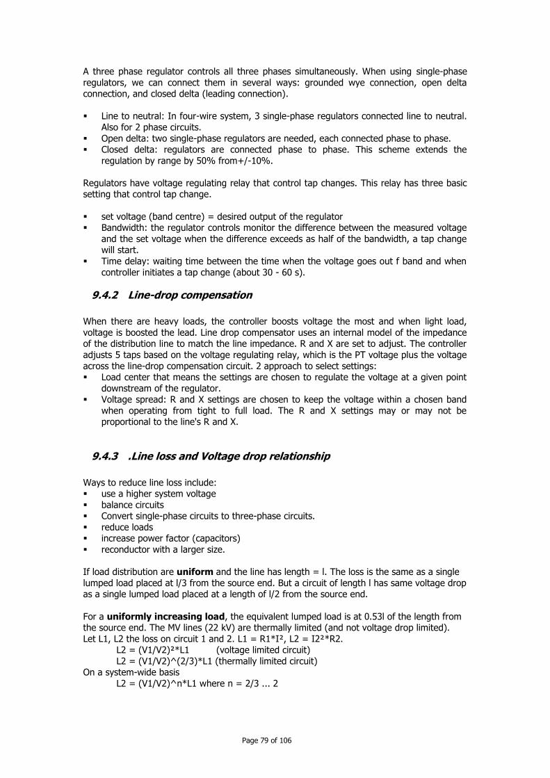
Page 79 of 106
A three phase regulator controls all three phases simultaneously. When using single-phase
regulators, we can connect them in several ways: grounded wye connection, open delta connection, and closed delta (leading connection).
Line to neutral: In four-wire system, 3 single-phase regulators connected line to neutral.
Also for 2 phase circuits.
Open delta: two single-phase regulators are needed, each connected phase to phase. Closed delta: regulators are connected phase to phase. This scheme extends the
regulation by range by 50% from+/-10%.
Regulators have voltage regulating relay that control tap changes. This relay has three basic setting that control tap change.
set voltage (band centre) = desired output of the regulator Bandwidth: the regulator controls monitor the difference between the measured voltage
and the set voltage when the difference exceeds as half of the bandwidth, a tap change will start.
Time delay: waiting time between the time when the voltage goes out f band and when
controller initiates a tap change (about 30 - 60 s).
9.4.2 Line-drop compensation
When there are heavy loads, the controller boosts voltage the most and when light load,
voltage is boosted the lead. Line drop compensator uses an internal model of the impedance of the distribution line to match the line impedance. R and X are set to adjust. The controller
adjusts 5 taps based on the voltage regulating relay, which is the PT voltage plus the voltage
across the line-drop compensation circuit. 2 approach to select settings: Load center that means the settings are chosen to regulate the voltage at a given point
downstream of the regulator. Voltage spread: R and X settings are chosen to keep the voltage within a chosen band
when operating from tight to full load. The R and X settings may or may not be proportional to the line's R and X.
9.4.3 .Line loss and Voltage drop relationship
Ways to reduce line loss include: use a higher system voltage
balance circuits Convert single-phase circuits to three-phase circuits.
reduce loads increase power factor (capacitors)
reconductor with a larger size.
If load distribution are uniform and the line has length = l. The loss is the same as a single
lumped load placed at l/3 from the source end. But a circuit of length l has same voltage drop as a single lumped load placed at a length of l/2 from the source end.
For a uniformly increasing load, the equivalent lumped load is at 0.53l of the length from the source end. The MV lines (22 kV) are thermally limited (and not voltage drop limited).
Let L1, L2 the loss on circuit 1 and 2. L1 = R1*I², L2 = I2²*R2. L2 = (V1/V2)²*L1 (voltage limited circuit)
L2 = (V1/V2)^(2/3)*L1 (thermally limited circuit) On a system-wide basis
L2 = (V1/V2)^n*L1 where n = 2/3 ... 2
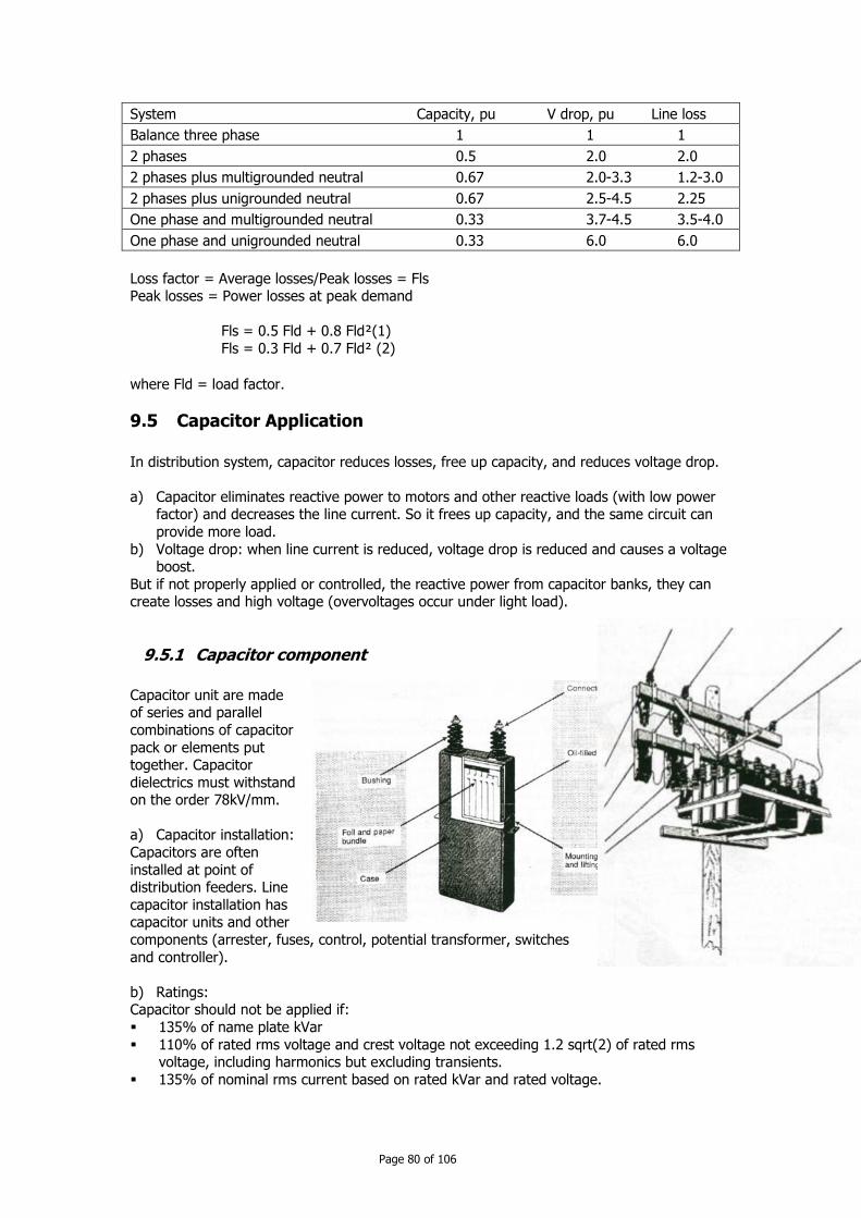
Page 80 of 106
System Capacity, pu V drop, pu Line loss
Balance three phase 1 1 1
2 phases 0.5 2.0 2.0
2 phases plus multigrounded neutral 0.67 2.0-3.3 1.2-3.0
2 phases plus unigrounded neutral 0.67 2.5-4.5 2.25
One phase and multigrounded neutral 0.33 3.7-4.5 3.5-4.0
One phase and unigrounded neutral 0.33 6.0 6.0
Loss factor = Average losses/Peak losses = Fls Peak losses = Power losses at peak demand
Fls = 0.5 Fld + 0.8 Fld²(1)
Fls = 0.3 Fld + 0.7 Fld² (2)
where Fld = load factor.
9.5 Capacitor Application
In distribution system, capacitor reduces losses, free up capacity, and reduces voltage drop.
a) Capacitor eliminates reactive power to motors and other reactive loads (with low power factor) and decreases the line current. So it frees up capacity, and the same circuit can
provide more load.
b) Voltage drop: when line current is reduced, voltage drop is reduced and causes a voltage boost.
But if not properly applied or controlled, the reactive power from capacitor banks, they can create losses and high voltage (overvoltages occur under light load).
9.5.1 Capacitor component
Capacitor unit are made of series and parallel
combinations of capacitor
pack or elements put together. Capacitor
dielectrics must withstand on the order 78kV/mm.
a) Capacitor installation:
Capacitors are often
installed at point of distribution feeders. Line
capacitor installation has capacitor units and other
components (arrester, fuses, control, potential transformer, switches
and controller).
b) Ratings: Capacitor should not be applied if:
135% of name plate kVar
110% of rated rms voltage and crest voltage not exceeding 1.2 sqrt(2) of rated rms voltage, including harmonics but excluding transients.
135% of nominal rms current based on rated kVar and rated voltage.
Page 81 of 106
Capacitor should withstand various peak voltage and current transients. See table.
Probable numbers Permissible peak transient Permissible peak transient
of transient per year current (multiplying factor) voltage (multiplying factor)
4 1500 5.0
40 1150 4.0
400 800 3.4
c) Capacitance (in microfarad)
C µF = 2.65QkVar/Vkv²
Where Vkv = capacitor voltage rating kV
QkVar = unit reactive power rating, kVar d) Resistor
The resistor must be low enough so RC time constant can decay in 300 seconds.
50/sqrt(s)V <= exp(-300/RC) V = capacitor voltage rating V
R: discharge resistor, ohm C: capacitance, F
e) Discharged power:
Power discharged by resistor P (watts) = (Q kVAr/113.2)* ln(35.36/V)
f) Environment Capacitor does not have load cycles; they are always at full load. Capacitor have to operate
from 40 to46 degree C with unrestricted ventilation and direct sunlight. Minimum temperature
of air is about -40 degree C.
g) Release capacity Extra capacity as a function of the size of capacitor and original power factor.
P extra = (-20 PF orig + (PF corrected - 0.5)*120)%
h) Voltage support
I = I rated * V pu Q kVar = Q rated (V pu)^2
i) Reducing line loss
Using capacitor to supply reactive power reduces the amount of current in the line. So
reducing the reactive power flow on line significantly reduces losses.
9.6 Sizing and placing capacitor
There is 2/3 rule for sizing and placing capacitor to optimally reduce losses.
For uniformly distributed load, the optimal size of capacitor is 2/3 of the var requirement of the circuit. The optimal placement of this capacitor is 2/3 of the distance from the substation
to the end of line.
If using n capacitor, so
Q rated = 2/(2n+1) Q var required Location at 2/(2n+1).i.L where i is the number of capacitor
Method Gransgel and Lee (1981) using 1/2kVar rule.
1) Pick a size
Choose a standard size capacitor Q rated 0. If Q rated = 2/3 Q var required, so only 1 bank.

Page 82 of 106
Else Q rated = 1/6 Q var required and then use 5 banks
2) Locate first bank Start from the end of line.
Find point where Q va = 1/2 Q rated 3) Locate subsequent banks
Reevaluate the var profile. Move upstream until the point where var flow = 1/2 Q rated
But under light load check that the capacitors have not raised the voltages above allowable standards If V > Vlimits ( V + 10%) reduce the size of the capacitor banks or
the number of capacitor banks until voltage limits are not exceeded.
9.6.1 Energy losses
Use the average reactive loading profile to optimally size and place capacitor for energy
losses. For peak load, use 1/2 kVar method.
For average reactive load, use 1/2 kVar method or the 2/3 rule to optimize energy losses.
If we do not have average system case, we can use reactive load factor RLF. RLF = Average kVar demanded / Peak kVar demanded.
9.6.2 Switched Banks
Benefit of switched banks in situations:
more loss reduction: we switch banks on and off to track these changes. voltage limits: when apply banks under average loading scenario cause excessive voltage
under light load, so use switched banks.
9.6.3 Sizing and placing switched banks
We can use 1/2 kVar method and determine the on time and off time and determine the proper sizing based on the average reactive flow between the on and off times.
9.6.4 Combinations of fixed and switched banks
Apply fixed banks to the circuit with 1/2 kVar rule based on the light load case.
Check voltage. If undervoltage, so increase the size of capacitor or use more capacitor banks or add regulators.
Look for location suitable for switched banks. Use average reactive line flows for the time when the capacitor is on. Apply switched capacitors, check the light load case for
possible overvoltages, and check peak-load for undervoltage.
9.7 Controls
Several options for controls are available for capacitor banks: Time clock: switch capacitor on and off based on the time of the day
Temperature: switch capacitor on and off depended on the temperature of the capacitor
Voltage: switch the capacitor on and off based on voltage. vars: the capacitor uses var measurement to determine switching
power factor: similar to var control, the controller switch capacitor on and off based on the measured power factor.
current: The capacitor switches on and off based on the line current (as measured
downstream of the capacitor).
Page 83 of 106
9.8 Failure modes
9.8.1 Low current and progressive failure
The dielectric fails is one of the elements within the capacitor. If one element is shorted,
voltage on remaining elements increases, so higher current is. Another element may short
out because of more voltage stress. Failure can cascade until the whole string short out. Fuse must be very sensitive.
High current: a low impedance failure develops across the capacitor terminals or from a
phase terminal to ground. A broken connection could cause such a fault.
9.8.2 Fusing and protection
Purpose: clear a fault if a capacitor unit or any of the accessories fail. Problem: a fuse is blown, but the capacitors themselves are still functional. So unbalance
voltage increases and can also increase stray voltages, and so increase losses. Selection of fuse size: 1.25 and 1.35 times rule. 3 factors can contribute to higher than
expected current.
Overvoltage: I capacitor is proportional to capacitor voltage, but Q var is proportional to square V. So upper voltage limit of 110% is normally use.
Harmonics: Capacitor is a sink for harmonics. Increase the peak and rms of the current through the capacitor. Grounded three-phase banks absorb zero sequence harmonics
from the system.
Capacitor tolerance: +15% above their ratings (so increase current by 15%)
Smallest size of fuse: Use tight-fusing approach, with tin link
I min = 1.35 I1 / 1.5 = 0.9 I1 where
I1 = capacitor bank current, A
Imin = minimum fuse rating 1.5 is for overload
9.8.3 Nuisance fuse operations
Lightning: Capacitors are low impedance to the high frequency lightning surge, so they attract lightning current, which can blow fuse. Rule of thumb: fuse should > 20K or 15T
Outrush to nearby faults: Capacitor may dump its stored charge into a nearby fault, the fuse could blow. Capacitor banks also have inrush every time they are switched in, but
this is well below the melt point of the fuse.
Outrush may be worse with two factors:
a) Higher system voltage. Higher voltage capacitor bank use smaller fuses with loss I^2 *t capability.
b) Larger conductors (because conductor has low resistance).
Sever harmonics. Harmonics increase the current through the fuse.
Animal or other bushing faults. A fault across a bushing due to an animal, contamination on the bushing or tree contact can blow a fuse. Use animal guards and covered jumpers
to reduce these. Mechanical damage and deterioration
Corrosion and vibration can weaken fuse links (not so much problem of this kind)
Installation errors: Fuses are more likely to blow if crews put in the wrong size fuse or wrong type fuse or do not properly tighten the braid on the fuse.

Page 84 of 106
CChhaapptteerr 1100:: OOppeerraattiioonn aanndd MMaaiinntteennaannccee
10 Operation and maintenance
10.1 Repair and maintenance
Repair is action aimed to liquidate the cause of a fault and restore the initial state of
equipment. Maintenance is preventive action aimed to prevent a cause of fault not to occurs, so the equipment could operate continuously. That means maintenance is activities aimed to
maintain the equipment in normal state of operation. The maintenance tends to eliminate the repair activities.
10.2 Maintenance service
The maintenance service is responsible in the prevention of any power outage and prevents any possible accidents.
10.3 Study function
a) Technical study in order to elaborate base of technical documentation of maintenance.
b) Prepare order and instructions: this is the core of maintenance operation. c) Cost study: study the procurement and analyse maintenance cost and damage cost in
order to consider the efficiency of the maintenance service. d) Executive function
This function is realized by a team of many specialized workers and technicians (mechanical,
electrical domain) e) Methodology
Preventive maintenance Corrective maintenance
f) Maintenance tasks
Fault liquidation major repairs
Maintenance service
Maintenance policy Research function
Technical study
Inventory of materials
Technical files Improvements
Rehabilitation
Documentations
Maintenance
Intervention Planning
Monitoring records Spare parts
Cost study
Maintenance cost Damage cost
Execution
Repair or preventive repair, improvement, fault liquidation and repair
Report
Executive function

Page 85 of 106
Inspection
Revision Standard compliance
g) Maintenance documentations Technical documentation
History
Monitoring card Correction card
h) Conclusion

Page 86 of 106
CChhaapptteerr 1111:: DDeessiiggnn ooff aann EElleeccttrriiccaall NNeettwwoorrkk
11 Design of aerial electrical network conforming to Electric Power Technical Standard of the Kingdom of Cambodia
11.1 Formal standards, rules and regulations
All technical designs for MV installation need to comply with:
The Electrical Power Technical Standards of Cambodia – Charpter 4: Medium and
Low voltage distribution facilities - Printed by EAC dated August 2007,
11.2 Basic Calculation
The calculation of wind load
Wind Load <Wind Load to 1m2>
2
2
1VCP [N]
P : Wind Load to 1m2 [Pa]
C : Resistance coefficient δ : Density of Air(kg/m3)
V : Wind Speed(m/sec)
V adopted in GREPTS is 32m/sec, that is derived from the observation data in Kingdom of Cambodia.
<Example 1 (for conductor)> V=32m/sec, C=1.05, δ=1.137kg/m3
P=1.05×1/2×1.137×322 =611(Pa)
10% margin is taken into consideration Maximum design wind Load for Conductors → 680(Pa)
<Example 2 (for wooden pole)>
V=32m/sec, C=1.2, δ=1.137kg/m3 P=0.8×1/2×1.137×322=466 Pa
10% margin is taken into consideration Maximum design wind Load for Wooden Pole → 520(Pa)
Table : Wind load (to 1m2)
Segment of an object receiving wind pressure Wind pressure to 1m2 of the vertical projected area
(Pa)
Supporting structure
Wooden pole Columnar pole 520
Iron-reinforced concrete pole
Columnar pole 520
Square pole 1,290
Electrical conductor and other strung conductor 680
The calculation of tension of overhead distribution conductors
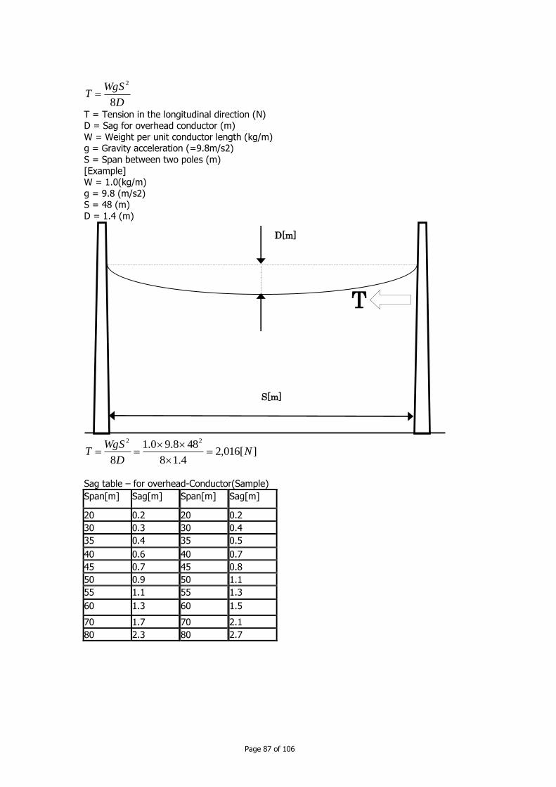
Page 87 of 106
D
WgST
8
2
T = Tension in the longitudinal direction (N) D = Sag for overhead conductor (m)
W = Weight per unit conductor length (kg/m) g = Gravity acceleration (=9.8m/s2)
S = Span between two poles (m)
[Example] W = 1.0(kg/m)
g = 9.8 (m/s2) S = 48 (m)
D = 1.4 (m)
][016,24.18
488.90.1
8
22
ND
WgST
Sag table – for overhead-Conductor(Sample)
Span[m] Sag[m] Span[m] Sag[m]
20 0.2 20 0.2
30 0.3 30 0.4
35 0.4 35 0.5
40 0.6 40 0.7
45 0.7 45 0.8
50 0.9 50 1.1
55 1.1 55 1.3
60 1.3 60 1.5
70 1.7 70 2.1
80 2.3 80 2.7
S[m]
D[m]
T
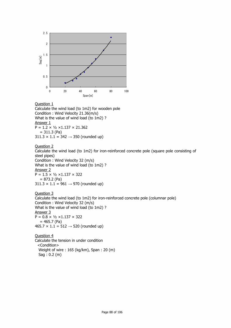
Page 88 of 106
Question 1 Calculate the wind load (to 1m2) for wooden pole
Condition : Wind Velocity 21.36(m/s) What is the value of wind load (to 1m2) ?
Answer 1
P = 1.2 × ½ ×1.137 × 21.362 = 311.3 (Pa) 311.3 × 1.1 = 342 → 350 (rounded up)
Question 2 Calculate the wind load (to 1m2) for iron-reinforced concrete pole (square pole consisting of
steel pipes) Condition : Wind Velocity 32 (m/s)
What is the value of wind load (to 1m2) ?
Answer 2 P = 1.5 × ½ ×1.137 × 322
= 873.2 (Pa) 311.3 × 1.1 = 961 → 970 (rounded up)
Question 3
Calculate the wind load (to 1m2) for iron-reinforced concrete pole (columnar pole)
Condition : Wind Velocity 32 (m/s) What is the value of wind load (to 1m2) ?
Answer 3 P = 0.8 × ½ ×1.137 × 322
= 465.7 (Pa) 465.7 × 1.1 = 512 → 520 (rounded up)
Question 4
Calculate the tension in under condition
<Condition> Weight of wire : 165 (kg/km), Span : 20 (m)
Sag : 0.2 (m)
0
0.5
1
1.5
2
2.5
0 20 40 60 80 100
Span[m]
Sag[m]

Page 89 of 106
Answer 4 T = (0.165 × 9.8 × 202)/(8 × 0.2)
= 404.3 (N)
Question 5
Calculate the tension in under condition <Condition>
Weight of wire : 435 (kg/km), Span : 80 (m)
Sag : 2.7 (m) Answer 5
T = (0.435 × 9.8 × 802)/(8 × 2.7) = 1263.1 (N)
6.2Typical Assembling of Distribution Facilities
<Mitigate Case>
<Usual Case>
20[m]
0.2[m]
T
0.15[m]
D(sag)[m]
< 0.85[m]
1[m]
MV or LV
0.15[m]
D(sag)[m] < 0.95[m]
Height from the ground 3[m]
0.9[m]
MV or LV
Length of supporting structure
5[m] Length of supporting structure
6[m]

Page 90 of 106
How many meters should we use the pole?
0.15[m]
D(sag)[m] < 1.65[m]
1.7[m]
MV or LV 0.15[m]
D(sag)[m] < 0.85[m]
Height from the ground
6.5[m]
1.5[m]
MV or LV
Length of supporting structure 9[m]
Length of supporting structure 10[m]
0.15[m]
D(sag)[m] < 1.65[m]
1.7[m]
MV or LV 0.15[m]
D(sag)[m] < 0.85[m]
Height from the ground 6.5[m]
1.5[m]
MV or LV
Length of supporting structure 9[m]
Length of supporting structure 10[m]
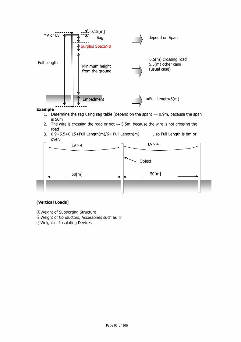
Page 91 of 106
Example
1. Determine the sag using sag table (depend on the span) → 0.9m, because the span
is 50m 2. The wire is crossing the road or not → 5.5m, because the wire is not crossing the
road
3. 0.9+5.5+0.15+Full Length(m)/6<Full Length(m) , so Full Length is 8m or
over.
[Vertical Loads]
①Weight of Supporting Structure
②Weight of Conductors, Accessories such as Tr
③Weight of Insulating Devices
0.15[m]
Sag
Minimum height from the ground
Embedment
MV or LV
Full Length
Surplus Space>0
=Full Length/6(m)
=6.5(m) crossing road
5.5(m) other case
(usual case)
depend on Span
50[m] 50[m]
Object
LV×4 LV×4

Page 92 of 106
[Horizontal transverse Loads]
①Wind Load of Supporting Structure
②Wind Load of Conductors, GW
③Wind Load of Insulators, Fittings
④Horizontal Transverse Component of
the maximum tension of Conductors [Horizontal longitudinal Loads]
①Wind Load of Supporting Structure
②,②’ Horizontal Transverse Component of
the maximum tension of Conductors
6.3Calculation of the Strength of Supporting Structure
Calculation of Strength of Wooden Poles
Bending moment due to Wind Load of Supporting Structures
H H
L dxxkxDKdWx
Mp0 0
01
100100
32100
32
01 kHHDKMp
K1 : Wind load per 1m2 of wooden pole (N/m2)
D0 : The diameter of the pole at the surface of the ground (=D+kH) (cm) H : The height of the pole above the ground (m)
k : The increase rate of the diameter of the wooden pole (cm/m) (=0.9)
D : The diameter of the top of the pole (cm) Bending moment due to wind Load of Conductors
10001000
22
dhSKhS
dKMw
K2:Wind load per 1m2 vertically projected area of the distribution conductors (N/m2)
d : diameter of the conductor (mm) S : A half of the spans on the both sides (m)
h : Height of the supported position of the conductor (m)
The allowable stress of wooden poles
①+②+③
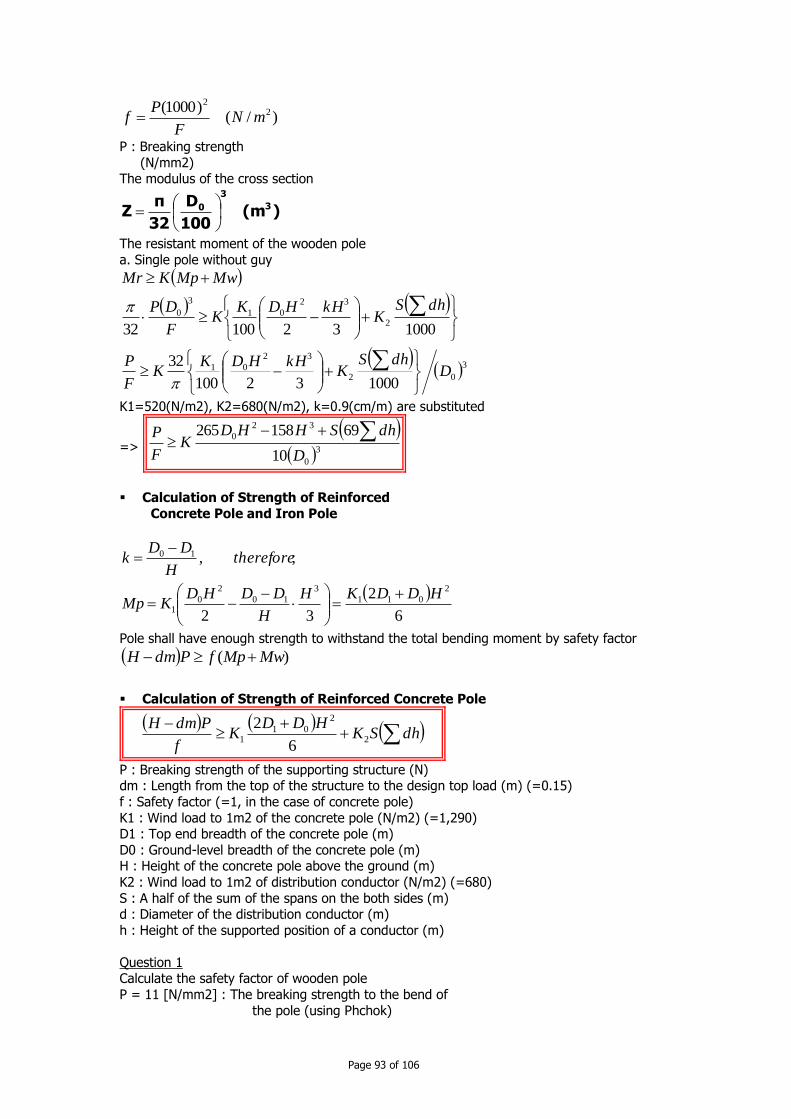
Page 93 of 106
)/()1000( 2
2
mNF
Pf
P : Breaking strength
(N/mm2) The modulus of the cross section
)(m100
D
32
πZ 3
3
0
The resistant moment of the wooden pole
a. Single pole without guy
302
32
01
2
32
01
3
0
100032100
32
10003210032
DdhS
KkHHDK
KF
P
dhSK
kHHDKK
F
DP
MwMpKMr
K1=520(N/m2), K2=680(N/m2), k=0.9(cm/m) are substituted
=>
30
32
0
10
69158265
D
dhSHHDK
F
P
Calculation of Strength of Reinforced
Concrete Pole and Iron Pole
6
2
32
;,
2
011
3
10
2
01
10
HDDKH
H
DDHDKMp
thereforeH
DDk
Pole shall have enough strength to withstand the total bending moment by safety factor
)( MwMpfPdmH
Calculation of Strength of Reinforced Concrete Pole
dhSKHDD
Kf
PdmH2
2
011
6
2
P : Breaking strength of the supporting structure (N) dm : Length from the top of the structure to the design top load (m) (=0.15)
f : Safety factor (=1, in the case of concrete pole)
K1 : Wind load to 1m2 of the concrete pole (N/m2) (=1,290) D1 : Top end breadth of the concrete pole (m)
D0 : Ground-level breadth of the concrete pole (m) H : Height of the concrete pole above the ground (m)
K2 : Wind load to 1m2 of distribution conductor (N/m2) (=680)
S : A half of the sum of the spans on the both sides (m) d : Diameter of the distribution conductor (m)
h : Height of the supported position of a conductor (m)
Question 1 Calculate the safety factor of wooden pole
P = 11 [N/mm2] : The breaking strength to the bend of
the pole (using Phchok)

Page 94 of 106
K = 1 : constant
D0 = 12 [cm] : The diameter of the pole at the surface of the ground
H = 6 [m] : The height of the pole above the ground (the length of pole = 7 [m])
S = 50 [m] : span
d = 0.0074 [m] : The outer diameter of each wire h = 5.85 [m] : The height of the supporting point of each
wire above the ground
Answer 1
30
32
0
10
69158265
D
dhSHHDK
F
P
FF
P 11
D(sag)[m]
Height of the pole above the ground 6 [m]
1 [m]
LV×4wire
Length of supporting structure 7[m]
Height of the supporting point above the ground 5.85 [m]
50[m] 50[m]
Object
LV×4 LV×4
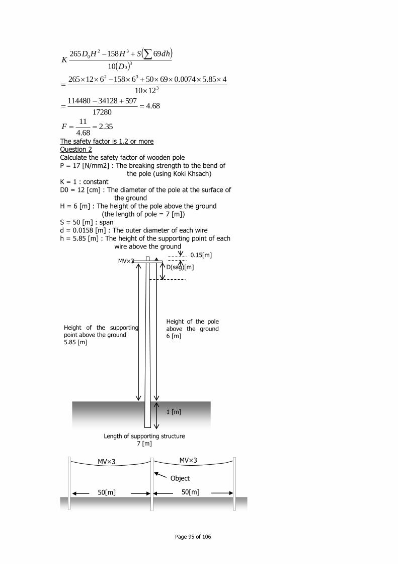
Page 95 of 106
68.417280
59734128114480
1210
485.50074.069506158612265
10
69158265
3
32
30
32
0
D
dhSHHDK
35.268.4
11F
The safety factor is 1.2 or more Question 2
Calculate the safety factor of wooden pole
P = 17 [N/mm2] : The breaking strength to the bend of the pole (using Koki Khsach)
K = 1 : constant D0 = 12 [cm] : The diameter of the pole at the surface of
the ground
H = 6 [m] : The height of the pole above the ground (the length of pole = 7 [m])
S = 50 [m] : span d = 0.0158 [m] : The outer diameter of each wire
h = 5.85 [m] : The height of the supporting point of each wire above the ground
0.15[m]
D(sag)[m]
Height of the pole above the ground 6 [m]
1 [m]
MV×3
Length of supporting structure
7 [m]
Height of the supporting point above the ground 5.85 [m]
50[m] 50[m]
Object
MV×3 MV×3
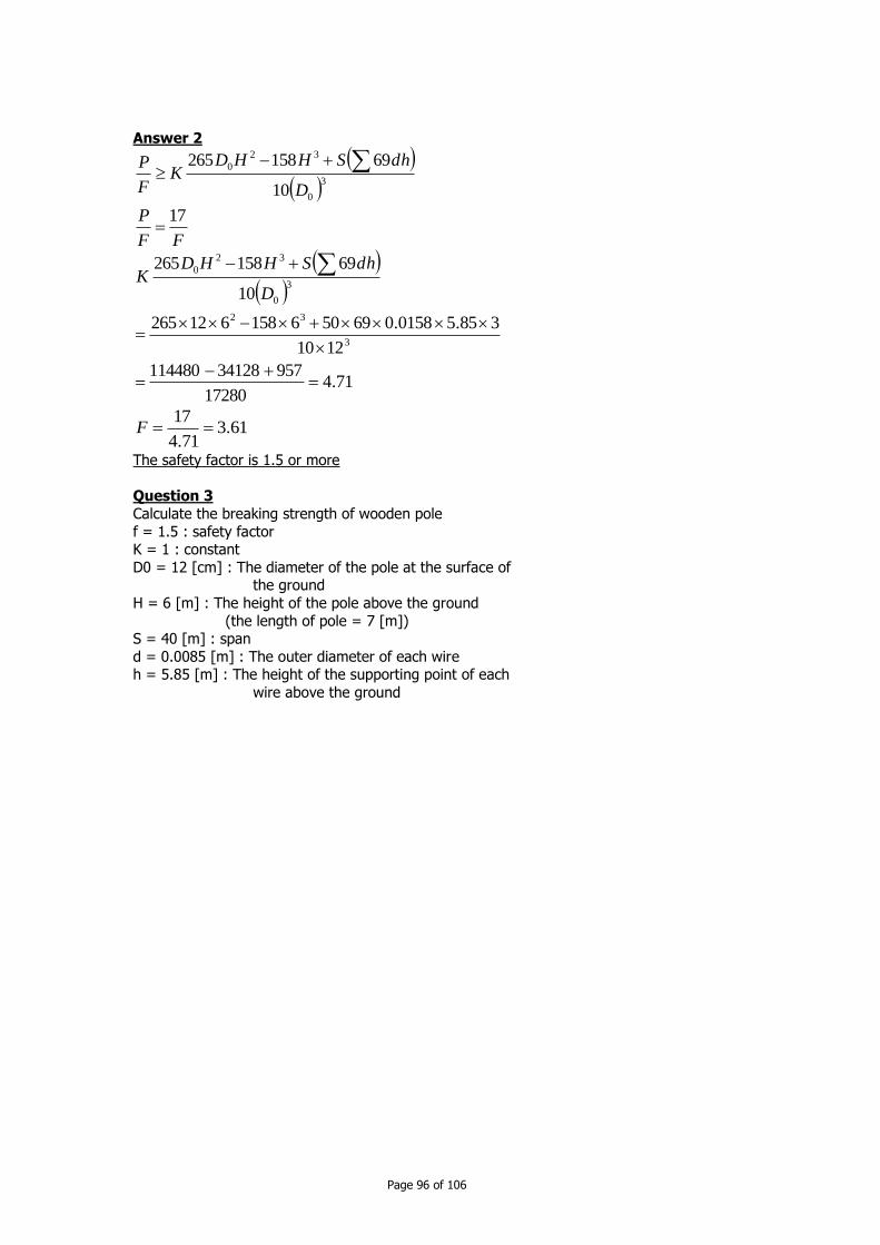
Page 96 of 106
Answer 2
30
32
0
10
69158265
D
dhSHHDK
F
P
FF
P 17
71.417280
95734128114480
1210
385.50158.069506158612265
10
69158265
3
32
3
0
32
0
D
dhSHHDK
61.371.4
17F
The safety factor is 1.5 or more
Question 3
Calculate the breaking strength of wooden pole
f = 1.5 : safety factor K = 1 : constant
D0 = 12 [cm] : The diameter of the pole at the surface of the ground
H = 6 [m] : The height of the pole above the ground
(the length of pole = 7 [m]) S = 40 [m] : span
d = 0.0085 [m] : The outer diameter of each wire h = 5.85 [m] : The height of the supporting point of each
wire above the ground

Page 97 of 106
Answer 3
30
32
0
3
0
32
0
10
69158265
10
69158265
D
dhSHHDFKP
D
dhSHHDK
F
P
7
7
17280
412341281144805.1
1210
385.50085.06940615861226515.1
10
69158265
3
32
3
0
32
0
P
D
dhSHHDFK
…so we can use Phchok, Koki Khsach, Thbaeng and Khlong.
Question 4
Calculate the safety factor of concrete pole H = 7.5 [m] : The height of the pole above the ground
0.15[m]
D(sag)[m]
Height of the pole above the ground 6 [m]
1 [m]
MV×3
Length of supporting structure 7 [m]
Height of the supporting point above the ground 5.85 [m]
40[m] 40[m]
Object
MV×3 MV×3

Page 98 of 106
dm = 0.15 [m] : length from the top of the structure to the
design top load P = 4×10³ [N] : breaking load of the supporting structure
K1 = 1290 [Pa] : wind pressure to 1m2 of the vertical projected area (square pole)
D1 = 0.13 [m] : top end breadth
D0 = 0.23 [m] : ground level breadth K2 = 680 [Pa] : wind pressure to 1m2 of the vertical
projected area (conductor) S = 50 [m] : span
d = 0.0078 [m] : outer diameter of each wire h = 7.31 [m] : height of the supporting point of
each wire above the ground
Answer 4
dhSKHDD
Kf
PdH m2
2
011
6
2
fff
PdH m 2940010415.05.7 3
5926
6
5.723.013.021290
6
2 22
011
HDDK
0.15[m]
Height of the pole above the ground 7.5 [m]
1.5 [m]
LV×3
Length of supporting structure 9 [m]
Height of the supporting point above the ground 7.31 [m]
50[m] 50[m]
Object
LV×3 LV×3
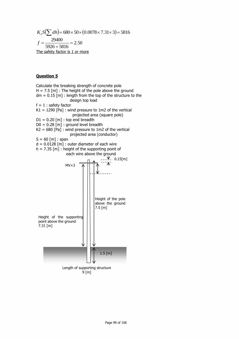
Page 99 of 106
5816331.70078.0506802 dhSK
50.258165926
29400
f
The safety factor is 1 or more
Question 5
Calculate the breaking strength of concrete pole
H = 7.5 [m] : The height of the pole above the ground dm = 0.15 [m] : length from the top of the structure to the
design top load
f = 1 : safety factor K1 = 1290 [Pa] : wind pressure to 1m2 of the vertical
projected area (square pole) D1 = 0.20 [m] : top end breadth
D0 = 0.28 [m] : ground level breadth
K2 = 680 [Pa] : wind pressure to 1m2 of the vertical projected area (conductor)
S = 60 [m] : span d = 0.0128 [m] : outer diameter of each wire
h = 7.35 [m] : height of the supporting point of
each wire above the ground
0.15[m]
Height of the pole above the ground 7.5 [m]
1.5 [m]
MV×3
Length of supporting structure 9 [m]
Height of the supporting point above the ground 7.31 [m]

Page 100 of 106
Answer 5
dhSKHDD
KdH
fP
dhSKHDD
Kf
PdH
m
m
2
2
011
2
2
011
6
2
6
2
136.015.05.7
1
mdH
f
8224
6
5.728.020.021290
6
2 22
011
HDDK
11515335.70128.0606802 dhSK
…so we can use the concrete pole that has 2.7kN or more strength.
Calculation of the Strength of Foundation of Supporting Structure
If the soil isn’t soft and the supporting structure is set under the below conditions, you don’t
have to calculate the strength of foundations of supporting structure.
Design Load of
Supporting
Structure
The Total Length
of Supporting
Structure
Embedment
15m or less 1/6 or more of total
15m - 16m 2.5m or more
15m or less 1/6 or more of total
15m - 16m 2.5m or more
15m or less 1/6 or more of total
15m - 16m 2.5m or more
16m - 20m 2.8m or more
Wooden
Pole
Iron Pole
Iron-
reinforced
Concrete
Pole
-
-
6.5kN or less
60[m] 60[m]
Object
MV×3 MV×3
][7.2
][2685115158224136.0
kNP
NP

Page 101 of 106
CChhaapptteerr 1122:: EEaarrtthhiinngg aanndd SSaaffeettyy
12 Earthing and safety
Grounding is a mean to defense against hazardous electric shocks and hazardous overvoltage. There are equipment grounding and system grounding. Equipment grounding
helps reduce the chances that people get shocks from internal failures of the equipment.
System grounding determines how loads are connected and how line-to-ground faults are clears.
12.1 System Grounding Configuration
12.1.1 Four wire multi-grounded systems
Advantages: Low cost serving single-phase loads because:
single cable for underground single-phase load Single-phase overhead lines are less expensive
single-bushing transformers
One arrester and one fuse for a single-phase transformer. the neutral can be located lower on the pole
Lower rated arresters lower insulation required
Use of single-phase lines provides cost savings. The primary neutral may be shared with the
secondary neutral for further cost savings. Flexibility in upgrading a single-phase line to two-
or three phase service on overhead lines following load growth should be done.
Safety is good. If a transformer pole-ground down lead gets broken, little safety margin is lost. A low-impedance path to earth protect against internal faults in the transformer.
A grounding transformer must not be disconnected during operation of the distribution line,
because a single-line-to-ground fault causes high overvoltages on the unfaulted phases and
load unbalances may create overvoltage.
12.1.2 Three wire system, either grounded or ungrounded
An ungrounded is grounded at one place, normally the substation.
Three wire systems have following advantages:

Page 102 of 106
lower cost for three-phase loads
lower stray voltage easier detection of high-impedance faults
lower magnetic fields
12.2 Single-wire earth return
The earth carries all of the return current. On earth-return systems, the resistance of ground electrodes is critical. Poor ground connections can cause low end-use voltage and can create
dangerous step-and-touch potentials to the transformer tank.
12.2.1 High resistance grounding and high reactance grounding
This grounding is rarely used in distribution system. The main advantage is that it can operate with one phase fault.
12.3 Neutral shift during ground fault
The system grounding determines the overvoltages that can arise during a line-to-ground fault. A single line-to-ground fault shifts the ground potential at the fault location. If system is
grounded solidly with a good return path to the grounding source, a little reference shift occurs. For the wye configuration, the fault shift ground potential to phase voltage. The line-
to-ground voltage on the unfaulted phases rises to the line-to-line voltage, 1.73 per unit. For
multigrounded system with a solidly grounded station transformer, overvoltage above 1.3 per unit is rare.
12.3.1 Neutral shift on multigrounded systems
Overvoltage is highest for faults near the substation.
Overvoltage is higher on shorter feeders A large neutral provides a better return path.
More ground rods and lower rod resistance reduce overvoltage A neutral reactor on the substation transformer causes a higher overvoltage mainly for
faults near the station.
12.3.2 Overvoltage on Ungrounded systems
Ungrounded systems may have extra-high overvoltages under certain conditions:
Resonance- the line-to-ground capacitance can resonate with the system reactance. Arcing ground faults-a restriking ground fault can create significant line-to-ground
voltage.
This overvoltage affects the insulation and arresters (so higher arresters are necessary). A bolted line-to-ground fault on one phase draws very little current on ungrounded system, so
the system can continue to operate.
12.4 Equipment grounding
Effective grounds are required for: surge arresters
primary, secondary, and common neutrals unguarded metal or metal-reinforced supporting structures
other intentionally ground wires instrument transformers
cable cocentric neutrals

Page 103 of 106
most equipment including transformers, capacitors, regulators, reclosers, and
sectionalizers. uninsulated guy
customer meters.
12.4.1 Ungrounded system of customer
If the transformer fails from the primary to secondary or high-to-low fault, the secondary grounding system must be effective enough to prevent unsafe voltage on customer wiring.
The distribution transformer, customer meter are grounded as well as possible.
The primary surge arrester shall be separated from the secondary ground through a spark
gap, which breaks down at least twice the primary circuit voltage but <= 10 kV.
12.4.2 Secondary grounding problem
If the neutral is open (has poor connection), the unbalanced current must return through the
grounding electrodes (may have high impedance). It may happen light flicker, and high voltage on the less loaded of the secondary legs.
If the load is connected to equipment grounded and not to neutral, or ground wire is connected wrongly to neutral anywhere in customer facility, current flowing in the grounding
conductor wire increases shock hazards. Other problems are isolated grounding, ground loop and missing safety grounds.
12.5 Grounding electrodes
Ground rod is the most common grounding electrodes. The length of the rod is 1.5m. If a
driven rod hits a rock bottom, the rod should be to drive at an angle or to use another type of ground.
The resistance of a ground rod is:
R = (rho/2 pi Ll)(ln(4L/a -1)
Where rho = soil resistivity ohm/m
L = length of the ground rod, m
a = radius of the ground rod, m Rod diameter is needed for mechanical strength and to survive corrosion.
The rod is better driven deeper is the soil has low resistivity at lower levels. Multiple ground rods in parallel reduce resistance, but they must be not to close to each
other.
Resistance of multiple rods
Number of rods Multiplying factor Total resistance % of one rod
2 1.16 58%
3 1.29 43%
4 1.36 34%
8 1.68 21%
12 1.80 15%
16 1.92 12%
20 2.00 10%
24 2.16 9%
Water piping is allowed to be used as ground, but gas piping is not allowed.

Page 104 of 106
Other type of ground may be buried wires, strips, and plates.
Buried wires must have at least 4mm diameter, at least 3m long and 0.45m deep. Strips must have at least 3m long, buried at least 0.45m deep, and have total surface
area on both sides of 0.47m2. Plates must be buried at least 1.5m deep and have a total surface area of at least
0.185m2.
Both plates and strips must have a thickness of at least 1.5mm wde for nonferrous metals and at least 6mm wide for ferrous metals.
12.5.1 Soil characteristics
Soil resistivity varies widely.
Soil Average resistivity resistance of 16mm diameter
ohm-m and 3m length rod
well graded gravel, gravel-sand mix 600-1000 180-300
poorly graded gravel 1000-2500 300-750
clayey gravel, sand-clay mixture 200-400 60-120
Silty, sands, poorly graded
sand-silts mixtures 100-500 30-350
Clayey sands, poorly graded
sand-clay mixture 50-200 15-60
Silty and clayey fine sands 30-80 9-24
Fine sandy or silty soil, elastic silt 80-300 24-90
Gravelly clays, sandy clays, silty clays 25-60 17-18
Inorganic clays or high plasticity 10-55 3-16
Source IEEE Std. 142-1991
Soil resistivity often varies with depth because in most case as moisture increases with depth.
In this case resistivity decreases significantly with depth. Underlying bedrock significantly
increases resistivity at lower levels. Several different layers of soil with different resistivities may be present.
Soil resistivity is affected by moisture (dryer the soil, higher the resistivity), temperature and
salts.
We can use chemical treatments or backfills to reduce the soil resistivity near the electrode.
Be careful with the chemical treatments, because this increase rod corrosion.
The ground current will dry the soil and degrade ground resistance. High voltage stress and high current from lightning or fault degrade ground resistance by breakdown the soil.
12.5.2 Corrosion
Ground electrodes may be copper-clad steel or galvanized steel. Steel and aluminium corrode
quickly for grounding use. Copper may be stolen.
Mixing metals increases corrosion (galvanic corrosion). Different metals create an
elctrochemical battery in the soil. Galvanic corrosion between dissimilar metals can eat up grounding electrodes.
Copper has good properties that limit corrosion, because the copper oxyde layer greatly reduces the corrosion rate.
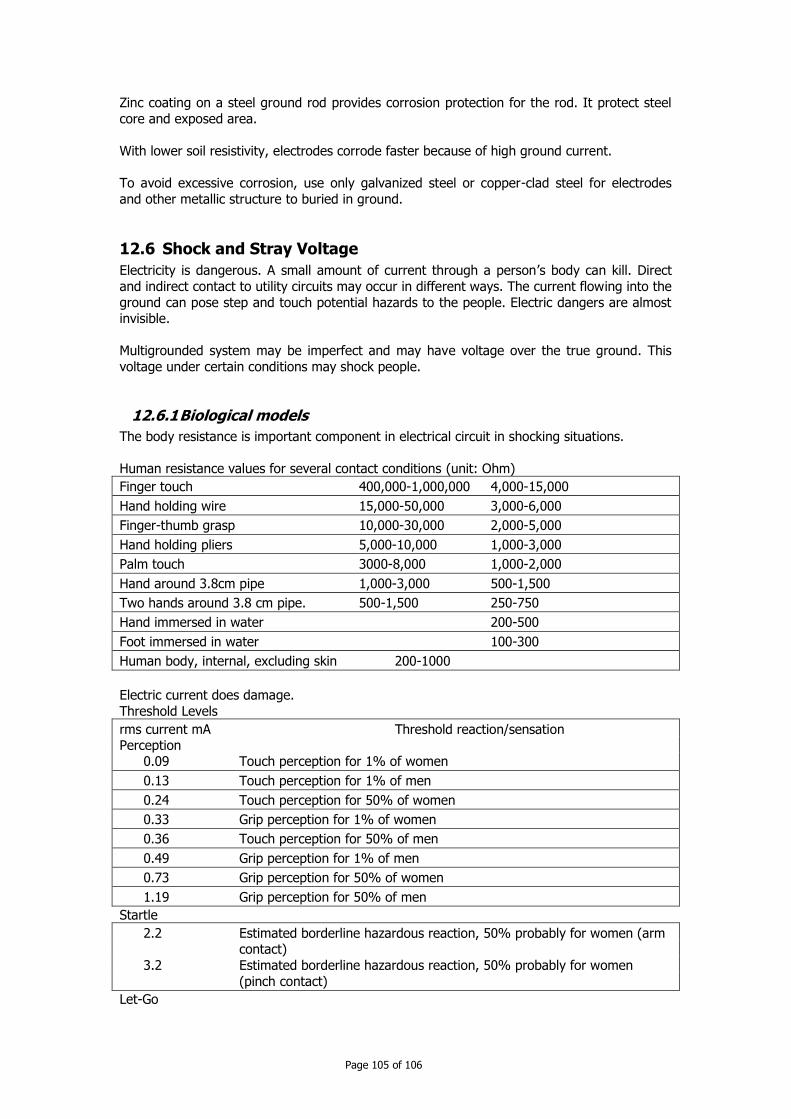
Page 105 of 106
Zinc coating on a steel ground rod provides corrosion protection for the rod. It protect steel
core and exposed area.
With lower soil resistivity, electrodes corrode faster because of high ground current.
To avoid excessive corrosion, use only galvanized steel or copper-clad steel for electrodes
and other metallic structure to buried in ground.
12.6 Shock and Stray Voltage
Electricity is dangerous. A small amount of current through a person’s body can kill. Direct
and indirect contact to utility circuits may occur in different ways. The current flowing into the
ground can pose step and touch potential hazards to the people. Electric dangers are almost invisible.
Multigrounded system may be imperfect and may have voltage over the true ground. This
voltage under certain conditions may shock people.
12.6.1 Biological models
The body resistance is important component in electrical circuit in shocking situations.
Human resistance values for several contact conditions (unit: Ohm)
Finger touch 400,000-1,000,000 4,000-15,000
Hand holding wire 15,000-50,000 3,000-6,000
Finger-thumb grasp 10,000-30,000 2,000-5,000
Hand holding pliers 5,000-10,000 1,000-3,000
Palm touch 3000-8,000 1,000-2,000
Hand around 3.8cm pipe 1,000-3,000 500-1,500
Two hands around 3.8 cm pipe. 500-1,500 250-750
Hand immersed in water 200-500
Foot immersed in water 100-300
Human body, internal, excluding skin 200-1000
Electric current does damage.
Threshold Levels
rms current mA Threshold reaction/sensation Perception
0.09 Touch perception for 1% of women
0.13 Touch perception for 1% of men
0.24 Touch perception for 50% of women
0.33 Grip perception for 1% of women
0.36 Touch perception for 50% of men
0.49 Grip perception for 1% of men
0.73 Grip perception for 50% of women
1.19 Grip perception for 50% of men
Startle
2.2 Estimated borderline hazardous reaction, 50% probably for women (arm contact)
3.2 Estimated borderline hazardous reaction, 50% probably for women
(pinch contact)
Let-Go

Page 106 of 106
4.5 Estimated let-go for 0.5% of children
6.0 Let-go for 0.5% of women
9.0 Let-go for 0.5% of men
10.5 Let-go for 50% of women
16.0 Let-go for 50% of men
Respiratory Tetanus
15 Breathing difficulty for 50% of women
23 Breathing difficulty for 50% of men
Fibrillation
35 Estimated 3s fibrillation current for children
100 Estimated 3s fibrillation current for adults
12.6.2 Step and touch potentials
During ground faults, all the ground current returns to the substation’s transformer. This current creates a significant voltage gradient along the ground and at between the ground
and conducting objects.
A touch potential is considered a hand-to-foot or hand-to-hand contact.
A step potential creates a path through the legs from one foot to another.
For a step potential, the body current is Ibody = V step / (R body + 6 rho) Where rho = soil resistivity (ohm-m), 6 rho = approximated twice earth-foot resistance
For a touch potential, the body current I body = V touch / (R body + 1.5 rho)
12.6.3 Stray voltage
Stray voltage is a touch voltage that end-users experience. Many of stray voltage problems are due to improper facility grounding and bonding. Many stray voltage problems originate on
the secondary system. Regardless of the origin of the stray voltage, localized bonding can
eliminate touch potentials.
Utility side solution to stray voltage includes: Balancing load among the phases (This can reduce he earth-return current)
Single-phase lines should be converted to two or three phase. This helps reduce the neutral-to-earth current.
Upgrading neutral size provides a lower-impedance path for earth-return current.
Check capacitor banks for blown fuses because of the blown fuse the unbalance can create excessive neutral current.
12.6.4 Tree contacts
Trees cause possibly dangerous shocking hazard. A tree in contact with an energized phase
conductor may create touch potential hazard near the ground.
The body current for a touch potential to a tree involves resistance of tree, the tree's resistance to ground in the earth, the conductor voltage, person's hand and foot contact
resistance. To reduce possible tree-related shock should be reduced by:
Educating the public on the dangers of cutting trees in the vicinity of power lines. trimming trees away from power lines
training tree-trimming crews Using covered wire instead of bare wire.