For Precision Control Speed Reducer CSF-3 Series Manual
27
For Precision Control HarmonicDrive ® Speed Reducer CSF-3 Series Manual ● Thank you very much for your purchasing our HarmonicDrive CSF-3 series. ● Be sure to use sufficient safety measures when installing and operating the equipment so as to prevent an accident resulting in a serious physical injury damaged by a malfunction or improper operation. ● Product specifications are subject to change without notice for improvement purposes. ● Keep this manual in a convenient location and refer to it whenever necessary in operating or maintaining the units. ● The end user of the driver should have a copy of this manual. ISO14001 (HOTAKA Plant) ISO9001
Transcript of For Precision Control Speed Reducer CSF-3 Series Manual
For Precision Control HarmonicDrive® Speed Reducer
CSF-3 Series Manual
● Thank you very much for your purchasing our HarmonicDrive CSF-3 series.
● Be sure to use sufficient safety measures when installing and operating the equipment so as to prevent an accident resulting in a serious physical injury damaged by a malfunction or improper operation.
● Product specifications are subject to change without notice for improvement purposes.
● Keep this manual in a convenient location and refer to it whenever necessary in operating or maintaining the units.
● The end user of the driver should have a copy of this manual.
ISO14001(HOTAKA Plant)ISO9001
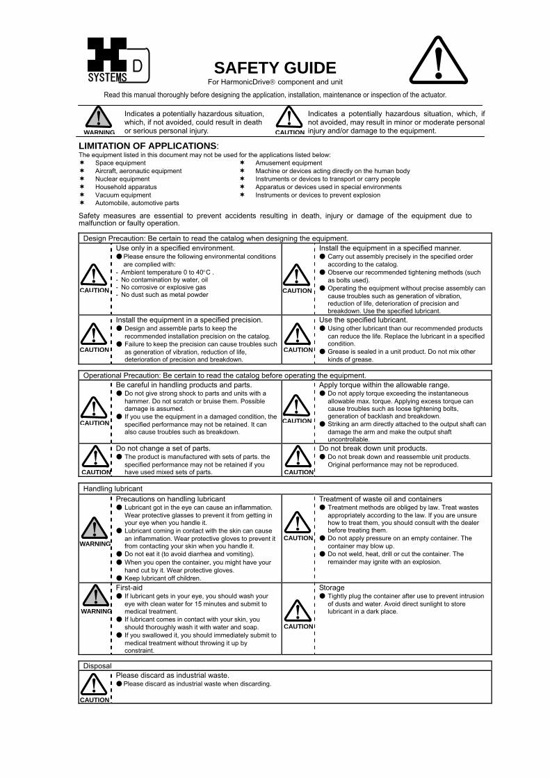
SAFETY GUIDE
For HarmonicDrive® component and unit
Read this manual thoroughly before designing the application, installation, maintenance or inspection of the actuator.
SYSTEMS
Indicates a potentially hazardous situation, which, if not avoided, could result in death or serious personal injury.
Indicates a potentially hazardous situation, which, if not avoided, may result in minor or moderate personal injury and/or damage to the equipment. WARNING CAUTION
LIMITATION OF APPLICATIONS: The equipment listed in this document may not be used for the applications listed below:
Space equipment Amusement equipment Aircraft, aeronautic equipment Machine or devices acting directly on the human body Nuclear equipment Instruments or devices to transport or carry people Household apparatus Apparatus or devices used in special environments Vacuum equipment Instruments or devices to prevent explosion Automobile, automotive parts
Safety measures are essential to prevent accidents resulting in death, injury or damage of the equipment due to
lfunction or faulty operation. ma
Design Precaution: Be certain to read the catalog when designing the equipment. Use only in a specified environment.
● Please ensure the following environmental conditions are complied with:
- Ambient temperature 0 to 40°C . - No contamination by water, oil - No corrosive or explosive gas - No dust such as metal powder
Install the equipment in a specified manner. ● Carry out assembly precisely in the specified order
according to the catalog. ● Observe our recommended tightening methods (such
as bolts used). ● Operating the equipment without precise assembly can
cause troubles such as generation of vibration, reduction of life, deterioration of precision and breakdown. Use the specified lubricant.
Install the equipment in a specified precision. ● Design and assemble parts to keep the
recommended installation precision on the catalog. ● Failure to keep the precision can cause troubles such
as generation of vibration, reduction of life, deterioration of precision and breakdown.
Use the specified lubricant. ● Using other lubricant than our recommended products
can reduce the life. Replace the lubricant in a specified condition.
● Grease is sealed in a unit product. Do not mix other kinds of grease.
Operational Precaution: Be certain to read the catalog before operating the equipment. Be careful in handling products and parts.
● Do not give strong shock to parts and units with a hammer. Do not scratch or bruise them. Possible damage is assumed.
● If you use the equipment in a damaged condition, the specified performance may not be retained. It can also cause troubles such as breakdown.
Apply torque within the allowable range. ● Do not apply torque exceeding the instantaneous
allowable max. torque. Applying excess torque can cause troubles such as loose tightening bolts, generation of backlash and breakdown.
● Striking an arm directly attached to the output shaft can damage the arm and make the output shaft uncontrollable.
Do not change a set of parts. ● The product is manufactured with sets of parts. the
specified performance may not be retained if you have used mixed sets of parts.
Do not break down unit products. ● Do not break down and reassemble unit products.
Original performance may not be reproduced.
Handling lubricant Precautions on handling lubricant
● Lubricant got in the eye can cause an inflammation. Wear protective glasses to prevent it from getting in your eye when you handle it.
● Lubricant coming in contact with the skin can cause an inflammation. Wear protective gloves to prevent it from contacting your skin when you handle it.
● Do not eat it (to avoid diarrhea and vomiting). ● When you open the container, you might have your
hand cut by it. Wear protective gloves. ● Keep lubricant off children.
Treatment of waste oil and containers ● Treatment methods are obliged by law. Treat wastes
appropriately according to the law. If you are unsure how to treat them, you should consult with the dealer before treating them.
● Do not apply pressure on an empty container. The container may blow up.
● Do not weld, heat, drill or cut the container. The remainder may ignite with an explosion.
First-aid ● If lubricant gets in your eye, you should wash your
eye with clean water for 15 minutes and submit to medical treatment.
● If lubricant comes in contact with your skin, you should thoroughly wash it with water and soap.
● If you swallowed it, you should immediately submit to medical treatment without throwing it up by constraint.
Storage ● Tightly plug the container after use to prevent intrusion
of dusts and water. Avoid direct sunlight to store lubricant in a dark place.
Disposal Please discard as industrial waste.
● Please discard as industrial waste when discarding.
CAUTION CAUTION
CAUTION CAUTION
CAUTIONCAUTION
WARNING
WARNING
CAUTION
CAUTION
CAUTION CAUTION
CAUTION
CSF-3 series manual
- Contents 1 -
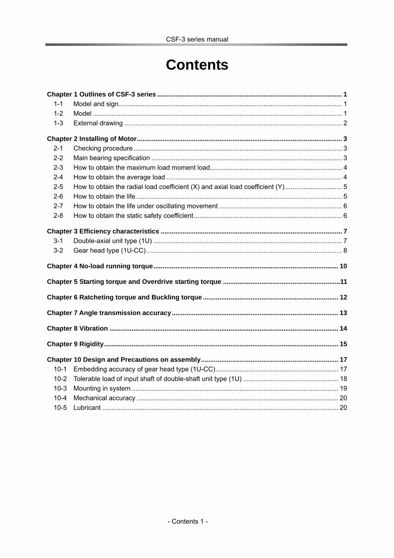
Contents
Chapter 1 Outlines of CSF-3 series ..................................................................................................... 1 1-1 Model and sign.......................................................................................................................... 1 1-2 Model ........................................................................................................................................ 1 1-3 External drawing ....................................................................................................................... 2
Chapter 2 Installing of Motor................................................................................................................ 3 2-1 Checking procedure.................................................................................................................. 3 2-2 Main bearing specification ........................................................................................................ 3 2-3 How to obtain the maximum load moment load........................................................................ 4 2-4 How to obtain the average load ................................................................................................ 4 2-5 How to obtain the radial load coefficient (X) and axial load coefficient (Y) ............................... 5 2-6 How to obtain the life................................................................................................................. 5 2-7 How to obtain the life under oscillating movement ................................................................... 6 2-8 How to obtain the static safety coefficient................................................................................. 6
Chapter 3 Efficiency characteristics ................................................................................................... 7 3-1 Double-axial unit type (1U) ....................................................................................................... 7 3-2 Gear head type (1U-CC)........................................................................................................... 8
Chapter 4 No-load running torque..................................................................................................... 10
Chapter 5 Starting torque and Overdrive starting torque ................................................................11
Chapter 6 Ratcheting torque and Buckling torque .......................................................................... 12
Chapter 7 Angle transmission accuracy........................................................................................... 13
Chapter 8 Vibration ............................................................................................................................. 14
Chapter 9 Rigidity................................................................................................................................ 15
Chapter 10 Design and Precautions on assembly........................................................................... 17 10-1 Embedding accuracy of gear head type (1U-CC)................................................................... 17 10-2 Tolerable load of input shaft of double-shaft unit type (1U) .................................................... 18 10-3 Mounting in system ................................................................................................................. 19 10-4 Mechanical accuracy .............................................................................................................. 20 10-5 Lubricant ................................................................................................................................. 20

CSF-3 series manual
- Contents 2 -
Memo
Chapter 1 Outlines of CSF-3 series
- 1 -
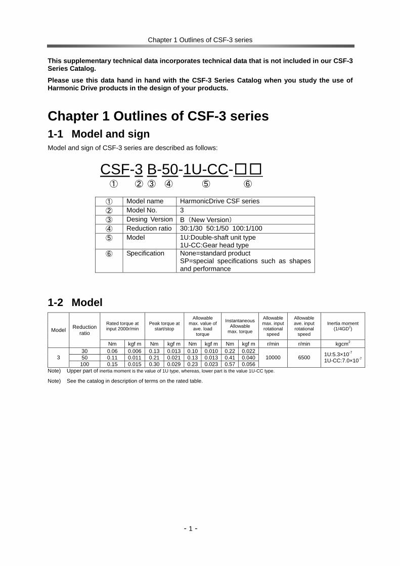
This supplementary technical data incorporates technical data that is not included in our CSF-3 Series Catalog.
Please use this data hand in hand with the CSF-3 Series Catalog when you study the use of Harmonic Drive products in the design of your products.
Chapter 1 Outlines of CSF-3 series 1-1 Model and sign Model and sign of CSF-3 series are described as follows:
CSF-3 B-50-1U-CC-□□ ① ② ③ ④ ⑤ ⑥
① Model name HarmonicDrive CSF series ② Model No. 3 ③ Desing Version B(New Version) ④ Reduction ratio 30:1/30 50:1/50 100:1/100 ⑤ Model 1U:Double-shaft unit type
1U-CC:Gear head type ⑥ Specification None=standard product
SP=special specifications such as shapes and performance
1-2 Model Rated torque at input 2000r/min
Peak torque at start/stop
Allowable max. value of
ave. load torque
Instantaneous Allowable
max. torque
Allowable max. input rotational
speed
Allowable ave. input rotational
speed
Inertia moment (1/4GD2) Model Reduction
ratio
Nm kgf m Nm kgf m Nm kgf m Nm kgf m r/min r/min kgcm2 30 0.06 0.006 0.13 0.013 0.10 0.010 0.22 0.02250 0.11 0.011 0.21 0.021 0.13 0.013 0.41 0.0403
100 0.15 0.015 0.30 0.029 0.23 0.023 0.57 0.05610000 6500 1U:5.3×10⁻⁷
1U-CC:7.0×10⁻⁷
Note) Upper part of inertia moment is the value of 1U type, whereas, lower part is the value 1U-CC type.
Note) See the catalog in description of terms on the rated table.
Chapter 1 Outlines of CSF-3 series
- 2 -
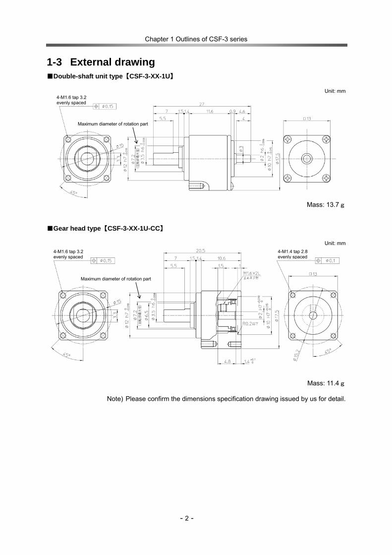
1-3 External drawing ■Double-shaft unit type【CSF-3-XX-1U】
Unit: mm
Mass: 13.7g ■Gear head type【CSF-3-XX-1U-CC】
Unit: mm
Mass: 11.4g
Note) Please confirm the dimensions specification drawing issued by us for detail.
4-M1.6 tap 3.2 evenly spaced
4-M1.6 tap 3.2 evenly spaced
Maximum diameter of rotation part
Maximum diameter of rotation part
4-M1.4 tap 2.8 evenly spaced
Chapter 2 Installing of Motor
3
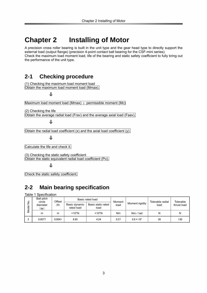
Chapter 2 Installing of Motor A precision cross roller bearing is built in the unit type and the gear head type to directly support the external load (output flange) (precision 4-point contact ball bearing for the CSF-mini series). Check the maximum load moment load, life of the bearing and static safety coefficient to fully bring out the performance of the unit type.
2-1 Checking procedure (1) Checking the maximum load moment load Obtain the maximum load moment load (Mmax).
⇓
Maximum load moment load (Mmax) ≤ permissible moment (Mc) (2) Checking the life Obtain the average radial load (Frav) and the average axial load (Faav).
⇓
Obtain the radial load coefficient (x) and the axial load coefficient (y). ⇓
Calculate the life and check it. (3) Checking the static safety coefficient Obtain the static equivalent radial load coefficient (Po).
⇓
Check the static safety coefficient.
2-2 Main bearing specification Table 1 Specification
Basic rated load Ball pitch circle
diameter (dp)
Offset(R) Basic dynamic
rated load Basic static rated
load
Moment load
Moment rigidity Tolerable radial load
Tolerable thrust load
Mod
el N
o.
m m ×102N ×102N Nm Nm/rad N N
3 0.0077 0.0041 6.65 4.24 0.27 0.9×10² 36 130
Chapter 2 Installing of Motor
4
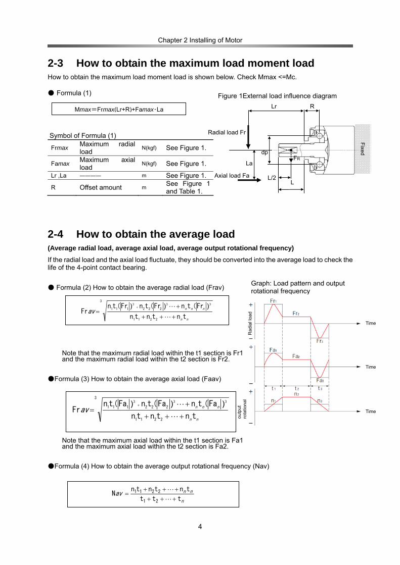
2-3 How to obtain the maximum load moment load How to obtain the maximum load moment load is shown below. Check Mmax <=Mc. ● Formula (1)
Symbol of Formula (1)
Frmax Maximum radial load
N(kgf) See Figure 1.
Famax Maximum axial load
N(kgf) See Figure 1.
Lr ,La ―――― m See Figure 1.
R Offset amount m See Figure 1 and Table 1.
2-4 How to obtain the average load (Average radial load, average axial load, average output rotational frequency) If the radial load and the axial load fluctuate, they should be converted into the average load to check the life of the 4-point contact bearing.
● Formula (2) How to obtain the average radial load (Frav)
Note that the maximum radial load within the t1 section is Fr1 and the maximum radial load within the t2 section is Fr2.
●Formula (3) How to obtain the average axial load (Faav)
Note that the maximum axial load within the t1 section is Fa1 and the maximum axial load within the t2 section is Fa2.
●Formula (4) How to obtain the average output rotational frequency (Nav)
Mmax=Frmax(Lr+R)+Famax・La
Figure 1External load influence diagram
nn
nnnav
tntntn
Fr(tnFr(tnFr(tnFr
2211
222111
3
+++
+=
+
L
L 333 )))
nn
nnnavtntntn
Fa(tnFa(tnFa(tnFr
2211
222111
3
+++
+=
+
L
L 333 )))
n
nnavttt
tntntnN
21
2211
++++++
=L
L
Axi
al lo
ad
outp
ut
rota
tiona
l fre
quen
cy
Graph: Load pattern and output rotational frequency
Rad
ial l
oad
Time
Time
Time
Fixed
Lr R
L L/2
FR La
dp
Radial load Fr
Axial load Fa
Chapter 2 Installing of Motor
5
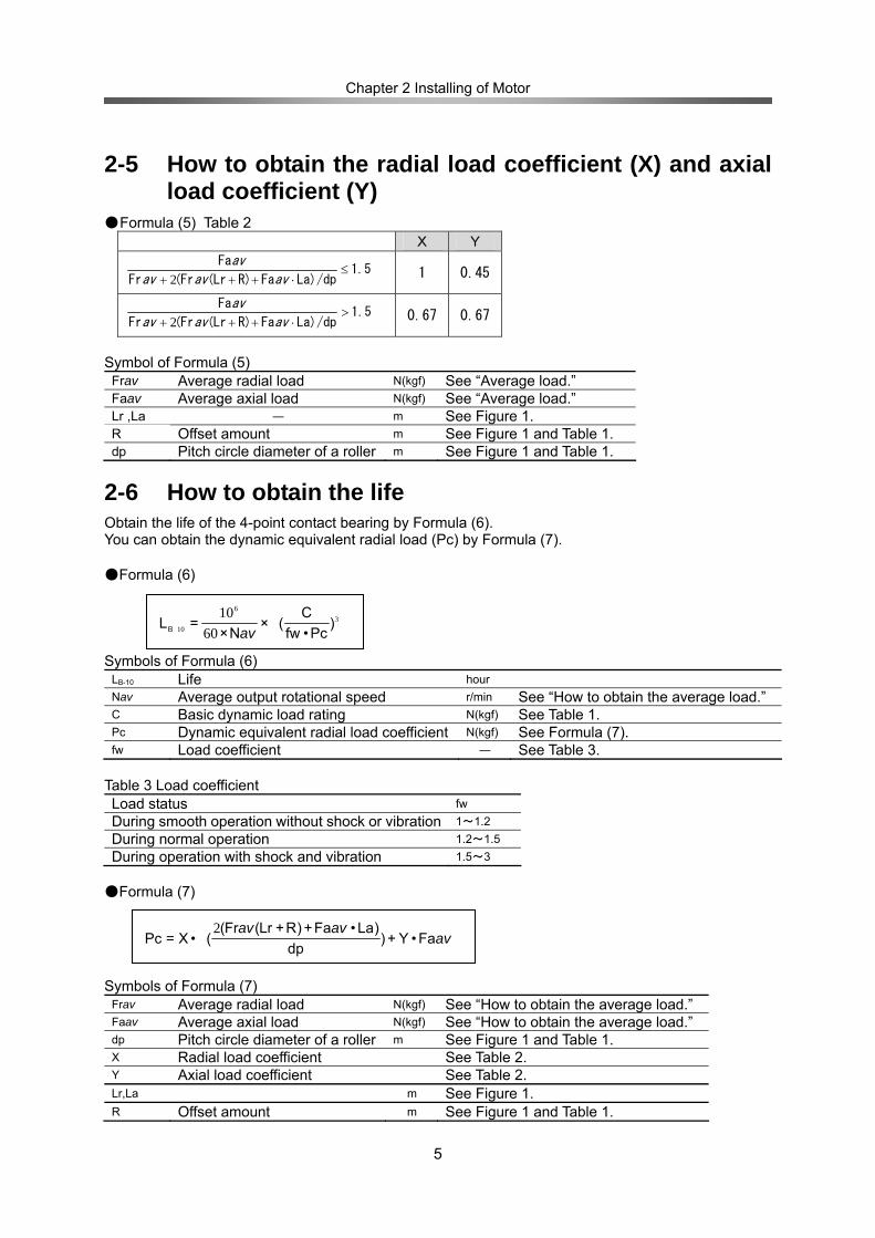
2-5 How to obtain the radial load coefficient (X) and axial load coefficient (Y)
● Formula (5) Table 2 X Y
1.5La)/dpFaR)(Lr(FrFr
Fa≤
⋅+++ avavav
av
2 1 0.45
1.5La)/dpFaR)(Lr(FrFr
Fa>
⋅+++ avavav
av
2 0.67 0.67
Symbol of Formula (5) Frav Average radial load N(kgf) See “Average load.” Faav Average axial load N(kgf) See “Average load.” Lr ,La ― m See Figure 1. R Offset amount m See Figure 1 and Table 1. dp Pitch circle diameter of a roller m See Figure 1 and Table 1.
2-6 How to obtain the life Obtain the life of the 4-point contact bearing by Formula (6). You can obtain the dynamic equivalent radial load (Pc) by Formula (7). ●Formula (6)
Symbols of Formula (6) LB-10 Life hour Nav Average output rotational speed r/min See “How to obtain the average load.” C Basic dynamic load rating N(kgf) See Table 1. Pc Dynamic equivalent radial load coefficient N(kgf) See Formula (7). fw Load coefficient ― See Table 3.
Table 3 Load coefficient Load status fw During smooth operation without shock or vibration 1~1.2 During normal operation 1.2~1.5 During operation with shock and vibration 1.5~3
●Formula (7)
Symbols of Formula (7) Frav Average radial load N(kgf) See “How to obtain the average load.” Faav Average axial load N(kgf) See “How to obtain the average load.” dp Pitch circle diameter of a roller m See Figure 1 and Table 1. X Radial load coefficient See Table 2. Y Axial load coefficient See Table 2. Lr,La m See Figure 1. R Offset amount m See Figure 1 and Table 1.
)Pc•fw
C(×
N×=LB
36
10 6010
av
Fa•Y+)dp
)La•Fa+)R+Lr(Fr((•X=Pc av
avav2
Chapter 2 Installing of Motor
6
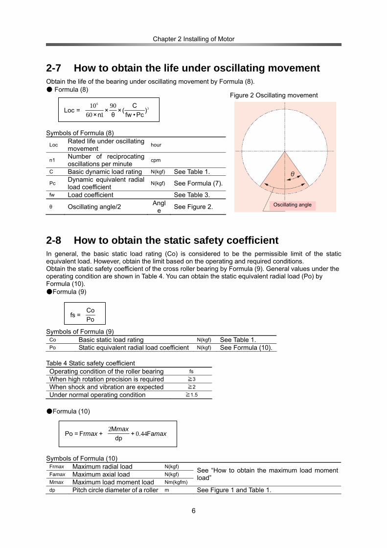
2-7 How to obtain the life under oscillating movement Obtain the life of the bearing under oscillating movement by Formula (8). ● Formula (8)
Symbols of Formula (8)
Loc Rated life under oscillating movement hour
n1 Number of reciprocating oscillations per minute
cpm
C Basic dynamic load rating N(kgf) See Table 1.
Pc Dynamic equivalent radial load coefficient N(kgf) See Formula (7).
fw Load coefficient See Table 3.
θ Oscillating angle/2 Angl
e See Figure 2.
2-8 How to obtain the static safety coefficient In general, the basic static load rating (Co) is considered to be the permissible limit of the static equivalent load. However, obtain the limit based on the operating and required conditions. Obtain the static safety coefficient of the cross roller bearing by Formula (9). General values under the operating condition are shown in Table 4. You can obtain the static equivalent radial load (Po) by Formula (10). ●Formula (9)
Symbols of Formula (9)
Co Basic static load rating N(kgf) See Table 1. Po Static equivalent radial load coefficient N(kgf) See Formula (10).
Table 4 Static safety coefficient Operating condition of the roller bearing fs When high rotation precision is required ≧3 When shock and vibration are expected ≧2 Under normal operating condition ≧1.5
●Formula (10) Symbols of Formula (10)
Frmax Maximum radial load N(kgf) Famax Maximum axial load N(kgf) Mmax Maximum load moment load Nm(kgfm)
See “How to obtain the maximum load moment load”
dp Pitch circle diameter of a roller m See Figure 1 and Table 1.
)Pc•fw
C(×
θ×
n×=Loc 3
6 90160
10
PoCo
=fs
Fa.+dp
M+Fr=Po max
maxmax 440
2
Figure 2 Oscillating movement
Oscillating angle
Chapter 3 Efficiency characteristics
- 7 -
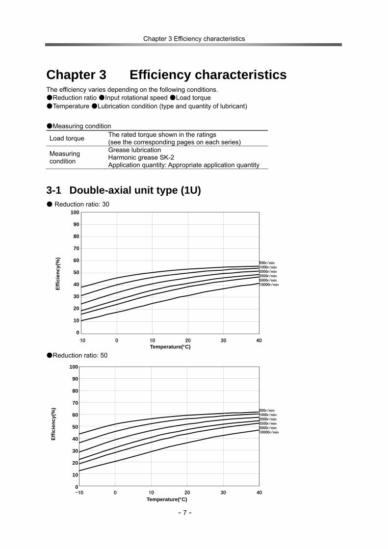
Chapter 3 Efficiency characteristics The efficiency varies depending on the following conditions. ●Reduction ratio ●Input rotational speed ●Load torque ●Temperature ●Lubrication condition (type and quantity of lubricant)
●Measuring condition
Load torque The rated torque shown in the ratings (see the corresponding pages on each series)
Measuring condition
Grease lubrication Harmonic grease SK-2 Application quantity: Appropriate application quantity
3-1 Double-axial unit type (1U) ● Reduction ratio: 30 ●Reduction ratio: 50
0%
10%
20%
30%
40%
50%
60%
70%
80%
90%
100%
-10 0 10 20 30 40
温度 (℃)
効率
(%) 500r/min
1000r/min2000r/min3500r/min5000r/min10000r/min
0%
10%
20%
30%
40%
50%
60%
70%
80%
90%
100%
-10 0 10 20 30 40
温度 (℃)
効率
(%)
500r/min1000r/min2000r/min3500r/min5000r/min10000r/min
100
90
80
70
60
50
40
30
20
10
0
100
90
80
70
60
50
40
30
20
10
0
Effic
ienc
y(%
) Ef
ficie
ncy(
%)
Temperature(°C)
Temperature(°C)
Chapter 3 Efficiency characteristics
- 8 -
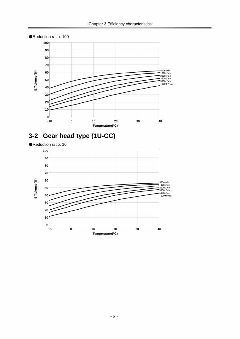
●Reduction ratio: 100
3-2 Gear head type (1U-CC) ●Reduction ratio: 30
0%
10%
20%
30%
40%
50%
60%
70%
80%
90%
100%
-10 0 10 20 30 40
温度 (℃)
効率
(%)
500r/min1000r/min2000r/min3500r/min5000r/min10000r/min
0%
10%
20%
30%
40%
50%
60%
70%
80%
90%
100%
-10 0 10 20 30 40
温度 (℃)
効率
(%) 500r/min
1000r/min2000r/min3500r/min5000r/min10000r/min
100
90
80
70
60
50
40
30
20
10
0
100
90
80
70
60
50
40
30
20
10
0
Effic
ienc
y(%
)
Temperature(°C)
Effic
ienc
y(%
)
Temperature(°C)
Chapter 3 Efficiency characteristics
- 9 -
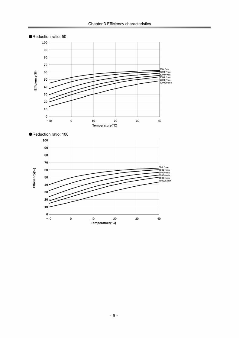
●Reduction ratio: 50 ●Reduction ratio: 100
0%
10%
20%
30%
40%
50%
60%
70%
80%
90%
100%
-10 0 10 20 30 40
温度 (℃)
効率
(%)
500r/min1000r/min2000r/min3500r/min5000r/min10000r/min
0%
10%
20%
30%
40%
50%
60%
70%
80%
90%
100%
-10 0 10 20 30 40
温度 (℃)
効率
(%)
500r/min1000r/min2000r/min3500r/min5000r/min10000r/min
100
90
80
70
60
50
40
30
20
10
0
100
90
80
70
60
50
40
30
20
10
0
Effic
ienc
y(%
)
Temperature(°C)
Effic
ienc
y(%
)
Temperature(°C)

Chapter 4 No-load running torque
- 10 -
Chapter 4 No-load running torque No-load running torque means the torque required to put CSF-3 under a no-load condition. * Please contact your Harmonic Drive sales representative for more details.
●Measuring condition Model: CSF-3-100-1U-CC (Gear Head Type)
Reduction ratio: 100 Measuring condition: Grease lubrication (Harmonic grease SK-2) The torque value is the value after a trial run of at two hours at an input of 2000 r/min.
●Correction amount by reduction ratio No-load running torques of Harmonic Drive vary in accordance with the reduction ratio. The values in Graph 1 below are the values for the gear head type (1U-CC, reduction ratio 1/100). Other reduction ratios can be calculated by adding correction amounts shown in Table 1. Table 1 Unit: cNm
Double-axial unit type (1U)
Gear head type (1U-CC)
Reduction ratio 30 50 100 30 50 Correction
amount 0.026 0.023 0.006 0.020 0.017
Graph 1 No-load running torque of gear head type (1U-CC, reduction ratio 1/100)
0.01
0.10
1.00
-10 0 10 20 30 40
温度 (℃)
無負
荷ランニングトル
ク(cNm)
10000r/min
5000r/min 3500r/min 2000r/min 1000r/min 500r/min
Temperature °C
No-
load
runn
ing
torq
ue c
Nm
Chapter 5 Starting torque and Overdrive starting torque
- 11 -
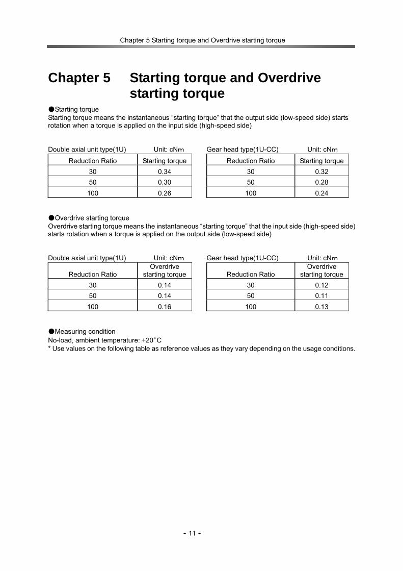
Chapter 5 Starting torque and Overdrive starting torque
●Starting torque Starting torque means the instantaneous “starting torque” that the output side (low-speed side) starts rotation when a torque is applied on the input side (high-speed side) Double axial unit type(1U) Unit: cNm Gear head type(1U-CC) Unit: cNm
Reduction Ratio Starting torque Reduction Ratio Starting torque30 0.34 30 0.32 50 0.30 50 0.28
100 0.26 100 0.24 ●Overdrive starting torque Overdrive starting torque means the instantaneous “starting torque” that the input side (high-speed side) starts rotation when a torque is applied on the output side (low-speed side) Double axial unit type(1U) Unit: cNm Gear head type(1U-CC) Unit: cNm
Reduction Ratio Overdrive
starting torque Reduction Ratio Overdrive
starting torque30 0.14 30 0.12 50 0.14 50 0.11
100 0.16 100 0.13 ●Measuring condition No-load, ambient temperature: +20ºC * Use values on the following table as reference values as they vary depending on the usage conditions.
Chapter 6 Starting torque and Overdrive starting torque
- 12 -
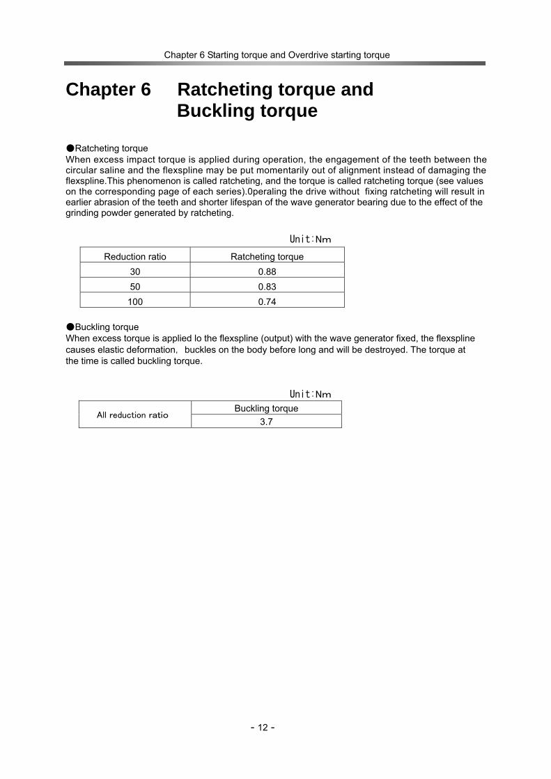
Chapter 6 Ratcheting torque and Buckling torque
●Ratcheting torque When excess impact torque is applied during operation, the engagement of the teeth between thecircular saline and the flexspline may be put momentarily out of alignment instead of damaging theflexspline.This phenomenon is called ratcheting, and the torque is called ratcheting torque (see valueson the corresponding page of each series).0peraling the drive without fixing ratcheting will result inearlier abrasion of the teeth and shorter lifespan of the wave generator bearing due to the effect of thegrinding powder generated by ratcheting.
Unit:Nm
●Buckling torque When excess torque is applied lo the flexspline (output) with the wave generator fixed, the flexspline causes elastic deformation,buckles on the body before long and will be destroyed. The torque at the time is called buckling torque.
Unit:Nm
Buckling torque All reduction ratio
3.7
Reduction ratio Ratcheting torque 30 0.88 50 0.83
100 0.74
Chapter 7 Angle transmission accuracy
- 13 -
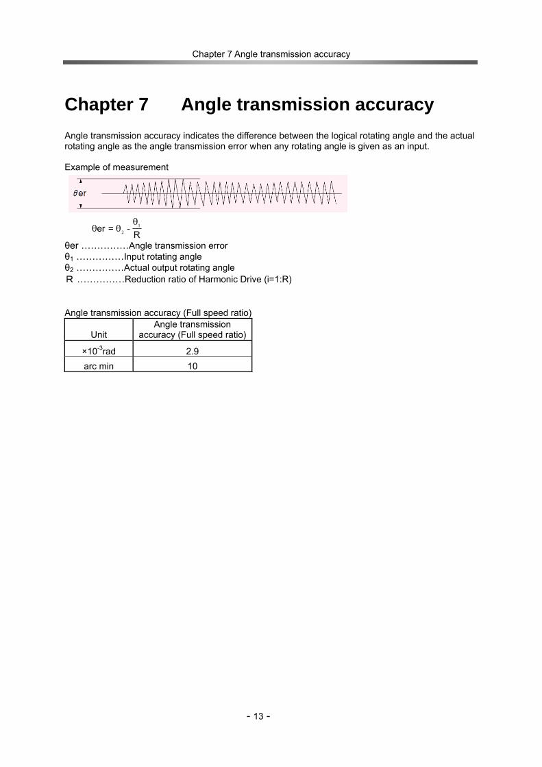
Chapter 7 Angle transmission accuracy Angle transmission accuracy indicates the difference between the logical rotating angle and the actual rotating angle as the angle transmission error when any rotating angle is given as an input. Example of measurement
R=er 1
2 -θ
θθ
θer ……………Angle transmission error θ1 ……………Input rotating angle θ2 ……………Actual output rotating angle R ……………Reduction ratio of Harmonic Drive (i=1:R) Angle transmission accuracy (Full speed ratio)
Unit Angle transmission
accuracy (Full speed ratio)
×10-3rad 2.9 arc min 10
Chapter 8 Vibration
14
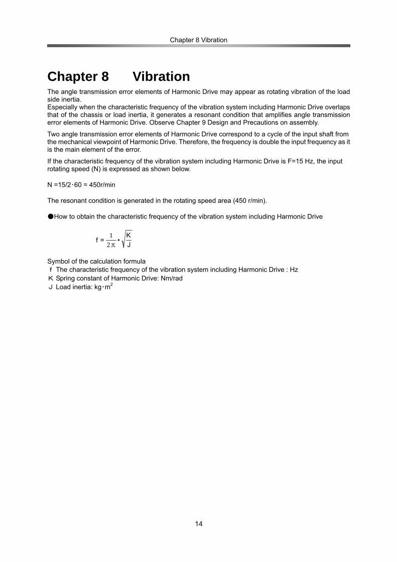
Chapter 8 Vibration The angle transmission error elements of Harmonic Drive may appear as rotating vibration of the load side inertia. Especially when the characteristic frequency of the vibration system including Harmonic Drive overlaps that of the chassis or load inertia, it generates a resonant condition that amplifies angle transmission error elements of Harmonic Drive. Observe Chapter 9 Design and Precautions on assembly.
Two angle transmission error elements of Harmonic Drive correspond to a cycle of the input shaft from the mechanical viewpoint of Harmonic Drive. Therefore, the frequency is double the input frequency as it is the main element of the error.
If the characteristic frequency of the vibration system including Harmonic Drive is F=15 Hz, the input rotating speed (N) is expressed as shown below. N =15/2・60 = 450r/min The resonant condition is generated in the rotating speed area (450 r/min). ●How to obtain the characteristic frequency of the vibration system including Harmonic Drive
JK
•=fπ21
Symbol of the calculation formula f The characteristic frequency of the vibration system including Harmonic Drive : Hz K Spring constant of Harmonic Drive: Nm/rad J Load inertia: kg・m2

Chapter 9 Rigidity
15
Chapter 9 Rigidity Rigidity and backlash of the drive system greatly affects the performance of the servo system. A detailed review of these items is required before designing the equipment and selecting a model number.
Rigidity Fixing the input side (wave generator) and applying torque to the output side (flexspline) generates torsion almost proportional to the torque on the output side. Figure O18-1 shows the torsional angle quantity on the output side when the torque applied on the output side starts from zero, increases up to +T0 and decreases down to –T0. This is called the “Torque – torsional angle diagram,” which normally draws a loop of 0-A-B-A’-B’-A. The slope described in the “Torque – torsional angle diagram” is represented as the spring constant for the rigidity of Harmonic Drive (unit: Nm/rad). As shown in Figure 020-2, this “Torque – torsional angle diagram” is divided into 3 partitions, and the spring constants in the area are represented as K1, K2 and K3. K1 – The spring constant when the torque changes from [zero] to [T1] K2 – The spring constant when the torque changes from [T1] to [T2] K3 – The spring constant when the torque changes from [T2] to [T3] Torsional angle can be calculated by the following formulas.
* φ: torsional angle
◆ Torque T is T1 or less:
◆ Torque T is between T1 and T2:
◆ Torque T is between T2 and T3:
The following table shows average values of T1 to T3, K1 to K3 and θ1 to θ2.
Spring constant Model
No. Sign Unit Reduction
ratio 30 Reduction
ratio 50 Reduction ratio 100
Nm 0.016 0.016 0.016 T1 kgf m 0.0016 0.0016 0.0016 Nm/rad 27 30 34 K1 ×10-4kgf m/arc min 8 9 10 ×10-4rad 5.9 5.3 4.7 θ1 arc min 2.0 1.8 1.6 Nm 0.05 0.05 0.05 T2 kgf m 0.005 0.005 0.005 Nm/rad 40 47 54 K2 ×10-4kgf m/arc min 12 14 16 ×10-4rad 12.5 10.6 9.3 θ2 arc min 4.2 3.6 3.1 Nm/rad 51 57 67
3
K3 ×10-4kgf m/arc min 15 17 20
3
22
KTT −
+θ=ϕ
2
11
KTT −
+θ=ϕ
1KT
=ϕ
Figure 1 ね
じり角
ヒステリシスロス
トルク0
B’
B
A
+T0-T0
A’
ねじり角 K3
K2
K1
T1 T2
トルク0θ1
θ2
Tors
iona
l ang
le
Tors
iona
l ang
le
Torque
Torque
Hysteresis loss

Chapter 8 Rigidity
16
Hysteresis loss As shown in Figure 020-1, when the torque is applied up to the rated value and is brought back to [zero], the torsional angle does not become absolutely [zero] and a small amount remains. This is called hysteresis loss. Hysteresis amount
Reduction ratio Unit Hysteresis amount
×10-4rad 1.3 30 arc min 4.5
×10-4rad 1.2 50 arc min 4
×10-4rad 1.2 100 arc min 4
Backlash CSF-3 wave generators are of the rigid type (solid type) and are backlash free.

Chapter 10 Design and Precautions on assembly
17
Chapter 10 Design and Precautions on assembly
10-1 Embedding accuracy of gear head type (1U-CC) Maintain the recommended case accuracy shown below in design for embedding to ensure that excellent performance of Harmonic Drive is fully demonstrated. Recommended accuracy for case embedding
Recommended tolerance for socket and spigot joint h6
Recommended allowance of the shaft h6 Wave generator mounting face
Case mating face

Chapter 10 Design and Precautions on assembly
18
10-2 Tolerable load of input shaft of double-shaft unit type (1U)
The input part of the double-shaft unit type is supported by two single row deep groove bearings. Check
the load applied to the input part to ensure that the performance of the double-shaft unit type is fully
demonstrated.
The following diagram illustrates the fulcrums of the bearings. Dimensions “a” and “b” are shown in the
following table. The following graph shows the relationship between the tolerable maximum radial load
and axial load of Model No. 3. The values in the graph are those when the average input rpm is
2,000r/min and basic rated life of L10 = 7,000h.
Example: The maximum tolerable radial load (Fr) will be 3.75N when an axial load (Fa) of 3N is applied to the input shaft.
Specification of bearings in input part Bearing A Bearing B
Model No. Basic dynamic
rated load Cr(N)
Basic static rated load
Cor(N)
Model No.
Basic dynamic rated load
Cr(N)
Basic static rated load
Cor(N)
Maximum radial load Fr(N)
MF63T12ZZ 242 94 681X 102 29 6 Bearing fulcrums Relationship between axial load (Fa) and tolerable maximum radial load (Fr)
0
2
4
6
8
10
0 1 2 3 4 5
アキシャル荷重Fa(N)
ラジアル
荷重
Fr(N)
Axial load Fa(N)
Rad
ial l
oad
Fr(N
)
Bearing A Bearing B
Fa: axial load(N) Fr: radial load(N)
Chapter 10 Design and Precautions on assembly
19
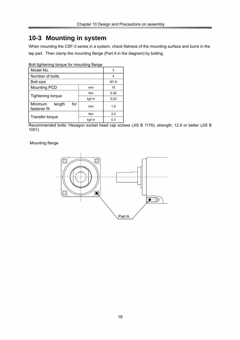
10-3 Mounting in system When mounting the CSF-3 series in a system, check flatness of the mounting surface and burrs in the
tap part. Then clamp the mounting flange (Part A in the diagram) by bolting.
Bolt tightening torque for mounting flange Model No. 3
Number of bolts 4
Bolt size M1.6
Mounting PCD mm 15
Nm 0.26 Tightening torque
kgf m 0.03
Minimum length for fastener fit mm 1.9
Nm 3.0 Transfer torque
kgf m 0.3
Recommended bolts: Hexagon socket head cap screws (JIS B 1176); strength, 12.9 or better (JIS B 1051) Mounting flange
Part A

Chapter 10 Design and Precautions on assembly
20
10-4 Mechanical accuracy Using ultra compact and high accuracy 4-point contact ball bearings as the main bearings, the CSF-3 series features a high accuracy of its output part. 10-5 Lubricant The standard lubricating method for the CSF-3 series is greasing of Harmonic Grease SK-2 developed specially for compact precision equipment. The CSF-3 series products are greased during preshipment inspection. No greasing or grease coating is needed when mounting them in systems. Grease specification Lubricant name Harmonic grease SK-2 Manufacturer Harmonic Drive Systems Ambient temperature rage 0℃ to +40℃ Base oil Refined oil Puffing agent Lithium soap base Additive Extreme-pressure additive, others NLGI consistency No. No.2 Consistency (25℃) 265 to 295 Drop point 198℃ Appearance Green Storage life 5 years in sealed condition
Concentricity of the mounting spigot Fluctuation on the edge of the output shaft
Fluctuation on the output flange face
Parallelism of the mounting face and the output flange face
Squareness of the mounting face

Chapter 10 Design and Precautions on assembly
21
Memo
Products that are described in this catalog are warranted as follows:
■ Warranty period Under the condition that the products are handled, used and maintained properly followed each item of the technical materials, the manuals, and this catalog, all the products are warranted against defects in workmanship and materials for the shorter period of either one year after delivery or 2,000 hours of operation time.
■ Warranty terms All the products are warranted against defects in workmanship and materials for the warranted period. This limited warranty does not apply to any product that has been subject to: (1)User's misapplication, improper installation, inadequate maintenance, or misuse. (2)Disassembling, modification or repair by others than Harmonic Drive Systems, Inc. (3)Imperfection caused by the other than the products. (4)Disaster or others that does not belong to the responsibility of Harmonic Drive Systems, Inc. Our liability shall be limited exclusively to repairing or replacing the product only found by Harmonic Drive Systems, Inc. to be defective. Harmonic Drive Systems, Inc. shall not be liable for consequential damages of other equipment caused by the defective products, and shall not be liable for the incidental and consequential expenses and the labor costs for detaching and installing to the driven equipment
Warranty Period and Terms
Head Office: Believe Omori 7F 6-25-3 Minami-Ohi,Shinagawa-ku,Tokyo,Japan 140-0013 TEL +81-(0)3-5471-7800 FAX +81-(0)3-5471-7811
Overseas Division: Believe Omori 7F, 6-25-3 Minami-Ohi, Shinagawa-ku,Tokyo, Japan 140-0013 TEL +81-(0)3-5471-7800 FAX: +81-(0)3-5471-7811
Hotaka Plant:1856-1 Maki, Hotaka, Azumino-shi, Nagano, Japan 399-8305 TEL +81-(0)263-83-6800 FAX +81-(0)263-83-6901
Harmonic Drive AG:Hoenbergstrasse 14 D-65555 Limburg a.d. Lahn Germany TEL +49-6431-5008-0 FAX +49-6431-5008-18
Harmonic Drive L.L.C:247 Lynnfield Street, Peabody, MA, 01960, U.S.A. TEL 978-532-1800 FAX 978-532-9406
№0710-2R-TCSF3-EHarmonicDrive is a registered trademark of Harmonic Drive Systems Inc.
Certified to ISO14001 (HOTAKA Plant) / ISO9001 (TÜV Management Service GmbH) All specifications and dimensions in this manual subject to change without notice.