FOR INNOVATE PART NUMBERS 6012 and 6013 Manual 1.0... · 6012 & 6013 innovate motorsports® scion...
49
6012 & 6013 INNOVATE MOTORSPORTS ® SCION FR-S / SUBARU BRZ / TOYOTA FT86 SUPERCHARGER KIT WITH INTERCOOLER FOR INNOVATE PART NUMBERS 6012 and 6013 INSTALLATION INSTRUCTIONS Kit Serial # ___________________________________________________ Supercharger Serial # _____________________________________________
Transcript of FOR INNOVATE PART NUMBERS 6012 and 6013 Manual 1.0... · 6012 & 6013 innovate motorsports® scion...
6012 & 6013
INNOVATE MOTORSPORTS® SCION FR-S / SUBARU BRZ / TOYOTA FT86
SUPERCHARGER KIT WITH INTERCOOLER
FOR INNOVATE PART NUMBERS
6012 and 6013
INSTALLATION INSTRUCTIONS
Kit Serial # ___________________________________________________
Supercharger Serial # _____________________________________________
FRS Manual 1.0 (intercooled).doc 2
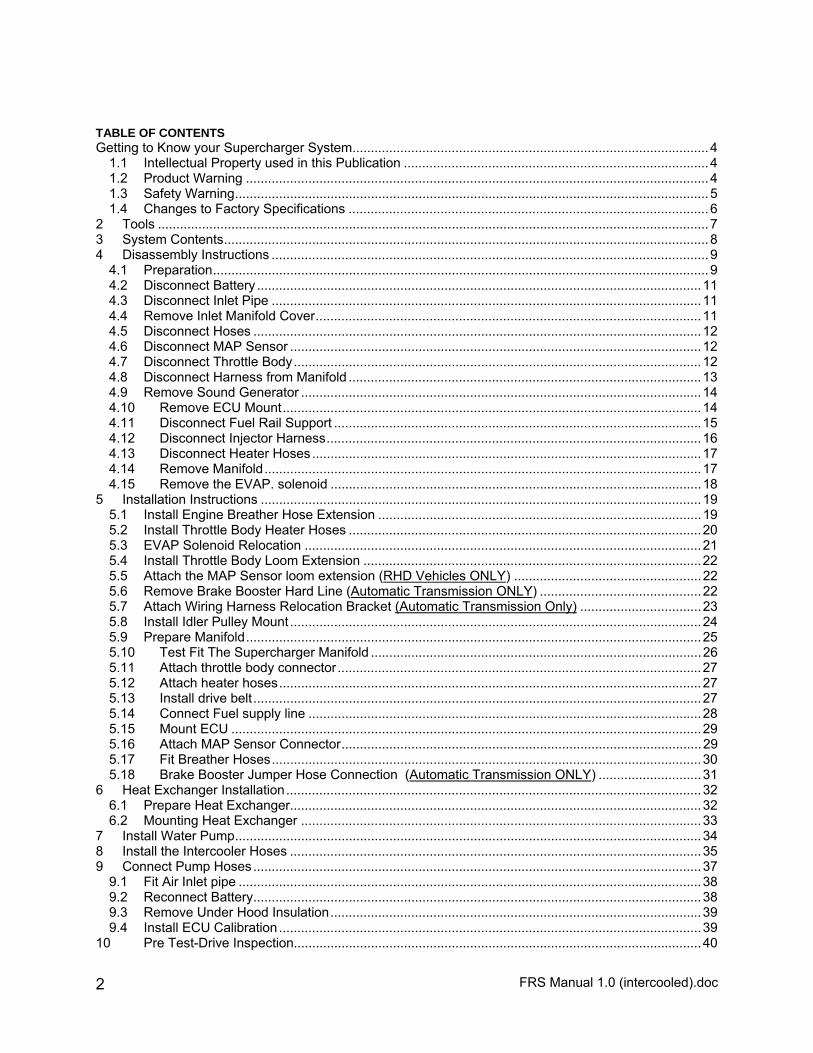
TABLE OF CONTENTS Getting to Know your Supercharger System.................................................................................................4
1.1 Intellectual Property used in this Publication ...................................................................................4 1.2 Product Warning ..............................................................................................................................4 1.3 Safety Warning.................................................................................................................................5 1.4 Changes to Factory Specifications ..................................................................................................6
2 Tools ......................................................................................................................................................7 3 System Contents....................................................................................................................................8 4 Disassembly Instructions .......................................................................................................................9
4.1 Preparation.......................................................................................................................................9 4.2 Disconnect Battery .........................................................................................................................11 4.3 Disconnect Inlet Pipe .....................................................................................................................11 4.4 Remove Inlet Manifold Cover.........................................................................................................11 4.5 Disconnect Hoses ..........................................................................................................................12 4.6 Disconnect MAP Sensor ................................................................................................................12 4.7 Disconnect Throttle Body...............................................................................................................12 4.8 Disconnect Harness from Manifold ................................................................................................13 4.9 Remove Sound Generator .............................................................................................................14 4.10 Remove ECU Mount..................................................................................................................14 4.11 Disconnect Fuel Rail Support ....................................................................................................15 4.12 Disconnect Injector Harness......................................................................................................16 4.13 Disconnect Heater Hoses..........................................................................................................17 4.14 Remove Manifold.......................................................................................................................17 4.15 Remove the EVAP. solenoid .....................................................................................................18
5 Installation Instructions ........................................................................................................................19 5.1 Install Engine Breather Hose Extension ........................................................................................19 5.2 Install Throttle Body Heater Hoses ................................................................................................20 5.3 EVAP Solenoid Relocation ............................................................................................................21 5.4 Install Throttle Body Loom Extension ............................................................................................22 5.5 Attach the MAP Sensor loom extension (RHD Vehicles ONLY) ...................................................22 5.6 Remove Brake Booster Hard Line (Automatic Transmission ONLY) ............................................22 5.7 Attach Wiring Harness Relocation Bracket (Automatic Transmission Only) .................................23 5.8 Install Idler Pulley Mount ................................................................................................................24 5.9 Prepare Manifold............................................................................................................................25 5.10 Test Fit The Supercharger Manifold ..........................................................................................26 5.11 Attach throttle body connector...................................................................................................27 5.12 Attach heater hoses...................................................................................................................27 5.13 Install drive belt ..........................................................................................................................27 5.14 Connect Fuel supply line ...........................................................................................................28 5.15 Mount ECU ................................................................................................................................29 5.16 Attach MAP Sensor Connector..................................................................................................29 5.17 Fit Breather Hoses.....................................................................................................................30 5.18 Brake Booster Jumper Hose Connection (Automatic Transmission ONLY) ............................31
6 Heat Exchanger Installation.................................................................................................................32 6.1 Prepare Heat Exchanger................................................................................................................32 6.2 Mounting Heat Exchanger .............................................................................................................33
7 Install Water Pump...............................................................................................................................34 8 Install the Intercooler Hoses ................................................................................................................35 9 Connect Pump Hoses..........................................................................................................................37
9.1 Fit Air Inlet pipe ..............................................................................................................................38 9.2 Reconnect Battery..........................................................................................................................38 9.3 Remove Under Hood Insulation.....................................................................................................39 9.4 Install ECU Calibration...................................................................................................................39
10 Pre Test-Drive Inspection...............................................................................................................40
FRS Manual 1.0 (intercooled).doc 3
10.1 Pre-Start Inspection ...................................................................................................................40 10.2 Engine Warm Up .......................................................................................................................40 10.3 Road Test Vehicle .....................................................................................................................40
11 Supercharger System Maintenance...............................................................................................41 11.1 Drive Belt ...................................................................................................................................41 11.2 Supercharger Gear Oil...............................................................................................................42
11.2.1 Check Oil Level .....................................................................................................................42 11.2.2 Replace Gear Oil ...................................................................................................................43
12 LIMITED WARRANTY ...................................................................................................................44 13 Revision History .............................................................................................................................47 SUPERCHARGER WARRANTY REGISTRATION FORM ........................................................................49
FRS Manual 1.0 (intercooled).doc 4
Getting to Know your Supercharger System
1.1 Intellectual Property used in this Publication This document is copyright of Innovate Motorsports. This document may not be re-sold, copied or distributed in any way without prior written authorization of a director of Innovate Motorsports. Innovate Motorsports has patents for its products or are pending. Any unauthorized copying or modification of the Innovate Motorsports products may result in legal action. Copyrights / Trademarks: Innovate Motorsports® is a registered trademark of Performance Motorsports, Inc. Innovate Motorsports has patents for its superchargers. Any unauthorized copying or modification of the system may result in legal action. Loctite® and Grey Maxx® are registered trademarks of Henkel KGaA, a company incorporated in Germany. Other than commercial supply arrangements, Henkel KGaA does not have any association with Innovate Motorsports. RedLine® is a registered trademark of RedLine Synthetic Oil Corporation, a company incorporated in the United States of America. Other than commercial supply arrangements, Redline and RedLine Synthetic Oil Corporation do not have any association with Innovate Motorsports. Toyota FT86, Subaru BRZ & Scion FR-S are registered trademarks of Toyota, Subaru & Scion Companies SAE is a trademark of SAE International (www.sae.org), a global technology information and standards setting resource organization for the design, manufacturing, operation, and maintenance industry. Gates is a registered trademark of the Gates Rubber Company, a subsidiary of Tomkins PLC, incorporated in London, United Kingdom. Other than commercial supply arrangements, Gates and Tomkins PLC do not have any association with Innovate Motorsports Limited.
1.2 Product Warning
Installation of the Innovate Motorsports Supercharger kit on Scion FR-S, Subaru BRZ & Toyota FT86 vehicles may void all or parts of Toyota, Subaru & Scion Warranties. Customers should consult their dealer for details. Innovate Motorsports makes no representation that installation and use of the Innovate Motorsports supercharger kit is legal for public road use worldwide. Customers should check that installation and use of the Innovate Motorsports supercharger kit on their vehicle is legal by contacting the relevant statutory authority in their jurisdiction prior to use on roads.
Innovate Motorsports supports safe driving. So always remember to observe all speed limits and road rules relevant to the state, city or other local jurisdiction.
Provided in this installation manual are detailed instructions to the installer on how to install the Innovate Motorsports patent pending supercharger kit to the Toyota FT86 / Subaru BRZ / Scion FR-S vehicle (the vehicle). The instructions are aimed at being simple yet informative, and are aided with well-presented
FRS Manual 1.0 (intercooled).doc 5
pictures to make installations as simple, fast, and problem free as possible. Please read the entire instruction manual prior to beginning the installation procedure. Pictures and descriptions may vary slightly from model to model. It is recommended that all wiring harness connectors, and vacuum hoses are labeled at the time of removal for easy and correct refitting. Some components that are removed and are to be refitted are fragile, and should be stored safely to prevent damage to these components. Innovate Motorsports recommends performing the following vehicle checks prior to installing the supercharger.
1) Check that the factory fuel system is operating correctly. 2) Inspect the factory exhaust catalyst for blocks or damage. 3) Check fuel quality in fuel tank ensuring that it is not stale or low octane fuel. Replace with a higher octane, 91 octane Premium Unleaded Gasoline as required. It is also recommended to replace the fuel filter if the vehicle has travelled more than 9000 miles or 15,000 Km.
Innovate Motorsports will not be liable for any loss, damage, payment, costs, expenses or other liability, not expressly stated in this document. In particular, Innovate Motorsports shall not be liable to any person for any consequential, indirect or economic loss or punitive or exemplary damages of any kind. Innovate Motorsports reserves the right to change specifications from time to time and will not be liable to any person for doing so. Innovate Motorsports believes that information in this document is correct at time of print. Innovate Motorsports limits its liability to the maximum extent permissible at law with regard to the reliance which any person places on anything in this document.
THIS INNOVATE MOTORSPORTS INSTALLATION REQUIRES THAT THE VEHICLE BE FITTED WITH AN APPROVED ECU AND ECU CALIBRATION. FAILURE TO ENSURE
THIS WILL CAUSE CATISTROPHIC ENGINE FAILURE AND VOID ALL WARRANTY.
1.3 Safety Warning No unauthorized service or alteration may be undertaken to the Innovate Motorsports supercharger. Installation should be carried out in a workshop which is a safe and ventilated working environment with equipment and procedures compliant with local authority guidelines and legal requirements. Installers should ensure adequate hearing, eye, and physical protection is used at all times during the installation process. Installers should take reasonable precautions to avoid fatigue and closely follow the installation instructions during every installation. Innovate Motorsports recommends installation should not be carried out unsupervised. Innovate Motorsports, its directors, employees and agents will not accept liability for damage accident or injury resulting from the installation process. Safety warnings are also provided throughout this document.
Many of the photos shown in this document are of a typical FT86 Right hand drive vehicle and are similar to a typical FT86 Left hand drive vehicle.

FRS Manual 1.0 (intercooled).doc 6
Some of the terminology and language used in this instruction may vary from that of the end user / installer’s expectations, as some tools and automotive components have different common names in different geographical locations.
1.4 Changes to Factory Specifications
FUEL: 91 OCTANE (OR HIGHER) PREMIUM UNLEADED PUMP GASOLINE TO BE USED AT
ALL TIMES. NEVER ALLOW THE ENGINE TO KNOCK OR DETONATE AS SERIOUS ENGINE
DAMAGE MAY OCCUR.
REQUIRED SERVICE: (SEE MAINTENANCE SECTION OF MANUAL)
1. INSPECT SUPERCHARGER DRIVE BELT AT EVERY ROUTINE SERVICE AND
REPLACE WHEN REQUIRED.
2. DRAIN AND REPLACE SUPERCHARGER OIL EVERY 30,000 miles or 50,000
km. USE REDLINE 75W90 NS GEAR OIL OR EQUIVALENT. IT IS CRITICAL
NOT TO OVERFILL SUPERCHARGER GEARBOX AS DAMAGE WILL OCCUR.
FILL WITH EXACTLY 5.31oz 157mil.
THE ENGINE SITS AT A REARWARD ANGLE. THIS PREVENTS ACCURATE
MEASUREMENT OF THE GEAR OIL WITH THE DIPSTICK AND PROPER
DRAINING. WHEN MEASRING OR REPLACING THE SUPERCHARGER OIL
LEVEL, ENSURE THE ENGINE IS LEVEL.
CHECK OIL LEVEL WITH THE DIPSTICK PROVIDED IN THE SUPERCHARGER
ASSEMBLY. TIGHTEN DIPSTICK FULLY BEFORE CHECKING THE OIL LEVEL.
FRS Manual 1.0 (intercooled).doc 7
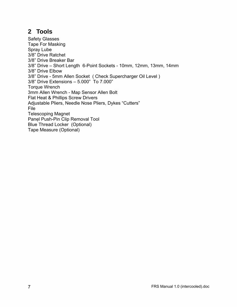
2 Tools Safety Glasses Tape For Masking Spray Lube 3/8” Drive Ratchet 3/8” Drive Breaker Bar 3/8” Drive – Short Length 6-Point Sockets - 10mm, 12mm, 13mm, 14mm 3/8” Drive Elbow 3/8” Drive - 5mm Allen Socket ( Check Supercharger Oil Level ) 3/8” Drive Extensions – 5.000” To 7.000” Torque Wrench 3mm Allen Wrench - Map Sensor Allen Bolt Flat Heat & Phillips Screw Drivers Adjustable Pliers, Needle Nose Pliers, Dykes “Cutters” File Telescoping Magnet Panel Push-Pin Clip Removal Tool Blue Thread Locker (Optional) Tape Measure (Optional)
FRS Manual 1.0 (intercooled).doc 8
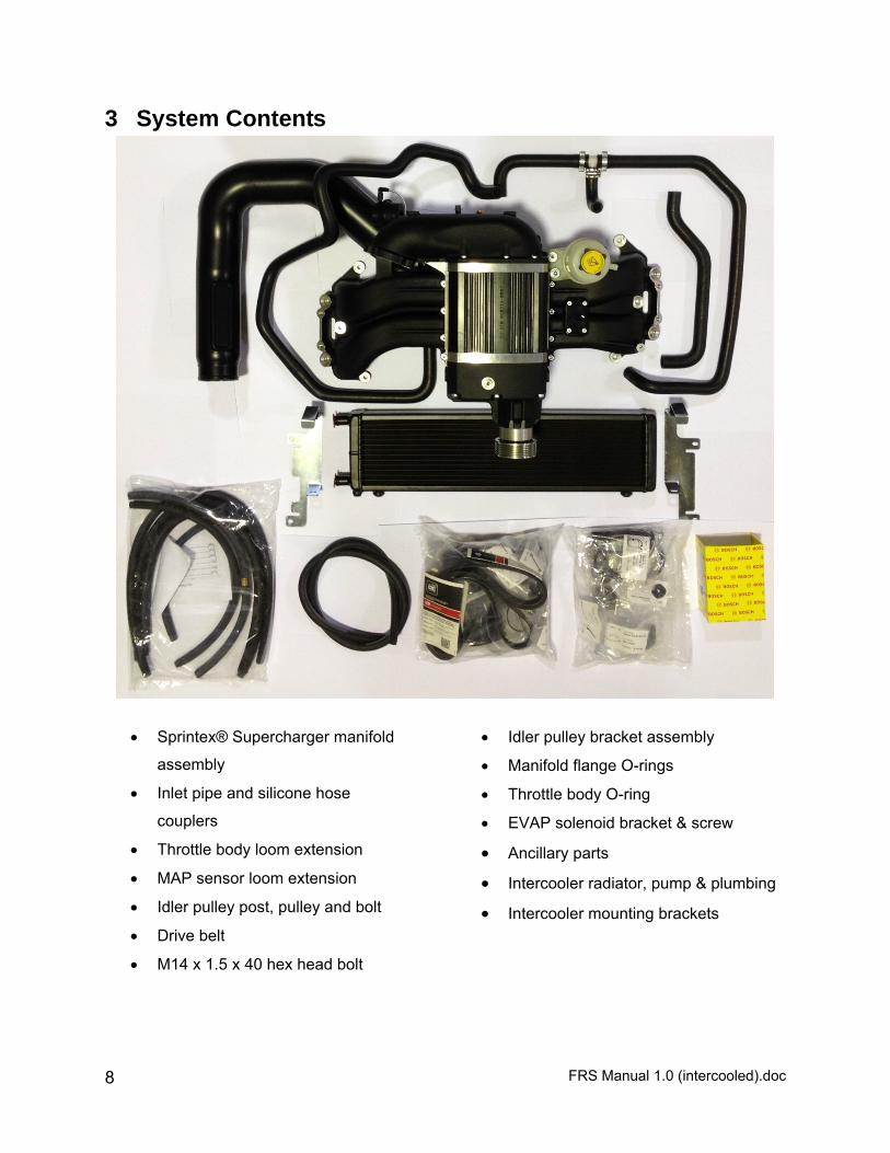
3 System Contents
Sprintex® Supercharger manifold
assembly
Inlet pipe and silicone hose
couplers
Throttle body loom extension
MAP sensor loom extension
Idler pulley post, pulley and bolt
Drive belt
M14 x 1.5 x 40 hex head bolt
Idler pulley bracket assembly
Manifold flange O-rings
Throttle body O-ring
EVAP solenoid bracket & screw
Ancillary parts
Intercooler radiator, pump & plumbing
Intercooler mounting brackets

FRS Manual 1.0 (intercooled).doc 9
4 Disassembly Instructions
SAFETY WARNING No unauthorized service or alteration may be undertaken to the Innovate Motorsports supercharger. Installation should be carried out in a workshop which is a safe and ventilated working environment with equipment and procedures compliant with local authority guidelines and legal requirements. Installers should ensure adequate hearing, eye, and physical protection is used at all times during the installation process. Installers should take reasonable precautions to avoid fatigue and closely follow the installation instructions during every installation. Innovate Motorsports recommends installation should not be carried out unsupervised. Innovate Motorsports, its directors, employees and agents will not accept liability for damage accident or injury resulting from the installation process. Safety warnings are also provided throughout this document.
4.1 Preparation Ensure that all components required to assemble the supercharger are available. Refer to the Parts Supplied section provided earlier. Ensure that all required tools are available. Please read the entire instruction manual prior to beginning the installation procedure. Ensure vehicle is located in a secure position with vehicle tires secured and handbrake applied. To avoid injury, Innovate Motorsports® recommends use of suitable a vehicle lift or axle stands when the vehicle is required to be lifted for access to. Stands should be positioned as per the vehicle Manufacturers Owners Handbook. SAFETY WARNING: Use Personal Protective Equipment such as safety glasses, gloves, etc. at all times and as necessary. Allow engine to cool prior to proceeding with disassembly to prevent scalding.
During disassembly and removal of components, take notes and ensure to label and store them safely; this will help with the reassembly.
Many of the photos shown in this document are of a typical FT86 right hand drive vehicle and are similar to a typical FT86 left hand drive vehicle.
FRS Manual 1.0 (intercooled).doc 10
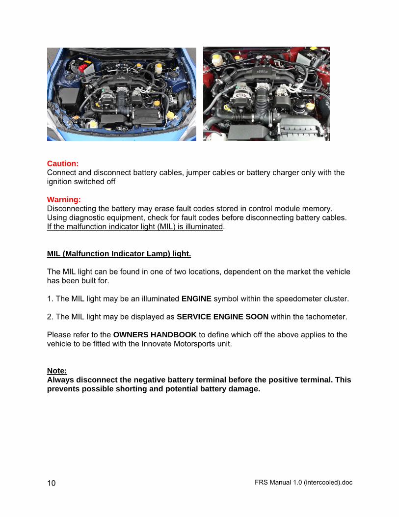
Caution: Connect and disconnect battery cables, jumper cables or battery charger only with the ignition switched off Warning: Disconnecting the battery may erase fault codes stored in control module memory. Using diagnostic equipment, check for fault codes before disconnecting battery cables. If the malfunction indicator light (MIL) is illuminated. MIL (Malfunction Indicator Lamp) light. The MIL light can be found in one of two locations, dependent on the market the vehicle has been built for. 1. The MIL light may be an illuminated ENGINE symbol within the speedometer cluster. 2. The MIL light may be displayed as SERVICE ENGINE SOON within the tachometer. Please refer to the OWNERS HANDBOOK to define which off the above applies to the vehicle to be fitted with the Innovate Motorsports unit. Note: Always disconnect the negative battery terminal before the positive terminal. This prevents possible shorting and potential battery damage.
FRS Manual 1.0 (intercooled).doc 11
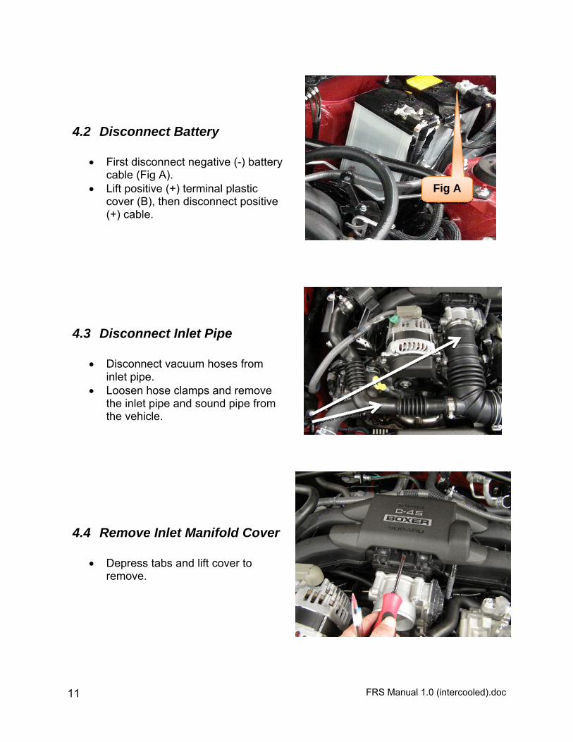
4.2 Disconnect Battery
First disconnect negative (-) battery cable (Fig A).
Lift positive (+) terminal plastic cover (B), then disconnect positive (+) cable.
4.3 Disconnect Inlet Pipe
Disconnect vacuum hoses from inlet pipe.
Loosen hose clamps and remove the inlet pipe and sound pipe from the vehicle.
4.4 Remove Inlet Manifold Cover
Depress tabs and lift cover to remove.
Fig A
FRS Manual 1.0 (intercooled).doc 12
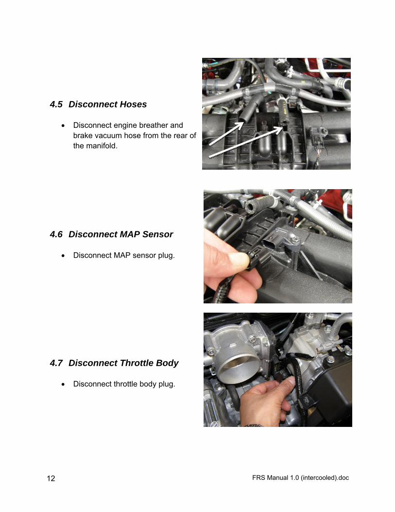
4.5 Disconnect Hoses
Disconnect engine breather and brake vacuum hose from the rear of the manifold.
4.6 Disconnect MAP Sensor
Disconnect MAP sensor plug.
4.7 Disconnect Throttle Body
Disconnect throttle body plug.
FRS Manual 1.0 (intercooled).doc 13
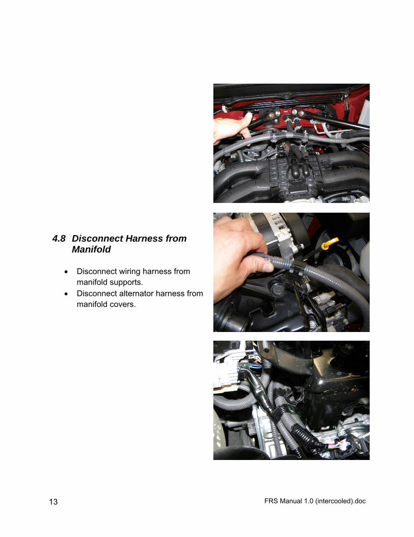
4.8 Disconnect Harness from Manifold
Disconnect wiring harness from
manifold supports. Disconnect alternator harness from
manifold covers.
FRS Manual 1.0 (intercooled).doc 14
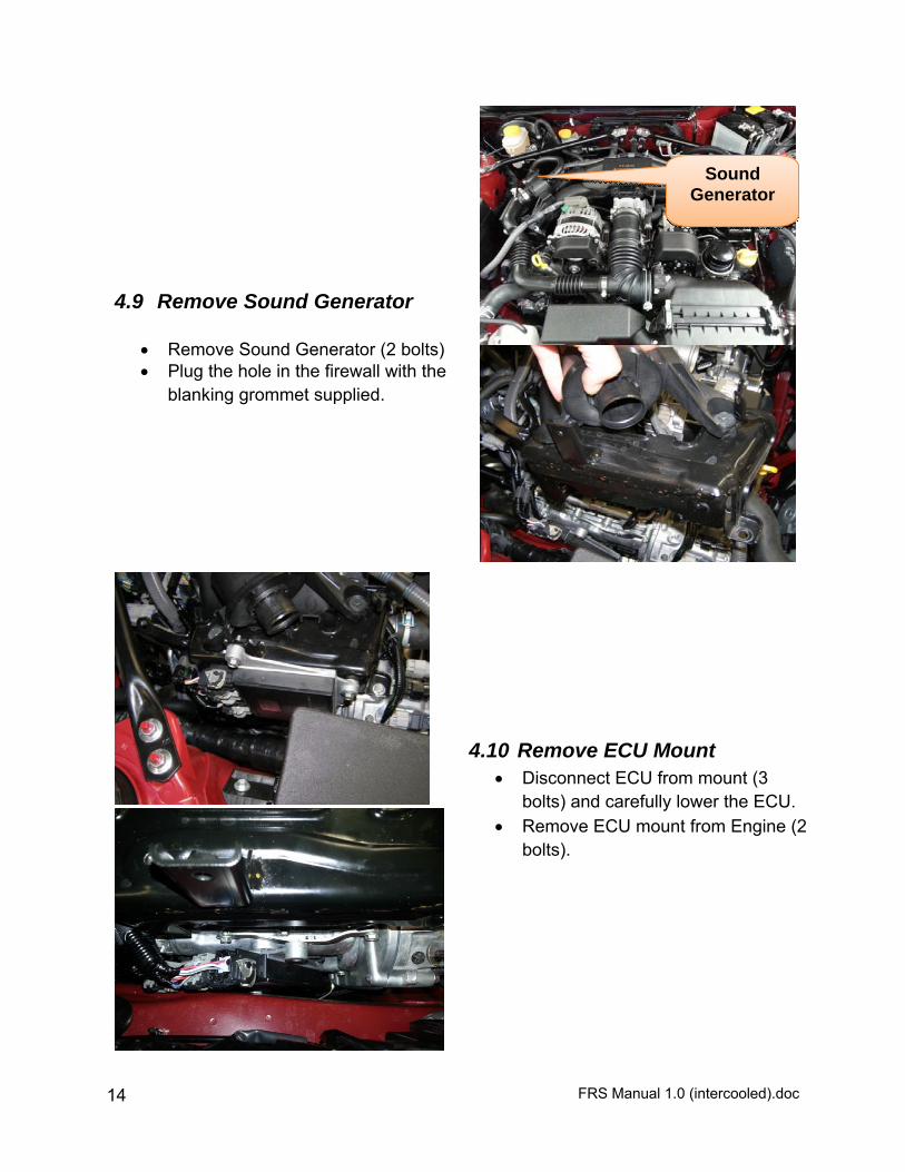
4.9 Remove Sound Generator
Remove Sound Generator (2 bolts) Plug the hole in the firewall with the
blanking grommet supplied.
4.10 Remove ECU Mount Disconnect ECU from mount (3
bolts) and carefully lower the ECU. Remove ECU mount from Engine (2
bolts).
Sound Generator

FRS Manual 1.0 (intercooled).doc 15
4.11 Disconnect Fuel Rail Support Disconnect EVAP solenoid hose from barb (A). Remove bolt from fuel rail support (B).
A
B
FRS Manual 1.0 (intercooled).doc 16
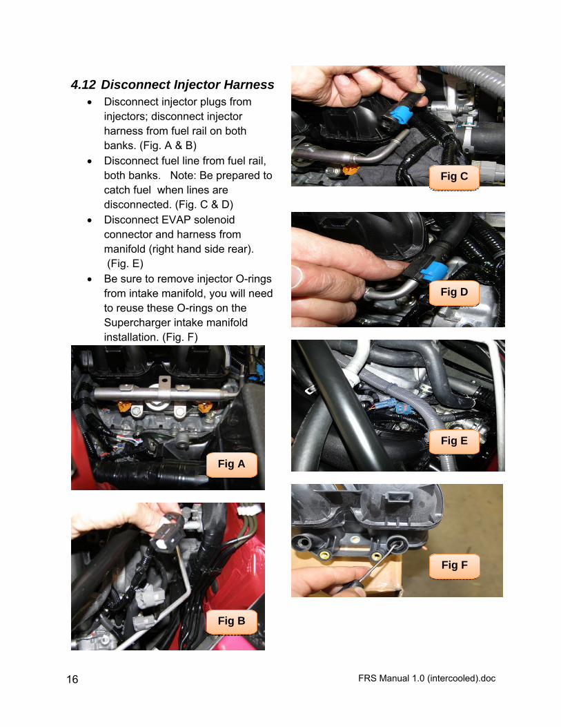
4.12 Disconnect Injector Harness Disconnect injector plugs from
injectors; disconnect injector harness from fuel rail on both banks. (Fig. A & B)
Disconnect fuel line from fuel rail, both banks. Note: Be prepared to catch fuel when lines are disconnected. (Fig. C & D)
Disconnect EVAP solenoid connector and harness from manifold (right hand side rear). (Fig. E)
Be sure to remove injector O-rings from intake manifold, you will need to reuse these O-rings on the Supercharger intake manifold installation. (Fig. F)
Fig A
Fig B
Fig C
Fig D
Fig E
Fig F
FRS Manual 1.0 (intercooled).doc 17
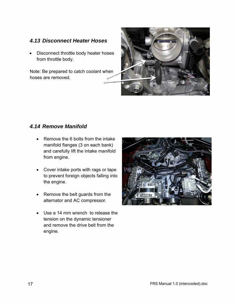
4.13 Disconnect Heater Hoses Disconnect throttle body heater hoses
from throttle body. Note: Be prepared to catch coolant when hoses are removed.
4.14 Remove Manifold
Remove the 6 bolts from the intake manifold flanges (3 on each bank) and carefully lift the intake manifold from engine.
Cover intake ports with rags or tape
to prevent foreign objects falling into the engine.
Remove the belt guards from the
alternator and AC compressor.
Use a 14 mm wrench to release the tension on the dynamic tensioner and remove the drive belt from the engine.
FRS Manual 1.0 (intercooled).doc 18
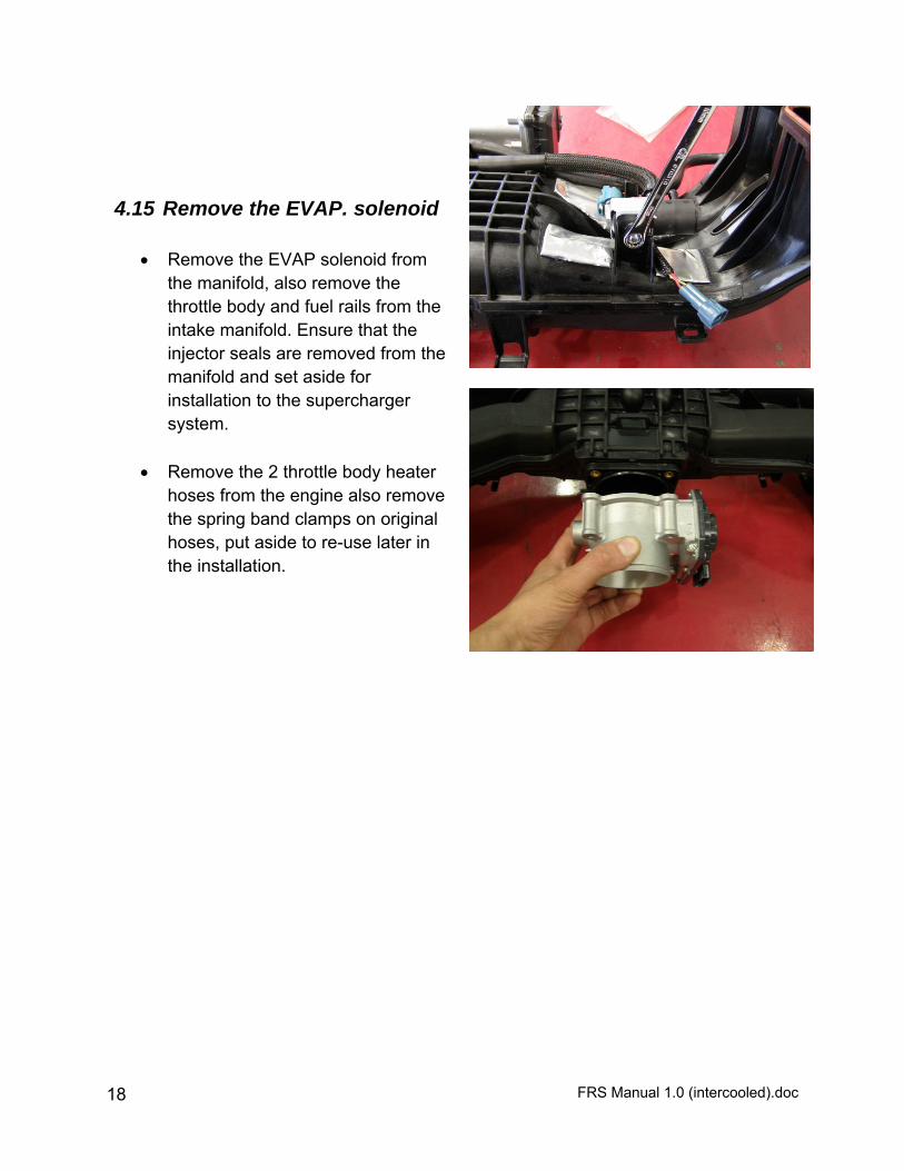
4.15 Remove the EVAP. solenoid
Remove the EVAP solenoid from the manifold, also remove the throttle body and fuel rails from the intake manifold. Ensure that the injector seals are removed from the manifold and set aside for installation to the supercharger system.
Remove the 2 throttle body heater
hoses from the engine also remove the spring band clamps on original hoses, put aside to re-use later in the installation.

FRS Manual 1.0 (intercooled).doc 19
5 Installation Instructions
SAFETY WARNING No unauthorized service or alteration may be undertaken to the Innovate Motorsports supercharger. Installation should be carried out in a workshop which is a safe and ventilated working environment with equipment and procedures compliant with local authority guidelines and legal requirements. Installers should ensure adequate hearing, eye, and physical protection is used at all times during the installation process. Installers should take reasonable precautions to avoid fatigue and closely follow the installation instructions during every installation. Innovate Motorsports recommends installation should not be carried out unsupervised. Innovate Motorsports, its directors, employees and agents will not accept liability for damage accident or injury resulting from the installation process. Safety warnings are also provided throughout this document.
5.1 Install Engine Breather Hose Extension
Attach the ½” inch ID. 700mm
long engine breather extension hose to the OEM engine breather hose, route the supplied hose as shown in picture. The extended hose will connect to the supercharger inlet later in the installation
Extension Hose
OEM Engine Breather Hose
FRS Manual 1.0 (intercooled).doc 20
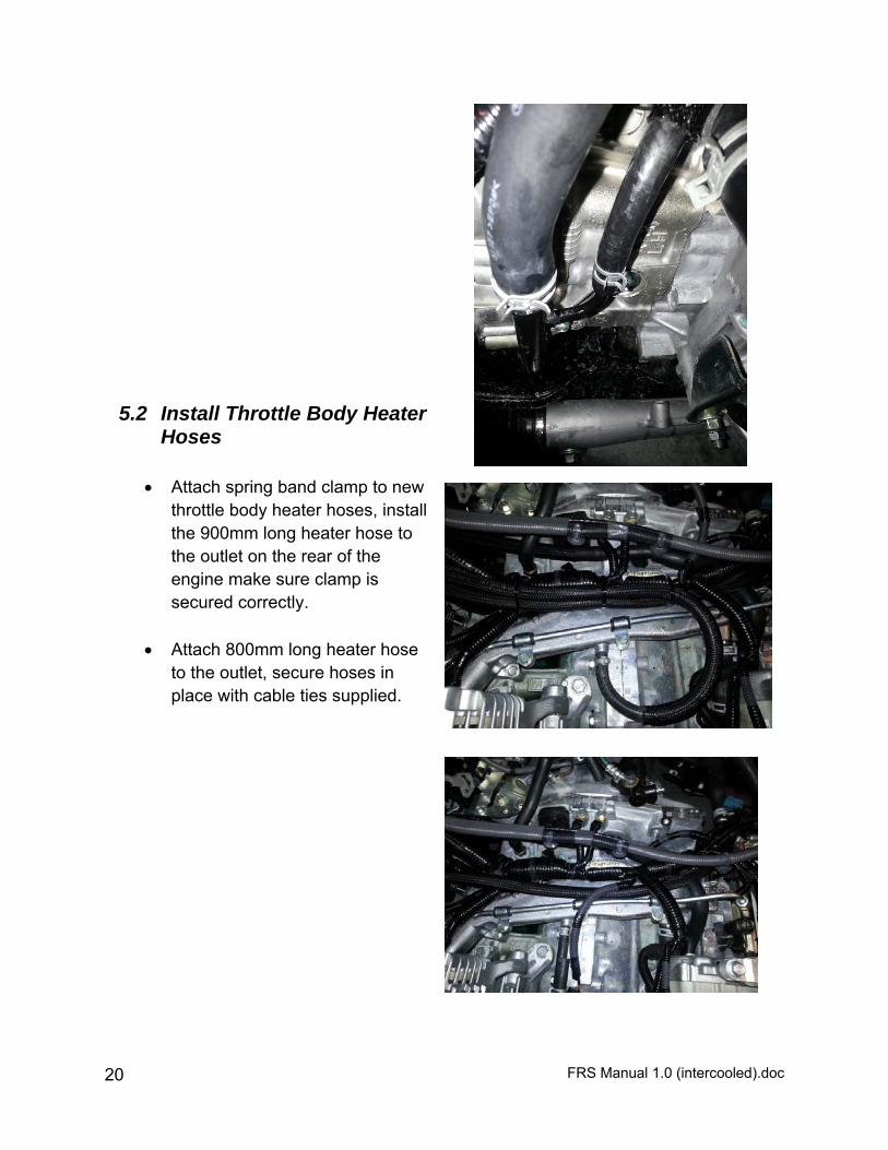
5.2 Install Throttle Body Heater Hoses
Attach spring band clamp to new
throttle body heater hoses, install the 900mm long heater hose to the outlet on the rear of the engine make sure clamp is secured correctly.
Attach 800mm long heater hose
to the outlet, secure hoses in place with cable ties supplied.
FRS Manual 1.0 (intercooled).doc 21
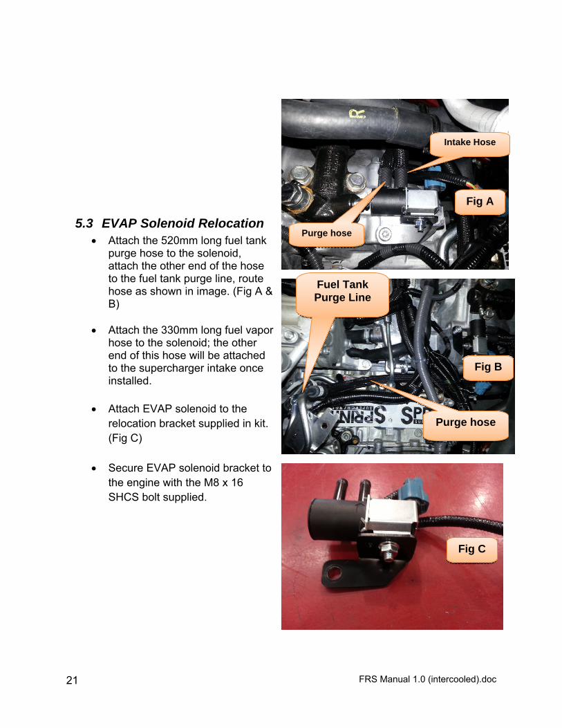
5.3 EVAP Solenoid Relocation Attach the 520mm long fuel tank
purge hose to the solenoid, attach the other end of the hose to the fuel tank purge line, route hose as shown in image. (Fig A & B)
Attach the 330mm long fuel vapor
hose to the solenoid; the other end of this hose will be attached to the supercharger intake once installed.
Attach EVAP solenoid to the
relocation bracket supplied in kit. (Fig C)
Secure EVAP solenoid bracket to
the engine with the M8 x 16 SHCS bolt supplied.
Purge hose
Intake Hose
Fuel Tank Purge Line
Purge hose
Fig A
Fig B
Fig C
FRS Manual 1.0 (intercooled).doc 22
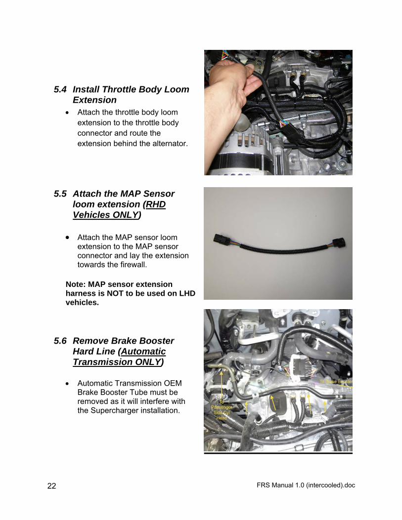
5.4 Install Throttle Body Loom Extension
Attach the throttle body loom extension to the throttle body connector and route the extension behind the alternator.
5.5 Attach the MAP Sensor loom extension (RHD Vehicles ONLY)
Attach the MAP sensor loom
extension to the MAP sensor connector and lay the extension towards the firewall.
Note: MAP sensor extension harness is NOT to be used on LHD vehicles.
5.6 Remove Brake Booster Hard Line (Automatic Transmission ONLY)
Automatic Transmission OEM
Brake Booster Tube must be removed as it will interfere with the Supercharger installation.
FRS Manual 1.0 (intercooled).doc 23
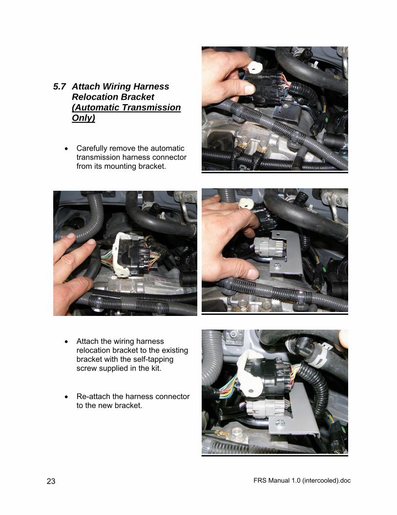
5.7 Attach Wiring Harness Relocation Bracket (Automatic Transmission Only)
Carefully remove the automatic
transmission harness connector from its mounting bracket.
Attach the wiring harness
relocation bracket to the existing bracket with the self-tapping screw supplied in the kit.
Re-attach the harness connector to the new bracket.

FRS Manual 1.0 (intercooled).doc 24
5.8 Install Idler Pulley Mount Remove alternator mounting bolt. Assemble idler pulley in the order
illustrated in Fig A. using replacement alternator mounting bolt supplied.
Bolt idler pulley assembly to
alternator bracket. (Blue Loctite is recommended)
Alternator Mounting Bolt
1
2 3 4
Replacement Alternator Mounting Bolt Fig A
FRS Manual 1.0 (intercooled).doc 25
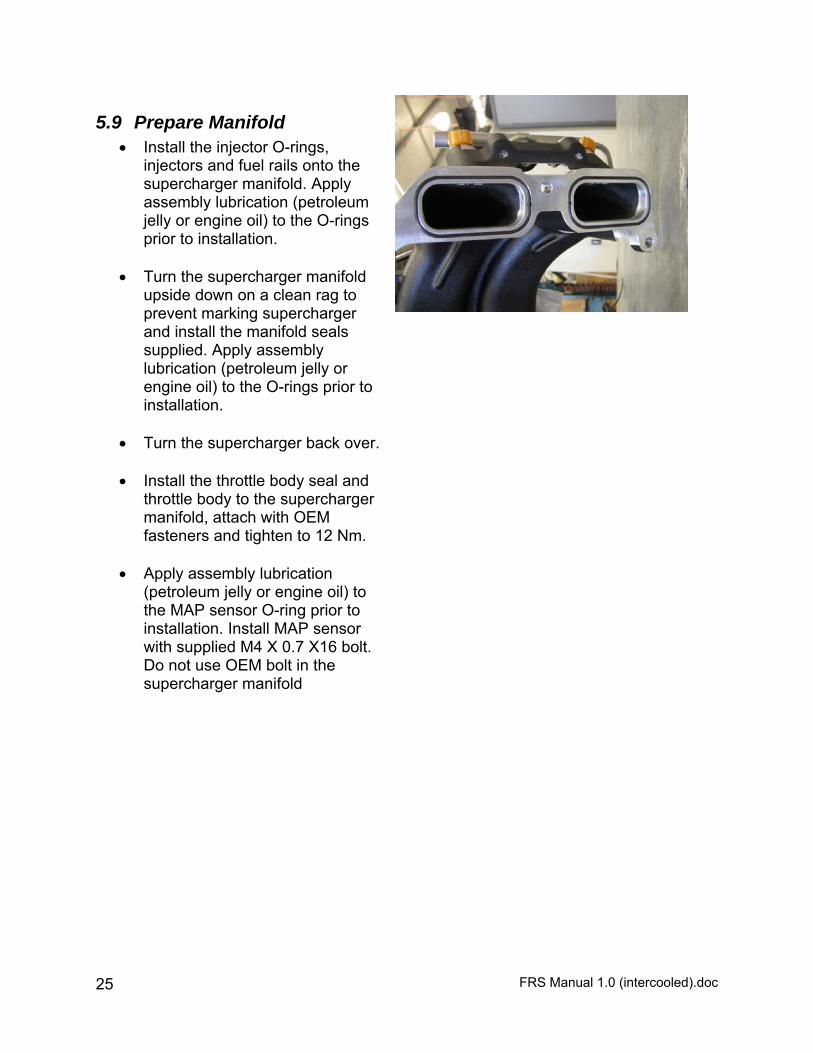
5.9 Prepare Manifold Install the injector O-rings,
injectors and fuel rails onto the supercharger manifold. Apply assembly lubrication (petroleum jelly or engine oil) to the O-rings prior to installation.
Turn the supercharger manifold
upside down on a clean rag to prevent marking supercharger and install the manifold seals supplied. Apply assembly lubrication (petroleum jelly or engine oil) to the O-rings prior to installation.
Turn the supercharger back over. Install the throttle body seal and
throttle body to the supercharger manifold, attach with OEM fasteners and tighten to 12 Nm.
Apply assembly lubrication
(petroleum jelly or engine oil) to the MAP sensor O-ring prior to installation. Install MAP sensor with supplied M4 X 0.7 X16 bolt. Do not use OEM bolt in the supercharger manifold

FRS Manual 1.0 (intercooled).doc 26
5.10 Test Fit The Supercharger Manifold
Carefully lower the supercharger manifold into place (2 PERSON LIFT) and check the clearance around the alternator. Due to normal fluctuation in the OEM components, it may be necessary to file the corner of the alternator bracket to make sure that the supercharger manifold is not prevented from sitting flat on the intake face of the cylinder heads. This step, if needed, should be simple with a large flat file and take less than 1 minute.
Make sure that the intake ports are
covered before filing the corner of the alternator support. (Fig A)
Use a vacuum cleaner to collect
any metal debris before removing tape or rags from the intake runners prior to fitting the manifold.
Position throttle body plug so it can
be accessed once manifold is in place.
Lower the manifold into place and
secure the manifold in place with the 6 original OEM fasteners. Torque to 18 ft lb (25 Nm).
It is recommended to re-torque these 6 intake manifold bolts after 500 miles.
Secure the manifold with the M14 x
1.5 x 40 Hex Head Bolt (Fig B).
Fig A
Fig B

FRS Manual 1.0 (intercooled).doc 27
5.11 Attach throttle body connector
Connect throttle plug connector to
throttle body.
5.12 Attach heater hoses
Connect the throttle body heater hoses to the throttle body, making sure hose clamps are installed correctly.
5.13 Install drive belt
Use a 14 mm wrench to release the tension on the dynamic tensioner and install new drive belt. Follow belt routing diagram and make sure that the belt is properly aligned on each pulley.
FRS Manual 1.0 (intercooled).doc 28
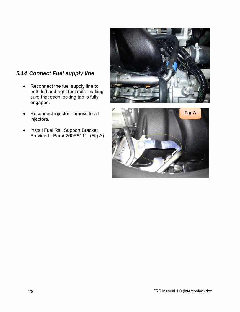
5.14 Connect Fuel supply line
Reconnect the fuel supply line to both left and right fuel rails, making sure that each locking tab is fully engaged.
Reconnect injector harness to all
injectors.
Install Fuel Rail Support Bracket Provided - Part# 260P8111 (Fig A)
Fig A
FRS Manual 1.0 (intercooled).doc 29
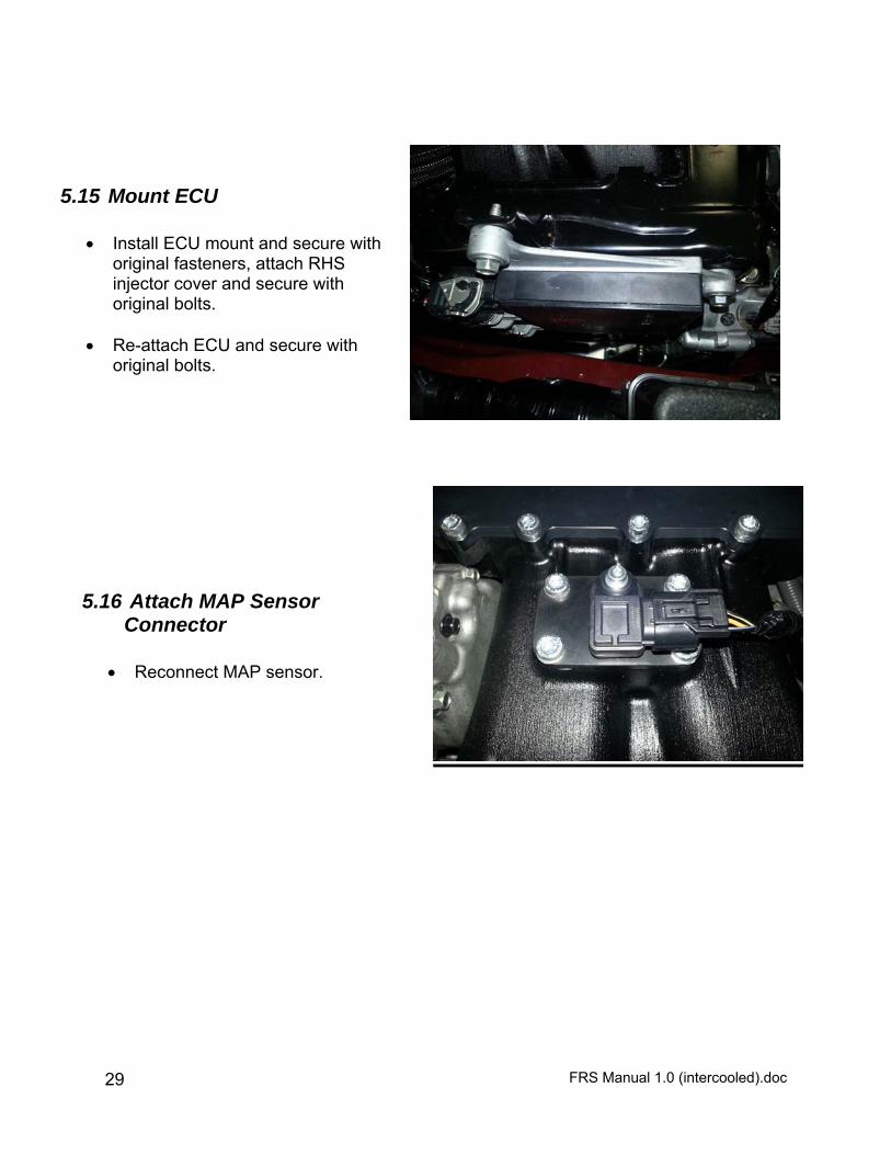
5.15 Mount ECU
Install ECU mount and secure with original fasteners, attach RHS injector cover and secure with original bolts.
Re-attach ECU and secure with
original bolts.
5.16 Attach MAP Sensor Connector
Reconnect MAP sensor.
FRS Manual 1.0 (intercooled).doc 30
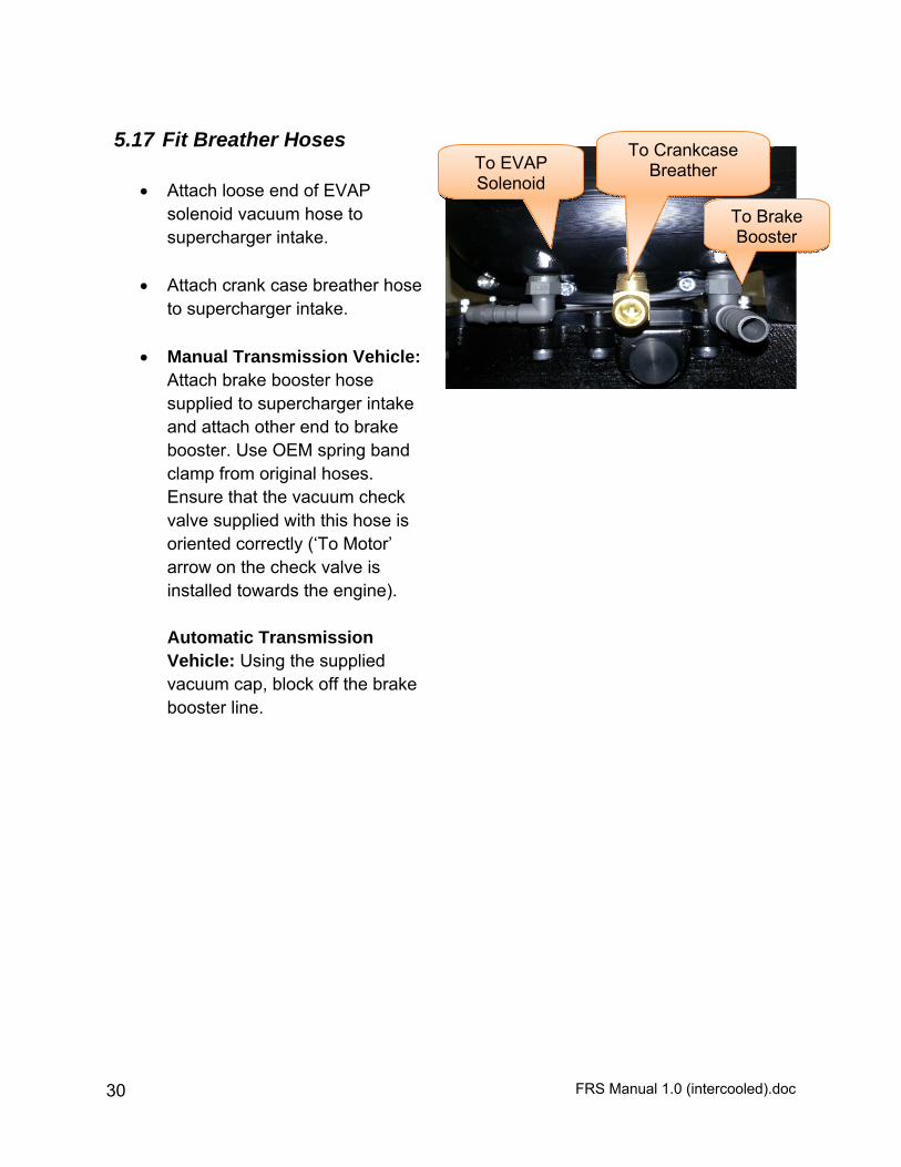
5.17 Fit Breather Hoses
Attach loose end of EVAP solenoid vacuum hose to supercharger intake.
Attach crank case breather hose to supercharger intake.
Manual Transmission Vehicle:
Attach brake booster hose supplied to supercharger intake and attach other end to brake booster. Use OEM spring band clamp from original hoses. Ensure that the vacuum check valve supplied with this hose is oriented correctly (‘To Motor’ arrow on the check valve is installed towards the engine).
Automatic Transmission Vehicle: Using the supplied vacuum cap, block off the brake booster line.
To Crankcase Breather
To Brake Booster
To EVAP Solenoid
FRS Manual 1.0 (intercooled).doc 31
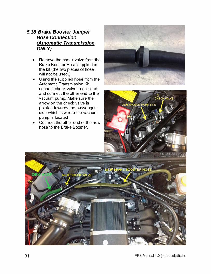
5.18 Brake Booster Jumper Hose Connection (Automatic Transmission ONLY)
Remove the check valve from the
Brake Booster Hose supplied in the kit (the two pieces of hose will not be used.)
Using the supplied hose from the Automatic Transmission Kit, connect check valve to one end and connect the other end to the vacuum pump. Make sure the arrow on the check valve is pointed towards the passenger side which is where the vacuum pump is located.
Connect the other end of the new hose to the Brake Booster.

FRS Manual 1.0 (intercooled).doc 32
6 Heat Exchanger Installation
6.1 Prepare Heat Exchanger
Apply thread sealant to the thread of the elbow upon assembly. Install the plastic elbow to the heat exchanger. (may be preinstalled)
Install 2 radiator support pins
Radiator Support
Pin
Radiator Support
Elbow
Top Bracket
Bottom Bracket
FRS Manual 1.0 (intercooled).doc 33
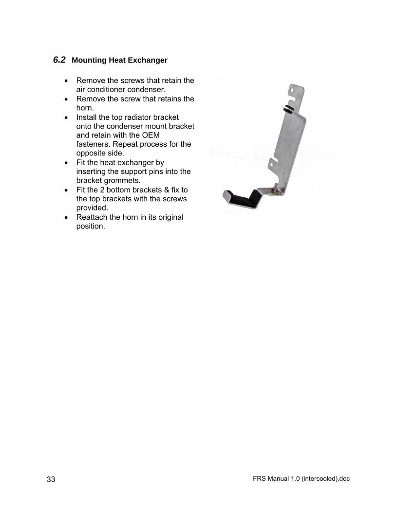
6.2 Mounting Heat Exchanger
Remove the screws that retain the air conditioner condenser.
Remove the screw that retains the horn.
Install the top radiator bracket onto the condenser mount bracket and retain with the OEM fasteners. Repeat process for the opposite side.
Fit the heat exchanger by inserting the support pins into the bracket grommets.
Fit the 2 bottom brackets & fix to the top brackets with the screws provided.
Reattach the horn in its original position.
FRS Manual 1.0 (intercooled).doc 34
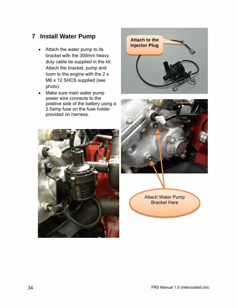
7 Install Water Pump
Attach the water pump to its bracket with the 300mm heavy duty cable tie supplied in the kit. Attach the bracket, pump and loom to the engine with the 2 x M6 x 12 SHCS supplied (see photo).
Make sure main water pump power wire connects to the positive side of the battery using a 2.5amp fuse on the fuse holder provided on harness.
Attach to the Injector Plug
Attach Water Pump Bracket Here
FRS Manual 1.0 (intercooled).doc 35
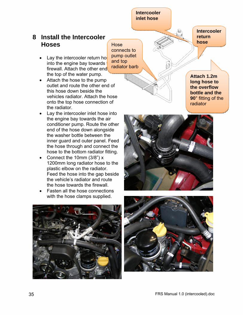
8 Install the Intercooler Hoses
Lay the intercooler return hose
into the engine bay towards the firewall. Attach the other end to the top of the water pump.
Attach the hose to the pump outlet and route the other end of this hose down beside the vehicles radiator. Attach the hose onto the top hose connection of the radiator.
Lay the intercooler inlet hose into the engine bay towards the air conditioner pump. Route the other end of the hose down alongside the washer bottle between the inner guard and outer panel. Feed the hose through and connect the hose to the bottom radiator fitting.
Connect the 10mm (3/8”) x 1200mm long radiator hose to the plastic elbow on the radiator. Feed the hose into the gap beside the vehicle’s radiator and route the hose towards the firewall.
Fasten all the hose connections with the hose clamps supplied.
Hose connects to pump outlet and top radiator barb
Intercooler return hose
Intercooler inlet hose
Attach 1.2m long hose to the overflow bottle and the 90° fitting of the radiator

FRS Manual 1.0 (intercooled).doc 36
Make a cut out (35mm wide x 40mm high) in the RHS plastic panel next to the air conditioner condensor. This will allow the bottom radiator hose to pass through when the radiator is installed.
FRS Manual 1.0 (intercooled).doc 37
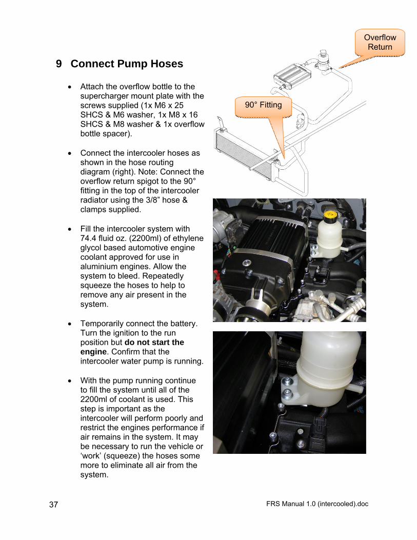
9 Connect Pump Hoses Attach the overflow bottle to the
supercharger mount plate with the screws supplied (1x M6 x 25 SHCS & M6 washer, 1x M8 x 16 SHCS & M8 washer & 1x overflow bottle spacer).
Connect the intercooler hoses as
shown in the hose routing diagram (right). Note: Connect the overflow return spigot to the 90° fitting in the top of the intercooler radiator using the 3/8” hose & clamps supplied.
Fill the intercooler system with
74.4 fluid oz. (2200ml) of ethylene glycol based automotive engine coolant approved for use in aluminium engines. Allow the system to bleed. Repeatedly squeeze the hoses to help to remove any air present in the system.
Temporarily connect the battery.
Turn the ignition to the run position but do not start the engine. Confirm that the intercooler water pump is running.
With the pump running continue
to fill the system until all of the 2200ml of coolant is used. This step is important as the intercooler will perform poorly and restrict the engines performance if air remains in the system. It may be necessary to run the vehicle or ‘work’ (squeeze) the hoses some more to eliminate all air from the system.
Overflow Return
90° Fitting
FRS Manual 1.0 (intercooled).doc 38
Check all the intercooler hose connections for leaks.
Disconnect the battery again. Refit the vehicles under body
trays.
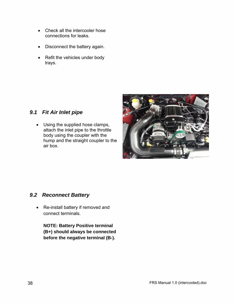
9.1 Fit Air Inlet pipe
Using the supplied hose clamps, attach the inlet pipe to the throttle body using the coupler with the hump and the straight coupler to the air box.
9.2 Reconnect Battery
Re-install battery if removed and connect terminals.
NOTE: Battery Positive terminal (B+) should always be connected before the negative terminal (B-).
FRS Manual 1.0 (intercooled).doc 39
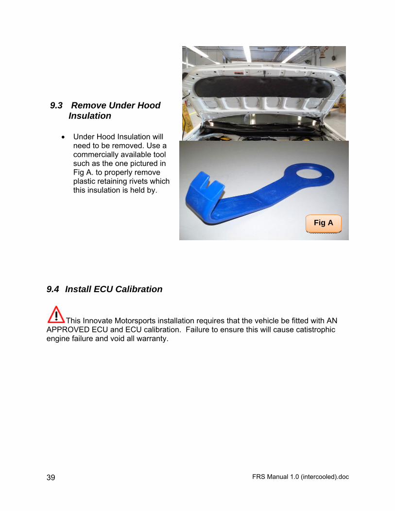
9.3 Remove Under Hood Insulation
Under Hood Insulation will
need to be removed. Use a commercially available tool such as the one pictured in Fig A. to properly remove plastic retaining rivets which this insulation is held by.
9.4 Install ECU Calibration
This Innovate Motorsports installation requires that the vehicle be fitted with AN APPROVED ECU and ECU calibration. Failure to ensure this will cause catistrophic engine failure and void all warranty.
Fig A
FRS Manual 1.0 (intercooled).doc 40
10 Pre Test-Drive Inspection
10.1 Pre-Start Inspection Supercharger comes prefilled with gear oil. Verify correct gear oil level.
Refer to instructions on page 42.
Ensure coolant is at correct level.
Ensure engine oil is at correct level.
Ensure vehicle has fresh 91 Octane (or higher) Premium Unleaded Pump fuel.
Ensure the belt is aligned.
Ensure the air filter is clean.
Check & replace spark plugs, if necessary. Set gap to factory spec. 0.050”.
10.2 Engine Warm Up Start engine and allow it to run until engine reaches normal operating
temperature.
Check for oil leaks.
10.3 Road Test Vehicle Road test vehicle.
Recheck all joints and connections for leaks –rectify as needed.

FRS Manual 1.0 (intercooled).doc 41
11 Supercharger System Maintenance
11.1 Drive Belt It is recommended that the supercharger drive belt
be checked at every regular service and be replaced at 50,000 km (30,000 miles) or 2 years, whichever occurs first. The part number for the replacement belt is K061015.
Use a 14mm wrench to release the dynamic tensioner and remove the belt.
Tensioner Arm may be locked
into position by a small Allen Wrench to provide ease of belt removal/installation.
Dynamic tensioner
Allen Wrench
FRS Manual 1.0 (intercooled).doc 42
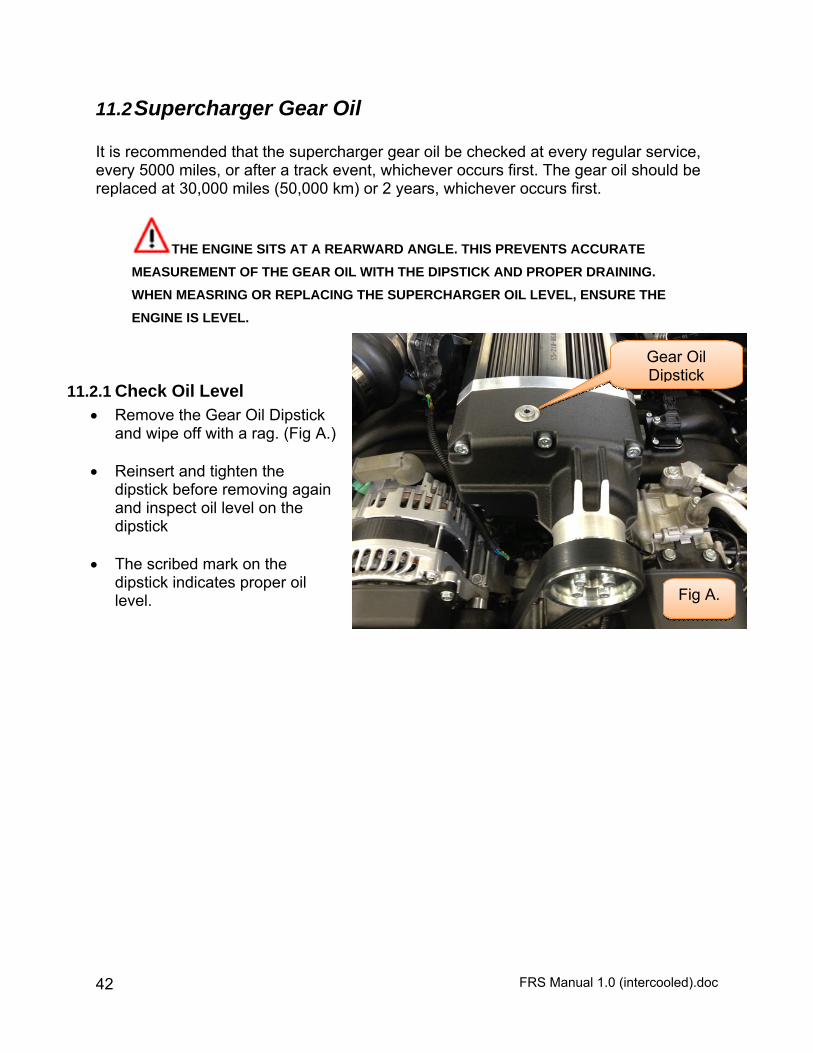
11.2 Supercharger Gear Oil It is recommended that the supercharger gear oil be checked at every regular service, every 5000 miles, or after a track event, whichever occurs first. The gear oil should be replaced at 30,000 miles (50,000 km) or 2 years, whichever occurs first.
THE ENGINE SITS AT A REARWARD ANGLE. THIS PREVENTS ACCURATE
MEASUREMENT OF THE GEAR OIL WITH THE DIPSTICK AND PROPER DRAINING.
WHEN MEASRING OR REPLACING THE SUPERCHARGER OIL LEVEL, ENSURE THE
ENGINE IS LEVEL.
11.2.1 Check Oil Level Remove the Gear Oil Dipstick
and wipe off with a rag. (Fig A.) Reinsert and tighten the
dipstick before removing again and inspect oil level on the dipstick
The scribed mark on the
dipstick indicates proper oil level.
Gear Oil Dipstick
Fig A.

FRS Manual 1.0 (intercooled).doc 43
11.2.2 Replace Gear Oil Remove the Gear Oil Dipstick.
(Fig A.) Using a syringe to draw out the
old gear oil, drain the supercharger’s gearbox.
Using Redline 75W90 NS Gear
Oil or equivalent fill with exactly 5.31 oz (157 mil.)
Check oil level with dipstick.
Gear Oil Dipstick
Fig A.
FRS Manual 1.0 (intercooled).doc 44
12 LIMITED WARRANTY Who is the Warrantor The warrantor for this limited warranty is Innovate Motorsports, 8 Mason, Irvine, CA 92618. Which Products are Covered This limited warranty applies to Innovate Motorsports superchargers and supercharger systems sold and normally operated in the United States, Canada, and Mexico (the “Product”).
When Warranty Begins The warranty period begins on date the Product is sold to the first retail purchaser. Limitations Repair, replacement, or a refund of not more than the retail price of the Product are the exclusive remedies under this limited warranty or any implied warranties. Innovate Motorsports does not authorize any person to create for it any other obligation or liability in connection with the Product. Warranty coverage is limited to the first retail purchaser of the Product. This limited warranty is not transferrable and terminates upon the first retail purchaser’s sale or other transfer of the Product. Any implied warranty or merchantability or fitness for a particular purpose is limited to the duration of this written warranty. Some states and jurisdictions do not allow limitations on how long an implied warranty lasts, so this limitation may not apply to you. Your Rights Under State Law This warranty gives you specific legal rights, and you may also have other rights that vary from state to state and jurisdiction to jurisdiction. WHAT IS COVERED AND HOW LONG Basic Warranty Innovate Motorsports warrants to the first retail purchaser of the Product that (1) the Product will be free from defects in materials and workmanship during the period of 12 months or 12,000 miles, whichever comes first, from the date of purchase (the “Warranty Period”). This warranty is an express limited warranty. If the Product fails during the Warranty Period under normal operating conditions as a result of a defect in materials or workmanship, at Innovate Motorsports’ option, it will either (1) repair the Product, using new, used or refurbished replacement parts, or (2) replace the Product with a new, used or refurbished equivalent Product, or (3) refund not more than the retail price of the Product. You must pay the costs of returning any Product to Innovate Motorsports for a warranty claim. Innovate Motorsports is not responsible for any freight or handling charges on Products returned to it. If a Product returned to Innovate Motorsports is
FRS Manual 1.0 (intercooled).doc 45
returned for a reason covered by this limited warranty, Innovate Motorsports will pay for ground shipping charges only to return the Product to you. The decision whether the Product should be repaired or replaced or whether a refund of not more than the retail price of the Product should be given will be made by Innovate Motorsports. Innovate Motorsports neither assumes nor authorizes any person to assume for it any other liability in connection with the sale of the Product. This limited warranty is subject to the exceptions indicated under “What is Not Covered” section below.
WHAT IS NOT COVERED This warranty does not cover damage, defect, or failure resulting directly or indirectly from any of the following:
Use of contaminated, poor quality or incorrect fuels; Alteration, modification or disassembly; Improper or incorrectly performed installation or repairs, or when the
Product is used in an application for which it was not designed or approved;
Use of an incorrect pulley size or failure to regularly inspect and replace the pulley belt;
Abuse, negligence or neglect; Misuse – for example, racing; Lack of or improper maintenance; Use of non-genuine Innovate Motorsports parts; Repair, modification or any other action performed by anyone other
than a Innovate Motorsports approved repairer;
A matter outside the control of Innovate Motorsports or its employees and contractors (for example a defect caused by the failure of a product supplied to you by a person that is unrelated to us such as the manufacturer or your motor vehicle);
Corrosion from environmental conditions or chemical treatments; Fire, accident or theft; or Act of God.
This warranty also does not cover the following: Normal Wear and Tear Noise, vibration, cosmetic conditions and other deterioration caused by normal wear and tear. Maintenance Expense Normal maintenance services such as changing oils, belts, injectors and any similar consumable parts.

FRS Manual 1.0 (intercooled).doc 46
Vehicles With Altered Odometer Failure of a Product installed on a vehicle on which the odometer has been altered so that actual vehicle mileage cannot be readily determined. Vehicles With Unknown Vehicle Identification Number Any vehicle for which the original factory-assigned vehicle identification number cannot be determined. Salvage or Total-Loss Vehicles Any vehicle that has ever been issued a “salvage” title or similar title under any state’s law; or has ever been declared a “total loss” or equivalent by a financial institution or insurer, such as by payment for a claim in lieu of repairs because the cost of repairs exceeded the cash value of the vehicle. Incidental and Consequential Damages Incidental or consequential damages associated with a Product failure. Such damages include, but are not limited to, inconvenience; the cost of removal, installation, transportation or towing; labor; telephone calls and lodging; the loss of time; the loss of personal or commercial property; destruction of other components; and the loss of pay, profits, business or other opportunities. Some states and jurisdictions do not allow the exclusion or limitation of incidental or consequential damages, so the above limitation or exclusion may not apply to you. Disclaimer of Extra Expenses and Damages The performance of necessary repairs, replacement, or refund of not more than the retail price of the Product are the exclusive remedies under this limited warranty and under any implied warranty. Innovate Motorsports does not authorize any person to create for it any other obligation or liability in connection with the Product. Innovate Motorsports shall not be liable for incidental or consequential damages resulting from breach of this written warranty or any implied warranty. Any implied warranty of merchantability or fitness for a particular purpose is limited to the duration of this written warranty, except in states where this limitation is not allowed. Some states and jurisdictions do not allow the exclusion or limitation of incidental or consequential damages, so the above limitation or exclusion may not apply to you. WARRANTY CLAIMS To make a warranty claim contact Innovate Motorsports at 8 Mason, Irvine, CA 92618. To make a warranty claim, you must provide proof of your purchase of the Product. While necessary maintenance or repairs on the Product can be performed by any company, we recommend that you use only authorized Innovate Motorsports repairers. Improper or incorrectly performed maintenance or repair voids this limited warranty. A list of approved repairers is available from us by contacting the Innovate Motorsports.
FRS Manual 1.0 (intercooled).doc 47
13 Revision History 1.0 8/31/2013 - Initial Release

FRS Manual 1.0 (intercooled).doc 48
FRS Manual 1.0 (intercooled).doc 49
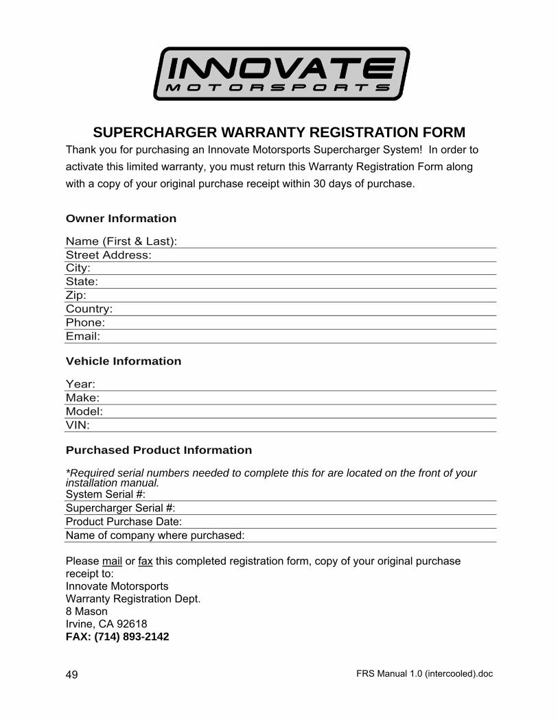
SUPERCHARGER WARRANTY REGISTRATION FORM Thank you for purchasing an Innovate Motorsports Supercharger System! In order to
activate this limited warranty, you must return this Warranty Registration Form along
with a copy of your original purchase receipt within 30 days of purchase.
Owner Information Name (First & Last): Street Address: City: State: Zip: Country: Phone: Email: Vehicle Information Year: Make: Model: VIN: Purchased Product Information *Required serial numbers needed to complete this for are located on the front of your installation manual. System Serial #: Supercharger Serial #: Product Purchase Date: Name of company where purchased: Please mail or fax this completed registration form, copy of your original purchase receipt to: Innovate Motorsports Warranty Registration Dept. 8 Mason Irvine, CA 92618 FAX: (714) 893-2142