For Industrial Maintenance and Consumer Servicing Professionals...
44
For Industrial Maintenance and Consumer Servicing Professionals July, 1980 $2.25 Electronic servicing Antenna roundup issue Installing TVantennas Testin diodes
Transcript of For Industrial Maintenance and Consumer Servicing Professionals...
For Industrial Maintenance and Consumer Servicing Professionals July, 1980 $2.25
Electronic servicing
Antenna roundup issueInstalling TVantennas
Testin diodes
General Electrichas just publishedyour favorite book.
Again.We have added over 90 pages of MRO
types and related information. And we havepresented ICs in easier -to -use fashion thanever before. The latter are now shown in chartform and are grouped under various applica-tion headings-such as Preamps-indescending order of power dissipation.
As before, our unique parts ID numberingsystem tells you at a glance almost all youneed to know when making a replacement.
Thus, GE5ZD3.3 stands for a 5 -watt, 3.3 -voltzener diode by General Electric.
Keeping up with the industry is howGeneral Electric helps you stay in touch. Withtechnical literature like this updated Semicon-ductor Guide...and with the replacement partsyou need for the equipment you service.
For your copy of the book you asked us topublish again, see your authorized GE distrib-utor today.
Tube Products Department-Owensboro, Kentucky 42301
GENERAL ELECTRIC
Electronic ServicingEditorial, advertising and circulation corre-spondence should be addressed to P.O.Box 12901, Overland Park, KS 66212 (a
suburb of Kansas City, MO); (913) 888-4664.
EDITORIALBill Rhodes, Editorial DirectorCarl Babcoke, Consumer Servicing
ConsultantMary Thornbrugh, Associate Editor
ARTDudley Rose, Art DirectorLinda S. Franzblau, Graphic Designer
CIRCULATIONJohn C. Arnst, DirectorEvelyn Rogers, Manager
ADMINISTRATIONGeorge H. Seferovich, PresidentGeorge Laughead, Publisher
ADVERTISINGGreg Garrison, National Sales ManagerDee Unger, Production
Regional advertising sales offices listednear Advertiser's Index.
" Member.ABP American Business Press
AEC
Member,Audit Bureauof Circulation
ELECTRONIC SERVICING (USPS 462-050)(with which is combined PF Reporter) ispublished monthly by Intertec PublishingCorp., 9221 Quivira Road, Overland Park,KS 66212. Controlled Circulation Postagepaid at Shawnee Mission, KS 66201. SendForm 3579 to P.O. Box 12901, OverlandPark. KS 66212.
ELECTRONIC SERVICING is edited fortechnicians who repair home -entertainmentelectronic equipment (such as TV, radio,tape, stereo and record players) and forindustrial technicians who repair defectiveproduction -line merchandise, test equip-ment, or industrial controls in factories.
Subscription prices to qualified sub-scribers: 1 year-$12, 2 years-$19, 3
years-$24, in the USA and its posses-siones. All other foreign countries: 1
year-$15, 2 years-$25. Subscriptionprices to all others: 1 year-$25, 2
years-$50, in the USA and its posses-sions. All other fcreign countries: 1
year-$34, 2 years-$68. Single copy price$2.25; back copies $3.00. Adjustmentnecessitated by subscription termination tosingle copy rate. Allow 6 to 8 weeksdelivery for change of address. Allow 6 to 8weeks for new subscriptions.
INTERTEC PUBLISHING CORP.
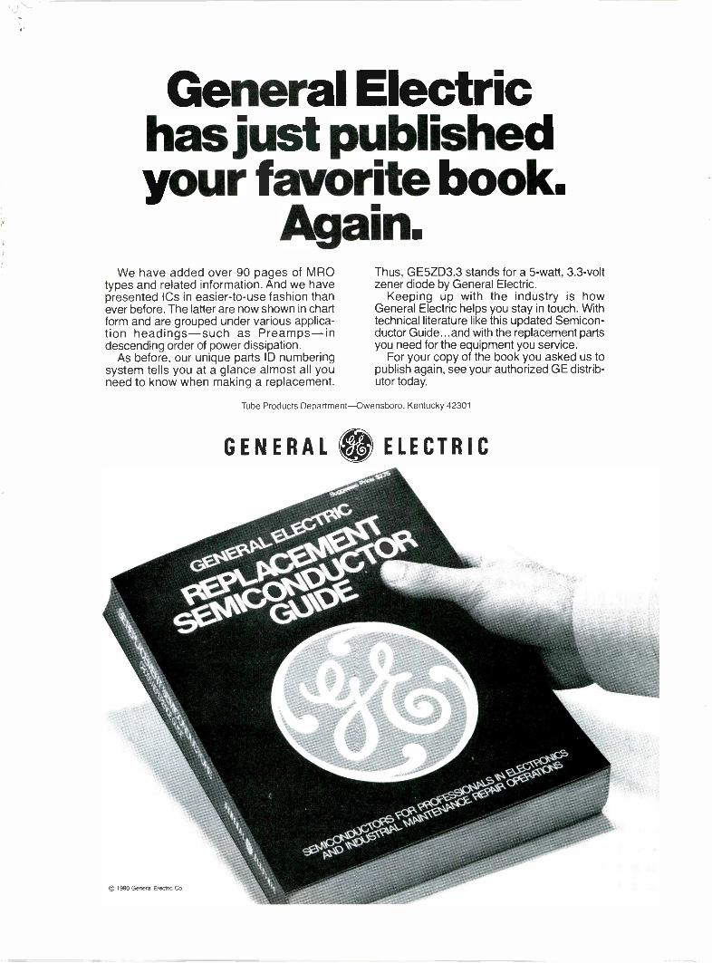
Next month in
Electronic servicing
Industrial Maintenance
MRO shops-maintenance and test equipment Semiconductor source guide
Consumer Servicing
1981 TV receiver features RCA CTC99 vertical sweep
ISO TIPcordlesssoldering ironcompletely rechargesin 60 minutes.MAKES CORDLESS SOLDERINGPRACTICAL FORHEAVY -USE APPLICATIONS.
The Iso-Tip 60 can make up to125 electronic joints or moreper charge. When completelydischarged, the iron can berecharged and used in a fewminutes or fully recharged inan hour. Low voltage, batterypowered, ground free isolatedtip design. Ask your electronicsdealer.WAHL CLIPPER CORPORATIONORIGINATORS OF PRACTICAL CORDLESS SOLDERING2902 Locust Street Sterling. Illinois 61081 (8151 625-6525"Manufacturing Excellence .Since 1919"
Circle (3) on Reply Card
July 1980 Electronic Servicing 1
16 snap -intips to fitany job
plus aPC Drill. ---'-
For industrial maintenance and consumer servicing professionals
August, 1980 LVolume 30, No. 8 Electronic Servicing®
Consumer 8Servicing
Tips for installing TV AntennasBy James E. Kluge, technical editor, Winegard CompanyThese antenna installation tips will provide better TVreception, longer antenna life and satisfied customers.
14 Antenna roundupBy the Electronic Servicing staffImprovements of electrical performance of many antennasare featured.
18 AGC problems in tube TVs, part 2By Homer Davidson and Carl BabcokeThe final article of this series provides additionaltroubleshooting methods for older TVs.
23 RCA chroma...circuits and servicingBy Gill Grieshaber, CET and Carl Babcoke, CET
Industrial 30MRO
Testing diodes by voltage dropBy Carl Babcoke, CETA technique for measuring the characteristic voltage dropof diodes is explained.
32 Servicing electrocardiographsBy Joseph E. Carr, CETA medical -electronics technician offers explanations oftypical ECG repairs.
Departments 4 Electronic Scanner6 Symcure7 People in the News
41 Readers Exchange42 Test Equipment43 Product Report
About the cover Photograph courtesy of RCA.
2 Electronic Servicing July 1980
©Copyright, 1980, by Intertec Publishing Corporation. All rights reserved. Material may notbe reproduced or photocopied in any form without written permission of publisher.
Whatwould makeyour business
better?We would
You've seen what franchising did for real estate.Franchise companies took struggling indepen-dent realtors and put them in the limelight. Theresult: a greater share of the marketplace.tronics 2000 is doing the same for the electronicsservice business. We're selecting a limited num-ber of dealers in each community, giving themour name and high-level training in ad-ministrative and marketing techniques. Andwe're advertising as a single organization. Inshort, we're building a franchise organizationthat will stand out in a crowd.Are your eligible to join? Yes, if you own a servicedealership or are planning to start one and if youmeet our technical requirements. But you mustapply before the quota for your area has beenfilled.
tronics 2000 could be the lifeline you've beenlooking for. Call us. Today.
L *. L 0 0 0TM
5229 South Highway 37 P.O. Box 2003 Bloomington, Indiana 47402 812 / 824-2424Circle (4) on Reply Card
July 1980 Electronic Servicing 3
mEniscainernews of the indus ry
55,350 attend 1980International SummerCESAt the close of the 14th annualInternational Summer ConsumerElectronics Show, Jack Wayman,senior vice president of theElectronic Industries Association'sConsumer Electronics Group, spon-sor and producer of the Show,announced an attendance of 55,350.
While attendance was off fromlast year, the Summer CESattracted a record 946 exhibitors,using 25% more space than everbefore; 550,000 net square feet atMcCormick Place, McCormick Innand the Pick Congress Hotel.
"It was the consensus that somesmaller dealers cancelled plans toattend the Show at the last minute,while some of the many large retailorganizations seen at the Show hadpared down the number of staffattending," Wayman said. "But themajor buyers were here and spentmore time on the Show floor to getacquainted with the wide array ofnew merchandise."
"Record -breaking attendance atthe Video Conference, and excellentattendance at the other threemorning conferences, along withstrong interest on the part of theretailers in the afternoon retailworkshops were additional signs ofthe success of the Show in fulfillingthe industry's needs for a bi-annualtotal marketing forum."
William T. Glasgow, vice presi-dent of CES, said that exhibitors ingeneral were pleased with theimpact of the Show and the activityit generated. He listed dates of the1981 International Winter CES asThursday, January 8, through Sun-day, January 11, in Las Vegas. The1981 Summer CES will be held inChicago, Sunday, May 31 throughWednesday, June 3.
Magnavox relocatesMagnavox Consumer Electronicshas moved. The new address is:
Interstate and Straw Plains Pike,P.O. Box 6950, Knoxville, TN37914. Telephone: (615) 521-4311.
GE promotion offers"Tradin' Time Dollars 99
General Electric's Tube Productsdepartment has announced its new"Tradin' Time" promotion. Theprogram is based on saving GEtube/ProLine semi/tripler flaps andbags. Each tube or semi flap or bagis worth 10 cents, and each triplerflap is worth 50 cents in "Tradin'Time Dollars." Flaps and bags areto be sent to GE Tradin' TimeProgram Headquarters, 5999 But-terfield Rd., Hillside, IL 60162. GEdistributors have a supply of pre -addressed labels available for con-venient mailing. Dealers receiveredeemable "Tradin' Time Dollars"to exchange for premiums and/or acombination of cash toward mer-chandise at participating GE dis-tributors. In the event that the localGE distributor is not a "Tradin'Time" participant, dealers mayredeem their "Tradin' Time Dol-lars" for S & H Green Stamps. Theprogram is scheduled to run untilNovember 30, 1980.
TRW purchaseselectron productsTRW Incorporated has purchasedthe equipment, inventories andcertain other assets of ElectronProducts, a small manufacturer ofwound film and paper capacitorsbased in Monrovia, CA. Under thename TRW Electron Products, itwill continue to manufacture thesame products as before. It willreport to Universal Capacitors, partof the TRW Capacitors Division.The purchase was made from W.K. Industries, a private concern inLaguna Hills, CA., for an undis-closed amount of cash. Manufactur-ing, testing and engineering willcontinue at the Monrovia plant.
Administration, finance, researchand development, and sales will behandled by Universal out of Ogalla-la, NE.
Microprocessortroubleshooting courseschedule announcedIntegrated Computer Systems, isoffering a course that providesextensive hands-on training in thetroubleshooting of microprocessor -based systems. Participants will usea variety of troubleshooting equip-ment in the class to test and debughardware and software. Topics cov-ered include: bus, processor, andI/O fundamentals; writing diagnos-tic software; using logic analyzers;in -circuit emulator techniques; sig-nature analysis techniques andsigning for testability.
The course schedule for Septem-ber, October and November 1980is: Anaheim, CA, Sept. 23-26;Washington, DC, Sept. 30 -Oct. 3;Boston, MA, Oct. 14-17; Houston,TX, Oct. 28-31; and Saddle Brook,NJ, Nov. 18-21.
For more information call: Inte-grated Computer Systems toll -freeoutside California: (800) 421-8166or write Integrated Computer Sys-tems, 3304 Pico Blvd., P.O. Box5339, Santa Monica, CA 90405.
National Sound andCommunicationsConference deemed asuccess; plansunderway for 1981Plans for the second NationalSound and Communications Con-ference, to be held May 5-7, 1981in Atlanta, are underway, accordingto William G. Little, Quam-Nichols,and vice president of the soundmarketing division for the Electron-ic Industry Show Corporation.
A committee of sound contractorsand sound products manufacturers
4 Electronic Servicing July 1980
met in May in Chicago with themanagement of the Electronic Dis-tribution Show, to discuss the 1981conference, which again will beheld in conjunction with EDS. Theplanning committee chaired by EdMiller, Dallas, TX sales representa-tive and vice president of theprofessional products division ofERA, validated the need in themarketplace for a multi -facetededucational program for soundcontractors. This would includesessions on management and fi-nance, markets and market oppor-tunities, installation and technicalinformation, as well as specificproduct information.
Little said the 1980 logic, logis-tics, and results all validated theneed for the conference and itscompatibility with the EDS. TheElectronic Representatives Associa-tion, professional products divisionwas a co-sponsor of the 1980Conference, along with the. Elec-tronic Industry Show Corporationand Sound Publishing Company.
For information on the 1981Sound and Communications Con-ference, which is scheduled for May5-7, at the Atlanta Hilton Hotel,Atlanta, GA, contact: ElectronicIndustry Show Corporation, 222South Riverside Plaza, Chicago, IL60606. Telephone: (312) 648-1140.
TRW establishesfranchise agreementwith Arrow ElectronicsA national franchise agreementbetween Arrow Electronics and theTRW Electronics component groupwas announced by Dom Delorenzis,manager, distributor sales of TRW/ECG.
According to Delorenzis, all 30Arrow locations will become author-ized distributors for TRW CinchConnectors, TRW IRC Resistors,TRW UTC Transformers, TRWGlobe Motors and TRW LSI Prod-ucts. In addition, a majority of theArrow operations have been author-
ized for TRW Optron, TRW Semi-conductors and TRW Capacitors.
"Except for TRW's LSI products,inventories are already in place atmost Arrow branches and stocksare being built up at the newlyfranchised locations as quickly aspossible. The LSI inventories willnot be available until September.LSI circuits are highly technicalproducts and we are conductingextensive training programs of Ar-row personnel, to be completed inAugust, to be certain that ourcustomers can be properly served,"Mr. Delorenzis said.
Vance JuDay, executive vice pres-ident, director of marketing, ArrowElectronics, said he was pleasedwith the agreement, and said that itrepresented "an important stepforward for Arrow."
Hitachi announcesexpansionHitachi has opened new offices inLanham, MD, and Cincinnati, OH.Bill Weston, regional sales manag-er, and Ken Teroshima, chiefengineer, will be working out of theLanham office. Jerry Brinnacombe,regional sales manager, and Mr.Sakurai, chief engineer, will beworking out of the Cincinnatioffice.
With the addition of these offices,Hitachi now has nine region cen-ters, all with 24 -hour parts andfield service.
Electronic businesscommunications showpostponed
New Concepts- Electronic Busi-ness Communications Conferenceand Exhibition originally scheduledfor September 3-5, 1980, at the LasVegas Convention Center has beenpostponed for one year. The newdates will be September 9-11, 1981,at the same location.
HOW TOGET BETTER
MILEAGEFROM YOUR
CAR...
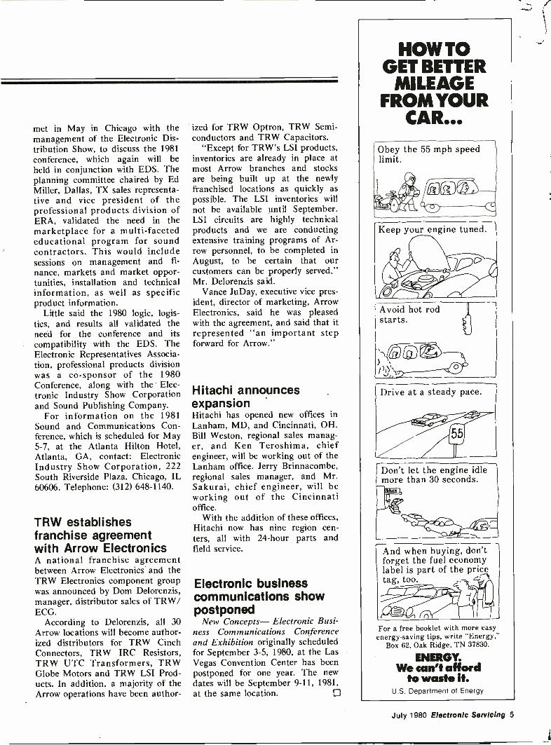
Obey the 55 mph speedlimit.
Qt.. ga-Daf4-7-461 w411Keep your engine tuned.
Avoid hot rodstarts.
1
EZ.44'
Drive at a steady pace.
Don't let the engine idlemore than 30 seconds.
And when buying, don'tforget the fuel economylabel is part of the pricetag, too.
41110Fisti
.0011For a free booklet with more easy
energy -saving tips, write "Energy,"Box 62, Oak Ridge, TN 37830.
ENERGY.We can't afford
to waste it.U.S. Department of Energy
July 1980 Electronic Servicing 5
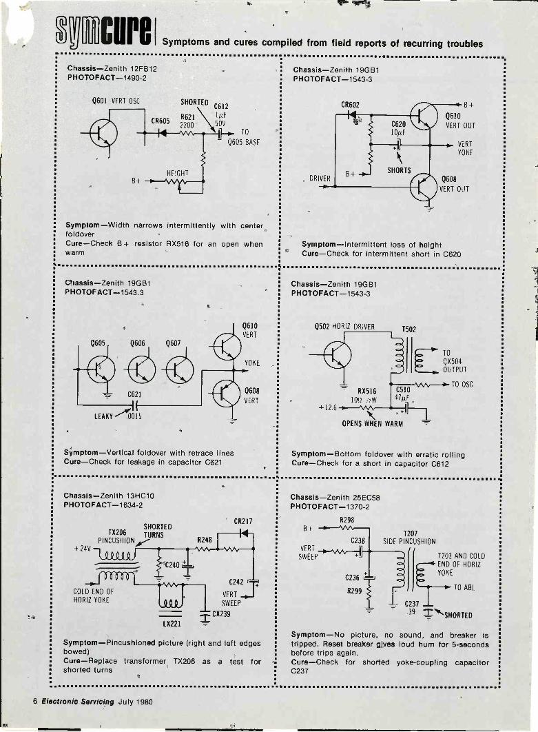
cure Symptoms and cures compiled from field reports of recurring troubles
Chassis-Zenith 12FB12PHOTOFACT-1490-2
Q601 VERT OSC
CR6052200
HEIGHT
SHORTEDC612
R621 1050V
TO
Q605 BASE
Symptom-Width narrows intermittently with centerfoldoverCure-Check B + resistor RX516 for an open whenwarm
Chassis-Zenith 19GB1PHOTOFACT-1543.3
Q605 Q606 Q607
C621
LEAKY -"0015
Symptom-Vertical foldover with retrace linesCure-Check for leakage in capacitor C621
Q610
VERT
YOKE
Q608
VERT
Chassis-Zenith 13HC10PHOTOFACT-1634-2
SHORTED
PINCUSHIONTX206
TURNS
+ 24V
C24014±,
C242
COLD END OFHORIZ YOKE
R248
CR217
14
VERT
.191, SWEEP
:"±-CX239
LX221
Symptom-Pincushioned picture (right and left edgesbowed)Cure-Replace transformer TX206 as a test forshorted turns
ti
Chassis-Zenith 19GB1PHOTOFACT-1543-3
CR602 13 4-
Q610
VERT OUT
VERT
YOKE
Q608
VERT OUT
Symptom-Intermittent loss of heightCure-Check for intermittent short in C620
ti
Chassis-Zenith 19GB1PHOTOFACT-1543-3
Q502 HORIZ DRIVER
126
RX516
10(.!
1502
C51047/tF
+1
OPENS WHEN WARM
TO
QX504
OUTPUT
TO OSC
Symptom-Bottom foldover with erratic rollingCure-Check for a short in capacitor C612
Chassis-Zenith 25EC58PHOTOFACT-1370-2
B+R298
C238VERT 7"
SWEEP
C236 1+
R299
T207SIDE PINCUSHION
11
T203 AND COLDEND OF HORIZYOKE
TO ABL
C237 1.
39 T --..`SHORTED
Symptom-No picture, no sound, and breaker istripped. Reset breaker gives loud hum for 5 -secondsbefore trips again.Cure-Check for shorted yoke -coupling capacitorC237
6 Electronic Servicing July 1980
eTh
Mike newsJohn G. Myers has been named program manager,
pressure sensor products, for Micro Switch. Myerswas director of the Office of Technology Assessmentat the Honeywell Corporate Technology Center inMinneapolis, MN.
Joe Grandolfo has been appointed assistant control-ler of Quasar. Grandolfo also retains his previous titleand responsibilities as manager of accounting andbudgets.
Steven T. Klein has,been promoted to regional salesmanager, Central region, for Klein Tools. Klein wasformerly marketing research manager.
Also at Klein Tools, James A. Mallek has beennamed marketing services manager. He was formerlycustomer service manager.
Robert N. Noyce, vice chairman of Intel Corpora-tion, has been elected to membership in the NationalAcademy of Sciences. Noyce, a semiconductorphysicist and businessman, is co -inventor of theintegrated circuit and a pioneer of the Bay Area'ssemiconductor industry, which is based largely onintegrated circuit technology.
Noyce is one of 59 scientists and engineers electedto the Academy at its 117th annual meeting. Of these,three others are from industry: Richard G. Brewer,IBM Fello, IBM Research Laboratory, San Jose;William L. Brown, president, Pioneer Hi -Bred Interna-tional, Des Moines, IA; and Theodore H. Maiman,inventor of the laser, vice president, TRW Electronics,Los Angeles, CA.
Fred E. Scott, Jr. has joined Hitachi as director ofVTR engineering. Before joining Hitachi, Scott wassenior engineer, 1 -inch VTR for Sony Broadcast.
Dennis W. Carroll has been appointed nationalsales manager of A. W. Sperry Instruments. Formerly,he was assistant sales manager.
Altec Lansing has announced the appointment ofthree district managers to its professional productsdivision: Gabriella Engebretson, Southwest region; BillSparling, Northwest region; and Jack Arndt, Southeastregion.
James 0. Lawson has been appointed engineeringmanager for the Sylvania connector products opera-tion. He succeeds W. L. Griffin, who has resigned.
Milton A. "Mac" Clement, of Stromberg-Carlson,has been named chairman of EIA's TR 41.1 PABXEngineering Standards Committee. He replaces 0. J.Gusella of GTE Service Corporation, who continues aschairman of the parent TR-41 Voice TelephoneTerminals Committee.
Shure Brothers has appointed Robert L. Laytoninternational sales manager.
Patrick R. Wilson has been named to the newposition of director of public affairs, GTE entertain-ment products group. Wilson was manager of publicaffairs. 0
The one toolthat pays for itself
first t e out.
Slip this SymptomRepair Manual into yourtool caddy. It lists all sorts of symptoms forindividual GE TV chassis and tells youwhat to check and in what order. You cansave hours of frustrating (and unprofitable)diagnostic time.
The new Sixth Edition manualthe combined experience of hundreds ofservice technicians into a 51/2" by 81/2; 104page package. It's free to subscribers of GETechnical Data, but non -subscribingtechnicians may obtain a copy by paying a$2.00 handling fee. You can make that backin the first few minutes it saves.
17DUTCH" MEYERGENERAL ELEC. I RIC COMPANYPORTSMOUTH,VA 23704Please check items desired:
0 One Symptom Repair Manual ($2.00 Enclosed)0 Two Symptom Repair Manuals ($3.00 Enclosed)
Enclosed is 0 Check 0 Cash or0 Money Order (No C.O.D. Please)
ES
Name
Service Company
Address
L-.,City State Zip
IT'S OUR BUSINESS TO MAKE YOUR BUSINESS EASIER.
GENERAL ELECTRIC
July 1980 Electronic Servicing 7
By James E. KlugeTechnical EditorWinegard Company
ConsumerServicing Tips forinsteilling TV
antennasAntenna installations are seldom identical. Therefore, it is not possible to list and describe allsteps. These tips show things to do and not to do during installations. Better TV reception, longerantenna lifespan and satisfied customers are some of the benefits.
Many present-day installations ofoutside antennas are replacementsfor previous systems. Each customerwill make comparisons between theperformance and lifespan of the oldsystem versus the new one. Thisadds a strong additional reason tothe installer's normal desire to dothe best possible job. The newantenna must improve the picture.
Before installing a new antenna,a technician should observe thequality of picture on all channels ofthe television. A new antennacannot correct erratic receptionfrom corroded contacts in the TVtuner. Also, a television in perfectoperating condition cannot providea good picture from a defective orinferior antenna system. The cus-
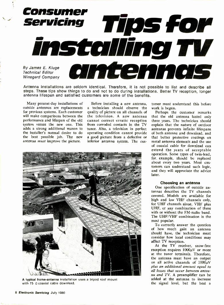
A typical home -antenna installation uses a tripod roof mountwith 75 Q coaxial cable downlead.
tomer must understand this beforework is begun.
Perhaps the customer remarksthat the old antenna lasted onlythree years. The technician shouldexplain that the nature of outdoorantennas prevents infinite lifespansof both antenna and downlead, andthat better protective coatings onmetal antenna elements and the useof coaxial cable for downlead canextend the years of acceptableoperation. Some types of twin -lead,for_ example, should be replacedabout every two years. Most cus-tomers can understand such logic,and they will appreciate the advicelater.
Choosing an antennaOne specification of outside an-
tennas describes the TV channelscovered. Models are available forhigh and low VHF channels only,for UHF channels alone, VHF plusUHF, or any combination of thesewith or without the FM -radio band.The UHF/VHF combination is themost popular.
To correctly answer the questionof how much gain an antennashould have, the technician mustconsider how local conditions mayaffect TV reception.
At the TV receiver, snow -freereception requires 10000/ or moreat the tuner terminals. Therefore,the antenna must have an outputon all active channels of 1000µVplus an additional amount equal toall losses that occur between anten-na and TV. A preamplifier tan beadded at the antenna to increasethe signal level, but the best a
8 Electronic Servicing July 1980
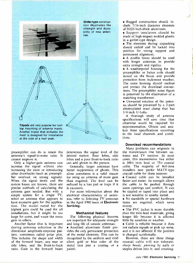
Girder -type construc-tion illustrates thestrength and dura-bility of new anten-nas.
Tripods are very popular for roof-top mounting of antenna masts.Another tripod that includes themast is designed for installationat the side of a roof peak.
preamplifier can do is retain theantenna's signal-to-noise ratio. Itcannot improve it.
Only a higher -gain antenna canincrease the signal without alsoincreasing the snow or introducingother drawbacks (such as preampli-fier overload on strong signals).When the signal levels and thesystem losses are known, there areprecise methods of calculating theantenna gain needed. But with asimple system for a single TV,select an antenna that appears tohave excessive gain for the applica-tion. The model rated for thehighest gain could be used for allinstallations, but it might be toolarge for some, and waste the extragain in others.
Another factor that is importantduring antenna selection is thedirectional amplitude -response pat-tern, sometimes called polar plot.This includes the shape and widthof the forward beam, any rear orside lobes, and the front -to -backratio. Gain in the forward beam
determines the signal level of thedesired station. Rear lobes, sidelobes and a poor front -to -back ratiocan add ghosts to the picture.
Generally, larger antennas havebetter suppression of ghosts. Thisalone sometimes is a valid reasonfor using an antenna of more gainthan required. The level can bereduced by a loss pad or traps if itis excessive.
For more information about theelectrical characteristics of anten-nas, refer to Selecting TV antennasin the April 1980 issue of ElectronicServicing.
Mechanical featuresThe following physical features
are important for adequate strengthand long life of outside antennas: Anodized aluminum finish pro-vides the only permanent protectionof the metal elements. This can berecognized by the uniform and vividsilver, gold or blue color of themetal (not just a coating or apaint).
Rugged construction should in-clude 7/16 -inch diameter elementsof 0.025 -inch -thick aluminum. Support insulators should bemade of high -impact molded plasticin a girder -type design. The elements during unpackingshould unfold and be locked intoposition for strong support andpermanent alignment. A double boom should be usedwith longer antennas to provideextra strength and rigidity. A weatherproof housing for thepreamplifier or balun coils shouldmount on the boom and provideprotection from inclement weather.The same housing should encloseand protect the downlead connec-tions. The preamplifier noise figureis preserved by the elimination of amatching transformer. Unwanted rotation of the anten-na should be prevented by a 2 -partelectroplated mast clamp that has1/4 -inch U -bolts.
A thorough study of antennaspecifications will save time thatotherwise would be required forexperimentation. Obtain and ana-lyze these specifications accordingto the local channels and condi-tions.
Downlead recommendationsMany problems can originate in
the transmission line between an-tenna and TV receiver. In mostcases, this transmission line eitheris 300Q twin lead or 75Q coaxialcable. The majority of full-timeinstallers now prefer MATV-typecoaxial cable for these reasons: Coaxial cable can be installedfaster and easier. Its strength allowsthe cable to be pushed throughsome openings and conduit. It canbe stapled or taped into place andis not sensitive to nearby metal. No standoffs or special hardwareitems are required, which savesmoney. The PVC jacket is more durablethan the twin -lead materials, givinglonger life because it is affectedlittle by sunshine or weather. Cable is reliable because it doesnot radiate signals or pick up noise,and it is not affected if the positionis changed accidentally.
However, there are three thingscoaxial cable will not tolerate:sharp bends; piercing by nails orstaples driven into it; and crushing.
July 1980 Electronic Servicing 11
Antenna installations
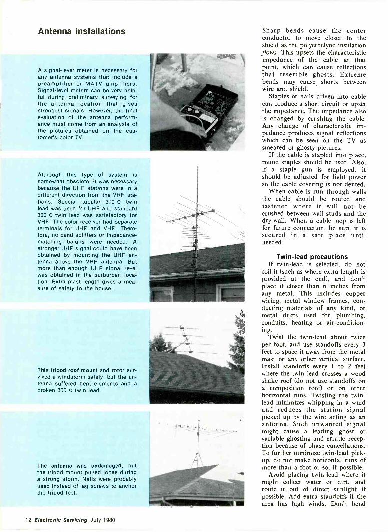
A signal -lever meter is necessary foiany antenna systems that include apreamplifier or MATV amplifiers.Signal -level meters can be very help-ful during preliminary surveying forthe antenna location that givesstrongest signals. However, the finalevaluation of the antenna perform-ance must come from an analysis ofthe pictures obtained on the cus-tomer's color TV.
Although this type of system issomewhat obsolete, it was necessarybecause the UHF stations were in adifferent direction from the VHF sta-tions. Special tubular 300 S2 twinlead was used for UHF and standard300 S2 twin lead was satisfactory forVHF. The color receiver had separateterminals for UHF and VHF. There-fore, no band splitters or impedance -matching baluns were needed. Astronger UHF signal could have beenobtained by mounting the UHF an-tenna above the VHF antenna. Butmore than enough UHF signal levelwas obtained in the surburban loca-tion. Extra mast length gives a mea-sure of safety to the house.
This tripod roof mount and rotor sur-vived a windstorm safely, but the an-tenna suffered bent elements and abroken 300 Q twin lead.
The antenna was undamaged, butthe tripod mount pulled loose duringa strong storm. Nails were probablyused instead of lag screws to anchorthe tripod feet.
Sharp bends cause the centerconductor to move closer to theshield as the polyethelyne insulationflows. This upsets the characteristicimpedance of the cable at thatpoint, which can cause reflectionsthat resemble ghosts. Extremebends may cause shorts betweenwire and shield.
Staples or nails driven into cablecan produce a short circuit or upsetthe impedance. The impedance alsois changed by crushing the cable.Any change of characteristic im-pedance produces signal reflectionswhich can be seen on the TV assmeared or ghosty pictures.
If the cable is stapled into place,round staples should be used. Also,if a staple gun is employed, itshould be adjusted for light powerso the cable covering is not dented.
When cable is run through wallsthe cable should be routed andfastened where it will not becrushed between wall studs and thedry -wall. When a cable loop is leftfor future connection, be sure it issecured in a safe place untilneeded.
Twin -lead precautionsIf twin -lead is selected, do not
coil it (such as where extra length isprovided at the end), and don'tplace it closer than 6 inches fromany metal. This includes copperwiring, metal window frames, con-ducting materials of any kind, ormetal ducts used for plumbing,conduits, heating or air-condition-ing.
Twist the twin -lead about twiceper foot, and use standoffs every 3feet to space it away from the metalmast or any other vertical surface.Install standoffs every 1 to 2 feetwhere the twin lead crosses a woodshake roof (do not use standoffs ona composition roof) or on otherhorizontal runs. Twisting the twin -lead minimizes whipping in a windand reduces the station signalpicked up by the wire acting as anantenna. Such unwanted signalmight cause a leading ghost orvariable ghosting and erratic recep-tion because of phase cancellations.To further minimize twin -lead pick-up, do not make horizontal runs ofmore than a foot or so, if possible.
Avoid placing twin -lead where itmight collect water or dirt, androute it out of direct sunlight ifpossible. Add extra standoffs if thearea has high winds. Don't bend
12 Electronic Servicing July 1980
twin -lead too sharply. And don'tuse nails, tacks or staples throughthe twin -lead to secure it. Anelectrical field exists between (andin the vicinity of) the two conduc-tors. Therefore, any conductor be-tween or near the two wires oftwin -lead distorts the electricalfield, and this can smear thepicture or cause ghost -like reflec-tions.
Twin -lead is made of clear orbrown polyethylene that can collectdirt, carbon and corrosion on thesurface. Moisture from dew, rain orsnow can change the twin -leadcorrosion into a conductor thatdistorts the characteristic impe-dance, reduces the signal level, andunbalances the line.
Some people believe that thepropagation of TV signals is af-fected by wet weather. Althoughthere is a slight change, it is far lessthan the performance degradationbrought by the change of twin -leadwhen wet. This susceptibility toweather is one reason why sometwin -lead should be replaced everytwo years.
It should be clear that coaxial
cable is often preferred over twin -lead because it is easier andcheaper to install and has betterreliability in unfavorable weather.Twin -lead is available with an extraprotective jacket. Some types havebraided shield around it. These areimprovements, but then the costalmost equals coaxial cable.
Installing the antennaDon't decide the antenna loca-
tion until the performance is evalu-ated at all roof areas. Mount theantenna on a 5- or 10 -foot mast,attach downlead to it and to asignal -level meter or a TV receiver,and walk around the roof todetermine the spot with thestrongest and clearest signal.
However, the final decisionshould not be made until thepicture quality on all active chan-nels is examined carefully on theTV screen. This shows anotheradvantage of coaxial cable: It canbe laid carelessly across the roof,down to the ground, and into thehouse through any door or windowduring the walk -the -roof test with-out degrading the signal quality.
The picture quality will not changewhen the antenna is installed andthe cable is fastened permanently.Unlike twin -lead, the length of coaxis not critical, and the excess canbe coiled if desired without degrad-ing the picture.
After the best location is found,the antenna should be mountedsecurely by chimney mount, atripod at the roof peak, or on anoutside wall near a peak. A stronglymounted tripod will safely sustainan antenna with 5- to 10 -feet ofmast. Of course, smaller mountscan be used if adequate guy wiresare attached properly to the mast.
Antenna elements should be ex-tended and locked into place andthe downlead and/or preamplifiershould be attached before theantenna assembly is mounted to themast. If standoffs are used, theyshould be mounted before the mastwith antenna is secured to themounting device.
If possible, don't penetrate com-position roof shingles with nails, lagscrews or standoffs. Seal the roofingcarefully if penetration is necessary.For example, both the bottoms and
Continued on page 17
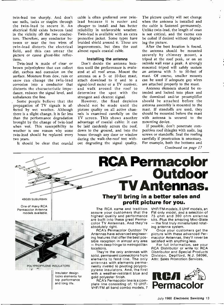
4BG20 SUBURBAN
One of many RCAPermacolor Antenna
models available.
POLYPROPYLENE INSULATORS
Insulator designlocks elements fortop performanceand long life.
RCA PermacolorOutdoor
TV Antennas.They'll bring in a better sales and
profit picture for you.The RCA name and tradition
assure your customers that thehighest quality and performanceare built into these great Perma-color TV Antennas. And they'reabsolutely right.
RCA's Permacolor Outdoor TVAntennas have advanced engineer-ing features that offer the best pos-sible reception in almost any area- from deep fringe to metropolitanlocations.
They're the only antennas withsolid, permanent connections fromelements to feed line. The onlyantennas with elements perma-nently riveted to pivoting polypro-pylene insulators. And, the firstwith a weather -resistant blue andgold polyester finish.
RCA's Permacolor line is a com-plete line consisting of: 10 UHF-VHF/FM all band combo models, 7
VHF/FM models, 5 UHF models, anFM only model, and a selection of75 ohm and 300 ohm antennakits. Plus the amazing Mini -State- the first truly miniaturized rotat-ing antenna system.
Once your customers get thepicture with these advanced Per-macolor Antennas, they'll never besatisfied with anything less.
For full information, see yourRCA Distributor or write to: RCADistributor and Special ProductsDivision, Deptford, N.J. 08096,Attn: Sales Promotion Services.
RCAPermacolor
July 1980 Electronic Servicing 13
Consumer Servicing
AntennaMODEL
FEATURES HIGH PERFORMANCE
UHF CORNER REFLECTOR EXCELLENT F/8 RATIO RUGGED MECHANICAL DESIGN COMPLETE WITH BEHIND THE
SET SIGNAL SPLITTERS
GOLD CORODIZED
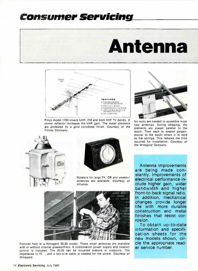
Finco model 1780 covers UHF, FM and both VHF TV bands. Acorner reflector increases the UHF gain. The metal elementsare protected by a gold corodized finish. Courtesy ofFinney Company.
the
Rotators for large TV, CB and amateurantennas are available. Courtesy ofAlliance.
Pictured here is a Winegard 20-20 model. These small antennas are availablewith or without internal preamplifiers. A combination power supply and rotationcontrol is included. The 20-20 can be mounted indoors or outdoors. Theimpedance is 75 , and a two -wire cable is needed for the power. Courtesy ofWinegard.
0:4No tools are needed to assemble mostnew antennas. During shipping, theelements are placed parallel to theboom. Then each is rotated perpen-dicular to the boom where it is heldby flat springs. This reduces the timerequired for installation. Courtesy ofthe Winegard Company.
Antenna improvementsare being made con-stantly. Improvements ofelectrical performance in-clude higher gain, widerbandwidth and higherfront -to -back signal ratio.In addition, mechanicalchanges provide longerlife with more durableconstruction and metalfinishes that resist cor-rosion.
To obtain up-to-dateinformation and specifi-cation sheets for thenew models shown, cir-cle the appropriate read-er service number.
14 Electronic Servicing July 1980
roundup
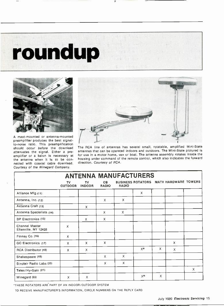
A mast -mounted or antenna -mountedpreamplifier produces the best signal-to-noise ratio. This preamplificationshould occur before the downleadattenuates the signal. Either a pre-amplifier or a balun is necessary atthe antenna when it is to be con-nected with coaxial cable downlead.Courtesy of the Winegard Company.
"allippr2
11
4
The RCA line of antennas has several small, rotatable, amplified Mini -Stateantennas that can be operated indoors and outdoors. The Mini -State pictured isfor use in a motor home, van or boat. The antenna assembly rotates inside thehousing under command of the remote control, which also indicates the forwarddirection. Courtesy of RCA.
ANTENNA MANUFACTURERSTV TV CB BUSINESS ROTATORS MATV HARDWARE TOWERS
OUTDOOR INDOOR RADIO RADIO
Alliance Mfg.(11) X
Antenna, Inc. (12) X X
Antenna Craft (13) X
Antenna Specialists (14) X X
BP Electronics (15) X X
Channel MasterEllenville, NY 12428
X
Finney Co. (16) X
GC Electronics (17) X X X X
RCA Distributor (18) X X X* X X
Shakespeare (19) X X
Sinclair Radio Labs (20) X X
Telex/Hy-Gain (21) X
Winegard (22) X X X* X
'THESE ROTATORS ARE PART OF AN INDOOR/OUTDOOR SYSTEM
TO RECEIVE MANUFACTURER'S INFORMATION, CIRCLE NUMBERS ON THE REPLY CARD
July 1980 Electronic Servicing 15
Antenna Roundup
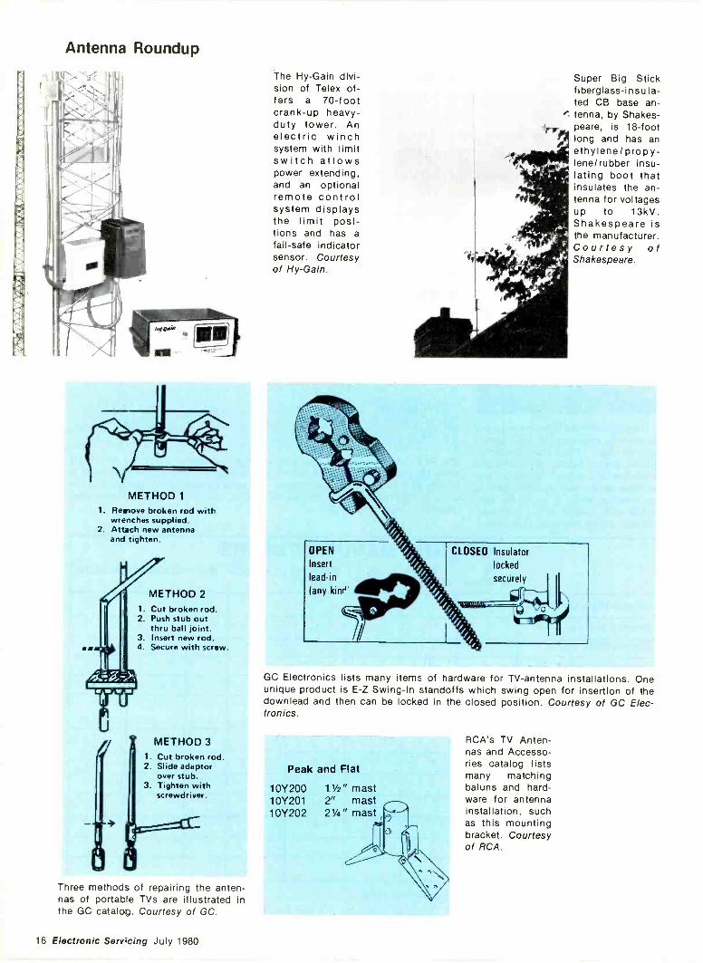
METHOD 11. Remove broken rod with
wrenches supplied.2. Attach new antenna
and tighten.
METHOD 21. Cut broken rod.2. Push stub out
thru ball joint.3. Insert new rod.4. Secure with screw.
METHOD 31. Cut broken rod.2. Slide adaptor
over stub.3. Tighten with
screwdriver.
Three methods of repairing the anten-nas of portable TVs are illustrated inthe GC catalog. Courtesy of GC.
The Hy -Gain divi-sion of Telex of-fers a 70 -footcrank -up heavy-duty tower. Anelectric winchsystem with limitswitch allowspower extending,and an optionalremote controlsystem displaysthe limit posi-tions and has afail-safe indicatorsensor. Courtesyof Hy -Gain.
Super Big Stickfiberglass -insula-ted CB base an-
" tenna, by Shakes-peare, is 18 -footlong and has anethylene/propy-lene/rubber insu-lating boot thatinsulates the an-tenna for voltagesup to 13kV.Shakespeare isthe manufacturer.Courtesy ofShakespeare.
OPEN
Insert
lead-in
(any kinru
CLOSED Insulator
locked
securely
GC Electronics lists many items of hardware for TV -antenna installations. Oneunique product is E -Z Swing -In standoffs which swing open for insertion of thedownlead and then can be locked in the closed position. Courtesy of GC Elec-tronics.
Peak and Flat
10Y200 11/2" mast10Y201 2" mast10Y202 21/4" mast
RCA's TV Anten-nas and Accesso-ries catalog listsmany matchingbaluns and hard-ware for antennainstallation, suchas this mountingbracket. Courtesyof RCA.
16 Electronic Servicing July 1980
Antenna installationsContinued from page 13tops of tripod feet should be sealed,including the screw heads. Lagscrews should be installed (insteadof nails) in tripod feet. In areaswhere strong wind gusts sometimesoccur, the tripod feet should bepositioned over the roof -supportbeams, and the lag bolts screwedtightly into these beams.
Signal levelsIf signal -level tests show less than
1000µV at the television for eachpicture carrier, there are threechoices for improvement. The an-tenna can be moved to a differentor higher location. A larger antennawith more gain can be substituted,or a low -noise preamplifier can beadded to the antenna. (Otherremedies, such as vertical or hori-zontal stacking of multiple identicalantennas, sometimes are necessaryin specific locations.)
Remember that the visible snow(signal-to-noise ratio) can never bebetter than it is at the antenna. Allother parts of the system eitherretain the S/N ratio or make itworse. A good preamplifier canovercome the downlead losses thatfollow, and thus maintain theapproximate S/N ratio coming fromthe antenna. No other amplificationcan reduce the snow.
Importance of matchingAll antennas, transmission lines
and TV tuner signal -inputs havecharacteristic impedances. If thesethree have identical impedances, nomatching is needed. Usually, how-ever, matching is required. Mis-matching produces smeared pic-tures, ghosts and possibly snowfrom insufficient signal.
Most antennas now have 750balanced impedances. To match acoaxial cable, a 750 balanced to750 unbalanced matching trans-former is required. These trans-formers are called baluns frombalanced to unbalanced. For foldeddipoles having 3000 balanced im-pedance, a 4 -to -l -ratio balun isnecessary to match 750 unbalancedcoaxial cable.
The usual input impedance of aTV tuner is 750 unbalanced. Oldertelevisions included a 4 -to -l -ratiobalun that matched the common300 0 balanced twin -lead to thetuner. Now the trend is towardsupplying a 75o connector that
connects directly to the tuner input.(Of course, hot chassis, televisionsmust have series capacitors forsafety.) Therefore, coaxial cablefrom MATV or CATV system canbe connected without a balun.
Unfortunately, many 3000 trans-mission -line systems still are in use.Indoor dipole (rabbit ear) antennasare one example. Consequently,most TV manufacturers provideboth 750 unbalanced and 3000balanced inputs that can be se-lected by switches or by properconnections of wires and lugs.
When 750 cable connects directlyto the TV -tuner 750 input, the onlybalun is between antenna andcable. Elimination of unnecessarybaluns minimizes signal losses andimpedance mismatches, sincebaluns are not perfect devices.
ProtectionBecause of the location and
materials, outside antennas andmetal masts function as a type oflightning rod, giving some protec-tion when grounded. Of course,nothing can protect totally againsta direct strike of lightning, andmore than an antenna would bedestroyed in that case. However,partial protection is provided by agrounded mastgradual buildup of static charges. Italso grounds the energy induced bynearby lightning strikes.
Use number 6 AWG aluminumor number 8 AWG copper wire toconnect the mast to a metal stakedriven several feet into dampground. The stake should have adiameter between 1/2 -inch and5/8 -inch. Connections at both endsof the ground wire should be tightand of heavy-duty materials.
Don't clamp the antenna at theextreme top of the mast. Instead,mount it about 1 foot below themast top so any minor electricaldischarges can strike the mastdirectly instead of the antenna.
Finally, check the entire installa-tion for secure mounting of thedownlead, correct impedancematching, tight connections at theTV receiver, and the performanceof the television on all activechannels.
No two antenna installations areidentical. Therefore, it is difficult tosuggest precise step-by-step proce-dures. These general tips shouldprevent most serious mistakes whileproviding the best possible recep-tion.
APPLIANCEREPAIRBOOKS
Thirteen Handbooks written in easy -to -under-stand language by experts in the service fieldwith illustrations and diagrams! Acclaimed byinstructors and professionals alike! How todiagnose and repair air conditioners, refrigera-tors, washers, dryers, ranges, microwaveovens, dishwashers, vacuum cleaners, electro-static air cleaners, RV gas appliances, hairdryers, motors, water heaters, coffeemakers,can openers, floor polishers, steam irons, foodmixers, lawn care appliances, electric knives,electric and digital clocks and many others.Also fundamentals of said state, setting up ashop, using test instruments and more Only$2.65 to $4.90 ea.
SEND FOR FREE PRICE LIST
Gamit, Dept. ES110 W. St. Charles Road,Lombard, Illinois 60148Circle (5) on Reply Card
NATESA
5908 S.
Troy
Chicago
IL 60629
ARE YOU A PRO?...the not for profit associationchampioning independents' right tocompete, and delivering valuablebenefits continuously since 1950.
LEADING SPOKESMAN
TRADE INFORMATIONDISPENSER
WATCHDOG LOBBYIST
YARDSTICK OF STANDARDS CONSUMER RELATIONS
COUNSELOR PROBLEM SOLVER
We are not freeloaders. So our checkfor $60.00 dues is attached. As ourspecial premium, please ship the in-dicated $15.00 Manual.
Practical Business Manual- OR
Service Contract Manual
Circle (6) on Reply Card
July 1980 Electronic Servicing 17
Consumer Servicing
ACCproblems
intube TVs
PART 2By Homer L. Davidson and Carl Babcoke
Additional AGC troubleshooting methods for older TVs areexplained. Case histories illustrate practical servicing.
The diagnosis of AGC problemsin tube -type color receivers shouldbe divided into two parts. Includedin the first simple tests are thesesteps: observation of reception onall active channels, and of the snowon one channel that does not havea signal; exploratory adjustments ofthe AGC control; tube testing; andtemporary use of a test tuner. Onlya short time should be devoted tothese, first tests. They often arevaluable, but not sufficiently com-plete to serve as the only testingtechniques.
After the short-cut tests havefailed to locate the AGC defect, themore logical methods (analysis ofwaveforms, resistances, and dc volt-ages) should be started immedi-ately.
In the case histories that follow,these troubleshooting principles areapplied to several typical AGCfailures.
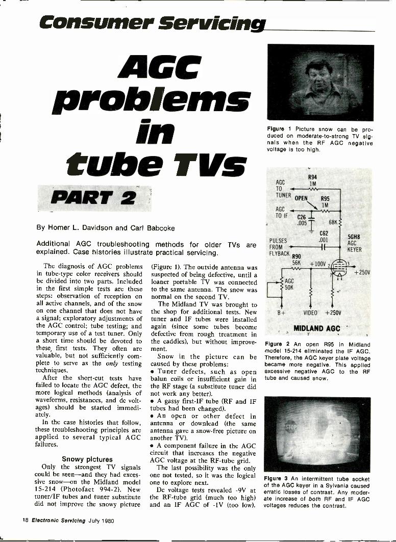
Snowy picturesOnly the strongest TV signals
could be seen-and they had exces-sive snow-on the Midland model15-214 (Photofact 994-2). Newtuner/IF tubes and tuner substitutedid not improve the snowy picture
(Figure 1). The outside antenna wassuspected of being defective, until aloaner portable TV was connectedto the same antenna. The snow wasnormal on the second TV.
The Midland TV was brought tothe shop for additional tests. Newtuner and IF tubes were installedagain (since some tubes becomedefective from rough treatment inthe caddies), but without improve-ment.
Snow in the picture can becaused by these problems: Tuner defects, such as openbalun coils or insufficient gain inthe RF stage (a substitute tuner didnot work any better). A gassy first -IF tube (RF and IFtubes had been changed). An open or other defect inantenna or downlead (the sameantenna gave a snow -free picture onanother TV). A component failure in the AGCcircuit that increases the negativeAGC voltage at the RF-tube grid.
The last possibility was the onlyone not tested, so it was the logicalone to explore next.
Dc voltage tests revealed -9V atthe RF-tube grid (much too high)and an IF AGC of -1V (too low).
Figure 1 Picture snow can be pro-duced on moderate -to -strong TV sig-nals when the RF AGC negativevoltage is too high.
AGC
TO
TUNER
R94
AGC
TO IF
PULSES
FROM
FLYBACKR9056K
AGC
50K
1M
OPEN R95
1M
C26.005 T. 68K
- C62
.001
+100V 2
VIDEO +250V
MIDLAND AGC
5GH8
AGC
KEYER
+250V
Figure 2 An open R95 in Midlandmodel 15-214 eliminated the IF AGC.Therefore, the AGC keyer plate voltagebecame more negative. This appliedexcessive negative AGC to the RFtube and caused snow.
Figureof the AGC keyer in a Sylvania causederratic losses of contrast. Any moder-ate increase of both RF and IF AGCvoltages reduces the contrast.
3 An intermittent tube socket
18 Electronic Servicing July 1980
Logic pointed to a defect in the IFAGC circuit. Insufficient AGC volt-age to the IF tube forces the AGCkeyer to supply too much negativeAGC to the RF tube, and theresulting zero gain of the RF tubeallows the normal mixer noise(snow) to seem more prominent.
Ohmmeter measurements of theAGC circuit (Figure 2) proved thatR95 was open, and a new onestopped the abnormal snow. Thisrepair required only a minimumtime, since the symptoms andpreliminary diagnosis identified theprobable defect.
Intermittent contrastThe Sylvania D06-3 occasionally
would lose contrast (Figure 3).During these times-which werenot related to elapsed time orchassis heat-the AGC control ad-justments had no effect on thepicture. Connection of a substitutetuner didn't affect the intermittentcondition.
Horizontal pulses at pin 1 of the6GH8 AGC-keyer tube were nor-mal, but the video at grid pin 9 wasweak. Insufficient video at pin 9 isnot likely to be the only problem,since this would force the AGCkeyer to increase the RF and IFgain, thus raising the video level tothe required point. Therefore, thepreliminary diagnosis was changedfrom AGC problem to video prob-lem.
When a scope probe was touchedto the pin -6 plate of first -videoamplifier 6MB8, the picture sud-denly regained its contrast. Movingand twisting the componentsaround the socket proved the socketwas intermittent. Installation of anew 6MB8 socket solved the inter-mittent contrast.
Either video defects or excessiveAGC gain -reduction can reduce thecontrast. The test methods must beable to identify the one cause.
Multiple problemsThree separate troubles were
found in one RCA CTC31A chassis.It is common for older color re-ceivers to have more than one prob-lem, since customers often waituntil the TV fails completely beforehaving these secondary defects re-paired.
HORIZ PULSESFROM
DAMPER
CATHODER79
AGC 1.2M
TO
TUNERR82
AGC 330K
TO
IF
C90
68pF680V PP
VIDEO
C55
180pF
R8033K
C53
R84 .18 -r120K ÷
(-90V)+8V
R816GH8A
220KY8A AGC KEYER VIDEO
R85I2M
R8627K
INCREASED
RESISTANCE
R89
R9AGC
50K
RCA CTC31A AGC
18K
R91
39K+220V
3
+75V
R871
C2B500
RU18K
+160V
R901800
+225V
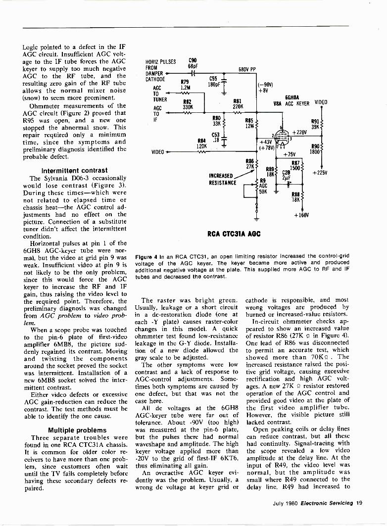
Figure 4 In an RCA CTC31, an open limiting resistor increased the control -gridvoltage of the AGC keyer. The keyer became more active and producedadditional negative voltage at the plate. This supplied more AGC to RF and IFtubes and decreased the contrast.
The raster was bright green.Usually, leakage or a short circuitin a dc -restoration diode (one ateach -Y plate) causes raster -colorchanges in this model. A quickohmmeter test found low -resistanceleakage in the G -Y diode. Installa-tion of a new diode allowed thegray scale to be adjusted.
The other symptoms were lowcontrast and a lack of response toAGC-control adjustments. Some-times both symptoms are caused byone defect, but that was not thecase here.
All dc voltages at the 6GH8AGC-keyer tube were far out oftolerance. About -90V (too high)was measured at the pin -6 plate,but the pulses there had normalwaveshape and amplitude. The highkeyer voltage applied more than-20V to the grid of first -IF 6KT6,thus eliminating all gain.
An overactive AGC keyer evi-dently was the problem. Usually, awrong dc voltage at keyer grid or
cathode is responsible, and mostwrong voltages are produced byburned or increased -value resistors.
In -circuit ohmmeter checks ap-peared to show an increased valueof resistor R86 (27K n in Figure 4).One lead of R86 was disconnectedto permit an accurate test, whichshowed more than 70K0 . Theincreased resistance raised the posi-tive grid voltage, causing excessiverectification and high AGC volt-ages. A new 27K s7 resistor restoredoperation of the AGC control andprovided good video at the plate ofthe first video amplifier tube.However, the visible picture stilllacked contrast.
Open peaking coils or delay linescan reduce contrast, but all thesehad continuity. Signal -tracing withthe scope revealed a low videoamplitude at the delay line. At theinput of R49, the video level wasnormal, but the amplitude wassmall where R49 connected to thedelay line. R49 had increased to
July 1980 Electronic Servicing 19
AGC problems
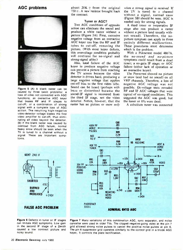
Figure 5 (A) A blank raster can becaused by three basic problems: aloss of video not connected with AGCfunctions; an overactive AGC keyerthat biases RF and IF stages tocut-off; or a combination of strongsignal with a complete loss of AGCaction. The resulting high -negativevideo -detector voltage biases the firstvideo amplifier to cut-off, thus elimi-nating all video beyond the detector.(B) If the blank raster was caused byoverload from AGC failure, normalheavy snow should be seen when theTV is tuned to a channel without asignal. These are important symp-toms.
6EH7 2ND IF
SHORTED
470
ANDBURNED
INCREASED +240V
FALSE AGC PROBLEM
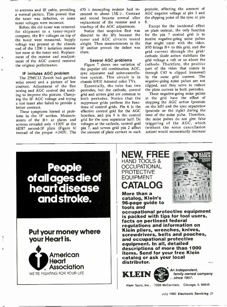
Figure 6 Defects in tuner or IF stagescan imitate AGC symptoms. Low gainin the second IF stage of a Zenithcaused a low contrast picture andnoisy sound.
about 20K Q from the original750 Q . A new -resistor brought backthe contrast.
Tuner or AGC?Two AGC conditions of opposite
action can eliminate the sound andproduce a white raster without apicture (Figure SA). First, excessivenegative voltage from an overactiveAGC keyer can bias the RF and IFtubes to cut-off, removing thepicture. (With most keyer defects,this overvoltage condition probablywill continue for no -signal andstrong -signal alike.)
Also, total failure of the AGCkeyer to produce negative voltagecan prevent a picture from reachingthe TV screen because the videodetector is driven hard, producing alarge negative voltage that appliescut-off bias to the first video tube.Sound can be heard (perhaps withbuzz or distortion) because thesound -IF signal is recovered fromthe third IF stage, not the videodetector. Notice, however, that theraster has no picture or snow only
when a strong signal is received. Ifthe TV is tuned to a channelwithout a signal, normal snow(Figure 5B) should be seen. AGC isneeded only for strong signals.
A dead tuner or inoperative IFstage also can produce a rasterwithout a picture (and usually with-out sound). Therefore, the no -picture symptom can apply to threeentirely different malfunctions.These procedures must determinewhich is the problem.
With a Penncrest model 4867A,the no -sound and no -picturesymptoms could result from a deadtuner; a no -gain IF stage; or AGCfailure (either lack of operation oran overactive keyer).
The Penncrest showed no pictureor snow (and had no sound) on allVHF channels. Therefore, a loss ofnegative AGC voltage was notpossible. Dc -voltage tests revealedRF and IF AGC voltages that weretypical of no -signal conditions. Thissuggested the AGC was good, butthe tuner or IFs were dead.
A substitute tuner was connected
35V PPPOSITIVE -
GOING
VIDEO
400V PP
C60.001
HORIZ
PULSESR89
AGC2.2M
TO IFR88
AGC TO2.2M%AA
TUNERC61.02
R91
22K
R9027K
PHOTOFACT
11134
1-R92
100K
R11
AGC
60K
C43
.02
1+120V
R931.2M
+1011
+85V 6(3.
+240NEGATIVE -
GOING
VIDEO
6HS8
V8 AGC-SYNCVERT &HORIZ
SYNC
+240V R96
+80V 470K VIDEO
A2
+190V
C62
.01
C63220pF
R9710M,-I
I R94
+120V 6800 1
4+240V
ADMIRAL NM AGC
Figure 7 Many variations of this combination AGC, sync separator, and noisecanceller were used in older TVs. The clipped negative -going video at the pin 7grid allowed strong noise pulses to cancel the positive noise pulses at pin 6.The pin 6 suppressor grid operates similarly to the control grid in a triode AGCkeyer; it controls the plate rectification.
20 Electronic Servicing July 1 980
to antenna and IF cable, providinga normal picture. This proved thatthe tuner was defective, or sometuner voltages were incorrect.
Before the old tuner was removedfor shipment to a tuner -repaircompany, the B+ voltages on top ofthe tuner were measured. Supplyvoltage was present at the chassisend of the 1200 Q isolation resistorbut none at the tuner end. Replace-ment of the resistor and readjust-ment of the AGC control restoredthe original performance.
IF imitates AGC problemThe 25MC33 Zenith had garbled
noisy sound and a picture of lowcontrast. Adjustment of the finetuning and AGC control did noth-ing to improve the picture. Clamp-ing the IF AGC voltage and tryinga test tuner also failed to provide abetter contrast.
These symptoms hinted at prob-lems in the IF section. Measure-ments of the B+ at plates andscreens revealed only +120V at the6EH7 second -IF plate (Figure 6)instead of the proper +240V. The
470 n decoupling resistor had in-creased to about 15K Q . Contrastand sound became normal afterreplacement of the resistor and atouchup of the AGC adjustment.
Notice that suspicion first wasdirected to the IFs because thetuner and AGC circuits testedalright. Then measurements in theIF section proved the defect wasthere.
Several AGC problemsFigure 7 shows one variation of
the popular old combination AGC,sync separator and noise -cancella-tion system. This circuit is inchassis 6H10 Admiral color TVs.
Essentially, the tube has twopentodes, but the cathode, controlgrid and screen grid are common toboth pentodes. Notice that thesuppressor grids perform the func-tions of control grids. Pin 6 is theeffective control grid for the AGCfunction, and pin 9 is the controlgrid for the sync separator half. Dcvoltages at the cathode, control gridpin 7, and screen grid pin 2 affectthe amount of plate current in each
pentode, affecting the amount ofAGC negative voltage at pin 3 andthe clipping point of the sync at pin8.
Except for the incidental effecton plate current, the only functionfor the pin 7 control grid is toreceive negative -going noise pulsesthat might enter with the video.R93 brings B+ to this grid, and thegrid current through the grid/cathode diode action stabilizes thegrid voltage a volt or so above thecathode. Therefore, the positivepart of the video that comes inthrough C43 is clipped (removed)by the same grid current. Thenegative -going noise pulses are notclipped, and they serve to reducethe plate current in both pentodes.
These negative -going noise pulsesat the grid have the effect ofstopping the AGC action (pentodeon the left) and the sync separation(pentode on the right) during thetime of the noise pulse. Therefore,the noise pulses do not give falsetriggering of the AGC, which(without the noise cancellationaction) would momentarily decrease
Peopleof all ages die ofheart disease
and stroke.
Put your money whereyour Heart is.
VAmericanHeart
, AssociationWE'RE FIGHTING FOR YOUR LIFE
NEW, FREEHAND TOOLS &OCCUPATIONALPROTECTIVEEQUIPMENT
CATALOGMore than acatalog, Klein's96 -page guide totools andoccupational protective equipmentis packed with tips for tool users,facts on pertinent federalregulations and information onKlein pliers, wrenches, knives,screwdrivers, belts and pouches,and occupational protectiveequipment. In all, detaileddescriptions of more than 1000items. Send for your free Kleincatalog or ask your localdistributor.
KLEINAn independent,
family -owned company...since 1857.
Klein Tools, Inc., 7200 McCormick, Chicago, IL 60645
July 1980 Electronic Servicing 21
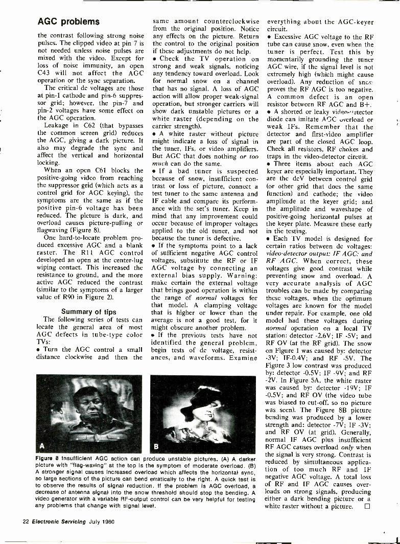
AGC problemsthe contrast following strong noisepulses. The clipped video at pin 7 isnot needed unless noise pulses aremixed with the video. Except forloss of noise immunity, an openC43 will not affect the AGCoperation or the sync separation.
The critical dc voltages are thoseat pin -1 cathode and pin -6 suppres-sor grid; however, the pin -7 andpin -2 voltages have some effect onthe AGC operation.
Leakage in C62 (that bypassesthe common screen grid) reducesthe AGC, giving a dark picture. Italso may degrade the sync andaffect the vertical and horizontallocking.
When an open C61 blocks thepositive -going video from reachingthe suppressor grid (which acts as acontrol grid for AGC keying), thesymptoms are the same as if thepositive pin -6 voltage has beenreduced. The picture is dark, andoverload causes picture -pulling orflagwaving (Figure 8).
One hard -to -locate problem pro-duced excessive AGC and a blankraster. The R11 AGC controldeveloped an open at the center -lugwiping contact. This increased theresistance to ground, and the moreactive AGC reduced the contrast(similar to the symptoms of a largervalue of R90 in Figure 2).
Summary of tipsThe following series of tests can
locate the general area of mostAGC defects in tube -type colorTVs: Turn the AGC control a smalldistance clockwise and then the
same amount counterclockwisefrom the original position. Noticeany effects on the picture. Returnthe control to the original positionif these adjustments do not help. Check the TV operation onstrong and weak signals, noticingany tendency toward overload. Lookfor normal snow on a channelthat has no signal. A loss of AGCaction will allow proper weak -signaloperation, but stronger carriers willshow dark unstable pictures or awhite raster (depending on thecarrier strength). A white raster without picturemight indicate a loss of signal inthe tuner, IFs, or video amplifiers.But AGC that does nothing or toomuch can do the same. If a bad tuner is suspectedbecause of snow, insufficient con-trast or loss of picture, connect atest tuner to the same antenna andIF cable and compare its perform-ance with the set's tuner. Keep inmind that any improvement couldoccur because of improper voltagesapplied to the old tuner, and notbecause the tuner is defective. If the symptoms point to a lackof sufficient negative AGC controlvoltages, substitute the RF or IFAGC voltage by connecting anexternal bias supply. Warning:make certain the external voltagethat brings good operation is withinthe range of normal voltages forthat model. A clamping voltagethat is higher or lower than theaverage is not a good test, for itmight obscure another problem. If the previous tests have notidentified the general problem,begin tests of dc voltage, resist-ances, and waveforms. Examine
Figure 8 Insufficient AGC action can produce unstable pictures. (A) A darkerpicture with "flag-waving" at the top is the symptom of moderate overload. (B)A stronger signal causes increased overload which affects the horizontal sync,so large sections of the picture can bend erratically to the right. A quick test isto observe the results of signal reduction. If the problem is AGC overload, adecrease of antenna signal into the snow threshold should stop the bending. Avideo generator with a variable RF-output control can be very helpful for testingany problems that change with signal level.
everything about the AGC-keyercircuit. Excessive AGC voltage to the RFtube can cause snow, even when thetuner is perfect. Test this bymomentarily grounding the tunerAGC wire, if the signal level is notextremely high (which might causeoverload). Any reduction of sncvproves the RF AGC is too negative.A common defect is an openresistor between RF AGC and B+. A shorted or leaky video-,Aectordiode can imitate AGC overload orweak IFs. Remember that thedetector and first -video amplifierare part of the closed AGC loop.Check all resistors, RF chokes andtraps in the video -detector circuit. Three items about each AGCkeyer are especially important. Theyare the dcV between control grid(or other grid that does the samefunction) and cathode; the videoamplitude at the keyer grid; andthe amplitude and waveshape ofpositive -going horizontal pulses atthe keyer plate. Measure these earlyin the testing. Each TV model is designed forcertain ratios between dc voltages:video -detector output; IF AGC; andRF AGC. When correct, thesevoltages give good contrast whilepreventing snow and overload. Avery accurate analysis of AGCtroubles can be made by comparingthese voltages, when the optimumvoltages are known for the modelunder repair. For example, one oldmodel had these voltages duringnormal operation on a local TVstation: detector -2.6V; IF -5V; andRF OV (at the RF grid). The snowon Figure 1 was caused by: detector-3V; IF -0.4V; and RF -5V. TheFigure 3 low contrast was producedby: detector -0.5V; IF -9V; and RF-2V. In Figure 5A, the white rasterwas caused by: detector -19V; IF-0.5V; and RF OV (the video tubewas biased to cut-off, so no picturewas seen). The Figure 8B picturebending was produced by a lowerstrength and: detector -7V; IF -3V;and RF OV (at grid). Generally,normal IF AGC plus insufficientRF AGC causes overload only whenthe signal is very strong. Contrast isreduced by simultaneous applica-tion of too much RF and IFnegative AGC voltage. A total lossof RF and IF AGC causes over-loads on strong signals, producingeither a dark bending picture or awhite raster without a picture. 0
22 Electronic Servicing July 1980
Consumer Servicing_RCA... chroma...
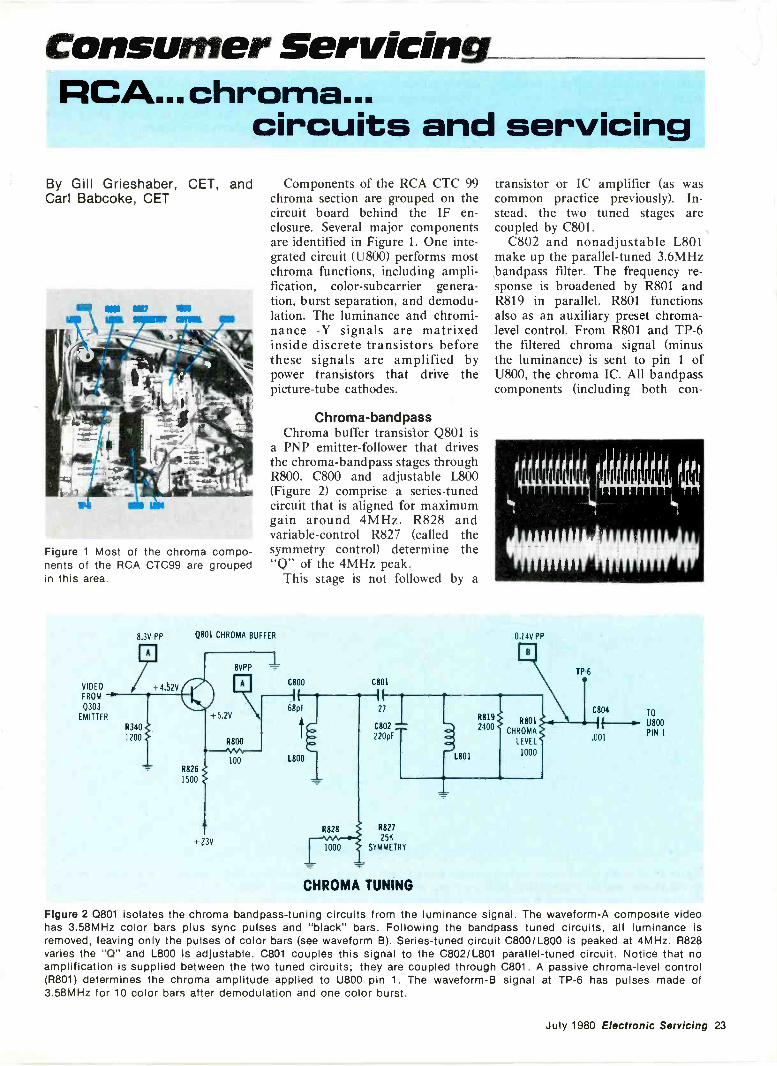
circuits and servicingBy Gill Grieshaber, CET, and Components of the RCA CTC 99Carl Babcoke, CET chroma section are grouped on the
circuit board behind the IF en -
Figure 1 Most of the chroma compo-nents of the RCA CTC99 are groupedin this area.
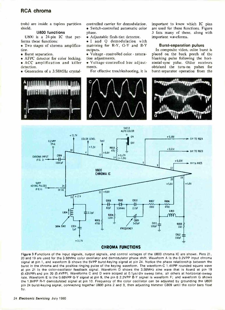
closure. Several major componentsare identified in Figure 1. One inte-grated circuit (U800) performs mostchroma functions, including ampli-fication, color-subcarrier genera-tion, burst separation, and demodu-lation. The luminance and chromi-nance -Y signals are matrixedinside discrete transistors beforethese signals are amplified bypower transistors that drive thepicture -tube cathodes.
Chroma-bandpassChroma buffer transistor Q801 is
a PNP emitter -follower that drivesthe chroma-bandpass stages throughR800. C800 and adjustable L800(Figure 2) comprise a series -tunedcircuit that is aligned for maximumgain around 4MHz. R828 andvariable -control R827 (called thesymmetry control) determine the"Q" of the 4MHz peak.
This stage is not followed by a
transistor or IC amplifier (as wascommon practice previously). In-stead, the two tuned stages arecoupled by C801.
C802 and nonadjustable L801make up the parallel -tuned 3.6MHzbandpass filter. The frequency re-sponse is broadened by R801 andR819 in parallel. R801 functionsalso as an auxiliary preset chroma-level control. From R801 and TP-6the filtered chroma signal (minusthe luminance) is sent to pin 1 ofU800, the chroma IC. All bandpasscomponents (including both con -
'f ti
400001100
8.3V PP
VIDEO
FROM
Q303
EMITTER
Q801 CHROMA BUFFER
+23V
R827
25K
1000 SYMMETRY
CHROMA TUNING
0.14V PP
TP-6
.001
TO
U800PIN 1
Figure 2 Q801 isolates the chroma bandpass-tuning circuits from the luminance signal. The waveform -A composite videohas 3.58MHz color bars plus sync pulses and "black" bars. Following the bandpass tuned circuits, all luminance isremoved, leaving only the pulses of color bars (see waveform B). Series -tuned circuit C800/L800 is peaked at 4MHz. R828varies the "Q" and L800 is adjustable. 0801 couples this signal to the C802/L801 parallel -tuned circuit. Notice that noamplification is supplied between the two tuned circuits; they are coupled through C801. A passive chroma-level control(R801) determines the chroma amplitude applied to U800 pin 1. The waveform -B signal at TP-6 has pulses made of3.58MHz for 10 color bars after demodulation and one color burst.
July 1980 Electronic Servicing 23
RCA chroma
trols) are inside a topless partitionshield.
U800 functionsU800 is a 24 -pin IC that per-
forms these functions: Two stages of chroma amplifica-tion. Burst separation. AFPC detector for color locking. ACC amplification and killerdetection. Generation of a 3.58MHz crystal -
controlled carrier for demodulation. Switch -controlled automatic colorphase. Adjustable flesh -tint detector. I and Q demodulation withmatrixing for R -Y, G -Y and B -Youtputs. Voltage - controlled color - satura-tion adjustments. Voltage -controlled hue adjust-ments.
For effective troubleshooting, it is
important to know which IC pinsare used for these functions. Figure3 lists many of these, along withimportant waveforms.
Burst -separation pulsesIn composite video, color burst is
placed on the back porch of theblanking pulse following the hori-zontal -sync pulse. Older receiversobtained the turn -on pulses forburst -separator operation from the
0.2 VPP
TP-6
ICHROMA INPUT 904, 1
(FIG 2) 1. II--1000 pF
5VPPKEYING PULSES
(FIG 4)
24
OV DC
+11.7V
V COLOR LEVELTINT
18
16
4
+11V
L804 t 1=1.
Ti/SKIN TINT C814 ji
1µF
+11.7V
+7.2V
S4212
AUTO COLOR
0ON
R811
+6.6V470
17
U800CHROMA IC
21 +8.6V
R805
4700
14
C808 Y800
101
82pF
R8041200
3.58MHz
OFF
+5.58V
+5.51V
10
20
+5.6V
C810 R807 R806
2.7pF1000 4700
/ C80'95-25pF
FREQUENCY
CHROMA FUNCTIONS
+5.63V
1803
-10001
19
C811 - R808100pF T 330
C812
150pF
GY TO R824
B -Y TO R823
R -Y to R825
+5.6V
Figure 3 Functions of the input signals, output signals, and control voltages of the U800 chroma IC are shown. Pins 21,20 and 19 are used for the 3.58MHz color oscillator and demodulator phase shift. Waveform A is the 0.2VPP input chromasignal at pin 1, and waveform B shows the 5VPP burst -keying signal at pin 24. Notice the phase relationship between theburst in the chroma and the positive ringing pulse of the keying waveform. The waveform -C 1.4VPP rounded square waveat pin 21 is the color -oscillator feedback signal. Waveform D shows the 3.58MHz sine wave that is found at pin 19(0.43VPP) and pin 20 (0.4VPP). Waveforms C and D were scoped at 0.1ps/div sweep time; all others at horizontal -sweeprate. Waveform E is the 0.68VPP G -Y signal at pin 9, the pin 8 2.2VPP B -Y signal is waveform F; and waveform G showsthe 1.9VPP R -Y demodulated signal at pin 10. Frequency of the color oscillator can be adjusted by grounding the U800pin 24 burst -keying signal, connecting together U800 pins 2 and 3, then adjusting trimmer C809 until the color bars floatby.
24 Electronic Servicing July 1980
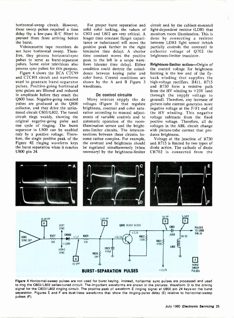
horizontal -sweep circuit. However,these sweep pulses required a timedelay (by a low-pass R/C filter) toprevent them from arriving beforethe burst.
Videocassette tape recorders donot have horizontal sweep. There-fore, they process horizontal -syncpulses to serve as burst -separatorpulses. Some color televisions alsoprocess sync pulses for this purpose.
Figure 4 shows the RCA CTC99and CTC101 circuit and waveformsused to generate burst -separatorpulses. Positive -going horizontalsync pulses are filtered and reducedin amplitude before they reach theQ800 base. Negative -going roundedpulses are produced at the Q800collector, and they drive the series -tuned circuit C803/L802. The tunedcircuit rings weakly, showing theoriginal negative -going pulse andone cycle of ringing. The burstseparator in U800 can be enabledonly by a positive voltage. There-fore, the single positive peak of theFigure 4E ringing waveform keysthe burst separation when it reachesU800 pin 24.
/MO A
/111111111MIIIIIIIMMINIxo Lam
10.4V PP
EJ
U301
SYNC SEP
VERT
SYNC
CR800
+1.08V
HORIZ
SYNC
10 VPP
For proper burst separation andsolid color locking, the values ofC803 and L802 are very critical. Alonger time constant (larger capaci-tance or inductance) will move thepositive peak farther to the right(excessive time delay). A shortertime constant moves the positivepeak to the left in a scope wave-form (shorter time delay). Eithercondition could destroy the coinci-dence between keying pulse andcolor burst. Correct conditions areshown by the A and B Figure 3waveforms.
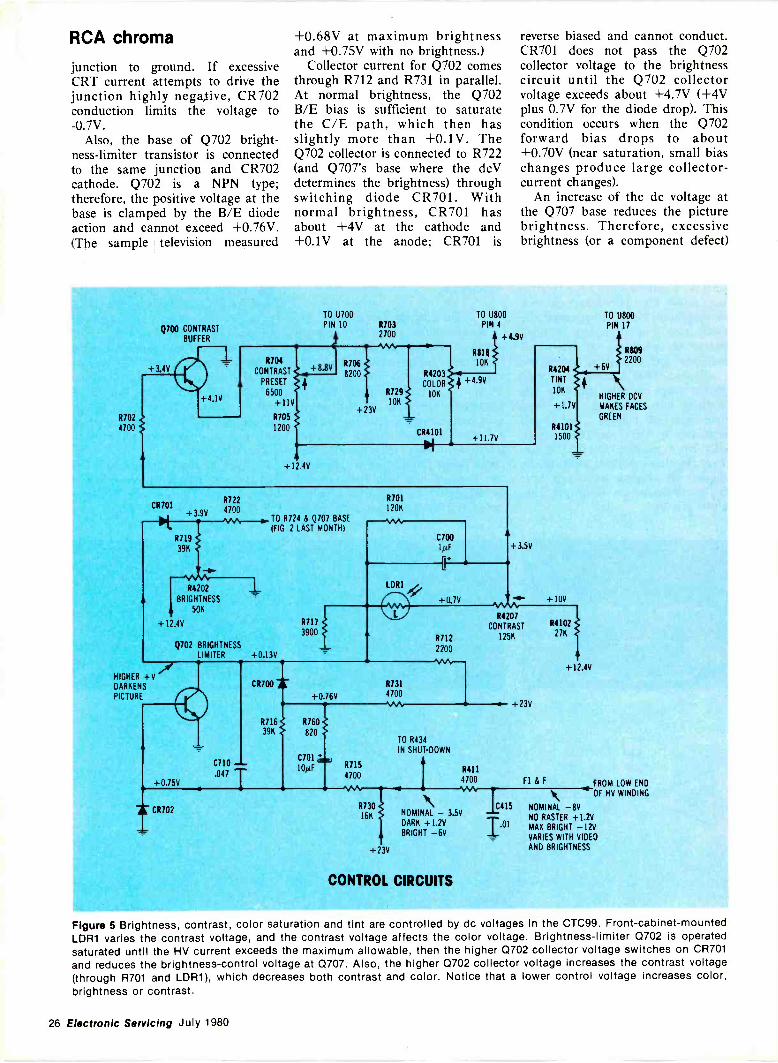
Dc control circuitsMany sources supply the dc
voltages (Figure 5) that regulatebrightness, contrast and color satu-ration according to manual adjust-ments of variable controls and toautomatic operation of the room -illumination sensor and the bright-ness -limiter circuits. The intercon-nections between these circuits be-come rather complex. For example,the contrast and brightness shouldbe regulated simultaneously (whennecessary) by the brightness -limiter
9
R820
18K
1.2V PP
0823470,T
circuit and by the cabinet -mountedlight -dependent resistor (LDR) thatmonitors room illumination. This isdone by connecting a resistorbetween LDR1 light sensor (whichpartially controls the contrast) tocollector voltage of Q702 thebrightness -limiter transistor.
Brightness -limiter action-Origin ofthe control voltage for brightnesslimiting is the low end of the fly-back winding that supplies thehigh -voltage rectifiers. R411, R715and R730 form a resistive pathfrom the HV winding to +23V (andthrough the supply voltage toground). Therefore, any increase ofpicture -tube current generates morenegative voltage at the F/F1 end ofthe HV winding. This negativevoltage subtracts from the fixedpositive voltage. Therefore, all dcvoltages in the ABL circuit changewith picture -tube current that pro-duces brightness.
Voltage at the junction of R730and R715 is limited by two types ofdiode action. The cathode of diodeCR702 is connected from the
5V PP 5.1VPP
Q800 BURST KEYERC803
.0068+0.11V
+2.1V
R822
1500
BURST -SEPARATION PULSES
R82I4100
L802
OV DC
PULSES
TO U800PIN 24
HORIZ
SWEEP
PULSES
Figure 4 Horizontal -sweep pulses are not used for burst keying. Instead, horizontal sync pulses are processed and usedto ring the C803/L802 series -tuned circuit. The important waveforms are shown in the pictures. Waveform D is the drivingsignal for the C803/L802 ringing circuit. The positive peak of waveform E ringing signal at U800 pin 24 keys -on the burstseparation. Figures E and F are dual -trace waveforms that show the ringing -pulse delay (E) relative to horizontal -sweeppulses (F).
July 1980 Electronic Servicing 25
RCA chroma
junction to ground. If excessiveCRT current attempts to drive thejunction highly negative, CR702conduction limits the voltage to-0.7V.
Also, the base of Q702 bright-ness -limiter transistor is connectedto the same junction and CR702cathode. Q702 is a NPN type;therefore, the positive voltage at thebase is clamped by the B/E diodeaction and cannot exceed +0.76V.(The sample television measured
+0.68V at maximum brightnessand +0.75V with no brightness.)
Collector current for Q702 comesthrough R712 and R731 in parallel.At normal brightness, the Q702B/E bias is sufficient to saturatethe C/E path, which then hasslightly more than +0.1V. TheQ702 collector is connected to R722(and Q707's base where the dcVdetermines the brightness) throughswitching diode CR701. Withnormal brightness, CR701 hasabout +4V at the cathode and+0.1V at the anode; CR701 is
reverse biased and cannot conduct.CR701 does not pass the Q702collector voltage to the brightnesscircuit until the Q702 collectorvoltage exceeds about +4.7V (+4Vplus 0.7V for the diode drop). Thiscondition occurs when the Q702forward bias drops to about+0.70V (near saturation, small biaschanges produce large collector -current changes).
An increase of the dc voltage atthe Q707 base reduces the picturebrightness. Therefore, excessivebrightness (or a component defect)
Q700 CONTRASTBUFFER
TO U700 TO U800
PIN 10 R703 PIN 42700
R704
CONTRAST +8.80 R706
8200PRESET
6500
+11V+23V
R702 R705
4700 1200
+12 4V
CR701R722
+3.9V 4100
R719
39K
R4202
BRIGHTNESS
A 506
TO R724 & Q707 BASE(FIG. 2 LAST MONTH)
+12.4V R717
3900
Q702 BRIGHTNESSLIMITER +0.13V
R729
10K
R81810K
R4203
COLOR +4.9010K
CR4101+1I.7V
+4.9V
R701
120K
-VV4C700IptF
+0.7V
R7I22200
HIGHER +VDARKENS
PICTURE
C710
.047+0.75V
CR700
+0.76V
R731
4100
R4207
CONTRAST
125K
R7I6 R760
82039K
C701
10p.F R715
4700
I CR702
TO R434
IN SHUT -DOWN
+23V
R411
4700 F I & F
R730
16K
+23V
NOMINAL - 3.5VDARK +1.2VBRIGHT -6V
CONTROL CIRCUITS
1.01
R4204
TINT
10K
+1.7V
R41011500
TO U800PIN 17
R809
+6V \HIGHER DCV
MAKES FACES
GREEN
2200
FROM LOW END
4 -OF HO WINDING
C415 NOMINAL -8VNO RASTER +1.2VMAX BRIGHT -12VVARIES WITH VIDEOAND BRIGHTNESS
Figure 5 Brightness, contrast, color saturation and tint are controlled by dc voltages In the CTC99. Front -cabinet -mountedLDR1 varies the contrast voltage, and the contrast voltage affects the color voltage. Brightness -limiter Q702 is operatedsaturated until the HV current exceeds the maximum allowable, then the higher Q702 collector voltage switches on CR701and reduces the brightness -control voltage at Q707. Also, the higher Q702 collector voltage increases the contrast voltage(through R701 and LDR1), which decreases both contrast and color. Notice that a lower control voltage increases color,brightness or contrast.
26 Electronic Servicing July 1980
that increases the Q702 de voltageabove about +4.7V produces thiscounter action, which reduces thebrightness. For example, an openQ702 probably would cause a blackraster. But a shorted CR701 in-creases the brightness to maximumjust short of blooming.
For troubleshooting brightnessproblems, it is important to knowthat a more -positive dc voltage atthe Q707 base (also base andemitter of Q703 video buffer)darkens the picture, while a less -positive voltage brightens thepicture.
The Q702 higher collector voltageduring excessive brightness alsoreduces the color level and thecontrast. Dc voltage at the centerlug of R4207 contrast control isisolated and increased slightly byQ700 emitter follower that drivesthe preset contrast control andfinally reaches U700 luminance -ICpin 10. Increased positive voltage atpin 10 decreases the picture con-trast, and a decreased voltageincreases the contrast.
Additionally, the LDR resistanceand the Q702 collector voltagetogether determine the dc voltage atthe low -voltage end of the R4207contrast control. Stronger lightfalling on the LDR reduces theresistance. Therefore, higher roomillumination increases the contrastby decreasing the dc voltage at thejunction of LDR1 and R4207.Notice that this contrast voltagedoes not affect the Q702 collectorvoltage and the brightness, but thehigher Q702 collector voltage dur-ing times of excessive picturebrightness does come through R701and LDR1 to the contrast controlwhere it decreases the contrast.
Variation of the contrast dcvoltage also changes the colorsaturation level. Q700 emitter dcvoltage is reduced by voltage dividerR703/R729 and then is applied tothe low -voltage end of color -controlR4203. A lower dc voltage from thecenter lug of R4203 increases thecolor level, and a higher voltagedecreases the amount of color. Thereason for diode CR4101 is notknown from these tests. Perhaps itminimizes start-up transients in thecolor circuit.
Color -output stagesMatrixing G -Y with Y luminance
was illustrated last month, includ-ing luminance waveforms of color
bars with the TV color controlturned down. Only the three color -output transistors (called drivers)are located on the small circuitboard (Figure 6) that contains a fewcomponents, spark gaps and thepicture -tube socket. The drive con-trols, bias controls and matrixingtransistors are all on the maincircuit board.
The CRT -socket board has aseparate plug-in focus socket with alarge spark gap (Figure 6B). Evi-dently, this is required because ofthe high 8kV focus voltage.
Output waveforms-Figure 7 showsfour waveforms for each of thethree color power -output stages.The top trace is the matrix transis-tor base waveform. Matrix collectorwaveform is the second trace. Thisis a composite of chroma and videosince the luminance was added atthe emitter. The many narrowpulses that mark the bar's edges
Figure 6 (A) A back -side view of thecircuit board that contains the CRTsocket shows three power transistorsand a few components. Matrixingtransistors, drive controls and biascontrols are on the main circuit board.(B) The CRT focus pin is a separateassembly that has a large spark gap.
are in the luminance signal. Thirdtrace is the driver transistor emitterwaveform. The fourth trace showsthe driver collector waveform that issupplied to the proper CRTcathode.
Notice in the Figure 5 schematiclast month that the only componentbetween the second and third wave-forms is a 2704 resistor. Therefore,
Figure 7 (A) Top trace is the 0.62VPPG -Y signal at the Q705 base; secondtrace is the 4.5VPP Q705 collectorsignal; third trace is the 1.05VPPemitter signal of Q2; and fourth traceis the 90VPP collector signal thatdrives the green CRT cathode. (B) Toptrace is the 2.3VPP B -Y signal at theQ704 base; second trace is the 5VPP0704 collector signal; third trace isthe 1.1VPP drive signal at the 01emitter; fourth trace is the 120VPP 01collector signal that drives the blueCRT cathode. (C) Top trace is the1.9VPP R -Y signal at the base of0706; second trace is the 7.6VPPQ706 collector signal; third trace isthe 1.3VPP emitter input signal at 03;fourth trace is the 145VPP Q3 collec-tor signal that drives the red CRTcathode. Refer to page 38, JuneElectronic Servicing for the completematrixing schematic.
July 1980 Electronic Servicing 27
RCA Chroma
both waveforms should be identicalexcept for amplitude. They are not.
#teetkilsr.
Figure 8 These scope traces helpclarify the reason for the waveshapechange between the matrix collectorand the driver emitter. The base is notbypassed, but it has a 1000Q resistor.Therefore, the base/emitter constantcurrent transfers some emitter wave-form to the base. Of course, the onlytrue input waveform is between baseand emitter (not base or emitter toground). The top waveform was ob-tained by floating the scope betweenemitter and base of Q3 red driver. Thiswaveform is quite different from eitherbase or emitter waveforms in Figure 7.A small hum from floating the scopebroadened the horizontal lines of thewaveform.
The unbypassed base has an un-wanted signal that subtracts fromthe emitter signal to form thecorrect input.
This is made clear by the wave-forms of Figure 8. For the toptrace, the scope was connectedbetween base and emitter (not toground). The bottom trace wasmade normally between driver col-lector and ground. Notice that thetwo waveshapes are identical (ex-cept for some hum and noise thatbroadened the horizontal lines).
Practical servicingBecause of the many intercon-
nections between luminance andchrominance circuits, it is best totroubleshoot them as one section.
A good wide -bandwidth triggeredscope and an accurate digitalmultimeter are the two essentialtest instruments. In most cases, thescope should be used to locate astage that might have a defect.Then the DMM functions of volt-age and resistance measurementsshould be employed to pinpoint thetrouble area. The accurate but
simplified schematics used duringthis series have been especiallyprepared to show input and outputsignals and all important wave-forms.
The extreme density of compo-nents on the few circuit boards innew models of most brands bringproblems of locating the parts thatrequire testing. Compounding thecustomary hazards (of ruining agood component while makingtests) are the closeness of leadwires. Insulated hook types ofprobes should be used. It is danger-ous to use large test probes thatcan slip between two conductorsand possibly ruin some solid-statedevice or other component. Re-member, a diode, IC or transistorcan blow before a fuse can protectit.
In -circuit tests are essentialEach RCA CTC99 has approxi-
mately five ICs, 33 transistors, andSCRs, and more than 50 diodes,not including the devices in tunersand tuner -control circuits. All butone or two are soldered to boards.
Electronic Servicing
is Available inMICROFORM
1FOR INFORMATION
WRITE:
University Microfilms International300 North Zeeb Road 18 Bedford RowAnn Arbor, Mich. 48106 London, WC1R 4EJU.S.A. England
28 Electronic Servicing July 1980
Such large numbers can bringserious problems.
These solid-state devices shouldnot be removed for testing orreplacement unless absolutelynecessary. Access to the bottom ofthe circuit board is difficult unlessall connecting wires are unpluggedand the chassis removed from thecabinet. Even with good accessi-bility, much valuable time can bewasted by unsoldering and solder-ing components that are not de-fective. Therefore, these removal ordisconnecting operations must bekept to a minimum.
The best solution to these prob-lems is for each technician toperform all possible tests beforedisconnecting or removing any com-ponents.
Integrated circuits can be testedpartially by examining the inputand output signals and verifyingthat all essential dc voltages arereaching the IC. If no breaks canbe found in the wiring, and the dcvoltages are correct but the outputsignal is missing, then possibly theIC needs to be tested by replace-ment.
Many transistors can be testedin -circuit by instruments designedfor that function. A few transistorsare paralleled by low circuit re-sistances that make in -circuit testsunreliable. These should be re-moved for out -of -circuit tests.
Testing diodesIn -circuit testing of diodes has
been of questionable value in thepast. The internal resistance of anydiode varies with the applied volt-age. In ohmmeters, the appliedvoltage depends on the currentdrawn. Low ohmmeter current,therefore, increases diode resistanceso much that it sometimes equalsother resistances in the circuit.Identification of the various resis-tances is difficult.
During research on CTC99troubleshooting, it became evidentthat a fast and dependable methodof testing diodes in -circuit wasneeded. Several experiments led tothe construction of an adapter to beused with a digital multimeter (orother voltmeter) as a readout.
The diode -test adapter does notmeasure diodes by their resistances.Instead, a substantial current isdrawn through each diode and thevoltage drop across the diode ismeasured.
Test results-Very good resultswere obtained when more than 24of the CTC99 main -board diodeswere tested for forward -bias andreverse-biase voltages.
Almost all diodes measured be-tween 0.67V and 0.69V. CR421gave a reading of 0.628V. Twoshowed readings of less than 0.60V.CR403 (which rectifies the +215Vsource) measured 0.599V, possiblybecause of collector -to -base currentin the color -output power transis-tors. The CR105 damper diodemeasured 0.542V, which increasedto 0.600V when the Q100 hori-zontal -output transistor was un-plugged. The four bridge rectifiersgave dependable and consistentreadings.
Only two diodes were loaded soheavily by the circuit that thereadings were of no value. One ofthe horizontal -centering diodesmeasured 0.126V for both polari-ties, while the other had thecentering jumper across it and thushad OV.
Reversed readings-When theadapter test leads were connectedto nothing (infinite resistance), thefull 19V (with new batteries) wassent to the readout meter. DMMscan endure this overload on the 2Vreadout range without damage.However, for reverse -bias readings,the 20V range should be used.
Reverse -bias voltage readingsmade out -of -circuit indicate onlyinternal diode leakage. However,in -circuit readings show diode leak-age in parallel with circuit re-sistances. Therefore, low -voltagereadings 'might indicate either diodeleakage or a low -value circuitresistance. Study the schematic toverify or disprove the possibility ofexcessive circuit loading.
The same 24 CTC99 in -circuitdiodes were tested also for reverse -bias readings. Two did not over-
range on the 2V range. CR402measured 1.8V and CR401 showed1.7V with reversed test leads. TheCR423 measurement was 4.04V.Four main bridge diodes showedreverse voltages of about 16V.Those diodes without low -valueshunting resistances gave readingsof 18V to 19V.
These readings make it safe tostate: When measured in -circuit,any diode that activates the over -range on the 2V range (whenreverse bias is applied from the
diode -test adapter) should be con-sidered normal.
Transistor junctions, high -voltagediodes, phase -detector diodes, andLEDs also can be tested forforward voltage and leakage by thediode -test adapter and a readoutmeter.
CommentsLuminance and chrominance
problems should be tested with ascope. All the signals (including the3.58MHz color carrier) can bescoped easily. However, if theproblem involves either excessivebrightness or a dark picture, alldiodes in luminance and chromi-nance circuits should be tested bythe voltage -drop method. Diodesusually fail (if they fail) by becom-ing shorted. Therefore, shorteddiodes should be suspected first.
When these tests fail to find theproblem, a multimeter should beused for dc -voltage analysis. Forbrightness problems, measure thefocus and screen voltages at thepicture tube and make certain theheater has the proper amplitude ofhorizontal pulses. Then measurethe dc voltages beginning withthose in the three color powertransistors and working upstreamto the matrixing transistors. Re-member, the luminance andchrominance signals join there, soidentify whether the luminance orchroma voltage is incorrect. Con-tinue to move back upstream untilthe problem stage is located.
Use the following table to helplocate the shorted diode causing ablack raster or a bright picture:SHORTEDDIODE SYMPTOM
CR703 bright pictureCR709 very brightCR708 slightly brighterCR715 no changeCR713 no changeCR712 no rasterCR700 no changeCR701 very brightCR702 no rasterCR700 no changeCR706 bad verticalCR707 bad verticalCR711 no rasterCR800 no changeCR710 extremely bright
with horiz noise
Next monthVertical sweep and servicing
problems will be the subjects nextmonth.
July 1980 Electronic Servicing 29
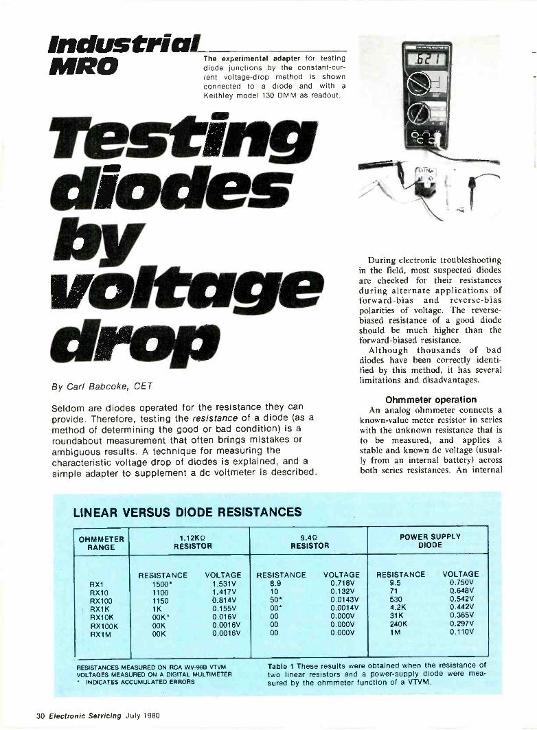
IndustrialMRO The experimental adapter for testing
diode junctions by the constant -cur -tent voltage -drop method is shownconnected to a diode and with a
Keithley model 130 DMM as readout.
restingdiodesbyvoltesgedropBy Carl Babcoke, CET
Seldom are diodes operated for the resistance they canprovide. Therefore, testing the resistance of a diode (as amethod of determining the good or bad condition) is aroundabout measurement that often brings mistakes orambiguous results. A technique for measuring thecharacteristic voltage drop of diodes is explained, and asimple adapter to supplement a dc voltmeter is described.
During electronic troubleshootingin the field, most suspected diodesare checked for their resistancesduring alternate applications offorward -bias and reverse -biaspolarities of voltage. The reverse -biased resistance of a good diodeshould be much higher than theforward -biased resistance.
Although thousands of baddiodes have beenfied by this method, it has severallimitations and disadvantages.
Ohmmeter operationAn analog ohmmeter connects a
known -value meter resistor in serieswith the unknown resistance that isto be measured, and applies astable and known dc voltage (usual-ly from an internal battery) acrossboth series resistances. An internal
LINEAR VERSUS DIODE RESISTANCES
OHMMETERRANGE
1.12K0RESISTOR
9.40RESISTOR
POWER SUPPLYDIODE
RESISTANCE VOLTAGE RESISTANCE VOLTAGE RESISTANCE VOLTAGERX1 1500* 1.531V 8.9 0.718V 9.5 0.750VRX10 1100 1.417V 10 0.132V 71 0.648VRX100 1150 0.814V 50* 0.0143V 530 0.542VRX1K 1K 0.155V 00* 0.0014V 4.2K 0.442VRX1OK OOK* 0.016V 00 0.000V 31K 0.365V
RX100K OOK 0.0016V 00 0.000V 240K 0.297VRX1M OOK 0.0016V 00 0.000V 1M 0.110V
RESISTANCES MEASURED ON RCA WV -98B VTVMVOLTAGES MEASURED ON A DIGITAL MULTIMETER
INDICATES ACCUMULATED ERRORS
Table 1 These results were obtained when the resistance oftwo linear resistors and a power -supply diode were mea-sured by the ohmmeter function of a VTVM.
30 Electronic Servicing July 1980
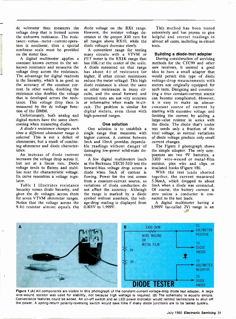
dc voltmeter then measures thevoltage drop that is formed acrossthe unknown resistance. The resis-tance - versus - meter - current opera-tion is nonlinear, thus a specialnonlinear scale must be providedon the meter face.
A digital multiineter applies aconstant known current to the un-known resistance and measures thevoltage drop across the resistance.The advantage for digital readoutsis the linearity, which is as good asthe accuracy of the constant cur-rent. In other words, doubling theresistance also doubles the voltagethat is developed across the resis-tance. This voltage drop then ismeasured by the dc voltage func-tion of the DMM.
Unfortunately, both analog anddigital meters have the same short-coming when measuring diodes.
A diode's resistance changes eachtime a different ohmmeter range isselected. This is not a defect ofohmmeters, but a result of combin-ing ohmmeter and diode character-istics.
An increase of diode currentincreases the voltage drop across it,but not at a linear rate. Diodevoltage tends to flatten and stabi-lize near the characteristic voltage.Its curve resembles a voltage regu-lator.
Table 1 illustrates resistancelinearity versus diode linearity, andgives the dc voltages across themfor seven VTVM ohmmeter ranges.Notice that the voltage across the9.4o resistor almost equals the
diode voltage on the RX1 range.However, the resistor voltage de-creases at the .proper X10 rate forall ranges above RX10, while thediode voltages decrease slowly.
A convenient range for testingmany circuits with a VTVM orFET meter is the RX1K range thathas 10K n at the center of the scale.A diode measured on that rangehas about 4 n of resistance (orhigher, if other circuit resistancesreduce the meter voltage). This highdiode resistance is about the sameas other resistances in many cir-cuits, and the usual forward andreversed tests are not very accurateor informative when made in -cir-cuit. The problem is similar fordigital meters, even those withhigh-powered ranges.
One solutionOne solution is to establish a
single range that measures withhigher current. A current between5mA and 10mA provides dependa-ble readings without danger ofdamaging low -power solid-state de-vices.
A few digital multimeters (suchas the Beckman TECH -310) test theforward -bias voltage drop across adiode when 5mA of current isflowing. Power for the test comesfrom a constant -current source, sovariations of diode conduction donot affect the accuracy. Althoughthe range is marked by a diodesymbol without numbers, the volt-age -drop reading is displayed from0.001V to 1.999V.
This method has been testedextensively and has proven to givehelpful and correct readings inalmost all cases, including in -circuittests.
Building a diode -test adapterDuring consideration of servicing
methods for the CTC99 and othernew receivers, it seemed a goodidea to have a small adapter thatwould permit this type of diodevoltage -drop measurements withmeters not originally equipped forsuch tests. Designing and construc-ting a true constant -current sourcecan become complicated. However,it is easy to make an almost -constant source of current bystarting with excessive voltage andlimiting the current by adding alarge -value resistor in series withthe diode. The diode that's undertest needs only a fraction of thetotal voltage, so normal variationsof diode voltage produce only smallcurrent changes.
The Figure 1 photograph showsthe simple adapter. The only com-ponents are two 9V batteries, a3300 wire -wound or metal -filmresistor, plus wire and clips orinsulated hooks (Figure 1B).
With the test leads shortedtogether, the current measured5.56mA, which dropped to about5mA when a diode was connected.Of course, the battery current iszero unless a conductor is con-nected to the test leads.
A digital multimeter having a1.999V (so-called 2V) range is an
1/440
B 3300 OHM
9V
9V
WIRE WOUND
OR
METAL FILM
TO
. VOLTMETER
POSITIVE
DIODE TESTER
TO
DIODE
ANODE
TO
VOLTME
NEGATIV
TO
DIODE
NODE
Figure 1 (A) All components are visible in this photograph of the constant -current voltage -drop diode test adapter. A largewire -wound resistor was used for stability, not because high wattage Is required. (B) The schematic is equally simple.Convenience features could be added. An on -off switch and an LED power Indicator would remind technicians to shut offthe power. A spring -return polarity -reversing switch would save time If many diode Junctions are to be tested quickly.
July 1980 Electronic Servicing 31
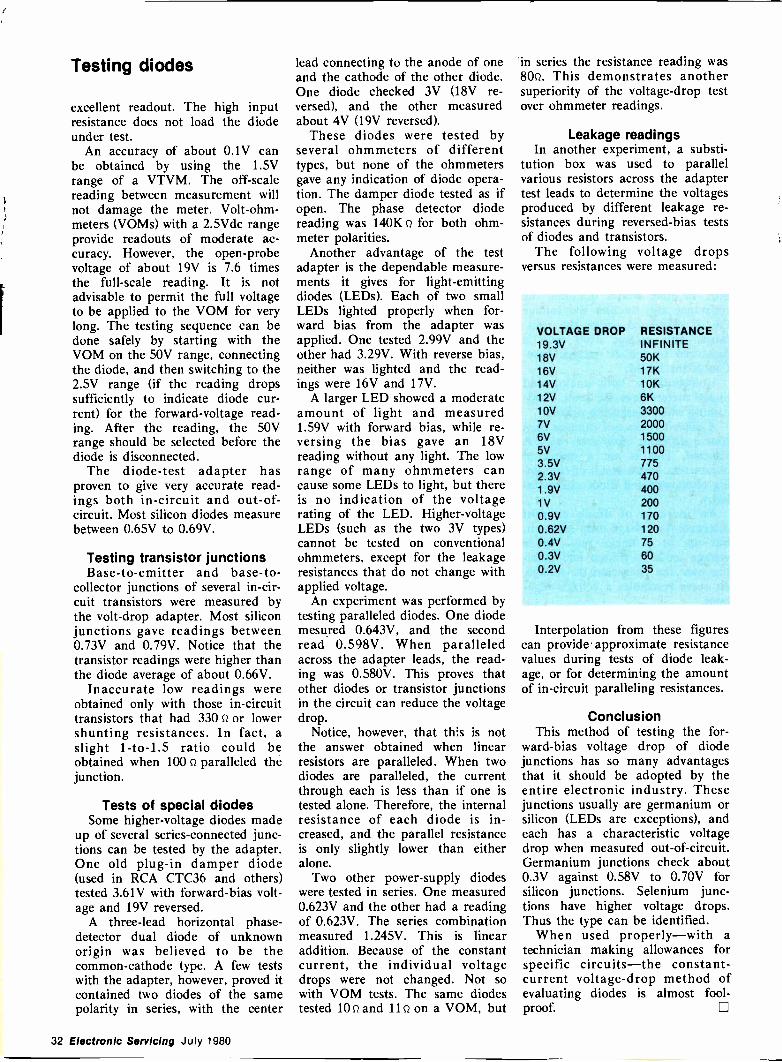
Testing diodes
excellent readout. The high inputresistance does not load the diodeunder test.
An accuracy of about 0.1V canbe obtained by using the 1.5Vrange of a VTVM. The off -scalereading between measurement willnot damage the meter. Volt -ohm-meters (VOMs) with a 2.5Vdc rangeprovide readouts of moderate ac-curacy. However, the open -probevoltage of about 19V is 7.6 timesthe full-scale reading. It is notadvisable to permit the full voltageto be applied to the VOM for verylong. The testing sequence can bedone safely by starting with theVOM on the 50V range, connectingthe diode, and then switching to the2.5V range (if the reading dropssufficiently to indicate diode cur-rent) for the forward -voltage read-ing. After the reading, the 50Vrange should be selected before thediode is disconnected.
The diode -test adapter hasproven to give very accurate read-ings both in -circuit and out -of -circuit. Most silicon diodes measurebetween 0.65V to 0.69V.
Testing transistor junctionsBase -to -emitter and base -to -
collector junctions of several in -cir-cuit transistors were measured bythe volt -drop adapter. Most siliconjunctions gave readings between0.73V and 0.79V. Notice that thetransistor readings were higher thanthe diode average of about 0.66V.
Inaccurate low readings wereobtained only with those in -circuittransistors that had 330 Q or lowershunting resistances. In fact, aslight 1 -to -1.5 ratio could beobtained when 100 Q paralleled thejunction.
Tests of special diodesSome higher -voltage diodes made
up of several series -connected junc-tions can be tested by the adapter.One old plug-in damper diode(used in RCA CTC36 and others)tested 3.61V with forward -bias volt-age and 19V reversed.
A three -lead horizontal phase -detector dual diode of unknownorigin was believed to be thecommon -cathode type. A few testswith the adapter, however, proved itcontained two diodes of the samepolarity in series, with the center
lead connecting to the anode of oneand the cathode of the other diode.One diode checked 3V (18V re-versed), and the other measuredabout 4V (19V reversed).
These diodes were tested byseveral ohmmeters of differenttypes, but none of the ohmmetersgave any indication of diode opera-tion. The damper diode tested as ifopen. The phase detector diodereading was 1401(Q for both ohm-meter polarities.
Another advantage of the testadapter is the dependable measure-ments it gives for light -emittingdiodes (LEDs). Each of two smallLEDs lighted properly when for-ward bias from the adapter wasapplied. One tested 2.99V and theother had 3.29V. With reverse bias,neither was lighted and the read-ings were 16V and 17V.
A larger LED showed a moderateamount of light and measured1.59V with forward bias, while re-versing the bias gave an 18Vreading without any light. The lowrange of many ohmmeters cancause some LEDs to light, but thereis no indication of the voltagerating of the LED. Higher -voltageLEDs (such as the two 3V types)cannot be tested on conventionalohmmeters, except for the leakageresistances that do not change withapplied voltage.
An experiment was performed bytesting paralleled diodes. One diodemesured 0.643V, and the secondread 0.598V. When paralleledacross the adapter leads, the read-ing was 0.580V. This proves thatother diodes or transistor junctionsin the circuit can reduce the voltagedrop.
Notice, however, that this is notthe answer obtained when linearresistors are paralleled. When twodiodes are paralleled, the currentthrough each is less than if one istested alone. Therefore, the internalresistance of each diode is in-creased, and the parallel resistanceis only slightly lower than eitheralone.
Two other power -supply diodeswere tested in series. One measured0.623V and the other had a readingof 0.623V. The series combinationmeasured 1.245V. This is linearaddition. Because of the constantcurrent, the individual voltagedrops were not changed. Not sowith VOM tests. The same diodestested 10Q and 11Q on a VOM, but
in series the resistance reading was80Q. This demonstrates anothersuperiority of the voltage -drop testover ohmmeter readings.
Leakage readingsIn another experiment, a substi-
tution box was used to parallelvarious resistors across the adaptertest leads to determine the voltagesproduced by different leakage re-sistances during reversed -bias testsof diodes and transistors.
The following voltage dropsversus resistances were measured:
VOLTAGE DROP19.3V18V16V14V12V10V7V6V5V3.5V2.3V1.9V1V0.9V0.62V0.4V0.3V0.2V
RESISTANCEINFINITE50K17K10K6K3300200015001100775470400200170120756035
Interpolation from these figurescan provide approximate resistancevalues during tests of diode leak-age, or for determining the amountof in -circuit paralleling resistances.
ConclusionThis method of testing the for-
ward -bias voltage drop of diodejunctions has so many advantagesthat it should be adopted by theentire electronic industry. Thesejunctions usually are germanium orsilicon (LEDs are exceptions), andeach has a characteristic voltagedrop when measured out -of -circuit.Germanium junctions check about0.3V against 0.58V to 0.70V forsilicon junctions. Selenium junc-tions have higher voltage drops.Thus the type can be identified.
When used properly-with atechnician making allowances forspecific circuits-the constant -current voltage -drop method ofevaluating diodes is almost fool-proof.
32 Electronic Servicing July 1980
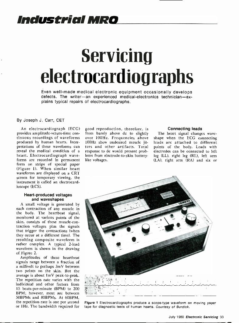
Industrial MRO
ServicingelectrocardiographsEven well -made medical electronic equipment occasionally developsdefects. The writer-an experienced medical -electronics technician-ex-plains typical repairs of electrocardiographs.
By Joseph J. Carr, CET
An electrocardiograph (ECG)provides amplitude -versus -time con-tinuous recordings of waveformsproduced by human hearts. Inter-pretations of these waveforms canreveal the medical condition of aheart. Electrocardiograph wave-forms are recorded in permanentform on strips of special paper(Figure 1). When similar heartwaveforms are displayed on a CRTscreen for temporary viewing, theinstrument is called an electrocard-ioscope (ECS).
Heart -produced voltagesand waveshapes
A small voltage is generated byeach contraction of any muscle inthe body. The heartbeat signal,monitored at various points of theskin, consists of these muscle -con-traction voltages plus the signalsthat trigger the contractions (whenthey occur at a different time). Theresulting composite waveform israther complex. A typical 2 -leadwaveform is shown in the drawingof Figure 2.
Amplitudes of these heartbeatsignals range between a fraction ofa millivolt to perhaps 3mV betweentwo points on the skin. But theaverage is about lmV peak -to -peak.The repetition rate varies with theindividual and other factors from15 beats -per -minute (BPM) to 200BPM; however, most are between50BPMs and 80BPMs. At 60BPM,the repetition rate is one per secondor 1Hz. The bandwidth required for
good reproduction, therefore, isfrom barely above dc to slightlyover 100Hz. Frequencies above100Hz show undesired muscle jit-ters and other artifacts. Totalresponse to dc would present prob-lems from electrode -to -skin battery -like voltages.
Connecting leadsThe heart signal changes wave -
shape when the ECG connectingleads are attached to differentpoints of the body. Leads withelectrodes can be connected to leftleg (LL), right leg (RL), left arm(LA), right arm (RA) and six or
Figure 1 Electrocardiographs produce a scope -type waveform on moving papertape for diagnostic tests of human hearts. Courtesy of Burdick.
July 1980 Electronic Servicing 33
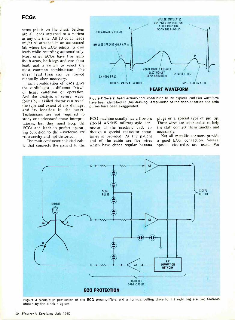
ECGs
seven points on the chest. Seldomare all leads attached to a patientat any one time. All 10 or 11 leadsmight be attached in an automatedlab where the ECG selects its ownleads while recording automatically.Most other ECGs have five leads(both arms, both legs and one chestlead) and a switch to select themost common combinations. Thechest lead then can be movedmanually when necessary.
Each combination of leads givesthe cardiologist a different "view"of heart condition or operation.And the analysis of several wave-forms by a skilled doctor can revealthe type and extent of any damage,and its location in the heart.Technicians are not required tostudy or understand these interpre-tations, but they must keep theECGs and leads in perfect operat-ing condition so the waveforms aretrustworthy and not distorted.
The multiconductor shielded cab-le that connects the patient to the
R
(POLARIZATION PULSE)
IMPULSE SPREADS OVER ATRIA
SA NODE FIRES
IMPULSE WAITS AT AV NODE
IMPULSE STIMULATES
VENTRICLE CONTRACTIONAFTER TRAVELING
DOWN THE BUNDLES
HEART MUSCLE RELAXES
ELECTRICALLYSA NODE FIRES
(DEPOLARIZATION)
Q
IMPULSE AT AV NODE
HEART WAVEFORM
Figure 2 Several heart actions that contribute to the typical lead -two waveformhave been identified in this drawing. Amplitudes of the depolarization and atriapulses have been exaggerated.
ECG machine usually has a five -pinsize -14 AN/MS military -style con-nector at the machine end, al-though a special connector some-times is provided. At the patientend of the cable are five wireswhich have either regular banana
plugs or a special type of pin tip.These wires are color coded to helpthe staff connect them quickly andaccurately.
Not all metallic contacts providea good ECG connection. Severalspecial electrodes are used. For
PATIENT
RA
RL
LA
ECG PROTECTION
A3
RC
SUMMATIONNETWORK
RIGHT LEG
DRIVE CIRCUIT
SIGNAL
r OUTPUT
Figure 3 Neon -bulb protection of the ECG veamplifiers and a hum -cancelling drive to the right leg are two featuresshown by the block diagram.
34 Electronic Servicing July 1980
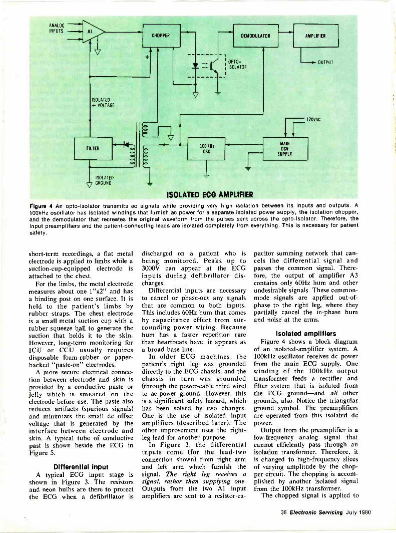
ANALOG --il-INPUTS --11.
CHOPPER
ISOLATED
+ VOLTAGE
FILTER
ISOLATED
v GROUND
r- -1
1
1
.... -
V
DEMODULATOR
--,1 °PTO-!
ISOLATOR
100 kHz
OSC
AMPLIFIER
OUTPUT
120VAC
ISOLATED ECG AMPLIFIER
MAINDCV
SUPPLY
Figure 4 An opto-isolator transmits ac signals while providing very high isolation between its inputs and outputs. A100kHz oscillator has isolated windings that furnish ac power for a separate isolated power supply, the isolation chopper,and the demodulator that recreates the original waveform from the pulses sent across the opto-isolator. Therefore, theinput preamplifiers and the patient -connecting leads are isolated completely from everything. This is necessary for patientsafety.
short-term recordings, a flat metalelectrode is applied to limbs while asuction -cup -equipped electrode isattached to the chest.
For the limbs, the metal electrodemeasures about one 1"x2" and hasa binding post on one surface. It isheld to the patient's limbs byrubber straps. The chest electrodeis a small metal suction cup with arubber squeeze ball to generate thesuction that holds it to the skin.However, long-term monitoring forICU or CCU usually requiresdisposable foam -rubber or paper -backed "paste -on" electrodes.
A more secure electrical connec-tion between electrode and skin isprovided by a conductive paste orjelly which is smeared on theelectrode before use. The paste alsoreduces artifacts (spurious signals)and minimizes the small dc offsetvoltage that is generated by theinterface between electrode andskin. A typical tube of conductivepast is shown beside the ECG inFigure 5.
Differential inputA typical ECG input stage is
shown in Figure 3. The resistorsand neon bulbs are there to protectthe ECG when a defibrillator is
discharged on a patient who isbeing monitored. Peaks up to3000V can appear at the ECGinputs during defibrillator dis-charges.
Differential inputs are necessaryto cancel or phase -out any signalsthat are common to both inputs.This includes 60Hz hum that comesby capacitance effect from sur-rounding power wiring. Becausehum has a faster repetition ratethan heartbeats have, it appears asa broad base line.
In older ECG machines, thepatient's right leg was groundeddirectly to the ECG chassis, and thechassis in turn was grounded(through the power -cable third wire)to ac -power ground. However, thisis a significant safety hazard, whichhas been solved by two changes.One is the use of isolated inputamplifiers (described later). Theother improvement uses the right -leg lead for another purpose.
In Figure 3, the differentialinputs come (for the lead -twoconnection shown) from right armand left arm which furnish thesignal. The right leg receives asignal, rather than supplying one.Outputs from the two Al inputamplifiers are sent to a resistor -ca-
pacitor summing network that can-cels the differential signal andpasses the common signal. There-fore, the output of amplifier A3contains only 60Hz hum and otherundesirable signals. These common -mode signals are applied out -of -phase to the right leg, where theypartially cancel the in -phase humand noise at the arms.
Isolated amplifiersFigure 4 shows a block diagram
of an isolated -amplifier system. A100kHz oscillator receives dc powerfrom the main ECG supply. Onewinding of the 100kHz outputtransformer feeds a rectifier andfilter system that is isolated fromthe ECG ground-and all othergrounds, also. Notice the triangularground symbol. The preamplifiersare operated from this isolated dcpower.
Output from the preamplifier is alow -frequency analog signal thatcannot efficiently pass through anisolation transformer. Therefore, itis changed to high -frequency slicesof varying amplitude by the chop-per circuit. The chopping is accom-plished by another isolated signalfrom the 100kHz transformer.
The chopped signal is applied to
36 Electronic Servicing July 1980
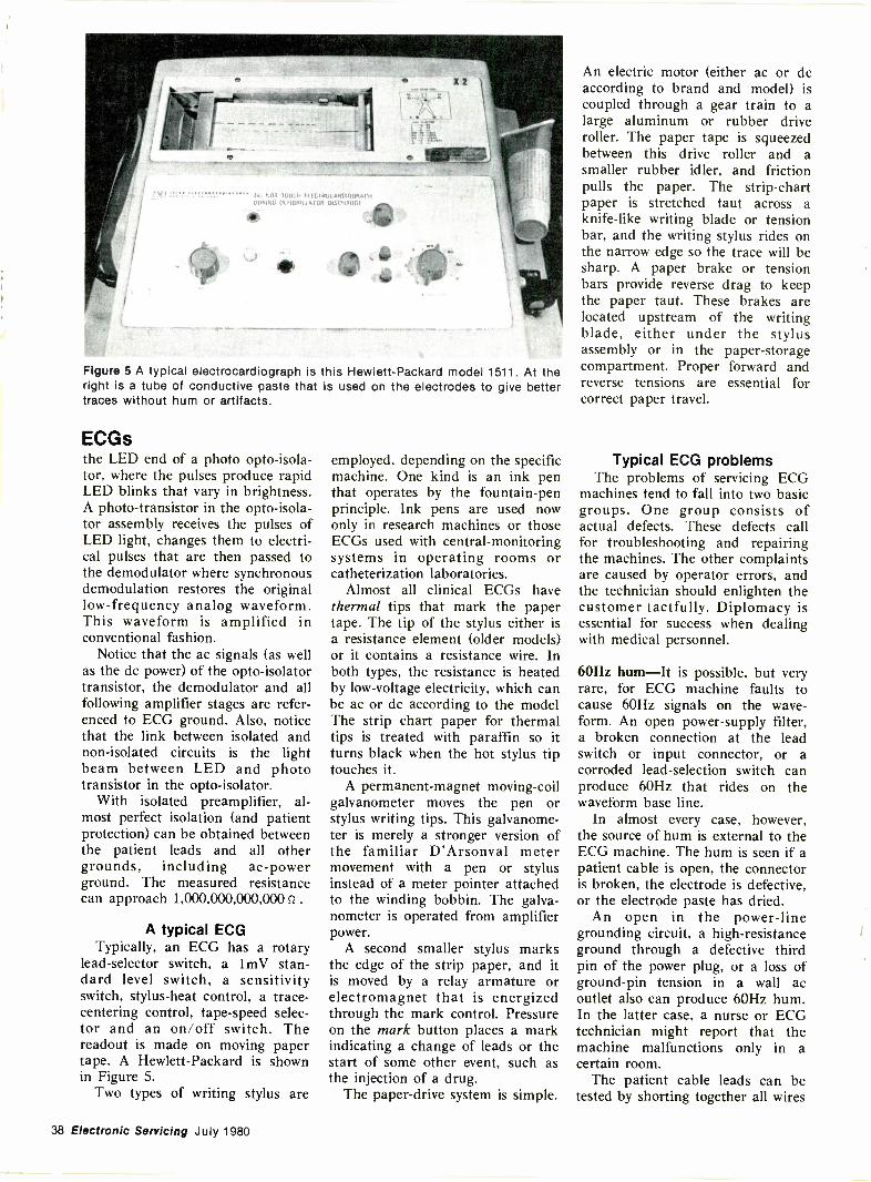
Ott 11101 TOUCH El IC 1{10CARDIOGRAPHOOHING Of T1BHH I A TOO OISCOAMI
Figure 5 A typical electrocardiograph is this Hewlett-Packard model 1511. At theright is a tube of conductive paste that is used on the electrodes to give bettertraces without hum or artifacts.
ECGsthe LED end of a photo opto-isola-tor, where the pulses produce rapidLED blinks that vary in brightness.A photo -transistor in the opto-isola-tor assembly receives the pulses ofLED light, changes them to electri-cal pulses that are then passed tothe demodulator where synchronousdemodulation restores the originallow -frequency analog waveform.This waveform is amplified inconventional fashion.
Notice that the ac signals (as wellas the dc power) of the opto-isolatortransistor, the demodulator and allfollowing amplifier stages are refer-enced to ECG ground. Also, noticethat the link between isolated andnon -isolated circuits is the lightbeam between LED and phototransistor in the opto-isolator.
With isolated preamplifier, al-most perfect isolation (and patientprotection) can be obtained betweenthe patient leads and all othergrounds, including ac -powerground. The measured resistancecan approach 1,000,000,000,000Q .
A typical ECGTypically, an ECG has a rotary
lead -selector switch, a lmV stan-dard level switch, a sensitivityswitch, stylus -heat control, a trace-
centering control, tape -speed selec-tor and an on/off switch. Thereadout is made on moving papertape. A Hewlett-Packard is shownin Figure 5.
Two types of writing stylus are
employed, depending on the specificmachine. One kind is an ink penthat operates by the fountain -penprinciple. Ink pens are used nowonly in research machines or thoseECGs used with central -monitoringsystems in operating rooms orcatheterization laboratories.
Almost all clinical ECGs havethermal tips that mark the papertape. The tip of the stylus either isa resistance element (older models)or it contains a resistance wire. Inboth types, the resistance is heatedby low -voltage electricity, which canbe ac or dc according to the modelThe strip chart paper for thermaltips is treated with paraffin so itturns black when the hot stylus tiptouches it.
A permanent -magnet moving -coilgalvanometer moves the pen orstylus writing tips. This galvanome-ter is merely a stronger version ofthe familiar D'Arsonval metermovement with a pen or stylusinstead of a meter pointer attachedto the winding bobbin. The galva-nometer is operated from amplifierpower.
A second smaller stylus marksthe edge of the strip paper, and itis moved by a relay armature orelectromagnet that is energizedthrough the mark control. Pressureon the mark button places a markindicating a change of leads or thestart of some other event, such asthe injection of a drug.
The paper -drive system is simple.
An electric motor (either ac or dcaccording to brand and model) iscoupled through a gear train to alarge aluminum or rubber driveroller. The paper tape is squeezedbetween this drive roller and asmaller rubber idler, and frictionpulls the paper. The strip -chartpaper is stretched taut across aknife -like writing blade or tensionbar, and the writing stylus rides onthe narrow edge so the trace will besharp. A paper brake or tensionbars provide reverse drag to keepthe paper taut. These brakes arelocated upstream of the writingblade, either under the stylusassembly or in the paper -storagecompartment. Proper forward andreverse tensions are essential forcorrect paper travel.
Typical ECG problemsThe problems of servicing ECG
machines tend to fall into two basicgroups. One group consists ofactual defects. These defects callfor troubleshooting and repairingthe machines. The other complaintsare caused by operator errors, andthe technician should enlighten thecustomer tactfully. Diplomacy isessential for success when dealingwith medical personnel.
60Hz hum-It is possible, but veryrare, for ECG machine faults tocause 60Hz signals on the wave-form. An open power -supply filter,a broken connection at the leadswitch or input connector, or acorroded lead -selection switch canproduce 60Hz that rides on thewaveform base line.
In almost every case, however,the source of hum is external to theECG machine. The hum is seen if apatient cable is open, the connectoris broken, the electrode is defective,or the electrode paste has dried.
An open in the power -linegrounding circuit, a high -resistanceground through a defective thirdpin of the power plug, or a loss ofground -pin tension in a wall acoutlet also can produce 60Hz hum.In the latter case, a nurse or ECGtechnician might report that themachine malfunctions only in acertain room.
The patient cable leads can betested by shorting together all wires
38 Electonic Servicing July 1980
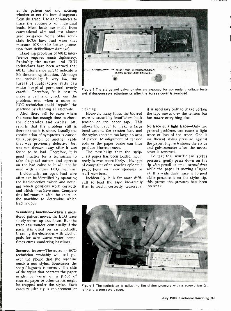
at the patient end and noticingwhether or not the hum disappearsfrom the trace. Use an ohmmeter totrace the continuity of individualleads. Most leads are made fromconventional wire and test almostzero resistance. Some older solid-state ECGs have lead wires thatmeasure 10K iz (for better protec-tion from defibrillator damage).
Handling problems of 60Hz inter-ference requires much diplomacy.Probably the nurses and ECGtechnicians have been warned that60Hz interference might indicate alife -threatening situation. Althoughthe probability is very low, thethreat of malpractice suits canmake hospital personnel overlycareful. Therefore, it is best tomake a call and check out theproblem, even when a nurse orECG technician could "repair" themachine by cleaning an electrode.
Also, there will be cases wherethe nurse has enough time to checkthe electrodes and cables, butreports that the problem still isthere or that it is worse. Usually thecontinuation of symptoms is causedby substitution of another cablethat was previously defective, butwas not thrown away after it wasfound to be bad. Therefore, it isgood practice for a technician totake diagonal cutters and operateon the bad cable so it will not beused with another ECG machine.
Incidentally, an open lead wireoften can be identified by operatingthe lead -selection switch and notic-ing which positions work correctlyand which ones have hum. Comparethis information with the chart onthe machine to determine whichlead is open.
Wandering baseline-When a mon-itored patient moves, the ECG traceslowly moves up and down. But thetrace can wander continually if thepaste has dried on an electrode,Cleaning the electrodes with alcoholpads (or even warm water) some-times cures wandering baselines.
Smeared traces-The nurse or ECGtechnician probably will tell youover the phone that the machineneeds a new stylus. Sometimes thesnap diagnosis is correct. The sideof the stylus that contacts the papermight be worn, or a piece ofcharred paper or other debris mightbe trapped under the stylus. Suchcases require stylus replacement or
00 NOT TOUCH flICTROCARDIOGRAPHDURING OEFIRRIUATOR DISCHARGE
Figure 6 The stylus and galvanometer are exposed for convenient voltage testsand stylus -pressure adjustments after the access cover is removed.
cleaning.However, many times the blurred
trace is caused by insufficient backtension on the paper tape. Thisallows the paper to make a largebend around the tension bar, andthe stylus contacts too large an areaof paper. Misalignment of tensionrods or the paper brake can thusproduce blurred traces.
The possibility that the strip -chart paper has been loaded incor-rectly is even more likely. This typeof complaint often reaches epidemicproportions with new students orstaff members.
Incidentally, it is far more diffi-cult to load the tape incorrectlythan to load it correctly. Generally,
it is necessary only to make certainthe tape moves over the tension barbut under everything else.
No trace or a light trace-Only twogeneral problems can cause a lighttrace or loss of the trace. One isinsufficient stylus pressure againstthe paper. Figure 6 shows the stylusand galvanometer after the accesscover is removed.
To test for insufficient styluspressure, gently press down on thetip with pencil or small screwdriverwhile the paper is moving (Figure7). If a wide dark trace is formedwhile pressure is on the stylus tip,this proves the pressure had beentoo weak.
Figure 7 The technician is adjusting the stylus pressure with a screwdriver (atleft) and a pressure gauge.
July 1980 Electronic Servicing 39
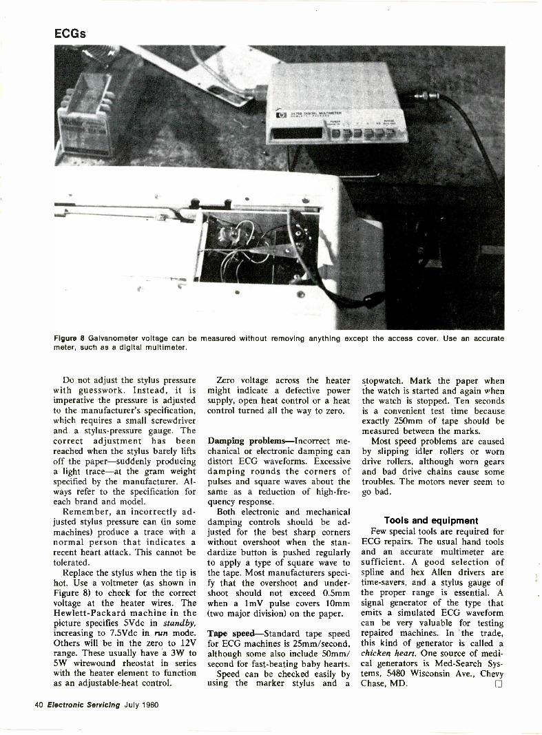
ECGs
Figure 8 Galvanometer voltage can be measured without removing anything except the access cover. Use an accuratemeter, such as a digital multimeter.
Do not adjust the stylus pressurewith guesswork. Instead, it isimperative the pressure is adjustedto the manufacturer's specification,which requires a small screwdriverand a stylus -pressure gauge. Thecorrect adjustment has beenreached when the stylus barely liftsoff the paper-suddenly producinga light trace-at the gram weightspecified by the manufacturer. Al-ways refer to the specification foreach brand and model.
Remember, an incorrectly ad-justed stylus pressure can (in somemachines) produce a trace with anormal person that indicates arecent heart attack. This cannot betolerated.
Replace the stylus when the tip ishot. Use a voltmeter (as shown inFigure 8) to check for the correctvoltage at the heater wires. TheHewlett-Packard machine in thepicture specifies 5Vdc in standby,increasing to 7.5Vdc in run mode.Others will be in the zero to 12Vrange. These usually have a 3W to5W wirewound rheostat in serieswith the heater element to functionas an adjustable -heat control.
Zero voltage across the heatermight indicate a defective powersupply, open heat control or a heatcontrol turned all the way to zero.
Damping problems-Incorrect me-chanical or electronic damping candistort ECG waveforms. Excessivedamping rounds the corners ofpulses and square waves about thesame as a reduction of high -fre-quency response.
Both electronic and mechanicaldamping controls should be ad-justed for the best sharp cornerswithout overshoot when the stan-dardize button is pushed regularlyto apply a type of square wave tothe tape. Most manufacturers speci-fy that the overshoot and under-shoot should not exceed 0.5mmwhen a lmV pulse covers 10mm(two major division) on the paper.
Tape speed-Standard tape speedfor ECG machines is 25mm/second,although some also include 50mm/second for fast -beating baby hearts.
Speed can be checked easily byusing the marker stylus and a
stopwatch. Mark the paper whenthe watch is started and again whenthe watch is stopped. Ten secondsis a convenient test time becauseexactly 250mm of tape should bemeasured between the marks.
Most speed problems are causedby slipping idler rollers or worndrive rollers, although worn gearsand bad drive chains cause sometroubles. The motors never seem togo bad.
Tools and equipmentFew special tools are required for
ECG repairs. The usual hand toolsand an accurate multimeter aresufficient. A good selection ofspline and hex Allen drivers aretime-savers, and a stylus gauge ofthe proper range is essential. Asignal generator of the type thatemits a simulated ECG waveformcan be very valuable for testingrepaired machines. In the trade,this kind of generator is called achicken heart. One source of medi-cal generators is Med-Search Sys-tems, 5480 Wisconsin Ave., ChevyChase, MD.
40 Electronic Servicing July 1980
fironexchanoeThere is no charge for a listing in Readers Exchange foritems "Needed," but we reserve the right to select andedit all copy. Due to the limited amount of space for thisdepartment, "Needed" listings must contain no more thanthree items. If you can help with a request write directly
to the reader, not to Electronic Servicing. "For Sale"listings will be charged for and included in the regularclassified section of Electronic Servicing. Please consultthat section for price and ordering instructions.
Needed:Vectorscope, Sencore ringer yoke and flybacktester, and B&K-Precision 1077B Analyst. Ken Miller,10027 Calvin St., Pittsburgh, PA 15235.
Needed: Old radio service literature. Old tube types,WD11's, 71, 112's 26, 45, 47, Dallas Swindal, 1112 SanJose Ln., Hanahan, SC 29406.
Needed:6AAJ8/ECH81 and 6DA6/EF89 tubes. James L.Bolich, 460 Doris Circle, Aberdeen, MD 21001.
Needed: Servicing information on Dressen Barnesdc -regulated power supply model 1K500B; DynamicInstrumentation microcomputer model 4132; TEK 291.J. Allen Call, 1876 E. 2990 So., Salt Lake City, UT84106.
Needed: Schematic for Seeburg AM/FM stereo modelSS40. A. Volovcin, 24 Mason St., Metuchen, NJ 08840.
Needed: Schematics for National Leisure Corporationof Anaheim, CA, video games. PC modules made bySix Pac (World Wide Video). E. Farker, 305 Main St.,Huntington Beach, CA 92468.
Needed: Schematic for Concord camera MTC12. Quoteprice. Ernest Jones, 810 W. Vernon Ave., Kingston,NC 28501.
Needed: Schematic for an old Westinghouse radiomodel WRK-275. Dan Grim, 9912 Mesa Arriba N.E.,Albuquerque, NM 87111.
Needed: Schematic and service data for Lowe-OptaFonovox Senator -Stereo type 532224 console stereosystem. Will buy, or copy and return. Jasper Baker,700 Lenox Ave., Apt. 21A, New York, NY 10039.
Needed: Schematic for Knight model KG -687 sweepmarker generator. Will buy or copy and return. MikeLarinoff, 5403 Cedar Creek, Houston, TX 77056.
Needed: Schematic for a Concord AM/FM stereoreceiver model MK -12. Will copy and return, or payfor copying. James E. Higley, 1460 Cypress Ave.,Hanover Park, IL 60103.
Needed: Sencore SG165 stereo Analyst, dual -tracescope, and other TV -stereo test equipment. Must be ingood working order with probes and manuals.Electronic Specialists, 1685 Edna Pl., Macon, GA31204.
Needed: A scope diagnostic unit and exhaust gasanalyzer for automobile engines. George Epstein,200-27 46th Ave., Bayside, NY 11361.
Put yourmoney where
your Heartis. 410
American
AssociationHeart
WE'RE FIGHTING FOR YOUR LIFE
July 1980 Electronic Servicing 41
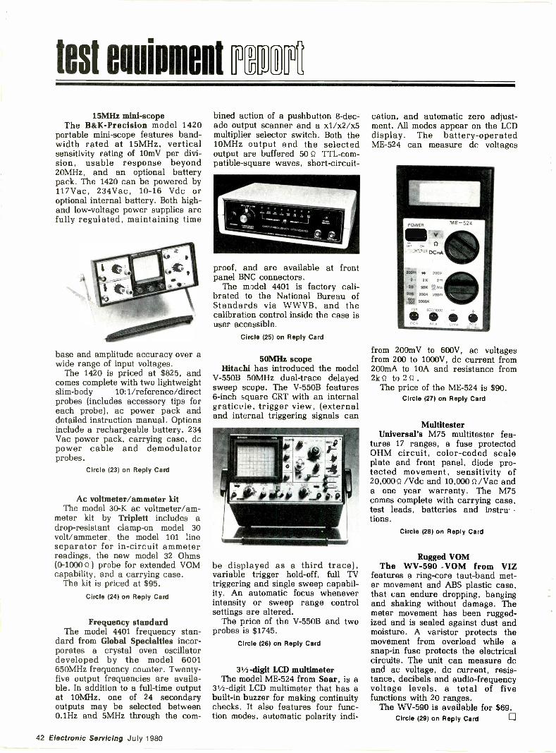
test mimeot n DO r15MHz mini -scope
The B&K-Precision model 1420portable mini -scope features band-width rated at 15MHz, verticalsensitivity rating of l0mV per divi-sion, usable response beyond20MHz, and an optional batterypack. The 1420 can be powered by117Vac, 234Vac, 10-16 Vdc oroptional internal battery. Both high -and low -voltage power supplies arefully regulated, maintaining time
base and amplitude accuracy over awide range of input voltages.
The 1420 is priced at $825, andcomes complete with two lightweightslim -body 10:1/reference/directprobes (includes accessory tips foreach probe), ac power pack anddetailed instruction manual. Optionsinclude a rechargeable battery, 234Vac power pack, carrying case, dcpower cable and demodulatorprobes.
Circle (23) on Reply Card
Ac voltmeter/ammeter kitThe model 30-K ac voltmeter/am-
meter kit by Triplett includes adrop -resistant clamp -on model 30volt/ammeter the model 101 lineseparator for in -circuit ammeterreadings, the new model 32 Ohms(0-1000 ) probe for extended VOMcapability, and a carrying case.
The kit is priced at $95.Circle (24) on Reply Card
Frequency standardThe model 4401 frequency stan-
dard from Global Specialties incor-porates a crystal oven oscillatordeveloped by the model 6001650MHz frequency counter. Twenty-five output frequencies are availa-ble. In addition to a full-time outputat 10MHz, one of 24 secondaryoutputs may be selected between0.1Hz and 5MHz through the com-
bined action of a pushbutton 8 -dec-ade output scanner and a xl/x2/x5multiplier selector switch. Both the10MHz output and the selectedoutput are buffered 50 Q TTL-com-patible-square waves, short -circuit -
proof, and are available at frontpanel BNC connectors.
The model 4401 is factory cali-brated to the National Bureau ofStandards via WWVB, and thecalibration control inside the case isuser accessible.
Circle (25) on Reply Card
50MHz scopeHitachi has introduced the model
V -550B 50MHz dual -trace delayedsweep scope. The V -550B features6 -inch square CRT with an internalgraticule, trigger view, (externaland internal triggering signals can
be displayed as a third trace),variable trigger hold -off, full TVtriggering and single sweep capabil-ity. An automatic focus wheneverintensity or sweep range controlsettings are altered.
The price of the V -550B and twoprobes is $1745.
Circle (26) on Reply Card
31/2 -digit LCD multimeterThe model ME -524 from Soar, is a
31/2 -digit LCD multimeter that has abuilt-in buzzer for making continuitychecks. It also features four func-tion modes, automatic polarity indi-
cation, and automatic zero adjust-ment. All modes appear on the LCDdisplay. The battery -operatedME -524 can measure dc voltages
POWER ME -524
Illo:.7.' 0 OConA
IWO 4* 200P
2 2K 2m
20 20K
202 TOOK zoom
2000K from 200mV to 600V, ac voltagesfrom 200 to 1000V, dc current from200mA to 10A and resistance from2k4 to 2 0 .
The price of the ME -524 is $90.Circle (27) on Reply Card
MultitesterUniversal's M75 multitester fea-
tures 17 ranges, a fuse protectedOHM circuit, color -coded scaleplate and front panel, diode pro-tected movement, sensitivity of20,000 Q /Vdc and 10,000 Q /Vac anda one year warranty. The M75comes complete with carrying case,test leads, batteries and instru -
tions.Circle (28) on Reply Card
Rugged VOMThe WV -590 -VOM from VIZ
features a ring -core taut -band met-er movement and ABS plastic case,that can endure dropping, bangingand shaking without damage. Themeter movement has been rugged-ized and is sealed against dust andmoisture. A varistor protects themovement from overload while asnap -in fuse protects the electricalcircuits. The unit can measure dcand ac voltage, dc current, resis-tance, decibels and audio -frequencyvoltage levels, a total of fivefunctions with 20 ranges.
The WV -590 is available for $69.Circle (29) on Reply Card
42 Electronic Servicing July 1980
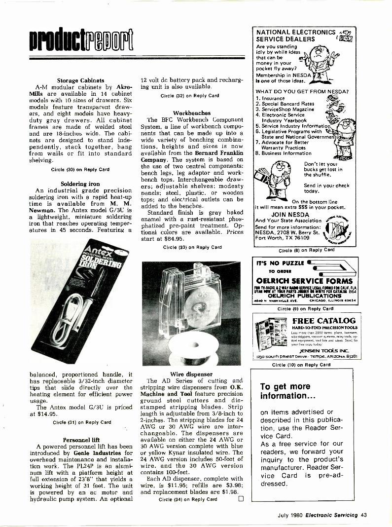
Storage CabinetsA -M modular cabinets by Akro-
Mills are available in 14 cabinetmodels with 10 sizes of drawers. Sixmodels feature transparent draw-ers, and eight models have heavy-duty gray drawers. All cabinetframes are made of welded steeland are 18 -inches wide. The cabi-nets are designed to stand inde-pendently, stack together, hangfrom walls or fit into standardshelving.
Circle (30) on Reply Card
Soldering ironAn industrial grade precision
soldering iron with a rapid heat -uptime is available from M. M.Newman. The Antex model G/3U isa lightweight, miniature solderingiron that reaches operating temper-atures in 45 seconds. Featuring a
balanced, proportioned handle, ithas replaceable 3/32 -inch diametertips that slide directly over theheating element for efficient powerusage.
The Antex model G/3U is pricedat $14.95.
Circle (31) on Reply Card
Personnel liftA powered personnel lift has been
introduced by Genie Industries foroverhead maintenance and installa-tion work. The PL24P is an alumi-num lift with a platform height atfull extension of 23'8" that yields aworking height of 31 feet. The unitis powered by an ac motor andhydraulic pump system. An optional
12 volt dc battery pack and recharg-ing unit is also available.
Circle (32) on Reply Card
WorkbenchesThe BFC Workbench Component
System, a line of workbench compo-nents that can be made up into awide variety of benching combina-tions, heights and sizes is nowavailable from the Bernard FranklinCompany. The system is based onthe use of two central components:bench legs, leg adaptor and work-bench tops. Interchangeable draw-ers; adjustable shelves; modestypanels; steel, plastic, or woodentops; and electrical outlets can beadded to the benches.
Standard finish is gray bakedenamel with a rust -resistant phos-phatized pre -paint treatment. Op-tional colors are available. Pricesstart at $84.95.
Circle (33) on Reply Card
Wire dispenserThe AD Series of cutting and
stripping wire dispensers from O.K.Machine and Tool feature precisionground steel cutters and die -stamped stripping blades. Striplength is adjustable from 3/8 -inch to2 -inches. The stripping blades for 24AWG or 30 AWG wire are inter-changeable. The dispensers areavailable on either the 24 AWG or30 AWG version complete with blueor yellow Kynar insulated wire. The24 AWG version includes 50 -feet ofwire, and the 30 AWG versioncontains 100 -feet.
Each AD dispenser, complete withwire, is $11.95; refills are $3.98;and replacement blades are $1.98.
Circle (34) on Reply Card Fj)
NATIONAL ELECTRONICS .(<)9SERVICE DEALERS (XVAre you standingidly by while ideasthat can bemoney in your -pocket fly away?Membership in NESDAis one of those ideas.
WHAT DO YOU GET FROM NESDA?1. Insurance2. Special Bancard Rates :/.../.---'3. ServiceShop Magazine 7/
v.,4. Electronic Service t\':'
Industry Yearbook .,-c=5. Service Industry Informatio i"'6. Legislative Programs with il 'Iltrh.
State and National Governmenj, I
7. Advocate for Better 410'8. Business Information IV.Warranty Practices
Don't let yourbucks get lost inthe shuffle.
Send in your checktoday.
On the bottom lineit will mean extra $$$ in your pocket.
JOIN NESDANst.o.'"utAnd Your State Association
Send for more information: 4NESDA, 2708 W. Berry St.Fort Worth, TX 76109
Circle (8) on Reply Card
IT'S NO PUZZLETO ORDER
OELRICH SERVICE FORMSFOR TV-RA010 i 2 WAY RAMO SERVICE LEGAL FORMS FOR CALIF. FLA.UTAH NOW AT YOUR PARTS JOBBER OR WRITE FOR CATALOG 864
OELRICH PUBLICATIONSA040 N NASHVILLII AV[. CHICAGO. ILLINOIS 60634
Circle (9) on Reply Card
FREE CATALOGHARD -TO -FIND PRECISION TOOLS
Lists more than 2000 iterns. pliers, tweezers,wire strippers, vacuum systems. relay tools, op-tical equipment, tool kits and cases. Send foryour free copy today!
JENSEN TOOLS INC.1230 SOUTh PRIEST DRIVE TEMPE. ARIZONA 85281
Circle (10) on Reply Card
To get moreinformation...
on items advertised ordescribed in this publica-tion, use the Reader Ser-vice Card.As a free service for ourreaders, we forward yourinquiry to the product'smanufacturer. Reader Ser-vice Card is pre -ad-dressed.
July 1980 Electronic Servicing 43
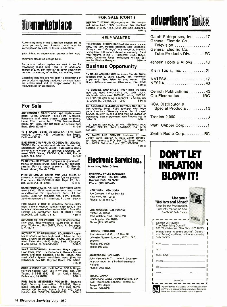
nmarketalace
Advertising rates in the Classified Section are 35cents per word, each Insertion, and must beaccompanied by cash to Insure publication.
Each initial or abbreviation counts a full word.
Minimum classified charge $3.00.
For ads on which replies are sent to us forforwarding (blind ads), there is an additionalcharge of $3.00 per Insertion to cover departmentnumber, processing of replies, and mailing costs.
Classified columns are not open to advertising ofany products regularly produced by manufactur-ers unless used and no longer owned by themanufacturer or distributor.
For SaleAUTOMOBILE RADIO and tape replacementparts: Delco, Chrysler, Philco-Ford, Motorola,Panasonic and many others. Large Inventory.Laran Electronics, Inc., 3768 Boston Road,Bronx, NY 10469, (212) 881-9600, out of New YorkState, (800) 223-8314. 5-79-tf
TV & RADIO TUBES, 36 cents EA!! Free colorcatalog. Cornell, 4221 University, San Diego,Californai 92104. 8-76-tf
ELECTRONIC SURPLUS: CLOSEOUTS, LIQUIDA-TIONS! Parts, equipment stereo, Industrial,educational. Amazing values! Fascinating Itemsunavailable In stores or catalogs anywhere. Un-usual FREE catalog. ETC0-011, Box 762, Platts-burgh, N.Y. 12901. 6-78-tf
TV RENTAL SYSTEMS! Complete & guaranteed.Manual or computerized. Send $2.00 for completedetails. Perry's rental systems, 133 BrendaStreet, Milton, Florida 32570. 2-80-tfn
PRINTED CIRCUIT boards from your sketch orartwork. Affordable prices. Also fun kit projects.Free details DANOCINTHS INC. Dept. ES, Box261, Westland, MI 48185. 5-80-8t
SAMS PHOTOFACTS 775-1808; New tubes worthover $3300; ECG semiconductors and othermiscellaneous TV replacement parts. All for$2500. Send for complete list. Barry Bassett,2910 Williamsburg St., Sarasota, FL 33581.6-80-2t
FOR SALE: 2 MCF-80 diffusion pumps-$325each, 2 Welsh vacuum pumps-$450 each, 1 twotube Marinate oven w/controls-$400, 1 ScientificElectric Co. Bombarder-$500. R. KOCH, 1363ILLINOIS, LASALLE, IL 61301. 7-80-1t
SCRAMBLED TELEVISION, encoding/decoding.New book. Theory/circuits-$9.95 plus $1 ship-ping. Workshop, Box 393ES, Dept. A, Bethpage,N.Y. 11714. 7-80-tf
PICTURE TUBE REBUILDING EQUIPMENT capa-ble of producing four high quality tubes per day(WILL TRAIN TO OPERATE)-$4200. Call or writeAtoll Television, 6425 Irving Park, Chicago,Illinois 60634, ph. 312-545-6667. 7-80-2t
SAVE HUNDREDS: American Made qualityHead -Ends, V/V, U/V Converters, Camera Modu-lators. Mid -band available. Factory Prices. Alsosmall CAN System amplifiers. Send $5.00 (orletterhead). Box 809, Boynton Beach, Fla. 33435.
7-80-tf
CODE A PHONE 410, built before FCC & RingerWs were needed. Can't use in my area-$65. JeffYoust, 215-868-8992, 531 W. Union Blvd.,Bethlehem, PA 18018. 7-80-11
FOR SALE: SEVENTEEN VOLUMES, SupremeRadio Servicing information, 1926-1957, MasterIndex included. Make offer. Will ship U.P.S.Arnolds CB Service, Route 2, Box 673, CasaGrande, Ariz. 85222, Ph. 02-836-0299. 7-80-1t
FOR SALE (CONT.)HEATHKIT ET3400 Microcomputer. Six monthsold. Assembled. 100% functional. See Heathkitcatalog. $189.00 f.o.b. (317) 348-4952 evenings.
7 80 1 t
HELP WANTED
TELEVISION TECHNICIANS-Experience neces-sary, top pay, medical benefits, paid vacations.Enjoy a new "Life Style" in a beautiful, friendly,smog free, full service desert community. Sendyour resume to 225 E. Ridgecrest Blvd., Ridge -crest, California 93555. Telephone 714-375-1361ask for Service Manager. 3-80-tfn
Business OpportunityTV SALES AND SERVICE in sunny Florida. Samelocation over 20 years. $20,000 firm. Interestedapply only. Send letter to shop owner, 1516South Jefferson Avenue,. Clearwater, Fla. 33516
3-80-5t
TV SERVICE AND SALES INVENTORY includesnew and used merchandise and parts stock,wholesale value over $8000.00, asking 3500.00.Call 302-846-9793 or write Johnny's TV Clinic, 605E. Grove St., Delmar, Del. 19940 6-80-1!
ESTABLISHED TELEVISION SERVICE CENTER InSan Antonio, Texas. Fully equipped with largeparts Inventory. Warranty station for 6 majorbrands. Custom built building may be leased orpurchased. Lots of potential. Jack Trudeau-(512)349-4101. 7-80-1t
T.V. SALES SERVICE, 30 yrs. RETIRING RCAZENITH DEALER, SAN LEANDRO, CA. (415)357-9888. 7-80-1t
TV SALES AND SERVICE business in NewJersey. Same location 20 years. Zenith distribu-tor. Send letters to P.O. Box 713, South Amboy,N.J. 08879. Call after 6 pm. (201) 566-3366.
7-80-2t
Electronic Servicing ®
Advertising Sales Offices
NATIONAL SALES MANAGERGreg Garrison, P.O. Box 12901,Overland Park, KS 86212;Phone: (913) 888-4884
NEW YORK, NEW YORKJoe Concert, 4 West 58th St.,New York, NY 10019;Phone: (212) 888-1977
LOS ANGELES, CALIFORNIAHerbert A. Schiff3055 Wllshrle Blvd., Suite 350Los Angeles, CA 90010Phone (213) 387-0639
LONDON, ENGLANDJohn Ashcraft & Co., 12 Bear St.,Leicester Square, London, WC2H 7AS,England;Phone: 930-0525Telex: 895-2387
AMSTERDAM, HOLLANDJohn Ashcralt & Co., John J. lucassen,Akerdijk 150A, 1171 PV-BadhoevedorpHolland;Phone: 2968-6226
TOKYO, JAPANInternational Media Representatives, Ltd.,2-29, Toranomon 1-chome, Minato-ku,Tokyo 105, Japan;Phone: 502-0656
a verhsers
Gamit Enterprises, Inc. 17General Electric Co.,
Television 7General Electric Co.
Tube Products Div IFC
Jensen Tools & Alloys 43
Klein Tools, Inc 21
NATESA 17NESDA 43
Oelrich Publications 43Ora Electronics IBC
RCA Distributor &Special Products 13
Tronics 2,000 3
Wahl Clipper Corp 1
Zenith Radio Corp. BC
p
DON'T LETINFLATIONBLOW IT!
Use your"Dollars and Sense"Send for this free booklet,
and information on howto obtain bulk copies.
George W. HaydenThe Advertising Council825 Third Avenue, New York, N.Y. 10022Please send me a free copy of "Dollarsand Sense: and information for orderingbulk copies.
NAME
TITLE
ORGANIZATION
STREET
OTT
STATE ZIP
SIGNATURE
L JA public service message of The Advertising Counciland The U.S.Departments of Agriculture. Commerce.
ark, Labor and Treasury Presented by this magazinep
44 Electronic Servicing July 1980
11.
TheProfessional'sChoiceTest equipment, primegrade original replace-ments, chemicals, tapeheads .. . and MORE!
ELECTRONICSA DIVISIONOF ALLIANCERESEARCH CORPORATION
7241 CANBY AVE. RESEDA, CALIFORNIA 91335
or
.41
-0051449 7,at5i
We feature only quality test equipment: Leader Instruments, Hitachi, Beckman,
Hickok, and others. ,2,y I
1
Leader LB0515B Hitachi V-302 Beckman 330 Hickok LX 304
SPECIALOFFERA top quality 30 Mhz, dual trace,trigged oscilloscope with 1 mV
sensitivity and delay line.FOR UNDER $800.001 (including 2 probes)
Limited to professional technicians,engineers, and members of the trade. Call infor details and complete specifications.
SHIPPED THE SAME DAY SHIPPED THE SAME DAYSENDUST ALLOY HEADSMetal tape compatible!Standard configuration stereo: 1 SENDUST ALLOY
$13.50 A5-2 AUTO REVERSE
Longer life. HEADS
Best frequency response. As3 $20.00 ea.
TAPE HEADSPERMALLOY HEADS WYR32
Cassette stereo
$4.50
,
WY435 WY488
PERMALLOYAUTO REVERSE
HEADS
$7.00
WY802 WY8228PE 21
HIGH QUALITY TEST CASSETTESPTC 1 Level Test (-10 dB)
FTC 2 S/N Ratio (0 d8)PTC 3 Speed Test (3000 Hz)
PTC 4 Head Alignment
PTC 5 Frequency Response
CT 120 Torque Meter
of.. eu0t!
ORIGINAL JAPANESE REPLACEMENT PARTS IN STOCK!
AIR CORE INDUCTOR
(for crossover network)20 AWG Wirel.28 mH 1.60
1.0 mH 2.75
1.8 mH
1.86
3.36
25 mH 425
Build your own speaker system!
CROSS OVERNETWORKS
4 ohms or 8 ohms - Made withAIR CORE COILS or FERRITECORE. Many to choose from.Example: NT406H crossover net-work: 100 watts input! 3 way, allair core construction for lowestdistortion.
ONLY
$9.00 ea.
CRYSTALS
1-11 $3.50 ea.12 -up $3.00 ea.
20 pF Load Impedance'7.0025 MHZ7.7975 MHZ
10.240 MHZ10.695 MHZ11.1125 MHZ
11.2858 MHZ
11.3258 MHZ11.2850 MHZ
11.2842 MHZ
11.240 MHZ11.730 MHZ36 570 MHZ
NON POLARIZEDELECTROLYTICCAPACITORS
For crossover use (axial lead)
offil 1-11 *Ai I11
1/100 .50 14/100 60
2.2/100 .50 16/100 65
32/100 .55 22/100 .70
4.7/100 .55 33/100 .95
6.8/100 .55 47/100 120
8.0/100 .60 100/100 1.65
10/100 60 150/100 25512/100 60 299/100 3.00
I.C.s - Prime GradeThese prices are for 1-11 qty!
Call for better price quotes.
AN 306
AN 318
AN 7130
AN 7150
AN 7156N
BA 1310
BA 1320
DA 101
HA1366W
HA1368
HA1377A
HA1457
LA1368
LA1460
LA3155
LA3160
LA3201
LA4032P
LA4051P
LA4420
LA4430
LA5110
LB1331
M53273
MB3705
M83712
MB3756
MB8719
S -40W
S -60W
S-100WA
5-200W
SM5104
STK0029
STK0039
STK0050
STK011
STK013
We sell exclusively to professionals andmembers of the trade. Minimum order 525.00.We pay shipping and insurance on pre -paidorders in the continental U.S.A.
C.O.D. orders, VISA/ MasterCard welcome!
VCR Chroma
VCR ServoPower Amp.
Power Amp.
BTL Amp.
PLL Demod.
PLL MPX Demod.
Delco DM98Power Amp
Power Amp
20 Watts AmpL.N. PreampChroma Processor
Deflection CKT
EqualizerPreamp
Mini Preamp3W Amp2.5W Amp
5.5W Amp
4.5W Amp
RegulatorVIR Sig. Processor
VCO for CB
4.5W Amp
5.0W Amp
SIL RegulatorProgrammable PLL
40W Amp
60W Amp
100W Amp
200W Amp
PLL CircuitDarlington HY8Darlington HYBDarlington HYBHybrid E5W AmpHybrid 15W Amp
1200
9.00
3.00
3.25
4.00
3.50
3.50
TOD
2.80
2.80
4.90
1.80
3.50
4.50
1.80
1.60
1.50
2.25
2.50
2.50
2.85
2.00
E501.00
3.00
3.85
3.50
7.50
13.90
17.90
27.90
45.25
9.00
6.00
7.10
8.90
4.50
13.50
I.C.s - Prime GradeContinued
STK040 Dual 10W Amp 12.00
STK415 2 Ch. Hybrid Amp 9.00
TA7109AP Amplifier 5.00
TA7205AP BTL Amp 2.50
TA7217AP 5.8W 4 ohms amp 4.25
TA7222P 5.8W Amp 3.80
TA7227P BTL Amp 7.00
TA7312P L.N. Preamp 2.00
TC9106P C.B. PLL 7.00
UPC671C Amp 5.00
UPC1181H BTL Amp 3.50
UPD857C Ham PLL 7.80
UPD858C C.D. PLL 6.50
UPD2815 Freq. Synth. 12.50
UP02816 Freq. Synth. 12.50
Plus more 1.C.s atsame low price.
Ask for ourquantity discount!
"OurServiceMakes
TheDifference"Free Catalog to the Trade.
All Others $1.00 ea.
TRANSISTORS- Prime Grade
These prices are for 1-11
25A509 .50
2SA606 1.45
25A684 .60
2SA699A .80
25A912 .80
2SA912 .90
25A917 1.80
2SA981 8.00
258471 2.00
2S8507 1.50
258555 4.60
258618 3.00
2S8681 5.75
258688 3.30
2S8700 4.00
25E754 3.75
2SC281 .6o
2SC937 8.50
25C1111 5.20
2SC1209 1.50
25C1964 3.00
25C1942 4.50
2SC2001 .50
2SC2086 .60
25C2101A 11.95
25C2103A 15.00
2SC2166 2.00
25091 1.90
25D425 3.50
250588 3.00
25D712 1.20
25D725 6.50
25D870 7.50
250870 7.50
250903 6.50
MRF454 22.00
MRF455 15.95
MRF901 3.20
PLUS MANY MORE,
TO ORDER, CALL TOLL -FREE:(800) 423-5336 In Calif. (800) 382-3663
Local (213) 705-0022 Telex 181011
Circle (1) on Reply Card
a.
Switch toZENITH UNIVERSAL TRIPLERS
and get more than just a tripler...get a complete package.
A95-5314 977-29500-A
ECG 500A 977-Z9500 AECG 521 800-791
ECG 522 977-Z9522ECG 523 977-36
ECG 526A 977 -Z9526 -A
ECG 528 977-41
ECG 529 977-Z9529ECG 530 977.29530ECG 531 977-Z9531
ECG 532 977.29532ECG 533 977-Z9533ECG 534 977-29534
ECG 535 977-29535ECG 536A 977 -Z9536 -A
ECG 537 977-Z9537ECG 538 977-29538ECG 539 977-Z9539
GE 521 977 -Z9526 -A
GE 522 977 -Z9536 -A
GE 523 977-Z9522GE 524 977-29531GE 525 977-29532GE 526 977-Z9533GE 527 977 -Z9500 -A
GE 528 977-36
GE 529 977-Z9529GE 534 977-Z3534GE 535 977-Z9535GE 536 977-Z9537GE 537 97? -29538
GE 538 977-29539GE 539 800-791
GE 540 977.Z9530
N2A 917-Zt-I!Oz9
N2A-1 977-29529
N2A-2 977-Z9529
SK 3301
SK 3302SK 3303
SK 3304
SK 3305
SK 3306
SK 3307SK 3308
977-Z9531
977-Z9533
977-Z9522977-29500-A977-Z9534977-36
977-Z9529977.29526-A
148348-1
1413348.2
148348-31413348-4
148348-5
977-36977.36
977.36977-36
977-36
28-32-0X 977.29500-A28-35-01 977.46
32-29778-2 977-29500-A32-29778-3 977-29500-A32-33057-2 977.29522
32-33057-3
32-33057-432-33057-5
977 -Z9500 -A
977 -Z9500 -A
977-29500-A32-33094-1
32-33094,2
32.33094-3
32-33094-4
32-33094-5
977-Z9522
977-Z9522
977-Z9522
9'11.29522
977-Z9522
32-33094-6 977-29522
32.35894-1 977 -Z9500 -A
32-35894-3 977.29522
32-35894-4 977-Z9522
32-35894-5 977-29500-t32-35894-6 977-29522
32.35894-732.39091-1
32-39091.2
32-39091.3
32-39091-432-39091-532-39091-6
32-39091-7
32-39091-8
977-295;977.36
977-36
977-Z95.977-36977-36
977-36
977 -Z9526 -A
977 -2952b -A
32.39091-932-39704-1
32-39704-2
977-36
977-Z9522977-Z9522
66F-159-1
66F-159-2
66F 159-3
66X0060-(
66X0060-C.N
76-14327-1
76-14327-2
76-14327
7E
0,8500.--
06-3
127-'
.3
530165-4
'165-665-8
977-Z9522
977-29522
977-Z9530
77-29530
977-36
977-29522
977-29t,22
977-29522977.29522977 1,.9522
977.29529977-Z9534
34
29
29
35
34
14
!r.-3
5
977-Z9522977 Z9522
Now in stock at , your Zenith distributor's -a full line of universal triplets.
Packaged with each Zenith -.ripler is a cross-referenceguide with a no-nonsense numpering system that relates ECG,GE, and RCA Universal lines and 22 other manufacturers toZenith part numbers...plus detailed installation and safetyinstructions...and a wire tie and sealant at no extra cost.
That's why you get more than just a tripler when you switchto Zenith Universal Triplets.
See your distributor for Zent-i's Universal Tripler CrossReference Guide (#902-2011).. and Zeniths UniversalSemiconductor Guide with over 150,000 cross-references!
ECG is a registered tradernarIr of GTE SYLVANIA7..41.111.111°The qua ity g Des in before the name goes on''
Zenith Radio Corporation I Sery ce, Parts & Accessories Division11000 Seymour Avenue / Franklin Park, Illinois 60131
93D96-257-90 977-Z953057-98 977-29533 93096-3
93D99-2
66F-054-3 977 -Z9500 -A931399.3
93099-466F -054-4 977-29500-A66F-112-1 977 Z9522
93099.593099-6
66F-112.2 977-Z952266F-181-1 977-Z9522
931399-7
800-000-025
97' -Z9500 -A
0/1-29500-A977-29538977-29538977-Z953897'-29539977-2953997'-29539
9 r.Z9E00-A
72180 977-36
146364-1
1464607-1
1464607.21464607-3
1464607.41464607.5
977 -Z9536 -A
977.Z9532977-Z9532
977.29532977-29532
977-A9532
1464607-6 977-Z95321464607-7 977-Z95311464607-8 977-Z9531
1464607-9 977-Z95331464607-10 977-Z95331464984-1 977-Z95321464934-2 977-Z95321466860-1 977-Z95321466860.2 977-Z95371466865.1 977-Z9532
1826065-1 977-Z95321826065-2 977-295321826065-3 977-29531
S-88569 800-791
S-88593 800-791
S-91731 800-791
212.102 800-791
212-103 800-791212-104 800-791
212-105 800-791
212-106 800.791212-108 800-791212.109 800-791212-110 800-791
212-128 800-791212-129 800-791212-130 800-791
212-131 800-791
212-132 800-791212-133 800-791
212-134 800-791212-135 800-791
212-136 800-791212-137 800-791
212-138 800-791
212-140 800 791
212-140-01 800-791212-141 977-36
212-141 977-36212 141 01 977-36212 141 01 977-35
212 141 01 977-36212-141-01 977-36212-141-02 977-36
212-141-02 977-36212-141-03 977.37212.142 977.46212-142 977.38212-142-02 977-46212.143 977.40212-145 977.41212-145-01 977-41
212.145.01 977-42212-146 977.41
212-146-01 977.41212-146.01 977-42212-147 977.43212-149 977.45977.42 977-41
Circle (2) on Rep y Card4.4.