For Induction Motor Control - us
3
44 For Induction Motor Control , The command speed has an'S' form, typical in vertical operation systems. The reason I for this command speed is that a soft acceleration/deceleration avoids abrupt movements in the elevator cabin, increasing the comfort level. J.L. Mora, F. Barrero, E. Galvan, F. Colodro, J.N. Tombs, M. Barranco*, A. Torralba and L.G. Franquelo; Dpto. de Ingenierfa Electronica, Escuela Superior de Ingenieros, Sevilla Spain Ajuzzy-logic based controller jor the speed and position control I t is well known that high performance speed regulation of an induction machine requires vector control. By means of a coordinate transformation of measured currents, we can obtain two new current components directly related with the flux and torque of the machine, so we can control the induction motor as a sep- arately excited DC machine. The angle that defines this coordinate transformation must be estimated using the dynamic modelling of the Olud I '1' machine which requires a proper knowledge of the rotor time constant. The operations that must be performed for a vector control algorithm are nowadays imple- mented in a microprocessor, usually a DSP. This '0' J Vector L Control ! S ...... it.che programmable bits and state of them PCIM Europe May 2002
Transcript of For Induction Motor Control - us

44
For Induction Motor Control ,
The command speed has an'S' form, typical in vertical operation systems. The reason I
for this command speed is that a soft acceleration/deceleration avoids abrupt
movements in the elevator cabin, increasing the comfort level. J.L. Mora, F. Barrero, E.
Galvan, F. Colodro, J.N. Tombs, M. Barranco*, A. Torralba and L.G. Franquelo; Dpto. de
Ingenierfa Electronica, Escuela Superior de Ingenieros, Sevilla Spain
Ajuzzy-logic based controller jor the speed and position control
It is well known that high performance speed
regulation of an induction machine requires
vector control. By means of a coordinate
transformation of measured currents, we can
obtain two new current components directly
related with the flux and torque of the machine,
so we can control the induction motor as a sep
arately excited DC machine. The angle that
defines this coordinate transformation must be
estimated using the dynamic modelling of the
Olud I
'1'
machine which requires a proper knowledge of
the rotor time constant.
The operations that must be performed for a
vector control algorithm are nowadays imple
mented in a microprocessor, usually a DSP. This
'0'
J
Vector L Control !
S ...... it.che programmable bits and state of them
PCIM Europe May 2002
LGF
Texto escrito a máquina
Integrated Solution for Induction Motor Control

The operations that
must be performed
for a vector control
algorrrhm are nowadays
implemented in a
microprocessor,
usually a DSP
solution is expensive in development cost, so a with a highly accurate speed and torque con-
specific chip that could perform all the functions trol, especially in low speed operation range.
required can be an interesting solution.
This article presents an ASIC, named
ASITRON that integrates all the logic required
for high performance control of induction
motors. The ASIC is part of a compact indus
trial control system for elevators build by
Macpuarsa Company (figure 1). In elevator
industry, motors are used in a particular way:
the motor is operated from zero speed to nom
inal positive or negative speed and then put
back to zero, while positive or negative torque
loads are applied.
This functional operation is accomplished due
to ASITROI'J.
ASrmON, figure 2, integrates the indirect vec
tor control algorithm, a digital tachometer, a 64-
rules built-in fuzzy logic based controller for
speed and position regulation, ~ PWM based
current controller and a set of ext&naJ interfaces,
such as AID converters for current measure
ments and a microprocessor parallel interface.
Figure 3 depicts a block diagram of the ASIC,
including its programmability. Notice that it can
perform a 3-phase PWM current or vo~age gen-
speed and position regulation.
The comfort feeling of passengers is related erator, a classical voltage-frequency controller
The indirect vector control algorithm, the
coordinate change and the current control loop
have been implemented using a 13-bits multi
plier and an 18-bits adder. Three inputs, the
command torque current (obtained from the
fuzzy controller), the flux current reference and
the mechanical speed (obtained from a speed
measurement block) are used to determine the
electrical angle, needed for coordinate transfor
mation, and to obtain the reference currents,
necessary for the inner current control loop, fig
ure 4. ~ ... .J ... J
--- ... --- ----- ... _-,. ... ;-
Ton FREO T+!·
, .. r,
or to implement a modem vec
torial control of the induction
motor with a fuzzy-logic based
MUX
NPUT,
R.IlM (32x4x12)
bas I---c--'-T----oo-i
Moreover, the current control loop is based
CT1
SOT,
CT2 de5ired output
f------'--+I DE FUZZIFIER
I I
I CT1 CT2 1 I 1 I 1 1 1 1- ___________ -0- _______ ~_G.!.,_ - - - - - - - - __ ...!
Integrated Solution For Induction Motor Control continues
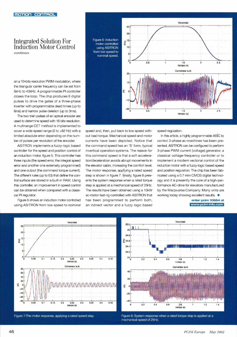
on a 10-bits resolution PWM modulation, where
the triangular carrier frequency can be set from
5kHz to 43kHz. A programmable PI controller
closes the loop. The chip produces 6 digital
pulses to drive the gates of a three-phase
inverter with programmable dead times (up to
6ms) and narrow pulse deletion (up to 3ms).
The two train pulses of an optical encoder are
used to determine speed with 16 bits resolution.
A multirange CET method is implemented to
cover a wide speed range (0 to ±82 Hz) with a
limited absolute error depending on the num
ber of pulses per revolution of the encoder.
ASITRON implements a fuzzy-logic based
controller for the speed and position control of
an induction motor, figure 5. This controller has
three inputs (the speed error, the integral speed
error and another one externally programmed)
and one output (the command torque current).
The drfferent rules (up to 63) that define the con
trol surface are stored in a built-ill RAM. Using
this controller, an improvement in speed control
can be obtained when compared with a classi
cal PI regulator.
46
Figure 6 shows an induction motor controlled
using ASITRON from low speed to nominal
0.05 0.1 0.15 0.2 0.25 0.3 1"",pO (S)
CoHtentes la .10
speed and, then, put back to low speed with
out load torque. Mechanical speed and motor
currents have been depicted. Notice that
the command speed has an'S' form, typical
invertical operation systems. The reason for
this command speed is that a soft accelera
tion/deceleration avoids abrupt movements in
the elevator cabin, increasing the comfort level.
The motor response, applying a rated speed
step is shown in figure 7. I}inally, figure 8 pres
ents the system response when a rated torque
step is applied at a mechanical speed of 25Hz.
The results have been obtained using a 10kW
ac-motor test-rig controlled with ASITRON that
has been programmed to perform both,
an indirect vector and a fuzzy logic based
24.4
24.2
0.35 0.4 0.45 24
0 0.2
40
speed regulation.
In this article, a highly programmable ASIC to
control 3-phase ac-machines has been pre
sented. ASITRON can be configured to perform
3-phase PWM current (voltage) generator, a
classical voltage-'frequency controller or to
implement a modern vectorial control of the
induction motor with a fuzzy-logic based speed
and position regulation. The chip has been fab
ricated using a 0.7 mm CMOS digital technol
ogy and it is presently the core of a rligh-per
formance AC-drive for elevators manufactured
by the Macpuarsa Company. Many units are
working today showing excellent results. •
enter pcim 10664 at www.pcim-info.com
PCIM Europe May 2002