
For Husqvarna Parts Call 606-678-9623 or 606-561-4983
48
101 89 11-26 Rider 850, Rider 970, Rider 850 HST, Rider 970 HST, Rider 1030 Bioclip, Rider 1200 Workshop Manual For Husqvarna Parts Call 606-678-9623 or 606-561-4983 www.mymowerparts.com
Transcript of For Husqvarna Parts Call 606-678-9623 or 606-561-4983

101 89 11-26
Rider 850, Rider 970,Rider 850 HST, Rider 970 HST,Rider 1030 Bioclip, Rider 1200
Workshop Manual
Eng-Verk Riders front 97-04-29, 09.471
For Husqvarna Parts Call 606-678-9623 or 606-561-4983
www.mymowerparts.com

English – 1
Safety regulations ...............................................2General instructions ........................................ 2Special instructions ......................................... 2
Special tools ........................................................3Technical data .....................................................4
Dimensions.......................................................4Engine .............................................................. 4Gear box ..........................................................4Transmission ....................................................4Control points ...................................................4Play .................................................................. 4Tightening moments ........................................ 4
Delivery measures ...............................................5Measures before delivery ................................ 5
Fastening steering wheel ........................... 5Fastening seat .............................................5Fastening support wheels .......................... 6Fastening safety guard ............................... 6Refilling battery acid ................................... 6
Design and function .......................................... 7General ............................................................7Engine .............................................................. 8Steering ............................................................9Driving ............................................................ 10Mowing deck .................................................. 11
Reparation instructions ................................... 12Removing engine ...........................................12Replacing engine ............................................14Checking and adjusting steering wires .......... 17Replacing steering wires ............................... 18Removal/installation of steering axle ............. 18Removal/installation of wire wheel ................ 19Checking and adjusting brake wire ................ 20
Checking and adjusting Rider 850/970 ..... 20Checking and adjusting Rider1030 Bioclip/1200 ..................................... 20
Checking and adjusting gear controlRider 850/970 .................................................21Checking and adjusting throttle controlRider 1030 Bioclip/1200 ................................ 21Checking and adjusting freewheel clutchRider 850/970 .................................................22Replacing articulated steering bearing .......... 22
Removal of swing axle .................................. 24Installation of swing axle ............................... 24Removal/installation of gear box ................... 25Removal/installation of hydrostatic transmissionRider 850 HST/970 HST ............................... 26Removal/installation of hydrostatic transmissionRider 1030/1200 .............................................27Replacing hydrostat. trans. axle seals ........... 29
Ingoing axle ...............................................29Outgoing axles ..........................................30
Hydrostatic transmission brake ..................... 31Removal of brake ..................................... 31Installation of brake .................................. 31Adjustment of brake ................................. 32
Bleeding hydrostatic transmission oil system 33Adjustment of transmission neutral position .. 33Transmission maintenance ............................ 34
Oil change .................................................34Ineffective brake power ............................ 34
Checking and adjusting cutting unit ground .......pressure Rider 970/1030 Bioclip/1200........... 35Checking and adjusting parallelism of the .........mowing deck ..................................................35
Adjusting Rider 1030 Bioclip/1200 ............ 35Adjusting Rider 850 .................................. 36Adjusting Rider 970 .................................. 36
Adjusting cutting height area ......................... 36Removal of mowing deck Rider 1030and Rider 1200 ...............................................37Removal of mowing deck Rider 970 .............. 37Removal of mowing deck Rider 850 .............. 38Replacing cutting unit belts ........................... 38
Belt replacement on bioclip-unit ............... 38Belt replacement on mowing deck with side-or rear discharge ...................................... 39
Removal of blades with bearings ................... 40Grinding and balancing of blades .................. 41
Electrical system ...............................................42Circuit diagram Rider 850 .............................. 42Circuit diagram Rider 970 .............................. 43Circuit diagram Rider 850/970 HST............... 44Circuit diagram Rider 1030 Bioclip/1200 ....... 45
Workshop manualRider 850, Rider 970,
Rider 850 HST, Rider 970 HST,Rider 1030 Bioclip, Rider 1200
Contents
Eng-Verk Riders 97-04-28, 16.461
For Husqvarna Parts Call 606-678-9623 or 606-561-4983
www.mymowerparts.com

2 – English
Safety regulations
General instructions
The workshop handbook is written for personnel whoare assumed to have general ride-on mowerreparation and service know-how.
The workshop where the ride-on mower is repairedshould be equipped with safety devices inaccordance with local regulations.
No-one should attempt to repair the ride-on mowerwithout having first read and understood the contentsof this handbook.
The machine is tested for safety and approved onlyfor equipment supplied or recommended by themanufacturer.
The below-mentioned boxes are included in thisworkshop handbook, as is appropriate.
Special instructions
The fuel used in the ride-on mower has thefollowing hazardous characteristics:
• Toxic fluid and fumes
• Can cause eye and skin complaints
• Can cause breathing difficulties
• Highly flammable
When using compressed air, do not direct thecompressed air stream towards your, or anybodyelse's, body. Air can be forced into the bloodstream, thereby constituting a danger to life .
Use hearing protectors when test driving.
After test driving, do not touch the silencer before ithas cooled down. Risk of burn injuries. Thisespecially applies if the ride-on mower is equippedwith a catalytic converter. If consumed, the lining onand in the catalytic converter element is dangerousto health. Use protective gloves when working withthe catalytic converter/silencer.
The blades are sharp and can cause cuttinginjuries. Always use protective gloves when you arehandling the blades.
Use protective glasses when working with themowing deck. If the belt's tension spring comes offand flies upwards, this can cause injury to persons.
Be extra careful when handling battery acid. Spillingacid on the skin can cause severe burn injuries. Ifacid is spilt on the skin, rinse immediately withwater. If acid gets into the eyes, this can causeblindness. Contact a doctor.
Be careful with the maintenance of the battery.Explosive gas is formed in the battery. Neverhandle the battery when smoking or in the vicinity ofnaked flames or sparks. Otherwise, the battery canexplode and cause severe injuries.
IMPORTANT INFORMATION
This box indicates a risk of damage to thematerial if the instructions are notfollowed.
WARNING!The warning box indicates arisk of injury to persons if theinstructions are not followed.
!
Eng-Verk Riders 97-04-28, 16.462
For Husqvarna Parts Call 606-678-9623 or 606-561-4983
www.mymowerparts.com

English – 3
Special tools
The following special tools are used when working on the ride-on mower.
506 56 76-01 Ball-ended Allen key 5/16" to unscrewthe engine pulley socket head capscrew (Kawazaki).
506 57 00-01 Wheel puller for Rider 850 and Rider970.
506 66 48-01 Puller for engine pulley.
506 79 06-01 Ball-ended Allen key 3/8" to unscrewthe engine pulley socket head capscrew (Briggs & Stratton).
506 89 92-01 Holder-on for engine pulley removal.
506 89 93-01 Tool for removing steer return spring.
506 66 48-01 506 79 06-01506 57 00-01 506 89 92-01506 56 76-01 506 89 93-01
Eng-Verk Riders 97-04-28, 16.463
For Husqvarna Parts Call 606-678-9623 or 606-561-4983
www.mymowerparts.com

4 – English
Technical data
Transmission
Rider 850 HST Rider 970 HST
Manufacture Kanzaki K55 Kanzaki K55hydrostatic hydrostatic
Rider 1030 Bioclip Rider 1200
Manufacture Kanzaki K61 Kanzaki K61hydrostatic hydrostatic
Control points
Mowing deck parallelism with cutting heightin pos. 1: ± 2 mmCutting height control in pos. 1: 850 = 37 ± 2 mm
Bioclip = 45 ± 2 mmOther = 40 ± 2 mm
Synchronous transmission belt tensionBioclip at 10 N force, impression: 7 mmDist. between support plate and drive belt: 3–6 mmDistance belt tensioner control leverand belt guide, disengaged unit: 17 ± 5 mm
Play
Clutch wire: 8–10 mmBrake control lever against stop bolt: 0–1 mmBrake control lever: 7–9 mmBrake wire hydrostatic transmission: 0 mm
Tightening moments
Carrier steering 5–10 NmPulley steering wire 20–30 NmBelt wheel 35–40 NmBlades 45–50 NmBlade bearings 20–25 NmBelt tensioner wheel 15–25 NmHolder screws, engine 20–25 NmHolder screws, gear box 20–25 NmBrake drum bolts hydrostatic transmission 27 NmEngine pulley 70–80 NmWheel axle nut 100–150 Nm
Dimensions
Rider 850/850 HST Rider 970/970 HST
Length 2000 mm 2145 mmWidth 960 mm 1050 mm (970)
1260 mm (970 S)1120 mm (970-Bioclip)
Height 1060 mm 1060 mmUnladen weight 225 kg 240 kgWheel base 820 mm 855 mmTrack 610 mm Front: 715 mm
Rear: 610 mmFront: 710 mm (970-Bioclip)Rear: 620 mm (970-Bioclip)
Tyre size 16x6, 50x8 16x6, 50x8
Rider 1030 Bioclip Rider 1200
Length 2300 mm 2300 mmWidth 1120 mm 1280 mmHeight 1085 mm 1085 mmUnladen weight 300 kg 300 kgWheel base 855 mm 855 mmTrack 710 mm 710 mmTyre size 18x7, 50x8 18x7, 50x8
Engine
Rider 850 Rider 850 HST
Manufacture Briggs & Stratton Briggs & Stratton28B707, type 286707, type0139, trim 01 0184, trim 01
Power 7.7/10.5 kW/hp 9.2/12.5 kW/hpDisplacement 362 cm3 465 cm3
Oil volume 1.2 litres 1.2 litres
Rider 970/970 HST Rider 1030/1200
Manufacture Briggs & Stratton Briggs & Stratton28N707, type V-Twin, 3507770189, trim 01 type 1123, trim A1
Power 11.4/15.5 kW/hp 13.7/18 kW/hpDisplacement 465 cm3 570 cm3
Oil volume 1.2 litre 1.3 litre
Gear box
Rider 850 Rider 970Manufacture Europe Peerless Peerless
MST 205-531A MST 205-531A USA Peerless Peerless
MST 205-530A MST 205-530AGears, forwards 5 5Gears, reverse 1 1
Eng-Verk Riders 97-05-06, 17.324
For Husqvarna Parts Call 606-678-9623 or 606-561-4983
www.mymowerparts.com

English – 5
Measures before delivery
A Husqvarna Rider is delivered from the factory ona pallet and wrapped in plastic. For reasons ofspace, certain measures must be carried out on theride-on mower before it can be delivered to thecustomer.
The following must be carried out by the dealerbefore delivery:
• The steering wheel must be fastened.
• The seat must be fastened.
• On Rider 850, the support wheels are to befastened on the mowing deck.
• Safety guard is to be fastened on Rider 1030Bioclip and Rider 1200.
• The battery must be filled with battery acid beforeit is used.
• Fasten the steering wheel with steering columnon the steering shaft.
• Tighten the socket head cap screw, make surethat it sits in its groove on the steering shaft.
• Securely lock the socket head cap screw withthe locking nut.
Fastening steering wheel
Delivery measures
IMPORTANT INFORMATION
On Rider 1030 Bioclip and Rider 1200 thesafety system contact is to be assembledunder the seat. Check the correctfunctioning of the contact after deliverymeasures have been carried out. Themachine should not function if there is no-one sitting in the driver's seat.
Insert the seat pin through the hole in the frame andseat attachment and fasten spring pin.
Fastening seat
Eng-Verk Riders 97-04-28, 16.465
For Husqvarna Parts Call 606-678-9623 or 606-561-4983
www.mymowerparts.com

6 – English
!
R I D E R 8 5 0
R I D E R 8 5 0
R I D E R 8 5 0
Fastening support wheels Refilling battery acid
Fasten the support wheels with axles, spacers andnuts in the support wheels holder.
Fastening safety guard
On Rider 1030 Bioclip and Rider 1200, a safetyguard is to be assembled.
Screw the four accompanying screws into theengine guard holder.
The battery is delivered dry from the factory.
• Slowly fill the battery acid up to the mark on thebattery.
• Wait 20 minutes and fill, as is required, with morebattery acid.
• Charge the battery (12V, 6A) for one hour.
• Check the level of acid and fill, as is required,with distilled water up to the correct level.
WARNING!
The battery acid is highly corrosive. Userubber gloves and protective glasses. Avoidbreathing in the acid fumes.
Measures for contact with acid
External: Rinse thoroughly with water.
Internal: Drink large quantities of water ormilk. Contact a doctor as soon aspossible.
Eyes: Rinse thoroughly with water.Contact a doctor as soon asap.
The battery gives off explosive gas. Sparks,naked flames and cigarettes must absolutelynot be in the near vicinity of the battery.
Before delivery
Eng-Verk Riders 97-04-28, 16.466
For Husqvarna Parts Call 606-678-9623 or 606-561-4983
www.mymowerparts.com

English – 7
Design and function
General
Husqvarna Riders is a series of ride-on mowerswith a large capacity. There are four sizes, from thesmallest Rider 850 to the largest Rider 1200 (thefigures indicate the cutting width in mm).
All Riders have articulated steering in order toeasily cut around trees and other obstacles.Moreover, they all have front-mounted mowingdecks for controlled cutting and for best possiblecutting results.
Husqvarna Riders can, moreover, be equippedwith various accessories such as moss rake anddozer blade which make them flexible workingtools throughout the year.
Rider 850 and Rider 970 can be delivered with amanual gear box or with hydrostatic transmission.Rider 1030 and Rider 1200 are only available withhydrostatic transmission.
R I D E R 8 5 0R I D E R 8 5 0R I D E R 8 5 0
R I D E R 8 5 0
R I D E R 8 5 0
R I D E R 8 5 0
R I D E R 9 7 0R I D E R 9 7 0R I D E R 9 7 0
Rider 850 has a mowing deck with rear ejection. Rider 970 can be delivered with three differentmowing decks; with rear ejection, side ejection or,as the picture shows, with a bioclip-deck.
Rider 1030 Bioclip. This is the larger Rider model.It is technically similar to the Rider 1200, apartfrom the fact that it has a bioclip-deck.
Rider 1200 has a mowing deck with rear ejection.
Eng-Verk Riders 97-04-28, 16.467
For Husqvarna Parts Call 606-678-9623 or 606-561-4983
www.mymowerparts.com

8 – English
Design and function
Engine
All Husqvarna Riders have engines from Briggs &Stratton. Rider 850 and Rider 970 have single-cylinder engines whilst Rider 1030 Bioclip andRider 1200 have two-cylinder engines. Both thesingle and two-cylinder engines are air cooled.
More intricate engine repairs are not described inthis workshop handbook, these can instead be readin Briggs & Stratton's own handbooks which containdetailed information about adjusting and repairingthe engines. The handbooks can be ordered froman authorized service workshop.
Rider 850 has a 10.5 or 12.5 hp single-cylinder sidevalved engine with spray lubrication.
Rider 1030 Bioclip and Rider 1200 have 18 hp two-cylinder top valved engines with pressurelubrication and a separate oil filter. These enginescan also be equipped with catalytic converterswhich reduce hydrocarbon and nitrogen oxideemissions by up to 65% and carbon monoxideemissions by 45%.
Rider 970 has a 15.5 hp single-cylinder, top valvedengine with spray lubrication.
The order numbers for the respective handbooksare found in the table below:
Model B & S art. no.Rider 850 270962Rider 970 270962Rider 1030 805845Rider 1200 805845
It is important that only original spare parts areused when repairing the engines. If other parts areused, the guarantee shall no longer be valid.
Eng-Verk Riders 97-04-28, 16.468
For Husqvarna Parts Call 606-678-9623 or 606-561-4983
www.mymowerparts.com

English – 9
Design and function
Steering
All the ride-on mowers in Husqvarna's Rider-serieshave articulated steering. The steering force fromthe steering wheel is transferred to the rear sectionvia wires and a chain. This ensures that the ride-onmower is easy to manoeuvre, as well as havinghigh-precision steering. A Rider easily cuts aroundall obstacles that may be found on the lawn.
Thanks to the articulated steering, the turningradius is extremely small, the uncut circle when thesteering wheel is fully turned is just 20 cm for theRider 850.
Outline diagram of the articulated steering function.
Rider 850 HST, Rider 970, Rider 970 HST, Rider1030 Bioclip and Rider 1200 have a roller bearing(1) steering column.
Rider 850 has a sliding bearing (2) steering column.
Eng-Verk Riders 97-04-28, 16.469
For Husqvarna Parts Call 606-678-9623 or 606-561-4983
www.mymowerparts.com

10 – English
Design and function
Driving
Rider 850 HST, Rider 970 HST, Rider 1030 Bioclipand Rider 1200 are equipped with hydrostatictransmission which provides the driver completecontrol. Continuously variable speed control,forwards and reverse, is by means of a foot pedal.
Rider 850 and Rider 970 have a manual gear boxwith five forward gears, neutral and one reversegear. This gear box is an "inline" type, which meansthat you can change from neutral to fifth gearwithout having to go through all the other gears.
Manual gear box on Rider 850 and Rider 970. Hydrostatic transmission on Rider 1030 and Rider1200.
Hydrostatic transmission on Rider 850 HST andRider 970 HST.
Eng-Verk Riders 97-04-28, 16.4610
For Husqvarna Parts Call 606-678-9623 or 606-561-4983
www.mymowerparts.com

English – 11
Mowing deck
The entire Rider-series is equipped with front-mounted, floating three-blade mowing decks foreffective cutting of uneven surfaces.
Rider 850 has a mowing deck with rear dischargeand a cutting width of 850 mm.
Rider 970 can be delivered with different types ofmowing deck: rear discharge, side discharge orwith a bioclip-deck. Rider 970 has a cutting widthof 965 mm, although the bioclip-version has acutting width of 1030 mm.
Rider 1030 Bioclip has a bioclip-deck and a cuttingwidth of 1030 mm.
Rider 1200 has a mowing deck with rear dischargeand a cutting width of 1200 mm.
Mowing deck on a Rider 1200 (rear discharge).
Mowing deck on a Rider 970 S (side discharge).
Mowing deck on a Rider 850 (rear discharge).
Mowing deck on a Rider 1030 Bioclip (also used onRider 970 Bioclip).
Design and function
Eng-Verk Riders 97-04-28, 16.4611
For Husqvarna Parts Call 606-678-9623 or 606-561-4983
www.mymowerparts.com

12 – English
Reparation instructions
Removing engine
31
2 4
Remove the battery's fixing belt. Remove the safetyguard and remove the cable connections. Then, liftout the battery.
Remove the cable which leads from the starterrelay to the start motor.
Mark up and remove the engine's electricalconnections.
Remove the clamps which hold the throttle andchoke wires. Unhook the wires from theirattachment in the carburettor.Rider 850/970 have just one wire which controlsboth the throttle and the choke.
Eng-Verk Riders 97-04-28, 16.4612
For Husqvarna Parts Call 606-678-9623 or 606-561-4983
www.mymowerparts.com

English – 13
Reparation instructions
75
6 8
Remove the fuel line hose clamp from the fuelpump and pull the fuel line downwards.
Remove the cover plate over the silencer (two screwson either side of the silencer) and lift out the plate.
Unscrew the safety guard attachments, (two skrewson each side) and lift out the safety guard.Rider 850/970 do not have a safety guard.
Remove the exhaust pipe clamps and the silencer'sfour holder screws. Then remove the silencer andthe exhaust pipe.On Rider 850/970, the exhaust pipe is removedwithout removing the silencer.
Eng-Verk Riders 97-04-28, 16.4613
For Husqvarna Parts Call 606-678-9623 or 606-561-4983
www.mymowerparts.com

14 – English
Reparation instructions
10
9 11
506 79 06-01
506 89 92-01
1 2
Clamp together the wire holder under the enginepulley with a pair of flat pliers and pull the wireholder downwards.
Remove the engine attachments, two on each sideof the engine, and remove the engine from themower.
Insert tool no. 506 79 06-01 into the centre of theengine pulley. Unscrew and remove the sockethead cap screw which holds the pulley and theengine axle together. Use tool no. 506 89 92-01 asa holder-on. Remove the pulley from the engineaxle. IMPORTANT INFORMATION
When installing the engine, it is importantthat the pulley groove (1) is in a position sothe outgoing axle key (2) fits into the groove(see diagram). Also check that both spacingcollars (3) and the key (2) are firmly attachedon the engine axle. Grease the engine axle.
Replacing engine
Eng-Verk Riders 97-04-28, 16.4614
For Husqvarna Parts Call 606-678-9623 or 606-561-4983
www.mymowerparts.com

English – 15
Reparation instructions
1 2
42
4
506 79 06-01
506 89 92-01
1 3
Lower the engine and tighten the engineattachments (two on each side of the engine) withmoment (25 Nm).
Position the wires in the wire holder, clamp theholder together and, from below, lead it up throughthe centre of the belt tensioner until it hooks overthe tensioner's upper edge.
Position the pulley with tool no. 506 79 06-01 andtighten it with moment (80 Nm). Use tool no. 506 8992-01 as a holder-on.
Attach the throttle and choke wires to thecarburettor and position the wire clamps withouttightening them.
Eng-Verk Riders 97-04-28, 16.4615
For Husqvarna Parts Call 606-678-9623 or 606-561-4983
www.mymowerparts.com

16 – English
Reparation instructions
5 7
6
8
9
Set the throttle control to full throttle and the chokecontrol to full choke. Pull the wires' outer cover asfar as possible to the right and tighten the clampscrews.Rider 850/970 have one wire to the gas/chokecontrol.
Attach the silencer and exhaust pipe and tightenthe holder screws and pipe clamps.Rider 850/970: only exhaust pipe.
Securely fasten the protective plate over thesilencer, two screws on each side of the silencer.Only Rider 1030/1200.
Attach the safety guard.Only Rider 1030/1200.
Firmly press the fuel line against the fuel pump andtightly screw the pump's upper hose clamp.
Eng-Verk Riders 97-04-28, 16.4716
For Husqvarna Parts Call 606-678-9623 or 606-561-4983
www.mymowerparts.com

English – 17
Reparation instructions
10
1
11
12
3
2
Attach the engine's electrical connections.
Tightly screw the cable from the start motor to thestarter relay.
Lift the battery into place and fasten the cableconnections and safety guard. Tighten the catchingbelt.
Remove the frame plate by releasing the screws(two on either side).
The tension is checked by squeezing together thewires (as shown in the diagram). Without having toapply too much force, the wires should be able tobe squeezed to half the distance between them.
Stretch the wires by tightening the adjuster nuts(one wire on each side of the ride-on mower). Donot overtension them, they should only be tightenedup to the steering rim. Stretch both wires equally sothat the steering wheel position is not changed.Check the wire tension after adjustments havebeen made, in accordance with point 2.
Checking and adjusting steering wires
Eng-Verk Riders 97-04-28, 16.4717
For Husqvarna Parts Call 606-678-9623 or 606-561-4983
www.mymowerparts.com
18 – English
Reparation instructions
132
3
87 5
6
10
94
2
14
11
121
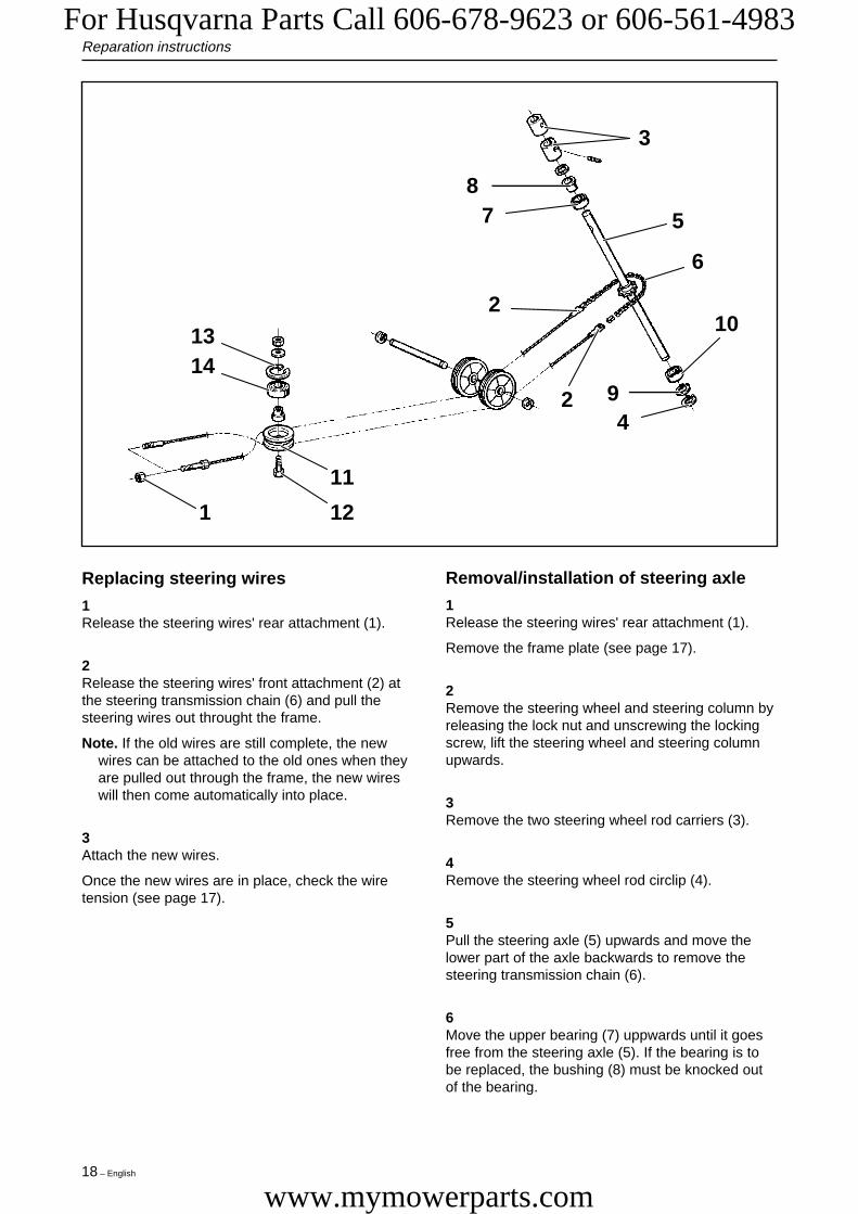
Replacing steering wires
1Release the steering wires' rear attachment (1).
2Release the steering wires' front attachment (2) atthe steering transmission chain (6) and pull thesteering wires out throught the frame.
Note. If the old wires are still complete, the newwires can be attached to the old ones when theyare pulled out through the frame, the new wireswill then come automatically into place.
3Attach the new wires.
Once the new wires are in place, check the wiretension (see page 17).
Removal/installation of steering axle
1Release the steering wires' rear attachment (1).
Remove the frame plate (see page 17).
2Remove the steering wheel and steering column byreleasing the lock nut and unscrewing the lockingscrew, lift the steering wheel and steering columnupwards.
3Remove the two steering wheel rod carriers (3).
4Remove the steering wheel rod circlip (4).
5Pull the steering axle (5) upwards and move thelower part of the axle backwards to remove thesteering transmission chain (6).
6Move the upper bearing (7) uppwards until it goesfree from the steering axle (5). If the bearing is tobe replaced, the bushing (8) must be knocked outof the bearing.
Eng-Verk Riders 97-04-28, 16.4718
For Husqvarna Parts Call 606-678-9623 or 606-561-4983
www.mymowerparts.com

English – 19
Reparation instructions
132
3
87 5
6
10
94
2
14
11
121
7Remove the lower bearing's circlip (9) and take thebearing (10) out downwards.
8Take the steering axle out (5) downwards.
9To assemble the steering axle, the reverse order isapplied. For assembly purposes, the two steeringwheel rod carriers (3), are tightened with moment(5–10 Nm).
Removal/installation of wire wheel
1Detach the steering wires' rear attachment (1) .
2Remove the screw (12) and detach the wire wheel(11).
3Remove the bearing's circlip (13) and knock out thebearing (14).
4To install the wire wheel, the reverse order isapplied.
After installation, check the wire tension (see page17).
For Rider 1030 Bioclip and Rider 1200, there is acomplete set (attachment, wire wheel, bushing,bearing) to assemble, article no. 506 50 09-01. ForRider 850 and Rider 970, the parts are orderedseparately.
Eng-Verk Riders 97-04-28, 16.4719
For Husqvarna Parts Call 606-678-9623 or 606-561-4983
www.mymowerparts.com

20 – English
Reparation instructions
21 1
11
2
Checking and adjusting brake wire
Checking and adjusting Rider 850/970
Checking and adjusting Rider 1030 Bioclip/1200
Check that the brake is correctly adjusted bymeasuring the distance between the brake leverand the front edge of the recess on the chassis.The distance should be 0–1 mm when the brake isnot applied.
Check that the brake is correctly adjusted bypositioning the ride-on mower on a gentle slopeand applying the brake.If the ride-on mower does not stand still, the brakeneeds to be adjusted.
The brake is adjusted in the following way:
1Release the lock nuts (1).
2Stretch the wire with the adjuster screw (2) until allthe play in the wire disappears.
3Tighten the lock nuts (1) and finally check that thebrake is correctly adjusted.
!
WARNING!A badly adjusted brake can leadto reduced braking capacity.
1Remove the lock nuts (1).
2Stretch the wire with the adjuster screw (2) so thatthe distance between the brake lever and the frontedge of the recess on the chassis is 1 mm.
3Tighten the lock nuts (1) after adjustment.
When the brake wire has been adjusted, check thatthe brake lever does not have too much movement.If the lever's free movement exceeds 9 mm, thisshould be adjusted by tightening the nut on thebrake lever.
Eng-Verk Riders 97-04-28, 16.4720
For Husqvarna Parts Call 606-678-9623 or 606-561-4983
www.mymowerparts.com

English – 21
34
5
2
1
Reparation instructions
3
45
12
Checking and adjusting gear controlRider 850/970
Checking and adjusting throttle controlRider 1030/1200
Check the gear control adjustment by setting thegear change lever to the ”N” position. When thelever (4) goes easily into the neutral position, thecontrol is correctly adjusted.In other cases, the control is adjusted in thefollowing way:
1Detach the lock nut (1) on the ball joint.
2Press the locking spring (2) backwards so that thespherical socket (3) can be lifted away from thepivot on the lever (4).
3Adjust the spherical socket (3) position on theconnecting rod (5) until the right adjustment isobtained.
4Lock the setting with the lock nut (1) and press thelocking spring (2) into position.
1Detach the locking nut (1) on the ball joint.
2Press the locking spring (2) backwards so that thespherical socket (3) can be lifted away from the pivoton the lever (4).
3Press the throttle pedal to the bottom and move thelever (4) forwards as far as it goes using ascrewdriver.
4Adjust the spherical socket (3) position on theconnecting rod (5) so that it just passes over thepivot on the lever.
5Lock the setting with the lock nut (1) and press thelocking spring (2) into position.
IMPORTANT INFORMATIONCheck that the locking spring goes through the hole inthe spherical socket.
Eng-Verk Riders 97-04-28, 16.4721
For Husqvarna Parts Call 606-678-9623 or 606-561-4983
www.mymowerparts.com

22 – English
Reparation instructions
A
5
6
3
1
2
4
3 21
Checking and adjusting freewheelclutch Rider 850/970
1
Replacing articulated steering bearing
1
2
2
The freewheel clutch is correctly adjusted when thetensioning wheel's outward movement is stoppedby the belt and not by the wire.
• Remove the engine according to the earlierdescription (see page 12).
• Block up the ride-on mower in front of thearticulated steering.
There should be a play (A) of 8-10 mm betweenthe wire nipple and the lever.
Adjust the freewheel clutch wire as follows:
• Pull off the rubber sleeve (1). Loosen the nuts(2) and stretch the wire with the adjuster screw(3).
• Tighten the lock nuts (2) after adjustment.
• Release the tensioning wheel spring (1).
• Release the clutch, gear and brake wire (2, 3and 4) and remove the wires' holder plates (5and 6).
3
Eng-Verk Riders 97-04-28, 16.4722
For Husqvarna Parts Call 606-678-9623 or 606-561-4983
www.mymowerparts.com

English – 23
Reparation instructions
1
2
1
2
3 5
• Loosen the steering wires (1) and remove thesteering rim.
• Remove the pulley (2). Move the lower partforwards, the upper part backwards and detachthe pulley.
Remove the inner circlip (1) from the lower bearing(see diagram). The rear section is now loose andcan be moved. Then detach the outer circlip (2) andtake the bearing out downwards.
64
Detach the articulation spring. This spring isstrongly tensioned and should be secured with toolno. 506 89 93-01 before the nut is removed.
• Take the upper bearing out upwards, if it doesnot come out easily, it should be knocked outfrom below.
• Insert the new bearings and assemble thearticulated steering in the reverse removal order.
• After re-assembly, the wire tension should bechecked (see page 17). Also check that thecontrols and wires are correctly adjusted (see pp.20–22).
WARNING!The articulation spring is stronglytensioned and can cause injury if itflies off. Wear safety glasses andgloves when removing/attachingthe spring.
!
Eng-Verk Riders 97-04-28, 16.4723
For Husqvarna Parts Call 606-678-9623 or 606-561-4983
www.mymowerparts.com

24 – English
1 2
76
4
1
2
53
Reparation instructions
Removal of swing axle 3
1
• Block-up the machine in front of the rear frame.
• Remove the transmission/gear box cover.
Remove the circlip and washer from the swingaxle's inner holder (1) and pull the swing axle outbackwards.
If the dust protection (2) is damaged, this should bereplaced by a new one.
• Detach the tensioning wheel spring (1) and theclutch wire (2).
• Disconnect the tensioning wheel arm (3) fromthe rear frame, and detach the belt from the gearbox pulley.
• Detach the gear and brake wires (4 and 5) andremove the wires' holding plates (6).
• Remove the circlip and washer from the swingaxlel (7) and pull the rear frame out backwards.
• Grease half of the axle (the half without turndown) and press it from the back into thesteering spindle (see diagram).
• Attach the washer and circlip on the swing axle'sinner holder.
• Fix the dust guard (with a thin lip behind) approx.2/3 of the way in on the axle and lubricate theaxle on both sides of the dust guard.
Installation of swing axle
1
Eng-Verk Riders 97-04-28, 16.4724
For Husqvarna Parts Call 606-678-9623 or 606-561-4983
www.mymowerparts.com

English – 25
Reparation instructions
7
6
4
12
5
345
6
7
2 4
Roll the rear frame forwards and press it in on theswing axle.
After installation of the swing axle, lubricate thelubricating area above the swing axle housing withmolybdenum disulphide grease. Also check that thewires and controls are correctly adjusted justerade(see page 20–22). Finally, attach the transmission/gear box cover.
3
Removal/installation of gear box
1
• Attach a washer and circlip onto the swing axle(1).
• Firmly secure the wires' holder plates (2), as wellas the gear and brake wires (3 and 4).
• Connect the belt onto the pulley and tightly screwthe tensioning wheel arm (5) onto the rear frame.
• Attach the clutch wire (6) and the tensioningwheel spring (7).
• Block-up the machine in front of the rear frameand dismantle the rear wheels.
• Remove the cover from over the gear box.
Eng-Verk Riders 97-04-28, 16.4725
For Husqvarna Parts Call 606-678-9623 or 606-561-4983
www.mymowerparts.com

26 – English
2
Reparation instructions
2
15
3
5
4
5
83
1
26
9
5
4
7
3
2
Removing/installation of hydrostatictransmission Rider 850 HST, Rider 970HST
1
• Release the tensioning wheel spring (1) andremove the tensioning wheel arm (2).
• Dettach the drive belt (3).
• Release the brake wire spring (4) and removethe brake wire from the brake lever (5).
• Dismantle the throttle control (6) and disconnectthe hydrostatic transmission breaker cable (7).
• Release the clamp which holds the throttle wireand the cable (8) and lay the wire and cable toone side.
• Release the disengaged clutch control spring (9).
• Block-up the machine in front of the rear frameand remove the back wheels.
• Remove the transmission cover.
• Lower the garage jack and pull out the gear box.
• Installation of the gear box is carried out in thereverse removing gear box order
• After installation, check that the clutch, brakeand gear wires are correctly adjusted (see pp.20–22).
• Release the tensioning wheel spring (1).
• Unfasten the clutch wire (2), and detach the beltfrom the gear box pulley.
• Detach the gear and brake wires (3 and 4).
• Insert a garage jack under the gear box andunscrew the gear box's five holder screws (5).
Eng-Verk Riders 97-04-28, 16.4726
For Husqvarna Parts Call 606-678-9623 or 606-561-4983
www.mymowerparts.com
English – 27
Reparation instructions
1
2
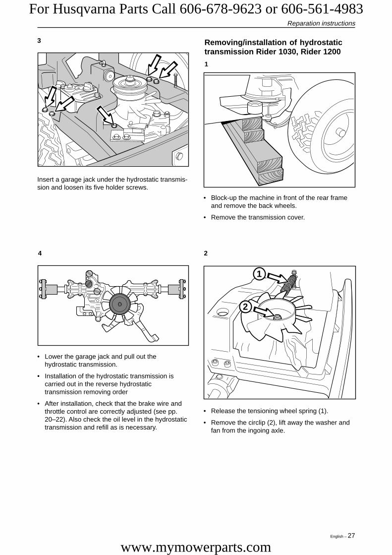
3 Removing/installation of hydrostatictransmission Rider 1030, Rider 1200
1
Insert a garage jack under the hydrostatic transmis-sion and loosen its five holder screws.
4 2
• Lower the garage jack and pull out thehydrostatic transmission.
• Installation of the hydrostatic transmission iscarried out in the reverse hydrostatictransmission removing order
• After installation, check that the brake wire andthrottle control are correctly adjusted (see pp.20–22). Also check the oil level in the hydrostatictransmission and refill as is necessary.
• Release the tensioning wheel spring (1).
• Remove the circlip (2), lift away the washer andfan from the ingoing axle.
• Block-up the machine in front of the rear frameand remove the back wheels.
• Remove the transmission cover.
Eng-Verk Riders 97-04-28, 16.4727
For Husqvarna Parts Call 606-678-9623 or 606-561-4983
www.mymowerparts.com

28 – English
Reparation instructions
12
3
4
21
3 5
4 6
Disconnect the contact (1) and take off the hose(2). Ensure that the oil does not run out, e.g. tie upthe hose higher than the oil level in the container.
• Lower the garage jack and pull out thehydrostatic transmission.
• Installation of the hydrostatic transmission iscarried out in the reverse hydrostatictransmission removing order
• After installation, check that the brake wire andthrottle control are correctly adjusted (see pp.20–22). Also check the oil level in the containerand refill as is necessary.
• Detach the drive belt (1) and release the brakewire spring (2).
• Disconnect the brake wire (3) and dismantle thethrottle control (4).
• Remove the spring (5) and the disengagedclutch control (6).
Insert a garage jack under the hydrostatictransmission and loosen its five holder screws.
Eng-Verk Riders 97-04-28, 16.4728
For Husqvarna Parts Call 606-678-9623 or 606-561-4983
www.mymowerparts.com

English – 29
1
2 2
Reparation instructions
Replacing hydrostatic transmissionaxle sealing collars
1
2
• Wrap insulation tape around the ingoing axle toprotect the new sealing collar from damage tosplines and grooves.Start by wrapping from the bottom and continueupwards over the axle until the entire axle iswrapped in tape.
• Lubricate the axle and the inside of the newsealing collar with grease so that the collar canslide easily.
Sealing collar replacement - ingoing axle1
Take the hydrostatic transmission out of the ride-on mower, as indicated in previous description(see page 26).Remove the pulley (1) from the ingoing axle bypulling it upwards. Then dismantle the circlip underthe pulley.
2Dismantle the circlips which hold the wheel hubs(2) at the axles and remove the hubs by pullingthem outwards. Do not lose the key which sitsbetween the hub and the axle.
• Clean the ingoing axle and the area around thesealing collar of all dirt and rust.
• Insert a screwdriver between the sealing collarand the axle and bend the sealing collar out ofthe axle housing with a twisting motion.
IMPORTANT INFORMATION
The area around the sealing collar mustbe absolutely clean! If the hydrostatic oilis contaminated with dirt, this can lead toa shorter hydrostatic transmissionoperational life.
• Place the sealing collar on the axle with thesmooth side upwards, and carefully press itdownwards.
• Use the thick end of a 1/4" extender to carefullyknock down the sealing collar until the upside ofthe collar is level with the axle housing's upperedge.Move the extender in a circle around the sealingcollar so that it is evenly pressed down, all theway around.
• Remove the insulation tape from the axle andassemble the lower circlip and the pulley with thehexagonal hub facing upwards.
• Fasten the fan and the washer and assemble theupper circlip.
• Install the hydrostatic transmission in the ride-onmower as indicated in the previous description(see page 26).
3
Eng-Verk Riders 97-04-28, 16.4829
For Husqvarna Parts Call 606-678-9623 or 606-561-4983
www.mymowerparts.com

30 – English
Reparation instructions
Sealing collar replacement - outgoing axles1
IMPORTANT INFORMATION
Dirt must not be allowed to get into thetransmission as this can shorten itsoperational life.
2
• Wrap insulation tape around the outgoing axlefrom the start of the key-way and outwards untileven the circlip's groove is covered with tape.This is done to protect the new sealing collarfrom damage.
• Lubricate the axle and the inside of the newsealing collar with grease so that the collar canslide easily.
• Place the sealing collar on the axle, with themetal spring inwards, and press it in carefully.
• Use the narrow end of a 1/4" extender tocarefully knock in the sealing collar until itreaches the bottom of the axle housing. Onlyknock on the steel cover.Move the extender in a circle around the sealingcollar so that it is pressed in evenly all the wayaround and tight against the axle.
• Remove the insulation tape from the axle andrepeat, as is necessary, the entire procedure forthe second axle.
• Install the hydrostatic transmission in the ride-onmower as indicated in the previous description(see page 26).
IMPORTANT INFORMATION
Before the sealing collar is completelyinstalled, check that the sealing collar'smetal spring reinforcement sits on theside of the sealing collar which leadsinwards towards the transmission.
• Fill the transmission's oil container with SAE10W30 oil until the oil level reaches the "MAX"-marking.
• Operate the ride-on mower and then check thatthere is no oil leaking from the new axle sealingcollars.
• Clean the outgoing axle and the area around thesealing collar of all dirt and rust.
• Insert a screwdriver between the sealing collarand the axle and bend the sealing collar out ofthe axle housing with a twisting motion.
3
Eng-Verk Riders 97-04-28, 16.4830
For Husqvarna Parts Call 606-678-9623 or 606-561-4983
www.mymowerparts.com

English – 31
Reparation instructions
1
2
2
21
Hydrostatic transmission brake
Removal of brake1
• Place blocks in front of and behind the wheels sothat the ride-on mower can not roll. Then,release the parking brake.
• Remove the split pin and the washer from thebrake's connecting rod (1).
• Remove the three bolts and washers (2) from thetransmission and detach the brake lining packet.
2 2
Remove the brake drum by removing the circlip andpulling the drum outwards.
Install the brake spring with holder on the gold-coloured brake arm by passing the recesses intothe holder with metal tabs on the brake arm. Then,turn the holder in towards the transmission.
Installation of brake1
• Put the brake drum on the axle and attach thecirclip.
• Assemble the brake lining packet on thetransmission and tighten the three bolts andwashers by hand.
• Press the brake lever (1) backwards so that thebrake lining locks the drum, and draw the threebolts with moment to 27 Nm (20 ft, lbs.), whilstthe drum is locked.
IMPORTANT INFORMATION
It is seldom necessary to remove thebrake drum. If, however, it needs to beremoved, a puller and/or penetrating oil isneeded to get it off.
IMPORTANT INFORMATION
Firmly fix the spring holder so that theholder's metal tabs (shown by the arrows)point away from the transmission.
Eng-Verk Riders 97-04-28, 16.4831
For Husqvarna Parts Call 606-678-9623 or 606-561-4983
www.mymowerparts.com

32 – English
Reparation instructions
3 2
• Firmly attach the brake's connecting rod in thehole on the brake lever and assemble thewasher and spring clip.
• Remove the blocks in front of and behind thewheels and continue with ”Adjusting brake”.
Adjustment of brake1
Apply the parking brake and check that thetransmission's brake arm is pulled as far forwardsas possible (see diagram). Adjust this with thebrake wire tensioning screw.
When the parking brake is fully applied, the gapbetween the spring and the spring holderattachment (see diagram) should be 4–8 mm.
3IMPORTANT INFORMATION
Firmly attach the connecting rod so that thewasher and the spring clip are on theoutside of the brake lever (see diagram).
Adjust the gap by:
• Releasing the parking brake.
• Loosening the connecting rod by removing thespring clip and the washer.
• Turning the connecting rod in or out of the spring(see diagram) to adjust the gap.
• Firmly attach the brake's connecting rod in thehole on the brake lever and assemble thewasher and spring clip. Make sure that thewasher and spring clip are on the outside of thebrake lever.
• Apply the parking brake and check the gap onceagain.
• Repeat the adjustment procedure until thecorrect gap is obtained.
Eng-Verk Riders 97-04-28, 16.4832
For Husqvarna Parts Call 606-678-9623 or 606-561-4983
www.mymowerparts.com

English – 33
Reparation instructions
1
2
Bleeding the hydrostatic transmissionoil system
1
4
2
• Check the hydrostatic transmission oil level.
• Start the engine and set the throttle control to lowidle.
For immediate bleeding of the oil system, fill new oildirectly into the transmission (1) and, at the sametime, pull the pump round by hand with the brakedrum (2).
• Repeat opening and closing the disengagedclutch control whilst the front respective rearpedals are alternately pressed down.
• When the ride-on mower starts to move, thegovernor control lever should be increased tohigh idle.
3
• Repeat quick starts and emergency stops untilthe transmission responds as it should.
• Finally, check the hydrostatic transmission oillevel and fill as is required.
• The neutral position is adjusted by turning thehexagonal axle on the transmission (seediagram).
• Start the engine and set the throttle control to fullthrottle.
• Unscrew the hexagonal axle lock nut and turnthe axle clockwise until the drive shafts start torotate backwards.
• Make a mark on the top of the axle.
Adjustment of transmission neutralposition
1Bleed the hydrostatic transmission oil system.
2Lift the back of the ride-on mower up so that thewheels are off the ground and place blocks under themachine.
3
Eng-Verk Riders 97-04-28, 16.4833
For Husqvarna Parts Call 606-678-9623 or 606-561-4983
www.mymowerparts.com

34 – English
RS 1/3 FS
1
2
N8° FS
1
2
N
Reparation instructions
4 5
1 = Axle2 = Lock nut
1 = Axle2 = Lock nut
If the drive shafts do not rotate backwards despitethe hexagonal axle having rotated a full turn, theneutral position is to be adjusted in the followingway:
• Slowly turn the axle anti-clockwise until the driveshafts start to rotate forwards.
• Slowly turn the axle clockwise until the driveshafts stop rotating forwards and make a markon the transmission housing (FS) and the axle.
• Turn the axle clockwise 8° from the mark on thetransmission housing.
• Hold the axle (M8) firmly and tighten the lock nut(M17).
Ineffective brake powerAs the brake is only used as a parking brake, wearis negligeable. If the brake power is neverthelessineffective, this can be adjusted:
• Release the three bolts (N12) which hold thebrake lining packet.
• Press on the brake lever so that the brake liningcentres itself around the brake drum and tightenthe three bolts with moment (27 Nm).
• Slowly turn the axle anti-clockwise until the driveshafts stop rotating backwards and make a markon the transmission housing (RS).
• Slowly turn the axle anti-clockwise until the driveshafts start to rotate forwards.
• Slowly turn the axle clockwise until the driveshafts stop rotating forwards and make a markon the transmission housing (FS).
• Turn the axle clockwise 1/3 of the distancebetween the marked stop points.
• Hold the axle (M8) firmly and tighten the lock nut(M17).
• Check that the drive shafts do not rotate in theneutral position by slowly transferring thesteering arm to the neutral position from theforwards and reverse positions.
Transmission maintenance
Oil changeMost garden owners do not have tools for orexperience of changing transmission oil. Thetransmission probably has a longer operational lifethan other ride-on mower components, this makestransmission oil changes less important for mostcustomers. However, the transmission's operationallife is increased if oil changes are made.
If the ride-on mower is used professionally, it isrecommended to change the oil firstly after 50hours use and every 200 hours use thereafter.
The oil filter only needs to be changed if the trans-mission is opened for repairs to be made.
The transmission holds 3.3 litres SAE10W/30engine oil, class CD–SF.
Eng-Verk Riders 97-04-28, 16.4834
For Husqvarna Parts Call 606-678-9623 or 606-561-4983
www.mymowerparts.com

English – 35
1
2
3
Reparation instructions
R I D E R 8 5 0
R I D E R 8 5 0
R I D E R 8 5 0
2
Checking and adjusting mower deckground pressure Rider 970/1030Bioclip/1200
1
Place a set of bathroom scales under the mowerdeck's frame (front edge) so that the deck rests onthe scales.
Adjust the mowing deck's ground pressure with theadjuster nuts placed behind the front wheels onboth sides of the ride-on mower. The groundpressure should be between 12 and 15 kg.
Checking and adjusting mower deckparallelism
1
2
Adjusting Rider 1030 Bioclip/1200
Place the ride-on mower on an even surface andmeasure the distance between the ground and theedge of the deck, at the front and rear of the cover.If the values correspond, the deck is parallel.
• Remove the front cover, as well as the right andleft fenders.
• Unscrew the lock nuts (1) and (2). Note that theends of the strut are right respective left-handed.
• Place a key over the chamfering (3) in the middleof the strut and screw the strut forwards orbackwards to raise or lower the front edge of thecover.
• Tighten the lock nuts after adjustment.
• After adjustment, the deck's parallelism is to bechecked. Thereafter, re-attach the front cover aswell as the right and left fenders.
Eng-Verk Riders 97-04-28, 16.4835
For Husqvarna Parts Call 606-678-9623 or 606-561-4983
www.mymowerparts.com
36 – English
Reparation instructions
1 23
2
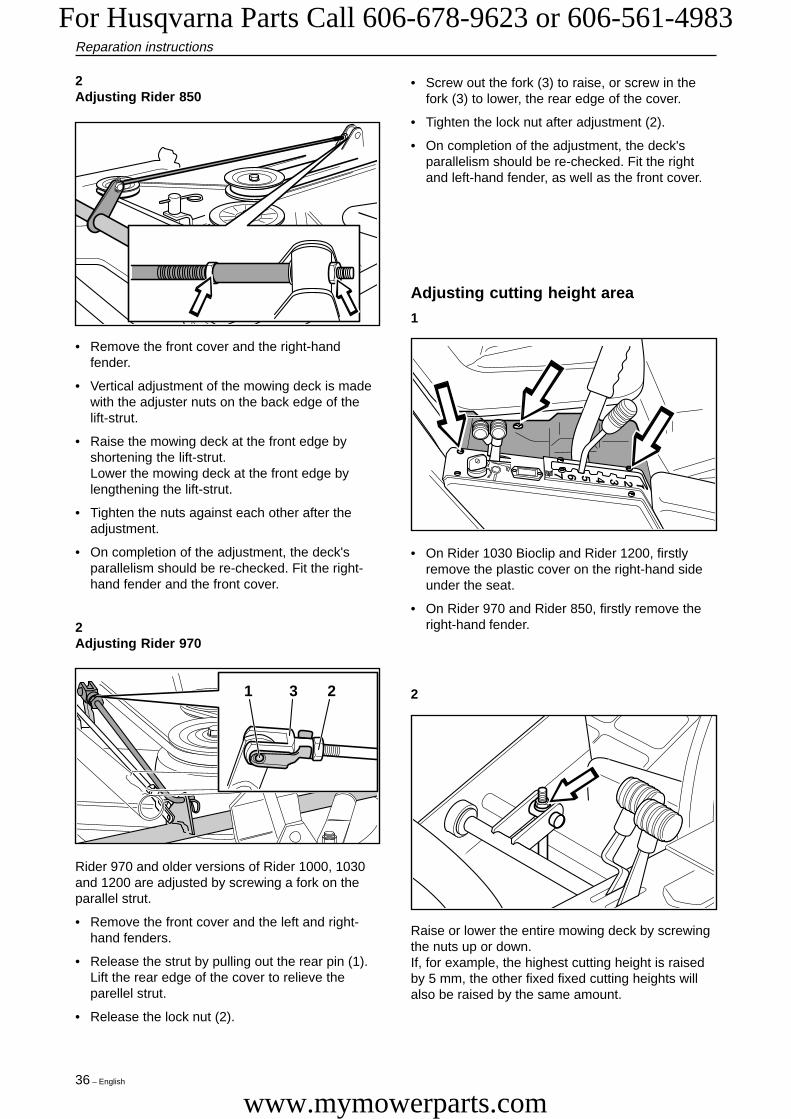
2Adjusting Rider 850
• Remove the front cover and the right-handfender.
• Vertical adjustment of the mowing deck is madewith the adjuster nuts on the back edge of thelift-strut.
• Raise the mowing deck at the front edge byshortening the lift-strut.Lower the mowing deck at the front edge bylengthening the lift-strut.
• Tighten the nuts against each other after theadjustment.
• On completion of the adjustment, the deck'sparallelism should be re-checked. Fit the right-hand fender and the front cover.
2Adjusting Rider 970
Rider 970 and older versions of Rider 1000, 1030and 1200 are adjusted by screwing a fork on theparallel strut.
• Remove the front cover and the left and right-hand fenders.
• Release the strut by pulling out the rear pin (1).Lift the rear edge of the cover to relieve theparellel strut.
• Release the lock nut (2).
• Screw out the fork (3) to raise, or screw in thefork (3) to lower, the rear edge of the cover.
• Tighten the lock nut after adjustment (2).
• On completion of the adjustment, the deck'sparallelism should be re-checked. Fit the rightand left-hand fender, as well as the front cover.
Adjusting cutting height area
1
• On Rider 1030 Bioclip and Rider 1200, firstlyremove the plastic cover on the right-hand sideunder the seat.
• On Rider 970 and Rider 850, firstly remove theright-hand fender.
Raise or lower the entire mowing deck by screwingthe nuts up or down.If, for example, the highest cutting height is raisedby 5 mm, the other fixed fixed cutting heights willalso be raised by the same amount.
2
Eng-Verk Riders 97-04-28, 16.4836
For Husqvarna Parts Call 606-678-9623 or 606-561-4983
www.mymowerparts.com

English – 37
Reparation instructions
2
3
1
45
Removal of mowing deck Rider 1030and Rider 1200
Removal of mowing deck Rider 970
1Remove the front cover. Set the cutting height tothe lowest position.
2Relieve the connecting rod (1). A breaking bar maybe used, when the hair-needle spring is removed,to carefully bend the connecting rod out of itsholder.
3Release the tensioning wheel (2) by disconnectingthe spring (3).
4Bend the locking plate (5) forwards and press downthe deck's front edge so that it is released from thedeck frame (4).
5Press the deck backwards and twist off the drivebelt. Then pull the deck forwards so that the backend is released from the deck frame.
6Installing the mowing deck takes place in thereverse order to removal.
1Remove the front cover.
2Set the cutting height to the highest position. Pushthe stop (1) in against the crossbar and then setthe cutting height to the lowest position. Themowing deck is now locked vertically.
3Relieve the tensioning roller (2) by disconnectingthe spring (3).
4Bend the locking plate (5) forwards and press downthe deck's front edge so that it is released from thedeck frame (4).
5Press the deck backwards and twist off the drivebelt.
6Remove the hair-needle spring and release thecrossbar (6) from the height adjustment.
7The deck can now be pulled forward until itreleases from the rear suspension.
8Installing the mowing deck takes place in thereverse order.
WARNING!When working on the mowing deck, wear protective glasses andgloves.
2 3
5
4
6
1
!
Eng-Verk Riders 97-04-28, 16.4837
For Husqvarna Parts Call 606-678-9623 or 606-561-4983
www.mymowerparts.com

38 – English
Reparation instructions
1
2
Removal of mowing deck Rider 850
1
• Remove the front cover as well as the left andright-handed fender.
• Raise the mowing deck by pulling the lift leverbackwards to the transport position.
• Dismantle the drive belt (1).
• Lower the mowing deck by pressing in the liftlever lock button and moving the lever to thecutting position.
• Set the lowest cutting height with the cuttingheight lever.
• Take the hair-needle spring (2) out of the chainretainer.
22
• Remove the lock pins (one on each side) on therear edge of the unit.
• Installation of the mowing deck takes place in thereverse order.
WARNING!
When the lock pins are removed, thedeck will drop to the ground. Makesure to keep your hands or fingersaway from under the deck duringthe removal.
Replacing mowing deck belts
Belt replacement on bioclip-deck
A bioclip-deck is driven by two synchronoustransmission belts which synchronise the rotationof the blades. The belts are situated under a coveron the mowing deck. Replace the belts in thefollowing way:1
Release the parellel strut's front pin and bend thestrut backwards.
Unscrew the two screws which hold the safetyguard and lift off the guard.
!
Eng-Verk Riders 97-04-28, 16.4838
For Husqvarna Parts Call 606-678-9623 or 606-561-4983
www.mymowerparts.com

English – 39
Reparation instructions
90° 90°
10 N
7 mm
3 5
• Loosen the eccentric plate nut and twist it off.
• Loosen the four nuts (see diagram), which holdthe outer blade bearing, so much so that thebearing can be moved.
• Press the blade bearing inwards towards themiddle bearing and twist off the upper belt.
• Repeat the procedure with the lower belt.
• Tension the belts by twisting in the eccentrictensioning device on the upper side of themowing cover. Tighten the nut.
• Tighten all the nuts holding the blabe bearings.
• When the belt moves 7 mm inwards at a force of10N, the belt tension is correct.
• Fit the safety guard over the belts and attach theparellel strut.
Belt replacement on mowing deck with side orrear discharge
On mowing decks with side or rear discharge theblades are driven by a single V-belt. Replace the V-belt in the following way:
• Release the spring which tensions the V-belt andtwist off the belt.
• Installing the new belt is carried out in thereverse order.
Fit the new belts in the following way:
• First, twist on the lower belt and then the upperone.
• Check that the blades are positioned inaccordance with the diagram with 90° betweenthem, otherwise the belts should be adjusted.When the blade bearing is loose, the belt can beslipped over to the next gear.
• Tighten the nuts so that the bearings lie close tothe cutting cover, but so that they can be displa-ced.
IMPORTANT INFORMATION
On a bioclip-deck the relative positioningof the blades should always be as shownin the diagram with an angle of 90°between the blades. Otherwise, theblades can go against each other anddamage the deck.
WARNING!When working with the blades,use protective gloves.
!
4
Eng-Verk Riders 97-04-28, 16.4839
For Husqvarna Parts Call 606-678-9623 or 606-561-4983
www.mymowerparts.com

40 – English
21
Reparation instructions
Removal of blades with bearings
1
WARNING!When working with the mowingdeck, use protective glasses andgloves.
2
Unscrew the screw which holds the blade andremove the screw, washer and blade.
3
Unscrew the four screws which hold the bladebearing and remove the entire bearing packet fromthe mowing deck.
4
Remove the hub using a puller. Do not lose the keywhich is found between the pulley and the axle.
5
Remove the sheet metal safety washer.
• Release the spring which tensions the V-belt andtwist off the belt.
• Unscrew the screw which holds the pulley (2)and detach the pulley, a puller may be neededfor this. Do not lose the key which is foundbetween the pulley and the axle.
!
Eng-Verk Riders 97-04-28, 16.4840
For Husqvarna Parts Call 606-678-9623 or 606-561-4983
www.mymowerparts.com

English – 41
Reparation instructions
6
• Press out the axle with a puller.
• Knock out the bearings and remove the spacer.
7
The entire packet can be bought as a complete setwith axle housing, axle, spacer and bearing. TheRider 1200 set does not include an axle.
Model Outer bearing Middle bearing
Rider 850 506 53 34-01 506 53 34-02Rider 970 506 75 11-01 506 75 11-04Rider 970 Bioclip 506 75 11-05 506 75 11-04Rider 1030 Bioclip 506 75 11-05 506 75 11-04Rider 1200 506 75 11-01 506 75 11-03
Installation is carried out in the reverse removingorder. Ensure that the axle is fixed in the samedirection as it was removed, if not the keys will notfit into the key-way.
IMPORTANT INFORMATION
When screwing on the blade axle screws,the transmission side should always bescrewed first and then the blade screws.
Grinding and balancing of blades
1
• Remove the blades according to the decription inthe previous section.
• Clamp the blade in a screw vice and file it so thatit becomes sharp.
2
Balance the blade as follows:
• Fix, for example, a mandrel horizontally in ascrew vice according to the diagram.
• Push the blade onto the mandrel via the hole inthe centre of the blade and check that the bladebalances evenly. The diagram shows a bladewhich needs to be adjusted, it must be groundfurther to obtain the correct balance (at thearrow).
• Installation is carried out in the reverse removingorder.
WARNING!When working with the blades, useprotective gloves.
!
Eng-Verk Riders 97-04-28, 16.4941
For Husqvarna Parts Call 606-678-9623 or 606-561-4983
www.mymowerparts.com

42 – English
Electrical systemCircuit diagram Rider 850
1. Microswitch, seat2. Ignition lock3. Microswitch, lifting lever4. Microswitch, gear position5. Fuse 15A6. Starter relay7. Engine/charging8. Engine/stop
Key to colour abbreviations in the electrical systemSV = BlackRD = RedBR = BrownBL = BlueVT = WhiteGL = YellowGR = Green
8
7 6
1
53
2
4
Eng-Verk Riders 97-04-28, 16.4942
For Husqvarna Parts Call 606-678-9623 or 606-561-4983
www.mymowerparts.com
English – 43
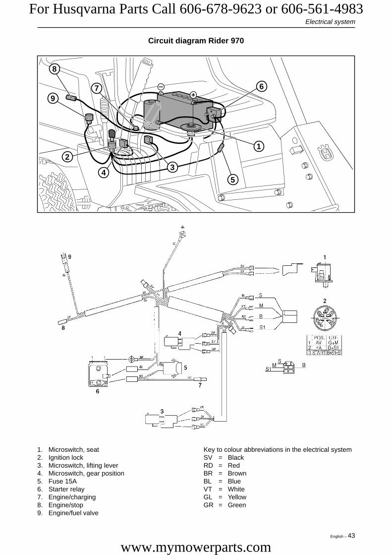
Circuit diagram Rider 970
Electrical system
1. Microswitch, seat2. Ignition lock3. Microswitch, lifting lever4. Microswitch, gear position5. Fuse 15A6. Starter relay7. Engine/charging8. Engine/stop9. Engine/fuel valve
Key to colour abbreviations in the electrical systemSV = BlackRD = RedBR = BrownBL = BlueVT = WhiteGL = YellowGR = Green
9
8
7 6
1
5
32
4
Eng-Verk Riders 97-04-28, 16.4943
For Husqvarna Parts Call 606-678-9623 or 606-561-4983
www.mymowerparts.com

44 – English
Electrical system
Circuit diagram Rider 850/970 HST
Key to colour abbreviations in the electrical systemSV = BlackRD = RedBR = BrownBL = BlueVT = WhiteGL = Yellow
1. Microswitch, seat2. Ignition lock3. Microswitch, lifting lever4. Microswitch, hydrostatic transmission5. Fuse 15A6. Starter relay7. Engine/charging8. Engine/stop9. Engine/fuel valve
8
7 6
1
5
4
2
3
9
Eng-Verk Riders 97-04-28, 16.4944
For Husqvarna Parts Call 606-678-9623 or 606-561-4983
www.mymowerparts.com

English – 45
Circuit diagram Rider 1030 Bioclip/1200
Electrical system
3
5
4
6
2
1
7
1. Brake switch, hydrostatic transmission2. Microswitch, mowing deck3. Microswitch, seat4. Ignition lock5. Timing unit6. Starter relay7. Engine
Key to colour abbreviations in the electrical systemRD = RedBL = BlueVT = WhiteSV = BlackGL = TellowBR = Brown
Eng-Verk Riders 97-04-28, 16.4945
For Husqvarna Parts Call 606-678-9623 or 606-561-4983
www.mymowerparts.com


HusqvarnaPrinted in U.S.A.
For Husqvarna Parts Call 606-678-9623 or 606-561-4983
www.mymowerparts.com


