For Fuego and Robin Kilns · For Fuego and Robin Kilns 1. TABLE OF CONTENTS FOR L&L FUEGO AND ROBIN...
57
INSTRUCTION & REFERENCE MANUAL L&L Kilns are imported into the United Kingdom by Potclays LTD 65 years of excellence 201 by L&L Kiln Mfg., Inc. For Fuego and Robin Kilns 1
-
Upload
vuongduong -
Category
Documents
-
view
230 -
download
1
Transcript of For Fuego and Robin Kilns · For Fuego and Robin Kilns 1. TABLE OF CONTENTS FOR L&L FUEGO AND ROBIN...
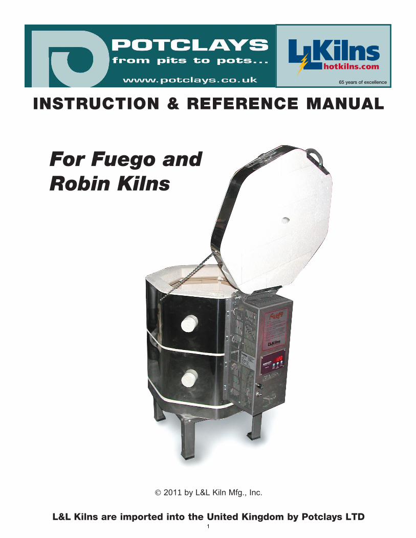
INSTRUCTION & REFERENCE MANUAL
L&L Kilns are imported into the United Kingdom by Potclays LTD
65 years of excellence
2011 by L&L Kiln Mfg., Inc.
For Fuego and Robin Kilns
1
TABLE OF CONTENTS FOR L&L FUEGO AND ROBIN KILNS(POTCLAYS VERSION)
fuego-robin-potclays-toc.pdf REV:10/1/2011 Page1 2010 L&L Kiln Mfg, Inc. 505 Sharptown Rd, Swedesboro NJ 08085 P:856.294.0077 F:856.294.0070 [email protected] hotkilns.com
TABLE OF CONTENTS
INSTRUCTIONS FOR L&L FUEGO, ROBIN,& LIBERTY-BELLE KILNS . . . . . . . . . . . . . . . 3
FIRST FIRING INSTRUCTIONS . . . . . . . . . . 10
ONE-TOUCH INSTRUCTIONS . . . . . . . . . . . 12
ASSEMBLY INSTRUCTIONS FOR L&L FUEGO, ROBIN, & LIBERTY-BELLE KILNS . . . . . . . . 24
WIRING DIAGRAM . . . . . . . . . . . . . . . . . . . . . 32
PARTS FOR ALL KILNS(ONLINE DATABASE) . . . . . . . . . . . . . . . . . . . 33
TROUBLESHOOTING AND REPAIRINSTRUCTIONS FOR L&L FUEGO, ROBIN,& LIBERTY-BELLE KILNS . . . . . . . . . . . . . . . 34
KILN PANEL INFORMATION . . . . . . . . . . . . 56
POTCLAYS CONTACT INFORMATION . . . . 57
2
INSTRUCTIONS FOR L&L FUEGO, ROBIN, & LIBERTY-BELLE KILNS(ALL VERSIONS)
fuego-robin-liberty-instructions.pdf REV:10/1/2011 Page1 2011 L&L Kiln Mfg, Inc. 505 Sharptown Rd, Swedesboro NJ 08085 P:856.294.0077 F:856.294.0070 [email protected] hotkilns.com
IMPORTANT CAUTIONS
INSTALLATION CAUTIONS
AMBIENT TEMPERATURESOperate in an environment between 0°C and 38°C (32 - 100°F).
CLEARANCESInstall kiln a minimum of 30 cm (12”) away from any wall, although a minimum of 45 cm (18”) is preferable. Maintain a minimum of 90 cm (36”) between two adjacent kilns especially if they are going to be used at the same time.
YOU MUST USE THE SUPPLIED KILN STANDNever set a kiln on a floor without significant air space circulating under the kiln. This is part of the insulation system of the kiln. Level the stand while installing.
WALL AND FLOOR MATERIALSWalls and floors must be non-combustible. Recommended floor surfaces are cement, ceramic tile, stone, slate, breeze blocks or brick. Do not install on a wood floor or on carpet. Vinyl flooring may also be combustible. Protect linoleum flooring from discoloration with a non-combustible covering. Remember that the kiln radiates heat over a long period of time and that this could start a fire under certain conditions. The continued heat of the kiln can dry out combustible surfaces over time and lower the temperature at which they could start burning. Temperatures at combustible ceilings and floors should be kept below 70°C (160°F). Check temperatures around the kiln while firing.
REQUIRED VENTILATION FOR THE KILNIt is important to vent the room that the kiln is operating in. Kilns generate harmful fumes and heat when firing ceramics. Fumes can include carbon monoxide, formaldehyde, sulphur dioxide, heavy metal vapours, and fluorides (all of which can be very toxic). Install kiln in a well-ventilated area. Never operate in an enclosed space (such as a closet) without proper ventilation. The heat in an enclosed room could present a significant fire hazard. Severe corrosion can be caused by kiln fumes, salt air or other environmental conditions. Ventilation
must be to the outside (and not under a window).
USE COPPER WIRE FOR HOOK UPDo not use aluminum wire.
PROTECT POWER LEAD FROM KILN CASERoute Power Lead away from kiln in such a way that it cannot touch the hot case of the kiln. Secure wires so they cannot move.
KEEP KILN DRY & IN PROTECTED SPACEThe kiln must be kept dry. Water in contact with a kiln can cause an electrocution hazard.
FIRE EXTINGUISHERKeep an adequate fire extinguisher (rated for electrical fires) near the kiln and check it yearly or according to local codes.
GENERAL ENVIRONMENT CAUTIONS
SURFACE IS HOT AND CAN CAUSE BURNSKiln surface can be extremely hot (up to 260°C/ 500°F) and can cause severe burns if touched.
KEEP CHILDREN & ANIMALS AWAY FROM KILNProtect children, animals, and unqualified adults from the kiln.
KEEP FLAMMABLES AWAY FROM KILNAvoid flammable or loose clothing around kiln.
PRE-FIRING CAUTIONS
PROPER USE OF KILN WASHMake sure the floor of the kiln and the tops of the shelves are coated with kiln wash. This will protect these surfaces from melting glaze and ceramics. Do not coat the undersides or sides of the shelves. Do not apply kiln wash to the brick sides or element holders.
DO NOT USE SILICA SAND IN KILNSilica can damage the kiln elements.
3
INSTRUCTIONS FOR L&L FUEGO, ROBIN, & LIBERTY-BELLE KILNS(ALL VERSIONS)
fuego-robin-liberty-instructions.pdf REV:10/1/2011 Page2 2011 L&L Kiln Mfg, Inc. 505 Sharptown Rd, Swedesboro NJ 08085 P:856.294.0077 F:856.294.0070 [email protected] hotkilns.com
NEVER FIRE MOIST GREENWAREWe recommend using Preheat in your bisque programme to help dry out any moisture that you cannot see.
LOADING & UNLOADING CAUTIONS
UNPLUG KILN WHEN NOT IN USE
KEEP LID CLOSED WHEN KILN IS NOT IS IN USEDo not store anything on the closed lid or in the kiln.
DO NOT OPEN THE LID WHEN KILN IS ABOVE 120°C (250°F)
FIRING CAUTIONS
DON’T FIRE KILN ABOVE CONE 10 (1290°C, 2350°F)Note that the Robin Kiln is rated to Cone 02 (1100°C, 2012°F).
ATTEND THE FIRINGNo automatic safety device is foolproof! Be especially careful about attending the kiln while it is supposed to shut off. You can plan your firing using the Delay feature. If you can not be at the kiln all the time be sure to attend the end of the firing.
USE PROGRAMME REVIEWReview the current programme prior to starting the kiln to ensure the correct profile is programmed. This is done by pressing the Review Prog button.
USE THE PROPER THERMOCOUPLENever use a different type of thermocouple with your controller unless it has been set up from the factory. Use of a type S thermocouple will over fire your kiln. The standard thermocouples that come with the Fuego, Robin and Liberty-Belle kilns are type K. They cannot be switched to a Type S.
USE WITH THE THERMOCOUPLE PROTECTION TUBENote that the control has been programmed with a 10°C thermocouple offset to compensate for the effect of the ceramic thermocouple protection tube. If for some reason you were to use the kiln without that
protection tube the control would fire 10°C colder.
USE CAUTION WHEN VIEWING INTO THE KILNUse dark glasses (shade number 1.7 to 3.0) to view inside the kiln through the peepholes when firing. These will protect you from the radiant infrared radiation and will also protect your eyes in case the ceramic ware explodes. Do not use regular sunglasses for this.
USE CAUTION WHEN OPENING THE KILN1) Use heat resistant gloves when opening peephole plugs.
2) Use heat resistant gloves when opening a hot lid.
3) Do not open the lid when kiln is above 120°C (250°F).
POST FIRING CAUTIONS
CHECK FOR GLAZE AND CERAMIC CHIPSRemove any glaze that has splattered on the firebrick or shelves. (Use safety glasses when doing this because glaze can be sharp like broken glass). Vacuum the kiln after each firing.
GENERAL MAINTENANCE CAUTIONS
ELECTRICAL SAFETYUnplug kiln when servicing it. The elements carry high voltage when switched on and could electrocute you. Troubleshooting tests performed under power should ONLY be done by a licensed electrician.
THE WRONG PARTS CAN BE HAZARDOUSOff-brand elements, if not designed properly, can present a hazard to the kiln (by drawing too much amperage). The wrong type of fuse, relay, switch or other component can cause a fire or other hazardous condition. An improperly rated lead can cause a fire. Do not substitute or replace any parts with unauthorized products.
KILN MODIFICATIONSAll customer modification is made solely at the risk of the customer. Modifications will void the warranty. L&L takes no responsibility for hazardous conditions created
4
INSTRUCTIONS FOR L&L FUEGO, ROBIN, & LIBERTY-BELLE KILNS(ALL VERSIONS)
fuego-robin-liberty-instructions.pdf REV:10/1/2011 Page3 2011 L&L Kiln Mfg, Inc. 505 Sharptown Rd, Swedesboro NJ 08085 P:856.294.0077 F:856.294.0070 [email protected] hotkilns.com
by unauthorized modifications. Any authorization for an engineering change must be in writing from the factory.
KILN MAINTENANCESee the section at the end of this booklet on periodic maintenance you need to perform on your kiln.
OPERATION
HOW YOUR FUEGO, ROBIN OR LIBERY-BELLE KILN WORKSThe automatic program control measures the temperature inside the kiln using the thermocouple probe. The control automatically adjusts power to evenly heat up the kiln according to one of the four programs you are firing. You do not typically have to adjust anything once you start firing. However, if you are manually venting the kiln by opening the top vent hole you will have to manually close this at the appropriate point in the program (typically about 500°C / 932°F).
DIFFERENCES BETWEEN FUEGO, ROBIN & LIBERY-BELLE KILNAll these kilns use the same control system. The Fuego and Robin use the same elements and power supply. The Fuego is capable of reaching cone 10 temperatures (approximately 1290°C / 2350°F). The Robin is capable of reaching cone 02 temperatures (approximately 1100°F / 2012°F) because it is heating a larger chamber with the same power. The Liberty-Belle uses a different power supply with three separate contactors and is set up for 415 3-phase voltage.
FIRST FIRINGSee the information in this manual
CONTROL OPERATIONSee the One-Touch Instructions in this manual.
THE KILN DESIGN
NOTABLE FEATURES
SECTIONAL CONSTRUCTIONThe Fuego, Robin and Liberty-Belle LB23S kilns are made up of two separate sections that sit on top of a separate kiln bottom. They are attached together by the control panel and hinge.
CONTROL SYSTEMThe automatic programme control uses a thermocouples to sense temperature. The control then automatically adjusts power output (turns the contactor on and off) to heat up the kiln. The programme control varies the target set point for the temperature according to various ramps and soak periods that are programmed in the control. Basic operating instructions are part of this manual.
THERMOCOUPLEThe standard thermocouple is a heavy-duty 8-gauge Type K thermocouple protected with an industrial grade mullite thermocouple protection tube.
REMOVABLE CONTROL BOXThe control panel can be easily removed and sent to your distributor for repairs if ever necessary.
HEATING ELEMENTS IN CERAMIC HOLDERSThe heating elements are designed to have a low watt density and good stretch ratio. These are supported in hard ceramic element holders (a unique L&L feature). This will promote long element and firebrick life.
STURDY ALUMINIZED STEEL STANDAluminized steel resists corrosion at the high temperatures. The stand has a full plate of aluminized steel under the bottom brick. This allows the bottom brick to move freely while expanding and contracting - which helps prevent broken bottoms. The legs, which have two bends for stiffness, are bolted onto the stand plates. There are plastic feet that slip over the metal legs.
REVERSIBLE BOTTOMThe brick bottom can be easily reversed in case of a firing mishap.
5
INSTRUCTIONS FOR L&L FUEGO, ROBIN, & LIBERTY-BELLE KILNS(ALL VERSIONS)
fuego-robin-liberty-instructions.pdf REV:10/1/2011 Page4 2011 L&L Kiln Mfg, Inc. 505 Sharptown Rd, Swedesboro NJ 08085 P:856.294.0077 F:856.294.0070 [email protected] hotkilns.com
STAINLESS STEEL CASEThis resists most corrosion and strengthens construction. Stainless steel screws are used in case construction.
THREE CASE CLAMPS PER SECTIONThe case of each kiln section is held together by three adjustable stainless steel hose clamps. The clamps are easily accessible for occasional tightening.
STAINLESS CLIPS HOLD BRICK LID IN PLACEStainless steel “U” clips hold the firebrick in the lid band.
76 mm (3”) OF INSULATIONThe insulation is a special hand picked lightweight highly insulating firebrick, which is 76mm (3”) thick for all European models. In addition, on the Fuego and Robin kilns, a thin layer of non-RCF fibre paper is used as back-up insulation between the stainless case and the brick.
LARGE DIAMETER PEEP & VENT HOLESThere is one 25 mm (1”) diameter peephole per section for ventilation and cone sighting. In addition there is one vent hole in the top of the European models for manual venting.
ELEMENT SHUT-OFF SAFETY SWITCHA locking door safety switch shuts off all power to the elements when the door is open. This positive system breaks all power and does not rely on a relay.
RECOMMENDED OPTIONS
VENT-SURE VENT OPTIONThe optional Vent-Sure automatic kiln ventilation system by L&L vents harmful fumes away from a kiln to the outside. Carbonaceous materials in clay, china paints and glazes containing oils, glue from decals, and certain glazes and other miscellaneous products generate fumes.
CE CERTIFIEDAll kilns are CE certified.
LIMITED WARRANTY
(3) THREE YEAR LIMITED WARRANTYL&L Kilns and vents are warranted to be free of defects in workmanship for a period of three (3) years, starting on the date of original purchase from an authorized L&L distributor, subject to the following terms, including but not limited to, the exclusions and limitations set forth herein. A sales receipt is required for proof of purchase. In addition, your distributor may require you to deliver defective parts for examination. DO NOT DISCARD PARTS BEFORE CONTACTING DISTRIBUTOR FOR INSTRUCTIONS. FAILURE TO ADHERE TO L&L’s INSTRUCTIONS, INCLUDING THOSE CONTAINED IN THE INSTRUCTION MANUAL AND AS STATED HEREIN, WILL VOID THIS WARRANTY. L&L will replace or repair any defective part that is covered by this warranty and sent freight-prepaid to your local distributor. On-site labor is not covered by this warranty.
EXCLUSIONS AND LIMITATIONSThe following are examples of items that are not covered by and/or circumstances that will void L&L’s warranties:
1. Over-firing damage regardless of cause for the over firing. IMPORTANT: We specifically warn you not to fire the kiln unattended. No kiln controls are designed to be fail proof shut off devices. L&L is not responsible for damage caused by failure of one of these controls. Kiln should not be left unattended especially during its last phase of firing when it is supposed to stop firing.
2. Reduction firing or salt glaze use of kiln.
3. Damage due to: neglect, mechanical abuse, improper storage, inadequate maintenance, improper use or freight damage.
4. Damage to the elements or element holders due to failure to properly keep the kiln clean (i.e. getting glaze all over the element holders).
5. Damage to the elements or element holders due to failure to properly keep the kiln clean (i.e. allowing glaze to make contact with the element holders).
6
INSTRUCTIONS FOR L&L FUEGO, ROBIN, & LIBERTY-BELLE KILNS(ALL VERSIONS)
fuego-robin-liberty-instructions.pdf REV:10/1/2011 Page5 2011 L&L Kiln Mfg, Inc. 505 Sharptown Rd, Swedesboro NJ 08085 P:856.294.0077 F:856.294.0070 [email protected] hotkilns.com
6. Severe corrosion due to improper venting of kiln fumes or exposure to the ambient conditions, including but not limited to rain, snow, dust, and salt air.
7. Damage due to improper electrical installations or use of improper voltage.
8. Firebrick cracking or chipping for any reason. Firebrick is naturally fragile and will chip and crack over time.
9. Failure to report defect within ten (10) days after it becomes manifest or known.
10. Any alteration of parts or design that vary from factory designs.
11. Use of elements and/or other parts other than those supplied by L&L or it’s authorized distributors.
12. Thermocouple Protection Tubes are not warranted against breakage.
13. L&L’s warranty is strictly limited to repair or replacement of defective items. Kilns cannot be returned.
14. Dealers and Distributors are not authorized by L&L to modify and/or assume any other obligations or liabilities other than those expressed in this limited warranty and any such additional obligations are null and void.
15. EXCEPT AS SPECIFICALLY WARRANTED HEREIN, KILNS ARE SOLD AS IS. L&L MAKES NO OTHER WARRANTY, EXPRESS OR IMPLIED, COVERING THE GOODS SOLD AND SPECIFICALLY DISCLAIMS ALL IMPLIED WARRANTIES OF MERCHANTABILITY OR FITNESS FOR A PARTICULAR PURPOSE. Purchaser acknowledges that certain conditions or circumstances may be created or incurred by Purchaser or user over which L&L has no control, including, but not limited to, climatic conditions, improper use, and inadequate maintenance. Purchaser, as a condition of purchase or use, assumes responsibility for and releases L&L from all liability arising out of the use of the kilns attributable to such causes.
16. L&L SHALL NOT BE LIABLE FOR ANY INCIDENTAL OR CONSEQUENTIAL DAMAGES, INCLUDING BUT NOT LIMITED TO, LOST PROFITS, LOSS OF USE, OR OTHER ECONOMIC
LOSSES. Purchaser agrees that L&L’s total liability for any damages or remedies arising hereunder shall be limited to direct damages in an amount not exceeding the purchase price paid, and the provisions set forth herein constitute the exclusive remedy against, and the entire liability of, L&L in connection therewith. Any action for breach of contract or negligence must be commenced by Purchaser within one (1) year after the cause of action has accrued.
ONE YEAR ELEMENT & THERMOCOUPLE WARRANTYElements and thermocouples are warranted for one year with the following exceptions:
1. Glaze damage to element caused by accidentally scraping edges of unfired glazed ware against element groove and causing unfired glaze to contaminate element, which causes obvious damage to elements with resultant element failure.
2. Firing of kiln to higher than 1290°C (2350°F).
3. Damage to elements caused by explosion of ceramic object. This may cause small pieces of clay to contaminate the element and cause failure.
SERVICE
TROUBLESHOOTINGSee the separate TROUBLESHOOTING SECTION in the Reference Manual.
ELECTRICAL SPECIFICATIONS & WIRING DIAGRAMSSee the Reference Manual.
REPLACEMENT PARTSParts can be obtained from your local distributor. All parts can be viewed at www.hotkilns/parts.
7
INSTRUCTIONS FOR L&L FUEGO, ROBIN, & LIBERTY-BELLE KILNS(ALL VERSIONS)
fuego-robin-liberty-instructions.pdf REV:10/1/2011 Page6 2011 L&L Kiln Mfg, Inc. 505 Sharptown Rd, Swedesboro NJ 08085 P:856.294.0077 F:856.294.0070 [email protected] hotkilns.com
REPAIRING OR REPLACING THE CONTROL PANELThe control panel is removable from the kiln. This unique L&L Kiln design feature allows easy repair of your control panel. Disconnect power, unplug the kiln, remove panel (see the reference manual for details), pack it carefully in a box with protective cushioning, and send it to your local distributor for inspection and/or repair.
CRACKS IN THE TOP & BOTTOMIt is quite normal to get hairline cracks in both the top and the bottom firebricks. They are caused by the expansion and contraction of the firebrick as it heats and cools. As long as the bottom is fully supported by the stand the cracks in the bottom will not adversely affect the operation of the kiln. It generally does not make sense to cement these hairline cracks.
REGULAR KILN MAINTENANCE
AFTER EACH FIRING1. Unplug the kiln or turn off at the fused disconnect box.
2. Check element holders and walls for glaze, clay chips or anything that could melt at a high temperature. If melted clay or glaze comes in contact with an element, a rapid failure could result. To clean holders, a good shop vacuum will handle dust and loose crumbs. A very gentle chisel or grinder may help with glaze contamination on element holders, but remember that the elements themselves are quite brittle when they are cool. Replace the contaminated holder if you cannot clean it. Remove any glaze that has splattered on the firebrick or shelves. (USE SAFETY GLASSES WHEN DOING THIS BECAUSE GLAZE CAN BE LIKE BROKEN GLASS). Vacuum afterward. Make sure vacuum is grounded and periodically touch some grounded metal surface away from the kiln to discharge the energy while vacuuming (to protect control from static electricity).
3. Make sure the floor of the kiln and the tops of the
shelves are coated with kiln wash. Kiln wash will keep running glaze from ruining a kiln shelf or the floor of the kiln. (Do not coat the undersides or the sides of the shelves because you do not want the kiln wash to fall off into the kiln).
4. Keep a kiln log of firings. Tracking the performance of your kiln over time may turn out to be an extremely valuable tool if you ever need to diagnose future problems.
AFTER 10 FIRINGS1. Check temperatures of the power lead at the receptacle while the kiln is at its hottest. If these are hotter than normal, it could be a sign of a loose or corroded connection, or possibly the wire gauge used in the power hook-up is the wrong size for the amount of current being drawn by the kiln. Immediately diagnose and fix this because it could cause a fire.
2. Check plug for oxidation or any burn marks, discoloration or melted spots. If you see this replace the plug (and possibly the receptacle) before using the kiln again. Make sure the receptacle feels tight when you press the plug into the outlet. A loose receptacle indicates worn springs, which will lead to overheating. NOTE: you can put an oxidation inhibitor on the prongs.
3. Repair any firebrick problems.
AFTER 30 FIRINGS OR ANNUALLY1. Check element resistance. You will need a digital multimeter (see the Troubleshooting Guide). Keep track of this information.
2. Check tightness of case and retighten if necessary. (the case will expand and contract during each firing and may eventually become loose. Brick also shrinks slightly with use - especially if used at the higher temperatures like cone 10).
3. Check internal wires for deterioration or oxidation. Replace any that seem brittle or where the wire insulation has deteriorated or fallen off. Check terminals for oxidation (discoloration). If you are near salt air or if you notice corrosion on the stainless exterior of the kiln for whatever reason (like certain fumes generated by
8
INSTRUCTIONS FOR L&L FUEGO, ROBIN, & LIBERTY-BELLE KILNS(ALL VERSIONS)
fuego-robin-liberty-instructions.pdf REV:10/1/2011 Page7 2011 L&L Kiln Mfg, Inc. 505 Sharptown Rd, Swedesboro NJ 08085 P:856.294.0077 F:856.294.0070 [email protected] hotkilns.com
your work) then do this far more frequently.
4. Check power connection terminals in the kiln and control box for tightness. Be sure to do this with the kiln unplugged. If these terminal connections get loose heat can be generated and this can cause a fire.
5. Check thermocouple connections for corrosion, tightness and oxidation as well. A bad thermocouple connection can change the accuracy of the temperature reading, which could cause an overfiring.
When replacing electrical components, replace the electrical connectors. At the very least check for discoloration (an indication of oxidation).
CHECK THERMOCOUPLE CALIBRATIONThermocouples will drift in reading over time. This could potentially lead to an overfiring before the thermocouple actually fails. Although you cannot easily check thermocouple calibration, the general accuracy of the entire kiln system can be checked by firing with witness cones.
9
FIRST FIRING INSTRUCTIONS FOR L&L KILNS WITH A ONE-TOUCH™
one-touch-first-firing.pdf REV:9/1/2011 Page1 2011 L&L Kiln Mfg, Inc. 505 Sharptown Rd, Swedesboro NJ 08085 P:856.294.0077 F:856.294.0070 [email protected] hotkilns.com
WHEN TO DO A FIRST TEST FIRING?Once your kiln is set up, leveled properly (very important), control panel hooked up to the kiln correctly and all the power wired properly, you are ready for your first firing. Read these instructions and plan your time accordingly.
NOTE: This version is for kilns with the One-Touch™ control.
WHY DO A FIRST FIRING?The test firing is done very slowly, about 16 to 19 hours total to minimize the inner and outer surface temperature differences in the kiln while it goes through its maiden firing. Also this will slowly steam off any moisture absorbed by the firebrick during construction, shipping, and storage.
The test firing is done to cone 5 (about 2167°F) to vitrify the special coating on the inside on the firebrick and to allow an “aluminum oxide” coating to form on the element’s surfaces. The coating on the brick helps to reflect the heat radiated from the elements. The oxide layer on the elements helps to protect them from the many contaminants found in many materials fired in a kiln. This aluminum oxide layer will reju-venate itself every time there is an oxygen rich firing to a high temperature. Going to cone 5 may also point out any problems with your electrical service - like low or incorrect voltage or wrong supply line wire size. The elements will also seat themselves in the ceramic holders - and any springiness you see when you first get your kiln will be alleviated.
HOW TO DO A FIRST FIRINGThe test firing is done with the operator present as much as possible. This is to be sure the kiln is heating up safely, and that the heating kiln affects nothing else in the room or the room itself. As for the operator being present, logistically this may be difficult as the test fire is designed to take about 16 to 19 hours.
See the “BASIC OPERATION OF L&L KILNS WITH A ONE-TOUCH™” for detailed instructions. You can do it in one firing or two firings.
The test fire is done with the kiln empty, or with the new kiln furniture. Anything else in the kiln (clay) will produce contaminants to some degree, and the elements in the kiln have not yet achieved this all important aluminum oxide coating before being subjected to these contaminants.
VENTINGLeave the Vent-Sure downdraft vent system on while the kiln is heating and cooling. Keep the peephole plugs in and the lid closed. If you have no vent system then leave the top peephole plug out during the first test firing.
NOTE: It is best for the evenness and speed of the firing to keep all the peepholes closed. However, for longevity of things like the elements, thermocouples, and kiln-sitter tube, as well as for better colors in clays and glazes, it is best to have as much air as possible moving through the kiln, without compro-mising the speed and evenness of the firing (this is a tradeoff). Open peepholes can be an OK way to vent, except that uneven drafts through the kiln can affect thermocouple readings, or “freeze” cones, leading to uneven firings or slow firings.
WHAT TO EXPECT
ELEMENT SMOKINGBrand new elements will smoke a little initially the first time they are heated. A fan in a window is more than adequate to deal with this. If you have the Vent-Sure vent on this should also be adequate.
NOISES IN AN AUTOMATIC KILNClicking noises from inside the control box as the unit heats. This will happen throughout the firing until it shuts off. Sometimes it will happen more frequently than other times. It is the result of the relays opening and closing as the control tells them to, turning the electricity on or off to the elements, working to heat the kiln evenly. (On manual kilns with contactors you will also hear contactors clicking).
Hum. Whenever kiln elements come on they are ac-companied by a humming sound from electricity in
10
FIRST FIRING INSTRUCTIONS FOR L&L KILNS WITH A ONE-TOUCH™
one-touch-first-firing.pdf REV:9/1/2011 Page2 2011 L&L Kiln Mfg, Inc. 505 Sharptown Rd, Swedesboro NJ 08085 P:856.294.0077 F:856.294.0070 [email protected] hotkilns.com
the elements. This is normal. The natural properties of electricity and the dynamics of the shape of the element combine to make a slight vibration in the element.
WHAT HAPPENS AS THE KILN HEATS UPAll the materials used in the kiln’s construction expand incrementally as they are heated. First the inside materials- i.e. the elements, holders, and inside surfaces of the walls, floor, and lid heat and expand slightly. Then, the heat moves slowly through the walls, lid and floor until it begins to heat the outer surface of the kiln. The greater the difference in temperature is between the inside surface vs. outside surface, the more stress there is on the material itself. Walls, lids and floors can sometimes hairline-crack on the surface or in the some cases, all the way through. Really this is normal and to be expected sooner or later to some degree. If you tighten the stainless steel bands that surround the floor, lid, and walls of the kiln every so often, the fact that the firebrick expands as it heats will mean that the cracks are actually closing up while the kiln is heating, expanding against the cooler outer shell. The geometry of the kiln and the tightness of the stainless steel bands are what holds everything together, whether the brick is in a few pieces or all one piece should not matter a whole lot, although cracked floors should be fully supported as they are with our full-support stands. See the maintain.pdf in the MAINTENANCE section and troubleshoot-brick.pdf in the TROUBLESHOOTING section for more information.
VISIBLE RED HEATAnother thing to expect is to see the “red heat” through the seams, between the sections of the kiln, beginning around 1000°F. This is normal. The seam between the lid and the top section will probably appear the largest. This is partly because, when the top heats up, it becomes slightly concave and the edge lifts up.
IMPORTANT NOTE: It is VERY important for this gap between the lid and the rest of the kiln to be even all the way around throughout the firing. If it is more open in the front when hot, then the hinge is out of adjustment and must be raised up. Your kiln’s Assembly instructions detail the hinge adjustment.
The danger of this condition is that all the weight of the lid is now resting on the inner upper edge of the back firebricks on the top section. They will crack off in a firing or so and probably damage the lid too.
The outer metal and brick surfaces of the kiln will get very hot, as hot as 450°F - easily hot enough to burn you.
The interior of the kiln will look white hot at the highest temperatures. CAUTION: Be sure to always use kiln safety glasses when looking through the peepholes to protect your eyes from infrared radiation.
11
OPERATION OF L&L KILNS WITH A ONE-TOUCH™ (Deg C)
one-touch-operation-deg-c,pdf REV:10/1/11 Page1 2011 L&L Kiln Mfg, Inc. 505 Sharptown Rd, Swedesboro NJ 08085 P:856.294.0077 F:856.294.0070 [email protected] hotkilns.com
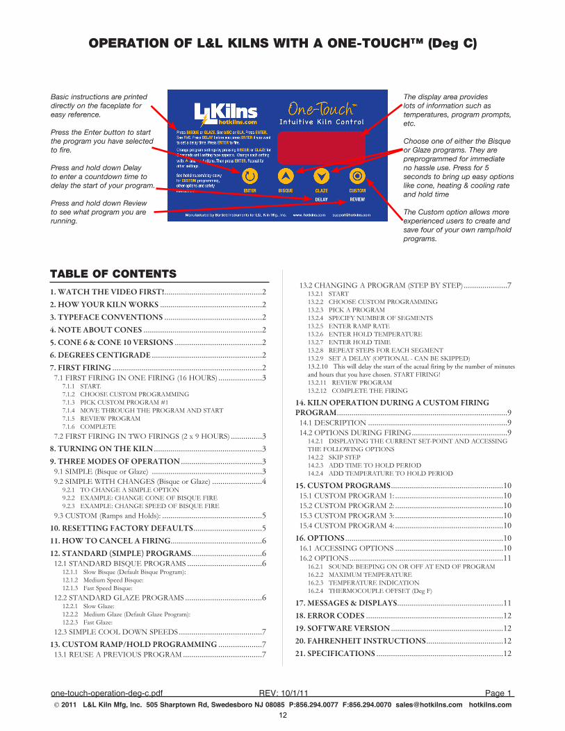
Basic instructions are printed directly on the faceplate for easy reference.
Press the Enter button to start the program you have selected to fire.
Press and hold down Delay to enter a countdown time to delay the start of your program.
Press and hold down Review to see what program you are running.
The display area provides lots of information such as temperatures, program prompts, etc.
Choose one of either the Bisque or Glaze programs. They are preprogrammed for immediate no hassle use. Press for 5 seconds to bring up easy options like cone, heating & cooling rate and hold time
The Custom option allows more experienced users to create and save four of your own ramp/hold programs.
TABLE OF CONTENTS
1. WATCH THE VIDEO FIRST!................................................22. HOW YOUR KILN WORKS..................................................23. TYPEFACE CONVENTIONS................................................24. NOTE ABOUT CONES..........................................................25. CONE 6 & CONE 10 VERSIONS...........................................26. DEGREES CENTIGRADE......................................................27. FIRST FIRING.........................................................................2
7.1 FIRST FIRING IN ONE FIRING (16 HOURS)......................37.1.1 START. 7.1.2 CHOOSE CUSTOM PROGRAMMING7.1.3 PICK CUSTOM PROGRAM #17.1.4 MOVE THROUGH THE PROGRAM AND START7.1.5 REVIEW PROGRAM7.1.6 COMPLETE
7.2 FIRST FIRING IN TWO FIRINGS (2 x 9 HOURS)................38. TURNING ON THE KILN.....................................................39. THREE MODES OF OPERATION........................................3
9.1 SIMPLE (Bisque or Glaze) ......................................................39.2 SIMPLE WITH CHANGES (Bisque or Glaze).........................4
9.2.1 TO CHANGE A SIMPLE OPTION9.2.2 EXAMPLE: CHANGE CONE OF BISQUE FIRE9.2.3 EXAMPLE: CHANGE SPEED OF BISQUE FIRE
9.3 CUSTOM (Ramps and Holds):.................................................510. RESETTING FACTORY DEFAULTS..................................511. HOW TO CANCEL A FIRING............................................612. STANDARD (SIMPLE) PROGRAMS...................................6
12.1 STANDARD BISQUE PROGRAMS.....................................612.1.1 Slow Bisque (Default Bisque Program):12.1.2 Medium Speed Bisque:12.1.3 Fast Speed Bisque:
12.2 STANDARD GLAZE PROGRAMS......................................612.2.1 Slow Glaze:12.2.2 Medium Glaze (Default Glaze Program):12.2.3 Fast Glaze:
12.3 SIMPLE COOL DOWN SPEEDS.........................................713. CUSTOM RAMP/HOLD PROGRAMMING......................7
13.1 REUSE A PREVIOUS PROGRAM.......................................7
13.2 CHANGING A PROGRAM (STEP BY STEP)......................713.2.1 START13.2.2 CHOOSE CUSTOM PROGRAMMING13.2.3 PICK A PROGRAM13.2.4 SPECIFY NUMBER OF SEGMENTS13.2.5 ENTER RAMP RATE13.2.6 ENTER HOLD TEMPERATURE13.2.7 ENTER HOLD TIME13.2.8 REPEAT STEPS FOR EACH SEGMENT13.2.9 SET A DELAY (OPTIONAL - CAN BE SKIPPED)13.2.10...This.will.delay.the.start.of.the.actual.firing.by.the.number.of.minutes.and.hours.that.you.have.chosen..START FIRING! 13.2.11 REVIEW PROGRAM13.2.12 COMPLETE THE FIRING
14. KILN OPERATION DURING A CUSTOM FIRING PROGRAM...................................................................................9
14.1 DESCRIPTION....................................................................914.2 OPTIONS DURING FIRING...............................................9
14.2.1 DISPLAYING THE CURRENT SET-POINT AND ACCESSING THE FOLLOWING OPTIONS14.2.2 SKIP STEP14.2.3 ADD TIME TO HOLD PERIOD14.2.4 ADD TEMPERATURE TO HOLD PERIOD
15. CUSTOM PROGRAMS.......................................................1015.1 CUSTOM PROGRAM 1:.....................................................1015.2 CUSTOM PROGRAM 2:.....................................................1015.3 CUSTOM PROGRAM 3:.....................................................1015.4 CUSTOM PROGRAM 4:.....................................................10
16. OPTIONS.............................................................................1016.1 ACCESSING OPTIONS.....................................................1016.2 OPTIONS...........................................................................11
16.2.1 SOUND: BEEPING ON OR OFF AT END OF PROGRAM16.2.2 MAXIMUM TEMPERATURE16.2.3 TEMPERATURE INDICATION16.2.4 THERMOCOUPLE OFFSET (Deg F)
17. MESSAGES & DISPLAYS....................................................1118. ERROR CODES...................................................................1219. SOFTWARE VERSION.......................................................1220. FAHRENHEIT INSTRUCTIONS......................................1221. SPECIFICATIONS..............................................................12
12
OPERATION OF L&L KILNS WITH A ONE-TOUCH™ (Deg C)
one-touch-operation-deg-c,pdf REV:10/1/11 Page2 2011 L&L Kiln Mfg, Inc. 505 Sharptown Rd, Swedesboro NJ 08085 P:856.294.0077 F:856.294.0070 [email protected] hotkilns.com
1. WATCH THE VIDEO FIRST!We.highly. recommend.watching. the.video.before.you.read.this.instruction.manual.for.quicker.understanding.of. how. this. great. control. works.. Go to hotkilns.com/one-touch-video
2. HOW YOUR KILN WORKSThe.One-Touch™.Intuitive.Kiln.Control.was.designed.for. busy. school. teachers,. contemporary. studios,. and.hobbyists.. No. programming. is. necessary. -. simple.adjustments.are.easy,.yet.sophisticated.programming.is.also.easy..
The. One-Touch. automatic. program. control. uses. one.thermocouple.to.measure.the.temperature.of.the.kiln.
The. control. automatically. adjusts. power. by. turning.power.contactors.on.and.off. to.control. the.heat.up.of.the.kiln.according.to.the.program.you.are.firing.
The.preprogrammed.Bisque.and.Glaze.programs.are.set.to.fire.to.the.most.universally.accepted.versions.of.these.programs,.which.makes.firing.basic.ceramics.easy..These.are.a.slow bisque to Cone 04.and.a.Medium Glaze to Cone 06.
There. are. three. modes. of. operation:. Simple. (just.the. basic. Bisque. and. Glaze. programs. as. mentioned.above);. Simple. with. Changes. (you. can. adjust. a. few.basic.parameters. like.heat.up. speed,. cool.down.speed,.candling. time. at. a. low. temperature,. and. the. cone. to.fire.to),.and.Custom.where.you.program.all.ramps.and.holds.yourself.
3. TYPEFACE CONVENTIONS1.. Typeface. font:. CUSTOM indicates. a. Button. on. the.
control.
2.. Typeface.font:.CUS1 indicates.what.you.see.in.the.display.
4. NOTE ABOUT CONESCones. measure. “heat. work”. rather. than. just. final. set.point. temperature.. It. is. like.baking.a. turkey..You.can.bake. it. slow. at. a. low. temperature. or. bake. it. fast. at. a.high.temperature..
The. One-Touch™. control. adjusts. the. final. set. point.temperature.based.on.the.actual.final.ramp.rate.of.the.kiln.(in.the.last.segment.of.any.program)..It.does.this.to.achieve.a.particular.result.(which.is.the.correct.bending.of.the.cone).rather.than.a.particular.final.temperature..
For a full explanation of cones go to hotkilns.com/what-cone-numbers-mean
If.you.want.to.see.the.Orton.Cone.Chart.go.to. hotkilns.com/orton-cone-chart.
Note: you can adjust how the kiln fires by adjusting the thermocouple offset. For instance, if your kiln is firing cool (according to a witness cone placed in the kiln) then you can add positive Offset. If it is firing hot then you can reduce the offset or put in a negative offset. See the OPTIONS section for instructions on how to do this.
5. CONE 6 & CONE 10 VERSIONSThere are two versions of the control: Cone 6 and Cone 10. The Cone 6 versions are used on the School-Master kilns to limit the maximum temperature of the kiln. Liberty-Belle, Doll, Fuego and Robin kilns use the Cone 10 version. There are only minor differences as noted in these instructions. The main issue is the maximum temperature that the control will let the kiln go to.
6. DEGREES CENTIGRADEYour.control.comes.set.up.to.display.Degrees.Centigrade..This. can. easily. be. changed. to. display. in. Degrees.Fahrenheit.(see.the.OPTIONS.section).
7. FIRST FIRINGThree.of.the.CUSTOM.programs.have.been.programmed.by.the.factory.to.simplify.the.first.firing.process..
Once. this. process. has. been. completed. they. may. be.reprogrammed.at.will..
See the separate PDF called “FIRST FIRING INSTRUCTIONS FOR L&L KILNS WITH A ONE-TOUCH” Go to hotkilns.com/first-firing-one-touch-control. This will also be found in your complete instruction manual.
13
OPERATION OF L&L KILNS WITH A ONE-TOUCH™ (Deg C)
one-touch-operation-deg-c,pdf REV:10/1/11 Page3 2011 L&L Kiln Mfg, Inc. 505 Sharptown Rd, Swedesboro NJ 08085 P:856.294.0077 F:856.294.0070 [email protected] hotkilns.com
7.1 FIRST FIRING IN ONE FIRING (16 HOURS)
7.1.1 START. 1.. Start.with. the.display. reading.IdLE. and. flashing. a.
temperature.or.StOP.and.temperature.
7.1.2 CHOOSE CUSTOM PROGRAMMING1.. Press.CUSTOM
2.. See CUSt
3.. Press.ENTER
7.1.3 PICK CUSTOM PROGRAM #11.. You. will. see. CUS1,. CUS2,. CUS3. or. CUS4..
These.are.the.four.custom.programs..
2.. Scroll.to.CUS1.with.the.UP.and.DOWN.button.
3.. Select.CUS1.by.pressing.the.ENTER.button.
7.1.4 MOVE THROUGH THE PROGRAM AND START1.. Press.ENTER for. each.display.prompt. that. you. see. as.
the.control.scrolls.through.the.enter.CUS1.program. until.you.see.FIrE.
2.. Press. ENTER again. when. you. see. FIrE. and. the.One-Touch.control.will.start.firing.the.kiln.using.the.CUS1.program..
3.. You.will.know.it.is.firing.because.the.display.just.reads.the. kiln. temperature. steadily.. You. will. probably. also.hear.the.relays.clicking.on.and.off.
4.. There. is. a. list. of. Preprogrammed. Custom. Programs.later.in.this.manual.which.will.show.you.a.list.of.values.for.CUS1 you.see.while.pressing.ENTER.
7.1.5 REVIEW PROGRAM1.. Press.the.REVIEW.button.to.review.the.program..
2.. You. can. do. this. when. you. see. the.FIrE. display,.CUS1,. CUS2,. CUS3,. CUS4. or. while. firing.(when.you.see.the.kiln.temperature)..
3.. The.display.will.scroll.though.the.name.of.the.program.(i.e..CUS4),. then. the.number.of. segments,. then.all.the.ramps,.temperatures.and.holds.in.sequence..
4.. The.display. changes. rapidly. so. you.may.have. review.more.than.once.to.see.everything.
7.1.6 COMPLETE1.. When.the.program.is.complete,.you.will.see.CPLt.
2.. If.the.Beep.option.has.been.turned.to.“On”.then.the.control.will.beep.about.15. times.. If. the.beep.option.
is.set.for.“OFF,”.then.there.is.no.sound..If.the.beep.option.is.set.for.“FULL,”.the.control.will.beep.until.any.button.is.pressed..See.the.OPTIONS.section.for.how.to.change.this.option.
7.2 FIRST FIRING IN TWO FIRINGS (2 x 9 HOURS)
1.. Go. through. the. above. process. but. do. it. in. two.programs..It.works.the.same.as.above.except.that.you.run.the.two.separate.programs.at.different.times.
2.. CUS2 is. the. first.program.and. that. takes. about.9.hours.
3.. CUS3 is. the. second. program. and. that. also. takes.about.9.hours.
4.. See.the.list.of.Preprogrammed.Custom.Programs.later.in.this.manual.for.a.list.of.values.you.see.while.pressing.ENTER.
8. TURNING ON THE KILN1.. Make.sure.your.circuit.breaker.or.fused.disconnect.
switch.is.turned.on.and.the.kiln.is.plugged.in.
2.. Turn.on.kiln.with.the.toggle.On/Off.switch.on.the.control.box.
3.. You.will.see.a.software.code.flash.briefly..Then.you.will.see.either.IdLE or StOP alternating.with.a.display.of.the.current.kiln.temperature.
9. THREE MODES OF OPERATION
9.1 SIMPLE (Bisque or Glaze) 1.. Press.one.of.two.buttons.marked.BISQUE.and.GLAZE.
2.. You.will.then.see.either.bISC.or.GLA.depending.on.which.button.you.pressed..
3.. The.bISC.is.a.slow.bisque.to.Cone.04..The.GLA.is.a.medium.glaze.to.Cone.06.
4.. Press.ENTER.and.the.display.reads.FIrE..
5.. You. can. add. a. delay. time. to. the. program. by.pressing.the.DOWN.arrow.when.you.see.FIrE.but.before.you.press.ENTER..
6.. After. you. press. the. DELAY. button,. you. will. see.dELA.flashing.with.a.time.value,.typically.00.00.which.represents.00.hours.and.00.minutes..
14
OPERATION OF L&L KILNS WITH A ONE-TOUCH™ (Deg C)
one-touch-operation-deg-c,pdf REV:10/1/11 Page4 2011 L&L Kiln Mfg, Inc. 505 Sharptown Rd, Swedesboro NJ 08085 P:856.294.0077 F:856.294.0070 [email protected] hotkilns.com
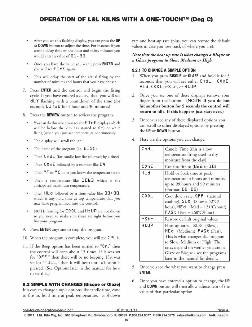
•. After.you.see.this.flashing.display,.you.can.press.the.UP.or.DOWN.button.to.adjust.the.time..For.instance.if.you.want.a.delay.time.of.one.hour.and.thirty.minutes.you.would.enter.a.value.of.01.30.
•. Once.you.have.the.value.you.want,.press.ENTER.and.you.will.see.FIrE.again.
•. This. will. delay. the. start. of. the. actual. firing. by. the.number.of.minutes.and.hours.that.you.have.chosen.
7.. Press. ENTER. and. the. control. will. begin. the. firing.cycle..If.you.have.entered.a.delay,.then.you.will.see.dLY. flashing. with. a. countdown. of. the. time. (for.example.01:30.for.1.hour.and.30.minutes)
8.. Press.the.REVIEW.button.to.review.the.program..
•. You.can.do.this.when.you.see.the.FIrE.display.(which.will. be. before. the. kiln. has. started. to. fire). or. while.firing.(when.you.just.see.temperature.continuously..
•. The.display.will.scroll.though:
•. The.name.of.the.program.(i.e..bISC)
•. Then.CndL.(for.candle.low.fire.followed.by.a.time)
•. Then.COnE.followed.by.a.number.like.04
•. Then.°F.or.°C.to.let.you.know.the.temperature.scale
•. Then. a. temperature. like. 1063. which. is. the.anticipated.maximum.temperature..
•. Then.HLd. followed. by. a. time. value. like.00:00,.which. is. any. hold. time. at. top. temperature. that. you.may.have.programmed.into.the.control.
•. NOTE:.Setting.for.COOL.and.HtUP.are.not.shown.so. you.need. to.make. sure. these. are. right. before. you.fire.your.program.
9.. Press.ENTER.anytime.to.stop.the.program.
10.. When.the.program.is.complete,.you.will.see.CPLt.
11.. If.the.Beep.option.has.been.turned.to.“On,”.then.the.control.will.beep.about.15. times.. If. it.was. set.for.“OFF,”.then.there.will.be.no.beeping..If.it.was.set.for.“FULL,”.then.it.will.beep.until.a.button.is.pressed..(See.Options. later. in.the.manual.for.how.to.set.this.)
9.2 SIMPLE WITH CHANGES (Bisque or Glaze)It.is.easy.to.change.simple.options.like.candle.time,.cone.to. fire. to,. hold. time. at. peak. temperature,. . cool-down.
rate.and.heat-up.rate.(plus,.you.can.restore.the.default.values.in.case.you.lose.track.of.where.you.are)..
Note that the heat up rate is what changes a Bisque or a Glaze program to Slow, Medium or High.
9.2.1 TO CHANGE A SIMPLE OPTION1.. When.you.press.BISQUE.or.GLAZE.and.hold.it.for.5.
seconds,. then.you.will. see.either.CndL, COnE,.HLd,.COOL,.rStr,.or.HtUP.
2.. Once. you. see. one. of. these. displays. remove. your.finger. from. the. button.. . (NOTE: If you do not hit another button for 5 seconds the control will return to idle. If this happens just start over.)
3.. Once.you.see.any.of.these.displayed.options.you.can.scroll.to.other.displayed.options.by.pressing.the.UP.or.DOWN.button.
4.. Here.are.the.options.you.can.change:
CndL Candle.Time.(this.is.a.low.temperature.firing.used.to.dry.moisture.from.the.clay)
COnE Cone.to.fire.to.(022.to.10)HLd Hold.or.Soak.time.at.peak.
temperature.in.hours.and.minutes.up.to.99.hours.and.99.minutes.(Format:.00.00)
COOL Cool.down.rate..OFF (natural.cooling),.SLO (Slow.=.52°C/hour),.MEd (Med.=.121°C/hour),.FASt.(Fast.=.260°C/hour)
rStr Restore.default.original.valuesHtUP Heat.up.rates. SLO (Slow),.
MEd (Medium),.FASt.(Fast)..This.is.what.changes.the.program.to.Slow,.Medium.or.High..The.rates.depend.on.wether.you.are.in.Glaze.or.Bisque.-.see.the.programs.later.in.the.manual.for.details.
5.. Once.you.see.the.what.you.want.to.change.press.ENTER.
6.. Once.you.have.entered.a.option.to.change,.the.UP.and.DOWN.button.will.then.allow.adjustment.of.the.value.of.that.particular.option.
15
OPERATION OF L&L KILNS WITH A ONE-TOUCH™ (Deg C)
one-touch-operation-deg-c,pdf REV:10/1/11 Page5 2011 L&L Kiln Mfg, Inc. 505 Sharptown Rd, Swedesboro NJ 08085 P:856.294.0077 F:856.294.0070 [email protected] hotkilns.com
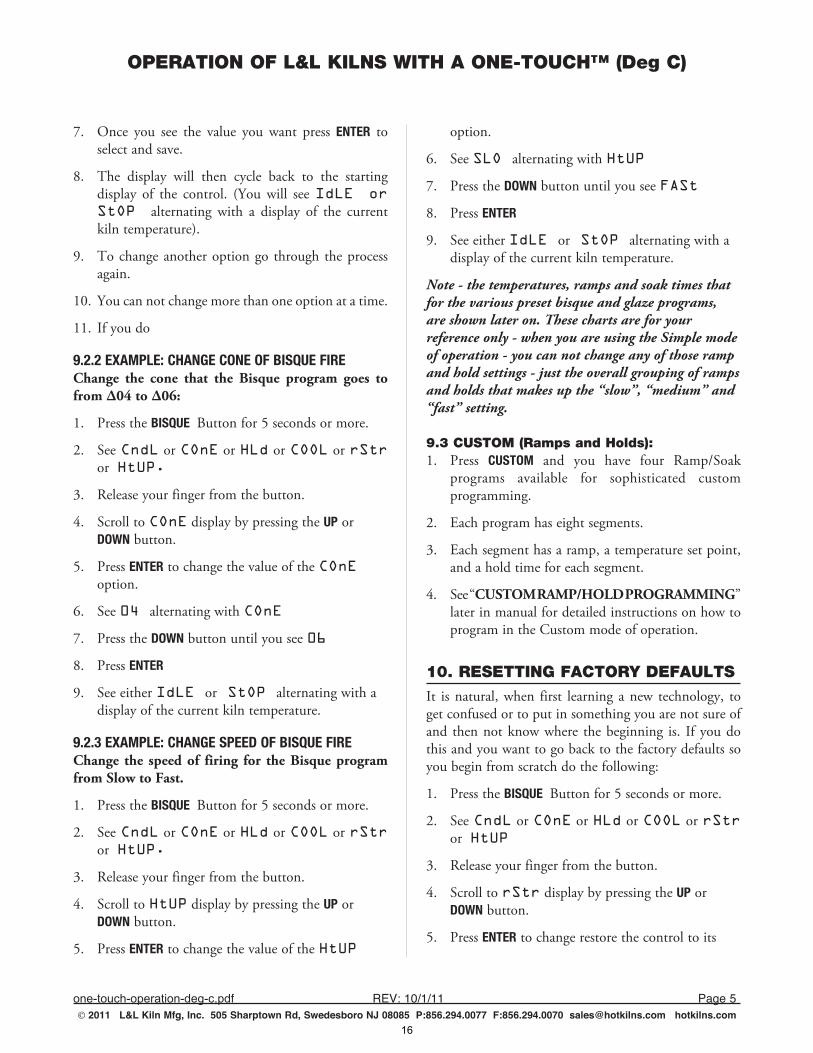
7.. Once. you. see. the. value. you. want. press. ENTER. to.select.and.save.
8.. The. display. will. then. cycle. back. to. the. starting.display. of. the. control.. (You. will. see.IdLE or StOP alternating. with. a. display. of. the. current.kiln.temperature).
9.. To.change.another.option.go. through. the.process.again..
10.. You.can.not.change.more.than.one.option.at.a.time.
11.. If.you.do.
9.2.2 EXAMPLE: CHANGE CONE OF BISQUE FIREChange the cone that the Bisque program goes to from ∆04 to ∆06:
1.. Press.the.BISQUE Button.for.5.seconds.or.more.
2.. See.CndL.or.COnE.or.HLd.or.COOL.or.rStr.or..HtUP.
3.. Release.your.finger.from.the.button.
4.. Scroll.to.COnE.display.by.pressing.the.UP.or.DOWN.button.
5.. Press.ENTER.to.change.the.value.of.the.COnE option.
6.. See.04 alternating.with.COnE
7.. Press.the.DOWN.button.until.you.see.06
8.. Press.ENTER
9.. See.either.IdLE or StOP alternating.with.a.display.of.the.current.kiln.temperature.
9.2.3 EXAMPLE: CHANGE SPEED OF BISQUE FIREChange the speed of firing for the Bisque program from Slow to Fast.
1.. Press.the.BISQUE Button.for.5.seconds.or.more.
2.. See.CndL.or.COnE.or.HLd.or.COOL.or.rStr.or..HtUP.
3.. Release.your.finger.from.the.button.
4.. Scroll.to.HtUP.display.by.pressing.the.UP.or.DOWN.button.
5.. Press.ENTER.to.change.the.value.of.the.HtUP
option.
6.. See.SLO alternating.with.HtUP
7.. Press.the.DOWN.button.until.you.see.FASt
8.. Press.ENTER
9.. See.either.IdLE or StOP alternating.with.a.display.of.the.current.kiln.temperature.
Note - the temperatures, ramps and soak times that for the various preset bisque and glaze programs, are shown later on. These charts are for your reference only - when you are using the Simple mode of operation - you can not change any of those ramp and hold settings - just the overall grouping of ramps and holds that makes up the “slow”, “medium” and “fast” setting.
9.3 CUSTOM (Ramps and Holds):1.. Press. CUSTOM. and. you. have. four. Ramp/Soak.
programs. available. for. sophisticated. custom.programming..
2.. Each.program.has.eight.segments.
3.. Each.segment.has.a.ramp,.a.temperature.set.point,.and.a.hold.time.for.each.segment..
4.. See.“CUSTOM RAMP/HOLD PROGRAMMING”.later.in.manual.for.detailed.instructions.on.how.to.program.in.the.Custom.mode.of.operation.
10. RESETTING FACTORY DEFAULTSIt. is.natural,.when. first. learning. a.new. technology,. to.get.confused.or.to.put.in.something.you.are.not.sure.of.and. then.not.know.where. the.beginning. is.. If. you.do.this.and.you.want.to.go.back.to.the.factory.defaults.so.you.begin.from.scratch.do.the.following:
1.. Press.the.BISQUE Button.for.5.seconds.or.more.
2.. See.CndL.or.COnE.or.HLd.or.COOL.or.rStr.or..HtUP
3.. Release.your.finger.from.the.button.
4.. Scroll.to.rStr.display.by.pressing.the.UP.or.DOWN.button.
5.. Press.ENTER.to.change.restore.the.control.to.its.
16
OPERATION OF L&L KILNS WITH A ONE-TOUCH™ (Deg C)
one-touch-operation-deg-c,pdf REV:10/1/11 Page6 2011 L&L Kiln Mfg, Inc. 505 Sharptown Rd, Swedesboro NJ 08085 P:856.294.0077 F:856.294.0070 [email protected] hotkilns.com
factory.default.values
6.. See.either.IdLE or StOP alternating.with.a.display.of.the.current.kiln.temperature.
7.. Repeat.the.same.process.for.GLAZE
11. HOW TO CANCEL A FIRING1.. Just.press.ENTER while.the.kiln.is.firing..
2.. You.will.see.either.IdLE or StOP alternating.with.a.display.of.the.current.kiln.temperature.
12. STANDARD (SIMPLE) PROGRAMS1. The following tables show you exactly how the
control is set up so you can understand what is going on “under the hood”.
2. You can not change the way the ramps, holds and temperature set points are set - if you need or want to do that then you need to use Custom Programming.
3. The “Default Bisque Program” is a Slow Bisque and the “Default Glaze Program” is a Medium Glaze.
4. “Slow”, “Medium” and “Fast” refer to the ramp speeds and lengths of the programs.
5. When you change the speed of the Cooldown this goes from OFF (no controlled cooling or no heat at all when cooling), to FASt (Fast = 260°C/hour) MEd (Medium = 121°C/hour) to SLO (Slow = 52°C/hour).
6. We recommend experimenting with slower cooldowns for interesting effects on glazing. It is usually irrelevant for bisquing.
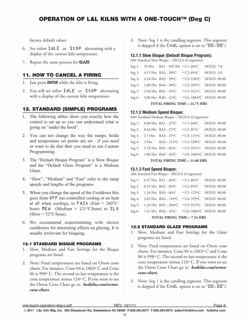
12.1 STANDARD BISQUE PROGRAMS1.. Slow,. Medium. and. Fast. Settings. for. the. Bisque.
programs.are.listed.
2.. Note:.Final.temperatures.are.based.on.Orton.cone.charts..For.instance,.Cone.04.is.1063º.C.and.Cone.06.is.998º.C..The.second-to-last.temperature.is.the.cone.temperature.minus.124º.C..If.you.want.to.see.the.Orton.Cone.Chart.go.to. hotkilns.com/orton-cone-chart.
3.. Note:.Seg.1.is.the.candling.segment..This.segment.is.skipped.if.the.CndL.option.is.set.to.“00.00”).
12.1.1 Slow Bisque (Default Bisque Program):∆04.Standard.Slow.Bisque.–.SEGS-6.(6.segments)
Seg.1-. 10.Hrs. RA1.-.4ºC/Hr.. º.C1–66ºC.. HOLD-.7.0
Seg.2-. 4.15.Hrs..RA2.-.38ºC.. º.C2–85ºC. HOLD-.3.0
Seg.3-... 4.10.Hrs..RA3.-.93ºC. º.C3–538ºC.. HOLD-.00.00
Seg.4-... 1.00.Hrs..RA4.-.38ºC.. º.C4–593ºC.. HOLD-.00.00
Seg.5-... 2.50.Hrs..RA5.-.93ºC. º.C5–921ºC.. HOLD-.00.00
Seg.6-... 3.00.Hrs..RA6.-.42ºC. º.C6–1063ºC. HOLD-.00.00
TOTAL FIRING TIME = 24.75 HRS
12.1.2 Medium Speed Bisque:∆04.Standard.Medium.Bisque.–.SEGS-6.(6.segments)
Seg.1-. 0.88.Hrs..RA1.-.27ºC.. º.C1–66ºC.. HOLD-.00.00
Seg.2-. 0.44.Hrs..RA2.-.27ºC.. º.C2–85ºC... HOLD-.00.00
Seg.3-. 2.5.Hrs.. RA3.-.27ºC.. º.C3–121ºC.. HOLD-.00.00
Seg.4-. 3.Hrs.. RA4.-.121ºC.. º.C4–538ºC... HOLD-.00.00
Seg.5-... 3.78.Hrs..RA5.-.82ºC. º.C5–921ºC.. HOLD-.00.00
Seg.6-... 1.00.Hrs..RA6.-.42ºC.. º.C6–1063ºC.. HOLD-.00.00
TOTAL FIRING TIME = 11.60 HRS
12.1.3 Fast Speed Bisque:∆04.Standard.Fast.Bisque.–.SEGS-6.(6.segments)
Seg.1-. 0.47.Hrs..RA1.-.66ºC.. º.C1–66ºC.. HOLD-.00.00
Seg.2-. 0.23.Hrs..RA2.-.66ºC.. º.C2–85ºC... HOLD-.00.00
Seg.3-. 1.26.Hrs..RA3.-.66ºC.. º.C3–121ºC... HOLD-.00.00
Seg.4-. 2.83.Hrs..RA4.-.149ºC.. º.C4–593ºC... HOLD-.00.00
Seg.5-... 1.34.Hrs..RA5.-.204ºC. º.C5–921ºC.. HOLD-.00.00
Seg.6-... 1.41.Hrs..RA6.-.42ºC.. º.C6–1063ºC.. HOLD-.00.00
TOTAL FIRING TIME = 7.54 HRS
12.2 STANDARD GLAZE PROGRAMS1.. Slow,. Medium. and. Fast. Settings. for. the. Glaze.
programs.are.listed.
2.. Note:.Final.temperatures.are.based.on.Orton.cone.charts..For.instance,.Cone.04.is.1063º.C.and.Cone.06.is.998º.C..The.second-to-last.temperature.is.the.cone.temperature.minus.124º.C..If.you.want.to.see.the.Orton.Cone.Chart.go.to. hotkilns.com/orton-cone-chart.
3.. Note:.Seg.1.is.the.candling.segment..This.segment.is.skipped.if.the.CndL.option.is.set.to.“00.00”).
17
OPERATION OF L&L KILNS WITH A ONE-TOUCH™ (Deg C)
one-touch-operation-deg-c,pdf REV:10/1/11 Page7 2011 L&L Kiln Mfg, Inc. 505 Sharptown Rd, Swedesboro NJ 08085 P:856.294.0077 F:856.294.0070 [email protected] hotkilns.com
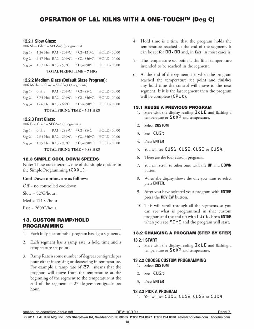
12.2.1 Slow Glaze:∆06.Slow.Glaze.–.SEGS–3.(3.segments)
Seg.1-. 1.26.Hrs..RA1.-.204ºC.. º.C1–121ºC... HOLD-.00.00
Seg.2-. 4.17.Hrs..RA2.-.204ºC.. º.C2–856ºC... HOLD-.00.00
Seg.3-... 1.57.Hrs..RA3.-.53ºC.. º.C3–998ºC.. HOLD-.00.00
TOTAL FIRING TIME = 7 HRS
12.2.2 Medium Glaze (Default Glaze Program):∆06.Medium.Glaze.–.SEGS–3.(3.segments)
Seg.1-. 0.Hrs. RA1.-.204ºC.. º.C1–85ºC... HOLD-.00.00
Seg.2-. 3.75.Hrs..RA2.-.204ºC.. º.C1–856ºC... HOLD-.00.00
Seg.3-. 1.66.Hrs..RA3.-.66ºC.. º.C2–998ºC... HOLD-.00.00
TOTAL FIRING TIME = 5.41 HRS
12.2.3 Fast Glaze:∆06.Fast.Glaze.–.SEGS–3.(3.segments)
Seg.1-. 0.Hrs. RA1.-.299ºC.. º.C1–85ºC... HOLD-.00.00
Seg.2-. 2.63.Hrs..RA2.-.299ºC.. º.C2–856ºC... HOLD-.00.00
Seg.3-. 1.25.Hrs..RA3.-.93ºC.. º.C3–998ºC... HOLD-.00.00
TOTAL FIRING TIME = 3.88 HRS
12.3 SIMPLE COOL DOWN SPEEDSNote:.These.are.entered.as.one.of.the.simple.options.in.the.Simple.Programming.(COOL)..
Cool Down options are as follows:
Off.=.no.controlled.cooldown
Slow.=.52°C/hour
Med.=.121°C/hour
Fast.=.260°C/hour
13. CUSTOM RAMP/HOLD PROGRAMMING1.. Each.fully.customizable.program.has.eight.segments.
2.. Each. segment.has. a. ramp. rate,. a.hold. time. and. a.temperature.set.point.
3.. Ramp.Rate.is.some.number.of.degrees.centigrade.per.hour.either.increasing.or.decreasing.in.temperature..For. example. a. ramp. rate. of.27 means. that. the.program. will. move. from. the. temperature. at. the.beginning.of.the.segment.to.the.temperature.at.the.end. of. the. segment. at. 27. degrees. centigrade. per.hour..
4.. Hold. time. is. a. time. that. the. program. holds. the.temperature. reached.at. the.end.of. the. segment.. It.can.be.set.for.00.00.and,.in.fact,.in.most.cases.is.
5.. The.temperature.set.point.is.the.final.temperature.intended.to.be.reached.in.the.segment.
6.. At. the.end.of. the.segment,. i.e..when.the.program.reached. the. temperature. set. point. and. finishes.any. hold. time. the. control. will. move. to. the. next.segment..If.it.is.the.last.segment.then.the.program.will.be.complete.(CPLt).
13.1 REUSE A PREVIOUS PROGRAM1.. Start.with. the.display. reading.IdLE. and. flashing. a.
temperature.or.StOP.and.temperature.
2.. Select.CUSTOM
3.. See CUSt
4.. Press.ENTER.
5.. You.will.see.CUS1,.CUS2,.CUS3.or.CUS4..
6.. These.are.the.four.custom.programs..
7.. You.can. scroll. to.other.ones.with. the.UP. and.DOWN.button..
8.. When. the. display. shows. the. one. you. want. to. select.press.ENTER.
9.. After.you.have.selected.your.program.with.ENTER.press.the.REVIEW.button.
10.. This.will. scroll. through.all. the. segments. so.you.can. see. what. is. programmed. in. that. custom.program.and.the.end.up.with.FIrE..Press.ENTER.when.you.see.FIrE.and.the.program.will.start..
13.2 CHANGING A PROGRAM (STEP BY STEP)
13.2.1 START1.. Start.with. the.display. reading.IdLE. and. flashing. a.
temperature.or.StOP.and.temperature.
13.2.2 CHOOSE CUSTOM PROGRAMMING1.. Select.CUSTOM
2.. See CUSt
3.. Press.ENTER.
13.2.3 PICK A PROGRAM1.. You.will.see.CUS1,.CUS2,.CUS3.or.CUS4..
18
OPERATION OF L&L KILNS WITH A ONE-TOUCH™ (Deg C)
one-touch-operation-deg-c,pdf REV:10/1/11 Page8 2011 L&L Kiln Mfg, Inc. 505 Sharptown Rd, Swedesboro NJ 08085 P:856.294.0077 F:856.294.0070 [email protected] hotkilns.com
2.. These.are.the.four.custom.programs..
3.. You.can. scroll. to.other.ones.with. the.UP. and.DOWN.button..
4.. When. the. display. shows. the. one. you. want. to. select.press.ENTER.
13.2.4 SPECIFY NUMBER OF SEGMENTS1.. Once.you.have.chosen.a.program,.you.need.to.specify.
the.total.number.of.segments.that.you.will.use...
2.. All.programs.consist.of.1.or.more.segments,.as.shown.in.the.sample.profiles.in.this.manual..
3.. Each. segment. has. 3. parts:. a. ramp. rate. (speed. of.temperature.rise.in.degrees.centigrade.per.hour),.hold.temperature.(in.degrees.centigrade),.and.hold.time.(in.hours.and.minutes).at.the.hold.temperature...
4.. It. is. helpful. to. draw. your. profile. to. see. how. many.segments.you.will.need...
5.. Then,.use. the.UP. and.DOWN. .buttons. to.display. the.desired.number.of.segments,.and.press.ENTER.to.store.the.value.when.you.see.the.number.you.want.
13.2.5 ENTER RAMP RATE1.. You.will.see.rA1,.followed.by.a.value.like.150..
2.. The.rA1.stands.for.Ramp.One..
3.. The.value.represents.a.rate.of.temperature.rise.expressed.in.degrees.per.hour...
4.. Use. the. arrow. buttons. to. adjust. the. rate. and. press.ENTER.to.store.the.value.
5.. To.help.you.visualize.what.is.typical.of.various.ramps.read.the.following:
•. Slow.rates.range.from.1-50.degrees.per.hour,.and.are.used.for.thick.glass.projects...
•. Medium.rates.range.from.60.to.200.degrees.per.hour,.and.are.used.for.thick,.hand-built.ceramics...
•. Fast. rates. range. from. 250–1000. degrees. per. hour,.and.are.used.for.glazes,.thin.ceramics.and.small.glass.projects...
6.. A. rate. of. 9999. sets. the. kiln. to. ramp. as. fast. as.possible..
7.. Also,.see.the.various.ramps.in.the.standard.programs.for.an.idea.of.what.works.
13.2.6 ENTER HOLD TEMPERATURE1.. You.will.see.oC1 followed.by.a.value.like.0300..
2.. The.oC1 stands.for.Temperature.One..
3.. For. a. single. segment. program,. this. is. the. top.temperature.of.the.firing...
4.. For.multi-segment.programs,.this.can.be.a.temperature.where.you.want.to.hold.to.dry.the.ware.or.for.carbon.burn-out,. or. to. equalize. the. temperature. across. the.item.or.it.can.be.where.you.just.want.to.switch.ramp.rates.without.a.hold...
5.. Adjust. the. temperature. with. the. UP. and. DOWN..buttons.and.press.ENTER.to.store.the.displayed.value.
13.2.7 ENTER HOLD TIME1.. You.will.see.HLd1 followed.by.a.value.like.00:00..
2.. The.HLd1.stands.for.Hold.One..
3.. Hours. are. displayed. to. the. left. of. the. decimal. point.and.minutes.to.the.right.(HH.mm)...
4.. Use.the.he.UP.and.DOWN..buttons..to.adjust.the.hold.time.at.the.soak.temperature...
5.. Use. a. zero. (00.00). hold. time. if. you. just.want. to.move.to.the.next.segment...
6.. Drying. ware. can. take. several. hours,. while. holds. at.peak.temperature.usually.range.10–15.minutes.to.even.out.the.kiln..Feel.free.to.experiment.-.there.is.no.one.right.way.to.program.a.kiln.
13.2.8 REPEAT STEPS FOR EACH SEGMENT1.. For. segment. two,. the. display. will. read.rA2,.oC2
and HLd2
2.. For.segment.three,. the.display.will. read.rA3,.oC3 and HLd3 etc.
13.2.9 SET A DELAY (OPTIONAL - CAN BE SKIPPED)1.. If. you. want. to. set. a. delay,. you. can. do. it. when. the.
display.says.FIrE..
2.. You.can.add.a.delay.time.to.the.program.by.pressing.the.DOWN.arrow.when.you.see.FIrE.but.before.you.press.ENTER..
3.. After.you.press.the.DELAY.button.you.will.see.dELA.flashing. with. a. time. value,. typically.00.00. which.represents.00.hours.and.00.minutes..
4.. After.you.see.this.flashing.display,.you.can.press.the.UP.or.DOWN.button.to.adjust.the.delay.time..
19
OPERATION OF L&L KILNS WITH A ONE-TOUCH™ (Deg C)
one-touch-operation-deg-c,pdf REV:10/1/11 Page9 2011 L&L Kiln Mfg, Inc. 505 Sharptown Rd, Swedesboro NJ 08085 P:856.294.0077 F:856.294.0070 [email protected] hotkilns.com
5.. Once.you.see.the.value.you.want,.press.ENTER.and.you.will.see.FIrE.again..
13.2.10.This.will.delay.the.start.of.the.actual.firing.by.the.number.of.minutes.and.hours.that.you.have.chosen..START FIRING!
1.. The.display.will.show.FIrE.(ready.to.fire).when.all.segments.have.been.entered...
2.. Press.ENTER.to.start.the.firing.
Caution should be taken to make sure that no one can place anything around or on the kiln during the delay start. Treat the kiln as firing during the delay start.
13.2.11 REVIEW PROGRAM1.. Press.the.REVIEW.button.to.review.the.program..
2.. You. can. do. this. when. you. see. the.FIrE. display,.CUS1,.CUS2,.CUS3,.CUS4.or.while.firing..
3.. The. display. will. scroll. though. and. show. you. the.following:
•. The.name.of.the.program.(i.e..CUS4)
•. Then.the.number.of.segments.(i.e..2 )
•. Then. all. the. ramps,. temperatures. and. holds. in.sequence..
13.2.12 COMPLETE THE FIRING1.. When.the.firing.is.complete,.you.will.see.CPLt..
2.. If. the. Beep. option. has. been. turned. to. “On”. then.the.control.will.beep.about.15.times..If.it.was.set.for.“OFF,”.then.there.will.be.no.beeping..If.it.was.set.for.“FULL,”. it.will.beep.until.a.button.is.pressed..(See.Options.later.in.the.manual.for.how.to.set.this.)
14. KILN OPERATION DURING A CUSTOM FIRING PROGRAM
14.1 DESCRIPTION1.. At.the.start.of.a.firing,.the.controller.sets.its.moving.
set-point.to.the.current.temperature.in.the.kiln...
2.. The.moving.set-point.is.where.the.controller.wants.the.kiln.temperature.to.be...
3.. The.controller.will.then.move.the.moving.set-point.up.at.the.programmed.rate,.and.cycle.power.to.the.elements.to.make.the.temperature.of.the.kiln.follow.
the.moving.set-point...
4.. You.will.hear.the.relays.clicking.to.regulate.the.kiln.temperature...
5.. The. elements. will. receive. power. when. the.temperature.is.below.the.moving.set-point...
6.. The. relays. will. click. off. when. the. temperature. is.above.the.moving.set-point...
7.. The.current.segment.and.moving.set-point.can.be.viewed.by.pressing.the.UP.arrow.during.a.firing.
8.. The. control. can. not. make. the. kiln. go. any. faster.than.it.is.capable.of.so.there.may.be.a.lag.between.what.the.control.wants.to.do.and.what.the.kiln.can.do.. This. is. normal. and. is. only. of. concern. if. the.kiln. starts. firing. slower. than. it.normally.has.done.in.the.past.
14.2 OPTIONS DURING FIRING
14.2.1 DISPLAYING THE CURRENT SET-POINT AND ACCESSING THE FOLLOWING OPTIONS1.. During.a.firing,.you.may.advance.from.the.current.
segment.to.the.next.ramp.rate.by.using.Skip Step (SStP); or,.if.you.are.in.a.hold.period,.you.may.add.time.(tME).and.temperature.(tMP) to.the.hold.period...
2.. When. the. UP. button. is. pressed. during. a. firing,.the. current. ramp. or. hold. is. displayed,. followed.by.the.current.or.moving.set-point,.then.SStP.is.displayed...
3.. If.you.do.not.press.a.button.within.several.seconds,.the. display. will. return. to. showing. the. current.temperature.in.the.kiln.
14.2.2 SKIP STEP1.. This. option. allows. you. to. skip. from. the. present.
segment.to.the.next.ramp.rate...
2.. Press. the. UP. button,. the. display. will. show. the.current.segment,.then.the.set-point,.then.SStP...
3.. When.SStP. is. displayed,. press. ENTER. to. skip. to.the.next.ramp.rate.
14.2.3 ADD TIME TO HOLD PERIOD1.. This.is.available.only.during.a.hold.period.
20
OPERATION OF L&L KILNS WITH A ONE-TOUCH™ (Deg C)
one-touch-operation-deg-c,pdf REV:10/1/11 Page10 2011 L&L Kiln Mfg, Inc. 505 Sharptown Rd, Swedesboro NJ 08085 P:856.294.0077 F:856.294.0070 [email protected] hotkilns.com
2.. This. option. allows. you. to. add. time. in. 5. minute.increments.to.a.hold.(soak).period...
3.. During.a.hold.or.soak,.the.temperature.in.the.kiln.will.be.alternating.in.the.display.with.the.remaining.hold.time...
4.. When.in.a.hold.period,.press.the.UP.button...
5.. When.SStP.is.displayed,.press.the.UP.button.again.and.tME.will.be.displayed...
6.. Press. ENTER. and. 5. minutes. will. be. added. to. the.hold.time...
7.. You. may. use. this. procedure. as. many. times. as.necessary.to.get.the.hold.time.that.you.want.
14.2.4 ADD TEMPERATURE TO HOLD PERIOD1.. This.is.available.only.during.a.hold.period..
2.. This. option. allows. you. to. add. temperature. in. 5.degree.increments.to.a.hold.(soak).period...
3.. During.a.hold.or.soak,.the.temperature.in.the.kiln.will.be.alternating.in.the.display.with.the.remaining.hold.time...
4.. When.in.a.hold.period,.press.the.UP.button...
5.. When.SStP.is.displayed,.press.the.UP.button.twice.more.and.tMP.will.be.displayed...
6.. Press. ENTER. and. 5. minutes. will. be. added. to. the.hold.time...
7.. You. may. use. the. add. temperature. procedure. as.many.times.as.necessary.to.get.the.hold.temperature.desired.
15. CUSTOM PROGRAMS1.. There.are.the.four.programs.(shown.in.Degrees.C)
that.can.be.fully.customized..
2.. Three. of. these. have. been. preprogrammed. by. the.factory.to.simplify.the.first.firing.process..
3.. Once.this.process.has.been.completed.they.may.be.reprogrammed.anyway.you.like.
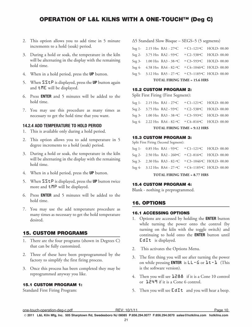
15.1 CUSTOM PROGRAM 1:Standard.First.Firing.Program:
∆5.Standard.Slow.Bisque.–.SEGS–5.(5.segments)
Seg.1-. 2.15.Hrs..RA1.-.27ºC.. º.C1–121ºC... HOLD-.00.00
Seg.2-. 3.75.Hrs..RA2.-.93ºC.. º.C2–538ºC... HOLD-.00.00
Seg.3-... 1.00.Hrs..RA3.-.38-ºC.. º.C3–593ºC.. HOLD-.00.00
Seg.4-... 4.58.Hrs..RA4.-.82-ºC.. º.C4–1046ºC.. HOLD-.00.00
Seg.5-... 3.12.Hrs..RA5.-.27-ºC.. º.C5–1185ºC.. HOLD-.00.00
TOTAL FIRING TIME = 15.6 HRS
15.2 CUSTOM PROGRAM 2:Split.First.Firing.(First.Segment):
Seg.1-. 2.15.Hrs..RA1.-.27ºC.. º.C1–121ºC... HOLD-.00.00
Seg.2-. 3.75.Hrs..RA2.-.93ºC.. º.C2–538ºC... HOLD-.00.00
Seg.3-... 1.00.Hrs..RA3.-.38-ºC.. º.C3–593ºC.. HOLD-.00.00
Seg.4-... 2.22.Hrs..RA4.-.82-ºC.. º.C4–816ºC.. HOLD-.00.00
TOTAL FIRING TIME = 9.12 HRS
15.3 CUSTOM PROGRAM 3:Split.First.Firing.(Second.Segment):
Seg.1-. 0.85.Hrs..RA1.-.93ºC.. º.C1–121ºC... HOLD-.00.00
Seg.2-. 2.50.Hrs..RA2.-.260ºC.. º.C2–816ºC... HOLD-.00.00
Seg.3-... 2.30.Hrs..RA3.-.82-ºC.. º.C3–1046ºC.. HOLD-.00.00
Seg.4-... 3.12.Hrs..RA4.-.27-ºC.. º.C4–1185ºC.. HOLD-.00.00
TOTAL FIRING TIME = 8.77 HRS
15.4 CUSTOM PROGRAM 4:Blank.-.nothing.is.preprogrammed.
16. OPTIONS
16.1 ACCESSING OPTIONS1.. Options.are.accessed.by.holding.the.ENTER.button.
while. turning. the. power. onto. the. control. (by.turning. on. the. kiln. with. the. toggle. switch). and.continuing. to. hold. onto. the. ENTER. button. until..EdIt is.displayed.
2.. .This.activates.the.Options.Menu.
3.. The.first.thing.you.will.see.after.turning.the.power.on.while.pressing.ENTER..is.LL-G.or.1t-1 (This.is.the.software.version).
4.. Then.you.will.see.1288 if.it.is.a.Cone.10.control.or..1249.if.it.is.a.Cone.6.control.
5.. Then.you.will.see.EdIt and.you.will.hear.a.beep..
21
OPERATION OF L&L KILNS WITH A ONE-TOUCH™ (Deg C)
one-touch-operation-deg-c,pdf REV:10/1/11 Page11 2011 L&L Kiln Mfg, Inc. 505 Sharptown Rd, Swedesboro NJ 08085 P:856.294.0077 F:856.294.0070 [email protected] hotkilns.com
You.can.now.let.go.of.the.ENTER button.
16.2 OPTIONS
16.2.1 SOUND: BEEPING ON OR OFF AT END OF PROGRAM1.. The.first.thing.to.change.is.the.action.of.the.beeper.
•. OFF.turns.off.the.beeper..
•. FULL.makes. the.beeper. stay.on.until.any.button.is.pushed...
•. On.makes.the.beeper.sound.15.times.and.then.turn.off.
2.. .If.you.don’t.want.to.change.this.option.then.press.ENTER.
16.2.2 MAXIMUM TEMPERATURE1. On a Cone 6 Version (School-Master): Maximum
Temperature (Deg. C).927,.1093,. and.1249.are.options.
2. On a Cone 10 Version (Liberty-Belle, Doll, Fuego, Robin): Cone. 10. models. have. a. preset.maximum. temperature. limit. of.1288 and. you.will. not. see. the. “Maximum. Temperature”. option.come.up.
16.2.3 TEMPERATURE INDICATION1.. .oF.(Deg.F).or.oC.(Deg.C)..
2.. When.you.are.in.Deg.C,.you.will.always.see.a.little.dot. in. the. display. at. the. bottom. right. to. remind.you..
3.. Use.the.UP or.DOWN button.to.change.the.value.and.then.press.ENTER.
16.2.4 THERMOCOUPLE OFFSET (Deg F)1.. OFFS .(+/-.deg.C)
2.. Display.shows.OFFS..
3.. Press.the.UP.arrow.to.enter.a.positive.offset..
4.. Press.the.DOWN.arrow.to.add.a.negative.sign.to.the.offset,.and.then.the.UP.arrow.to.add.negative.offset.to.the.control..
5.. The. control. comes. with. a. pre-programmed. +8.Deg.C.offset. to.compensate. for. the. thermocouple.
protection.tube..
6.. Note:. if. you. first. press. the. DOWN. button. you. can.only.set.a.negative.value.or.if.you.first.press.the.UP.button.you.can.only.enter.a.positive.value..
7.. You.can.go.back.and.change.this.later.if.you.make.a.mistake.
Note: you can adjust how the kiln fires by adjusting the thermocouple offset. For instance, if your kiln if firing cool (according to a witness cone placed in the kiln) then you can add positive Offset. If it is firing hot then you can reduce the offset or put in a negative offset. Try doing this in 5 degree increments.
17. MESSAGES & DISPLAYSCndL Candle.Time.(this.is.a.low.temperature.firing.used.to.dry.moisture.from.the.clay)
COnE Cone.to.fire.to
COOL Cool.down.rate..OFF (natural.cooling),.SLO (Slow),.MEd (Medium),.FASt.(Fast)
CPLt. Firing.Cycle.Complete.(firing.time.is.alternately.displayed).
dELA. Delay...Displays.when.entering.the.delay.time.(hour:minutes).until.the.start.of.the.firing.
DLy. Delay.. . Alternates. with. the. remaining. delay.time.until.the.start.of.the.kiln.
°F# . Segment.temperature.in.°F–Set.temperature.for.a.user.program..(#.stands.for.numbers.1.through.8)
°C#. Segment.temperature. in.°C.–.Set. temperature.for. a. user. program.. . A. decimal. point. will. display. in.lower.right.corner..(#.stands.for.numbers.1.through.8)
EdIt. Edit.the.default.options.(beeping.at.complete,.temperature. scale,. cone. fire,. delay,. maximum.programmable.temperature)
ErrP. There.has.been. a.power. interruption. that.has.stopped.the.firing...Press.any.button.to.clear.
FASt Fast.(Heat.up.or.Cool.down.rate)
FIrE.. Ready.to.fire.current.program...Press.START.to.begin.firing.
22
OPERATION OF L&L KILNS WITH A ONE-TOUCH™ (Deg C)
one-touch-operation-deg-c,pdf REV:10/1/11 Page12 2011 L&L Kiln Mfg, Inc. 505 Sharptown Rd, Swedesboro NJ 08085 P:856.294.0077 F:856.294.0070 [email protected] hotkilns.com
FULL. Beeps. continuously. at. end. of. firing. until. a.button.is.pressed.
HtUP Heat.up.rates. SLO (Slow),.MEd (Medium),.FASt.(Fast)
HLd Hold.or.Soak.time.at.peak.temperature
HLd#. Soak. time. in. hours:minutes. at. a. hold.temperature..(#.stands.for.numbers.1.through.8)
IdLE This.shows.up.when.the.control.is.not.firing.or.is.not.being.programmed..Message.alternates.with.the.current.kiln.temperature..Similar.to.StOP.
1t-1 This. comes. on. when. you. first. turn. on. the.control.if.it.is.a.Cone.10.control.
LL-G This. comes. on. when. you. first. turn. on. the.control.if.it.is.a.Cone.6.control.
MEd Medium.(Heat.up.or.Cool.down.rate)
OFF. No.beeping.when.firing.is.complete..Or.could.be.that.an.option.is.off.when.setting.options..Also.used.to.show.that.Cooling.is.off.
On. Beeps.for.15.seconds.at.end.of.firing.
rA#. Ramp. Number. (rate. per. hour. of. temperature.increase.or.decrease)..(#.stands.for.numbers.1.through.8)
rStr Restore.default.original.values
SEG. Short. for. Segments.. . You. can. enter. up. to. 8.segments.in.a.program.
SLO Slow.(Heat.up.or.Cool.down.rate)
SStP. Skip.Step.(used.to.advance.to.the.next.ramp)
StOP.The.kiln.is.at.idle.and.ready.to.be.programmed..Message.alternates.with.the.current.kiln.temperature.
CUS1, CUS2, CUS3, CUS4 Custom.program.number.displayed.
18. ERROR CODEStC FAIL... tC. alternating. with. FAIL. indicates.the. thermocouple. has. failed.. . Replace. the. defective.thermocouple...To.clear.the.error,.press.any.button.
Errd. . Displayed. whenever. the. kiln. temperature. is.
38°C.above.the.traveling.set-point,.which.is.the.current.desired.temperature.in.the.kiln..The.traveling.set-point.will. increase.or.decrease.according.to.the.programmed.rate.
Err1. . Displayed. whenever. the. kiln. temperature. is.rising. during. an. up. ramp. slower. than. 9°C/hr.. If. this.rate.continues.for.8.minutes.the.firing.will.be.stopped..Err1.may.be.an.indication.that.the.elements.are.worn.or.that.a.relay.has.stopped.working.
ErrP..Displayed.whenever.there.is.a.power.interruption.that. is. long. enough. to. stop. the. firing.. . If. the. power.interruption.is.brief,.the.kiln.will.continue.to.fire.when.power.is.restored;.in.this.case,.there.will.be.no.indication.of.a.power.failure...To.clear.the.error,.press.any.button.
ErrF. . Displayed. whenever. the. kiln. temperature. is.decreasing. during. a. down. ramp. slower. than. 9°C/hr..If. this. rate. continues. for. 8. minutes. the. firing. will. be.stopped..ErrF. may. be. an. indication. that. a. relay. has.stuck.in.the.on.position.
tC--. The. red. and. yellow. thermocouple. wires. are.reversed.
19. SOFTWARE VERSIONThese.instructions.apply.to.software.version.LL-G.for.the. Cone. 6. version. of. the. control. or.1t-1 for. the.Cone.10.version.of.the.control..You.will.see.this.code.flash.when.you.first.turn.on.the.control.
20. FAHRENHEIT INSTRUCTIONSThese.instructions.are.available.in.a.Fahrenheit.version..Go to hotkilns.com/basic-one-touch-f
21. SPECIFICATIONSGo to hotkilns.com/one-touch-specifications
23
ASSEMBLY INSTRUCTIONS FOR L&L FUEGO AND ROBIN KILNS(ALL VERSIONS)
fuego-robin-assembly.pdf REV:9/14/2010 Page1 2010 L&L Kiln Mfg, Inc. 505 Sharptown Rd, Swedesboro NJ 08085 P:856.294.0077 F:856.294.0070 [email protected] hotkilns.com
TOOLS NEED FOR THE JOBYou will need the following tools for the job:
1) Phillips head screw driver (medium size head)
2) Knife
3) Adjustable Wrench
4) 3/8” Nut Driver or socket wrench
5) Level (not absolutely necessary)
UNPACKING
INSPECT FOR VISIBLE DAMAGEThe carton should arrive without visible damage. If any carton was damaged in transit, you should either refuse shipment or unpack the kiln in the drivers presence in order to file a damage report with the freight company. Call the distributor immediately if there is a problem. SAVE ALL MATERIALS UNTIL YOU ARE SURE YOU WON’T NEED THEM. AT THE VERY LEAST NOTE DAMAGE ON THE BILL- OF-LADING - WITHOUT THIS YOU HAVE NO PROTECTION!
REMOVE TOP FROM CARTON1) Cut the banding around the kiln box.
2) With a screw driver pry off the staples holding the top of the box to the box sleave and remove the top.
UNPACKING THE KILN1) With a screw driver pry off the staples holding the bottom box tray to the box sleave.
2) Next remove the cardboard inset from the carton, and remove the carton sleeve from the skid.
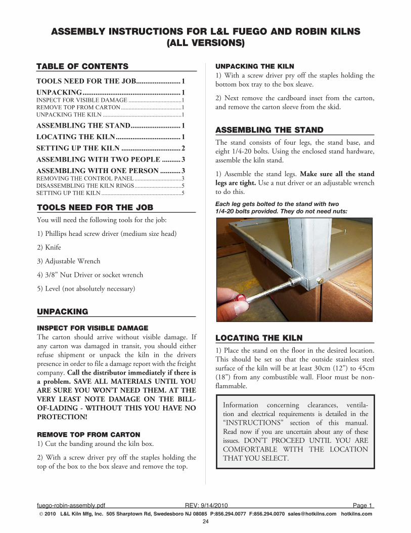
ASSEMBLING THE STANDThe stand consists of four legs, the stand base, and eight 1/4-20 bolts. Using the enclosed stand hardware, assemble the kiln stand.
1) Assemble the stand legs. Make sure all the stand legs are tight. Use a nut driver or an adjustable wrench to do this.
Each leg gets bolted to the stand with two 1/4-20 bolts provided. They do not need nuts:
LOCATING THE KILN1) Place the stand on the floor in the desired location. This should be set so that the outside stainless steel surface of the kiln will be at least 30cm (12”) to 45cm (18”) from any combustible wall. Floor must be non-flammable.
Information concerning clearances, ventila-tion and electrical requirements is detailed in the “INSTRUCTIONS” section of this manual. Read now if you are uncertain about any of these issues. DON’T PROCEED UNTIL YOU ARE COMFORTABLE WITH THE LOCATION THAT YOU SELECT.
TABLE OF CONTENTS
TOOLS NEED FOR THE JOB ........................ 1UNPACKING ..................................................... 1INSPECT FOR VISIBLE DAMAGE ...................................1REMOVE TOP FROM CARTON ........................................1UNPACKING THE KILN ....................................................1
ASSEMBLING THE STAND ........................... 1LOCATING THE KILN ................................... 1SETTING UP THE KILN ................................ 2ASSEMBLING WITH TWO PEOPLE .......... 3ASSEMBLING WITH ONE PERSON ........... 3REMOVING THE CONTROL PANEL ...............................3DISASSEMBLING THE KILN RINGS ...............................5SETTING UP THE KILN .....................................................5
24
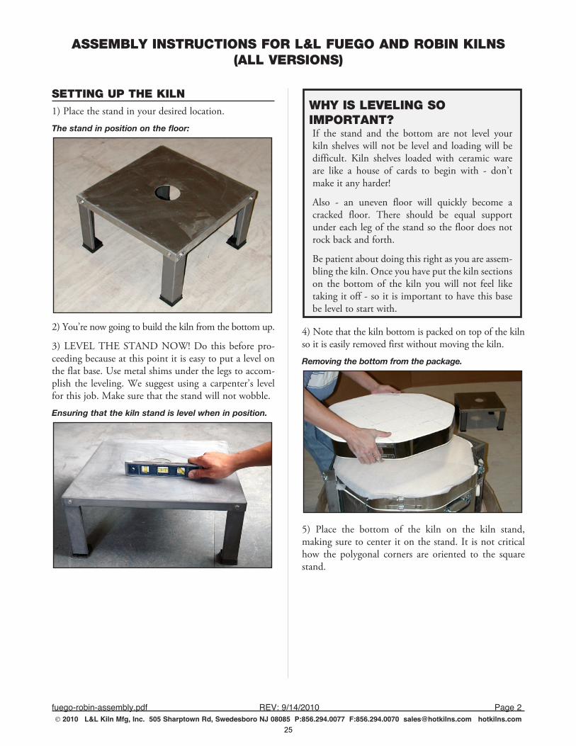
ASSEMBLY INSTRUCTIONS FOR L&L FUEGO AND ROBIN KILNS(ALL VERSIONS)
fuego-robin-assembly.pdf REV:9/14/2010 Page2 2010 L&L Kiln Mfg, Inc. 505 Sharptown Rd, Swedesboro NJ 08085 P:856.294.0077 F:856.294.0070 [email protected] hotkilns.com
SETTING UP THE KILN1) Place the stand in your desired location.
The stand in position on the floor:
2) You’re now going to build the kiln from the bottom up.
3) LEVEL THE STAND NOW! Do this before pro-ceeding because at this point it is easy to put a level on the flat base. Use metal shims under the legs to accom-plish the leveling. We suggest using a carpenter’s level for this job. Make sure that the stand will not wobble.
Ensuring that the kiln stand is level when in position.
WHY IS LEVELING SO IMPORTANT?If the stand and the bottom are not level your kiln shelves will not be level and loading will be difficult. Kiln shelves loaded with ceramic ware are like a house of cards to begin with - don’t make it any harder!
Also - an uneven floor will quickly become a cracked floor. There should be equal support under each leg of the stand so the floor does not rock back and forth.
Be patient about doing this right as you are assem-bling the kiln. Once you have put the kiln sections on the bottom of the kiln you will not feel like taking it off - so it is important to have this base be level to start with.
4) Note that the kiln bottom is packed on top of the kiln so it is easily removed first without moving the kiln.
Removing the bottom from the package.
5) Place the bottom of the kiln on the kiln stand, making sure to center it on the stand. It is not critical how the polygonal corners are oriented to the square stand.
25
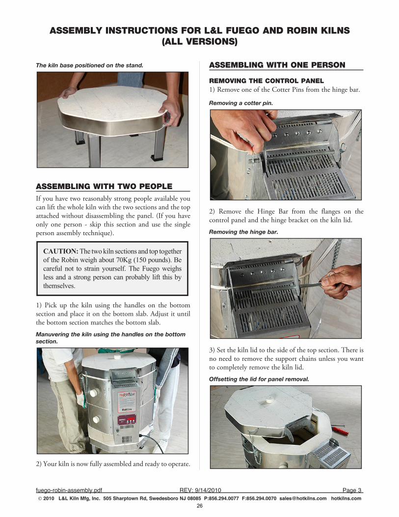
ASSEMBLY INSTRUCTIONS FOR L&L FUEGO AND ROBIN KILNS(ALL VERSIONS)
fuego-robin-assembly.pdf REV:9/14/2010 Page3 2010 L&L Kiln Mfg, Inc. 505 Sharptown Rd, Swedesboro NJ 08085 P:856.294.0077 F:856.294.0070 [email protected] hotkilns.com
The kiln base positioned on the stand.
ASSEMBLING WITH TWO PEOPLEIf you have two reasonably strong people available you can lift the whole kiln with the two sections and the top attached without disassembling the panel. (If you have only one person - skip this section and use the single person assembly technique).
CAUTION: The two kiln sections and top together of the Robin weigh about 70Kg (150 pounds). Be careful not to strain yourself. The Fuego weighs less and a strong person can probably lift this by themselves.
1) Pick up the kiln using the handles on the bottom section and place it on the bottom slab. Adjust it until the bottom section matches the bottom slab.
Manuvering the kiln using the handles on the bottom section.
2) Your kiln is now fully assembled and ready to operate.
ASSEMBLING WITH ONE PERSON
REMOVING THE CONTROL PANEL1) Remove one of the Cotter Pins from the hinge bar.
Removing a cotter pin.
2) Remove the Hinge Bar from the flanges on the control panel and the hinge bracket on the kiln lid.
Removing the hinge bar.
3) Set the kiln lid to the side of the top section. There is no need to remove the support chains unless you want to completely remove the kiln lid.
Offsetting the lid for panel removal.
26
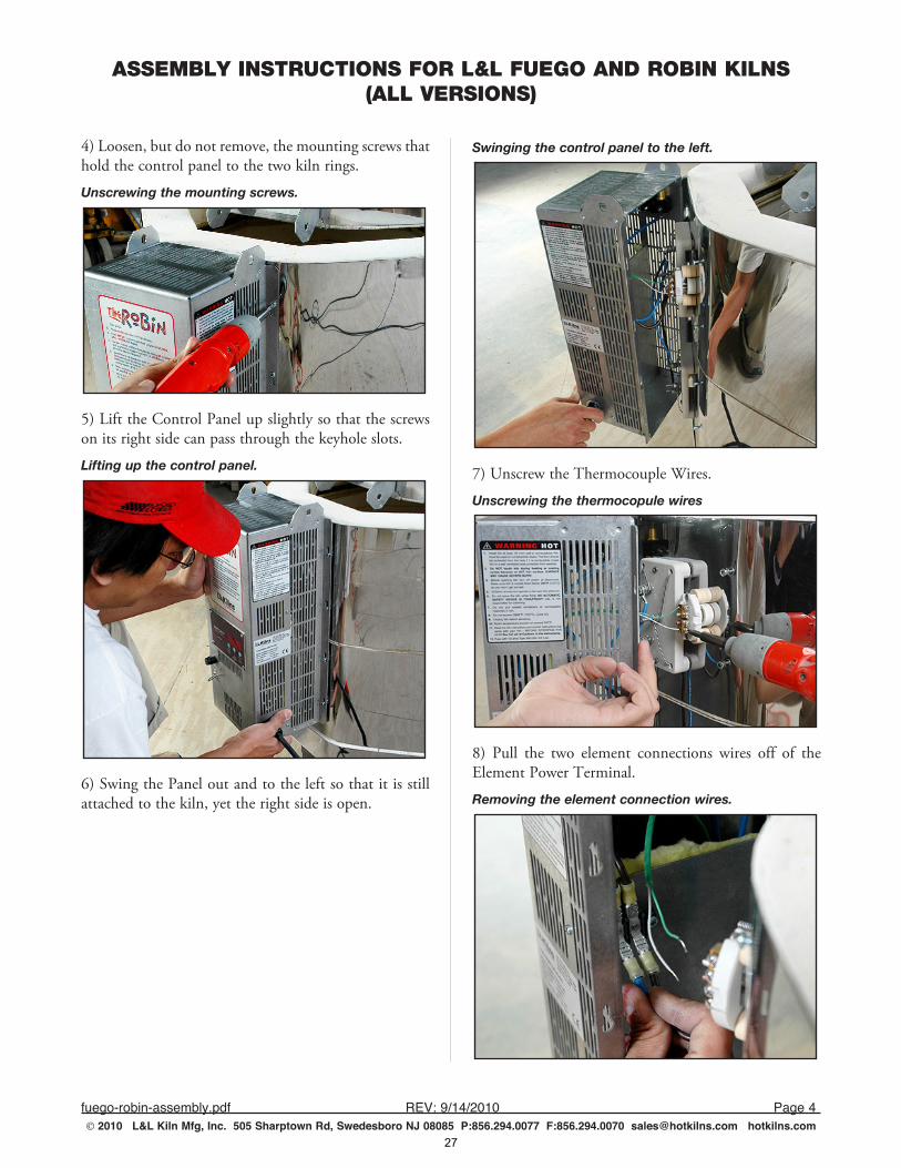
ASSEMBLY INSTRUCTIONS FOR L&L FUEGO AND ROBIN KILNS(ALL VERSIONS)
fuego-robin-assembly.pdf REV:9/14/2010 Page4 2010 L&L Kiln Mfg, Inc. 505 Sharptown Rd, Swedesboro NJ 08085 P:856.294.0077 F:856.294.0070 [email protected] hotkilns.com
4) Loosen, but do not remove, the mounting screws that hold the control panel to the two kiln rings.
Unscrewing the mounting screws.
5) Lift the Control Panel up slightly so that the screws on its right side can pass through the keyhole slots.
Lifting up the control panel.
6) Swing the Panel out and to the left so that it is still attached to the kiln, yet the right side is open.
Swinging the control panel to the left.
7) Unscrew the Thermocouple Wires.
Unscrewing the thermocopule wires
8) Pull the two element connections wires off of the Element Power Terminal.
Removing the element connection wires.
27
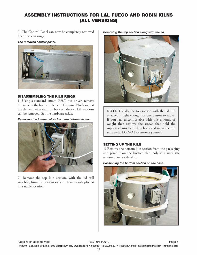
ASSEMBLY INSTRUCTIONS FOR L&L FUEGO AND ROBIN KILNS(ALL VERSIONS)
fuego-robin-assembly.pdf REV:9/14/2010 Page5 2010 L&L Kiln Mfg, Inc. 505 Sharptown Rd, Swedesboro NJ 08085 P:856.294.0077 F:856.294.0070 [email protected] hotkilns.com
9) The Control Panel can now be completely removed from the kiln rings.
The removed control panel.
DISASSEMBLING THE KILN RINGS1) Using a standard 10mm (3/8”) nut driver, remove the nuts on the bottom Element Terminal Block so that the element wires that run between the two kiln sections can be removed. Set the hardware aside.
Removing the jumper wires from the bottom section.
2) Remove the top kiln section, with the lid still attached, from the bottom section. Temporarily place it in a stable location.
Removing the top section along with the lid.
NOTE: Usually the top section with the lid still attached is light enough for one person to move. If you feel uncomfortable with this amount of weight then remove the screws that hold the support chains to the kiln body and move the top separately. Do NOT over-exert yourself.
SETTING UP THE KILN1) Remove the bottom kiln section from the packaging and place it on the bottom slab. Adjust it until the section matches the slab.
Positioning the bottom section on the base.
28
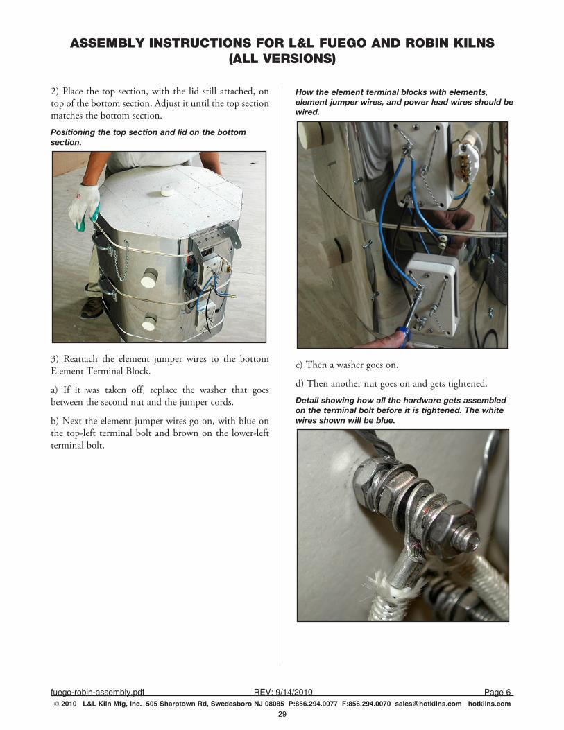
ASSEMBLY INSTRUCTIONS FOR L&L FUEGO AND ROBIN KILNS(ALL VERSIONS)
fuego-robin-assembly.pdf REV:9/14/2010 Page6 2010 L&L Kiln Mfg, Inc. 505 Sharptown Rd, Swedesboro NJ 08085 P:856.294.0077 F:856.294.0070 [email protected] hotkilns.com
2) Place the top section, with the lid still attached, on top of the bottom section. Adjust it until the top section matches the bottom section.
Positioning the top section and lid on the bottom section.
3) Reattach the element jumper wires to the bottom Element Terminal Block.
a) If it was taken off, replace the washer that goes between the second nut and the jumper cords.
b) Next the element jumper wires go on, with blue on the top-left terminal bolt and brown on the lower-left terminal bolt.
How the element terminal blocks with elements, element jumper wires, and power lead wires should be wired.
c) Then a washer goes on.
d) Then another nut goes on and gets tightened.
Detail showing how all the hardware gets assembled on the terminal bolt before it is tightened. The white wires shown will be blue.
29
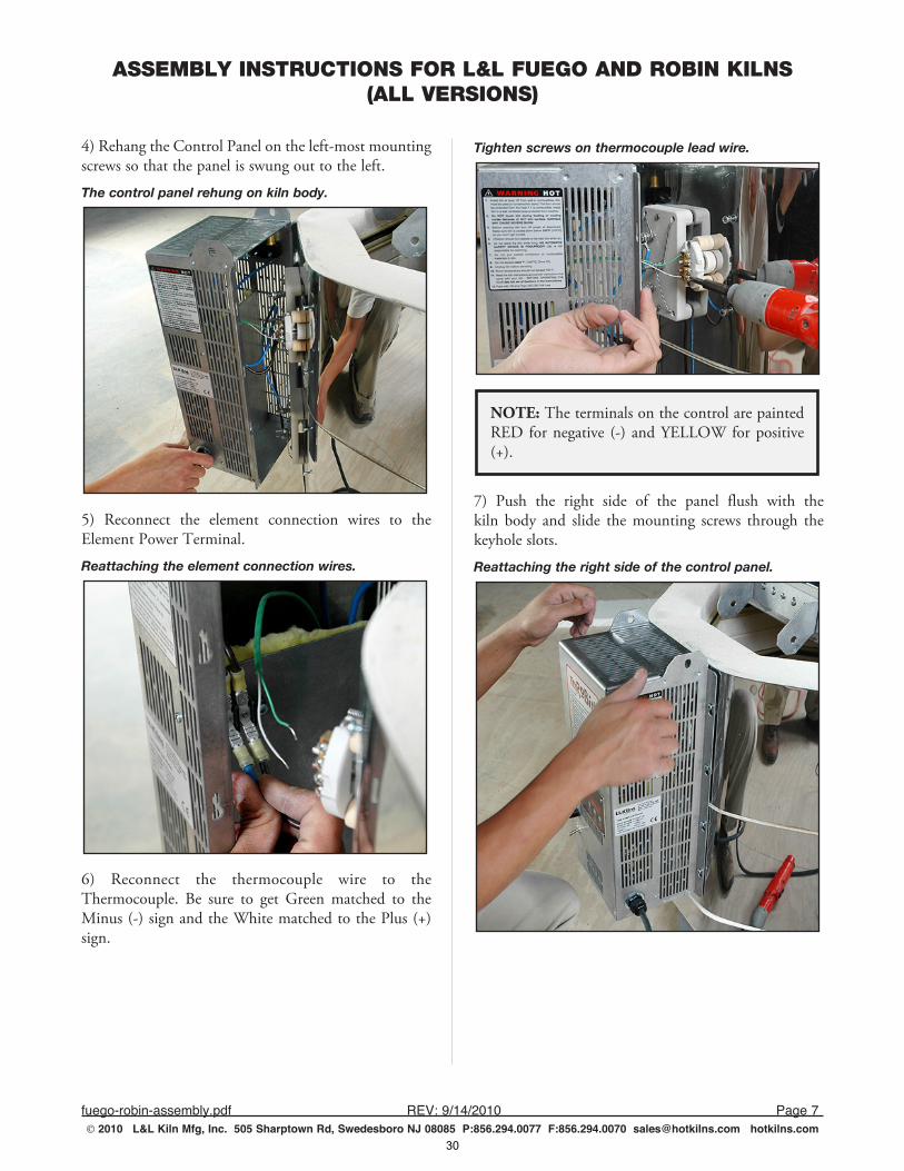
ASSEMBLY INSTRUCTIONS FOR L&L FUEGO AND ROBIN KILNS(ALL VERSIONS)
fuego-robin-assembly.pdf REV:9/14/2010 Page7 2010 L&L Kiln Mfg, Inc. 505 Sharptown Rd, Swedesboro NJ 08085 P:856.294.0077 F:856.294.0070 [email protected] hotkilns.com
4) Rehang the Control Panel on the left-most mounting screws so that the panel is swung out to the left.
The control panel rehung on kiln body.
5) Reconnect the element connection wires to the Element Power Terminal.
Reattaching the element connection wires.
6) Reconnect the thermocouple wire to the Thermocouple. Be sure to get Green matched to the Minus (-) sign and the White matched to the Plus (+) sign.
Tighten screws on thermocouple lead wire.
NOTE: The terminals on the control are painted RED for negative (-) and YELLOW for positive (+).
7) Push the right side of the panel flush with the kiln body and slide the mounting screws through the keyhole slots.
Reattaching the right side of the control panel.
30
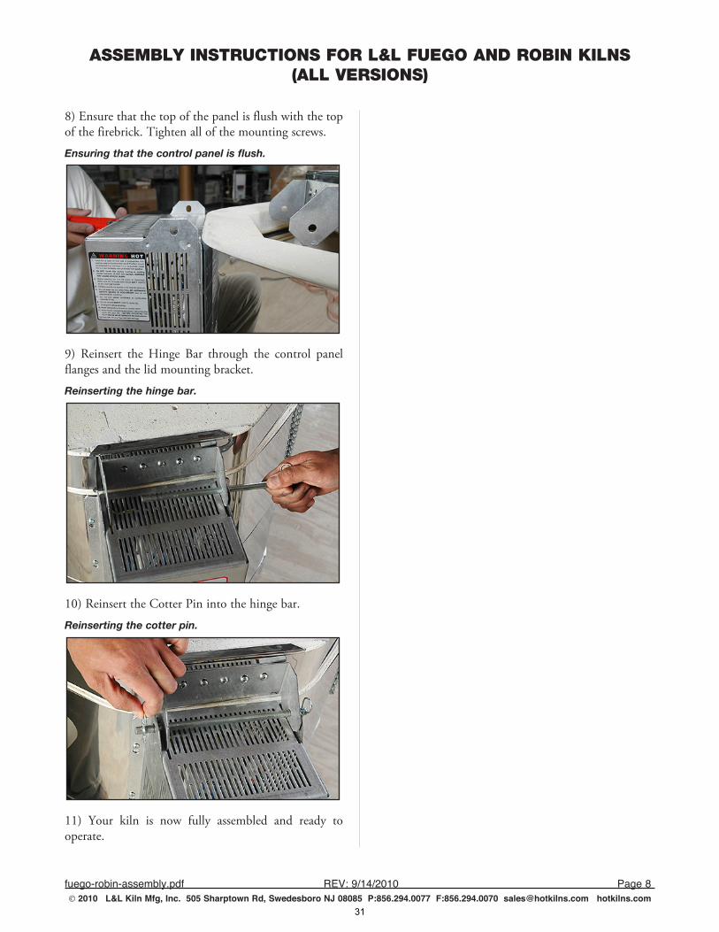
ASSEMBLY INSTRUCTIONS FOR L&L FUEGO AND ROBIN KILNS(ALL VERSIONS)
fuego-robin-assembly.pdf REV:9/14/2010 Page8 2010 L&L Kiln Mfg, Inc. 505 Sharptown Rd, Swedesboro NJ 08085 P:856.294.0077 F:856.294.0070 [email protected] hotkilns.com
8) Ensure that the top of the panel is flush with the top of the firebrick. Tighten all of the mounting screws.
Ensuring that the control panel is flush.
9) Reinsert the Hinge Bar through the control panel flanges and the lid mounting bracket.
Reinserting the hinge bar.
10) Reinsert the Cotter Pin into the hinge bar.
Reinserting the cotter pin.
11) Your kiln is now fully assembled and ready to operate.
31
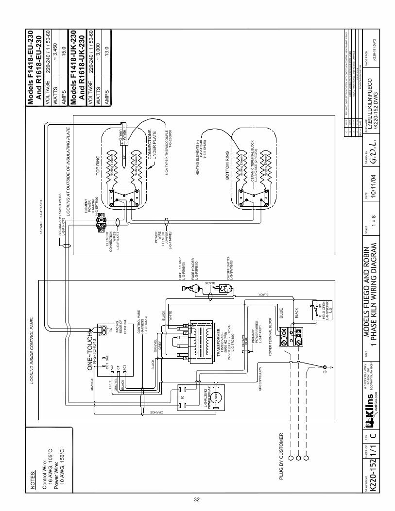
32

PARTS FOR ALL KILNS(ONLINE DATABASE)
online-parts.pdf REV:9/13/2010 Page1 2010 L&L Kiln Mfg, Inc. 505 Sharptown Rd, Swedesboro NJ 08085 P:856.294.0077 F:856.294.0070 [email protected] hotkilns.com
PARTS LIST
A comprehensive and up-to-date listing of parts that pertain to all Kiln Series’ built by L&L Kiln Mfg., Inc. can now be found on our website at,http://hotkilns.com/parts
Use the “Kiln Series” Parts Filter to narrow down the list of available parts to those that pertain to your specific kiln.
If further brevity is desired, use the “Category” Parts Filter as well.
33
TROUBLESHOOTING AND REPAIR INSTRUCTIONS FOR L&L FUEGO AND ROBIN KILNS (UNITED KINGDOM VERSION)
fuego-robin-troubleshoot-uk.pdf REV:9/21/2010 Page1 2010 L&L Kiln Mfg, Inc. 505 Sharptown Rd, Swedesboro NJ 08085 P:856.294.0077 F:856.294.0070 [email protected] hotkilns.com
TABLE OF CONTENTS
AN EASY-TO-USE TROUBLESHOOTING GUIDE ........................................................................3LIVE TESTS ..............................................................3CONTROL DISPLAY DOESN’T SHOW ANYTHING................................................................4ON/OFF SWITCH .................................................................4FUSE ......................................................................................4PLUG & CORD .....................................................................4CIRCUIT BREAKER / POWER SOURCE ..........................4INTERNAL WIRING ............................................................5SHORT CIRCUITS ...............................................................5CONTROL TRANSFORMER ..............................................5CONTROL BOARD ..............................................................6
DISPLAY READS FAIL and tC ..............................6DISPLAY IS NORMAL BUT KILN WON’T HEAT UP .....................................................6PROGRAMMING .................................................................6WIRING .................................................................................6CONTROL BOARD OUTPUTS ..........................................7BAD POWER RELAY ..........................................................7BAD ELEMENTS .................................................................7
KILN FIRES UNEVENLY .......................................7PEEPHOLES .........................................................................7LID SEAL ..............................................................................7ELEMENTS ...........................................................................7LOADING .............................................................................8FIRING WITH CONES ........................................................8
KILN FIRES TOO HOT OR COLD .......................8FIRING WITH CONES ........................................................8HOLD TIMES .......................................................................8THERMOCOUPLE DRIFT ..................................................8
KILN STALLS ...........................................................8KILN FIRES SLOWLY ............................................8BAD OR WRONG VOLTAGE ............................................8ELEMENT AGING ...............................................................9POWER RELAYS .................................................................9BAD WIRING .......................................................................9WIRING IN THE KILN ........................................................10ELEMENT CONNECTIONS ................................................10HEAT LEAKAGE & VENTS ...............................................11ADDING MORE INSULATION ..........................................11
KILN HEATS TOO FAST .......................................11VOLTAGE .............................................................................11ELEMENTS ...........................................................................11
ERROR MESSAGES ................................................11Errd ........................................................................................11Err1 ........................................................................................11ErrP ........................................................................................12ErrF ........................................................................................12tC- .........................................................................................12
FAIL .......................................................................................12CAN YOU RESTART THE KILN AFTER IT STOPS BECAUSE OF ERROR CODES? .........................................12WORST CASE SCENARIO FOR RESTARTINGAFTER AN ERROR CODE ..................................................12
REMOVING PANEL FOR SERVICE ..................13
REPLACING ONE-TOUCH™ ............................ 13REPLACING TRANSFORMER .............................13REPLACING POWER RELAY ..............................14REPLACING FUSE HOLDER ................................14REPLACING THERMOCOUPLES ......................14REPLACING ELEMENTS ......................................15REPLACING ELEMENT HOLDERS ....................17METHOD #1 .........................................................................17METHOD #2 .........................................................................18
CRACKS IN THE LID & BOTTOM ......................19TIGHTENING STAINLESS BANDS ......................19REPLACING FIREBRICK IN SIDES ....................19DRILLING OUT HOLES FOR PEEPHOLES ......20DRILLING OUT FOR ELEMENT CONNECTIONS ........................................................20REPLACING BOTTOMS ........................................20REPLACING LIDS ...................................................20CHECKING ELEMENT OHMS .............................21
34
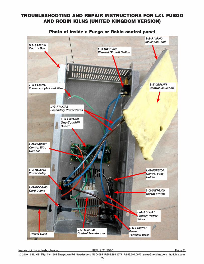
TROUBLESHOOTING AND REPAIR INSTRUCTIONS FOR L&L FUEGO AND ROBIN KILNS (UNITED KINGDOM VERSION)
fuego-robin-troubleshoot-uk.pdf REV:9/21/2010 Page2 2010 L&L Kiln Mfg, Inc. 505 Sharptown Rd, Swedesboro NJ 08085 P:856.294.0077 F:856.294.0070 [email protected] hotkilns.com
Power Cord
L-G-PCCP/00 Cord Clamp
L-G-F14X/P1 Primary Power Wires
L-G-RL25/12 Power Relay
L-G-TR24/00 Control Transformer
L-G-P301/00 One-Touch™ Board
L-G-SWTG/00 On/Off switch
L-G-FSPB/00 Control Fuse Holder
S-E-F14X/00 Control Box
L-G-F14X/CT Control Wire Harness
Photo of inside a Fuego or Robin control panel
L-G-PB2P/EF Power Terminal Block
L-G-F14X/P2 Secondary Power Wires
T-G-F14X/HT Thermocouple Lead Wire
L-G-SWCF/00 Element Shutoff Switch
S-E-LBPL/IN Control Insulation
S-E-F14P/00 Insulation Plate
35
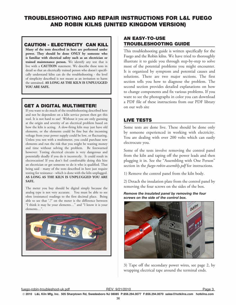
TROUBLESHOOTING AND REPAIR INSTRUCTIONS FOR L&L FUEGO AND ROBIN KILNS (UNITED KINGDOM VERSION)
fuego-robin-troubleshoot-uk.pdf REV:9/21/2010 Page3 2010 L&L Kiln Mfg, Inc. 505 Sharptown Rd, Swedesboro NJ 08085 P:856.294.0077 F:856.294.0070 [email protected] hotkilns.com
CAUTION - ELECTRICITY CAN KILLMany of the tests described in here are performed under power. They should be done ONLY by someone who is familiar with electrical safety such as an electrician or trained maintenance person. We identify any test that is live with a CAUTION statement. We describe these tests in detail so that an electrically trained person who doesn’t specifi-cally understand kilns can do the troubleshooting - the level of simplicity described is not meant as an invitation to harm the untrained. AS LONG AS THE KILN IS UNPLUGGED YOU ARE SAFE.
AN EASY-TO-USE TROUBLESHOOTING GUIDEThis troubleshooting guide is written specifically for the Fuego and the Robin kilns. We have tried to thoroughly illustrate it to guide you through step-by-step to solve most of the potential problems you might encounter. It is organized by symptom and potential causes and solutions. There are two major sections. The first section tells you how to diagnose the problem. The second section provides detailed explanations on how to change components and fix various problems. If you want to see the photographs in color you can download a PDF file of these instructions from our PDF library on our web site
LIVE TESTSSome tests are done live. These should be done only by someone experienced in working with electricity. You are dealing with over 200 volts which can easily electrocute you.
Some of the tests involve removing the control panel from the kiln and taping off the power leads and then plugging it in. See the “Assembling with One Person” section in the fuego-robin-assembly.pdf for instructions.
1) Remove the control panel from the kiln body.
2) Detach the insulation plate from the control panel by removing the four screws on the sides of the box.
Remove the insulated panel by removing the four screws on the side of the control box.
3) Tape off the secondary power wires, see page 2, by wrapping electrical tape around the terminal ends.
GET A DIGITAL MULTIMETER!If you want to do much of the troubleshooting described here and not be dependent on a kiln service person then get this tool. It is not hard to use! Without it you are only guessing at the origin and severity of an electrical problem based on how the kiln is acting. A slow-firing kiln may just have old elements, or the elements could be fine but the incoming voltage from your power supply could be low, or fluctuating. Unless you test with a multimeter, you could purchase new elements and run the risk that you might be wasting money and time without solving the problem. Be forewarned however: Testing electrical circuits is very dangerous and potentially deadly if you do it incorrectly. It could result in electrocution! If you don’t feel comfortable doing this hire an electrician or get someone to do it who is qualified. That being said - many of the tests described in here just require testing for resistance - which is done with the kiln unplugged. AS LONG AS THE KILN IS UNPLUGGED YOU ARE SAFE.
The meter you buy should be digital simply because the analog type is not very accurate. You must be able to see ohm (resistance) readings to the first decimal place. Being able to see that ‘.7’ on the meter is the difference between “I think it may be your elements…” and “I know it is your elements…”.
36
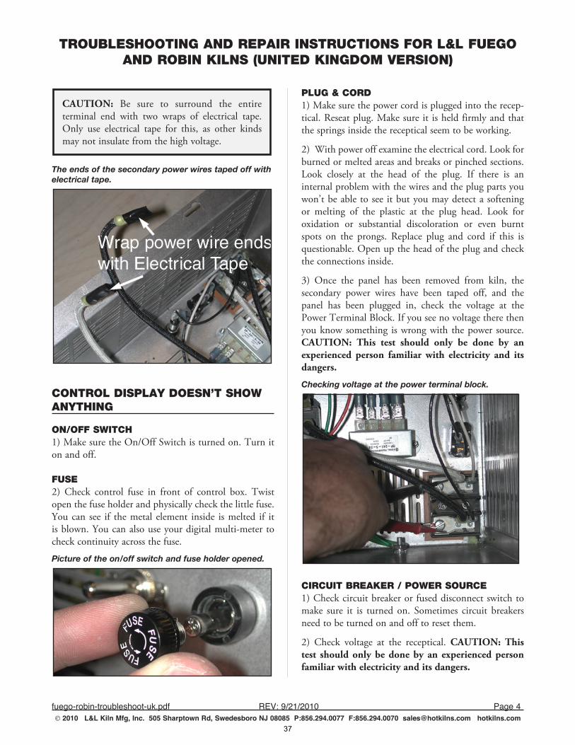
TROUBLESHOOTING AND REPAIR INSTRUCTIONS FOR L&L FUEGO AND ROBIN KILNS (UNITED KINGDOM VERSION)
fuego-robin-troubleshoot-uk.pdf REV:9/21/2010 Page4 2010 L&L Kiln Mfg, Inc. 505 Sharptown Rd, Swedesboro NJ 08085 P:856.294.0077 F:856.294.0070 [email protected] hotkilns.com
CAUTION: Be sure to surround the entire terminal end with two wraps of electrical tape. Only use electrical tape for this, as other kinds may not insulate from the high voltage.
The ends of the secondary power wires taped off with electrical tape.
CONTROL DISPLAY DOESN’T SHOW ANYTHING
ON/OFF SWITCH1) Make sure the On/Off Switch is turned on. Turn it on and off.
FUSE2) Check control fuse in front of control box. Twist open the fuse holder and physically check the little fuse. You can see if the metal element inside is melted if it is blown. You can also use your digital multi-meter to check continuity across the fuse.
Picture of the on/off switch and fuse holder opened.
PLUG & CORD1) Make sure the power cord is plugged into the recep-tical. Reseat plug. Make sure it is held firmly and that the springs inside the receptical seem to be working.
2) With power off examine the electrical cord. Look for burned or melted areas and breaks or pinched sections. Look closely at the head of the plug. If there is an internal problem with the wires and the plug parts you won’t be able to see it but you may detect a softening or melting of the plastic at the plug head. Look for oxidation or substantial discoloration or even burnt spots on the prongs. Replace plug and cord if this is questionable. Open up the head of the plug and check the connections inside.
3) Once the panel has been removed from kiln, the secondary power wires have been taped off, and the panel has been plugged in, check the voltage at the Power Terminal Block. If you see no voltage there then you know something is wrong with the power source. CAUTION: This test should only be done by an experienced person familiar with electricity and its dangers.
Checking voltage at the power terminal block.
CIRCUIT BREAKER / POWER SOURCE1) Check circuit breaker or fused disconnect switch to make sure it is turned on. Sometimes circuit breakers need to be turned on and off to reset them.
2) Check voltage at the receptical. CAUTION: This test should only be done by an experienced person familiar with electricity and its dangers.
37
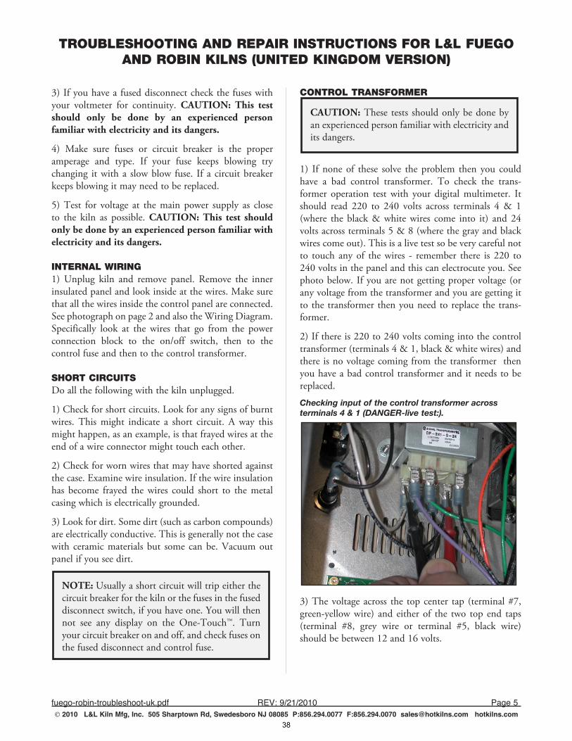
TROUBLESHOOTING AND REPAIR INSTRUCTIONS FOR L&L FUEGO AND ROBIN KILNS (UNITED KINGDOM VERSION)
fuego-robin-troubleshoot-uk.pdf REV:9/21/2010 Page5 2010 L&L Kiln Mfg, Inc. 505 Sharptown Rd, Swedesboro NJ 08085 P:856.294.0077 F:856.294.0070 [email protected] hotkilns.com
3) If you have a fused disconnect check the fuses with your voltmeter for continuity. CAUTION: This test should only be done by an experienced person familiar with electricity and its dangers.
4) Make sure fuses or circuit breaker is the proper amperage and type. If your fuse keeps blowing try changing it with a slow blow fuse. If a circuit breaker keeps blowing it may need to be replaced.
5) Test for voltage at the main power supply as close to the kiln as possible. CAUTION: This test should only be done by an experienced person familiar with electricity and its dangers.
INTERNAL WIRING1) Unplug kiln and remove panel. Remove the inner insulated panel and look inside at the wires. Make sure that all the wires inside the control panel are connected. See photograph on page 2 and also the Wiring Diagram. Specifically look at the wires that go from the power connection block to the on/off switch, then to the control fuse and then to the control transformer.
SHORT CIRCUITSDo all the following with the kiln unplugged.
1) Check for short circuits. Look for any signs of burnt wires. This might indicate a short circuit. A way this might happen, as an example, is that frayed wires at the end of a wire connector might touch each other.
2) Check for worn wires that may have shorted against the case. Examine wire insulation. If the wire insulation has become frayed the wires could short to the metal casing which is electrically grounded.
3) Look for dirt. Some dirt (such as carbon compounds) are electrically conductive. This is generally not the case with ceramic materials but some can be. Vacuum out panel if you see dirt.
NOTE: Usually a short circuit will trip either the circuit breaker for the kiln or the fuses in the fused disconnect switch, if you have one. You will then not see any display on the One-Touch™. Turn your circuit breaker on and off, and check fuses on the fused disconnect and control fuse.
CONTROL TRANSFORMER
CAUTION: These tests should only be done by an experienced person familiar with electricity and its dangers.
1) If none of these solve the problem then you could have a bad control transformer. To check the trans-former operation test with your digital multimeter. It should read 220 to 240 volts across terminals 4 & 1 (where the black & white wires come into it) and 24 volts across terminals 5 & 8 (where the gray and black wires come out). This is a live test so be very careful not to touch any of the wires - remember there is 220 to 240 volts in the panel and this can electrocute you. See photo below. If you are not getting proper voltage (or any voltage from the transformer and you are getting it to the transformer then you need to replace the trans-former.
2) If there is 220 to 240 volts coming into the control transformer (terminals 4 & 1, black & white wires) and there is no voltage coming from the transformer then you have a bad control transformer and it needs to be replaced.
Checking input of the control transformer across terminals 4 & 1 (DANGER-live test:).
3) The voltage across the top center tap (terminal #7, green-yellow wire) and either of the two top end taps (terminal #8, grey wire or terminal #5, black wire) should be between 12 and 16 volts.
38
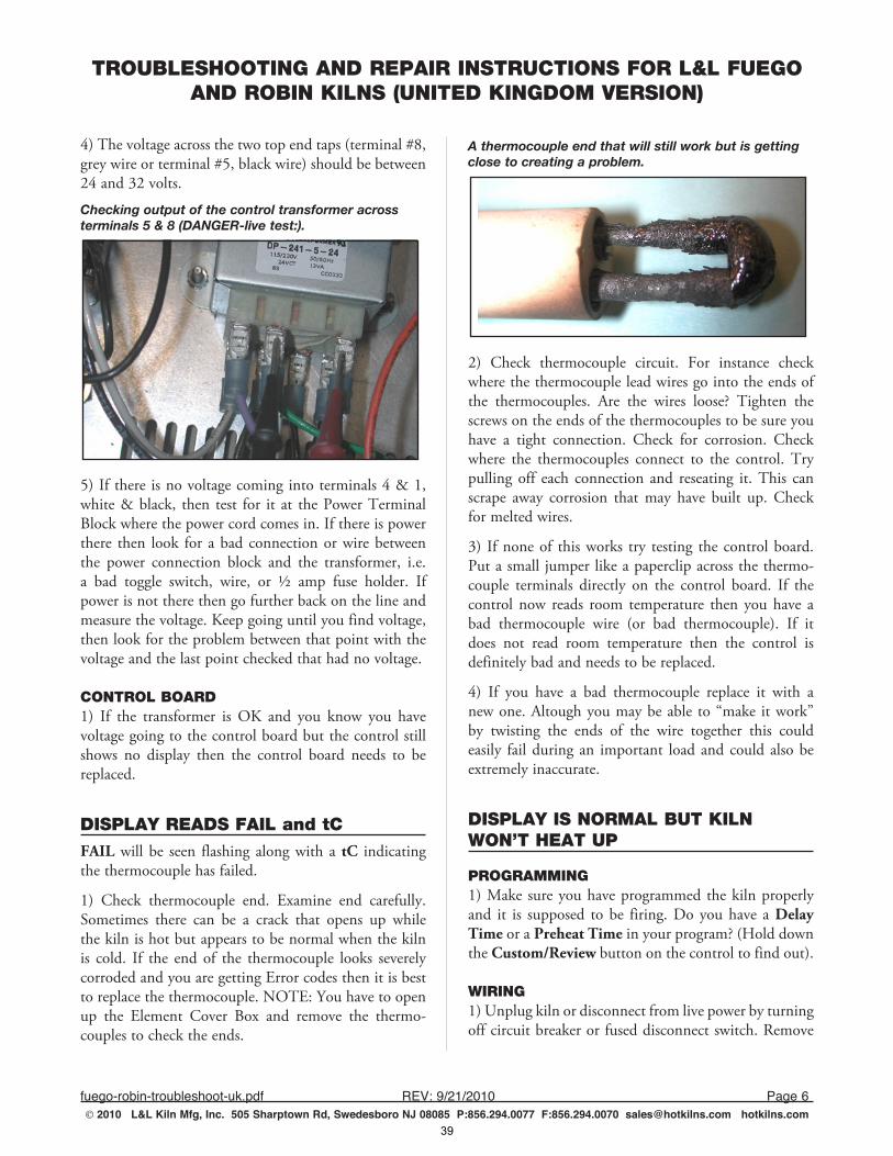
TROUBLESHOOTING AND REPAIR INSTRUCTIONS FOR L&L FUEGO AND ROBIN KILNS (UNITED KINGDOM VERSION)
fuego-robin-troubleshoot-uk.pdf REV:9/21/2010 Page6 2010 L&L Kiln Mfg, Inc. 505 Sharptown Rd, Swedesboro NJ 08085 P:856.294.0077 F:856.294.0070 [email protected] hotkilns.com
4) The voltage across the two top end taps (terminal #8, grey wire or terminal #5, black wire) should be between 24 and 32 volts.
Checking output of the control transformer across terminals 5 & 8 (DANGER-live test:).
5) If there is no voltage coming into terminals 4 & 1, white & black, then test for it at the Power Terminal Block where the power cord comes in. If there is power there then look for a bad connection or wire between the power connection block and the transformer, i.e. a bad toggle switch, wire, or ½ amp fuse holder. If power is not there then go further back on the line and measure the voltage. Keep going until you find voltage, then look for the problem between that point with the voltage and the last point checked that had no voltage.
CONTROL BOARD1) If the transformer is OK and you know you have voltage going to the control board but the control still shows no display then the control board needs to be replaced.
DISPLAY READS FAIL and tCFAIL will be seen flashing along with a tC indicating the thermocouple has failed.
1) Check thermocouple end. Examine end carefully. Sometimes there can be a crack that opens up while the kiln is hot but appears to be normal when the kiln is cold. If the end of the thermocouple looks severely corroded and you are getting Error codes then it is best to replace the thermocouple. NOTE: You have to open up the Element Cover Box and remove the thermo-couples to check the ends.
A thermocouple end that will still work but is getting close to creating a problem.
2) Check thermocouple circuit. For instance check where the thermocouple lead wires go into the ends of the thermocouples. Are the wires loose? Tighten the screws on the ends of the thermocouples to be sure you have a tight connection. Check for corrosion. Check where the thermocouples connect to the control. Try pulling off each connection and reseating it. This can scrape away corrosion that may have built up. Check for melted wires.
3) If none of this works try testing the control board. Put a small jumper like a paperclip across the thermo-couple terminals directly on the control board. If the control now reads room temperature then you have a bad thermocouple wire (or bad thermocouple). If it does not read room temperature then the control is definitely bad and needs to be replaced.
4) If you have a bad thermocouple replace it with a new one. Altough you may be able to “make it work” by twisting the ends of the wire together this could easily fail during an important load and could also be extremely inaccurate.
DISPLAY IS NORMAL BUT KILN WON’T HEAT UP
PROGRAMMING1) Make sure you have programmed the kiln properly and it is supposed to be firing. Do you have a Delay Time or a Preheat Time in your program? (Hold down the Custom/Review button on the control to find out).
WIRING1) Unplug kiln or disconnect from live power by turning off circuit breaker or fused disconnect switch. Remove
39
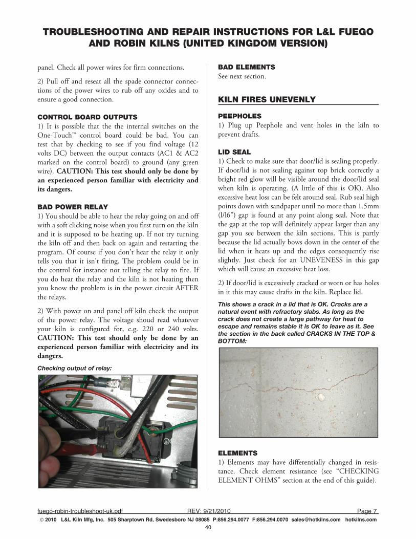
TROUBLESHOOTING AND REPAIR INSTRUCTIONS FOR L&L FUEGO AND ROBIN KILNS (UNITED KINGDOM VERSION)
fuego-robin-troubleshoot-uk.pdf REV:9/21/2010 Page7 2010 L&L Kiln Mfg, Inc. 505 Sharptown Rd, Swedesboro NJ 08085 P:856.294.0077 F:856.294.0070 [email protected] hotkilns.com
panel. Check all power wires for firm connections.
2) Pull off and reseat all the spade connector connec-tions of the power wires to rub off any oxides and to ensure a good connection.
CONTROL BOARD OUTPUTS1) It is possible that the the internal switches on the One-Touch™ control board could be bad. You can test that by checking to see if you find voltage (12 volts DC) between the output contacts (AC1 & AC2 marked on the control board) to ground (any green wire). CAUTION: This test should only be done by an experienced person familiar with electricity and its dangers.
BAD POWER RELAY1) You should be able to hear the relay going on and off with a soft clicking noise when you first turn on the kiln and it is supposed to be heating up. If not try turning the kiln off and then back on again and restarting the program. Of course if you don’t hear the relay it only tells you that it isn’t firing. The problem could be in the control for instance not telling the relay to fire. If you do hear the relay and the kiln is not heating then you know the problem is in the power circuit AFTER the relays.
2) With power on and panel off kiln check the output of the power relay. The voltage shoud read whatever your kiln is configured for, e.g. 220 or 240 volts. CAUTION: This test should only be done by an experienced person familiar with electricity and its dangers.
Checking output of relay:
BAD ELEMENTSSee next section.
KILN FIRES UNEVENLY
PEEPHOLES1) Plug up Peephole and vent holes in the kiln to prevent drafts.
LID SEAL1) Check to make sure that door/lid is sealing properly. If door/lid is not sealing against top brick correctly a bright red glow will be visible around the door/lid seal when kiln is operating. (A little of this is OK). Also excessive heat loss can be felt around seal. Rub seal high points down with sandpaper until no more than 1.5mm (l/l6”) gap is found at any point along seal. Note that the gap at the top will definitely appear larger than any gap you see between the kiln sections. This is partly because the lid actually bows down in the center of the lid when it heats up and the edges consequently rise slightly. Just check for an UNEVENESS in this gap which will cause an excessive heat loss.
2) If door/lid is excessively cracked or worn or has holes in it this may cause drafts in the kiln. Replace lid.
This shows a crack in a lid that is OK. Cracks are a natural event with refractory slabs. As long as the crack does not create a large pathway for heat to escape and remains stable it is OK to leave as it. See the section in the back called CRACKS IN THE TOP & BOTTOM:
ELEMENTS1) Elements may have differentially changed in resis-tance. Check element resistance (see “CHECKING ELEMENT OHMS” section at the end of this guide).
40
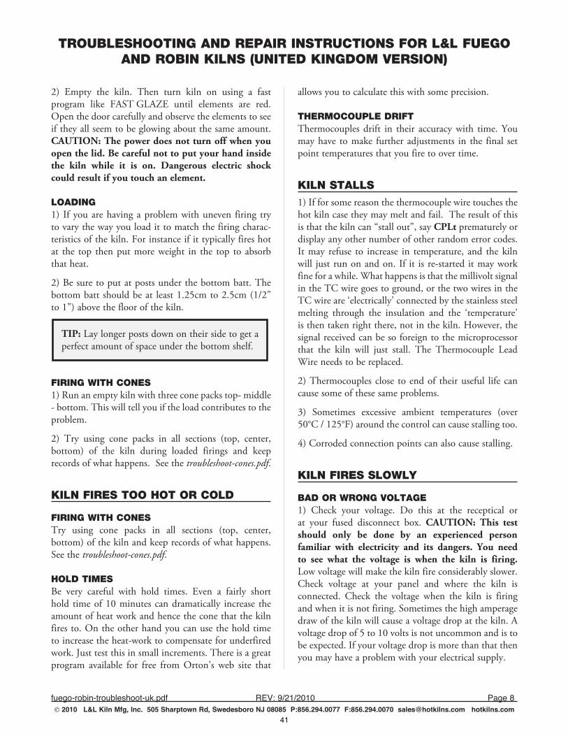
TROUBLESHOOTING AND REPAIR INSTRUCTIONS FOR L&L FUEGO AND ROBIN KILNS (UNITED KINGDOM VERSION)
fuego-robin-troubleshoot-uk.pdf REV:9/21/2010 Page8 2010 L&L Kiln Mfg, Inc. 505 Sharptown Rd, Swedesboro NJ 08085 P:856.294.0077 F:856.294.0070 [email protected] hotkilns.com
2) Empty the kiln. Then turn kiln on using a fast program like FAST GLAZE until elements are red. Open the door carefully and observe the elements to see if they all seem to be glowing about the same amount. CAUTION: The power does not turn off when you open the lid. Be careful not to put your hand inside the kiln while it is on. Dangerous electric shock could result if you touch an element.
LOADING1) If you are having a problem with uneven firing try to vary the way you load it to match the firing charac-teristics of the kiln. For instance if it typically fires hot at the top then put more weight in the top to absorb that heat.
2) Be sure to put at posts under the bottom batt. The bottom batt should be at least 1.25cm to 2.5cm (1/2” to 1”) above the floor of the kiln.
TIP: Lay longer posts down on their side to get a perfect amount of space under the bottom shelf.
FIRING WITH CONES1) Run an empty kiln with three cone packs top- middle - bottom. This will tell you if the load contributes to the problem.
2) Try using cone packs in all sections (top, center, bottom) of the kiln during loaded firings and keep records of what happens. See the troubleshoot-cones.pdf.
KILN FIRES TOO HOT OR COLD
FIRING WITH CONESTry using cone packs in all sections (top, center, bottom) of the kiln and keep records of what happens. See the troubleshoot-cones.pdf.
HOLD TIMESBe very careful with hold times. Even a fairly short hold time of 10 minutes can dramatically increase the amount of heat work and hence the cone that the kiln fires to. On the other hand you can use the hold time to increase the heat-work to compensate for underfired work. Just test this in small increments. There is a great program available for free from Orton’s web site that
allows you to calculate this with some precision.
THERMOCOUPLE DRIFTThermocouples drift in their accuracy with time. You may have to make further adjustments in the final set point temperatures that you fire to over time.
KILN STALLS1) If for some reason the thermocouple wire touches the hot kiln case they may melt and fail. The result of this is that the kiln can “stall out”, say CPLt prematurely or display any other number of other random error codes. It may refuse to increase in temperature, and the kiln will just run on and on. If it is re-started it may work fine for a while. What happens is that the millivolt signal in the TC wire goes to ground, or the two wires in the TC wire are ‘electrically’ connected by the stainless steel melting through the insulation and the ‘temperature’ is then taken right there, not in the kiln. However, the signal received can be so foreign to the microprocessor that the kiln will just stall. The Thermocouple Lead Wire needs to be replaced.
2) Thermocouples close to end of their useful life can cause some of these same problems.
3) Sometimes excessive ambient temperatures (over 50°C / 125°F) around the control can cause stalling too.
4) Corroded connection points can also cause stalling.
KILN FIRES SLOWLY
BAD OR WRONG VOLTAGE1) Check your voltage. Do this at the receptical or at your fused disconnect box. CAUTION: This test should only be done by an experienced person familiar with electricity and its dangers. You need to see what the voltage is when the kiln is firing. Low voltage will make the kiln fire considerably slower. Check voltage at your panel and where the kiln is connected. Check the voltage when the kiln is firing and when it is not firing. Sometimes the high amperage draw of the kiln will cause a voltage drop at the kiln. A voltage drop of 5 to 10 volts is not uncommon and is to be expected. If your voltage drop is more than that then you may have a problem with your electrical supply.
41
TROUBLESHOOTING AND REPAIR INSTRUCTIONS FOR L&L FUEGO AND ROBIN KILNS (UNITED KINGDOM VERSION)
fuego-robin-troubleshoot-uk.pdf REV:9/21/2010 Page9 2010 L&L Kiln Mfg, Inc. 505 Sharptown Rd, Swedesboro NJ 08085 P:856.294.0077 F:856.294.0070 [email protected] hotkilns.com
2) Make sure no other large electrical appliances such as a clothes dryer or electric oven are on when you are operating your kiln. This may cause a voltage drop which would slow the kiln down.
3) Voltage may vary in your area depending on season and time of day. Frequently there are “brown outs” during the summer months in some areas. This is when the electric utility reduces the voltage. Try firing at night after peak electrical use hours. You can use your Delay feature to do this easily. Find out from your local utility company when the end of the peak period of electrical use is. Some utilities offer preferential rates for using electricity at night because it is cheaper for them.
4) Check to see what the wire size of your circuit is. If it is very long (more than 50 feet) from your main circuit box then the wire size might need to be higher (#8 instead of #10 wire).
ELEMENT AGING1) Elements age when fired and the elements increase in resistance. When they increase in resistance the amount of power they develop decreases. See the section on “CHECKING ELEMENT RESISTANCE” at end of this guide.
2) Replacing only one element may cause an unbalance in firing.
3) Empty the kiln. Then turn kiln on until elements are red. Open the door carefully and observe the elements to see if they all seem to be glowing about the same amount.
4) Elements expand and grow with age. If you fire low-fire clay and glazes and never get above cone 05 or so, your elements will last a long time, especially if you are only bisque firing. This is good, to a point. If you only low-fire, the problem you are most likely to encounter over many years is that the elements will expand as they age. The length and the coil diameter increase. Meanwhile the atmosphere in the kiln slowly eats away at the metal of the element. Although the total resistance usually increases as the elements age, sometimes it decreases, or reverses itself. This usually only happens when the elements are very old but have not yet failed completely. As the element expands, it binds up in the corners. This can make the individual coils push together and touch each other in the corners,
making a short cut for the electricity, reducing the amount of element material the electricity must pass through, and therefore reducing the resistance in the whole element. This may make it hotter in the kiln, but if there is a lot of element material jammed in the corners there will not be enough material left in the coiled form to radiate the heat generated by the increased amperage and decreased resistance. Only the parts of the wire not touching the coils on either side of them will emit heat. More amperage through the electrical components in the control could cause damage if the situation continues or the resistance drops far enough. In addition, the expanding diameter of an element can make it difficult to get it out of the holder. Usually this will not happen to those firing to higher temperatures because the maximum temperature of the kiln is quickly compromised by increases in the resis-tance, requiring the elements to be changed long before they can jam up in the corners. Also, high temperatures and glaze firings are more prone to eating through the element, causing it to fail, before the element can expand enough to cause the problems mentioned above. Visually inspect your elements for the above conditions and do a resistance check. If you see this it may be time to change elements.
POWER RELAYS1) Power Relays may cause poor transfer of power to elements when they have been used for a long period of time. It is not always a total failure - which is of course harder to troubleshoot. If this is suspected replace the relay.
BAD WIRING1) Have an electrician check your wiring. We have seen aluminum wire cause intermittent problems with allowing enough voltage through. We do not recommend aluminum wiring. The problem with it is that aluminum oxide, which is formed from heat, is a resistor while copper oxide is not a resistor. With kilns you will often develop some heat in the electrical lines. If all connections are perfect and the wire is oversized you probably will not have a problem - but why take that chance? Make sure your wires are of the proper size and that all connections are good.
42
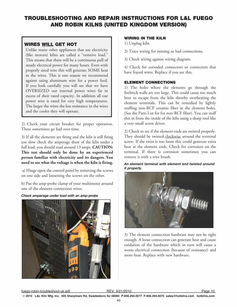
TROUBLESHOOTING AND REPAIR INSTRUCTIONS FOR L&L FUEGO AND ROBIN KILNS (UNITED KINGDOM VERSION)
fuego-robin-troubleshoot-uk.pdf REV:9/21/2010 Page10 2010 L&L Kiln Mfg, Inc. 505 Sharptown Rd, Swedesboro NJ 08085 P:856.294.0077 F:856.294.0070 [email protected] hotkilns.com
WIRES WILL GET HOTUnlike many other appliances that use electricity (like motors) kilns are called a “resistive load.” This means that there will be a continuous pull of steady electrical power for many hours. Even with properly sized wire this will generate SOME heat in the wires. This is one reason we recommend against using aluminum wire for a power feed. If you look carefully you will see that we have OVERSIZED our internal power wires far in excess of their rated capacity. In addition all our power wire is rated for very high temperatures. The larger the wires the less resistance in the wires and the cooler they will operate.
2) Check your circuit breaker for proper operation. These sometimes go bad over time.
3) If all the elements are firing and the kiln is still firing too slow check the amperage draw of the kiln under a full load. you should read around 13 amps. CAUTION: This test should only be done by an experienced person familiar with electricity and its dangers. You need to see what the voltage is when the kiln is firing.
a) Hinge open the control panel by removing the screws on one side and loosening the screws on the other.
b) Put the amp-probe clamp of your multimeter around one of the element connection wires.
Check amperage under load with an amp-probe
WIRING IN THE KILN1) Unplug kiln.
2) Trace wiring for missing or bad connections.
3) Check wiring against wiring diagram.
4) Check for corroded connectors or connectors that have frayed wires. Replace if you see this.
ELEMENT CONNECTIONS1) The holes where the elements go through the firebrick walls are too large. This could cause too much heat to escape from the kiln thereby overheating the element terminals. This can be remedied by lightly stuffing non-RCF ceramic fiber in the element holes. (See the Parts List for for non-RCF fiber). You can stuff this in from the inside of the kiln using a sharp tool like a very small screw driver.
2) Check to see if the element ends are twisted properly. They should be twisted clockwise around the terminal screw. If the twist is too loose this could generate extra heat at the element ends. Check for corrosion on the terminal. If there is corrosion sometimes you can remove it with a wire brush.
An element terminal with element end twisted around it properly.
3) The element connection hardware may not be tight enough. A loose connection can generate heat and cause oxidation of the hardware which in turn will cause a worse electrical connection (because of resistance) and more heat. Replace with new hardware.
43
TROUBLESHOOTING AND REPAIR INSTRUCTIONS FOR L&L FUEGO AND ROBIN KILNS (UNITED KINGDOM VERSION)
fuego-robin-troubleshoot-uk.pdf REV:9/21/2010 Page11 2010 L&L Kiln Mfg, Inc. 505 Sharptown Rd, Swedesboro NJ 08085 P:856.294.0077 F:856.294.0070 [email protected] hotkilns.com
HEAT LEAKAGE & VENTS1) Make sure peephole and vent plugs are in.
2) If your lid or bottom is cracked check to see if it seems to be leaking much heat at high temperatures. Patch or replace if extreme. (SOME IS OK).
ADDING MORE INSULATION1) In L&L’s top loading kilns an additional bottom may be placed under the original bottom. This will improve the insulation in the kiln, thereby slowing heat loss and speeding the firing time. You can also put a 2” layer of calcium silicate on top of the stand beneath the bottom of the kiln.
2) Also try raising the height of the kiln from the floor or putting a reflective stainless steel or aluminum sheet under the kiln. All these things keep the floor from absorbing the radiant energy from the kiln and will improve heat up times (as well as bottom of the kiln uniformity).
3) Put a 1” layer of non-RCF ceramic fiber on the lid. This is non-hazardous which is important in this application because you will be releasing fibers into the air when you move it while loading. While this is a somewhat extreme measure we have found that a disproportionate amount of the heat loss from a kiln is through the top. Non-RCF ceramic fiber is soluble in the body and is considered totally safe. (See the Parts List).
4) Whatever you do be sure NOT to put the kiln directly on the floor. If the floor is cement or other hard non-flammable material it will absorb the heat from the kiln. If the floor is wood or other flammable material you will create a very DANGEROUS situation which could cause a serious fire.
KILN HEATS TOO FAST
VOLTAGE1) Check your voltage. Some people may have high voltage like 245 volts where you should nominally have 220 to 240 volts.
ELEMENTS1) Check element ohms and compare with factory values. (See CHECKING ELEMENT OHMS).
2) Make sure the elements are wired properly. Check the wiring diagram. IF THE ELEMENTS ARE WIRED IN PARALLEL RATHER THAN SERIES THE KILN WILL OVERHEAT QUICKLY.
ERROR MESSAGESError codes can appear at any time during the firing. They always refer to a problem that, if allowed to continue, could end with unknown or even disastrous results. Errd, Err1, ErrP and the FAIL message make the most frequent appearances.
ErrdError d indicates that the kiln temperature is 100°F above the traveling set-point, which is the current desired temperature in the kiln. The traveling set-point will increase or decrease according to the programmed rate.
1) Something is too close to, or is touching the thermo-couple. Allow almost an inch between everything for thermal expansion. Fix and re-fire the kiln.
2) The Thermocouple Lead Wire has melted against the kiln case. The wire must be replaced.
3) The thermocouple is about to fail. Perform a physical inspection, or just re-start the kiln and monitor it carefully.
4) Element(s) just burned out. Perform an ohms test for more information.
5) The relay has just failed.
6) There is a bad connection point somewhere. This will become more of a possibility as the kiln ages. Examine all points carefully for melting, corrosion, discoloration and/or bad electrical smell.
Err1Error 1 indicates the temperature in the kiln is rising during an up ramp slower than 15°F/hr. If this rate continues for 8 minutes the firing will be stopped. Err1 may be an indication that the elements are worn or that a relay has stopped working.
1) If Err1 is the error code on the screen when you check on the firing, then for some reason the kiln could not
44
TROUBLESHOOTING AND REPAIR INSTRUCTIONS FOR L&L FUEGO AND ROBIN KILNS (UNITED KINGDOM VERSION)
fuego-robin-troubleshoot-uk.pdf REV:9/21/2010 Page12 2010 L&L Kiln Mfg, Inc. 505 Sharptown Rd, Swedesboro NJ 08085 P:856.294.0077 F:856.294.0070 [email protected] hotkilns.com
generate enough heat to counter the heat loss. If the kiln can get no hotter (even though all the elements appear to be on and the program is not holding), then Err1 is what you will see. Err1 can mean either you need new elements or a new relay. An ohms test and a voltage test can tell you which it is. If you recently changed locations, power supplies, elements, or did any repairs, then closely examine what changed between your last successful firing and this one. There may be some other issue besides bad elements or a bad component.
2) A new location can mean a 208 volt power supply rather than a 240 volt supply (about 25% less power).
3) In re-wiring the power supply you may not have used thick enough copper wire (line, conduit and connection points will be very hot).
4) The elements are the wrong resistance. Check new elements with your multimeter just to be safe. Mistakes can happen.
5) If you rewire anything improperly or incorrectly the potential for anything from a blown breaker to just no power at all is possible. (Using wire with a temperature rating of less than 150°C for the power wiring can seriously limit the life of the circuitry and can be dangerous as well, especially when the wires are close to the kiln. Use a wire diagram and trace every wire to check yourself). You can buy high temperature wire from L&L (see the Parts List).
ErrPError P is displayed whenever there is a power inter-ruption that is long enough to stop the firing. If the power interruption is brief the kiln will continue to fire when power is restored; in this case there will no indication of a power failure. To clear the error, press any key.
This error can also happen as a result of RF noise that resets the microprocessor. If this is suspected, the control panel should be returned to L&L for testing and possible modification.
ErrFError F indicates the temperature in the kiln is decreasing during a down ramp less than 15°F/hr. If this rate continues for 8 minutes the firing will be stopped. ErrF
may be an indication that a relay has stuck in the on position.
tC- Error tC- indicates that the red and yellow thermo-couple wires are reversed. Make sure they are right all the way through the circuit.
FAILSee the section in these Troubleshooting Instructions called DISPLAY READS FAIL and tC.
CAN YOU RESTART THE KILN AFTER IT STOPS BECAUSE OF ERROR CODES?You can try to restart the kiln after getting an error code. Some messages, like flashing ErrP and FAIL, will not necessarily turn off the kiln. Depending on the problem though, re-starting it may or may not let it finish the firing, or even start up again. An Err1 at the end of the firing will re-start but will probably re-occur in about 22 minutes.
WORST CASE SCENARIO FOR RESTARTING AFTER AN ERROR CODEKeep in mind that you run the risk of over-firing if you re-start while the kiln is very close to the final temperature. A pyrometric cone melts with the proper combination of time and temperature. Add more time and you don’t need as high a temperature, go to a higher temperature and you don’t need as much time. When an error code shuts down the kiln near your final temperature (within about 10°C) and you do not know exactly how long it has been cooling, or what temperature it reached before the error code appeared, you run the risk of having too much unaccounted for time in your time-temperature equation.
If you have cones in the kiln that you can see through the peepholes, then use these after you re-start and turn off the kiln manually when the target cone bends over.
If you do not have cones visible then you can gamble and estimate a final temperature based on how many degrees per hour the kiln has risen, including the time it was off.
In reality, however, an Err1 that close to the end of a firing probably means you need new elements. So re-starting the kiln will probably not enable it to climb
45
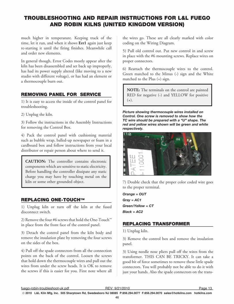
TROUBLESHOOTING AND REPAIR INSTRUCTIONS FOR L&L FUEGO AND ROBIN KILNS (UNITED KINGDOM VERSION)
fuego-robin-troubleshoot-uk.pdf REV:9/21/2010 Page13 2010 L&L Kiln Mfg, Inc. 505 Sharptown Rd, Swedesboro NJ 08085 P:856.294.0077 F:856.294.0070 [email protected] hotkilns.com
much higher in temperature. Keeping track of the time, let it run, and when it shows Err1 again just keep re-starting it until the firing finishes. Meanwhile call and order new elements.
In general though, Error Codes mostly appear after the kiln has been disassembled and set back up improperly, has had its power supply altered (like moving to a new studio with different voltage), or has had an element or a thermocouple burn out.
REMOVING PANEL FOR SERVICE1) It is easy to access the inside of the control panel for troubleshooting.
2) Unplug the kiln.
3) Follow the instructions in the Assembly Instructions for removing the Control Box.
4) Pack the control panel with cushioning material such as bubble wrap, balled-up newspaper or foam in a cardboard box and follow instructions from your local distributor or repair person about where to send it.
CAUTION: The controller contains electronic components which are sensitive to static electricity. Before handling the controller dissipate any static charge you may have by touching metal on the kiln or some other grounded object.
REPLACING ONE-TOUCH™
1) Unplug kiln or turn off the kiln at the fused disconnect switch.
2) Remove the four #6 screws that hold the One-Touch™ in place from the front face of the control panel.
3) Detach the control panel from the kiln body and remove the insulation plate by removing the four screws on the sides of the box.
4) Pull off the spade connectors from all the connection points on the back of the control. Loosen the screws that hold down the thermocouple wires and pull out the wires from under the screw heads. It is OK to remove the screws if this is easier for you. First note where all
the wires go. These are all clearly marked with color coding on the Wiring Diagram.
5) Pull old control out. Put new control in and screw in place with the #6 mounting screws. Replace wires on proper connectors.
6) Reattach the thermocouple wires to the control. Green matched to the Minus (-) sign and the White matched to the Plus (+) sign.
NOTE: The terminals on the control are painted RED for negative (-) and YELLOW for positive (+).
Picture showing thermocouple wires installed on Control. One screw is removed to show how the TC wire should be prepared with a “U” shape. The red and yellow wires shown will be green and white respectively.
7) Double check that the proper color coded wire goes to the proper terminal.
Orange = OUT
Gray = AC1
Green/Yellow = CT
Black = AC2
REPLACING TRANSFORMER1) Unplug kiln.
3) Remove the control box and remove the insulation panel.
3) Using needle nose pliers pull off the wires from the transformer. THIS CAN BE TRICKY. It can take a good bit of force sometimes to remove these little spade connectors. You will probably not be able to do it with just your hands. Also the spade connectors on the trans-
46
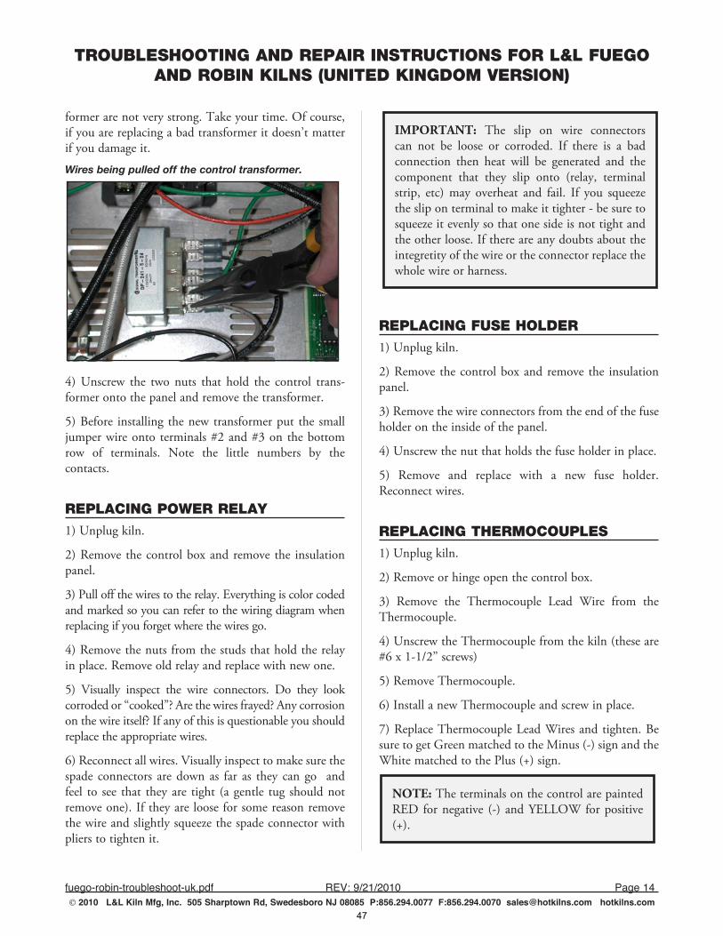
TROUBLESHOOTING AND REPAIR INSTRUCTIONS FOR L&L FUEGO AND ROBIN KILNS (UNITED KINGDOM VERSION)
fuego-robin-troubleshoot-uk.pdf REV:9/21/2010 Page14 2010 L&L Kiln Mfg, Inc. 505 Sharptown Rd, Swedesboro NJ 08085 P:856.294.0077 F:856.294.0070 [email protected] hotkilns.com
former are not very strong. Take your time. Of course, if you are replacing a bad transformer it doesn’t matter if you damage it.
Wires being pulled off the control transformer.
4) Unscrew the two nuts that hold the control trans-former onto the panel and remove the transformer.
5) Before installing the new transformer put the small jumper wire onto terminals #2 and #3 on the bottom row of terminals. Note the little numbers by the contacts.
REPLACING POWER RELAY1) Unplug kiln.
2) Remove the control box and remove the insulation panel.
3) Pull off the wires to the relay. Everything is color coded and marked so you can refer to the wiring diagram when replacing if you forget where the wires go.
4) Remove the nuts from the studs that hold the relay in place. Remove old relay and replace with new one.
5) Visually inspect the wire connectors. Do they look corroded or “cooked”? Are the wires frayed? Any corrosion on the wire itself? If any of this is questionable you should replace the appropriate wires.
6) Reconnect all wires. Visually inspect to make sure the spade connectors are down as far as they can go and feel to see that they are tight (a gentle tug should not remove one). If they are loose for some reason remove the wire and slightly squeeze the spade connector with pliers to tighten it.
IMPORTANT: The slip on wire connectors can not be loose or corroded. If there is a bad connection then heat will be generated and the component that they slip onto (relay, terminal strip, etc) may overheat and fail. If you squeeze the slip on terminal to make it tighter - be sure to squeeze it evenly so that one side is not tight and the other loose. If there are any doubts about the integretity of the wire or the connector replace the whole wire or harness.
REPLACING FUSE HOLDER1) Unplug kiln.
2) Remove the control box and remove the insulation panel.
3) Remove the wire connectors from the end of the fuse holder on the inside of the panel.
4) Unscrew the nut that holds the fuse holder in place.
5) Remove and replace with a new fuse holder. Reconnect wires.
REPLACING THERMOCOUPLES 1) Unplug kiln.
2) Remove or hinge open the control box.
3) Remove the Thermocouple Lead Wire from the Thermocouple.
4) Unscrew the Thermocouple from the kiln (these are #6 x 1-1/2” screws)
5) Remove Thermocouple.
6) Install a new Thermocouple and screw in place.
7) Replace Thermocouple Lead Wires and tighten. Be sure to get Green matched to the Minus (-) sign and the White matched to the Plus (+) sign.
NOTE: The terminals on the control are painted RED for negative (-) and YELLOW for positive (+).
47
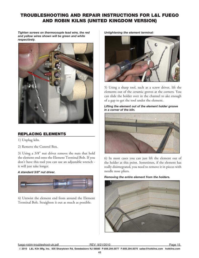
TROUBLESHOOTING AND REPAIR INSTRUCTIONS FOR L&L FUEGO AND ROBIN KILNS (UNITED KINGDOM VERSION)
fuego-robin-troubleshoot-uk.pdf REV:9/21/2010 Page15 2010 L&L Kiln Mfg, Inc. 505 Sharptown Rd, Swedesboro NJ 08085 P:856.294.0077 F:856.294.0070 [email protected] hotkilns.com
Tighten screws on thermocouple lead wire, the red and yellow wires shown will be green and white respectively.
REPLACING ELEMENTS1) Unplug kiln.
2) Remove the Control Box.
3) Using a 3/8” nut driver remove the nuts that hold the element end onto the Element Terminal Bolt. If you don’t have this tool you can use an adjustable wrench - it will just take longer.
A standard 3/8” nut driver.
4) Untwist the element end from around the Element Terminal Bolt. Straighten it out as much as possible.
Untightening the element terminal:
5) Using a sharp tool, such as a screw driver, lift the elements out of the ceramic groves at the corners. You can slide the holder over in the channel to ake enough of a gap to get the tool under the element.
Lifting the element out of the element holder groove in a corner of the kiln.
6) In most cases you can just lift the element out of the holder at this point. Sometimes, if the element has really disintegrated, you need to remove it in pieces with needle nose pliers.
Removing the entire element from the holders.
48
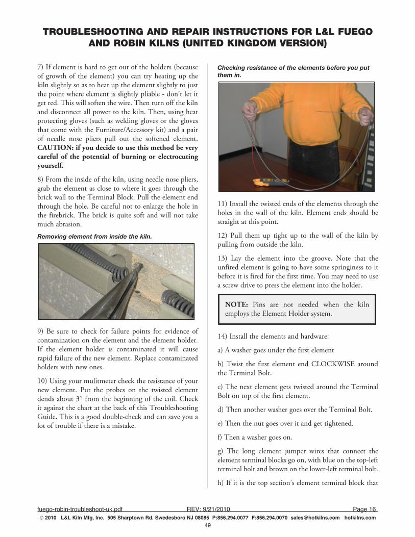
TROUBLESHOOTING AND REPAIR INSTRUCTIONS FOR L&L FUEGO AND ROBIN KILNS (UNITED KINGDOM VERSION)
fuego-robin-troubleshoot-uk.pdf REV:9/21/2010 Page16 2010 L&L Kiln Mfg, Inc. 505 Sharptown Rd, Swedesboro NJ 08085 P:856.294.0077 F:856.294.0070 [email protected] hotkilns.com
7) If element is hard to get out of the holders (because of growth of the element) you can try heating up the kiln slightly so as to heat up the element slightly to just the point where element is slightly pliable - don’t let it get red. This will soften the wire. Then turn off the kiln and disconnect all power to the kiln. Then, using heat protecting gloves (such as welding gloves or the gloves that come with the Furniture/Accessory kit) and a pair of needle nose pliers pull out the softened element. CAUTION: if you decide to use this method be very careful of the potential of burning or electrocuting yourself.
8) From the inside of the kiln, using needle nose pliers, grab the element as close to where it goes through the brick wall to the Terminal Block. Pull the element end through the hole. Be careful not to enlarge the hole in the firebrick. The brick is quite soft and will not take much abrasion.
Removing element from inside the kiln.
9) Be sure to check for failure points for evidence of contamination on the element and the element holder. If the element holder is contaminated it will cause rapid failure of the new element. Replace contaminated holders with new ones.
10) Using your mulitmeter check the resistance of your new element. Put the probes on the twisted element dends about 3” from the beginning of the coil. Check it against the chart at the back of this Troubleshooting Guide. This is a good double-check and can save you a lot of trouble if there is a mistake.
Checking resistance of the elements before you put them in.
11) Install the twisted ends of the elements through the holes in the wall of the kiln. Element ends should be straight at this point.
12) Pull them up tight up to the wall of the kiln by pulling from outside the kiln.
13) Lay the element into the groove. Note that the unfired element is going to have some springiness to it before it is fired for the first time. You may need to use a screw drive to press the element into the holder.
NOTE: Pins are not needed when the kiln employs the Element Holder system.
14) Install the elements and hardware:
a) A washer goes under the first element
b) Twist the first element end CLOCKWISE around the Terminal Bolt.
c) The next element gets twisted around the Terminal Bolt on top of the first element.
d) Then another washer goes over the Terminal Bolt.
e) Then the nut goes over it and get tightened.
f) Then a washer goes on.
g) The long element jumper wires that connect the element terminal blocks go on, with blue on the top-left terminal bolt and brown on the lower-left terminal bolt.
h) If it is the top section’s element terminal block that
49
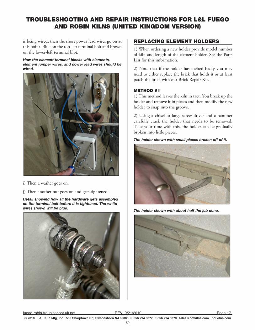
TROUBLESHOOTING AND REPAIR INSTRUCTIONS FOR L&L FUEGO AND ROBIN KILNS (UNITED KINGDOM VERSION)
fuego-robin-troubleshoot-uk.pdf REV:9/21/2010 Page17 2010 L&L Kiln Mfg, Inc. 505 Sharptown Rd, Swedesboro NJ 08085 P:856.294.0077 F:856.294.0070 [email protected] hotkilns.com
is being wired, then the short power lead wires go on at this point. Blue on the top-left terminal bolt and brown on the lower-left terminal blot.
How the element terminal blocks with elements, element jumper wires, and power lead wires should be wired.
i) Then a washer goes on.
j) Then another nut goes on and gets tightened.
Detail showing how all the hardware gets assembled on the terminal bolt before it is tightened. The white wires shown will be blue.
REPLACING ELEMENT HOLDERS1) When ordering a new holder provide model number of kiln and length of the element holder. See the Parts List for this information.
2) Note that if the holder has melted badly you may need to either replace the brick that holds it or at least patch the brick with our Brick Repair Kit.
METHOD #11) This method leaves the kiln in tact. You break up the holder and remove it in pieces and then modify the new holder to snap into the groove.
2) Using a chisel or large screw driver and a hammer carefully crack the holder that needs to be removed. Take your time with this, the holder can be gradually broken into little pieces.
The holder shown with small pieces broken off of it.
The holder shown with about half the job done.
50
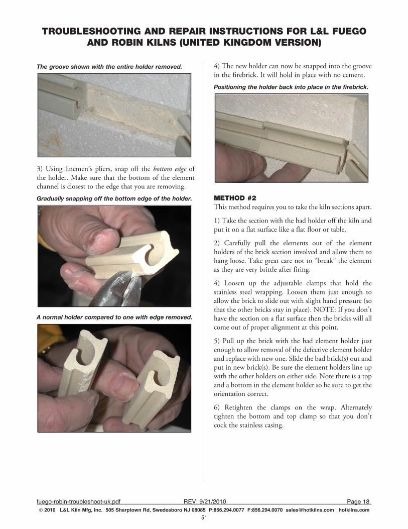
TROUBLESHOOTING AND REPAIR INSTRUCTIONS FOR L&L FUEGO AND ROBIN KILNS (UNITED KINGDOM VERSION)
fuego-robin-troubleshoot-uk.pdf REV:9/21/2010 Page18 2010 L&L Kiln Mfg, Inc. 505 Sharptown Rd, Swedesboro NJ 08085 P:856.294.0077 F:856.294.0070 [email protected] hotkilns.com
The groove shown with the entire holder removed.
3) Using linemen’s pliers, snap off the bottom edge of the holder. Make sure that the bottom of the element channel is closest to the edge that you are removing.
Gradually snapping off the bottom edge of the holder.
A normal holder compared to one with edge removed.
4) The new holder can now be snapped into the groove in the firebrick. It will hold in place with no cement.
Positioning the holder back into place in the firebrick.
METHOD #2This method requires you to take the kiln sections apart.
1) Take the section with the bad holder off the kiln and put it on a flat surface like a flat floor or table.
2) Carefully pull the elements out of the element holders of the brick section involved and allow them to hang loose. Take great care not to “break” the element as they are very brittle after firing.
4) Loosen up the adjustable clamps that hold the stainless steel wrapping. Loosen them just enough to allow the brick to slide out with slight hand pressure (so that the other bricks stay in place). NOTE: If you don’t have the section on a flat surface then the bricks will all come out of proper alignment at this point.
5) Pull up the brick with the bad element holder just enough to allow removal of the defective element holder and replace with new one. Slide the bad brick(s) out and put in new brick(s). Be sure the element holders line up with the other holders on either side. Note there is a top and a bottom in the element holder so be sure to get the orientation correct.
6) Retighten the clamps on the wrap. Alternately tighten the bottom and top clamp so that you don’t cock the stainless casing.
51
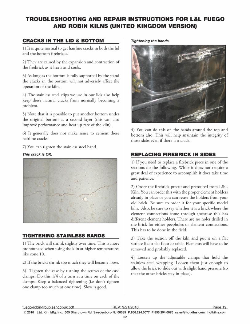
TROUBLESHOOTING AND REPAIR INSTRUCTIONS FOR L&L FUEGO AND ROBIN KILNS (UNITED KINGDOM VERSION)
fuego-robin-troubleshoot-uk.pdf REV:9/21/2010 Page19 2010 L&L Kiln Mfg, Inc. 505 Sharptown Rd, Swedesboro NJ 08085 P:856.294.0077 F:856.294.0070 [email protected] hotkilns.com
CRACKS IN THE LID & BOTTOM1) It is quite normal to get hairline cracks in both the lid and the bottom firebricks.
2) They are caused by the expansion and contraction of the firebrick as it heats and cools.
3) As long as the bottom is fully supported by the stand the cracks in the bottom will not adversely affect the operation of the kiln.
4) The stainless steel clips we use in our lids also help keep these natural cracks from normally becoming a problem.
5) Note that it is possible to put another bottom under the original bottom as a second layer (this can also improve performance and heat up rate of the kiln).
6) It generally does not make sense to cement these hairline cracks.
7) You can tighten the stainless steel band.
This crack is OK.
TIGHTENING STAINLESS BANDS1) The brick will shrink slightly over time. This is more pronounced when using the kiln at higher temperatures like cone 10.
2) If the bricks shrink too much they will become loose.
3) Tighten the case by turning the screws of the case clamps. Do this 1/4 of a turn at a time on each of the clamps. Keep a balanced tightening (i.e don’t tighten one clamp too much at one time). Slow is good.
Tightening the bands.
4) You can do this on the bands around the top and bottom also. This will help maintain the integrity of those slabs even if there is a crack.
REPLACING FIREBRICK IN SIDES1) If you need to replace a firebrick piece in one of the sections do the following. While it does not require a great deal of experience to accomplish it does take time and patience.
2) Order the firebrick precut and prerouted from L&L Kiln. You can order this with the proper element holders already in place or you can reuse the holders from your old brick. Be sure to order it for your specific model kiln. Also, be sure to say whether it is a brick where the element connections come through (because this has different element holders. There are no holes drilled in the brick for either peepholes or element connections. This has to be done in the field.
3) Take the section off the kiln and put it on a flat surface like a flat floor or table. Elements will have to be removed and probably replaced.
4) Loosen up the adjustable clamps that hold the stainless steel wrapping. Loosen them just enough to allow the brick to slide out with slight hand pressure (so that the other bricks stay in place).
52
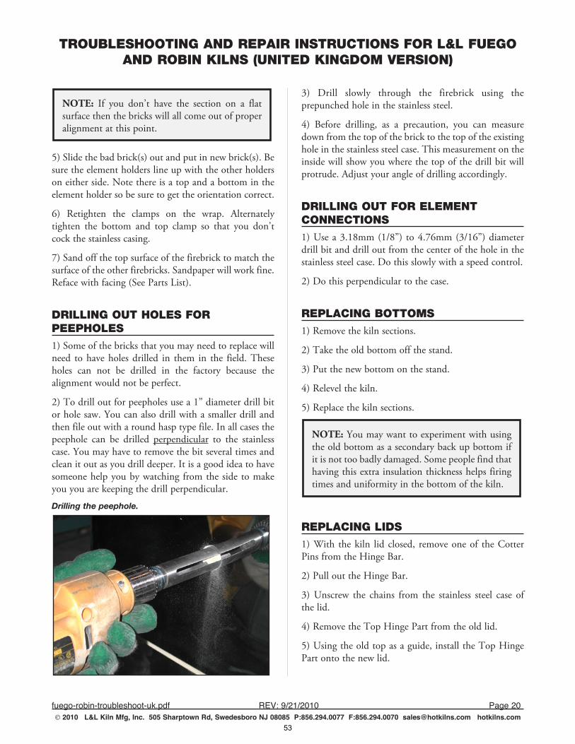
TROUBLESHOOTING AND REPAIR INSTRUCTIONS FOR L&L FUEGO AND ROBIN KILNS (UNITED KINGDOM VERSION)
fuego-robin-troubleshoot-uk.pdf REV:9/21/2010 Page20 2010 L&L Kiln Mfg, Inc. 505 Sharptown Rd, Swedesboro NJ 08085 P:856.294.0077 F:856.294.0070 [email protected] hotkilns.com
NOTE: If you don’t have the section on a flat surface then the bricks will all come out of proper alignment at this point.
5) Slide the bad brick(s) out and put in new brick(s). Be sure the element holders line up with the other holders on either side. Note there is a top and a bottom in the element holder so be sure to get the orientation correct.
6) Retighten the clamps on the wrap. Alternately tighten the bottom and top clamp so that you don’t cock the stainless casing.
7) Sand off the top surface of the firebrick to match the surface of the other firebricks. Sandpaper will work fine. Reface with facing (See Parts List).
DRILLING OUT HOLES FOR PEEPHOLES1) Some of the bricks that you may need to replace will need to have holes drilled in them in the field. These holes can not be drilled in the factory because the alignment would not be perfect.
2) To drill out for peepholes use a 1” diameter drill bit or hole saw. You can also drill with a smaller drill and then file out with a round hasp type file. In all cases the peephole can be drilled perpendicular to the stainless case. You may have to remove the bit several times and clean it out as you drill deeper. It is a good idea to have someone help you by watching from the side to make you you are keeping the drill perpendicular.
Drilling the peephole.
3) Drill slowly through the firebrick using the prepunched hole in the stainless steel.
4) Before drilling, as a precaution, you can measure down from the top of the brick to the top of the existing hole in the stainless steel case. This measurement on the inside will show you where the top of the drill bit will protrude. Adjust your angle of drilling accordingly.
DRILLING OUT FOR ELEMENT CONNECTIONS1) Use a 3.18mm (1/8”) to 4.76mm (3/16”) diameter drill bit and drill out from the center of the hole in the stainless steel case. Do this slowly with a speed control.
2) Do this perpendicular to the case.
REPLACING BOTTOMS1) Remove the kiln sections.
2) Take the old bottom off the stand.
3) Put the new bottom on the stand.
4) Relevel the kiln.
5) Replace the kiln sections.
NOTE: You may want to experiment with using the old bottom as a secondary back up bottom if it is not too badly damaged. Some people find that having this extra insulation thickness helps firing times and uniformity in the bottom of the kiln.
REPLACING LIDS1) With the kiln lid closed, remove one of the Cotter Pins from the Hinge Bar.
2) Pull out the Hinge Bar.
3) Unscrew the chains from the stainless steel case of the lid.
4) Remove the Top Hinge Part from the old lid.
5) Using the old top as a guide, install the Top Hinge Part onto the new lid.
53
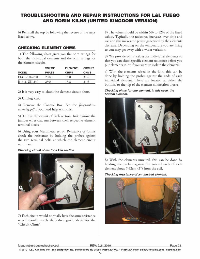
TROUBLESHOOTING AND REPAIR INSTRUCTIONS FOR L&L FUEGO AND ROBIN KILNS (UNITED KINGDOM VERSION)
fuego-robin-troubleshoot-uk.pdf REV:9/21/2010 Page21 2010 L&L Kiln Mfg, Inc. 505 Sharptown Rd, Swedesboro NJ 08085 P:856.294.0077 F:856.294.0070 [email protected] hotkilns.com
6) Reinstall the top by following the reverse of the steps listed above.
CHECKING ELEMENT OHMS1) The following chart gives you the ohm ratings for both the individual elements and the ohm ratings for the element circuits. VOLTS/ ELEMENT CIRCUITMODEL PHASE OHMS OHMS
F1418-UK-230 230/1 15.8 31.6R1618-UK-230 230/1 15.8 31.6
2) It is very easy to check the element circuit ohms.
3) Unplug kiln.
4) Remove the Control Box. See the fuego-robin-assembly.pdf if you need help with this.
5) To test the circuit of each section, first remove the jumper wires that run between their respective element terminal blocks.
6) Using your Multimeter set on Resistance or Ohms check the resistance by holding the probes against the two terminal bolts at which the element circuit terminate.
Checking circuit ohms for a kiln section.
7) Each circuit would normally have the same resistance which should match the values given above for the “Circuit Ohms”.
8) The values should be within 6% to 12% of the listed values. Typically the resistance increases over time and use and this makes the power generated by the elements decrease. Depending on the temperature you are firing to you may get away with a wider variation.
9) We provide ohms values for individual elements so that you can check specific element resistance before you put elements in or if you want to isolate the elements.
a) With the elements wired in the kiln, this can be done by holding the probes against the ends of each individual element. These are located at either the bottom, or the top of the element connection blocks.
Checking ohms for one element, in this case, the bottom element.
b) With the elements unwired, this can be done by holding the probes against the twisted ends of each element about 7.62cm (3”) from the coil.
Checking resistance of an unwired element.
54

NOTES
notes.pdf REV:9/17/2010 Page1 2010 L&L Kiln Mfg, Inc. 505 Sharptown Rd, Swedesboro NJ 08085 P:856.294.0077 F:856.294.0070 [email protected] hotkilns.com
55
2010 L&L Kiln Mfg, Inc.
L&L Kiln Mfg505 Sharptown RoadSwedesboro, NJ 08085Phone: 856.294.0077Fax: 856.294.0070Email: [email protected]
Made in USA
MODEL NUMBER: _____________________SERIAL NUMBER: _____________________VOLTAGE: ________ PHASE: ____________AMPS: ___________ WATTS: ____________
56

Potclays Ltd Brickkiln Lane, Etruria
Stoke-on-Trent Staffordshire ST4 7BP
Phone: 01782 219816
Fax: 01782 286506 Email: [email protected]
Web: www.potclays.co.uk
FOR PARTS AND SERVICE CONTACT POTCLAYS LTD
65 years of excellence
57