For customers, We do our best - pakmarkas.lt
74
Transcript of For customers, We do our best - pakmarkas.lt


For customers, We do our best
MOTORS • GEARS • CONTROLS
"Antonio Stradivari", the famous violinist family, Started making fine Violins
from the year 1644 to 1937. For Three hundred years, their violins still have the
best reputation, and as time continues to pass, the more precious they become.
The sweet tender sound quality and absolute accuracy of the violin are priceless
treasure of the world. It is a musical instrument that can express the deepest
passions of human beings. The touching tune of the violin brings great pleasure to
millions.
We know that accurate design, The best in wood selection, seal, paint, string
and violin bridge , f sound hole, are the necessary elements that make for an
exquisite violin. Only those people with professional crafting exper tise and
experience, along with the quest to provide a lively expression in music, can
reach such a goal in perfection.
This is the same spiritual request that makes Maxway products. Through our
past 20 years of manufacturing experience, our goal has been to constantly
improve the characteristics of our products, which offer our customers flawless
high efficiency, Low nose, and long life satisfaction.
Our professional expertise and experience are your most trusted guarantee!
For the customer, We always do our best.
1

INDEX ContentIntroduction Selection of Motor Selection of AC Motor and Gear Basic Calculation of Motor Capacity
Gear Reducer & Induction MotorInduction Motor Reversible Motor Induction Variable-speed Motor Reversible Variable-speed Motor Brake MotorVariable Speed Motor with Electro-Magnetic Brake MotorVariable-speed Controller Dimension Figure Connection Diagram Wiring Diagram for AC 1ø & 3ø Electronic Brake Straight Gear Reducer Hollow Shaft Worm Gear
Brushless D.C. Motor
Gear Reducer & D.C. MotorPermanent Magnet D.C. Motor Series MotorVariable-speed Controller
Parts & AccessoriesElectromagnetic Brake Carbon Brush Seat Carbon Brush Metallurgy Powder PartsMotor Shaft
Mold Making
8
1346
21
36
404142
46
496264
697071
72
6668
22 23
2

HOW TO SELECT A MOTOR
INDUCTIONMOTOR
• Continuous rating
• Starting Torque
Rated Torque
• For general purpose
• Great selections
• Wide application
=0.7~1.0
=0.8~1.2
• Rating for 30 minutes
• Starting Torque Rated Torque
• Suitable for frequent rotation reversal
• Easily switched to reverse rotation • Built-in breake• Small overrun with moderate retention
• Safe braking power
• High braking retention
• Great selections
• Combination of motor
and tachometer dynamo
• Closed-circuit control motor
• Easy control of speed and
simple wiring
• Variable speed
• High braking power
• High power
• High efficiency
• Suitable for industrial
machinery
25W150WINDUCTION
MOTOR
Brake &Retention
PowerSupply
Variationof Speed
TurningDirection
MotorTypes
Outputof Motor
4W-120W
4W-90W
4W-120W
4W-120WVARIABLE
SPEEDMOTOR
FreeVariationof Speed
Brake &Retention
RotationReversal
BRAKEMOTOR
FrequentRotationReversal
REVERSIBLEMOTOR
Retention
FixedSpeed
WithoutRetention
SingleDirection
ThreePhase
SinglePhase
Motor
3
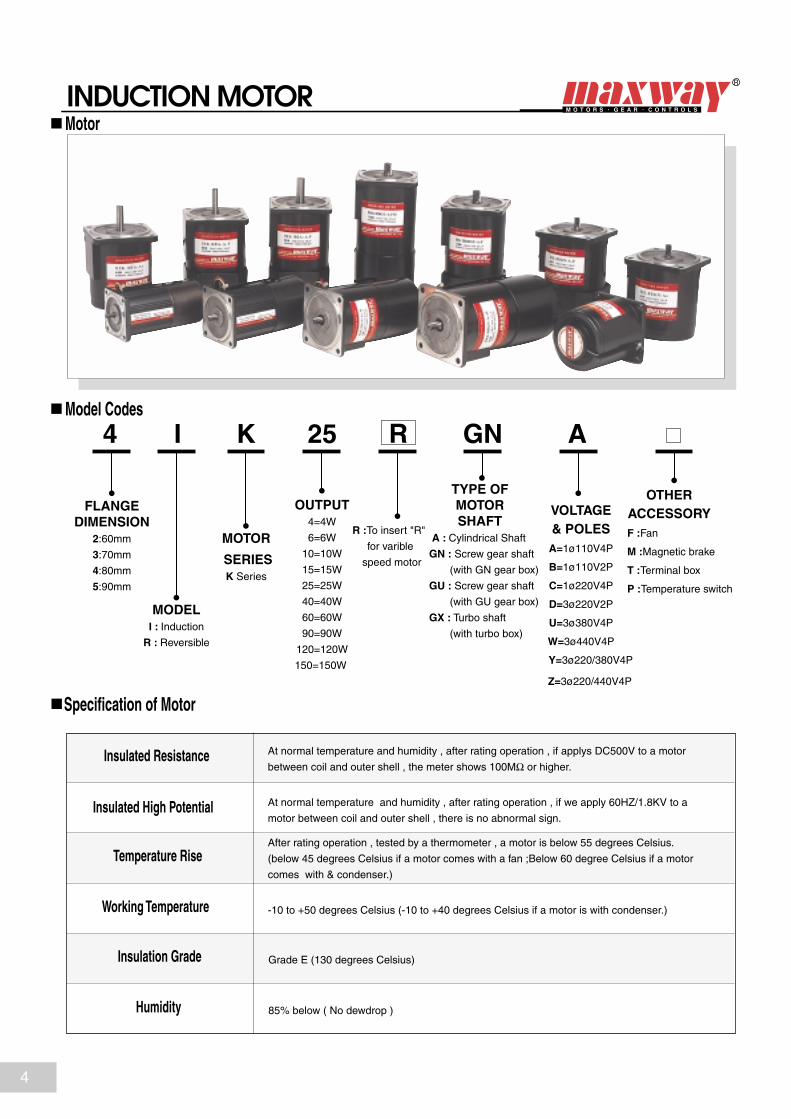
INDUCTION MOTOR
FLANGEDIMENSION
2:60mm
3:70mm
4:80mm
5:90mm
MOTOR
SERIESK Series
OUTPUT4=4W
6=6W
10=10W
15=15W
25=25W
40=40W
60=60W
90=90W
120=120W
150=150W
MODELI : Induction
R : Reversible
R :To insert "R"
for varible
speed motor
TYPE OFMOTORSHAFT
A : Cylindrical Shaft
GN : Screw gear shaft
(with GN gear box)
GU : Screw gear shaft
(with GU gear box)
GX : Turbo shaft
(with turbo box)
OTHERACCESSORY
F :Fan
M :Magnetic brake
T :Terminal box
P :Temperature switch
VOLTAGE& POLESA=1ø110V4P
B=1ø110V2P
C=1ø220V4P
D=3ø220V2P
U=3ø380V4P
W=3ø440V4P
Y=3ø220/380V4P
Z=3ø220/440V4P
AGN25KI4 R
Insulated Resistance
Insulated High Potential
Temperature Rise
Working Temperature
Insulation Grade
Humidity
At normal temperature and humidity , after rating operation , if applys DC500V to a motor
between coil and outer shell , the meter shows 100MΩ or higher.
At normal temperature and humidity , after rating operation , if we apply 60HZ/1.8KV to a
motor between coil and outer shell , there is no abnormal sign.
After rating operation , tested by a thermometer , a motor is below 55 degrees Celsius.
(below 45 degrees Celsius if a motor comes with a fan ;Below 60 degree Celsius if a motor
comes with & condenser.)
-10 to +50 degrees Celsius (-10 to +40 degrees Celsius if a motor is with condenser.)
Grade E (130 degrees Celsius)
85% below ( No dewdrop )
Model Codes
Specification of Motor
Motor
4

GEAR HEAD
4 GN 100 K
DIMENSION2: 60mm
3: 70mm
4: 80mm
5: 90mm
GEAR TYPEGN: Common gear box
GU: Reinforced gear box
GX: Heavy load gear box
REDUCTION RATIO10X Means
Medium gear
GEAR BEARING RATIOK = Ball bearing
B = Metal bearing
KB = Square gear head
( without-flange )
3
0.92GN (K)
3GN (K)
3GN (K)
4GN (K)
5GN (K)
5GN (K)
5GU (K)
5GU (K)
6W
Suitableto motor
10W
15W
25W
40W
60W
90W
120W
3.6
1.0
5
1.5
6
1.8
7.5
2.3
10
3.0
12.5
3.8
15
4.5
18
5.4
20 25
7.0
30
8.3
36
10
40
11
50
14
60
16
75
19
90
23
100
25
120
25
150
25
180
25
10X
--
1.9 2.2 3.2 3.8 4.9 6.4 8 9.7 11.1 15 18 29 22 26 40 40 40 40 40 40 40 --
2.2 2.6 3.7 4.4 5.5 7.2 9.1 11 13 17 21 24 29 34 41 47 50 50 50 50 50 --
3.7 4.4 6.1 7.3 9.1 12 15 18 22 28 34 44 49 61 67 79 80 80 80 80 80 --23
6.0 7.3 10 12 15 20 25 30 36 47 56 68 75 94 100 100 100 100 100 100 100 --
9.0 11 15 18 23 30 37 45 54 69 83 100 111 139 150 150 150 150 150 150 150 --
13 15 21 26 32 40 50 60 72 93 111 134 148 185 200 200 200 200 200 200 200 --74
13 21.6 30 36 45 60 75 90 108 150 180 216 240 250 250 250 250 250 250 250 250 --120
RatioItemGear Head
5GX K gear head is partially available, maximum torque is 300 kg/cm.Motor RPM /reduction ratio of gear head = Gear head shaft RPM.
List of reduction ratio and torque of reducers for different motors
Model Codes
Gear Head
Currently, we produce mainly 2 types of reducer GN and GU. GN type is for common workload of gear head.GU is reinforced type For 5GU gear head, we can supply the motor either with flange ( 5GU K TYPE ) and without flange ( 5GU KB TYPE )
a white background indicates rotation in the opposite direction
5

CALCULATION OF MOTOROUTPUT CAPACITY
Example: If a reducer works at the same workload continuouslyfor 8 hours a day ,its service factor is 1.0. When the reducer operates within the allowed torpue ,its durable period is :•5000 hours for K type (ball bearing) , outer temperature of reducer is below 80° C.
•2000 hours for B type (metal bearing), outer temperature of reducer is below 50° C.
But if a reducer works for 24 hours a day its service factor is 1.5. Within the allowed torque, its durable period will be decreased by 1/1.5. If one wants a 4GN K gear head to maintain durable period 5000 hours , one has to make it work below 1/1.5 of its allowed torque. Or one can use a reducer with higher torque to enhance the motor output.
1. Winding Up/Lifting Up the Load
2. Driving Flywheel Load
3. Belt Conveyor
4. Traveling on Flat Surface
Service Factor of Reducer Type of Load
Motor Motor
w
Motor
wBeltwheel
Motor
w
Service FactorType of Load 5h/day 8h/day 24h/day
Constant 0.8 1.0 1.5
Light Impact 1.2 1.5 2.0
Medium Impact 1.5 2.0 2.5
Heavy Impact 2.0~2.5 2.0~3.0 3.0~3.5
Type of Load Application
Pg = 1.027NT (W)
T (kgf.m) N : Speed (r/min) T : Torque (kgf.m)GD2 : Flywheel effect (kgf.m2 ) t : Time (sec.)pg : Power required(w)
.2GD N
t375
W : Load (kgf) V : Speed (m/min) µ : Friction coeffciency
Pg = (W) µwv6.12
Pg = (W)
W : Load (kgf) v : Speed (m/min) n : Efficency (%)pg:Power required(w)
.wv6.12
100
Pg = ( P1 + P2 + P3 ) (W)
where No Load power P1 = 9.8µwv (W)
Horizontal Power P2 = (W)
Vertical Power P3 =± (W)
: Length of conveyer (m) W : Weight of belt (unit) (kgf/m) µ : Friction coeffciency V : Belt speed (m/sec) Q : Weight capacity (kgf/h) : Efficency (%) H : Height between both conveyor end
100
µQ367
QH367
Constant
LightImpact
MediumImpact
HeavyImpact
Belt Conveyer , Film Winding,One-way operation
Start/Stop/Cam operation
Instant Reverse operation with Reversible MotorInstant Stall operation with BrakePack
Repetition of Medium ImpactInstant Stall of the motor at vibrating material
6

WORKLOAD OF REDUCER
A reducer's torque will rise proportionally with reduction ratio. But the gear material as well as some other factors may limit the torque. Please refer to the following chart for maximum allowable torque at different reduction ratios with each model.
Please note that the calculated Overhung Workload (W) shall not exceed the limit listed above. If the actual Overhung Workload exceeds the limit , the bearing may wear out prematurely , and the shaft may warp or even break.
2GN-B2GN-K
3GN-B3GN-K
4GN-B4GN-K
5GN-B5GN-K
5GU-K
5GU-KB
5GX-K
512
10
15
15
20
25
30
40
40
60
25
50
80
100
200
200
300
3
4
5
10
15
15
15
818
15
25
25
30
35
45
60
60
80
Item
Limit ofMaximum
Torque(kg . cm) 10 mm from
the tip of shaft point A
20 mm from the tip of
shaft point B
Limit ofThrust
Workload(kg)
Limit of Overhung Workload
200
300
160
140
120
100
80
60
40
20
0 20 40 60 80 100 120
2GN-K
3GN-K
4GN-K
5GN-K
5GX
5GU-K .KB
Drive
Chain or cog belt
Gear
V-belt
Parallel belt
K
1
1. 25
1. 5
2. 5
Overhung workload W =
W: Overhung workload (kg) K : Workload coefficient according to drive T :Transmission efficiency (kg . cm) at reducer output shaft f : Durable period coefficient r : Effective radius (cm) of gear , roller , or pulley , etc.
K x T x fr
A point is 10 mm from the tip end of the shaft.B point is 20 mm from the tip end of the shaft.
Formula to Calculate Overhung Workload :
AB
Thrust Workload Limit and Overhung Workload Limit
( F ) Thrust workload
( W ) overhung workload
Maximum Allowable TorqueSpecification
Ng : Gearhead Speed (rpm)Nm: Motor Speed (rpm) i : Gear RatioTg : Gearhead Output Torque (kg.cm)Tm : Motor Output Torque (kg,cm) : Gear Efficiency
How to Calculate torque Direct assembly of gearhead
Torque(kg . cm)
(Reduction Ratio)
7

Type Output Voltage Frequency Poles SpeedD u t y
Starting Torque Rated Torque Rated Current Capacitor
CylindricalShaft Gear Shaft ( W ) ( V ) ( H z ) ( P ) ( r p m ) ( g . c m ) ( g . c m ) ( A ) ( µ f )
6W Motor Dimensions unit : m m
2GN Gear Head Dimensions unit : m m
2GN2GN K
6 W
2IK6A-A 2IK6GN-A 6 1Ø110 4 1450/1750 0.20 2.550/60
2IK6A-C 2IK6GN-C 6 4 1450/1750IK Ser ise
CONT.
RK Ser ise30Min.
0.10 0.71Ø220 50/60
2RK6A-A 2RK6GN-A 6 4 1450/1750 400
410
410
0.24 31Ø110 50/60
2RK6A-C 2RK6GN-C 6 4 1450/1750 400 0.12
370
370
370
370 0.81Ø220 50/60
R A T I O
M A X T o r q u e
k g . c m
E F F.B
K
3
0.9
3.6
1.0
5
1.5
6
1.8
7.5
2.3
10
3.0
12.5
3.8
15
4.5
18
5.4
20 25
7.0
30
8.3
36
10
40
11
50
14
60
16
75
19
90
23
100
25
120
25
150
25
180
25
10X
--
68%
81%
65%
75%
63%
70%
6W Motor Specification
6W Motor with 2GN Gear Head, Maximum Permissible Load and Efficiency
INDUCTIONREVERSIBLE MOTOR
a white background indicates rotation in the opposite direction
K S e r i e sSingle Phase 1 1 0 / 2 2 0
Single Phase Connection Diagrams( )Gear screw dimension Shaft diameter: ø5.5 Pressure angle: 20° Module: 0.5Number of teeth: 8 Plane key: 1x10l Weight: 0.7kg
2GN3-18 L=322GN20-180 L=42
Weight : 0.4kg Weight : 0.2kg2GN10XPlane key 1x12l
Ø59
76(13)100 (89)24
6.5
2.5300mm
Ø6h7
Ø54h
7
60
22.5˚
Ø70
4-Ø5.50.5
S
Capacitor
AC CW
CCW
red(main)
white
black(blue)
S AC
110(220)V 110(220)V
C W
CCW
red(main)
white
black(blue)
Capacitor
4-Ø5.5
60
Ø70
Ø18
Ø8h7
L 32
L + 32
5
12 110
Ø54h
7
2
144-Ø5.5
60
Ø70
40
26
8

Type Output Voltage Frequency Poles Variable SpeedRangeD u t y
Starting Torque Rated Torque Rated Current Capacitor
Gear Shaft ( W ) ( V ) ( H z ) ( P ) ( r p m ) ( g . c m ) ( g . c m ) ( A ) ( µ f )
6W Variable Speed Motor Dimensions unit : m m
2GN Gear Head Dimensions unit : m m
2GN2GN K
CylindricalShaft
6 W
2IK6RA-A 2IK6RGN-A 6 1Ø110 4 90/1400/1700 0.24 2.550/60
2IK6RA-C 2IK6RGN-C 6 4 90/1400/1700IK Ser iesCONT.
RK Ser ies30Min.
0.12 0.71Ø220 50/60
2RK6RA-A 2RK6RGN-A 6 4 90/1400/1700 390
380
380
0.24 31Ø110 50/60
2RK6RA-C 2RK6RGN-C 6 4 90/1400/1700 390 0.12
250~330
250~330
310~320
310~320 0.81Ø220 50/60
R A T I O
M A X T o r q u e
k g . c m
E F F.B
K
3
0.9
3.6
1.0
5
1.5
6
1.8
7.5
2.3
10
3.0
12.5
3.8
15
4.5
18
5.4
20 25
7.0
30
8.3
36
10
40
11
50
14
60
16
75
19
90
23
100
25
120
25
150
25
180
25
10X
--
68%
81%
65%
75%
63%
70%
6W Motor and Speed Controller Specification
6W Motor with 2GN Gear Head, Maximum Permissible Load and Efficiency
INDUCTIONREVERSIBLE VARIABLE SPEED MOTOR
a white background indicates rotation in the opposite direction
K S e r i e sSingle Phase 1 1 0 / 2 2 0
Shaft diameter: ø5.5 Pressure angle: 20° Module: 0.5 Number of teeth: 8 Plane key: 1x10l Weight: 0.7kg
2GN3-18 L=322GN20-180 L=42Plane key :1x12l Weight : 0.4kg Weight : 0.2kg2GN10X
To Choose a Controller , Please Refer to Page 36.
For Controller's Circuit Diagram , Please Refer to Page 38.
4-Ø5.5
60
Ø70 Ø54h
7
2
144-Ø5.5
60
Ø70
40
26
Ø59
Ø47
7611
87 13
2.50.5
7
Ø6h7
Ø54h
7
60
22.5˚
Ø70
300mm300mm
100
4-Ø5.5
Ø18
Ø8h7
L 32
L + 32
5
12 110
9

Type Output Voltage Frequency Poles SpeedD u t y
Starting Torque Rated Torque Rated Current Capacitor
Gear Shaft ( W ) ( V ) ( H z ) ( P ) ( r p m ) ( g . c m ) ( g . c m ) ( A ) ( µ f )
15W Motor Dimensions unit : m m
3GN Gear Head Dimensions unit : m m
3GN3GN K
CylindricalShaft
1 5 W
3IK15A-A 3IK15GN-A 15 1Ø110 4 1450/1750 0.34 450/60
3IK15A-C 3IK15GN-C 15 4 1450/1750IK Ser iesCONT.
RK Ser ies
30Min.
0.17 11Ø220 50/60
3RK15A-A 3RK15GN-A 15 4 1450/1750 900
900
900
0.52 51Ø110 50/60
3RK15A-C 3RK15GN-C 15 4 1450/1750 900 0.29
900
900
900
900 1.21Ø220 50/60
R A T I O
M A X T o r q u e
k g . c m
E F F.B
K
3
2.2
3.6
2.6
5
3.7
6
4.4
7.5
5.5
10
7.2
12.5
9.1
15
11
18
13
20 25
17
30
21
36
24
40
29
50
34
60
41
75
47
90
50
100
50
120
50
150
50
180
50
10X
--
68%
81%
65%
75%
63%
70%
15W Motor Specification
15W Motor with 3GN Gear Head, Maximum Permissible Load and Efficiency
a white background indicates rotation in the opposite direction
K S e r i e sSingle Phase 1 1 0 / 2 2 0
Single Phase Connection Diagrams( )Gear screw dimension Shaft diameter: ø6.6 Pressure angle: 20° Module: 0.5Number of teeth: 10 Plane key: 1x15l Weight: 1.1kg
3GN3-18 L=32Square key: 4x4x20l
3GN20-180 L=42Square key: 4x4x25l
Weight : 0.55kg Weight : 0.3kg3GN10X
INDUCTIONREVERSIBLE MOTOR
Ø69
80(13)112 (93)32
6.52.5
0.5
300mm
Ø6h7
Ø64h
7
70
22.5˚
Ø82
4-Ø6
S
Capacitor
AC CW
CCW
red(main)
white
black(blue)
S AC
110(220)V 110(220)V
C W
CCW
red(main)
white
black(blue)
Capacitor
4-Ø6
70
Ø82
Ø30
Ø10h
7
L 32
L + 32
5
25
15
Ø64h
7
2
12.54-Ø6
70
Ø82
38.5
26
10

Type Output Voltage Frequency Poles Variable SpeedRangeD u t y
Starting Torque Rated Torque Rated Current Capacitor
Gear Shaft ( W ) ( V ) ( H z ) ( P ) ( r p m ) ( g . c m ) ( g . c m ) ( A ) ( µ f )
15W Variable Speed Motor Dimensions unit : m m
3GN Gear Head Dimensions unit : m m
CylindricalShaft
1 5 W
3IK15RA-A 3IK15RGN-A 15 1Ø110 4 90/1400/1700 0.56 450/60
3IK15RA-C 3IK15RGN-C 15 4 90/1400/1700IK Ser ies
CONT.
RK Ser ies
30Min.
0.28 11Ø220 50/60
3RK15RA-A 3RK15RGN-A 15 4 90/1400/1700 820 0.38 51Ø110 50/60
3RK15RA-C 3RK15RGN-C 15 4 90/1400/1700 820
750
750
0.19
300~910
300~910
470~1000
470~1000 1.21Ø220 50/60
R A T I O
M A X T o r q u e
k g . c m
E F F.B
K
3
2.2
3.6
2.6
5
3.7
6
4.4
7.5
5.5
10
7.2
12.5
9.1
15
11
18
13
20 25
17
30
21
36
24
40
29
50
34
60
41
75
47
90
50
100
50
120
50
150
50
180
50
10X
--
68%
81%
65%
75%
63%
70%
15W Motor and Speed Controller Specification
15W Motor with 3GN Gear Head, Maximum Permissible Load and Efficiency
a white background indicates rotation in the opposite direction
K S e r i e sSingle Phase 1 1 0 / 2 2 0
Shaft diameter: ø6.6 Pressure angle: 20° Module: 0.5Number of teeth: 10 Plane key: 1x15l Weight: 1.1kg
3GN3-18 L=32Square key : 4x4x20l
3GN20-180 L=42Square key : 4x4x25l Weight : 0.55kg Weight : 0.3kg3GN10X
To Choose a Controller , Please Refer to Page 36.
For Controller's Circuit Diagram , Please Refer to Page 38.
INDUCTIONREVERSIBLE VARIABLE SPEED MOTOR
3GN3GN K
Ø69
Ø47
91
8011
104
13
6.5 2.5
0.5
Ø6h7
Ø64h
7
70
22.5˚
Ø82
4-Ø6300mm300mm
4-Ø6
70
Ø82
Ø30
Ø10h
7
L 32
L + 32
5
25
15
Ø64h
7
2
12.54-Ø6
70
Ø82
38.5
26
11

Type Output Voltage Frequency Poles SpeedD u t y
Starting Torque Rated Torque Rated Current Capacitor
Gear Shaft ( W ) ( V ) ( H z ) ( P ) ( r p m ) ( g . c m ) ( g . c m ) ( A ) ( µ f )
25W Motor Dimensions unit : m m
4GN Gear Head Dimensions unit : m m
4GN4GN K
CylindricalShaft
25W
4IK25A-A 4IK25GN-A 25 1Ø110 4 1450/1750 0.48 650/60
4IK25A-C 4IK25GN-C 25 4 1450/1750IK Ser ies
CONT.
RK Ser ies
30Min.
0.24 1.51Ø220 50/60
4RK25A-A 4RK25GN-A 25 4 1450/1750 1500
1400
1400
0.9 81Ø110 50/60
4RK25A-C 4RK25GN-C 25 4 1450/1750 1500 0.45
1500
1500
4IK25A-S 4IK25GN-S 25 3Ø220 4 1450/1750 0.2 --50/60
4IK25A-U 4IK25GN-U 25 4 1450/1750 0.12 --3Ø380 50/60 5000
5000 1500
1500
4RK25A-S 4RK25GN-S 25 3Ø220 4 1450/1750 0.25 --50/60
4RK25A-U 4RK25GN-U 25 4 1450/1750 0.15 --3Ø380 50/60 5000
5000 1500
1500
1500
1500 21Ø220 50/60
R A T I O
M A X T o r q u e
k g . c m
E F F.B
K
3
3.7
3.6
4.4
5
6.1
6
7.3
7.5
9.1
10
12
12.5
15
15
18
18
22
20 25
28
30
34
36
44
40
49
50
61
60
67
75
79
90
80
100
80
120
80
150
80
180
80
10X
--
68%
81%
65%
75%
63%
70%
25W Motor Specification
25W Motor with 4GN Gear Head, Maximum Permissible Load and Efficiency
a white background indicates rotation in the opposite direction
K S e r i e s
23
Three Phase
2 2 0 / 3 8 0
( )Gear screw dimension Shaft diameter: ø7.9 Pressure angle: 20° Module: 0.6 Number of teeth: 9 Plane key: 1x25l Weight: 1.5kg
4GN3-18 L=324GN20-180 L=45Square key : 4x4x25l Weight : 0.65kg Weight : 0.35kg4GN10X
Single Phase
1 1 0 / 2 2 0
INDUCTIONREVERSIBLE MOTOR
Ø79
85
48
(13)117 (98)32
25
72
0.5
Ø8h7
Ø73h
7
1
80
22.5˚
Ø94
4-Ø6
45
300mm
S
Capacitor
AC CW
CCW
red(main)
white
black(blue)
S AC
110(220)V 110(220)V
C W
CCW
red(main)
white
black(blue)
Capacitor
4-Ø6
80
Ø94
Ø32
Ø10h
7
L 32
L + 32
5
25
15
Ø73h
7
213
4-Ø6
80
Ø94
3926
Single Phase Connection Diagrams
For Three Phase Connection Diagram , PleaseRefer to Page 39.
12

Type Output Voltage Frequency Poles Variable SpeedRangeD u t y
Starting Torque Rated Torque Rated Current Capacitor
CylindricalShaft Gear Shaft ( W ) ( V ) ( H z ) ( P ) ( r p m ) ( g . c m ) ( g . c m ) ( A ) ( µ f )
25W Variable Speed Motor Dimensions unit : m m
4GN Gear Head Dimensions unit : m m
4GN4GN K
2 5 W
4IK25RA-A 4IK25RGN-A 25 1Ø110 4 90/1400/1700 1.0 650/60
4IK25RA-C 4IK25RGN-C 25 4 90/1400/1700IK Ser ies
CONT.
RK Ser ies
30Min.
0.5 1.51Ø220 50/60
4RK25RA-A 4RK25RGN-A 25 4 90/1400/1700 2100
1300
1300
0.58 81Ø110 50/60
4RK25RA-C 4RK25RGN-C 25 4 90/1400/1700 2100 0.29
450~1400
450~1400
900~1600
900~1600 21Ø220 50/60
R A T I O
M A X T o r q u e
k g . c m
E F F.B
K
3
3.7
3.6
4.4
5
6.1
6
7.3
7.5
9.1
10
12
12.5
15
15
18
18
22
20 25
28
30
34
36
44
40
49
50
61
60
67
75
79
90
80
100
80
120
80
150
80
180
80
10X
--
68%
81%
65%
75%
63%
70%
25W Motor and Speed Controller Specification
25W Motor with 4GN Gear Head, Maximum Permissble Load and Efficiency
a white background indicates rotation in the opposite direction
K S e r i e sSingle Phase 1 1 0 / 2 2 0
23
Shaft diameter: ø7.9 Pressure angle: 20° Module: 0.6Number of teeth: 9 Plane key: 1x25l Weight: 1.5kg
4GN3-18 L=324GN20-180 L=45Square key : 4x4x25l Weight : 0.65kg Weight : 0.35kg4GN10X
INDUCTIONREVERSIBLE VARIABLE SPEED MOTOR
To Choose a Controller , Please Refer to Page 36.
For Controller's Circuit Diagram , Please Refer to Page 38.
Ø79
Ø47
8511
109
48
96 13
73
Ø73h
7
80
22.5˚
Ø94
300mm
300mm
4
5
4-Ø6
Ø73h
7
2
134-Ø6
80
Ø94
39
264-Ø6
80
Ø94
Ø32
Ø10h
7
L 32
L + 32
5
25
15
13
Type Output Voltage Frequency Poles SpeedD u t y
Starting Torque Rated Torque Rated Current Capacitor
Gear Shaft ( W ) ( V ) ( H z ) ( P ) ( r p m ) ( g . c m ) ( g . c m ) ( A ) ( µ f )
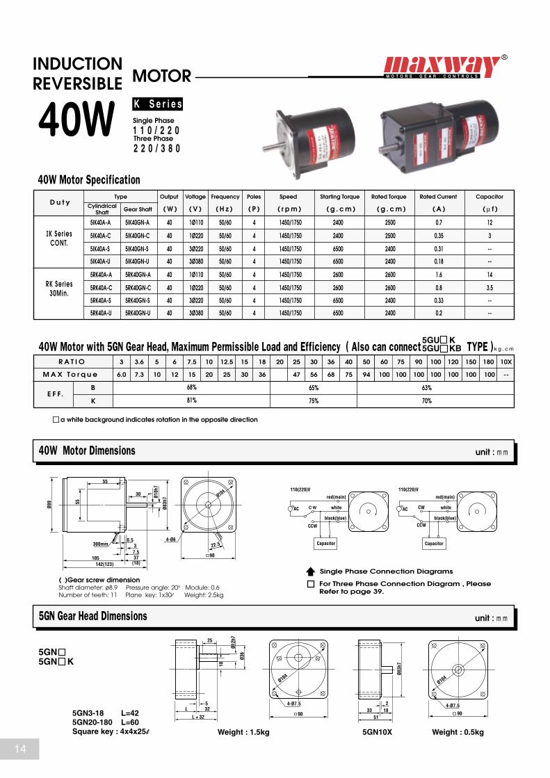
40W Motor Dimensions unit : m m
5GN Gear Head Dimensions unit : m m
5GN5GN K
CylindricalShaft
40W
5IK40A-A 5IK40GN-A 40 1Ø110 4 1450/1750 0.7 1250/60
5IK40A-C 5IK40GN-C 40 4 1450/1750IK Ser iesCONT.
RK Ser ies30Min.
0.35 31Ø220 50/60
5RK40A-A 5RK40GN-A 40 4 1450/1750 2600
2400
2400
1.6 141Ø110 50/60
5RK40A-C 5RK40GN-C 40 4 1450/1750 2600 0.8
2500
2500
5IK40A-S 5IK40GN-S 40 3Ø220 4 1450/1750 0.31 --50/60
5IK40A-U 5IK40GN-U 40 4 1450/1750 0.18 --3Ø380 50/60 6500
6500 2400
2400
5RK40A-S 5RK40GN-S 40 3Ø220 4 1450/1750 0.33 --50/60
5RK40A-U 5RK40GN-U 40 4 1450/1750 0.2 --3Ø380 50/60 6500
6500 2400
2400
2600
2600 3.51Ø220 50/60
R A T I O
M A X T o r q u e
k g . c m
E F F.B
K
3
6.0
3.6
7.3
5
10
6
12
7.5
15
10
20
12.5
25
15
30
18
36
20 25
47
30
56
36
68
40
75
50
94
60
100
75
100
90
100
100
100
120
100
150
100
180
100
10X
--
68%
81%
65%
75%
63%
70%
40W Motor Specification
a white background indicates rotation in the opposite direction
( )Gear screw dimension Shaft diameter: ø8.9 Pressure angle: 20° Module: 0.6 Number of teeth: 11 Plane key: 1x30l Weight: 2.5kg
5GN3-18 L=425GN20-180 L=60 Square key : 4x4x25l Weight : 1.5kg Weight : 0.5kg5GN10X
K S e r i e s
Three Phase
2 2 0 / 3 8 0
Single Phase
1 1 0 / 2 2 0
40W Motor with 5GN Gear Head, Maximum Permissible Load and Efficiency ( Also can connect TYPE )5GU KB5GU K
INDUCTIONREVERSIBLE MOTOR
Single Phase Connection Diagrams
For Three Phase Connection Diagram , PleaseRefer to page 39.
Ø89
105
55
(18)142(123)37
30
7.5
0.53
Ø10h
7
Ø83h
7
1
90
22.5˚
Ø104
4-Ø6
55
300mm
S
Capacitor
AC CW
CCW
red(main)
white
black(blue)
S AC
110(220)V 110(220)V
C W
CCW
red(main)
white
black(blue)
Capacitor
4-Ø7.5
90
Ø104
Ø36
Ø12h
7
L 32
L + 32
5
25
18
Ø83h
7
218
4-Ø7.5
90
Ø104
5133
14

Type Output Voltage Frequency Poles Variable Speed RangeD u t y
Starting Torque Rated Torque Rated Current Capacitor
Gear Shaft ( W ) ( V ) ( H z ) ( P ) ( r p m ) ( g . c m ) ( g . c m ) ( A ) ( µ f )
40W Variable Speed Motor Dimensions unit : m m
5GN Gear Head Dimensions unit : m m
5GN5GN K
CylindricalShaft
40W
5IK40RA-A 5IK40RGN-A 40 1Ø110 4 90/1400/1700 1.5 1250/60
5IK40RA-C 5IK40RGN-C 40 4 90/1400/1700IK Ser iesCONT.
RK Ser ies
30Min.
0.8 31Ø220 50/60
5RK40RA-A 5RK40RGN-A 40 4 90/1400/1700 2400
2300
2300
0.9 141Ø110 50/60
5RK40RA-C 5RK40RGN-C 40 4 90/1400/1700 2400 0.45
600~2500
600~2500
1000~2500
1000~2500 3.51Ø220 50/60
R A T I O
M A X T o r q u e
k g . c m
E F F.B
K
3
6.0
3.6
7.3
5
10
6
12
7.5
15
10
20
12.5
25
15
30
18
36
20 25
47
30
56
36
68
40
75
50
94
60
100
75
100
90
100
100
100
120
100
150
100
180
100
10X
--
68%
81%
65%
75%
63%
70%
40W Motor and Speed Controller Specification
a white background indicates rotation in the opposite direction
K S e r i e sSingle Phase 1 1 0 / 2 2 0
( )Gear screw dimension Shaft diameter: ø8.9 Pressure angle: 20° Module: 0.6Number of teeth: 11 Plane key: 1x30l Weight: 2.5kg
5GN3-18 L=425GN20-180 L=60Square key : 4x4x25l Weight : 1.5kg Weight : 0.5kg5GN10X
40W Motor with 5GN Gear Head, Maximum Permissible Load and Efficiency ( Also Can Connect TYPE )5GU KB5GU K
INDUCTIONREVERSIBLE VARIABLE SPEED MOTOR
Ø89
Ø47
10511
55
(18)116153(134)
37
30
7.53
0.5
Ø10h
7
Ø83h
7
1
90
22.5˚
Ø104
4-Ø6
55
300mm
300mm
4-Ø7.5
90
Ø104
Ø36
Ø12h
7
L 32
L + 32
5
25
18
Ø83h
7
218
4-Ø7.5
90
Ø104
5133
To Choose a Controller , Please Refer to Page 36.
For Controller's Circuit Diagram , Please Refer to Page 38.
15
Type Output Voltage Frequency Poles SpeedD u t y
Starting Torque Rated Torque Rated Current Capacitor
Gear Shaft ( W ) ( V ) ( H z ) ( P ) ( r p m ) ( g . c m ) ( g . c m ) ( A ) ( µ f )
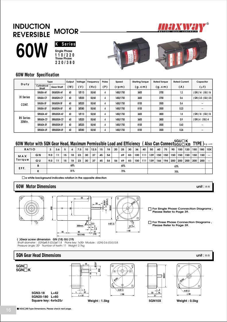
60W Motor Dimensions unit : m m
5GN Gear Head Dimensions unit : m m
5GN5GN K
CylindricalShaft
60W
5IK60A-AF 5IK60GN-AF 60 1Ø110 4 1450/1750 1.2 ( GN ) 14 ( GU ) 16
( GN ) 3.5 ( GU ) 3.5
( GN ) 16 ( GU ) 16
( GN ) 4 ( GU ) 4
50/60
5IK60A-CF 5IK60GN-CF 60 4 1450/1750IK Ser ies
CONT.
RK Ser ies30Min.
0.61Ø220 50/60
5RK60A-AF 5RK60GN-AF 60 4 1450/1750 3600
3600
3600
1.81Ø110 50/60
5RK60A-CF 5RK60GN-CF 60 4 1450/1750 3600 0.9
3700
3700
5IK60A-SF 5IK60GN-SF 60 3Ø220 4 1450/1750 0.4 --50/60
5IK60A-UF 5IK60GN-UF 60 4 1450/1750 0.23 --3Ø380 50/60 8100
8100 3500
3500
5RK60A-SF 5RK60GN-SF 60 3Ø220 4 1450/1750 0.43 --50/60
5RK60A-UF 5RK60GN-UF 60 4 1450/1750 0.26 --3Ø380 50/60 8100
8100 3500
3500
3800
38001Ø220 50/60
R A T I O
M A X T o r q u e
k g . c m
E F F.B
K
G N
G U
3
9.0
3.6
11
5
15
6
18
7.5
23
10
30
12.5
37
15
45
18
54
20 25
69
30
83
36
100
40
111
50
139
60
150
75
150
90
150
100
150
120
150
150
150
180
150
10X
--
68%
81%
65%
75%
63%
70%
60W Motor Specification
a white background indicates rotation in the opposite direction
9.0 11 15 18 23 30 37 45 54 69 83 100 111 139 166 194 200 200 200 200 200 --56
( )Gear screw dimension GN (18) GU (19) Shaft diameter : (GN)ø8.9 (GU)ø11.8 Plane key: 1x30l Module : (GN) 0.6 (GU) 0.8 Pressure angle: 20° Number of teeth: 11 Weight: 2.7kg
5GN3-18 L=425GN20-180 L=60Square key: 4x4x25l Weight : 1.5kg Weight : 0.5kg5GN10X
For Single Phase Connection Diagrams ,Please Refer to Page 39.
For Three Phase Connection Diagrams ,Please Refer to Page 39.
K S e r i e s
Three Phase
2 2 0 / 3 8 0
Single Phase
1 1 0 / 2 2 0
60W Motor with 5GN Gear Head, Maximum Permissible Load and Efficiency ( Also Can Connect TYPE )5GU KB5GU K
INDUCTIONREVERSIBLE MOTOR
Ø90
55
8545
55
(19)167(149)37
30
7.53
0.5
Ø10h
7(Ø
12h7
)
Ø83h
7
1
90
22.5˚
Ø104
4-Ø7.5300mm
4-Ø7.5
90
Ø104
Ø36
Ø12h
7
L 32
L + 32
5
25
18
Ø83h
7
218
4-Ø7.5
90
Ø104
5133
5GU KB Type Dimensions, Please check next page.16

Type Output Voltage Frequency Poles Variable SpeedRangeD u t y
Starting Torque Rated Torque Rated Current Capacitor
Gear Shaft ( W ) ( V ) ( H z ) ( P ) ( r p m ) ( g . c m ) ( g . c m ) ( A ) ( µ f )
60W Variable Speed Motor Dimensions unit : m m
5GN Gear Head Dimensions unit : m m
5GN5GN K
CylindricalShaft
60W
5IK60RA-AF 5IK60RGN-AF 60 1Ø110 4 90/1400/1700 2.450/60
5IK60RA-CF 5IK60RGN-CF 60 4 90/1450/1700IK Ser ies
CONT.
RK Ser ies30Min.
1.21Ø220 50/60
5RK60RA-AF 5RK60RGN-AF 60 4 90/1400/1700 4700
4200
4200
1.51Ø110 50/60
5RK60RA-CF 5RK60RGN-CF 60 4 90/1400/1700 4700 0.8
1200~3700
1200~3700
1200~3700
1200~37001Ø220 50/60
R A T I O
M A X T o r q u e
k g . c m
E F F.B
K
G N
G U
3
9.0
3.6
11
5
15
6
18
7.5
23
10
30
12.5
37
15
45
18
54
20 25
69
30
83
36
100
40
111
50
139
60
150
75
150
90
150
100
150
120
150
150
150
180
150
10X
--
68%
81%
65%
75%
63%
70%
60W Motor and Speed Controller Specification
a white background indicates rotation in the opposite direction
K S e r i e sSingle Phase 1 1 0 / 2 2 0
9.0 11 15 18 23 30 37 45 54 69 83 100 111 139 166 194 200 200 200 200 200 --56
( GN ) 14 ( GU ) 16
( GN ) 3.5 ( GU ) 3.5
( GN ) 16 ( GU ) 16
( GN ) 4 ( GU ) 4
5GN3-18 L=425GN20-180 L=60Square key : 4x4x25l Weight : 1.5kg Weight : 0.5kg5GN10X
To Choose a Controller , Please Refer to Page 36.
For Controller's Circuit Diagram , Please Refer to Page 38.
( )Gear screw dimension GN (18) GU (19) Shaft diameter : (GN)ø8.9 (GU)ø11.8 Plane key: 1x30l Module : (GN) 0.6 (GU) 0.8 Pressure angle: 20° Number of teeth: 11 Weight: 2.7kg
60W Motor with 5GN Gear Head, Maximum Permissible Load and Efficiency ( Also can connect TYPE )5GU KB5GU K
INDUCTIONREVERSIBLE VARIABLE SPEED MOTOR
Ø90
9545
55
(19)177(159)37
30
7.53
0.5
Ø10h
7(Ø
12h7
)Ø8
3h7
1
90
22.5˚
Ø104
4-Ø7.5
55
300mm
4-Ø7.5
90
Ø104
Ø36
Ø12h
7
L 32
L + 32
5
25
18
Ø83h
7
218
4-Ø7.5
90
Ø104
5133
5GU KB Type Dimensions, Please check next page.
17

Type Output Voltage Frequency Poles SpeedD u t y
Starting Torque Rated Torque Rated Current Capacitor
Gear Shaft ( W ) ( V ) ( H z ) ( P ) ( r p m ) ( g . c m ) ( g . c m ) ( A ) ( µ f )
90W Motor Dimensions unit : m m
5GU KB Gear Head Dimensions unit : m m
5GU KB
CylindricalShaft
90W
5IK90A-AF 5IK90GU-AF 90 1Ø110 4 1450/1750 1.7 2550/60
5IK90A-CF 5IK90GU-CF 90 4 1450/1750IK Ser ies
CONT.
RK Ser ies
30Min.
0.8 61Ø220 50/60
5RK90A-AF 5RK90GU-AF 90 4 1450/1750 4500
4800
4800
2.8 251Ø110 50/60
5RK90A-CF 5RK90GU-CF 90 4 1450/1750 4500 1.4
5700
5700
5IK90A-SF 5IK90GU-SF 90 3Ø220 4 1450/1750 0.55 --50/60
5IK90A-UF 5IK90GU-UF 90 4 1450/1750 0.32 --3Ø380 50/60 12000
12000 5500
5500
5RK90A-SF 5RK90GU-SF 90 3Ø220 4 1450/1750 0.6 --50/60
5RK90A-UF 5RK90GU-UF 90 4 1450/1750 0.36 --3Ø380 50/60 12000
12000 5500
5500
5500
5500 61Ø220 50/60
R A T I O
M A X T o r q u e
k g . c m
E F F.B
K
3
13
3.6
15
5
21
6
26
7.5
32
10
40
12.5
50
15
60
18
72
20 25
93
30
111
36
134
40
148
50
185
60
200
75
200
90
200
100
200
120
200
150
200
180
200
10X
--
68%
81%
65%
75%
63%
70%
90W Motor Specification
90W Motor with Gear Head, Maximum Permissible Load and Efficiency
a white background indicates rotation in the opposite direction
74
5GU KB5GU K
( )Gear screw dimension Shaft diameter: ø11.8 Pressure angle: 20° Module: 0.8 Number of teeth: 11 Plane key: 1x30l Weight: 3.2kg
KB 3-18 L=58KB 20-180 L=60Square key :5x5x25l Weight : 1.5kg Weight : 0.6kg5GU10XK
For Single Phase Connection Diagrams , Please Refer to Page 39.
For Three Phase Connection Diagrams , Please Refer to Page 39.
K S e r i e s
Three Phase
2 2 0 / 3 8 0
Single Phase
1 1 0 / 2 2 0
INDUCTIONREVERSIBLE MOTOR
Ø90
55
10045
55
(19)182(164)37
30
7.53
(Ø12
h7)
Ø83h
7
1
90
22.5˚
Ø104
4-Ø7.5300mm
4-Ø7.5
90
Ø104
Ø36
Ø15h
7
L 32
L + 32
5
25
18
Ø83h
7
219
4-Ø7.5
90
Ø104
5233
5GU K Type Dimensions, Please check next page.18

Type Output Voltage Frequency Poles Variable SpeedRangeD u t y
Starting Torque Rated Torque Rated Current Capacitor
Gear Shaft ( W ) ( V ) ( H z ) ( P ) ( r p m ) ( g . c m ) ( g . c m ) ( A ) ( µ f )
90W Variable Speed Motor Dimensions unit : m m
5GU KB Gear Head Dimensions unit : m m
CylindricalShaft
90W
5IK90RA-AF 5IK90RGU-AF 90 1Ø110 4 90/1400/1700 2.9 2550/60
5IK90RA-CF 5IK90RGU-CF 90 4 90/1400/1700IK Ser iesCONT.
RK Ser ies30Min.
1.5 61Ø220 50/60
5RK90RA-AF 5RK90RGU-AF 90 4 90/1400/1700 5800
5500
5500
2.0 251Ø110 50/60
5RK90RA-CF 5RK90RGU-CF 90 4 90/1400/1700 5800 1.0
2500~5500
2500~5500
2500~5500
2500~5500 61Ø220 50/60
R A T I O
M A X T o r q u e
k g . c m
E F F.B
K
3
13
3.6
15
5
21
6
26
7.5
32
10
40
12.5
50
15
60
18
72
20 25
93
30
111
36
134
40
148
50
185
60
200
75
200
90
200
100
200
120
200
150
200
180
200
10X
--
68%
81%
65%
75%
63%
70%
90W Motor and Speed Controller Specification
90W Motor with Gear Head, Maximum Permissible Load and Efficiency
a white background indicates rotation in the opposite direction
K S e r i e sSingle Phase 1 1 0 / 2 2 0
74
5GU KB5GU K
( )Gear screw dimension Shaft diameter: ø11.8 Pressure angle: 20° Module: 0.8 Number of teeth: 11 Plane key: 1x30l Weight: 3.2kg
KB3-18 L=58KB20-180 L=60Square key 5x5x25l Weight : 1.5kg Weight : 0.6kgKB10X
To Choose a Controller , Please Refer to Page 36.
For Controller's Circuit Diagram , Please Refer to Page 38.
5GU KB
INDUCTIONREVERSIBLE VARIABLE SPEED MOTOR
4-Ø7.5
90
Ø104
Ø36
Ø15h
7
L 32
L + 32
5
25
18
Ø90
11045
55
(19)192(174)37
30
7.53
0.5
Ø12h
7
Ø83h
7
1
90
22.5˚
Ø104
4-Ø7.5
55
300mm
Ø83h
7
219
4-Ø7.5
90
Ø104
5233
5GU K Type Dimensions, Please check next page. 19

Type Output Voltage Frequency Poles SpeedD u t y
Starting Torque Rated Torque Rated Current Capacitor
CylindricalShaft Gear Shaft ( W ) ( V ) ( H z ) ( P ) ( r p m ) ( g . c m ) ( g . c m ) ( A ) ( µ f )
120W Motor Dimensions unit : m m
5GU K Gear Head Dimensions unit : m m
5GU K
120W150W
5IK120A-AF 5IK120GU-AF 120 1Ø110 4 1450/1750 3.0 3050/60
5IK120A-CF 5IK120GU-CF 120 4 1450/1750IK Ser iesCONT.
RK Ser ies30Min.
1.5 81Ø220 50/60 5200
5200 6300
6300
5IK150A-SF 5IK150GU-SF 150 3Ø220 4 1450/1750 0.9 --50/60
5IK150A-UF 5IK150GU-UF 150 4 1450/1750 0.55 --3Ø380 50/60 13500
13500 7300
7300
R A T I O
M A X T o r q u e
k g . c m
E F F.B
K
3
13
3.6
21.6
5
30
6
36
7.5
45
10
60
12.5
75
15
90
18
108
20 25
150
30
180
36
216
40
240
50
250
60
250
75
250
90
250
100
250
120
250
150
250
180
250
10X
--
68%
81%
65%
75%
63%
70%
120W & 150W Motor Specification
120W Motor with Gear Head, Maximum Permissible Load and Efficiency
a white background indicates rotation in the opposite direction
120
5GU KB5GU K
( )Gear screw dimension Shaft diameter: ø11.8 Pressure angle: 20° Module: 0.8 Number of teeth: 11 Plane key: 1x30l Weight: 3.2kg
Square key : 5x5x25l
Weight : 1.5kg Weight : 0.6kg5GU10XK
For Single Phase Connection Diagrams , Please Refer to Page 39.
For Three Phase Connection Diagrams , Please Refer to Page 39.
K S e r i e s
Three Phase
2 2 0 / 3 8 0
Single Phase
1 1 0 / 2 2 0
5GU KB TYPE 5GU K TYPE
5GU KB Type Dimensions, please check previous page.
INDUCTION MOTOR
Ø90
55
10045
55
(19)182(164)37
30
7.53
0.5
Ø12h
7
Ø83h
7
1
90
22.5˚
Ø104
4-Ø7.5300mm
4-Ø7
4-Ø8.5
Ø104
Ø34
6090110
130
Ø15h
7
65102
3660
1012
18
8 45
25
Ø83h
7
2
194-Ø7
90
Ø104
52
33
20

Type Output Voltage Frequency Poles Variable SpeedRangeD u t y
Starting Torque Rated Torque Rated Current Capacitor
CylindricalShaft Gear Shaft ( W ) ( V ) ( H z ) ( P ) ( r p m ) ( g . c m ) ( g . c m ) ( A ) ( µ f )
120W Variable Speed Motor Dimensions unit : m m
5GU K Gear Head Dimensions unit : m m
5GU K
INDUCTION VARIABLE SPEED MOTOR
120W
5IK120RA-AF 5IK120RGU-AF 120 1Ø110 4 90/1400/1700 4 2550/60
5IK120RA-CF 5IK120RGU-CF 120 4 90/1400/1700IK Ser iesCONT.
RK Ser ies
30Min.
2 81Ø220 50/60 6500
6500 2500~6500
2500~6500
R A T I O
M A X T o r q u e
k g . c m
E F F.B
K
3
13
3.6
21.6
5
30
6
36
7.5
45
10
60
12.5
75
15
90
18
108
20 25
150
30
180
36
216
40
240
50
250
60
250
75
250
90
250
100
250
120
250
150
250
180
250
10X
--
68%
81%
65%
75%
63%
70%
120W Motor and Speed Controller Specification
120W Motor with Gear Head, Maximum Permissible Load and Efficiency
a white background indicates rotation in the opposite direction
K S e r i e sSingle Phase 1 1 0 / 2 2 0
120
( )Gear screw dimension Shaft diameter: ø11.8 Pressure angle: 20° Module: 0.8Number of teeth: 11 Plane key: 1x30l Weight: 3.2kg
Square key 5x5x25l Weight : 1.5kg Weight : 0.6kg5GU10XK
To Choose a Controller , Please Refer to Page 36.
For Controller's Circuit Diagram , Please Refer to Page 38.
5GU KB Type Dimensions, please check previous page.
5GU K5GU KB
4-Ø7
4-Ø8.5
Ø104
Ø34
6090110
130
Ø15h
7
65102
37 3660
1012
18
8 45
25
Ø90
55
11045
55
(19)192(174)37
30
7.53
0.5
Ø12h
7
Ø83h
7
1
90
22.5˚
Ø104
4-Ø7.5300mm
Ø83h
7
219
4-Ø7
90
Ø104
5233
21

Type Output Voltage Frequency Poles SpeedD u t y
Starting Torque Rated Torque Rated Current Capacitor
Gear Shaft ( W ) ( V ) ( H z ) ( P ) ( r p m ) ( g . c m ) ( g . c m ) ( A ) ( µ f )
unit : m m
unit : m m
CylindricalShaft
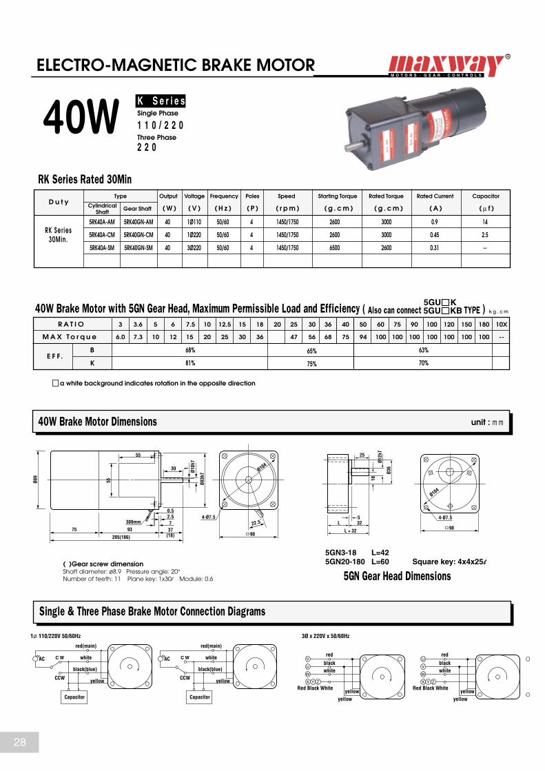
ELECTRO-MAGNETIC BRAKE MOTOR
6 W
RK Ser ies
30Min.
2RK6A-AM 2RK6GN-AM 6 4 1450/1750 400 0.3 2.51Ø110 50/60
2RK6A-CM 2RK6GN-CM 6 4 1450/1750 400 0.2
400
400 0.81Ø220 50/60
R A T I O
M A X T o r q u e
k g . c m
E F F.B
K
3
0.9
3.6
1.0
5
1.5
6
1.8
7.5
2.3
10
3.0
12.5
3.8
15
4.5
18
5.4
20 25
7.0
30
8.3
36
10
40
11
50
14
60
16
75
19
90
23
100
25
120
25
150
25
180
25
10X
--
68%
81%
65%
75%
63%
70%
RK Series Rated 30Min
6W Barake Motor with 2GN Gear Head, Maximum Permissible Load and Efficiency
a white background indicates rotation in the opposite direction
K S e r i e sSingle Phase 1 1 0 / 2 2 0
( )Gear screw dimension Shaft diameter: ø5.5 Pressure angle: 20° Number of teeth: 8 Plane key: 1x10l Module: 0.5
2GN3-18 L=322GN20-180 L=42
2GN Gear Head Dimensions
6W Brake Motor Dimensions
Single Phase Brake Motor Connection Diagrams
Plane key 1x12l
4-Ø5.5
60
Ø70
Ø18
Ø8h7
L 32
L + 32
5
12 110
Capacitor
S AC
110(220)V
C W
CCW
red(main)
white
yellow yellow
black(blue)
Capacitor
S AC
110(220)V
C W
CCW
red(main)
white
black(blue)
Ø59
6851(13)143
(132)
24
6.5
2.5
Ø6h7
Ø54h
7
60
22.5˚
Ø70
300mm
4-Ø5.5
0.5
22

Type Output Voltage Frequency Poles Variable SpeedRangeD u t y
Starting Torque Rated Torque Rated Current Capacitor
Gear Shaft ( W ) ( V ) ( H z ) ( P ) ( r p m ) ( g . c m ) ( g . c m ) ( A ) ( µ f )
6W Variable Speed Motor with Brake Dimensions unit : m m
CylindricalShaft
VARIABLE SPEED WITH ELECTRO-MAGNETIC BRAKE MOTOR
6 W
RK Ser ies
30Min.
2RK6RA-AM 2RK6RGN-AM 6 4 90/1400/1700 330 0.3 2.51Ø110 50/60
2RK6RA-CM 2RK6RGN-CM 6 4 90/1400/1700 330 0.15
250~460
250~460 0.81Ø220 50/60
R A T I O
M A X T o r q u e
k g . c m
E F F.B
K
3
0.9
3.6
1.0
5
1.5
6
1.8
7.5
2.3
10
3.0
12.5
3.8
15
4.5
18
5.4
20 25
7.0
30
8.3
36
10
40
11
50
14
60
16
75
19
90
23
100
25
120
25
150
25
180
25
10X
--
68%
81%
65%
75%
63%
70%
RK Series Rated 30Min
6W Brake Motor with 2GN Gear Head, Maximum Permissible Load and Efficiency
a white background indicates rotation in the opposite direction
K S e r i e sSingle Phase 1 1 0 / 2 2 0
2GN Gear Head Dimensions
2GN2GN K
( )Gear screw dimension Shaft diameter: ø6.6 Pressure angle: 20°Number of teeth: 10 Plane key: 1x10l Module: 0.5
2GN3-18 L=322GN20-180 L=42Plane Key 1x12l
To Choose a Controller , Please Refer to Page 36.
For Controller's Circuit Diagram , Please Refer to Page 38.
Ø59
6851(13)143
(132)
24
6.5
2.5
Ø6h7
Ø54h
7
60
22.5˚
Ø70
300mm
4-Ø5.5
0.5
4-Ø5.5
60
Ø70
Ø18
Ø8h7
L 32
L + 32
5
12 110
Ø54h
7
2
144-Ø5.5
60
Ø70
40
26
2GN10X23

Type Output Voltage Frequency Poles SpeedD u t y
Starting Torque Rated Torque Rated Current Capacitor
Gear Shaft ( W ) ( V ) ( H z ) ( P ) ( r p m ) ( g . c m ) ( g . c m ) ( A ) ( µ f )
15W Brake Motor Dimensions unit : m m
Single Phase Brake Motor Connection Diagrams unit : m m
CylindricalShaft
ELECTRO-MAGNETIC BRAKE MOTOR
1 5 W
R A T I O
M A X T o r q u e
k g . c m
E F F.B
K
3
2.2
3.6
2.6
5
3.7
6
4.4
7.5
5.5
10
7.2
12.5
9.1
15
11
18
13
20 25
17
30
21
36
24
40
29
50
34
60
41
75
47
90
50
100
50
120
50
150
50
180
50
10X
--
68%
81%
65%
75%
63%
70%
RK Series Rated 30Min
15W Barake Motor with 3GN Gear Head, Maximum Permissible Load and Efficiency
a white background indicates rotation in the opposite direction
K S e r i e sSingle Phase 1 1 0 / 2 2 0
RK Ser ies30Min.
3RK15A-AM 3RK15GN-AM 15 4 1450/1750 850 0.45 3.51Ø110 50/60
3RK15A-CM 3RK15GN-CM 15 4 1450/1750 850 0.25
1000
1000 1.21Ø220 50/60
( )Gear screw dimension Shaft diameter: ø6.6 Pressure angle: 20° Number of teeth: 10 Plane key: 1x10l module: 0.5
3GN3-18 L=323GN20-180 L=42
3GN Gear Head DimensionsSquare key: 4x4x25l
Capacitor
S AC
110(220)V
C W
CCW
red(main)
white
yellow yellow
black(blue)
Capacitor
S AC
110(220)V
C W
CCW
red(main)
white
black(blue)
4-Ø6
70
Ø82
Ø30
Ø10h
7
L 32
L + 32
5
25
15Ø69
7257 32(13)161
(142)
72.5
0.5
Ø6h7
Ø64h
7
70
22.5˚
Ø82
4-Ø6300mm
24

Type Output Voltage Frequency Poles Variable SpeedRangeD u t y
Starting Torque Rated Torque Rated Current Capacitor
Gear Shaft ( W ) ( V ) ( H z ) ( P ) ( r p m ) ( g . c m ) ( g . c m ) ( A ) ( µ f )
15W Variable Speed Motor with Brake Dimensions unit : m m
CylindricalShaft
1 5 W
RK Ser ies30Min.
3RK15RA-AM 3RK15RGN-AM 15 4 90/1400/1700 550 0.5 3.51Ø110 50/60
3RK15RA-CM 3RK15RGN-CM 15 4 90/1400/1700 550 0.25
300~660
300~660 1.21Ø220 50/60
R A T I O
M A X T o r q u e
k g . c m
E F F.B
K
3
2.2
3.6
2.6
5
3.7
6
4.4
7.5
5.5
10
7.2
12.5
9.1
15
11
18
13
20 25
17
30
21
36
24
40
29
50
34
60
41
75
47
90
50
100
50
120
50
150
50
180
50
10X
--
68%
81%
65%
75%
63%
70%
RK Series Rated 30Min
15W Brake Motor with 3GN Gear Head, Maximum Permissible Load and Efficiency
a white background indicates rotation in the opposite direction
K S e r i e sSingle Phase 1 1 0 / 2 2 0
3GN Gear Head Dimensions
3GN3GN K
3GN10X
( )Gear screw dimension Shaft diameter: ø6.6 Pressure angle: 20°Number of teeth: 10 Planekey: 1x10l Module: 0.5
3GN3-18 L=32Square key 4x4x20l
3GN20-180 L=45Square key 4x4x25l
To Choose a Controller , Please Refer to Page 36.
For Controller's Circuit Diagram , Please Refer to Page 38.
VARIABLE SPEED WITH ELECTRO-MAGNETIC BRAKE MOTOR
Ø69
7257 32(13)161
(142)
72.5
0.5
Ø6h7
Ø64h
7
70
22.5˚
Ø82
4-Ø6300mm
4-Ø6
70
Ø82
Ø30
Ø10h
7
L 32
L + 32
5
25
15
Ø64h
7
2
12.54-Ø6
70
Ø82
38.5
26
25

Type Output Voltage Frequency Poles SpeedD u t y
Starting Torque Rated Torque Rated Current Capacitor
Gear Shaft ( W ) ( V ) ( H z ) ( P ) ( r p m ) ( g . c m ) ( g . c m ) ( A ) ( µ f )
25W Brake Motor Dimensions unit : m m
Single & Three Phase Brake Motor Connection Diagrams
CylindricalShaft
25W
R A T I O
M A X T o r q u e
k g . c m
E F F.B
K
3
3.7
3.6
4.4
5
6.1
6
7.3
7.5
9.1
10
12
12.5
15
15
18
18
22 23
20 25
28
30
34
36
44
40
49
50
61
60
67
75
79
90
80
100
80
120
80
150
80
180
80
10X
--
68%
81%
65%
75%
63%
70%
RK Series Rated 30Min
25W Barake Motor with 4GN Gear Head, Maximum Permissible Load and Efficiency
a white background indicates rotation in the opposite direction
K S e r i e sSingle Phase
1 1 0 / 2 2 0Three Phase
2 2 0
RK Ser ies30Min.
4RK25A-AM 4RK25GN-AM 25 4 1450/1750 1500 0.58 81Ø110 50/60
4RK25A-CM 4RK25GN-CM 25 4 1450/1750 1500 0.29
4RK25A-SM 4RK25GN-SM 25 3Ø220 4 1450/1750 0.2 --50/60 5000 1500
1500
1500 21Ø220 50/60
( )Gear screw dimension Shaft diameter: ø7.9 Pressure angle: 20° Number of teeth: 9 Plane key: 1x25l Module: 0.6
4GN3-18 L=324GN20-180 L=45
4GN Gear Head DimensionsSquare key: 4x4x25l
ELECTRO-MAGNETIC BRAKE MOTOR
Capacitor
S AC
1ø 110/220V 50/60Hz
C W
CCW
red(main)
white
yellow yellow
black(blue)
Capacitor
S AC C W
CCW
red(main)
white
black(blue)
V
U
W
X Y Z
3Ø x 220 x 50/60Hz
red
Red Black Whiteyellow
yellow
blackwhite
U
V
W
X Y Z
red
Red Black Whiteyellow
yellow
blackwhite
4-Ø6
80
Ø94
Ø32
Ø10h
7
L 32
L + 32
5
25
15
4-Ø6
Ø79
174.5(155.5)
48
77.5 32(13)
72.50.5
65
Ø73h
7Ø8h7
80
22.5˚
Ø94
300mm
45
26

Type Output Voltage Frequency Poles Variable SpeedRangeD u t y
Starting Torque Rated Torque Rated Current Capacitor
Gear Shaft ( W ) ( V ) ( H z ) ( P ) ( r p m ) ( g . c m ) ( g . c m ) ( A ) ( µ f )
unit : m m25W Variable Speed Motor with Brake Dimensions
CylindricalShaft
25W
RK Ser ies
30Min.
4RK25RA-AM 4RK25RGN-AM 25 4 90/1400/1700 1400 0.9 81Ø110 50/60
4RK25RA-CM 4RK25RGN-CM 25 4 90/1400/1700 1400 0.45
300~1600
300~1600 21Ø220 50/60
R A T I O
M A X T o r q u e
k g . c m
E F F.B
K
3
3.7
3.6
4.4
5
6.1
6
7.3
7.5
9.1
10
12
12.5
15
15
18
18
22 23
20 25
28
30
34
36
44
40
49
50
61
60
67
75
79
90
80
100
80
120
80
150
80
180
80
10X
--
68%
81%
65%
75%
63%
70%
a white background indicates rotation in the opposite direction
K S e r i e sSingle Phase 1 1 0 / 2 2 0
4GN Gear Head Dimensions
4GN4GN K
4GN10X
RK Series Rated 30Min
25W Brake Motor with 2GN Gear Head, Maximum Permissible Load and Efficiency
To Choose a Controller , Please Refer to Page 36.
For Controller's Circuit Diagram , Please Refer to Page 38.
VARIABLE SPEED WITH ELECTRO-MAGNETIC BRAKE MOTOR
( )Gear screw dimension Shaft diameter: ø7.9 Pressure angle: 20°Number of Teeth: 9 Plane Key: 1x25l Module: 0.6
4GN3-18 L=324GN20-180 L=45Square key 4x4x25l
4-Ø6
Ø79
174.5(155.5)
48
77.5 32(13)
72.50.5
65
Ø73h
7Ø8h7
80
22.5˚
Ø94
300mm
45
4-Ø6
80
Ø94
Ø32
Ø10h
7
L 32
L + 32
5
25
15
Ø73h
7
213
4-Ø6
80
Ø94
3926
27
Type Output Voltage Frequency Poles SpeedD u t y
Starting Torque Rated Torque Rated Current Capacitor
Gear Shaft ( W ) ( V ) ( H z ) ( P ) ( r p m ) ( g . c m ) ( g . c m ) ( A ) ( µ f )
unit : m m
Single & Three Phase Brake Motor Connection Diagrams
40W Brake Motor Dimensions
CylindricalShaft
40W
R A T I O
M A X T o r q u e
k g . c m
E F F.B
K
3
6.0
3.6
7.3
5
10
6
12
7.5
15
10
20
12.5
25
15
30
18
36
20 25
47
30
56
36
68
40
75
50
94
60
100
75
100
90
100
100
100
120
100
150
100
180
100
10X
--
68%
81%
65%
75%
63%
70%
RK Series Rated 30Min
a white background indicates rotation in the opposite direction
RK Ser ies30Min.
5RK40A-AM 5RK40GN-AM 40 4 1450/1750 2600 0.9 141Ø110 50/60
5RK40A-CM 5RK40GN-CM 40 4 1450/1750 2600 0.45
5RK40A-SM 5RK40GN-SM 40 3Ø220 4 1450/1750 0.31 --50/60 6500 2600
3000
3000 2.51Ø220 50/60
K S e r i e sSingle Phase
1 1 0 / 2 2 0Three Phase
2 2 0
40W Brake Motor with 5GN Gear Head, Maximum Permissible Load and Efficiency 5GU KB5GU K
ELECTRO-MAGNETIC BRAKE MOTOR
( Also can connect TYPE )
Capacitor
S AC
1ø 110/220V 50/60Hz
C W
CCW
red(main)
white
yellow yellow
black(blue)
Capacitor
S AC C W
CCW
red(main)
white
black(blue)
V
U
W
X Y Z
3Ø x 220V x 50/60Hz
red
Red Black Whiteyellow
yellow
blackwhite
U
V
W
X Y Z
red
Red Black Whiteyellow
yellow
blackwhite
( )Gear screw dimension Shaft diameter: ø8.9 Pressure angle: 20° Number of teeth: 11 Plane key: 1x30l Module: 0.6
Square key: 4x4x25l
5GN3-18 L=425GN20-180 L=60
5GN Gear Head Dimensions
Ø89
55
(18)9375
205(186)37
30
72.50.5
Ø10h
7
Ø83h
7
1
90
22.5˚
Ø104
4-Ø7.5
55
300mm4-Ø7.5
90
Ø104
Ø36
Ø12h
7
L 32
L + 32
5
25
18
28

Type Output Voltage Frequency Poles Variable SpeedRangeD u t y
Starting Torque Rated Torque Rated Current Capacitor
Gear Shaft ( W ) ( V ) ( H z ) ( P ) ( r p m ) ( g . c m ) ( g . c m ) ( A ) ( µ f )
unit : m m40W Variable Speed Motor with Brake Dimensions
CylindricalShaft
40W
RK Ser ies30Min.
5RK40RA-AM 5RK40RGN-AM 40 4 90/1400/1700 2400 1.6 141Ø110 50/60
5RK40RA-CM 5RK40RGN-CM 40 4 90/1400/1700 2400 0.8
1000~2500
1000~2500 2.51Ø220 50/60
R A T I O
M A X T o r q u e
E F F.B
K
3
6.0
3.6
7.3
5
10
6
12
7.5
15
10
20
12.5
25
15
30
18
36
20 25
47
30
56
36
68
40
75
50
94
60
100
75
100
90
100
100
100
120
100
150
100
180
100
10X
--
68%
81%
65%
75%
63%
70%
a white background indicates rotation in the opposite direction
K S e r i e sSingle Phase 1 1 0 / 2 2 0
5GN Gear Head Dimensions
5GN5GN K
5GN10X
To Choose a Controller , Please Refer to Page 36.
For Controller's Circuit Diagram , Please Refer to Page 38.
RK Series Rated 30Min
VARIABLE SPEED WITH ELECTRO-MAGNETIC BRAKE MOTOR
5GN3-18 L=425GN20-180 L=60Square key 4x4x25l
k g . c m40W Brake Motor with 5GN Gear Head, Maximum Permissible Load and Efficiency 5GU KB5GU K
5GU KB5GU K Type Dimensions Please check next page.
( Also can connect TYPE )
( )Gear screw dimension Shaft diameter: ø8.9 Pressure angle: 20°Number of teeth: 11 Plane key: 1x30l Module: 0.6
Ø89
55
(18)9375
205(186)37
30
72.50.5
Ø10h
7
Ø83h
7
1
90
22.5˚
Ø104
4-Ø7.5
55
300mm
4-Ø7.5
90
Ø104
Ø36
Ø12h
7
L 32
L + 32
5
25
18
Ø83h
7
218
4-Ø7.5
90
Ø104
5133
29

Type Output Voltage Frequency Poles SpeedD u t y
Starting Torque Rated Torque Rated Current Capacitor
Gear Shaft ( W ) ( V ) ( H z ) ( P ) ( r p m ) ( g . c m ) ( g . c m ) ( A ) ( µ f )
unit : m m
Single & Three Phase Brake Motor Connection Diagrams
60W Brake Motor Dimensions
CylindricalShaft
60WRK Series Rated 30Min ( It Fit GN Type . GU Type )
RK Ser ies
30Min.
5RK60A-AM 5RK60GN-AM 60 4 1450/1750 3000 1.4 161Ø110 50/60
5RK60A-CM 5RK60GN-CM 60 4 1450/1750 3000 0.7
3800
3800 41Ø220 50/60
5RK60A-SM 5RK60GN-SM 60 4 1450/1750 5000 0.63800 -3Ø220 50/60
R A T I O
M A X T o r q u e
k g . c m
E F F.B
K
G N
G U
3
9.0
3.6
11
5
15
6
18
7.5
23
10
30
12.5
37
15
45
18
54
20 25
69
30
83
36
100
40
111
50
139
60
150
75
150
90
150
100
150
120
150
150
150
180
150
10X
--
68%
81%
65%
75%
63%
70%
a white background indicates rotation in the opposite direction
9.0 11 15 18 23 30 37 45 54 69 83 100 111 139 166 194 200 200 200 200 200 --56
K S e r i e sSingle Phase
1 1 0 / 2 2 0Three Phase
2 2 0
60W Brake Motor with 5GN Gear Head, Maximum Permissible Load and Efficiency 5GU KB5GU K
5GN3-18 L=425GN20-180 L=60
5GN Gear Head Dimensions
( Also can connect TYPE )
Capacitor
S AC
1ø 110/220V 50/60Hz
C W
CCW
red(main)
white
yellow yellow
black(blue)
Capacitor
S AC C W
CCW
red(main)
white
black(blue)
V
U
W
X Y Z
3Ø x 220V x 50/60Hz
red
Red Black Whiteyellow
yellow
blackwhite
U
V
W
X Y Z
red
Red Black Whiteyellow
yellow
blackwhite
Ø89
93
55
75(18)205(186)37
30
72.50.5
Ø10h
7(Ø
12h7
)
Ø83h
7
1
90
22.5˚
Ø104
4-Ø7.5
55
300mm
4-Ø7.5
90
Ø104
Ø36
Ø12h
7
L 32
L + 32
5
25
18
( )Gear screw dimension GN (18) GU (19) Shaft diameter : (GN)ø8.9 (GU)ø11.8 Plane key: 1x30l
Pressure angle: 20° Number of teeth: 11 Module : (GN) 0.6 (GU) 0.8
Square key: 4x4x25l
ELECTRO-MAGNETIC BRAKE MOTOR
30

Type Output Voltage Frequency Poles Variable SpeedRangeDuty
Starting Torque Rated Torque Rated Current Capacitor
Gear Shaft ( W ) ( V ) ( H z ) ( P ) ( r p m ) ( g . c m ) ( g . c m ) ( A ) ( µ f )
unit : m m
5GN Gear Head Dimensions
60W Variable Speed Motor with Brake Dimensions
CylindricalShaft
60WK S e r i e sSingle Phase 1 1 0 / 2 2 0
RK Ser ies
30Min.
5RK60RA-AM 5RK60RGN-AM 60 4 90/1450/1750 3000 1.8 161Ø110 50/60
5RK60RA-CM 5RK60RGN-CM 60 4 90/1450/1750 3000 0.9
1100~3500
1100~3500 41Ø220 50/60
R A T I O
M A X T o r q u e
k g . c m
E F FB
K
G N
G U
3
9.0
3.6
11
5
15
6
18
7.5
23
10
30
12.5
37
15
45
18
54
20 25
69
30
83
36
100
40
111
50
139
60
150
75
150
90
150
100
150
120
150
150
150
180
150
10X
--
68%
81%
65%
75%
63%
70%
a white background indicates rotation in the opposite direction
9.0 11 15 18 23 30 37 45 54 69 83 100 111 139 166 194 200 200 200 200 200 --56
VARIABLE SPEED WITH ELECTRO-MAGNETIC BRAKE MOTOR
RK Series Rated 30Min ( It Fit GN Type . GU Type )
60W Brake Motor with 5GN Gear Head, Maximum Permissible Load and Efficiency 5GU KB5GU K
( )Gear screw dimension GN (18) GU (19) Shaft diameter : (GN)ø8.9 (GU)ø11.8 Plane Key: 1x30l
Pressure angle: 20° Number of teeth: 11 Module : (GN) 0.6 (GU) 0.8
5GN10X5GU KB5GU K Type Dimensions, Please check next page.
5GN3-18 L=425GN20-180 L=60Square key 4 x4 x25l
( Also can connect TYPE )
Ø89
93
55
75(18)205(186)37
30
72.50.5
Ø10h
7(Ø
12h7
)
Ø83h
7
1
90
22.5˚
Ø104
4-Ø7.5
55
300mm
To Choose a Controller , Please Refer to Page 36.
For Controller's Circuit Diagram , Please Refer to Page 38.
5GN5GN K
4-Ø7.5
90
Ø104
Ø36
Ø12h
7
L 32
L + 32
5
25
18
Ø83h
7
218
4-Ø7.5
90
Ø104
5133
31

Type Output Voltage Frequency Poles SpeedDuty
Starting Torque Rated Torque Rated Current Capacitor
Gear Shaft ( W ) ( V ) ( H z ) ( P ) ( r p m ) ( g . c m ) ( g . c m ) ( A ) ( µ f )
unit : m m90W Brake Motor Dimensions
Single & Three Phase Brake Motor Connection Diagrams
CylindricalShaft
90W
R A T I O
M A X T o r q u e
k g . c m
E F F.B
K
3
13
3.6
15
5
21
6
26
7.5
32
10
40
12.5
50
15
60
18
72 74
20 25
93
30
111
36
134
40
148
50
185
60
200
75
200
90
200
100
200
120
200
150
200
180
200
10X
--
68%
81%
65%
75%
63%
70%
RK Series Rated 30Min
a white background indicates rotation in the opposite direction
RK Ser ies
30Min.
5RK90A-AMF 5RK90GU-AMF 90 4 1450/1750 4500 2.0 251Ø110 50/60
5RK90A-CMF 5RK90GU-CMF 90 4 1450/1750 4500 1.0
5RK90A-SMF 5RK90GU-SMF 90 3Ø220 4 1450/1750 0.8 --50/60 7000 5700
5700
5700 61Ø220 50/60
( )Gear screw dimension Shaft diameter: ø11.8 Pressure angle: 20°Number of teeth: 11 Plane key: 1x30l Module: 0.8
K S e r i e sSingle Phase
1 1 0 / 2 2 0Three Phase
2 2 0
5GU KB Gear Head Dimensions
90W Brake Motor with Gear Head, Maximum Permissible Load and Efficiency5GU KB5GU K
5GU KB Type5GU K Type
KB 3-18 L=58KB20-180 L=60 Square key : 5x5x25l
ELECTRO-MAGNETIC BRAKE MOTOR
Capacitor
S AC C W
CCW
red(main)
white
yellow yellow
black(blue)
Capacitor
S AC C W
CCW
red(main)
white
black(blue)
V
U
W
X Y Z
3Ø x 220V x 50/60Hz
red
Red Black Whiteyellow
yellow
blackwhite
U
V
W
X Y Z
red
Red Black Whiteyellow
yellow
blackwhite
Ø89
11175
55
(19)223(205)
37
30
72.5
0.5
(Ø12
h7)
Ø83h
7
1
90
22.5˚
Ø104
4-Ø7.5
55
300mm4-Ø7.5
90
Ø104
Ø36
Ø15h
7
L 32
L + 32
5
25
18
1Ø x 110V/220V x 50/60Hz
5GU K Type Dimensions, please check next page.
32

Type Output Voltage Frequency Poles Variable SpeedRangeDuty
Starting Torque Rated Torque Rated Current Capacitor
Gear Shaft ( W ) ( V ) ( H z ) ( P ) ( r p m ) ( g . c m ) ( g . c m ) ( A ) ( µ f )
90W Variable Speed Motor Dimensions unit : m m
5GU KB Gear Head Dimensions
CylindricalShaft
90W
R A T I O
M A X T o r q u e
k g . c m
E F F.B
K
3
13
3.6
15
5
21
6
26
7.5
32
10
40
12.5
50
15
60
18
72 74
20 25
93
30
111
36
134
40
148
50
185
60
200
75
200
90
200
100
200
120
200
150
200
180
200
10X
--
68%
81%
65%
75%
63%
70%
a white background indicates rotation in the opposite direction
K S e r i e sSingle Phase 1 1 0 / 2 2 0
RK Ser ies
30Min.
5RK90A-AMF 5RK90GU-AMF 90 4 90/1400/1700 3600 2.0 251Ø110 50/60
5RK90A-CMF 5RK90GU-CMF 90 4 90/1400/1700 3600 1.0
1200~4000
1200~4000 61Ø220 50/60
RK Series Rated 30Min 5GU KB Type5GU K Type
90W Brake Motor with Gear Head, Maximum Permissible Load and Efficiency5GU KB5GU K
( )Gear screw dimension Shaft diameter: ø11.8 Pressure angle: 20°Number of teeth: 11 Plane key: 1x30l Module: 0.8
5GU K Type Dimensions, Please check next page.
5GU KB
KB3-18 L=58KB20-180 L=60Square key 5x5x25l
4-Ø7.5
90
Ø104
Ø36
Ø15h
7
L 32
L + 32
5
25
18
Ø83h
7
219
4-Ø7.5
90
Ø104
5233
Ø89
11175
55
(19)223(205)
37
30
72.5
0.5
(Ø12
h7)
Ø83h
7
1
90
22.5˚
Ø104
4-Ø7.5
55
300mm
VARIABLE SPEED WITH ELECTRO-MAGNETIC BRAKE MOTOR
To Choose a Controller , Please Refer to Page 36.
For Controller's Circuit Diagram , Please Refer to Page 38.
KB10X33

Type Output Voltage Frequency Poles SpeedDuty
Starting Torque Rated Torque Rated Current Capacitor
Gear Shaft ( W ) ( V ) ( H z ) ( P ) ( r p m ) ( g . c m ) ( g . c m ) ( A ) ( µ f )
unit : m m120W Brake Motor Dimensions
Single & Three Phase Brake Motor Connection Diagrams
CylindricalShaft
R A T I O
M A X T o r q u e
k g . c m
E F F.B
K
3
13
3.6
21.6
5
30
6
36
7.5
45
10
60
12.5
75
15
90
18
108 120
20 25
150
30
180
36
216
40
240
50
250
60
250
75
250
90
250
100
250
120
250
150
250
180
250
10X
--
68%
81%
65%
75%
63%
70%
a white background indicates rotation in the opposite direction
RK Ser ies30Min.
5RK120A-AM 5RK120GU-AM 120 4 1450/1750 6300 4 251Ø110 50/60
5RK120A-CM 5RK120GU-CM 120 4 1450/1750 6300 2
5RK150A-SM 5RK150GU-SM 150 3Ø220 4 1450/1750 0.9 --50/60 13500 7300
6500
6500 81Ø220 50/60
120W150W
K S e r i e sSingle Phase
1 1 0 / 2 2 0Three Phase
2 2 0
120W Brake Motor with Gear Head, Maximum Permissible Load and Efficiency5GU KB5GU K
( )Gear screw dimension Shaft diameter: ø11.8 Pressure angle: 20°Number of teeth: 11 Plane key: 1x30l Module: 0.8
Square key : 5x5x25l
5GU K Gear Head Dimensions5GU KB Type Dimensions, please check previous page.
ELECTRO-MAGNETIC BRAKE MOTOR
1Ø x 110V/220V x 50/60Hz
RK Series Rated 30Min
Capacitor
S AC C W
CCW
red(main)
white
yellow yellow
black(blue)
Capacitor
S AC C W
CCW
red(main)
white
black(blue)
V
U
W
X Y Z
3Ø x 220V x 50/60Hz
red
Red Black Whiteyellow
yellow
blackwhite
U
V
W
X Y Z
red
Red Black Whiteyellow
yellow
blackwhite
Ø89
11175
55
(19)223(205)
37
30
72.5
0.5
Ø12h
7
Ø83h
7
1
90
22.5˚
Ø104
4-Ø7.5
55
300mm
4-Ø7
60
36
4-Ø8.5
Ø104
Ø34
6090110
130
Ø15h
7
65102
371012
18
8 45
25
5GU KB Type5GU K Type
34

Type Output Voltage Frequency Poles Variable SpeedRangeD u t y
Starting Torque Rated Torque Rated Current Capacitor
Gear Shaft ( W ) ( V ) ( H z ) ( P ) ( r p m ) ( g . c m ) ( g . c m ) ( A ) ( µ f )
unit : m m
unit : m m
120W Variable Speed Motor with Brake Dimensions
5GU K Gear Head Dimensions
CylindricalShaft
120W
R A T I O
M A X T o r q u e
k g . c m
E F F.B
K
3
13
3.6
21.6
5
30
6
36
7.5
45
10
60
12.5
75
15
90
18
108 120
20 25
150
30
180
36
216
40
240
50
250
60
250
75
250
90
250
100
250
120
250
150
250
180
250
10X
--
68%
81%
65%
75%
63%
70%
a white background indicates rotation in the opposite direction
K S e r i e sSingle Phase 1 1 0 / 2 2 0
RK Ser ies30Min.
5RK120A-RAM 5RK120RGU-AM 120 4 90/1400/1700 6300 4 251Ø110 50/60
5RK120A-RCM 5RK120RGU-CM 120 4 90/1400/1700 6300 2
6500
6500 81Ø220 50/60
( )gear screw dimension Shaft diameter: ø11.8 Pressure angle: 20°Number of teeth: 11 Plane key: 1x30l Module: 0.8
RK Series Rated 30Min
5GU K
Square key 5x5x25l
VARIABLE SPEED WITH ELECTRO-MAGNETIC BRAKE MOTOR
120W Brake Motor with Gear Head, Maximum Permissble Load and Efficiency5GU KB5GU K
5GU10XK
5GU KB Type5GU K Type
Ø89
11175
55
(19)223(205)
37
30
72.5
0.5
Ø12h
7
Ø83h
7
1
90
22.5˚
Ø104
4-Ø7.5
55
300mm
To Choose a Controller , Please Refer to Page 36.
For Controller's Circuit Diagram , Please Refer to Page 38.
5GU KB Type Dimensions, Please check previous page.
4-Ø7
60
36
4-Ø8.5
Ø104
Ø34
6090110
130
Ø15h
7
65102
371012
18
8 45
25
Ø83h
7
219
4-Ø7
90
Ø104
5233
35

US51US52
UN51UN52
SS11SS22
SB31INSB32IN
SD31HRSD32HR
S S 22 E
MODEL FUNCTION VOLTAGE OTHERS : SeparatedU : United
B : BrakeS : Speed ControllerD : Electronic Brake & Speed Controller
11 : 110VAC/1Ø22 : 220VAC/1Ø
I N : Inch OperationHR : High Response E :European Regulation (50HZ)
INDUCTION MOTORVARIABLE SPEED CONTROLLER
Model Codes
Specifications of Speed Controller
US 51/52
UN 51/52
SS 11
SS 22
SD 31 HR
SD 32 HR
SB 31
SB 32
MotorOutput
Voltage FrequencySpeedControlRange
MODELSpeed
Variation( W )( V ) ( H z ) ( r p m )
Allowable Current
( A )
SpeedResponse
ElectronicBrake
SpeedStability
United TypeSpeed
ControllerNumeral Type
SeparateType
SpeedController
SeparateType
SpeedController+Electronic
Brake
WorkingTemperature
ElectronicBrake
Function
90/14000.5 Sec
90/1700Exc550/60 6~120 --5 % -10 ~ + 4 0 C C
110 10
220 10
90/14000.5 Sec
90/1700Exc550/60 6~120 --5 % -10 ~ + 4 0 C C
110 10
220 10
90/14000.5 Sec
90/1700ExcYes550/60 6~120 5 % -10 ~ + 4 0 C C
110 10
220 10
Yes-- -- 0.5 Sec Exc550/60 6~120 -10 ~ + 4 0 C C110 10
220 10
36

US51 US52
UN51 UN52
SS11 SS22 :SD31HR SD32HR:
40
50
70
83
60100
87 2.5
1452
1
3030 90 10
010
0
80
2-Ø4.5
23456
60100
87 2.5
1452
1
3030 9080
2-Ø4.5
23456
(For Induction Motor)
Separate Type unit : m m
Numeral Type unit : m m
Unit Type unit : m m
DIMENSION FIGURE OF VARIABLE SPEED CONTROLLER
Models are available with hidden capacitors
Models are available with hidden capacitors
Separate Variable Speed Controller + Electronic BrakeSeparate Variable Speed Controller
37

CONNECTION DIAGRAM OFVARIABLE SPEED CONTROLLER
SS11SS22
SD31HRSD32HR
Speed Controller& Electronic Brake
Unit Type Speed Controller Separate Type Speed Controller
(For Induction Motor)
US51US52
CW Motor
Power Source
CCW
red
white
black(blue)
Capacitor
1
2
3
4
5
6
RPM
SW
SW2
Small Yellow
Small Yellow
Separate Type
Parts Number Capacity
Above AC250V 5A
Above AC250V 5A
Above AC250V 5A
Above DC 20V 10mA
Above AC250V 5A MY2 . LY2
S P.
SW
SW 2
R
Contact Protect
DP . DT
VR
SWC
RELAY
SW 1 SW 1
RO CO
Resistance For Brake Use
Rum
Rum
4
5 6
12
3
SW1
Motor
PowerSource
SW
VR
SW1
Brake
Brake R
red
white
black
72
6
1
38
5
420K 1/4W
RPM
Small Yellow
Small Yellow
CW
SWCRPM
Motor
PowerSource
SW
SW2
Stop
20K 1/4W
1
2
3
CCW
red
white
black(blue)
Capacitor
AC
AC
2
78
1
6
3
4
5
Small Yellow
Small YellowFeed Back
Feed Back
Run
low Speed
VR
Hi Speed
20K 1/4W
5~10 10W
RO=5~100 Above 1/4WCO=0.4~0.27 F 400W
Capacity Requirements for Related Parts
Capacity Requirements for Related Parts
Feed Back
38

Capacitor
SAC
110(220)V
C W
CCW
red(main)
white
black(blue)
SAC CW
CCW
red(main)
white
black(blue)
110(220)V
Capacitor
red
white
black
C.W.
U
V
W
R
S
T
white
white
white
C.W.
X
Y
Z
U
V
W
R
S
T
red
white
black
C.C.W.
V
U
W
R
S
T
white
white
white
C.C.W.
Y
X
Z
V
U
W
R
S
T
white
white
white
white
C.C.W.
X Y Z
V
U
W
R
S
T
C.W.
white
white
white
white
To Join To Join
X Y Z
U
V
W
R
S
T
WIRING DIAGRAM OFINDUCTION MOTOR
( A ) Three Lines 3 220V 50/60 HZ
Connection-Diagrams Of Single Phase Motor
Connection Diagrams Of Three Phase Motor
( B ) Six Lines 3 220V 50/60 HZ & 3 380V 50/60 HZ
Type Connection : Six Lines 3 220V 50/60 HZ
Type Connection : Six Lines 3 380V 50/60 HZ
39

The Dimensions For 6W Motor & Straight Gear Reducer unit : m m
Dimensions for 2 LB
ELECTRONIC BRAKE
SPECIFICATION : SB TYPE ( SB31-IN . SB32-IN )
T Y P E
S B 3 2 - I N
S B 3 1 - I N
Each motor requires one electronic brake.When switched to run, Motor starts; Switched to stop, Motor stalls.Caution! There is over 200V on each contact of thisterminal, Pay extra attention in wiring.Use quality relays, Switches, etc. For SB32, a switch with capacity over AC 200V/5A is required.Do not revers the motor within 0.5sec after switched to run or stop.Due to the choking-load nature of motor, every ON/OFF action generates sparks, To protect the Contacts, Please connect the CR-circuit (see the wiring-diagram below) as a snubber.
12
3
4
5
6
Voltage ( V ) Phase BrakeLongitude
ResponseTime
AllowableMotor Power ( W )
WorkingTemperature
0.5 Sec 6~120 -10 ~ + 4 0 C C
-10 ~ + 4 0 C C
200
200
110 10
220 10 0.5 Sec 6~120
Single ( 1 )
Single ( 1 )
Relay 2B
AC power supply
3
1
4 5
1 8
6
7
3
2
2
4
5
6
Motor
red
white
black
Capacitor
Stop
Co
Ro
Run
Run
Stop
Ro=5~200 (above1/4W) Co=0.4~0.2 F (above 400 W)
Dimensions for 2 LF
24
60 76 90
10
12Ø14
4082
L1
L2 ±
0.4
6.3
x 9.
5 sl
ot
32
SID
E M
5 P0
8
13
Ø23
Ø70
65
3
4-6.3x9.5 slot
365
10
13
Ø70
L2 ±0.4
38
6076 90
2440
82
L1
SIDE M5 P08
Ø1412
40
50
57
73
2 R K 6 G N - A . C
2 R K 6 R G N - A . C
2 R K 6 G N - A M . C M
M o t o r M o d e l L 1 S i z e
1 5 7 . 5 m m
1 6 8 m m
1 9 7 m m
For Motor 6W
L 2 S i z e
5 6 0 m m
4 6 0 m m
3 6 0 m m
2 6 0 m m
1 6 0 m m
R e d u c e r M o d e l
2 L B ( F ) - 1
2 L B ( F ) - 2
2 L B ( F ) - 3
2 L B ( F ) - 4
2 L B ( F ) - 5
For Reducer -No.2 (60mm)
40

STRAIGHT GEAR REDUCER
D I M E N S I O N
Dimensions for 4 LF Dimensions for 4 LB
4 ( 8 0 m m )
2 ( 6 0 m m )
Vo l t a g e ( V )M o d e l
L BL F
L BL F
B a s i c S p e e d( m m / s e c )
M a x i m u mT h r u s t ( k g )
M a x i m u mDistance ( mm )
A l l o w a b l eL o a d ( k g )
2 0
7 0
110 101220 101
110 101220 101
The Dimensions For 25W Motor & Straight Gear Reducer unit : m m
4 R K 2 5 G N - A . C
4 R K 2 5 R G N - A . C
4 R K 2 5 G N - A M . C M
4 R K 2 5 R G N - A M . C M
M o t o r M o d e l L 1 S i z e
1 8 3 . 5 m m
1 9 3 . 5 m m
2 2 8 . 5 m m
2 3 8 . 5 m m
For Motor 25W
Application Examples
Specifications
L 2 S i z e
5 8 0 m m
4 8 0 m m
3 8 0 m m
2 8 0 m m
1 8 0 m m
R e d u c e r M o d e l
4 L B ( F ) - 1
4 L B ( F ) - 2
4 L B ( F ) - 3
4 L B ( F ) - 4
4 L B ( F ) - 5
For Reducer -No.4(80mm)
4LB 4LF
MODEL CODES
4 L B 45 3
PLATFORM 2
PLATFORM 1
PLATFORM 2 PLATFORM 1
PLATFORM 2
PLATFORM 1DIMENSION
2 : 60 mm4 : 80 mm
BASIC SPEED10mm/sec 20mm/sec25mm/sec 45mm/sec
50mm/sec
MAXIMUMDISTANCE1 : 100mm2 : 200mm3 : 300mm4 : 400mm5 : 500mm
STRAIGHT GEAR REDUCER
MOVEMENT DIRECTION( BASED ON FIXED SEAT )
B : HORIZONTAL F : VERTICAL
10 2025 4550
100 200300
100 200300 400500
10 2025 4550
3
5
30
803.
2
99 120
10
17
Ø20
5355
L1
L2 ±
0.4
8x1
2 sl
ot
44
SID
E M
10x1
.5
19
Ø32
Ø95
89
5
589
10
19
19
Ø95
L2 ±0.4
52.7
80 99 120
3053
99
L1 184
8 12 slot
SIDE M10 1.5
Ø203.2
41

HOLLOW SHAFTWORM GEAR REDUCER
Gear Ratio : 10. 15. 20. 25. 30. 40. 50. 60. 80. 100
0ptions : Multiple Installation Available
FIANGE ADAPTER
I 1 I 2
I 3 I 4
DC MOTOR
AC MOTOR
TPG DISCOWS TYPE : 030#
~ 075#
DOUBLE SHAFT SINGLE SHAFT
MOUNTING BASE
Example
GARBAGE PROCESSINGDRYER
PACKING MACHINERY AUTO FILLING PACKINGMACHINERY
CONVEYOR
42

WM TYPE
0.6KW-2.2KW
SIZE
030
040
050
063
075
HP
1/8HP
1/4HP
1/8HP
1/4HP
1/2HP
1/4HP
1/2HP
1HP
1/2HP
1HP
2HP
1/2HP
1HP
2HP
3HP
RATIO
10
10
-
10
10
-
10
10
-
10
10
-
-
10
10
20
20
-
20
20
-
20
20
-
20
20
-
20
20
-
25
25
-
25
25
-
25
25
-
25
25
-
25
25
-
15
15
-
15
15
-
15
15
-
15
15
-
-
15
-
30
30
-
30
30
-
30
30
-
30
30
-
30
30
-
40
40
-
40
40
40
40
-
40
40
-
-
40
40
-
50
50
50
50
-
50
50
-
50
50
-
50
50
-
-
60
-
60
60
-
60
60
-
60
60
-
60
60
-
-
80
-
80
80
-
80
80
-
80
-
-
80
80
-
-
-
-
100
100
-
100
-
-
100
-
-
100
100
-
-
e
132.5
132.5
152.5
152.8
180
190
190
190
215
215
233
237
237
255
255
G1
68.5
168.5
168.5
168.5
202
168.5
202
202
202
202
231
202
202
231
231
g
106
106
106
106
122
106
122
122
122
122
133
122
122
133
133
X
264.5
279.5
284.5
299.5
315
309.5
32.5
340
340
355
385
373
388
413
433
Y
127
127
127
127
162
127
162
162
162
162
195
162
162
195
195
Kg
4.8
5.3
5.9
6.4
8.8
7.6
10
12.1
12.7
14.8
21.9
15.5
17.6
24.7
27.7
SPECIFICATIONSSIZE
030
040
050
063
075
A
54
70
80
100
120
C
80
100
120
144
172
14
11
25
25
28
E
97
121.5
144
174
205
H
40
50
60
72
86
I
30
40
50
63
75
L
56
71
85
103
112
M
65
75
85
95
115
N
55
60
70
80
95
N1
58
75
87
106
114
O
M6
M6
M8
M8
M10
Q
44
55
64
80
93
R
57
71.5
84
102
119
V
27
35
40
50
60
K
44
60
70
85
90
KE
M6
M6
M8
M8
M8
a
0
45
45
45
45
b
5
6
8
8
8
t
16.3
20.8
28.3
28.3
31.3
w
63
80
92
112
120
z
2.5
2.5
2.5
3
3
D(H7)
THE ABOVE CAN BE COUPLED TO1. DC MOTOR2. SINGLE PHASE MOTOR3. 3 PHASE MOTOR, ALL MOTORS ARE BASED ON 4 POLE DESIGN.4. 90 V DC BRAKE CAN COME WITH EACH OF THE ABOVE MOTORS
HP: OUTPUT POWER 100~2200W
D: DC MOTOR VOLTAGE : 12V, 24V, 90V,180V
A:SINGLE PHASE : 100/200V, 110/220V
S:3 PHASE : 220/380V, 220/440V, 208/415V, 200/400V
HOLLOW SHAFT WORM GEAR MOTORS
SPEED:/1800/3200/3600 RPM
X
Y
C
G1g
eN
KLnØ D-H7
I
HE
a
RV
Q
KEA
D
M
w
GEAR RATIO:10, 20,30, 40,50, 60, 80, 100
DISTANCE BETWEEN: INPUT&OUTPUT SHAFT030, 040, 050, 063, 075
W: WORM GEAR
M: WITH MOTOR
M: EXTRA BRAKE
S: SINGLE SHAFT
D: DOUBLE SHAFT
V: SQUARE FLANGE
30
MODEL CODES
W M 030 010 M
MOTORspecifications
43

HOLLOWSHAFT WORM GEAR REDUCER
MODEL
030
RATIO
OUTPUT SHAFT (R.P.M.)MOTOR
POWER (HP)
1/8 HP(90W)
1/4 HP(180W)
10
175.0
0.52
1.04
15
116.5
0.78
1.56
20
87.5
1.04
2.08
25
70.0
1.30
2.60
30
58.0
1.56
3.12
40
43.5
2.08
4.16
50
35.0
2.60
5.12
60
29.0
3.12
--
80
21.5
4.16
--
100
17.5
--
--
A.C.MOTOR SPEED : 1750 R.P.M. (60Hz)
90
54
28
4463 56
Ø55
21
Ø25
63
21
54
80
65
5
Ø14(H7)
16.3
10
5
30
4427 40
97
70
Ø83
115
285663
90
4
Ø104
4-M6 P1.0
4-M6 P1.0
Ø65
030# Worm Gare Reducer With Motor, Maximum Permisible Load and Efficiency UNIT: KG/M
size of output bore
WV030# TYPE
Ø11Ø9
H7
1450 R.P.M. (50Hz)DC MOTOR SPEED : 1600~3200 R.P.M
R3.25
44

HOLLOWSHAFT WORM GEAR REDUCER
040# Worm Gare Reducer With Motor, Maximum Permisible Load and Efficiency
90
70
37.5 R3.25
6080 75
Ø60
26
Ø30
78
26
70
100
75125
6
Ø18(H7)
20.8
10
5
40
5535 50
121.
5
90
135
37.57580
90
4
Ø104
4-M6 P1.0
4-M6 P1.0
Ø75
Ø83
MODEL
040
RATIO
OUTPUT SHAFT (R.P.M.)MOTOR
POWER (HP)
1/8 HP(90W)
1/4 HP(180W)
10
175.0
--
1.04
15
116.5
--
1.56
20
87.5
--
2.08
25
70.0
--
2.60
30
58.0
--
3.12
40
43.5
--
4.16
50
35.0
2.60
5.20
60
29.0
3.12
6.24
80
21.5
4.16
8.32
100
17.5
5.20
10.40
WV040# TYPE
Ø14Ø11
H7
size of output bore
UNIT: KG/M
A.C.MOTOR SPEED : 1750 R.P.M. (60Hz)1450 R.P.M. (50Hz)
DC MOTOR SPEED : 1600~3200 R.P.M
45

20W~300W
Size Stator-Diameter 75 mm 83 mm
B: Brushless D.C. Motor
Stack Heightof Armature
20 mm30 mm40 mm50 mm60 mm
OUTPUT SHAFT A : Cylindrical shaft GN: GN type screw gear shaft G U : GU type screw gear shaft T S : Tooth-straight, shaft WM: Worm gear shaft K Y : Key way shaft
4: 80mm Flange (for 4GN Gear Head)5: 90mm Flange (for 5GN.5GU Gear Head)
VOLTAGE12/24/48 VDC1ø100~120 VAC1ø200~240 VAC50HZ/ 60HZ
SPEED R.P.M 1500 3000 4500 6000
BRUSHLESS D.C. MOTOR
I : CWC : C.C.WR : CW&CCW Reversible
SingleDirection
ACCESSORY: M: Electromagnetic brake (negative actuated) B: Electromagnetic brake E: Built-In electronic brake
• Brushless, long life, low noise.• High efficiency & Compact in size.• Smooth-running at both high & low speed.• Low-fluctuation for speed.• Wide speed range.• High-torque at low R.P.M.• Highly safe, without sparks.• Can be connected to gear reducer.
• Power source: AC & DC.• Speed: 30000 R.P.M. (max).• Soft-start & Soft-down.• Available built-in electronic brake.• Electromagnetic brake for immediate Reversal of motor.• Speed display & driver available with special order.
Information for your veference,any correct-specification, Please confact us.We offer driver for your special-order. speed of 30000 RPM (max) is only for special-order.
FEATURES FUNCTION
MODEL CODES
4 R B 7 5 3 0 GN M V R.P.M
R: To insert R for Varible-speed motor
46

4 IB/RB 75 SERIES & 4GN GEAR HEAD unit : m m
4 75 SERIES BRUSHLESS D.C. MOTOR I BCB
20W/40W Rated Voltage : 100~120 VAC 50HZ/60HZ
20W/40W/60W Rated Voltage : 200~240 VAC 50HZ/60HZ
L : Varies with power
L : Varies with power
25W/40W/60W/90W Rated Voltage : 12 . 24 . 48 VDC
SPECIFICATIONS FUNCTION TABLE
M O D E L
7 5SERIES
1Ø110VAC
1Ø220VAC
1Ø220VAC
1Ø220VAC
12 VDC
1.3 / 2.0
25 / 4060 / 90
20 / 40 300
3000
20 / 40
20/40/60
20/40/60
1.3 / 2.0
3.6/5.27.6/11.21.8/2.63.8/5.60.9/1.31.9/2.8
0.9/1.3/1.9
0.9/1.3/1.9
24 VDC
48 VDC
YES
YES YES
NO
NONO
NO EXT. EXT. EXT.
SINGLEC.W.
SINGLEC.C.W.
REVERSIBLEC.W. &C.C.W
RATEDVOLTAGE
(V)
MAX.ALLOWABLE
CURRENT(A)
OUTPUTPOWER
(W)
SPEEDRANGE(R.P.M)
ROTATIONDISPLAYSPEED
SOFT STARTSOFT DOWN
ELECTROMAGNETICBRAKE
VARIABLESPEED
CONTROL
BUILT-INELECTRONIC
BRAKE
IMMEDIATEPOSITIVEREVERSAL
O P T I O N S
I B
C B4
R B
4-Ø6
80
Ø94
Ø32
Ø10h
7
L 32L + 32l
55
25
15
80
4-Ø5.5
Ø94
32 L
3
25
97.
5
Ø8h
7Ø
10h7
0 -0.0
27
Ø73
h70 -0.0
46
Ø73
h7
8
80
4-Ø5.5
Ø94
32 L
3
259
7.5
Ø8h
7Ø
10h7
0 -0.0
27
Ø73
h70 -0.0
46
Ø73
h7
8
4 RB75 SERIES
4 IB/CB 75 SERIES
4GN3-18 L=32 4GN20-180 L=45 Square Key: 4x4x25l
47

5 IB/RB 83 SERIES & 5GN/5GU GEAR HEAD unit : m m
5 75 SERIES BRUSHLESS D.C. MOTOR I BRB
5 IB/RB83 SERIES 50w/75w/120w/200w Rated Voltage : 100~120/200~240 VAC 50HZ/60HZ
Rated Voltage : 12 . 24 . 48 VDC
90
4-Ø6.5
Ø104
37 L
3
30
11Ø12
h70 -0.0
27
Ø83
h70 -0
.046
8
90
4-Ø6.5
Ø104
37 L
3
30
11Ø12
h70 -0.0
27
Ø83
h70 -0
.046
8
90w/150w 5 IB/RB83 SERIES
4-Ø6.5
90
Ø94
Ø36
Ø15h
7(Ø
12h7
)
L 32L + 32l
55
25
18
KB3-18 L=32 KB20-180 L=60 Square Key: 4x4x25l (GN) Square Key: 5x5x25l (GU)
L : Varies with power
L : Varies with power
SPECIFICATIONS FUNCTION TABLE
M O D E L
8 3SERIES
1Ø110VAC
1Ø220VAC
1Ø220VAC
1Ø110VAC
2.2 / 2.6
1.4 / 1.8
3.8 /
120 / 200300
3000
50 / 75
120 / 200
50 / 75
90 / 150
300
2.5 /
11.2/16.0
5.6/8.0
2.8/4.0
24 VDC
12 VDC
48 VDC
YES
YES YES
YES YES
NONO
EXT. EXT. EXT.REVERSIBLE
C.W. &C. C. W.
RATEDVOLTAGE
(V)
MAX.ALLOWABLE
CURRENT(A)
OUTPUTPOWER
(W)
SPEEDRANGE(R.P.M)
ROTATION DISPLAYSPEED
SOFT STARTSOFT DOWN
ELECTROMAGNETICBRAKE
VARIABLESPEED
CONTROL
BUILT-INELECTRONIC
BRAKE
IMMEDIATEPOSITIVEREVERSAL
O P T I O N S
R B
R B
5
R B
R B
48

GEARMOTOR. CONTROLLER
PERMANENT MAGNET MOTOR & SERIES-MOTOR D.C.
D.C. MOTOR CODES
SPECIFICATION OF MOTOR
At normal temperature and humidity, after rating operation, if we apply DC500Vto a motor between coil and outer shell, the meter shows 20 MΩ or higher.
At normal temperature and humidity, after rating operation, if we apply AC.1.8KVto a motor between coil and outer shell, there is no abnormal sign.
After rating operation, tested by a thermometer, Temperature is below 60°c
-10°c~+40°c
Grade E (130°c ) Grade F(155°c )
C.W,&C.C.W R.P.M ±10%
Insulated Resistance
Insulated High Potential
Temperature Rise
WorkingTemperature
Insulation Grade
Direction of Rotation Speed Range
D M 52 50 S GN M
D : D.C. motor
S : A.C/ D.C Series-motor
M : Standard type motorS : Special order motor
D : Size armature-diameter. 45, 50, 52, 55, 60, ...
S : Size stator-diameter. 73, 90, ...
FIGURE S : Square front-housing
R : Round front-housing
B : Fixed-base
H : Square type with base
D : Round type with base
O : Open type (no housing)
OUTPUT SHAFT A : Cylindrical shaft GN: GN type screw gear shaft G U : GU type screw gear shaft T S : Tooth-straight, shaft WM: Worm gear shaft K Y : Key way shaft
ACCESSORY: M : Electromagnetic brake (negative actuated) B : Electromagnetic brake F : Fan S : Rear output-shaft b : to make level in the rear cover
Stack height of armature. 20, 25, 30, 38, 45, 50, 55, ...
Permanent magnet
49

0.00 0.41 0.82 1.22 1.63 2.04 2.45 2.86 3.26 3.67 4.08
Wout
33
30
26
22
19
15
11
7
4
0
Win
82.0
72.9
63.8
54.7
45.6
36.5
27.3
18.2
9.1
0.0
AmpL
3.33
2.96
2.59
2.22
1.85
1.48
1.11
0.74
0.37
0.00
kRPM
1.9
1.7
1.5
1.3
1.1
0.9
0.6
0.4
0.2
0.0
Eff
0.9
0.8
0.7
0.6
0.5
0.4
0.3
0.2
0.1
0.0
KgCm
kRPM
Eff
WinL
Wout
0.00 0.38 0.77 1.15 1.53 1.91 2.30 2.68 3.06 3.44 3.83
Wout
78
69
61
52
43
35
26
17
9
0
Win
130
116
101
87
72 58
43
29
14
0
AmpL
5.40
4.80
4.20
3.60
3.00
2.40
1.80
1.20
0.60
0.00
kRPM
3.1
2.7
2.4
2.0
1.7
1.4
1.0
0.7
0.3
0.0
Eff
0.9
0.8
0.7
0.6
0.5
0.4
0.3
0.2
0.1
0.0
KgCm
kRPM
Eff
AmpL
Win
Wout
15W ~ 40W RATING VOLTAGE: 12V.24V.90VDC.
PERMANENT MAGNET MOTORDM-5025 D.C.
DM-5025-SA
DM-5025-SGN
DM-5025 24V/2000RPM Performance Curve DM-5025 24V/3200RPM Performance Curve
S e r i e s
TORQUE S P E E D O U T P U TM O D E L
W E I G H T F I TGEAR HEADKG-CM R . P. M WATTS K G
12 0.58
24 0.29
90
12
24
90
12
24
90
12
24
90
12
24
90
12
24
90
0.08
0.27
0.35
0.09
0.4
0.65
VOLTAGE CURRENT
V A
RATING
M I N
--
UN LOADING
CONT
DM-5025(2000RPM )
DM-5025(3200RPM )
RATING LOADING
CONT
-- 2000
2.00
1.00
0.70
0.35UN LOADING
2.60
1.30HEAVY
LOADING
30Min
RATING LOADING
30Min
3.00
1.50
HEAVY LOADING
10Min
5.00
2.50
15 1.05
3GN
3GN0.9 1750
201.3 1650
--
3GN
3GN-- 3200
250.8 3000 1.05
40
3GN
3GN1.5 2800
DM-5025 Series Rating Load Specification Table
Ø71
100132
32
6.52.5
300mm
Ø8h7
Ø64h
7
70
45˚
45˚
Ø82
4-Ø6
Ø71
100113
13
6.52.5
300mm
Ø6h7
Ø64h
7
70
Ø82
4-Ø6
50
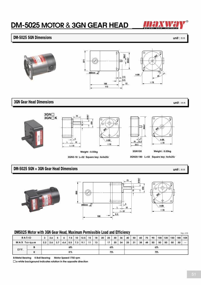
R A T I O
M A X T o r q u e
k g . c m
E F F.B
K
3
2.2
3.6
2.6
5
3.7
6
4.4
7.5
5.5
10
7.3
12.5
9.1
15
11
18
13
20 25
17
30
20
36
24
40
25
50
31
60
38
75
48
90
50
100
50
120
50
150
50
180
50
10X
--
68%
81%
65%
75%
63%
70%
DM5025 Motor with 3GN Gear Head, Maximum Permissible Load and Efficiency
a white background indicates rotation in the opposite direction
3GN Gear Head Dimensions unit : m m
DM-5025 SGN + 3GN Gear Head Dimensions unit : m m
DM-5025 SGN Dimensions unit : m m
B:Metal Bearing K:Ball Bearing Motor Speed:1750 rpm
DM-5025 MOTOR & 3GN GEAR HEAD
3GN3GN K
3GN20-180 L=42 Square key: 4x4x25l
Weight : 0.55kg Weight : 0.55kg3GN10X
70L + 32
4-Ø6
Ø82
Ø30
Ø10h
7
L 32
5
25
15
2
12.54-Ø6
70Ø6
4h7
Ø82
38.5
26
3GN3-18 L=32 Square key: 4x4x20l
Ø71
100113
13
6.52.5
300mm
Ø6h7
Ø64h
7
70
45˚
Ø82
4-Ø6Ø6
9
1006.5
300mm
Ø30
Ø10h
7
L 32
L + 32
5
25
15
4-Ø6
70
Ø82
51
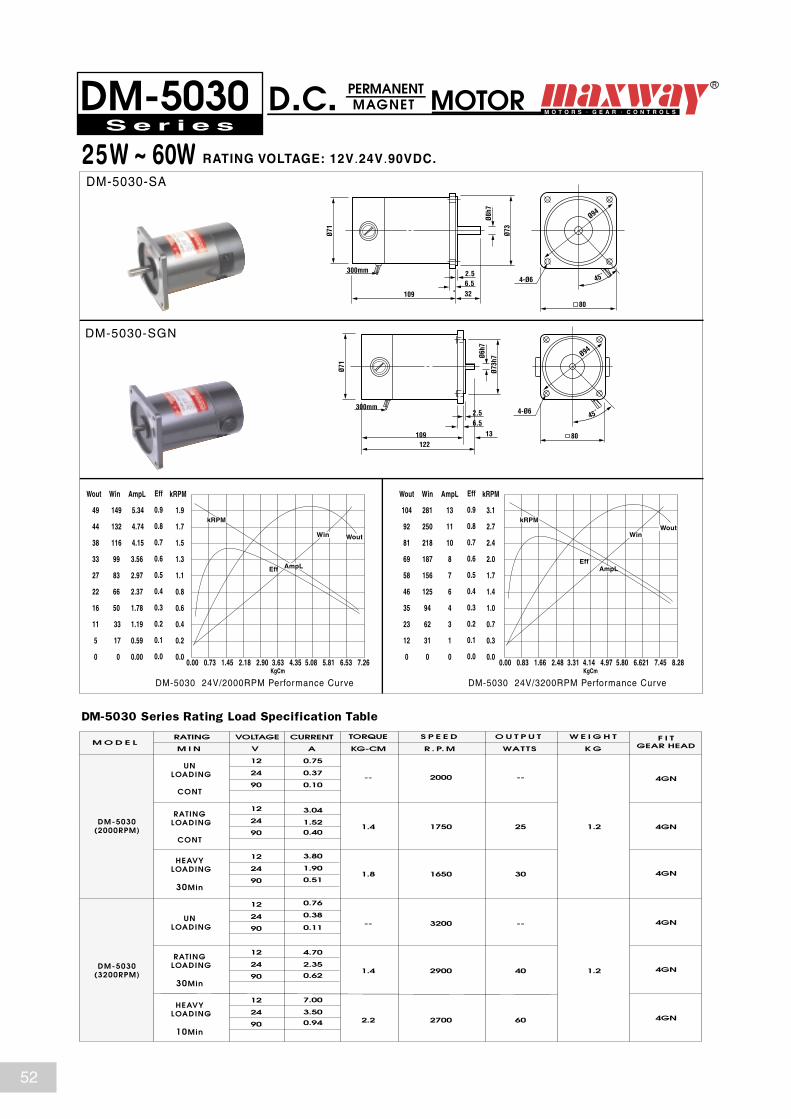
0.00 0.73 1.45 2.18 2.90 3.63 4.35 5.08 5.81 6.53 7.26KgCm
kRPM
AmpLEff
WoutWin
25W ~ 60W RATING VOLTAGE: 12V.24V.90VDC.
PERMANENT MAGNET MOTORDM-5030 D.C.
DM-5030-SA
DM-5030-SGN
DM-5030 24V/2000RPM Performance Curve
S e r i e s
TORQUE S P E E D O U T P U TM O D E L
W E I G H T F I TGEAR HEADKG-CM R . P. M WATTS K G
12 0.75
24 0.37
90
12
24
90
12
24
90
12
24
90
12
24
90
12
24
90
0.10
0.40
0.51
0.11
0.62
0.94
VOLTAGE CURRENT
V A
RATING
M I N
--
UN LOADING
CONT
DM-5030(2000RPM )
DM-5030(3200RPM )
RATING LOADING
CONT
-- 2000
3.04
1.52
0.76
0.38UN LOADING
3.80
1.90HEAVY
LOADING
30Min
RATING LOADING
30Min
4.70
2.35
HEAVY LOADING
10Min
7.00
3.50
25 1.2
4GN
4GN1.4 1750
301.8 1650
--
4GN
4GN-- 3200
401.4 2900 1.2
60
4GN
4GN2.2 2700
DM-5030 Series Rating Load Specification Table
0.00 0.83 1.66 2.48 3.31 4.14 4.97 5.80 6.621 7.45 8.28KgCm
kRPM
AmpLEff
WoutWin
DM-5030 24V/3200RPM Performance Curve
Win
149
132
116
99
83
66
50
33
17
0
AmpL
5.34
4.74
4.15
3.56
2.97
2.37
1.78
1.19
0.59
0.00
Wout
49
44
38
33
27
22
16
11
5
0
Eff
0.9
0.8
0.7
0.6
0.5
0.4
0.3
0.2
0.1
0.0
kRPM
1.9
1.7
1.5
1.3
1.1
0.8
0.6
0.4
0.2
0.0
Win
281
250
218
187
156
125
94
62
31
0
AmpL
13
11
10
8
7
6
4
3
1
0
Wout
104
92
81
69
58
46
35
23
12
0
Eff
0.9
0.8
0.7
0.6
0.5
0.4
0.3
0.2
0.1
0.0
kRPM
3.1
2.7
2.4
2.0
1.7
1.4
1.0
0.7
0.3
0.0
Ø71
109 326.52.5
Ø73
80
Ø94
4-Ø6
Ø71
109122
136.52.5
300mm
300mm
Ø6h7
Ø73h
7Ø8
h7
80
45˚
45˚
Ø94
4-Ø6
52

a white background indicates rotation in the opposite direction
4GN Gear Head Dimensions unit : m m
DM-5030 SGN + 4GN Gear Head Dimensions unit : m m
DM-5030 SGN Dimensions unit : m m
B:Metal Bearing K:Ball Bearing Motor Speed:1750 rpm
DM-5030 MOTOR & 4GN GEAR HEAD
4GN4GN K
Square key : 4x4x25l Square key : 4x4x25l
Weight : 0.65kg Weight : 0.35kg4GN10X
4GN3-18 L=32 4GN20-180 L=45
R A T I O
M A X T o r q u e
k g . c m
E F F.B
K
3
3.4
3.6
4.1
5
5.7
6
6.8
7.5
8.5
10
11.4
12.5
14.2
15
17
18
20
20 25
27
30
32
36
38
40
42
50
53
60
59
75
74
90
80
100
80
120
80
150
80
180
80
10X
--
68%
81%
65%
75%
63%
70%
DM5030 Motor with 4GN Gear Head, Maximum Permissble Load and Efficiency
21
Ø71
109122
6.5
13
2.5300mm
Ø6h7
Ø73h
7
80
45˚
Ø94
4-Ø6
Ø71
122
Ø32
Ø10h
7
L 32L + 32
5
25
15
6.5
26
4-Ø6
80
Ø94
4-Ø6
80
Ø94
Ø32
Ø10h
7
L 32
L + 32
5
25
15
Ø73h
7
213
4-Ø6
80
Ø94
3926
300mm
53

0.0 1.1 2.1 3.2 4.2 5.3 6.4 7.4 8.5 9.5 10.6KgCm
kRPM
AmpL
Wout
Eff
Win
30W ~ 80W RATING VOLTAGE: 12V.24V.90VDC.
PERMANENT MAGNET MOTORDM-5230 D.C.
DM-5230-RA
DM-5230-SGN
DM-5230 24V/2000RPM Performance Curve DM-5230 24V/3200RPM Performance Curve
S e r i e s
TORQUE S P E E D O U T P U TM O D E L
W E I G H T F I TGEAR HEADKG-CM R . P. M WATTS K G
12 0.70
24 0.35
90
12
24
90
12
24
90
12
24
90
12
24
90
12
24
90
0.09
0.46
0.72
0.11
0.85
1.20
VOLTAGE CURRENT
V A
RATING
M I N
--
UN LOADING
CONT
DM-5230(2000RPM )
DM-5230(3200RPM )
RATING LOADING
CONT
-- 2000
3.40
1.70
0.80
0.40UN LOADING
5.40
2.70HEAVY
LOADING
30Min
RATING LOADING
30Min
6.40
3.20
HEAVY LOADING
10Min
9.00
4.50
30 1.7
5GN
5GN1.7 1750
452.7 1600
--
5GN
5GN-- 3200
501.9 2900 1.7
80
5GN
5GN2.9 2700
DM-5230 Series Rating Load Specification Table
0.0 1.3 2.6 3.8 5.1 6.4 7.7 8.9 10.2 11.5 12.8
Wout
125
111
97
83
69
55
42
28
14
0
Win
440
391
342
293
245 196
147
98
49
0
AmpL
18
16
14
12
10
8
6
4
2
0
kRPM
3.1
2.7
2.4
2.0
1.7
1.4
1.0
0.7
0.3
0.0
Eff
0.9
0.8
0.7
0.6
0.5
0.4
0.3
0.2
0.1
0.0
Wout
71
63
55
47
39
32
24
16
8
0
Win
218
194
169
145
121
97
73
48
24
0
AmpL
8.06
7.16
6.27
5.37
4.48
3.58
2.69
1.79
0.90
0.00
kRPM
1.9
1.7
1.5
1.3
1.0
0.8
0.6
0.4
0.2
0.0
Eff
0.9
0.8
0.7
0.6
0.5
0.4
0.3
0.2
0.1
0.0
KgCm
kRPM
Eff
AmpL
Win
Wout
Ø79.
5
120
300mm
157372
Ø10h
7
Ø50h
7
45˚
Ø63
4-M6x1.0P
Ø79.
5
117135
7.518
2.5
3
Ø8.5
Ø83h
7
90
Ø104
4-Ø6.5
54

a white background indicates rotation in the opposite direction
5GN Gear Head Dimensions unit : m m
DM-5230 SGN + 5GN Gear Head Dimensions unit : m m
DM-5230 SGN Dimensions unit : m m
B:Metal Bearing K:Ball Bearing Motor Speed:1750 rmp
DM-5230 MOTOR & 5GN GEAR HEAD
5GN5GN K
Square key : 4x4x25l Square key : 4x4x25l
Weight : 1.5kg Weight : 0.5kg5GN10X
4-Ø7.5
90
Ø104
4-Ø7.5
90
Ø104
Ø36
Ø12h
7
L 32
L + 32
5
25
18
Ø36
Ø12h
7
L 32
L + 32
5
25
18
Ø83h
7
218
4-Ø7.5
90
Ø104
5133
5GN3-18 L=42 5GN20-180 L=60
R A T I O
M A X T o r q u e
k g . c m
E F F.B
K
3
4.2
3.6
5
5
6.9
6
8.3
7.5
11
10
14
12.5
18
15
21
18
25
20 25
32
30
39
36
46
40
51
50
60
60
72
75
90
90
100
100
100
120
100
150
100
180
100
10X
--
68%
81%
65%
75%
63%
70%
DM5230 Motor with 5GN Gear Head, Maximum Permissble Load and Efficiency
Ø79.
5
117
300mm
13518
2.5
Ø8.5
Ø83
90
Ø104
4-Ø6.5Ø7
9.5
117
7.5
55

0.0 2.0 4.1 6.1 8.1 10.1 12.2 14.2 16.2 18.2 20.3KgCm
kRPM
AmpL
Eff
WoutWin
60W ~ 150W RATING VOLTAGE: 12V.24V.90V.180V DC.
PERMANENT MAGNET MOTORDM-5250 D.C.
DM-5250-DA
DM-5250-SGN
DM-5250 24V/2000RPM Performance Curve DM-5250 24V/3200RPM Performance Curve
S e r i e s
TORQUE S P E E D O U T P U TM O D E L
W E I G H T F I TGEAR HEADKG-CM R . P. M WATTS K G
12 0.70
24 0.35
90
180
180
180
180
180
180
12
24
90
12
24
90
12
24
90
12
24
90
12
24
90
0.10
0.05
0.44
0.63
0.11
0.70
1.02
0.88
1.26
0.22
1.4
2.03
VOLTAGE CURRENT
V A
RATING
M I N
--
UN LOADING
CONT
DM-5250(2000RPM )
DM-5250(3200RPM )
RATING LOADING
CONT
-- 2000
6.60
3.30
1.90
0.80UN LOADING
9.40
4.70HEAVY
LOADING
30Min
RATING LOADING
30Min
10.60
5.30
HEAVY LOADING
10Min
15.20
7.60
60 2.14
5GU5GN
5GU5GN
5GU5GN
5GU5GN
5GU5GN
5GU5GN
3.5 1750
855.0 1650
---- 3200
1003.5 2900 2.14
1505.5 2700
DM-5250 Series Rating Load Specification Table
KgCm
-SGU
DM-5250-SGN( )Size of GU Type Shaft
Ø79.
5
137155
7.52.5
(19)18
Ø11.
4
Ø83
90
Ø104
4-Ø6.5
0.0 2.4 4.8 7.2 9.6 12.1 14.5 16.9 19.3 21.7 24.1
kRPM
AmpL
Eff
Wout
Win
Win
413
367
321
275
229
184
138
92
46
0
AmpL
16
15
13
11
9
7
5
4
2
0
Wout
138
123
108
92
77
61
46
31
15
0
Eff
0.9
0.8
0.7
0.6
0.5
0.4
0.3
0.2
0.1
0.0
kRPM
1.9
1.7
1.5
1.3
1.1
0.9
0.6
0.4
0.2
0.0
Win
808
718
628
539
449
359
269
180
90
0
AmpL
32
29
25
22
18
14
11
7
4
0
Wout
302
269
235
201
168
134
101
67
34
0
Eff
0.9
0.8
0.7
0.6
0.5
0.4
0.3
0.2
0.1
0.0
kRPM
3.0
2.7
2.4
2.0
1.7
1.3
1.0
0.7
0.3
0.0
Ø79.
5
140177
2.544.57.5 28.7
300mm
3791
14
115
Ø10
Ø50h
7
49
Ø63
4-M6x1.0P
45˚
56

a white background indicates rotation in the opposite direction
5GN Gear Head Dimensions unit : m m
DM-5250 SGN + 5GN Gear Head Dimensions unit : m m
DM-5250 SGN Dimensions unit : m m
B:Metal Bearing K:Ball Bearing Motor Speed:1750 rpm
DM-5250 MOTOR & GEAR HEAD
Ø79.
5
137
7.5
33
Ø36
Ø12h
7
L 32
L + 32
5
25
18
4-Ø7.5
90
Ø104
4-Ø7.5
90
Ø104
Ø36
Ø12h
7
L 32
L + 32
5
25
18
Ø83h
7
218
4-Ø7.5
90
Ø104
5133
R A T I O
M A X T o r q u e
k g . c m
E F F.B
K
G N
G U
3
8.5
3.6
10.5
5
14
6
17
7.5
22
10
29
12.5
36
15
43
18
51
20 25
66
30
79
36
95
40
105
50
123
60
147
75
150
90
150
100
150
120
150
150
150
180
150
10X
--
68%
81%
65%
75%
63%
70%
8.5 10.5 14 17 22 29 36 40 48 66 79 95 105 123 147 183 200 200 200 200 200 --53
DM5250 Motor with 5GN Gear Head, Maximum Permissible Load and Efficiency
5GN10X
Square key 4 x4 x25l Square key 4 x4 x25l
5GU KB Gear Head Dimensions,Please check next page.
5GN3-18 L=42
Weight:1.5kg Weight:0.5kg
5GN20-180 L=60
5GN5GN K
5GU
5GU5GN
DM-5250-SGN
DM-5250-SGN
( )Size of GU Type Shaft
-SGU
Ø79.
5137
300mm
15518
(19)
2.5
Ø8.5
(Ø11
.4)
Ø83
90
Ø104
4-Ø6.5
300mm
5GU KB5GU K
( Also can connect TYPE )
57
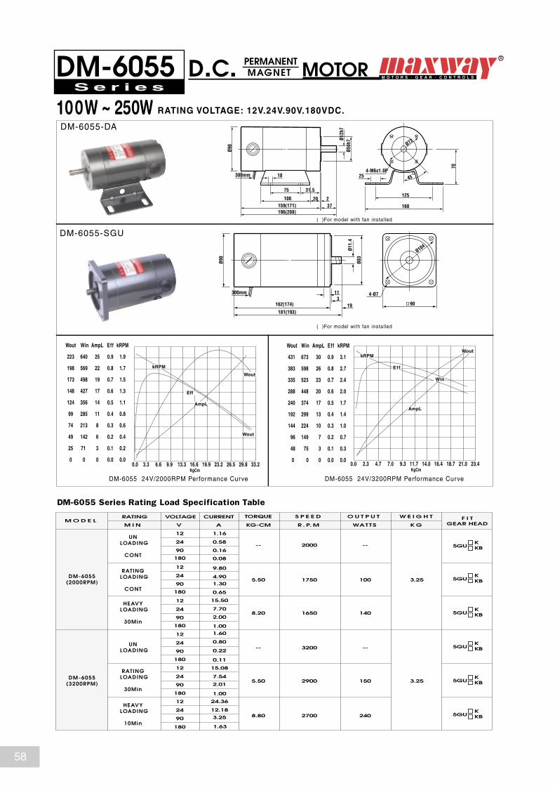
0.0 3.3 6.6 9.9 13.3 16.6 19.9 23.2 26.5 29.8 33.2KgCm
kRPM
AmpL
Wout
Eff
Wout
100W ~ 250W RATING VOLTAGE: 12V.24V.90V.180VDC.
PERMANENT MAGNET MOTORDM-6055 D.C.
DM-6055-DA
DM-6055-SGU
DM-6055 24V/2000RPM Performance Curve DM-6055 24V/3200RPM Performance Curve
S e r i e s
TORQUE S P E E D O U T P U TM O D E L
W E I G H T F I TGEAR HEADKG-CM R . P. M WATTS K G
12 1.16
24 0.58
90
180
180
180
180
180
180
12
24
90
12
24
90
12
24
90
12
24
90
12
24
90
0.16
0.08
0.65
1.00
0.11
1.00
1.63
1.30
2.00
0.22
2.01
3.25
VOLTAGE CURRENT
V A
RATING
M I N
--
UN LOADING
CONT
DM-6055(2000RPM )
DM-6055(3200RPM )
RATING LOADING
CONT
-- 2000
9.80
4.90
1.60
0.80UN LOADING
15.50
7.70HEAVY
LOADING
30Min
RATING LOADING
30Min
15.08
7.54
HEAVY LOADING
10Min
24.36
12.18
100 3.25
5GUKKB
5.50 1750
1408.20 1650
---- 3200
1505.50 2900 3.25
2408.80 2700
DM-6055 Series Rating Load Specification Table
0.0 2.3 4.7 7.0 9.3 11.7 14.0 16.4 18.7 21.0 23.4
Wout
431
383
335
288
240
192
144
96
48
0
Win
673
598
523
448
374 299
224
149
75
0
AmpL
30
26
23
20
17
13
10
7
3
0
kRPM
3.1
2.7
2.4
2.0
1.7
1.4
1.0
0.7
0.3
0.0
Eff
0.9
0.8
0.7
0.6
0.5
0.4
0.3
0.2
0.1
0.0
Wout
223
198
173
148
124
99
74
49
25
0
Win
640
569
498
427
356
285
213
142
71
0
AmpL
25
22
19
17
14
11
8
6
3
0
kRPM
1.9
1.7
1.5
1.3
1.1
0.8
0.6
0.4
0.2
0.0
Eff
0.9
0.8
0.7
0.6
0.5
0.4
0.3
0.2
0.1
0.0
KgCm
kRPM
Eff
AmpL
Win
Wout
5GUKKB
5GUKKB
5GUKKB
5GUKKB
5GUKKB
Ø90
159(171)100
196(208)
125
25
160220
31.575
10
37
Ø12h
7Ø5
0h7
70
Ø72
4-M6x1.0P
Ø90
300mm
181(193)
162(174) 193
300mm 11
Ø11.
4
Ø83
90
Ø104
4-Ø7
45˚
( )For model with fan installed
( )For model with fan installed
58

a white background indicates rotation in the opposite direction
5GU K TYPE Gear Head Dimensions unit : m m
DM-6055 SGU + 5GU KB Gear Head Dimensions unit : m m
KB3-18 L=58 Square key 5x5x25 KB20-18 L=60 Square key 5x5x25
DM-6055 SGU Dimensions unit : m m
B: Metal Bearing K: Ball Bearing Motor speed: 1750 RPM
DM-6055 MOTOR& GEAR HEAD5GU K 5GU KB
Square key 5x5x25
5GU K
5GU KB
R A T I O
M A X T o r q u e
k g . c m
E F F.B
K
3
13
3.6
16
5
22
6
27
7.5
33
10
45
12.5
56
15
62
18
74 83
20 25
103
30
123
36
149
40
165
50
192
60
200
75
200
90
200
100
200
120
200
150
200
180
200
10X
--
68%
81%
65%
75%
63%
70%
DM6055 Motor with Gear Head, Maximum Permissble Load and Efficiency5GU KB5GU K
Ø90
181 (193)
11
4-Ø7.5
90
Ø104
33
Ø36
Ø15h
7
L 32
L + 32
5
25
118
Ø90
162 (174)181 (193)
193
300mm 11
Ø11.
4
Ø83
90
Ø104
4-Ø7
4-Ø7
60
36
4-Ø8.5
Ø104
6090110
130
18
Ø34
Ø15h
7
65102
3710128 45
25
( )For model with fan installed
( )For model with fan installed
59

50W ~ 80W20W ~ 30W
RATING VOLTAGE: 12V.24V.90VDC.
PERMANENT MAGNET MOTORDS-
DS-4530-SGN
DS-5030-SA
DS-4530 90V/2500RPM Performance Curve DS-5030 90V/3600RPM Performance Curve
S e r i e s
TORQUE S P E E D O U T P U TM O D E L
W E I G H T F I TGEAR HEADKG-CM R . P. M WATTS K G
12 0.12
24 0.06
90
12
24
90
12
24
90
12
24
90
12
24
90
12
24
90
0.02
0.34
0.55
0.09
0.74
1.26
VOLTAGE CURRENT
V A
RATING
M I N
--
UN LOADING
CONT
DS-4530(2500RPM )
DS-5030(3600RPM )
RATING LOADING
30Min
-- 2500
2.56
1.28
0.68
0.34UN
LOADING
CONT
4.20
2.10HEAVY
LOADING
10Min
RATING LOADING
20Min
5.55
2.78
HEAVY LOADING
10Min
2.36
4.73
20 0.970.95 2100
301.60 1850
---- 3600
501.52 3200 1.2
802.76 2900
DM- Series Rating Load Specification Table
D.C.50304530
-SGN
45305030
DS-5030-SGN
0.0 1.1 2.3 3.4 4.5 5.7 6.8 8.0 9.1 10.2 11.4
Wout
126
112
98
84
70
56
42
28
14
0
Win
449
399
349
299
249 199
150
100
50
0
AmpL
5.03
4.47
3.91
3.36
2.80
2.24
1.68
1.12
0.56
0.00
kRPM
3.4
3.0
2.6
2.2
1.9
1.5
1.1
0.7
0.4
0.0
Eff
0.9
0.8
0.7
0.6
0.5
0.4
0.3
0.2
0.1
0.0
KgCm
kRPM
Eff
AmpL
Win
Wout
0.0 0.38 0.76 1.14 1.52 1.90 2.28 2.66 3.05 3.43 3.81
Wout
37
33
29
25
21
17
12
8
4
0
Win
97
87
76
65
54 43
32
22
11
0
AmpL
1.09
0.97
0.85
0.73
0.61
0.49
0.36
0.24
0.12
0.00
kRPM
2.3
2.1
1.8
1.6
1.3
1.0
0.8
0.5
0.3
0.0
Eff
0.9
0.8
0.7
0.6
0.5
0.4
0.3
0.2
0.1
0.0
KgCm
kRPM
Eff
AmpL
Win
Wout
Ø63
Ø30
Ø8
99.573.3
14 Ø12x1.2t
Ø70
70
Ø82
4-Ø5.5
Ø71
108 14.5
10
Ø73.
5
8h9
80
Ø94
4-Ø5
unit : m m
60
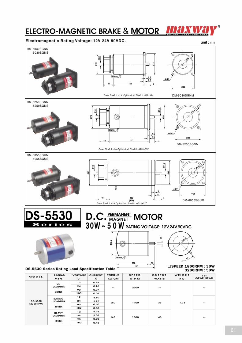
30W ~ 5 0 W RATING VOLTAGE: 12V.24V.90VDC.
DS-5530 D.C. MOTORS e r i e s
TORQUE S P E E D O U T P U TM O D E L
W E I G H T F I TGEAR HEADKG-CM R . P. M WATTS K G
12 0.52
24 0.26
90
180
180
180
12
24
90
12
24
90
0.07
0.04
0.30
0.45
0.60
0.90
VOLTAGE CURRENT
V A
RATING
M I N
--
UN LOADING
CONT
DS-5530(2200RPM )
RATING LOADING
30Min
-- 2200
4.50
2.25
6.75
3.38HEAVY
LOADING
10Min
35 1.73
--
--
--
2.0 1700
453.0 1500
DS-5530 Series Rating Load Specification Table
Electromagnetic Rating Voltage: 12V.24V.90VDC.
DM-5030SGNM -5030SGNS
DM-5250SGNM -5250SGNS
DM-6055SGUM -6055SGUS
ELECTRO-MAGNETIC BRAKE & MOTOR
PERMANENT MAGNET
SPEED 1800RPM : 30W 3200RPM : 50W
DM-5030SGNMGear Shaft:L=13 Cylindrical Shaft:L=Ø8x32l
Gear Shaft:L=18 Cylindrical Shaft:L=Ø10x37l
Gear Shaft:L=19 Cylindrical Shaft:L=Ø12x37l
DM-5250SGNM
DM-6055SGUM
Ø70
122
300mm 2.56.5
300mm
300mm
L40
Ø73
80
Ø94
4-Ø6
Ø10
Ø90
162(174)
4011
L
3
Ø11.
4
Ø83
90
Ø104
4-Ø7
Ø85.
5
112 20132
Ø8
45˚
Ø85.5
Ø79
Ø10
40 1377.5
L
2.5
Ø8.5
Ø83
90
Ø104
4-Ø6.5
Ø8h7
unit : m m
61

Portable Bag Closer Motors
RATING VOLTAGE: 12V.24VDC.110V.115V.220V.230V.240VAC.
SERIES MOTOR SM-73BP
SM-73BP-N
FOR NEW LONG TYPE
FOR FISCHBEIN TYPE
SM-73BP-F
SM-73BP-N(-F)24VDC/10500RPM Performance Curve
Both type of motors are applicable for new long. Fischbein. Siruba. Yao Han. Diamond.
SM-73BP-N(-F)110VAC/10500RPM Performance Curve
S e r i e s
TORQUE S P E E D O U T P U TM O D E L
W E I G H TACCESSORY
KG-CM R . P. M WATTS K G
12 8.60
24 4.30
110
115
220
230
240
12
24
110
115
220
230
240
0.60
0.57
0.27
VOLTAGE CURRENT
V A
RATING
M I N
--
UN LOADING
CONT
SM-73BP(N-TYPE )(F-TYPE )
RATING LOADING
30Min
-- 18000
0.30
0.28
12.84
6.42
1.40
1.34
0.64
0.70
0.67
90
N: 1.62
F: 1.63
0.80 10500
SM-73BP Series Rating load Specifications Table
90W
N-TYPEPULLEY&
BASE
F-TYPEPULLEY&
BASE
0.00 0.42 0.83 1.25 1.66 2.08 2.49 2.91 3.33 3.74 4.16
Wout
230
205
179
154
128
102
77
51
26
0
Win
423
376
329
282
235 188
141
94
47
0
AmpL
18
16
14
12
10
8
6
4
2
0
kRPM
17
15
14
12
10
8
6
4
2
0
Eff
0.9
0.8
0.7
0.6
0.5
0.4
0.3
0.2
0.1
0.0
KgCm
kRPM
Eff
AmpL
Win
Wout
0.00 0.28 0.56 0.83 1.11 1.39 1.67 1.94 2.22 2.50 2.78
Wout
156
139
121
104
87
69
52
35
17
0
Win
257
230
201
172
144 115
86
57
29
0
AmpL
2.78
2.74
2.16
1.85
1.54
1.24
0.93
0.62
0.31
0.00
kRPM
17
15
13
11
9
8
6
4
2
0
Eff
0.9
0.8
0.7
0.6
0.5
0.4
0.3
0.2
0.1
0.0
KgCm
kRPM
Eff
AmpL
Win
Wout
11270 5
5
2-Ø5R56.547 8
Cord (160mm)
24
26
Ø8
96.4
0
Ø75.
8Ø7
5.8
24
26
Ø851
15
7.25
88.9
11241.25 27.75
65.4 15
26
Cord (160mm)
2-Ø5R56.5
62

RATED VOLTAGE: 110V.115V.220V.230VAC.
SERIES MOTORSM-7338OA
SM-7338-OA
SM-7338-OA(M)
SM-7338-OA 115VAC/12000RPM Performance Curve SM-7338-OA 230VAC/12000RPM Performance Curve
S e r i e s
SM-7338 Series Rating Load Specifications Table
100W ~ 1 5 0 WFor Grinder, Centrifuge, Pulverizer ...
0.00 0.31 0.63 0.94 1.25 1.57 1.88 2.19 2.50 2.82 3.13
Wout
182
162
142
121
101
81
61
40
20
0
Win
337
299
262
225
187 150
112
75
37
0
AmpL
3.37
3.00
2.62
2.25
1.87
1.50
1.12
0.75
0.37
0
kRPM
16
14
12
11
9
7
5
4
2
0
Eff
0.9
0.8
0.7
0.6
0.5
0.4
0.3
0.2
0.1
0.0
KgCm
kRPM
Eff
AmpL
Win
Wout
0.00 0.31 0.63 0.94 1.25 1.57 1.88 2.19 2.50 2.82 3.13
Wout
209
186
163
140
116
93
70
47
23
0
Win
362
322
282
241
201 161
121
80
40
0
AmpL
1.78
1.58
1.38
1.19
0.99
0.79
0.59
0.40
0.20
0.00
kRPM
17
15
13
11
9
8
6
4
2
0
Eff
0.9
0.8
0.7
0.6
0.5
0.4
0.3
0.2
0.1
0.0
KgCm
kRPM
Eff
AmpL
Win
Wout
TORQUE S P E E D O U T P U TM O D E L
W E I G H TACCESSORY
KG-CM R . P. M WATTS K G
110 1.00
115 0.90
220
230
110
115
220
230
230
110
115
220
0.50
0.45
0.84
0.80
1.10
1.15
VOLTAGE CURRENT
V A
RATING
M I N
--
UN LOADING
CONT
SM-7338-OARATING
LOADING
30Min
-- 18,000
1.67
1.60
2.30
2.20HEAVY
LOADING
10Min
100 1.43
ADD WithFeedback
orSpeed
Controller0.85 12,000
1501.60 10,000
12784
36
48
48
4-M4x0.7P
38 39 3.550
42
Ø10
62 2424
13784
3638 39 3.55010
42
Ø10
62
Ø7.5
4-M4x0.7P
63

VARIABLE SPEED CONTROLLER D.C. MOTOR & SERIES MOTOR of
M A 90 L S
TYPE: M: D.C.Motor S: Series Motor
INPUT VOLTAGE: A: 100-120VAC B: 200-240VAC
OUTPUT VOLTAGE:90: 90VDC180: 180VDC110: 110VAC220: 220VAC
MAX DUTYPOWER:L : 150W BelowM: 400W BelowH: 750W Below
SHAPE :S : P.C. ModelU: Unit Model
USING FOR 150W BELOW USING FOR 750W BELOW USING FOR 350W BELOWController for D.C. motorunit & P.C. model
Controller for D.C. motorP.C. model
Controller for series motorunit & P.C. model
Model Codes
Specifications of Controller
M-A90L - S-U
M-B180L- S-U
M-A180H-S
S-A110M- S-U
S-B220M- S-U
M-A90H-S
Voltage(V)
110V±10
220V±10
110V±10
220V±10
110V±10
220V±10
Frequency(HZ)
50/60
50/60
50/60
AllowedCurrent
(A)
5
15
5
MAX DutyPower
(W)
150
750
350
SpeedRate
25 : 1
25 : 1
SpeedVariation
5%
5%
5%
ResponseTime
0.5 sec
0.5 sec
0.5 sec
SpeedStability
EXC.
EXC.
EXC.
WorkingTemperature
-10°c ~ +50°c
-10°c ~ +50°c
-10°c ~ +50°c
Type
--
unit : m m
64

VARIABLE SPEED CONTROLLER
DIMENSION FOR P.C. MODEL
P1 P2 AC ACM- M+
STOP
RUN
FU
SE
DC-M
DCMotor
AC AC
FU
SE
M - M+
DC-M
DCMotor
P1 P2
STOP
RUN
AC AC
FU
SE
M- M+
DC-M
SERIESMotor
Fit for D. C. Motor 150 W below unit type dimensional drawing is on page 37
Fit for D. C. Motor 750W below
Fit for series motor 350W below unit type dimensional drawing is on page 37
ELECTROMAGNETIC BRAKE (Negative Actuated Type) Rated Voltage : 12 . 24 . 90 VDC
Terminal Pitch 6.0mm
Terminal Pitch 6.0mm
Terminal Pitch 6.0mm
NSB 0.2
115
3.3 4.93.3
108
41.3
39
120
105
120
74.5
4-Ø3.8
4
4813.5 13
83
unit : m m
D.C. MOTOR & SERIES MOTOR of
74.5
4-Ø3.8
4
4813.5 13
83
Ø69
Ø8 (Ø10
)9
36
4.542
65

SAB TYPE Spring Actuated Fail Safe Brakes
ELECTROMAGNETIC BRAKE ( Negative Actuated Type )
SAB 0.4
SAB 0.8
SAB 1.6
SAB 3.2
SAB 6
SAB 8
SAB 15
SAB 24
A
84
102
127
147
162
188
215
252
B
72
90
112
132
145
170
196
230
C
30
45
56
62
74
84
100
120
DH7
20
30
40
45
55
65
75
90
E
19
24
35
40
48
52
62
72
F
95
110
140
165
185
220
260
300
G
3X4.5
3X5.5
3X6.5
3X6.5
3X9
3X9
6X9
6X11
H
3X4.5
3X5.5
3X6.5
3X6.5
3X9
3X9
6X9
6X11
L
42
48
59
66
76
84
96
108
M
18
20
20
25
30
30
35
40
N
7.8
9.5
12.5
12
14
14
15
17.5
P
17
18
25
31
36
40
33
47
S
6
7
9
9
11
11
11
11
T
3.5
4
4
5
5
6
6
8
V
10°
8°
8°
8°
8°
8°
12°
12°
a
0.2
0.2
0.2
0.3
0.3
0.3
0.4
0.4
ITEMStatic Torque kgf.mVoltage DC-VCapacitor(20 C) wBore dKey Slot bxtWeight kg
SAB 0.40.4
24 96 1902011
4x20.6
SAB 0.80.8
24 96 1902515
5x21.8
SAB 1.61.6
24 96 19030
15 205x2
3
SAB 3.23.2
24 96 19040
20 255x2 7x3
4.8
SAB 66
24 96 19065
25 307x37.3
SAB 88
24 96 19065
25 307x312
SAB 1515
24 96 19085
35 4010x3.5
18
SAB 2424
24 96 190110
40 5010x3.5 12x3.5
27
H7
b
t
Ød H7
ØA
P V
ØD
ØE
(P.C
.D)
B
(P.C
.D)
C
N
H
M
L T
S 400a
G
F
SAB
SIZEITEM
unit:mm
Rated Voltage: 24/96/190 VDC
66

FBD, FBH, FBN TYPE Flange Mounted Brakes
ELECTROMAGNETIC BRAKE
ITEMStatic Torque kgf.mVoltage DC-VCapacitor(20°C) wBore dKey Slot bxtWeight kg
0.60.552411
12 4*1.5 5*2
0.5
1.21.12415
15 205*2 5*2
0.8
2.52.22420
20 255*2 7*3
1.4
54.52425
25 307*3 7*3
2.4
109
2435
30 40
4.8
20172445
40 50
9.5
35352460
50 60
19.5
H7
7*3 10*3.5 12*3.5 15*515
MODEL CODES
FBD
FBD FBH FBNMODEL
2.5
ITEM
. 24
ENERGIZEVOLTAGE
BOREDIAMETER
. 20.
4-K3-H
3-G
400
b
t L2 L3
S
T
2-J
Ød
ØF2
4K
a
N
R
NØ
dØ
E
a
FBD
ØE
ØC
(P.C
.D)
F1
(P.C
.D)
B
T1a
ØA
PR
L1
3-I
3G3-
H
Q
FBH FBN
unit : m m
unit : m m
Rated Voltage:24 VDC
0.6
1.2
2.5
5
10
20
35
A
80
100
125
150
190
230
290
B
72
90
112
137
175
215
270
C
35
42
52
62
80
100
125
E
63
80
100
125
160
200
250
F1
46
60
76
95
120
158
210
F2
26
31
42
50
65
85
105
G
6
8
10
12
14
16
20
H
3.1
4.1
5.1
6.1
8.1
10.2
12.2
I
8
10
12
15
17
19
23
J
M4
M5
M5
M6
M6
M8
M10
K
5
6
7
7
10
10
12
L1
22
24.5
28
31
35
41.5
48
L2
37
44.5
53
61
73
86.5
102
L3
25.5
28.5
33
37
42
50.5
59
N
15
20
25
30
38
45
54
P
2
2.5
3
3.5
4
5
6
Q
3.5
4.3
5
5.5
6
7
8
R
18
20
22
24
26
30
35
T1
2
2
2.5
3
3
4
5
S
25.5
28.5
33
.37
42
50.5
59
a
0.2
0.2
0.2
0.3
0.3
0.4
0.5
T
6
8
10
12
15
18
22
h8 H8SIZE
ITEM
67

UNIVERSAL STANDARD
BAKELITE BRONZE-CARBON BRUSHES SEAT
Material NumberQuality of Material
Insulation ResistanceDielectric StrengthProof. Temp.
: Bakelite T373J ( Grade electric use ): Tubing, Bronze ( CNS 5127 ) Bar, Bronze ( JIS, H3250, C3604 ): 500 VDC / 30 MΩ above: 1500 VAC / MIN: 170 °C
801 802 803 804
805 806 807 808
RL-SERIES
RF-SERIES
601 602 603 604
605 606 607 608
609 610 611 612
614 615 616 617
618 619
TYPE
RL601
RL602
RL603
RL604
RL605
RL606
RL607
RL608
RL609
RL610
RL611
RL612
RL613
RL614
RL615
RL616
RL617
RL618
RL619
A
27.10
27.55
23.15
22.6
21.7
20.2
19
18.5
18.5
16.6
16.6
16.6
15.1
26.1
24
21.9
23.1
17
17
B
25.20
25.75
22
21
19.9
19.25
18
17
17
15.6
15.6
15.6
13.13
-
-
-
21.5
16
16
C
21.15
21.15
18
16
15.2
15.2
13
13
13
12
12
12
9
21.15
19.5
18
18
12
12
M
20
20
18
16
16
13
13
12
13
12
12
12
10
20
18
18
18
12
12
L1
27
26.7
24.7
24.3
24.6
22.9
18
17.75
17.75
21.6
21.6
21.6
12.5
23.5
25.5
22.1
23
22.2
19.2
L2
35
33.5
31
30.65
31.55
30
23.5
22.3
22.3
27
27
27
17.3
31
33
29.1
31
28.1
26.6
D"CUT
24.8
20.9
20.20
18.20
16.17
16.17
14.8
14.8
14.8
A
7
7
6.5
7
6
6
6.5
6.5
5
6.5
6
6
5
7
7
6.5
6.5
5
5
B
17
17
13.5
11
10
10
7.5
7.5
8
7.5
8
6.5
5
17
15
13.5
13.5
8
8
C
10
10
10
8.5
9
9
-
-
6.5
-
6.5
6.5
-
10
10
10
10
6.5
6.5
D
21.15
21.15
18
16
15.2
15.2
13
13
13
12
12
12
9
21.15
19.5
18
18
12
12
L
26
26
25
23
23
23
16.5
16.5
16.5
22
22
22
12
24
26
23
23
19.5
19.5
HxWxL
7x17xL
7x17xL
6.5x13.5xL
7x11xL
6x10xL
6x10xL
6.5x7.5xL
6.5x7.5xL
5x8xL
6.5x7.5xL
6x8xL
6x6.5xL
5x5xL
7x17xL
7x15xL
6.5x13.5xL
6.5x13.5xL
5x8xL
5x8xL
Dimensions of Bakelite Dimensions of Bronze
TYPE
RF801
RF802
RF803
RF804
RF805
RF806
RF807
A
27.15
27.15
20
20
16.5
16.8
19
B
25.3
25.3
17.95
17.95
15.68
16.1
17
C M
20
20
14
14
12
12
13
L1
27
27
23
23
21.8
24
23
L2
35
37
30.5
30.5
27.4
28.1
28.5
D"CUT
19.10
19.10
14.80
14.82
A
8.5
7
7
6
6
5
6
B
16
17
11
10
8
8
9
C
12
12
9.7
8.5
6.5
6.2
6.5
D L
26.85
26.85
24.5
24.5
22
21
21.3
HxWxL
8.5x16xL
7x17xL
7x11xL
6x10xL
6x8xL
5x8xL
6x9xL
Dimensions of Bakelite Dimensions of Bronze
Sizes ofCarbon Brushes
unit : m m
unit : m m
L1
ØC
L2
MØA
ØC
L1
L2
MØB
ØA
B
A -0.09-0.07
+0.0
9+0
.02
3Ø
ØD
L
L1 L1
L2 L2
A AB M
L A
B
ØC
+0.06+0.02
+0.0
8+0
.02
Professional Manufacturer of
According to the specifications
Sizes ofCarbon Brushes
68

Universal Standand of Carbon Brushes
PROFESSIONAL MANUFACTURER OFVARIOUS CARBON BRUSHES
Information above is for reference, only we can help you find out the right brushes to meet your specific require.
Carbon Brushes of Motors
Carbon Brushes of Power Tools
More information is available upon request.
Origin of Raw Material
Category,Material
Specific Gravity
Specific ImpedanceµΩ/cm2
Hardness (Shore) (HS)
Bending Strength kg/cm2
Coefficient of Fr iction
Coefficient of Voltage Drop (V)
Current Density A/cm2
Black Lead of Carbon/Electr ic/Natural/Resin
1.38~1.93
1200~230,000
15°~50°
50~320kg
H 0.25 Above M 0.20~0.25
H 2. 0 Above M 1.0~2.0
Black Lead of Metal
2.30~7.65
5~1000
12°~18°
170~1200
L 0.20 Below
L 1.0 Below
Japan & Germany
6~20A
69

METALLURGY POWDER PARTS
POWDER METALLURGY FEATURES : 1. Fully automatic mass produced, lower cost.
2. Requires no oil-feeding for long operation.
3. Applicable to low and high speed, good quality
in lubrication and low friction.
4. High Precision and fine surface.
5. Smooth running, low noise, and long mechanical
service life.
From Design to Production
Professional Manufacturer of
: Iron system , Copper system , Stainless steel system , Copper & Iron system , B.C.F: Multicolored plating . Zinc plating . Chromium plating . Nickel plating . Copper plating: 6.3 g/cm3 ~ 7.0 g/cm3
: 35°C ~ 38°C ( Copperizing heat Treatment after to 45°(HRC)): Grade 5 ~ 7 class ( Special order is up to Grade 4 ): + 0.01mm~ 0.03 mm
MATERIAL
PLATING DENSITYHARDNESSGRADE FOR GEAR BORE-TOLERANCE
APPLICATIONS : 1. Gearing, motor parts. 2. Automotive parts. 3. Household apparatus 4. Sewing machines 5. Agricultural machinery parts 6. Office equipment parts 7. Toy motor 8. Tools parts 9. Lock parts
Oil Impregnated Bearing Industrial Machinery Parts
After copperizing & heat Treatment, its' Hardness is up to 45° (HRC)
70

UNIVERSAL STANDARD
Professional ProductionFOR MOTOR SHAFT
Common Use Steel Notation
Steel,Category
JIS
SAE
Steel,lowcarbon
S15C
Steel,mediumcarbon
S45C
1045
Steel,chrome-molybdenum
alloy low carbon
SCM 415(SCM 21)
4118
Steel,chrome-molybdenum alloy medium
carbon
SCM-440(SCM 4)
4140
Austenite steel,stainless
SUS 303. 304
Martensite steel,stainless
SUS 410.416
Main of Use
Shaft DiameterHardnessAccuracy of FinishRoundness
: • DC/AC motor shaft • Gear reducer shaft • House-hold electric motor shaft : • Office machine motor shaft • Other fine finish shaft: ø5 ~ ø25 (mm): Heat Treatment 45° HRC (For 1045 & 4140 only): ±0.003 mm: ±0.003 mm
71

DESIGN • MOLD MAKING • DIE CASTING • MACHINING & SURFACE FINISH
MOLD MAKING
Molds for Die Casting & Injection Molding
Die Casting Factory
Aluminum Alloy Parts
72

No.1,Lane 61,Mingyuan St., Sanchong City,Taipei, TaiwanTel:+886 2 2989 0399 Fax:+886 2 2989 2358 , +886 2 2971 6618http://www.motor-net.come-mail:[email protected]
MAXWAY Electric Industrial Co., Ltd.
Maxway 2000 T-1
馬 速 威 企 業 有 限 公 司