for ASSEM8L Y OPERATION WARRANTY...
30
I ! - ,--'- .. Y:~'~2:00 INSTRUCTION MANUAL for ASSEM8L Y 0 F OPERATION COMMERCIAL MAINTENANCE YAZOO RIDING TRACTORS WARRANTY . , PARTS . YR-36 .- YR-42 YR-48 .. YR-60 YR-76 VAlaa TRAILER " YT -10 HD - !!~QR. W P.O. BOX 4449 /3607 LIVINGSTON ROAD 'PHONE: 366.6421 j JACKSON, MISSISSIPPI 39216 EFFECTIVE SEPTEMBER 1, 1979 " r
Transcript of for ASSEM8L Y OPERATION WARRANTY...

I! - ,--'- ..
Y:~'~2:00INSTRUCTION MANUAL
for
ASSEM8L Y
0 F OPERATION
COMMERCIAL MAINTENANCE
YAZOO RIDING TRACTORS WARRANTY
. , PARTS
. YR-36
.- YR-42YR-48
.. YR-60YR-76VAlaa TRAILER "
YT -10 HD-
!!~QR. WP.O. BOX 4449 /3607 LIVINGSTON ROAD'PHONE: 366.6421 j JACKSON, MISSISSIPPI 39216 EFFECTIVE SEPTEMBER 1, 1979
"
r

i
.,
: 1. PREPARATION OF MACHINES 3. OPERATION:
.1 FOR OPERATION: (a) Service engine and transmission before1 .i () Rf . If .. . starting.1 a e er to engine manua or servIcing engine. b I h. hi., (b) Remove transmission inspection cover and () Se ect Ig or ow range. Do not shiftI fill with 3Y2 quarts (clutch run Y2 way in unless clutch lever is in neutral position.
oil.) of SAE #30 weight motor oil. (below (c) ~ith clutch lever i~ neutral and blades: freezing use SAE 20) dlsengage.d: s.tart, engine. .
~; (c) Service battery with electrolyte for dry For famillarizatl~n, .run engine at sl.ow c"1 charged batteries. spe~d and machl~e In low ~~r. Cutting ,';
section should be In down position, EASE c
2. CONTROLS the clutch lever forward or back (which-
i (a) Your Yazoo Rider is equipped with two ever is desired);l' forward gears. The gear selection is ob- WARNING: If the clutch lever is jerked
tained by moving the gear shift to the left into reverse the rear end of the machinefor low and to the right for high. Use a will have a tendency to raise off thequick motion when shifting from high to ground.low (or low to high). Do not stop between (d) When cutting section is not in use it maygears. Shifting should only be done when be raised by pulling the cutting section '7;,~i,':~1clutch is not engaged. There is no netural control lever back into the lock bracket ~position for this shift. located on the lower right side of the ~,:. (b) The Rider is put in motion by moving the frame. '.,
clutch lever forward for forward and to the (e) To cut, push the blade engagement lever ~rear for reverse. forward to the lock position. In high grass ~~
(c) The throttle control is on the left side of the guards may be raised to allow a rapid ;';)'f?:the engine on the YR-60 and on the right discharge of grass.side on the YR-76. The throttle control on WARNING: This Jnower, as with anythe Yr-42 and YR-48 is a remote control heavy machinery, SHOULD NOT BE OP- ;:secured to the left side of the upper steer- ERATED ON INCLINES IN EXCESS OF ~.ing bracket. The YR-36 throttle control is 15°. On slight inclines, additional traction ~.
also remote control and is attached to the may be obtained by pulling back slightly ;tubing frame on the left side. on the cutting section lift lever. ;
(d) Blades are engaged when the blade engage- WARNING: The foot-operated transmiss- .';1 ment lever is in the forward position. ion brake is extremely sensitive and should'z (e) The cutting se~tion co.ntr~llever raises and be actuated with light, even pressure on
'1 low~rs the ~~ttlng section In and out of the the brake pedal, "."""';;"'-:~ cutting position. -,~ (f) The brake is to the right of the steeringj post and is operated with the right foot.
cY.",..
, .;,{,::fi
,!
1
I' 1l/2"CLIT 2" CUT 2~IICUT I
~:
1"
...]1 3# Cu T 3'/:J." CUT 4. ~CUT
".~,.;
,c,
...~
~: . :'":1:'.
- ~

4. MACHINE ADJUSTMENT:(a) The cutting height may be adjusted by changing belts on the YR-36, YR-42, YR-48, YR-60
the position of the cutting section carriage and YR-76 only are super HC 3V belts. Thewheels - See Fig. 1. To adjust the front and tension of these belts should be checked asrear wheels on the YR-42, YR-48, YR-60 and follows:YR-76 models, remove the entire spindle as- 1. Measure the span length.sembly and place the spacers either above or 2, At the center of the span, apply a forcebelow the mounting sleeve, whichever is desired, with a spring scale (at right angles to theTo adjust the rear wheels on the YR-36 model, span as shown in Fig. 3) large enoughremove the bolts that hold the whee! brackets to deflect the belt 1 /64 inch per inch ofto the frame. Position the bracket as desired, span.then replace and secure bolts. Front wheel 3, The force should be within the range given . .adjustment on the YR-36 is with spacers, as the below for a properly tensioned drive.other models. The adjustments maybe graduated 0,0, of small sheave Tension in Ibs.in increments of half inches or inches as shown 2V2 inch to 4V2 ,.,.3 to 4V2 Ibs, .-in Fig. 1, 43/4 inch to 6 4 to 6 Ibs.
UPPER IDLER.
SET SCRE~§ ENGINE PULLEY--=-=---~-- ---
LOWE~ IDLE
SSION Pu LLEY
FIGURE 2
III (b) The propelling drive belt may be adjusted by (d) The secondary wing blade drive belts are ad-
first removing the belt guard, Then loosen the justed by first removing the hood. Loosen theset screws that hold the upper idler arm in bolts that secure the idlers and reposition theposition. Adjustment is made by sliding the arm idlers for desired belt tension. See Fig. 3., B h .dl II ' Retighten bolts.In or ou~. e sur,e tel er pu eys, are In (e) ADDITIONAL WARNING: Adjustments should~orrect allignment with the ~elt befor~ retl~hten- never be attempted with the engine runningIng only enough to propel the machIne without other than adjustments to the engine itself whichslippage. The bottom idler should be lined up are required to be made with the engine running.with the engine pulley and transmission pulley 5, MAINTENANCE TIPS:and not used as a belt adjustment - $ee Fig. 2. (a) Blades
(c) The primary blade drive belts are adjusted by (1) Be sure. the blad~s are out of gear and s~arklengthening or shorterling the cutting section plug wires are disconnected before removing.
t ' S F' 3 Th '. h " d (2) The blades are fastened to the hub shaft withconnec Ing arms - ee Ig. . IS IS ac leveI ft h d t d I k h" e an nu s an oc was ers.
by removing the 5/8 Inch bolt that holds the (3) Blades must be installed to rotate in a counterconnecting arm end to the frame and screwing clockwise direction.the rod end in or out. The blade engagement (4) Do not sharpen the end of the blades. Sharpen-lever must be in the engaged position when ing the tips will result in excess end gap caus-checking belt tension, The primary blade drive ing uneven mowing.

Shi fter Sleeve
iForward Clutch
R Forward Gear,I
j c ..;"C'"i£~; .
~'\
~'"l'"j
Screw Driver #1..jI, 5. Roll machine slightly until edge
6. Pry the lock spring up unti lit of forward drive cup is clear of theclears the notches on the adjusting end 0 f the lock sp ring
FIGURE 4 B
If the clutch lever has an excessive amount of (i) To loosen the clutch, move the adjustingtravel, one or both of the clutches need adjust- collar away from the end of the lock spring.ing. When the lever has approximately 6 inches CAUTI ON: Improper #adjustments in the ad-of travel and will not lock in gear, the adjust- justmentable parts of the mower may result inment is too tight. When properly adjusted, the adnor~al wear~ malfunction, and hazardous
.' operation. It IS suggested that those wholev~r will have a very notlceabl~ o~er-center maintain the equipment are thoroughlyaction when the clutches are locking In forward trained in the proper adjustment techniques
and reverse, and that the mowers are inspected frequentlyClutch Adjustment to insure proper adjustment.
. I . d. d (j) Replace inspection plate and belt guard.(a) Be sure the transaxle drive be t IS a juste
properly. Sealing the Transaxle1 (b) Remove the inspection plate. A gasket and a gasket-forming sealant, # 1-C
(c) I f the reverse clutch is to be adjusted, remove Permatex is used to seal the transaxle housingthe transaxle belt drive guard. flanges. The wheel hubs are also sealed in
(d) Make sure the clutch lever is in neutral. this manner. These surfaces should be tho-(e) Rotate the input shaft until the square end of ~oughly degreased before the sealant is appli-
the adjustment lock spring is visable through ed. A generous amount of permatex should bethe inspection hole. See Fig. 4-B. applied to both sides of the hub washer and
',; (f) Roll the m~chine sl~ghtly until the edge of .the .'xle threads. The axle nut should be tightened~\: forward drive cup IS clear of ~e lock spring. '~l/lrh 100 foot pounds of torque.:';:, (g) Place the end of on~ scre~ driver u~der the 7. PARTS AND WARRANTY
edge of the lock spring. Using the shlfter sle-eve as a heel, pry the lock spring up until it Use only genuine Yazoo parts.cI~ars the notches on. the adjusting c,:>llar. Se.e For efficient, satisfactory service on all ourFI,g. 4-B. °.0 not tWiSt the screw dr~ver as It equipment, factory recommended parts arewill catch In the notches of the adjustment most essential. Much care is taken to assurecolla~.. better and longer trouble-free service. Only-
(h) To tighten the cI.utc~, skiP. one n,:>tch from the finest materials and expert workmanshipthe end of the adjustIng spring placing the se- are used in the manufacture of all replace-cond screw driver in the second notch of ~he ment parts for your Rider by Yazoo Manu-adjustment collar. This will keep the adjusting facturing Company. Equal consideration iscollar from moving more than one notch at a given to component parts secured fromtime. Move the adjusting collar towards the venders.lock spring until the spring end will fall in the .first notch. Always make adjustment in one When ordering replacement parts:notch increments as one notch may be all 1 - Give correct part number.
that is needed.
---

,~
.Y'Io" GUARD/BELT CLEARANCE
,)
.
BLADE SECTION ARM f\)\...\... PRIMARY BLADE DRIVE 8ELTS
-- .1. .-,
E ' FIGURE 3I
. weeks of operation. When the transaxle will not(b) Belt Guards - See Fig. 3, .. ...pull or lock in gear, It IS an Indication that.
(1) The wrap-around guards on the engine and adjustment is needed. When properly adjusted,primary blade hub (cent hub) should have a the transaxle will lock in gear with the clutchminimum of 1/16" clearance between- the lever moving the distances indicated in Fig. 4-A.guard and belt. This. is very important at theends of the guard. The belts should be in theengaged position when measurement is made. A ~I
(2) The guide fingers on the primary blade drive ";;~~~-=-_l___~-. ;'C1'belt idler should be installed with one finger \\ \ e I I'vertical and the other horizontal. R , H, ,c~ iF.
. ,~ ,.!I (I:
(c) Tire Pressure \ ~ ff /;1/T. b .. d . . \'\ ~\\ l~ ","Ire pressure should e malntalne at a minimum \~ ~ ~ tof 8 Ibs. and a maximum of 12 Ibs. PSI. ~\X\ If/,;1
\~\ 1//(d) Service 81 Lubrication - See Fig. 5. \~\ It! FIGURE 4 A
~ 1/(e) Blade drive belt idler bracket.
The blade drive belt idler bracket should haveth I I k d . t th fo d Clutch Lever Movement Distancese ower arm oc e snug agalns e rwarpart of the frame when the blades are in the A - 11 " Reverse Lock to Forward Lock
engaged position. .B 6" free travel In neutral
6. TRANSAXlE ADJUSTMENT C 2Y2" locking forward
"the transaxle employs a twin~ multi-disc Rock- D - 2Y2" locking reverseford Clutch. The outside clutch (next to the F Forwardwheel) is the forward clutch and the inside, the N
N I'. eutra, reverse. Due to the discs wearing and seating
in, adjustment will be required a~ter about three R Reverse
""," ~:~~~1(~::~..", -

2 - Give desired quantity. This warranty does not apply to damage in transit3 - Give description of part(s). or damage caused by mis-use, negligence oraccident,
to alterations or repc:irs done outside the factoryYazoo Manufacturing Company produces only the and I or authorized service stations, nor does itrr 'er itself and not the engine. For service or obligate us to assume any labor charges in connec-rb,..Jlr on the engine, contact the engine manu- tion with the replacement of parts claimed to befacturer's nearest service agent or dealer. defective.
j
Yazoo Master Mower Warranty (Limited) All parts claimed defective must be returned to the! This is a limited warranty as defined by Federal factory for inspection, repair or replacement, with
I j Statues. Each new product is warranted against transportation charges paid.
manufacturing defects in workmanship and/or This warranty specificall.y excludes engines which arematerials under normal use and service. Our warranted separately by their respective manufac-. obligation under this warranty, shari be limited turers. All claims for defective engines or engine
to the replacement to the original retail pur- parts must be made in accord with the engine man-. chaser of any part or parts which, within a ufacturer's warranty.
period of ninety (90) days under normal use We reserve the right to make changes in design
from day of purchase by the purchaser shall be and changes or improvements upon our product
shown to our satisfaction upon examination, to without imposing any obligation upon ourselves tohave become defective due to faulty workman- install the same on a product or products heretoforeship or materials at the factory. manufactured.
Spindle. .
,. , Cutting SectionCarr...e Wheels
EVEI:V 8 HOURSALL PURPOSE GREASE
E..lne 011 Sump& Air Cleaner
SEE ENGINE TransaxleOPERATII/G MAI/UAL MAI.VTAIN OIL LEVEL ""ITH In NT
MOTOR OI!. SO CLUTCH RU.VS I.VAPPROXIMATE!.Y I .! INCH OF OI!.
Clutch II Generator / St :-erSEE EVGlVE .AVL"AL
EVERY 8 HOURSJO II'T OlL Post & Chain
. . Blade Engaging!
EVERY 8 HOURSJO liT OIL
BatteryADD DISTILLED WA TER AS NEEDc'D Rear Wheel 8ear1.gs(TRICK!.c' CHARGE) MIN OF 15 MINUn'S CLEAN AI/D R£PACK III TH ALL PL"RPOSE
St_rl8g Pivot GREASE EI.ERl " .O'TH'
EVERY" HOURSALL PURPOSE GREASE
'-
SERYICE & LUBRICATION .
FIGURE 5

" "'~
YR-36 Parts List - ChassisNo. Part No. Descri tion No. Part No. Descri tion
1 103-034 Axle, Rear Wheel 60 1201-014 Lever, Cutt Sect Lift YR-362 203-003 Battery 61 1201-017 Lever, Clutch, YR-363 204-019 Bearing, Ball 62 1201-034 Lever, Hi/Low Shift YR-364 204-020 Bearing, Ball 63 1204-001 Link, Master #41 Chain5 205-066 Belt, Transmission Drive 64 1205-011 Linkage, Clutch (Short-Rear)6 208-002 Bolt, 3/16-24 x 3/4 RH 65 1205-012 Linkage, Clutch (Long Front)7 208-028 Bolt, 1/4-20 x 1 3/4 RH 66 1401-001 Nut, 3/16-248 208-029 Bolt, 1/4 x 3 1/2 RH 67 1401-010 Nut, 1/4-209 209-026 Bolt, 1/4-20 x 1 HH 68 140'1-020 Nut, 5/16-18
10 209-050 Bolt, 1/4-20 x 2 HH Plated Cap 69 1401-030 Nut, 3/8" USS11 209-108 Bolt, 5/16-18 x 3/4 HH 70 1401-032 Nut, 3/8-2412 209-109 Bolt, 5/16-18 x 3/4 HH Ht. 71 1401-051 Nut, 1/2-2013 209-114 Bolt, 5/16 x 1 Cap Plated 72 1401-056 Nut, 1/2.13 "-
14 209-120 Bolt, 5/16-18 x 1 1/4 HH 73 1401-070 Nut, 5/8-18 Jam15 209-138 Bolt, 5/16-18 x 2 HH (Specify Full Thread) 74 1401-081 Nut, 3/4-16 Lock16 209-150 Bolt, 5/16-18 x 2 1/2 HH 75 1601-001 Pad, Pedal .. .
17 209-350 Bolt, 3/8-16 x 2 1/2 HH 76 1601-003 Pad, Rubber Battery18 209-617 Bolt, 5/8-18 x 1 1/2 77 1601-005 Pad, Foot ;,19 209-494 Bolt, 1/2-13 x 3/4 78 1604-002 Pin, 3/32 x 1 Cotter '"20 214-101 Bracket, Cut Sect. Lift YR-60 79 1608-112 Pulley, 9" Transmission ::
21 214.121 Bracket, Cutting Sect. Lift 80 1608-131 Pulley, Transmission Drive22 214-144 8racket, (Adj.) Lower Steering 81 1608-134 Pulley, glade Drive23 214-148 Bracket, Hi-Lo Lever Mtng. 82 1608-205 Pulley, 3" D~D.S.G. Idler24 214-149 Bracket, Mtgn. Plate 83 1608-206 Pulley, 3 1/2" D.D. D.G. Idler25 214-150 Bracket, Upper Steering 84 1808-019 Rod, Brake26 214-151 Bracket, 'dler Mounting 85 1808-131 Rod, Blade Idler ,27 214-152 Brack~t, Srake Actuating 86 1809-001 Roller, Cable ~ ;~
28 214-206 Bracket, Ass'y Battery 87 1901-003 Screw, #14 x 3/4 Pan Hd. Type A c'1,II.. 4
29 215-022 Bushing, 5/8 I.D. x 13/160.0. Cable Roller 88 1901-005 Screw, 1/4-20 x 1/4 A. Hd. Set30 215-101 Bushing, Upper R. Wheel Yoke 89 1901-006 Screw, 5/16-18 x 1/4 A. Hd. Set31 215-102 Bushing, Lower R. Wheel Yoke 90 1901-009 Screw, 5/16-18 x 5/16 A. Hd, Set32 215-103 Bushing, Steering Bracket 91 1901-033 Screw, 5/16-18 x 3/4 Sq. Hd. Set33 301-019 Cable, Throttle Control 92 1901-034 Screw, 3/8-16 x 3/4 Sq. Hd. Set ~
34 301-030 Cable, Cutting Sect. Lift 93 1903-012 Seat35 301-057 Cable, Ass'y. Neg 94 1904-115 Shaft, Intermediate Steering36 301-058 Cable, Ass'Y'. Pos 95 1904-117 Shaft, Ass'y. Steering37 303-015 Cap, Steering Wheel 96 1904-151 Shaft, Cable Roller38 303-016 Cap, Battery Red 97 1904-152 Shaft, Idler Arm39 303-017 Cap, Battery Black 98 1913-057 Spacer, Axfe, Rear Wheel40 305-046 Chain, #41 Steering 99 1913-029 Spacer, Pipe, 1/4 x 1 7/8 Long41 307-002 Clamp, Cutting Sect. Lift Cable 100 1913-040 Spacer Washer, 5/8 I.D. x 7/8 D.D.42 311-002 Collar, 5/8 Set 101 1916-012 SpriJlg, Cutting Section Lever43 311-003 Collar, 3/4 Set 102 1916-020 Spring, Clutch Lever44 314-049 Cover, Right Hand Battery 103 1916-063 Spring, Cutting Section Lift45 314-050 Cover, Left Hand Battery 104 1916-080 Spring, Seat YR-36/42/48/60/7646 401-002 Decal, Hood 105 1917-044 Sprocket, 36 T. Rear Steering47 501-001 Elbow, Clutch 106 19't7-045 Sprocket, 12 T. Front Steering48 502-011 End, Hi-Lo Selector Rod 107 2301-001 Washer, 3/16 Lock .
49 502-012 End, Clutch Rod 108 2301-003 Washer, 1/4 Lock50 603-004 Fitting, 1/4-28 Self-Tap Zerk 109 2301-004 Washer, 5/16 Lock51 703-003 Grip, 1/2" handle 110 2301-006 Washer, 3/8 Lock . ..52 703-004 Grip,3/4"handle 111 2301-008 Washer,1/2Lock53 704-084 Guard, Steering Gear 112 2301-011 Washer, 5/8 Ext. Star Lock54 704-218 Guard, Belt 113 2301-021 Wa$her, 5/16 Flat55 704-247 Guard, Trans Dr. Belt 114 2301-024 Washer, 1/2 Flat56 705-006 Guide, Belt 115 2301-045 Washer, 5/16 x 1 3/4 Fibre57 1102-012 Key, 1/4 x 1/4 x 3 116 2303-008 Wheel, Steering58 1102-013 Key, 3/16 x 3/4 Woodruff 117 2501 -022 Yoke, R. Whee. Steering59 1201-006 Lever, Blade Engaging 118 2601-027 Yoke 5/16-18. '
y~ZOOU A .n'
FA.CTURI~ G COMpA NY INC P. o. BOX 44.i /3607 LIVINGSTON ROAD-~U A A. . PHONE: (601) 366-6.21 / JACKSON, MISSISSIPPI ~21.
-- - ;:ii;;;c~,Ti'-
. II :'
~i -'-i
. .
~ § E~.::. . ~'" - - - . .', !!!
i :~. ~: = '.; "
~ ""'; ;
~:~""~' :,
,,"
I'1' I.! "
~:1,1f":.-
1
!:
i.
,.
@ ~~~
@@'"' i J g:

~~ ~"'.",.,.- "'I
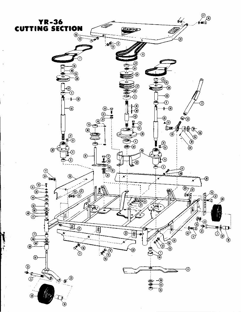
YR-36 Cutting Section Parts List .I
No. Part No. Descri tion No. Part No. Descri tion
1 101-003 Adapter, Left Hand Blade 31 1401-020 Nut, 5/16-182 102-048 Arm, Cutt. Sect. Lift 32 1401-030 Nut, 3/8-16
13 103-045 Axle, Cutting Section 33 1401-070 5/8-18 JamI
4 204-019 Bearing, Ball 34 1401-071 5/8-18 Full i5 204-060 Bearing, Ball 35 1401-073 5/8-18 Left Hand6 205-024 Belt, Left Wing 36 1608-061 Pulley, 3 1/2 x 5/8 D.G. W/K'way7 205-034 Belt, Right Wing 37 1608-062 Pulley, 37/8 x 5/8 D. G. W/K'way8 205-375 Belt, Blade Drive 38 1608-094 Pulley, 3 11/32 x 3/4 S. G. W/K'way .
r9 206-736 Blade, Offset 39 1608-202 Pulley, Wing Idler S. G.10 209-108 Bolt, 5/16-18 x 3/4 HH 40 1806-001 Ring, "0"11 209-114 Bolt, 5/16-18 x 1 HH 41 1901-006 Screw, 5/16-18 x 1/4 A. Hd. .
12 209-327 Bolt, 3/8-16 x 1 1/2 HH 42 1904-022 Shaft, Hub, Intermediate13 A 209-634 Bolt, 5/8-18 x 2 1/4 HH 43 1904-040 Shaft, Hub
Left (Front) Arm Only 44 1906-006 Shield, Dust14 212-005 Bolt, 3/8 x 3/8 Stripper 45 1913-040 Spacer Washer, 5/8 1.0. x 7/80.0.15 214-115 Bracket, Tension, Long 46 1913..046 Spacer, Bottom Left Wing16 214-147 Bracket, Tension, Long 47 1913-047 Spacer, Bottom Right Wing17 215-009 Bushing, Cutt. Sect. Whl. Yoke 48 1913-048 Spacer, Top Right Wing18 215-025 Bushing, Steel Wheel 49 1913-055 Spacer, 3/4 1.0. x 1" Long19 311-002 Collar, 5/8 Set 50 1913-057 Spacer, 3/4 1.0. x 1" Long
Front, Left Side Only 51 2301-004 Washer, 5/16 Lock20 502-004 End, Cutt. Sect. Arm 52 2301-006 Washer, 3/8 Lock21 603-004 Fitting Grease Zerk 53 2301-010 Washer, 5/8 Lock22 704-258 Guard, Belt 54 2301-011 Washer, 5/8 Ext. Star Lock23 704-291 Guard, Front 55 2301-012 Washer, 5/8 Left Hand Lock24 704-292 Guard, Rear 56 2301-021 Washer, 5/16 Flat25 704-293 Guard, L. Side 57 2301-022 Washer, 3/8 Flat26 704-294 Guard, R. Side 58 2301-028 Washer, Flat 3/4 x 1 3/8 0.0. x 13 Ga.27 804-060 Hood . 59 2301-096 Washer, 5/8 Spring Cupped Lock
28 806-019 Housing, Steel Hub 60 2302-004 Wheel 5 x 1.7529 807.033 Hub, Intermediate 61 2501.028 Yoke, Wheel30 1102-001 Key, 3/16 x 3/16 x 1
316-037 Cutting Section Complete
t
WARNING
DO NOT OPERATE ANY YAZOO PIECE OF EQUIPMENTWITHOUT FIRST READING AND UNDERSTANDING THIS MANUAL.
~r". ~
;3 y~ZOOf,'. 0: P. O. BOX 4449/ 3607 LIVINGSTON ROAD
. MANUFACTURING COMPANY. INC. PHONE: (601) 366-6421/JACKSON. MISSISSIPPI 39216
t".: ~- -'
?Y R - 36 '11:, ,~,.~~ ~- /C UT TIN G 5 E C' I~~ ~==--=-;; 1~~:~ ~ - -_/
~~o- : --- Q~~;-@
C:~~~~ ~ oli))~ ~
1
~-@ ~ G@ --~~ ~-@ ,
~~~5--@ ~ tBJ-@ ~ ~ ~ 4531 ~ 8
-@30
5
<!V--V 30
~-@@~ ~~19 --~
\ 1 (~~~~=~~;~~5~1 -t~ ~~: - 29 ~: /""~~I , 54
~ : ~-<D :. 19
5 .~ 56 : @t, ~~ , ' 22 'L- -- -- --- I . I
er@ , : ~: fij\11 ' -51' I ,~
,,
II
@ --~,
,,,,
... '8'",.0, 501:
:J~ ""@' :r ~-.,! ;:.~ -I!{(@.".. - - ., 55@~-- ~ ~-@
@--- ~

""~
YR-42 & YR-48 Parts List - Cutting Section .,
c ,No. Part No. Descri tion No. Part No. Descri tion '1' - - -;i
1 101-003 Adaptor 32 . 704-318 Guard, Rear YR-48 ;2 . 102-039 Arm, Cutting Section (YR-48) 33 804-057 Hood, (YR-42 & YR-48)3 103-095 Axle, Cutter Section 34 806-017 Housing, Hub 6-Hole Ductile Iron t4 204-020 Bear~ng, Idler 35 1102-001 Key, 3/16 x 3/16 x 1 I
5 204-060 Bearing, Hub 36 1401-013 Nut, 1/4 LOCkl'
6 204-076 Bearing: Cutting Section Wheel 37 1401-020 Nut, 5/16-1,137 .. 205-041 Belt, Wing (YR-42) 38 1401-070 Nut, 5/8-18 Jam7 ... 205-144 Belt, Wing (YR-48) 39 1401-072 Nut, 5/18-18 Lock l8 205-380 Belt, Blade Dr. (YR-42 & YR-48) 40 1401-073 Nut, 5/8-18 Left Hand Full .-g ... 206-742 Blade, Offset (YR-42) 41 1608-067 Pulley, Wing Dr..3 1/20.0. x 3/4 Bore9 ... 206-748 Blade, Offset (YR-48) D. G. with 3/16 K'way
10 208-021 Bolt, 1/4 x 3/4 RH 42 1608-068 Pulley, Main Dr. 37/80.0. x 3/4 Bore11 209-051 Bolt, 1/4-20 x 2 D.G. with 3/16 K'way12 209-108 Bolt, 5/16-18 x 3/4 HH 43 1608-094 Pulley, Wing 3 11/32 0.0. x 3/4 Bore13 209-114 Bolt, 5/16-18 x 1 HH S.G. with 3/16 K'way14 209-120 Bolt, Hub, 5/16-18 x 1 1/4 HH 44 1608-202 Pulley, Wing Idler S. G. ('tR-42, 48)15 209-126 Bolt, Hub Guide 5/16-18 x 1 1/2 HH 45 1608-204 Pulley, Center Idler D. G. 2 3/.4 0.0.16 209-314 Bolt, 3/.8-16 x 1 HH (YR-42,48) ,
17 209-617 Bolt, 5/8-18 x 1 1/2 HH 46 1806-001 Ring, "0" J18 209-666 Bolt, 5/8-18 x 53/8 Axle 47 1901-006 ,Screw,Set 5/16 Allen Head 119 212-005 Bolt "1/8x 3/8 Stripper 48 1904-040 Shaft, Hub 3/4" "20 214-102 Bracket, Tension 49 1906-006 Shield, Dust
i
21 214-211 Bracket, Cutting Section Lift 50 1906-012 Shield, Cutting Section Wheel I
22 214-213 Bracket, Chute 51 1913-055 Spacer, 3/4 x 1/2 i
23 215-009 Bushing, Cutting Sect. Wheel Yoke 52 1913-057 Spacer, 3/4 x 124 215-025 Bushing, Spanner 53 2301-004 Washer, 5/16 Lock i25 306-010 Chute, Disc Yr 42 & 48 54 2301 -006 Washer, 3/8 Lock '
26 309-030 Clip, Hairpin (YR-42 Only) 55 2301-010 Washer, 5/8 Lock27 311-002 Collar, 5/8 Set 56 2301-011 Washer, 5/8 Star Lock28 502-004 End, Cuttif'g Section Arm 57 2301 -012 Washer, 5/8 Left Hand Lock29 603-004 Fitting, Zerk Grease 58 2301 -021 Washer, 5/16 Flat30 . 704-086 Guard Left Front (YR-48) 59 2301-022 Washer, 3/8 Flat30 . 704-087 Guard Right Front (YR-48) 60 2301-028 Washer, 3/4 x 1 3/8 O.D. Flat
i 30 .. 704-096 Guard, Left Front (YR-42) 61 2301-096 Washer, 5/8 Cuppedi 30 .. 704-097 Guard, Right Front (YR-42) 62 2302-004 Wheel, 5 x 1.75 R. CasterL 31 704-296 Guard, Belt (YR-42 & 48) 63 2302-078 Wheel Ass'y Front\ 32 .. 704-316 Guard, Rear YR-42 64 2501-021 Yoke, Front Wheel
65 2501-028 Yoke, Rear Wheel
316-043 Cutting Section Complete (YR-42)316-049 Cutting Section Complete (YR-48) I
,?
WARNING
DO NOT OPERATE ANY YAZOO PIECE OF EQUIPMENTWITHOUT FIRST READING AND UNDERSTANDING THIS MANUAL.
y~ZOOMAliUFACTURlHG COMPANY INC P. O. BOX 4449/3607 LIVINGSTON ROAD
. . PHONE: (601) 366-6421 / JACKSON, MISSISSIPPI 39216
~'~~1~:-:~~~

. -
'I
.
,
I
S
-@ @.-. ~~@~ft~ @-~./;;;'.
n-@ ~ ~ ~ .,~' . 09~
~ ~~ ~ ~ -tS . ..-@ I Lt
J@ @--~- ~~.~ ~ I-@ @-PO~\at:;~ ~ @-8 (!9 @--~ A:-@ @-.,.@@ -t ~~~ @-&tS -. ~
@-e 0- @- - ~-@z --0. @- ..-
@-;- @ G)-m-0 _01.1211 ..u.D
---@y- @-~ ~@ , 1.a -@ ~ 1;;;-3.mI():)~ lSI1
@ -I -@~~ S1~.d :10 ~31O . sJijll"O3H XI:l3~
~@~ ~.J ~fit' ~:BnI ~.d Q11N3:JV1'Of (n9MYI~).I LS St -~ --
lY'J11.8I1 .. ~- ~ CJUI.. J.1~$$. InN ~--~ '
18'10..1:131 :310M : LSI
,-@
£~""'@
@ , Q
@~ IZ . I'@<. .,-@
QD-~
~

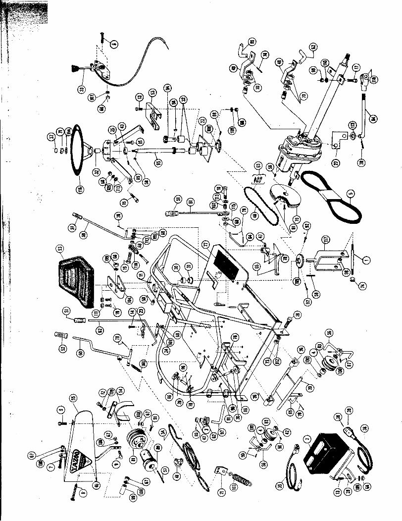
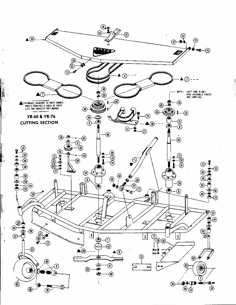
YR-60 & YR- 76 Parts List Cutting Section
No. Part No. Descri tion No. Part No. Descri tion
v('1I 101-003 Adaptor, Blade, Left Hand 30 .. 704-297 Guard Belt YR-60-2 .. 102-024 Arm, Cutting Section, YR-60 30 .. 704-298 Guard Belt YR-762 .. 102-047 Arm, Cutting Section, YR-76 31 704-320 Guard, Rear 603 103-095 Axle, Cutting Section, Rear 32 704-322 Guard, Rear 764 204-020 Bearing, Idler 33 .. 804-058 Hood, YR-605 204-060 Bearing, Hub 33 .. 804-059 Hood, YR-766 204-076 Bearing, Cut. Sec. Wheel 34 806-017 'rfousing, Steel Hub7 .. 205-310 Belt, Blade Drive, YR-76 35 1102-001 Key, 3/16 x 3/16 x 18 ... 205-356 Belt, Wing Drive, YR-60 36 1401-013 Nut, 5/16-188 .. 205-367 Belt, Wing Drive, YR-76 37 1401-020 Nut, 5/16-187 .. 205-395 Belt, Blade Drive, YR-60 38 1401-070 Nut, 5/8-18 Jam9 A 206-760 Blade, YR-60 Offset 39 1401-072 Nut, 5/8-18 Lock9 A 206-776 Blade, YR-76 Offset /40 1401-073 Nut, 5/8-18 L.H. Full
10 208-021 801t, 1/4 x 3/4 AH 41 1608-091 Pulley, Wing Dr. 5 1/40.0. x 3/44 Ga.11 209-051 801t, 1/4-20 x 2 42 1608-092 Pulley, Wing Hub, Left & Right12 209-108 Bolt, 5/16-18 x 3/4 HH 4"5/80.0. x 3/4 S.G.
! 13 209-114 801t, 5/16-18 x 1 HH 43 1-608-201 Pulley, Idler, 2 3/40.0. S.G.
14 209-120 801t, Hub 5/16-18 x 1 1/4 HH 44 1806.001 Ring "0"15 209-126 80lt, Hub & Guide 5/16-18 x 1 1/2 45 1901-006 Screw, Set, 5/16-18 x 1/4 A. H.
HH (2 Aeq'd.) 1..,"46 1904-040 Shaft, Hub16 209-314 B:)' 3/8-16 x 1 HH ,.- 47 1906-006 Shield, Dust,
\ 17 209-617 80!(, 5/8-18 x 1 1/2 HH 48 1906-015 Shield, Cut. Sec. Wheel: 18 209-666 Bolt, (Front Caster Wheel) 49 1913-055 Spacer, 3/4 x 1/2: 5/8-18 x 53/8 50 1913-057 Spacer, 3/4 x 1
19 212-005 801t, 3/8 x 3/8 Stripper 51 1913-110 Spacer, 3/4 1.0. x 1 1/80.0. x 1 7/3220 214-102 Bracket, Tension 52 2301-004 Washer, 5/16 Lock21 214-212 Bracket, Cutting Section Lift 53 2301-006 Washer, 3/8 Lock22 214-213 Bracket, Chute 54 2301-011 Washer, 5/8 Star Lock23 215-009 Bushing, Cutt. Sect. Wheel Yoke 55 2301-012 Washer, 5/8 L.H. Lock24 215-025 Bushing, Spanner 56 2301-021 Washer, 5/16 Flat25 306-011 Chute, Disc 60 & 76 57 2301-022 Washer, 3/8 Flat26 311-002 Collar, 5/8 Set 58 2301-028 Washer, Flat 1 3/8 O.p.x 3/4 1.0.27 502-004 End, Cutting Section Arm 59 2301;081 Washer, 3/4 x 1 114 #18 Ga.28 603-004 Fitting, Grease 60 2301-090 Washer, 5/8 Cupped Spring Blade29 A 704-004 Guard, Right Front, YA-60 61 2301-096 Washer, 5/8 Cupped Spring Blade29 A 704-005 Guard, Left Front, YA-60 62 2302-004 Wheel, 5 x 1.75 Rear29 A 704-181 Guard, Front, Left Side YA-76 63 2302-078 Wheel, Ass'y. Complete, Front29 .A. 704-182 Guard, Front, Right Side YA-76 64 2501-021 Yoke, Front Wheel Mounting
65 2501-028 Yoke, Rear Wheel
316-062 Cutting Section, Complete YA-60- 316-077 Cutting Section, Complete YA-76
WARNING
DO NOT OPERATE A~Y YAZOO PIECE OF EQUIPMENTWITHOUT FIRST READING AND UNDERSTANDING THIS MANUAL.
y~ZOORI CO P ~ arv I u C p, O. BOX 4449/ 3607 LIVINGSTON ROAD
MANUFACTU NG M An II. n . PHONE: (601) 366-6421/ JACKSON, MISSISSIPPI 39216
I
~---~ @~=7~~ - @
¥- @
~~~I.I:> J ~ -@
@@~
@~,:k --
,,
i~:~ AND RI~T~.c ASSEMBLY PARTS\: O~TICAL
,,! i .(~IANGlE) ADJACENT TO PARTS "lMER ~ n 35 '*'-14i}\PREFIX REQUIRES A CHECK OF PARTS ~ 55 -- ~II ST ~ CG4PlETE PART ,...8ER I
--YR.60 & YR.76
CUTTING SECTION
I~.-.@~-@~~ @---V
~ ~-@ ~:;
@-@ ~~~ @~(cC@7@--'1'@ ~ !
:i"
i I. ~-CD
/' ~-@ /i ~~~:~ / @-I @~-@ ~~-r, ~-@ / ~ /I I. ~..C{I:I- ~ .
@ (jj)-I ~~ ~
--

YR-42, 48, 60, & YR- 76 ChassisNo. Part No. Descri tion No. Part No. Description
1 103-020 Axle, Rear Wheel 67 12U1-006 Lever, Blade Engaging2 203-003 Battery 68 . 1201-007 Lever, Clutch, YR-42, 48 & 60
("3') 204-019 Bearing, Ball 68.1201-016 Lever, Clutch, YR-764 204-020 BeariQg, Ball 69 1201-008 Lever, Cutt. Sect. Lift5 . 205-070 Belt, Trans. Dr . I YR-42 & YR-48 ! 70 1201-036 Lever, Clutch5 . 205-071 Belt, Trans. Dr. YR-60 & YR-76 71 1204-001 Link, #41 Master Chain6 208-002 Bolt, 3/16 x 3/4 RH 72 1205-015 Linkage, Short Clutch7 208-028 Belt, 1/4-20 x 1 3/4 RH 73 1205-016 Linkagel-Long Clutch8 208-032 Bolt, 1/4-20 X 4 RH 74.1302-023 Mount, c:ngine AGND9 209-021 Bolt, 1/4-20 x 3/4 HH 74 A 1302-035 Mount, Engine YR-76
10 209-026 Bolt, 1/4-20 x 1 HH 75 1401-001 Nut, 3/16-2411 209-108 Bolt, 5/16-18 x 3/4 HH 76 1401-010 Nut, 1/4-2012 209-114 Bolt, 5/16-18 x 1 HH 77 1401-020 Nut. 5/16-1813 209-120 Bolt, 5/16-18 x 1 1/4 HH 78 1401-030 Nut 3/8 USS14 209-138 Bolt, 5/16-18 x 2 HH (Specify Full Thread) 79 1401-032 Nut, 3/8-2415 209-326 Bolt, 3/8-16 x 11/2 HH H.T. 80 1401-051 Nut, 1/2-2016 209-350 Bolt, 3/8-16 x 2 1/2 HH 81 1401-070 Nut, 5/8-18 Jam17 209-391 Bolt, Soc. HD. 3/8 x 3 82 1401-081 Nut, 3/4-16 Lock18 209-414 Bolt, 7/16-14 x 3/4 HH (Briggs Belt Guard) 83 1601-001 Pad, Pedal19 209-494 Bolt, 1/2-13 x 3/4 84 1601-003 Pad, Battery (Positive Side)20 209-617 Bolt, 5/8-18 x 11/2 HH 85 1601-004 Pad, Foot21 214-104 Bracket, Idler Mounting 86 1602-011 Pedal, Brake22 .. 214-105 Bracket, Upper Steering (YR-42, YR-48, & YR-60) 87 1604-002 Pin, 3/32 x 1 Cotter22 .. 214-209 Bracket, Ass'y. Upper Steering YR-76 88 1604-003 Pin, 1/8 x 1 Cotter23 214-106 Bracket, Transmission Support 89 1604-013 Pin24 214-108 Bracket, Idler 90 1604-037 Pin, 1/8 x 1 1/4 Cotter25 214-144 Bracket, (adL'.) Lower 91 1604-038 Pin, 3/16 x 1 Cotter26 214-148 Bracket, Hi- 0 Lever Mtng. 92 1604-060 PinrPulley 5/8 x 2 1/427 214-149 Bracket, Plate 93 1608-112 Pul ey, 9' Transmission28 . 214-152 Bracket, Brake Actuating 94 A 1608-130 Pulley, Trans. Dr'
1 BriggS) 29 . 214-153 Bracket, Brake Pedal 94.1608-132 Pulley, Trans. Dr. AGND)30 214-206 Bracket, Ass'y. Battery 94 A 1608-142 P411ey, Trans. Dr. TJD-1
!31 215-022 Bushing, 5/8 I.D. x 13/16 O.D. Cable Roller 95 .1608-135 Pulley, Blade Dr' 1AGND 32 215-101 Bushing, Upper R. Wheel Yoke 95 A 1608-136 Pulley, Blade Dr. Bri~gs)
33 215-102 Bushing, ;_Ullver R. Wheel Yoke 95.1608-143 Pulley, Blade Dr. TJD-1)34 215-103 Steering; Bracket 96 1608-205 Pulley, 3" O.D.S.G. Idler35 217-003 Brake, 5" 97 1608-206 Pulley 31/2" O.D.D.G. Idler36 301-018 Cable, Throttle~Briggs & Stratton 98 1808-103 Rod, Clutch Engaging37 301-030 Cable, Cutting ~ection Lift 99 . 1808-179 Rod, Brake38 301-057 Cable, Battery ! Negative) 100 1808-180 Rod, Idler Blade39 301-058 Cable Battery Positive) 101 1809-001 Roller, Cable I40 303-015 Cap, Steering Wheel 102 1901-005 Screw, 5/16-18 x 1/4 A. Hd. Set41 A 303-016 Cap, Battery Red 103 1901-006 Screw, 5/16-18 x 1/4 A. Hd. Set41 . 303-017 Cap, Battery Black 104 1901-009 Screw, 5/16-18 x 5/16 A. Hd. Set42 305-045 Chain, #41 Steering 105 1901-033 Screw, 5/16-18 x 3/4 Sq. Hd. Set43 307-002 Clamp, Cutt. Sect. Lift Cable 106 1901-034 Screw, 3/8-16 x 3/4 Sq. Hd. Set44 307-004 Clamp, Thrott'le Cable 107 1903-012 Seat45 311-002 Collar, 5/8 Set 108 1904-115 Shaft,lntermediateSteering46 311-003 Collar, 3/4 Set 109 1904-116 Shaft, Ass'y. Steering47 401-002 Decal, YAZOO MASTER MOWER 110 1904-152 Shaft, Idler Arm48 . 401-042 Decal, 42 Inch Cut 111 1913-029 Spacer, Pine 1/4 x 1 7/8 Lon~48.401-048 Decal,48 Inch Cut 112 1913-040 Spacer,Washer5/81.D.x7/80.D.48 . 401-060 Decal, 60 Inch Cut 113 1913-057 Spacer, Axle 3/4 x 1 O.D.x 1 Long48 .401-076 Decal, 76 Inch Cut 114 1916-012 Spring, Cutting Section Lever49 401-080 Decal, Fwd.Neutral-Reverse 115 1916-020 Spring, Clutch Lever50 401-081 Decal, Hi-Lo 116 1916-051 Spring, Cutting Section Lift51 401-082 Decal, Cut 117 1916-053 Brake Spring52 401-097 Decal, Brake Caution 118 1916-080 Spring, Seat53 501-002 Elbow Clutch 119 1917-044 Sprocket, 36 T. Rear Steering54 . 502,011 End, Hi-Lo Selector Band 120 1917-045 §procket, 12T. Front Steering55 . 502-012 End, Clutch End 121 .. 2006-042 Transmission, Compo (YR-42)56 603-004 Fitting, 1/4-28 Self Tapping Grease 121 .2006-060 Transmission, Compo (YR-48, 60 & 76)57 703-001 Grip, 7/8" Handle 122 2301-001 Washer, 3/16 Lock58 703-003 Grip, 1/2" Handle 123 2301-003 Washer, 1/4 Lock59 704-084 Guard, Steeri_n-9-Gear 124 2301-004 Washer, 5/16 Lock60 704-185 Guard, Belt (YR-76W/TJD-1) 125 2301-006 Washer, 3/8 Lock61 704-221 Guard, Transmission Drive Belt 126 2301-008 Washer, 1/2 Lock62 . 704-223 Guard, Belt1 AGND) 127 2301-011 Washer, 5/8 Ext. Star Lock62 A 704-285 Guard, Belt Briggs) 128 2301-021 Washer, 5/16 Flat62 A 704-286 Guard, Belt YR- 76) 129 2301-022 Washer, 3/8 Flat63 705-006 Guide, Belt 130 2301-024 Washer, 1/2 Flat64 1102-002 Key, 1/4x 1/4x 1 131 2301-045 Washer, 5/16x 13/4 Fibre65 "1102-012 Key,1/4x1/4x3 132 2303-008 Wheel,Steering
Eng. Pulley, YR42, 48, & 60 133 2501-004 Yoke, 3/865.1102-024 Key,3/8x3/8x3 134 2501-018 Yoke,Steerin~
Eng. Pulley YR76 135 2501-027 Yoke, Adj. 1970 5/16-18 Threads66 1102-013 Key, 3/16 x 3/4 Woodruff 136 2501-030 Yoke, 3/8""
. Used only with Transmission Brake
y~ZOOMAc :uTT"". C-~D1T NGCOMPANYINC P. o. BOX 4449/3607 LIVINGSTON ROAD" nul;\":.-t uAl. ,. PHONE: (601) 366-6421/ JACKSON, MISSISSIPPI 39216

...
...
~1 ~ ~,~ @
) @:~t::_.~/8" ,
I
})
'@

YR-36, 42, 48, 60 & YR- 76Transaxle Parts List
Ref. No. Part No. Ref. No. Part No. Description
1 VA. 103-090 Axle, Long YR-48, 60 & 76 45 1102-013 Key, Woodruff2 A. 103-091 Axle, Short, YR-48, 60 & 76 46 1102-014 Key, Hypro
/3 A. 103-092 Axle, Long, YR-42 '/47 1207-025 Lock, Ring4 ... 103-093 Axle, Short, YR-36 & 42 48 1401-020 Nut, 5/16-18
5 ... 103-094 Axle, Long, YR-36 49 1401-061 Nut, 7/16 Tapered;c""',,,6 204-037 Ball, Detente 50 1401-071 Nut, 5/8-18 Full ~J!!ic~'
7 204-038 Bearing, Ball 51 1604-035 Pin, 3/8 x 3/4 Dowell ~!Vi8 204-039 Bearing, Diff. Carrior 52 1604-036 Pin, Clutch Retainer ~~~
C',"",~c9 204-040 Bearing, Ball 53 1605-031 Plate, Dil Fill Inspection c;['f':~.:'i"';j.,10 209-108 Bolt, 5/16-18 x 3/4 HH 54 1606-006 Plug, 3/8 Std. Pipe Drain ';c;c":-';,~~"
11 209-114 Bolt, 5/16-18 x 1 HH 55 1606-007 Plug, 1 7/8 Welch ';'~;~":-;;,;~!'0"""""12 209-307 Bolt, 3/8-16 x 3/4 HH 56 1804-011 Retainer, Inner Disc :;~'_::i":~~j{. ," "'-13 209-318 Bolt, 3/8-24 x 1 HH Ht. 57 1804-012 Retainer, Outer Disc ;J~;;ff~::;r~y
.-C' ,'C".~'"14 212-011 Bolt, Spring Retainer 58 1804-014 Retainer, Inspection Plate ~c,:!:;~tfl"!:c.c'"_!",.",15 217-003 Brake, 5" Transmission 59 1804-015 Retainer, Inspection Plate ~ §"c,
16 302-020 Cam, Clutch Dog 60 1806-001 Ring, 3/4" I.D. x 1" O:D. c'. ~
17 302-021 Cam, Clutch Adjustment 61 1806-009 Ring, Snap304-053 Case, Shallow half, use 304-005 with 1606-007 62 A. 1808-t15 aod, High-Low Selector
19 A. 304-054 Case, Deep Half 63 A. 1808-116 Rod, Clutch Engaging20 . 304-055 C~se, Shallow Half, with Transaxle Brake 64. 1808-117 Rod, High-Low Selector Used with Brake21 311-050 Collar, SP"";tor 65 . 1808-118 Rod, F & R Selector, Used with Brake S22 315-001 Cup, Oil _reather 66 1902-010 Seal, Oil
23 403-003 Differential, Complete (Less Gear) /67 1902-012 Seal, Axle
24 404-001 Disc, Outer (16 Required) 68 1902-013 Seal, Control Rod Oil25 404-002 Disc, Inner (14 Required) 69 1904-153 Shaft, Clutch ~
26 701-021 Gasket, Inspection Plate 70 A. 1904-154 Shaft, Primary Drive "
27 701-022 Gasket, Axle Housing 71 A. 1904-159 Shaft, Intermediate, Used with Brake :-~;
28 A. 701-026 Gasket,.Transmission Housing 72 1912-020 Sleeve, Clutch ~
29 702-050 Gear, Reverse 73 1912-024 Sleeve, Clutch, Short r(,~~
30 702-051 Gear, High-Low Shift 74 1912-025 Sleeve, Intermediate, Long31 702-052 Gear, Differential Drive 75 1913-034 Spacer, Differential c~:,ry;?" '
32 702-053 Gear, Intermediate Drive 76 1916-013 Spring, Detente :r:;,~~i;;
33 702-054 Gear, Differential 77 1916-054 Spring, Clutch Adjusting c,i;;;;;;-~j,,'-":-34 702-057 Gear, Primary Dri~e 78 2301-004 Washer, 5/16 Lock ~%::~~i~~,
35 702-058 Gear, Forward Drive 79 2301-005 Washer, 5/16 Ext. Star Lock h;",;~~;:,~::;;,-, ",'-
36 A. 806-130 Housing, Axle, Long, YR-48, 60 & 76 80 2301-006 Washer, 3/8 Lock ~~;;':;~1(:c"",-"';i ,37 A. 806-131 Housing, Axle, Short, YR-48, 60 & 76 81 2301-014 Washer, 3/8 Int. Star Lock J,~,~,,~'::;;;-:1;:'!...
c,',,-,..., ,38 A. 806-132 Housing, Axle, Long, YR-42 82 2301-096 Washer, 5/8 Cupped Spring :{:~;!~;;:~;;1;;;~,,;06 33 H . Sh YR 36 ~""",.c_, :;;,;), 39 A. 8 -1 ouslng, ort, . '"':';::;{':',::"'I;;
40 ... 806-134 Housing, Axle, Long, YR-36 310-020 Clutch, Complete ~;'C;i::~,f"i;:;:,,;,41 A. 806-135 Housing, Axl!!, Short, YR-36 2006-036 Transaxle, Complete, YR-36 '0'
42 ... 806-136 Housing, Axle, Short, YR-42 2006-042 Transaxle, Complete, YR-4243 A. 807-036 Hub, Rider Drive Wheel 2006-045 Transaxle W/brake YR-4244 1101-001 Keeper, 2 Halves 2006-060 Transaxle, Complete, YR-48, 60 & 76
2006-065 Transaxle W/brake, YR-48, 60 & 76:';:,'
. Used only with TransmIssion Brake
y~ZOO I'
p, O. BOX 4449/3607 LIVINGSTON ROADMANUFACTURING COMPA.'Nf.INC. PHONE: (601) 366-6421 /JACKSON. MISSISSIPPI 38218 ~
- c C ,~"

-
~~ ".-~ I'~ , '
! = ' " I
~ @~. ~~ :~ -~ " C> s
! S @ ~~",.."" G
~ ~'" s~
a i ~~:1 @~\:'\~"~~ 0 H~ ~C ~ \ ~ - ~ ,-- ~
~ ~- ,I ., t;;'\ ~ t ,0- -- ' C ~ ~ - .-- e Ii" \ ~ - .. I ~'~ ~ @-t§j -', 0 -~~ ~ ~ ~- \:;)
,1 ~;§11--@ 0.,.,- -~ - 0 - -,.'~ ~~ (;) 4 I I "
~ ~~ Y I...=J I I~ Ii'---@!@-- & ~---~~-~~ @ ~,.@ , ~l' Y -~ &~ @ ~---@ '4 @-~:~ r- ~ e- .. """" ~
@) c: --~ ~...J
I J~~~ ~ (i)~ Q ~ ~ ~-@ I .r@ ~ 'I I
; \ ~ ~--- \ \::) , 0 ~ \ .~ @ @- -~ U
@-- ~ I ~,~ ", I.~ @-~~iiJ : @-~~:.;1 . I\ ,.-I1.=- . I
~r--@ -~~ Iie-'~ @'}~~: @- e ~~ "1i ~ ~ '4 ~- ~
~I i @-~::::g~:I @ t:§:{.. ..., @-lrI1 @ @- ~; t1 @--J-
1- @ ~Gi ~
!I @ @ @ ~
.
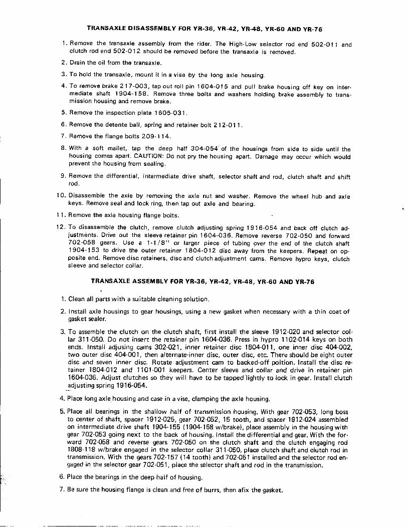
TRANSAXLE DISASSEMBLY FOR YR-36, YR-42, YR-48, YR-60 AND YR-76
1. Remove the transaxle assembly from the rider. The High-Low selector rod end 502-011 andclutch rod end 502-012 should be removed before the transaxle is removed.
2. Drain the oil from the transaxle.
3. To hold the transaxle, mount it in a vise by the long axle housing.
4. To remove brake 217-003, tap out roll pin 1604-015 and pull brake housing off key on inter-mediate shaft 1904-158. Remove three bolts and washers holding brake assembly to trans-mission housing and remove brake.
5. Remove the inspection plate 1605-031.
6. Remove the detente ball, spring and retainer bolt 212-011.
7. Remove the flange bolts 209-114.
8. With a soft mallet, tap the deep half 304-054 of the housings from side to side until thehousing comes apart. CAUTION: Do not pry the housing apart. Damage may occur which wouldprevent the housing from sealing.
9. Remove the differential, intermediate drive shaft, selector shaft and rod, clutch shaft and shiftrod.
10. Disassemble the axle by removing the axle nut and washer. Remove the wheel hub and axlekeys. Remove seal and rock ring, then tap out axle and bearing. .
11. Remove the axle housing flange bolts.
12. To disassemble the clutch, remove clutch adjusting spring 1916-054 and back off clutch ad-justments. Drive out the sleeve retainer pin 1604-036. Remove reverse 702-050 and forward702-058 gears. Use a 1-1/8" or larger piece of tubing over the end of the clutch shaft1904-1. 53 to drive the outer retainer 1804-012 disc away f~om the keepers. Repe.at on op-posite end. Remove disc retainefs, disc and clutch adjustment cams. Remove hypro keys, clutchsleeve and selector collar.
TRANS AXLE ASSEMBLY FOR YR-36, YR-42, YR-48, YR-60 AND YR-76
1. Clean all parts with a suitable cleaning solution.
2. Install axle housings to gear housings, using a new gasket when necessary with a thin coat ofgasket sealer.
3. To assemble the clutch on the clutch shaft, first install the sleeve 1912-020 and selector col-lar 311-050. Do not insert the retainer pin 1604-036. Press in hypro 1102-014 keys on bothends. Install adjusing cams 302-021, inner retainer disc 1804-011, one inner disc 404-002,two outer disc 404-001, then alternate-inner disc, outer disc, etc. There should be eight outerdisc and seven inner disc. Rotate adjustment cam to backed-off poition. Install the disc re-tainer 1804-012 and 1101-001 keepers. Center sleeve and collar and drive in retainer pin1604-036. Adjust clutches so they will have to be tapped 'lightly to lock in gear. Install clutchadjusting spring 1916-054.
4. Place long axle housing and case in a vise, clamping the axle housing.
5. Place all bearings in the shallow half of transmission housing. With gear 702-053, long bossto center of shaft, spacer 1912-025, gear 702-052, 15 tooth, and spacer 1912-024 assembledon intermediate drive shaft 1904-155 (1904-158 w/brake), place assembly in the housing withgear 702-053 going next to the back of housing. Install the differential and gear. With the for-ward 702-058 and reverse gears 702-050 on the clutch shaft and the clutch engaging rod1808-118 w/brake engaged in the selector collar 311-050, place clutch shaft and clutch rod intransmission. With the gears 702-157 (14 tooth) and 702-051 installed and the selector rod en-gaged in the selector gear 702-051, place the selector shaft and rod in the transmission.
6. Place the bearings in the deep half of housing.
7. Be sure the housing flange is clean and free of burrs, then afix the gasket.
- -- --~--- - ---

-~-
8. Put the housings together. Be sure all shafts and shifter rods are started in their respective ~"':"~~i;~bearings before forcing the housing together. :.fi,';J;
9. Drive in the locating dowels at the top and bottom of transmission. Fasten the housing to- :I
gether with the flange bolts.
10. Install inspection covers, oil level plug, breather, shifter ball, spring, and retainer bolt. 0"::1O~,;+;;::~
11. Install axles in place, tap in axle bearings and retainer snap rings. ~":};,:£'i',,;;f,;~
12. Install the axle seal using a thin coat of gasket sealer. c,~;i;{~j..:,,};!.~~13. Install axle keys and wheel hubs. Use generous amount of sealer around the axle threads. In- : ,,';tG;;: C
,., stall washer and axle nut. Tighten the axle nut to 100 ft. Ibs. torque. ;"":ff~",c'?c:;;. '
14. Fill with the proper amount of SAE No. 30 Lub. Oil. (i:,!ff;::"
:':'c;,~~15. The clutch may need readjusting after the transmission is installed. ~o::;:t:;:
TROUBLE SHOOTING THE RIDER TRANSMISSION ~!fj'!";'lo:~"~,,~c.f;:.;
. :;;':l::;ift~.1.011 Leaks: ':"';.;;"
A. Check oil level. Excessive oil may cause leaks. ~:~~::-;;~" ,B. Leak inside wheel at end of axle housing. . Ej,g'fftf.;~'/,c".,'
1 . Check seal surface on hub for damage. :~;:;::;2. Check seal for wear or damage. Replace if necessary using a thin coat of permatex on ,,-'!;;:~f~i-
:C~:~,/"outside of seal. ';:'::,;i"'"',"'"
C. Outside of wheel at axle nut. ",,~!t;;,-'.c-.",
1 . Remove axle nut and washer. Degrease thoroughly. Be sure oil does not seep out on ;~!;I~i;cleaned surface. Apply a generous amount of permatex to both sides of the washer and -'-"'f;;!'c' .axle. Replace the axle nut and tighten to 1 00 ft. Ibs. torque. J¥}¥~
. ,," ~~D. Input shaft and shlfter shafts. 7 "~
1 . Check shaft for burrs or damage. c:.i;~2. Check seals for damage. Replace seals if necessary using a thin coat of permatex on i,,?~
I ccc~'I outside of seal. ';::;~~j, E. Axle flange at transmission. '.~;;i;-';:~: 1. Loose bolts. -:~~;)~:;~
2. Damaged gasket. Replace if damaged. ,":,c'~-"':6;'.'~"'cc+
F. Housing bolt flange. ,i:occ.!)iti':" '"1. Flange damaged. Remove burrs and reseal. ::<::"~',j7;"
! II. W~~'~I~:~~O:~:~~ba:11s .
1. Clutch adjusted improperly. Adjust clutch. ":7}';?;':;"~'c'i",,~.'::;)B. Hi-Low shifter shaft :,i~[;~~@~li~~"*$J;~;~'!.;;'1 . Detente ball and sprin g installed improperly or missing. 'l£~:;,'~Jtk;X~~.'-" .
A ,4,~Jc,.',.'_"',
2. Shift lever hitting frame or steering shaft before gears are fully engaged. Q¥iJ~:~~}ft~f~,~i:,~',","'"""o",3. Spring shift lever to allow transmission to shift properly. ;;:;:",;,~~~;~'::£~~'~:"
, ;.;"f*~;;ol~:cI III. Won t Pull !:~-!,':t~:¥-
"C'-'"'"~' "
! A. Clutch adjusted improperly. Adjust clutch.B. H i- Low I ever between gears. Put in gear.C. Axle key sheared. Replace keys.D. Loose Belt. Tighten Belt.E. Damaged gears or clutch. Replace.
. F. Broken axle. Replace axle. ~'::;:;"
1 I ~~it~
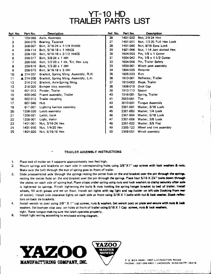
YT-10 HDTRAILER PARTS LIST
Ref. No. Part No. Descri tion Ref. No. Part No. Descri 'on1 103-080 Axle, Assembly 26 1401-032 Nut, 3/8-24 Hex2 204-075 Bearing, Tapered 27 1401-051 Nut, 1/2-20 Full Hex Lock3 208-007 Bolt, 3/16-24 x 1-1/4 RHMS 28 1401-065 Nut, 9/16 Esna Lock4 209-114 Bolt, 5/16-18 x 1 HHCS 29 1401-096 Nut, 1-14 Jam slotted Hex5 209-150 Bolt, 5/16-18 x 2-1/2 HHCS 30 1604-003 Pin, 1/8 x 1 Cotter6 209-317 Bolt, 3/8-24 x 1 HH 31 1604-042 Pin, 1/8 x 1-1/2 Cotter7 209-500 Bolt, 1/2-20 x 1 Ht. Trt. Hex Lug 32 1604-056 Pin, Trailer Safety8 209-518 Bolt, 1/2-20 x 1 HH 33 1609-001 Winch post assembly9 209-575 Bolt, 9/16-18 x 3 HH 34 1804-025 Retainer
10 ... 214-207 Bracket, Spring Mtng. Assembly, R.H. 35 1805-023 Rim11 ... 214-208 Bracket, Spring Mtng. Assembly, L.H. 36 1813-001 Reflector, Trailer12 214-210 Bracket, Axle-Spring Mtng. 37 1813-002 Rope, Trailer13 216-005 Bumper stop assembly 38 1906-010 Dust Cap14 601-013 Fender, Trailer 39 1913-113 Spacer15 605-040 Frame assembly, Trailer 40 1916-081 Spring, Trailer16 802-013 Trailer coupling 41 2003-061 Tire17 807-040 Hub 43 2010-001 Tongue Assembly \
:19 811-001 Lighting harness assembly 44 2301-001 Washer, 3/16 Lock i20 1208-020 Latch assembly 45 2301-003 Washer, 1/4 Lock21 1208-021 Latch, hook 46 2301-004 Washer, 5/16 Lock '1
22 1209-001 Lig~t, trailer 47 2301-006 Washer, 3/8 Lock23 1401-001 Nut, 3/16-24 Hex 48 2301-022 Washer, 3/8 Flat24 1401-010 Nut, 1/4-20 Hex 49 2305-122 Wheel and tire assembly25 1401-020 Nut, 5/16-18 Hex 50 2308-001 Winch assembly
. TRAILER ASSEMBLY INSTRUCTIONS
1. Place bed of trailer on 4 supports approximately two feet high.2. Mount springs and brackets on each side in corresponding holes using J/B"X1" cap screWi with I~ wMhen &, 00tI.
Make sure the bolt through the eye of spring goes to front of trailer.3. Slide preassembled axle through the springs resting the center hole on the eM bracket over the pin m~ the ..,..
resting the center hole on the end bracket over the pin through the sprin~. PI8Ce four 5/16 X 2~" boIti down th~the plates on each side of spring leaf. Place straps under spring u$ing nun and loat washers to clamp ~""Y aft8r uteis tightened to springs. Finish tightening the bolts & nun holdi"i the spring hanger bracket to b«f of trailer. InIt8Ilwheels, fill with grease and set on floor. Install tail lights with ~ li~t aoo tag holder on left side (looking frcxn r8arof trailer). Install side clearance lights on each side at front using 3/16 X 1 boIti with nut 81 I~ waher. St8:k reftec.tors on back tie brackets.
4. I nstall wench to post using 3/8" X 1" cap screws, nuts 81 washers. Set wench post on pta.. ~ .aArw with 1MItI. 1-washers. Set bumper stop assy. on holes at front of tr8iler usi"i 5/16 X 1 Cap ~rews, nUti. ,~ W.IiI..tight. Raise tongue making sure the latch operates properly.
6. Install light wiring according to enclosed wiring diagr8m.
. y~ZOOPOBOX 4449/3607 LIVINGSTON ROAD
KANUFACTURING tOMPANY, INC. ?HONE (60113666421/ JACKSON. MISSISSIPPI 39216
l

- !i «..,j .~
'r..::. fi!
\ I" I I I (
/ (,
/ / (
(
Il' (
III
/ I (
/ ,
( / ,
( (/
( (((
/ ( ,
III
I ((
I I ,
( I (
I I I
/ / I
I I
, I /
I ( 1
I ( ,
I
( I I
( I ( . / , (
1'/(
/ (
I
[!J
!
~~
~ m -~
1&1 ~
= ~ /J I i
~ I ~ ' ~
! ~ ~~- \ / ~!
,i ~ r-
lll @ -t. Ii
I . ~. ~~
OJ" ~ i~ > ~::
~o
~

25 MAINTENANCE TIPS
CHECK LIST TO AID IN REPAIRING & MAINTAINING VAZOO RIDING MOWERS
1\. I nspect seat for looseness or breakage,
2. Inspect rear steering fork bushing for grease and wear.
3. Inspect rear wheel bearing for grease, hand pack.
4. Inspect steering chain for alignment and looseness, lubricate.
5. Inspect steering wheel bushings on upper and lower steering post, oil.
6. Inspect battery for water, clean and tighten cables, see that battery is properly held in place.
7. Inspect blade engaging lever, yoke, nuts and rod. Adjust blade belt bracket so that lower arm-locks snugly against the forward part of the frame when the blades are in the engaged posi-tion.
, 8. Inspect clutch lever, linkage, test clutch for over center lock in, adjust if needed.
9. Inspect High-low shift lever linkage, tighten lever by drawing bolt down through threaded frameand draw nut and lock washer up to it.
10. Inspect brake shoe~, adjust brake rod or replace brake assembly if required. . .11. Inspect drive tires, wheel nuts, axle nuts, adjust air pressure, add sealer or tubes if needed.
12. Inspect transaxle oil level, if low examine drive wheels. Oil on inside of w:'eel indicates leakyseal. Replace, use Permatex on outside of seals. Oil on outside of wheel indicates seepage
f
around axle through hub. Remove, clean and permatex key' ways and threads liberally beforereplacing.
13. Inspect transaxle pulley for looseness.
14. Inspect transmission belt for wear and looseness! lubricate upper idler arm shaft and 2 setscrews. Use care in loosening set screws. They twist off easy on used equipment.
15. Inspect primary blade drive belts for wear, alignment and tension, belts can be tightened bymoving cutting head forward, extend arm end (502-004) equally,
16. Inspect wing belts for wear, alignment of idler pulleys and tension. Idler pulleys should be oninside of V belts.
17. Inspect all belt guards (5) for sharp edges, clearance and damage. Are guards covering beltbacks? Do they clear belts when belts are engaged?
18. Inspect arms, arm ends, and lock nuts.
19. Inspect blade,s for sharpness, balance and to be sure they are on the adaptor all the way.
20. Inspect blades, pulleys, keyways and nuts for wear or looseness. Do this by raising the head,take a blade in each hand and use a back and forth motion to locate looseness and wear. "
21. Inspect yokes, caster, spacers, "0" rings and bushings. Large washers must be next to "0"ring to prevent bottom spa~er from wearing on bushing, also to keep grease in and dirt out.
22. Inspect engine air cleaner to be sure it is clean and functioning right.
23. Inspect crank case oil for proper grade and type. Change every 20 hours or as per enginemanual.
24. Inspe.ct gas tank and filter system. Use right grade of gas, Refer to engine book.
25. Inspect intake screen and shroud. Remove if necessary and clean.

IIi
i 1.
~,t
GENERAL SAFETY RULES
t 1. Know your controls. Read the owner's manual carefully. Learn how to stop
; engine quickly in emergency.I : 2. Make sure the lawn is clear of sticks, stones, wire and debris - they could be
I thrown by the blade.
j 3. Never add ~uel to a running engine. Use an approved safety container and
remember that gasoline is a hazard to your home.
4. Keep children and pets at a good, safe distance away.
5. Disengage clutches and shift into neutral before starting motor.
6. Start the engine carefully. . . keep feet well away from the blades when starting
and running.
i 7. Do not operate engine where carbon monoxide fumes can collect.i! 8. Stop the engine whenever you leave the mower, even for a moment.
( 9. Always properly maintain the mower, frequently checking all fasteners, guards andparts. Follow manufacturer's maintenance and storage instructions.
,;: 10. Clear the area before driving mower across drives, walks, or roads.
11. Do not allow any adult to operate mower without instruction. ~ allow children
to operate a mower.
12. On slopes or wet grass, be extra careful of your footing. Do not operate on slopes0 .
exceeding 15 angle of bank.
13. Stop the engine and disconnect spark wire before checking or working on the
mower.
14. Never use a plug-in electric mower in the rain or when grass is wet.
15. Never leave a starter in cocked position. This refers to starters using a heavy
spring which is crank wound and then released for starting.
16. Do not overspeed the engine or alter governor settings. Excessive speed is dangerous
and shortens mower life.
17. Keep all shields and safety devices in place, as instructed in owner's manual.
18. Do not cut at night or times of low visibility.
SOME WINTER STORAGE TIPS:
i 1. Drain all gasoline from the tank, start the engine ,3nd run until fuel lines and carburetor are free of
! fuel. Gasoline left in the engine or tank will eV8fjOrate and leave varnish and gum which may clog
1 small openings.. 2. Remove the carburetor bowl, clean thoroughly and replace. Remove the spark plug and pour one
teaspoon of SAE 10 - weight motor oil into the cylinder. Crank the engine several times to dis-I tribute the oil; stop the cylinder at the top of the stroke and replace the spark plug. This smalli amount of oil prevents rust and keeps the piston from sticking to the cylinder wall.i 3. Clean the outside of the engine, including the cooling fins on the cylinder and head. Service the! air cleaner. Coat all unpainted metal parts with grease or oil and disconnect the spark plug lead.
! I 4. For four-cycle engines, drain the crankcase and leave it empty unless there is a chance of an un-
i 1 authorized person adding fuel and starting the engine., I, j 5. Store the Yazoo inside a building if possible. If the motor must be left in the open, cover the
engi ne with a waterproof fabric or plastic to protect it from weather.
6. Thoroughly clean all frame surfaces and apply the respective YAZOO paint to surfaces needingtouching up. If paint is not utilized, a thin oil coating on exposed areas will ward off rust, etc.
! 7. Make sure tires are aired to prescribed levels as set forth in your Yazoo Owner's Manual.
I ! 8. Pack rear wheel bearings on Yazoo Big Wheel Mowers with a good grade of axle grease, and adjust.
,I I

807-038 1 "'1401--- 312-007 ~204-034 '"
1902-005---; 7 ~ :~~=--- --I) f) {j)-- ~
0;
(~-y--- )808-123
\.1805--- \*(optional) £2003---
, - -
A (Tria1gle) adjacent to Parts Number PREFIX requires a check of Parts List for complete Parts No.* Optional Parts
.. ~
204-034 Bearing, Cone, 3/4 Tapered Roller312-008 Cone, Bearing Race807-036 Hub, Drive807-038 Hub, 5-bolt Steering808-123 Hub Ass'y., Steering Complete
.1401-057 Nut, 1/2-20 Tapered Lug1401-061 7/16 Tapered Lug Nut
.1805-007 Rim, 5-Hole, 650 X 8 (YR-36, YR-42, & Rear YR-48, YR-60 & YR-76)
.1805-008 Rim, 5-Hole, 950 X 8 (YR-48, YR-60, & YR-76 Front)
1902-005 Seal, Oil&2003-054 Tire, Traction, 650 X 8 2 Ply (YR-36, YR-42, & Rear YR-48, YR-60 & YR-76).2003-058 Tire, Xtra Traction, 950 X 8 2 Ply (YR-48, YR-69 & YR.76 Front)
-2005-054 Tube, 650 X 8-2005-055 Tube, 950 X 8
2305-018 Tire Ass'y., 16 X 650 X 8 Tubeless (YR-36, YR-42 & Rear YR-48, YR-60 & YR-76)2305-022 Tire Ass'y., 18 X 950 X 8 Tubeless (Front YR-48, YR-60 & YR-76)

!,I Q
""" G)BI II OF MAT ERIAL ' ,;;,." ,,~, ~'."'""C!"'~""'~ ~ /' . ~,",;;"i;;'Jt';;~",,)1it),~"4 ~QI£: C"~-: ,.~Y;::..' ,1. 1 ~ CDM Muffler (1304~002) ,,;;;""'.,"::::;t;~;w, -.::::, 2. 1-1%"Clamp(307-011) 9 ',:::, ,/;;-3. 1 - 1 5/8" Clamp (307-010) \..?J ,-l, '{4. 1 - 1%" x 1" Reducer Ell (503-023) ~ '~-.JII5. 1 -11/4" Short Nipple (503-016) ')/
; 6.1-1"CloseNipple(503-022) 0 I'7. 1 - Exhaust Deflector (408-002) "-A & :1
DIRECTIONS: If1. Remove original Muffler and 8" pipe. Leave original 1" nipple in engine :' '!!!"'~
and 90 degree 1" ell. , ,:2. Screw 1" Close Nipple into original 90 degree 1" ell. '3\ ',; I'3. Screw 1%" x 1" Reducer 90 degree ell on 1" close nipple. "-:::I, ' '- 'I ,:4. Attach Muffler to 1 Y2" Nipple with 1 %" clamp. ~ ,~, ~5. Attach muffler and exhaust deflector to tractor frame by drilling two ~ - '
(2) 5/16" holes in lower frame and secure with 1 5/8" clamp provided. \.>-- 0(Note: Attach exhaust deflector pointing to rear of tractor.)5HIPP/NG WEIGHT -6Ibs. MUFFLER KIT
VR - 48 and VR - 42 BRIGGS AND STRATTON~..'"'.~ ~-_!!!
BILL OF MATERIAL: G) ~--~ ~1. 1-CDMMuffler(1304-001) ~ y ~
2. 1 -1%" Clamp (307-011) ~3. 1 - 1 5/8" Clamp (307-010) n ~,'J()V Q4. 2 - Short 1%" Nipples (503-016) W~ O~~-: 5. 1-5"x1%"Nipple(503-017) ~6. 1 .90 degree Ell 1%" (503-014) ~ . t f"""'\7. 1 - 45 degree Ell 1%" (503-018) ':::::::;, Q.4,.--~V8. 1 . Exhaust Deflector (408-002) "::-.::-_-~~-::--=--=.-=.: '7~~
01 RECTIONS: G) 1;; 11 ":",,.,!
1. Remove original muffler and pipe. \ R\, r! ;Q. Screw 1 %" close nipple into block. ~ :; ;J:;- 3. Screw1%"x45d~gree~llon 1%"closenipple. & ! r1 :: \14. Screwl%"closenlpplelnt045degreeell. . "
1 .'; -,5. Screw1%"x90d~gree.ellon1~"closenipple. ~ 1 :. ~~(6. Screw1%"x5"nlpplelnt01% x 90 degree ell. ,~~.. 'c-7. Attachmufflert05"nippleusing1%"clamp. n "~ I;' C"",;8. Attach muffler and exhaust deflector to tractor frame by drilling two ~ '.; 1...,. ;",; :::; ",' ,
(2) 5/16" holes in lower frame and secure with 1 5/8" clamp provided. "'""~ -~', , ;(Note: Attach exhaust deflector pointing to rear of tractor.) ~-,i~ C. "'=-"-! SHIPPI NG WEIGHT -8 Ibs. " ',-~ '
. MUFFLER KITi VR - 60 AGND WISCONSIN !I ~.,. ~~...~~~... ... --~-"-"'U~,",'.""~ ,; BILL OF MATERIAL: (i), 1.1-11/4"x90degreeEII(503-014) r:\ ~/: 2. 2 - 1%" x 10" Nipple (503-019) \!.J~/)j~ r;-.,
3. 1 - 11/4" Close Nipple (503-020) ~, ~ ~\!.I 4. 1 - 11/4" Cuppler (503-021) ,: 5. 1 - 1 5/8" Clamp (307-010) " --ffG6. 1 - Exhaust Deflector (408-002) '(l"\ r{
~ 'I: DIRECTIONS: I :'' 1. Remove exhaust manifold from engine. t']~G)2. Place in vise and remove original nipple from manifold. ::::Tlr-o=---i: '[ 3. Screw 1 %" Close nipple into manifold. ~ II4. Screw 1 %" x 90 degree ell on close nipple. Draw up as tight as possible. A~~
, 5. Screw 1%" x 10" nipple into 90 degree ell. Eju I: ! 6. Screw 90 degree ell from original muffler on 1 %" x 10" nipple. - I,I 7. Remount manifold on engine. J
8. Screw 1 %" x 10" nipple into 90 degree ell. ~ ::
9. Screw 1 %" coupler on 1 %.. x 10" nipple. "--. Q10. Screw original muffler in 1 %" coupler. ~-11. Attach muffler and exhaust deflector to tractor frame by drilling two p. "
(2) 5/16" holes in lower frame and secure with 1 5/B" clamp provided. \>-- -. 0(Note: Attach exhaust deflector pointing to rear of tractor.)
! SHIPPING WEIGHT-7Ibs. MUFFLER KIT
I VA - 60 TJD & VA. 76 TJD WISC.

r
3
,
/
- - - - -,.. , ~- -
-- '.~
.;;;~ 0\ \0\
Gj.
BI LL OF MATERIAL:
1. Right Half (2304-002)2. Left Half (2304-001)3. 1 - Attaching Bolt 3/8" x 10" (209-395)4. 2 - Flat Washer - 3/8" (2301-022)5. 1 - Nut 3/8" (1401-030)
DIRECTIONS:
1. Position Right Half (No.1) on rear of tractor as shown and startbolt No.3 and washer No.4 through holes in weight to support weight on rear.
2. Position Left Half (No.2) in the same manner as No.1.
3. Secure weights in place with Nut (No.5) and tighten. (Note: Tighten nutuntil weights will not be allowed to swing up and down.)
!i
i
ii!
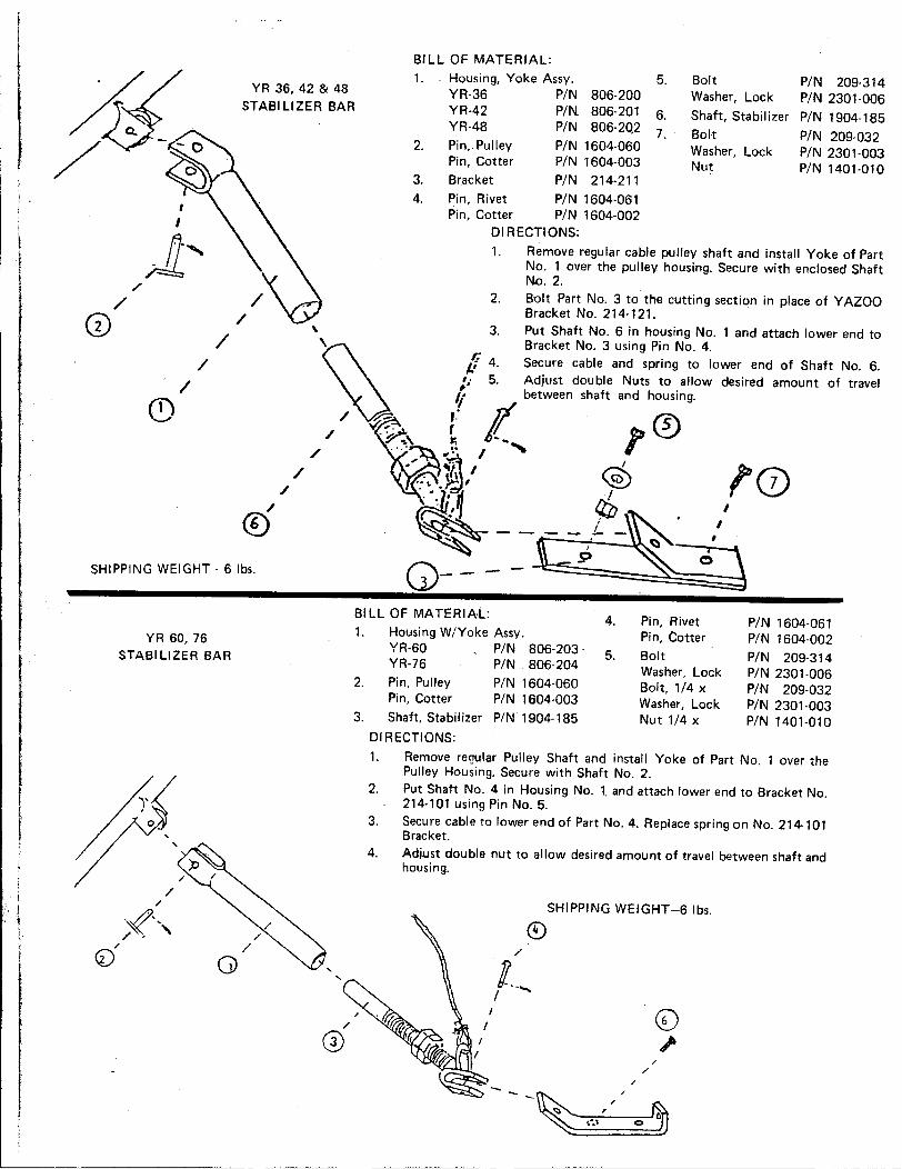
t BILL OF MATERIAL:;jj 1. Housing, Yoke Assy. 5. Bolt PIN 209-314. YR 36, 42 & 48 YR-36 PIN 806-200 Washer, Lock PIN 2301-006
STABILIZER BAR YR-42 PIN 806-201 6. Shaft, Stabilizer PIN 1904-185
Q. YR-48 PIN 806-20,2 7, Bolt PIN 209-032/ 2, Pin, Pulley PIN 1604-060 Washer, Lock PIN 2301-003
Pin, Cotter PIN 1604-003 Nut PIN 1401-010i 3 Bracket PIN 214-211
I ; 4: Pin, Rivet PIN 1604-061j . I Pin, Cotter PIN 1604-002
1 I DIRECTIONS:
I ~ -' 1. Remove regular cable pulley shaft and install Yoke of PartI f - No.1 over the pulley housing. Secure with enclosed Shaft
No.2./' / 2. Bolt Part No.3 to the cutting section in place of Y AlOO/ Bracket No. 214-121.
i G) / 3. Put Shaft No.6 in housing No.1 and attach lower end to
/ \ Bracket No.3 using Pin No.4.
/ ~ f 4. Secure cable and spring to lower end of Shaft No.6.'0' 5. Adjust double Nuts to allow desired amount of travel/ ~ between shaft and housing.
C9 / ~\ :: It 0/ ~\ ~ I -', ,// X~.~/ ~ '0
/ ~.._~~~: -if ~/ "1 !~~~~~::i~" (9 ~~~~~~ - - - - J,L - ~ "
.9 0SHIPPING WEIGHT - 6 Ibs. Q- - - -- -
BILL OF MATERIA.L: 4. Pin, Rivet PIN 1604-0611. Housing W/Yoke Assy. Pin Cotter PIN 1604-002YR 60 76 ,, YR-60 PIN 806-203 5. Bolt PIN 209-314
STABILIZER BAR YR-76 PIN 806-204 Washer, Lock PIN 2301-006
2. Pin, Pulley PIN 1604-060 Bolt, 1/4 x PIN 209-032Pin, Cotter PIN 1604-003 Washer, Lock PIN 2301-003
3. Shaft, Stabilizer PIN 1904-185 Nut 1/4 x PIN 1401-010
DIRECTIONS:1. Remove re!]ular Pulley Shaft and install Yoke of Part No.1 over the
Pulley Housing, Secure with Shaft No.2.~ 2. Put Shaft No.4 in Housing No.1. and attach lower end to Bracket No.
j' 214-101 using Pin No.5. .0 3. Secure cable to lower end of Part No.4. Replace spring on No. 214-101
, Bracket.4. Adjust double nut to allow desired amount of travel between shaft and
housing,
/,. SHIPPING WEIGHT -6 Ibs.
; ;.('" ~, ,. /'I" 0 " i-
I I CD
I @ //..1-
r /- - /- /
':I ,r '~;~~;;;~~~;~~;;~~~;;~~)f
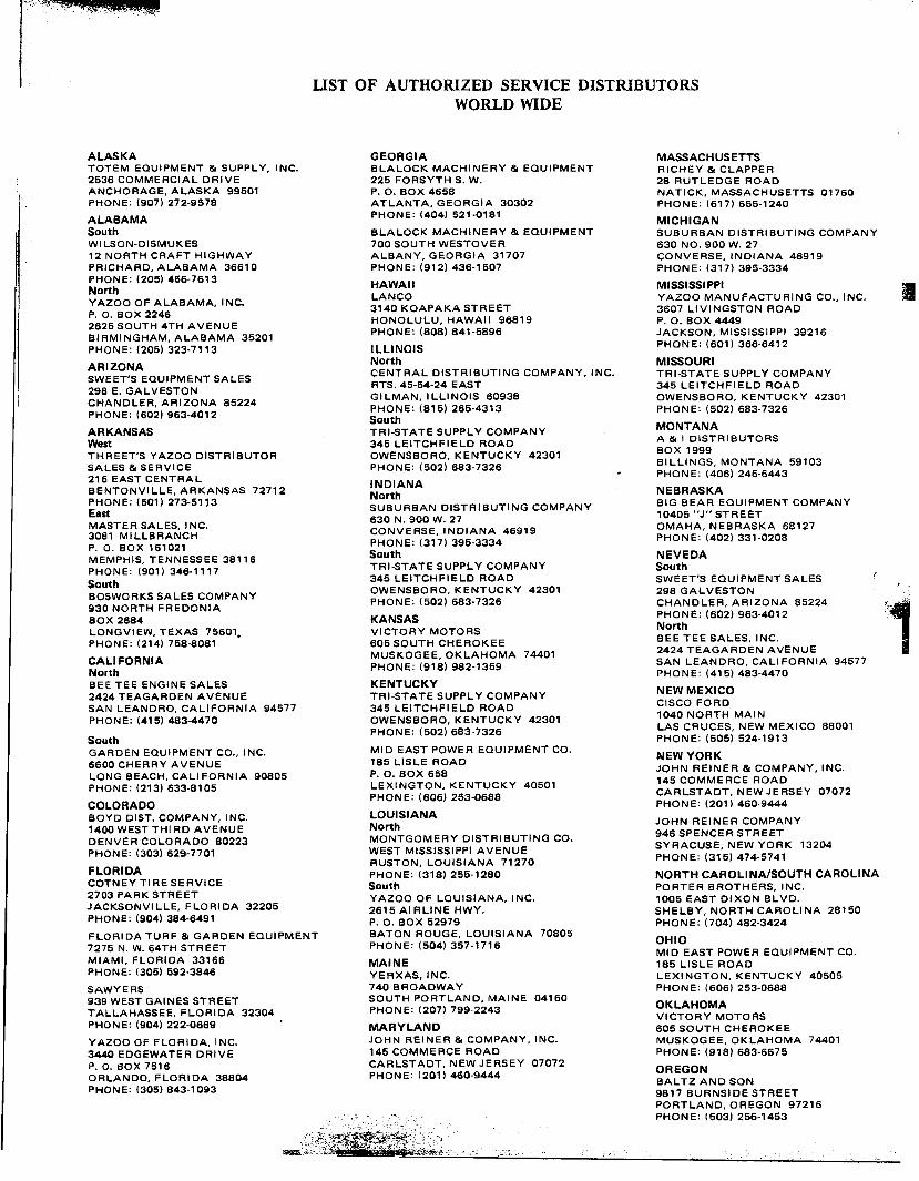
liST OF AUTHORIZED SERVICE DISTRIBUTORSWORLD WIDE
ALASKA GEORGIA MASSACHUSETTSTOTEM EQUIPMENT & SUPPLY, INC. BLALOCK MACHINERY & EQUIPMENT RICHEY & CLAPPER2536 COMMERCIAL DRIVE 225 FORSYTH S. W. 28 RUTLEDGE ROADANCHO.RAGE, ALASKA 99501 P. O. BOX 4658 NATICK, MASSACHUSETTS 01760PHONE. (907) 272-9578 ATLANTA, GEORGIA 30302 PHONE: (617) 655-1240ALABAMA PHONE: (404) 521-0181
MICHIGANSouth BLALOCK MACHINERY & EQUIPMENT SUBURBAN DISTRIBUTING COMPANYWILSON-DISMUKES 700 SOUTH WESTOVER 630 NO. 900 W. 2712 NORTH CRAFT HIGHWAY AL8ANY, GEORGIA 31707 CONVERSE, INDIANA 46919PRICHARD, ALABAMA 36610 PHONE: (912) 436-1507 PHONE: (317) 395-3334PHONE: (205) 456-7613 HAW INorth AI MISSISSIPPIYAZOO OF ALA8AMA, INC. LANCO YAZOO MANUFACTURING CO., INC.P. O. BOX 2246 3140 KOAPAKA STREET 3607 LIVI NGSTON ROAD2625 SOUTH 4TH AVENUE HONOLULU, HAWAII 96819 P. O. BOX 4449BIRMINGHAM, ALA8AMA 35201 PHONE: (808) 841-5896 JACKSON, MISSISSIPPI 39216PHONE: (205) 323-7113 ILLINOIS PHONE: (601) 366-6412
ARIZONA North MISSOURISWEET'S EQUIPMENT SALES CENTRAL DISTRIBUTING COMPANY, INC. TRI-STATE SUPPLY COMPANY298 E. GALVESTON RTS. 45-54-24 EAST 345 LEITCHFIELD ROADCHANDLER, ARIZONA 85224 GILMAN, ILLINOIS 60938 OWENSBORO, KENTUCKY 42301PHONE: (602) 963-4012 PHONE: (815) 265-4313 PHONE: (502) 683-7326
SouthARKANSAS TRI-STATE SUPPLY COMPANY MONTANAWest 345 LEITCHFIELD ROAD A & I DISTRIBUTORSTHREET'S YAZOO DISTRIBUTOR OWENSBORO, KENTUCKY 42301 BOX 1999SALES & SERVICE PHONE: (502) 683-7326 BILLINGS, MONTANA 59103215 EAST CENTRAL - PHONE: (406) 245-6443
INDIANABENTONVILLE, ARKANSAS 72712 N h NEBRASKAPHONE: (501) 273-5113 ortE It SUBURBAN DISTRIBUTING COMPANY BIG BEAR EQUIPMENT COMPANYM~STER SALES INC 630 N. 900 W. 27 10405 "J" STREET3081 MILLBRANCH . CONVERSE, INDIANA 46919 OMAHA, NEBRASKA 68127P. O. BOX 161021 PHONE: (317) 395-3334 PHONE: (402) 331-0208
MEMPHIS, TENNESSEE 38116 South NEVEDAPHONE: (901) 346-1117 TRI-STATE SUPPLY COMPANY SouthSouth 345 LEITCHFIELD ROAD SWEET'S EQUIPMENT SALES (BOSWORKS SALES COMPANY OWENSBORO, KENTUCKY 42301 298 GALVESTON930 NORTH FREDONIA PHONE: (502) 683-7326 CHANDLER, ARIZONA 85224 -.BOX 2684 KANSAS PHONE: (602) 963-4012 '~:
,LONGVIEW, TEXAS 75601. VICTORY MOTORS NorthPHONE: (214) 758-8081 605 SOUTH CHEROKEE BEE TEE SALES, INC.CALIFORNIA MUSKOGEE, OKLAHOMA 74401 2424 TEAGARDEN AVENUEN th PHONE: (918) 982-1359 SAN LEANDRO, CALIFORNIA 94577B~~ TEE ENGINE SALES KENTUCKY PHONE: (415) 483-4470
2424 TEAGARDEN AVENUE TRI-STATE SUPPL Y COMPANY NEW MEXICOSAN LEANDRO, CALIFORNIA 94577 345 LEITCHFIELD ROAD CISCO FORDPHONE: (415) 483-4470 OWENSBORO, KENTUCKY 42301 1040 NORTH MAIN
PHONE: (502) 683.7326 LAS CRUCES, NEW MEXICO 88001South PHONE: (505) 524-1913GARDEN EQUIPMENT CO., INC. MID EAST POWER EQUIPMENT CO. HE Y K6600 CHERRY AVENUE 185 LISLE ROAD W ORLONG 8EACH, CALIFORNIA 90805 P. O. BOX 658 JOHN REINER & COMPANY, INC.PHONE: (213) 633-8105 LEXINGTON, KENTUCKY 40501 145 COMMERCE ROAD
PHONE: (606) 253-0688 CARLSTADT, NEW JERSEY 07072COLORADO PHONE: (201) 460-9444BOYD DIST. COMPANY, INC. LOUISIANA1400 WEST THI RD AVENUE North JOHN REINER COMPANYDENVER COLORADO 80223 MONTGOMERY DISTRIBUTING CO. 946 SPENCER STREETPHONE: (303) 629-7701 WEST MISSISSIPPI AVENUE SYRACUSE, NEW YORK 13204
RUSTON LOUISIANA 71270 PHONE: (315) 474-5741FLORIDA 'COTNEY TIRE SERVICE PHONE: (318) 255-1280 NORTH CAROLINA/SOUTH CAROLINA2703 PARK STREET South PORTER BROTHERS, INC.JACKSONVILLE, FLORIDA 32205 YAZOO OF LOUISIANA, INC. 1005 EAST DIXON BLVD.PHONE: (904) 384-6491 2615 AIRLINE HWY. SHELBY, NORTH CAROLINA 28150
P. O. BOX 52979 PHONE: (704) 482-3424FLORIDA TURF & GARDEN EQUIPMENT BATON ROUGE, LOUISIANA 708057275 N. W. 64TH STREET PHONE: (504) 357-1716 OHIOMIAMI, FLORIDA 33166 I MID EAST POWER EQUIPMENT CO.PHONE: (305) 592-3846 MA NE 185 LISLE ROAD
YERXAS, INC. LEXINGTON, KENTUCKY 40505SAWYERS 740 BROADWAY PHONE: (606) 253-0688939 WEST GAINES STREET SOUTH PORTLAND, MAINE 04160TALLAHASSEE, FLORIDA 32304 PHONE: (207) 799-2243 OKLAHOMAPHONE: (904) 222-0669 VICTORY MOTORS
MARYLAND 606 SOUTH CHEROKEEYAZOO OF FLORIDA, INC. JOHN REINER & COMPANY, INC. MUSKOGEE, OKLAHOMA 744013440 EDGEWATER DRIVE 145 COMMERCE ROAD PHONE: (918) 683-6675P- o. BOX 7516 CARLSTADT, NEW JERSEY 07072ORLANDO, FLORIDA 38804 PHONE: (201) 460-9444 OREGONPHONE: (305) 843-1093 BALTZ AND SON
9817 BURNSIDE STREETPORTLAND, OREGON 97216
-;~ PHONE: (503) 256-1453

. -
,)
WARNING
1. DO NOT EXCEED 15° ANGLE OF BANK .WITH ANY YAZOO MOWER.
2. REMEMBER THESE RULES OF THUMB
IF YOU CAN1T JUDGE 15°.-
A. IF THE MOWER WILL NOT CLIMBIT STRAIGHT ON - STAY OFF IT. ).,
;,I
B. WALK THE AREA IF YOU ARE NOTCOMFORTABLE - THEN STAY OFF
IT.
3. THIS IS A CUTTING MACHINE, RE-
SPECT IT. DO NOT EXCEED ITS LIMI-
. TATIONS.
4. USE COMMON SENSE AND PLENTY OF
IT.