FOR ALLFOR ALL InfinityInfinity - National Gateworks Inc
28
Doc 6001566 Doc 6001566 Doc 6001566 Doc 6001566 Rev D Rev D Rev D Rev D INSTALLATION INSTRUCTIONS INSTALLATION INSTRUCTIONS INSTALLATION INSTRUCTIONS INSTALLATION INSTRUCTIONS FOR ALL FOR ALL FOR ALL FOR ALL Infinity Infinity Infinity Infinity TELEPHONE ENTRY SYSTEMS TELEPHONE ENTRY SYSTEMS TELEPHONE ENTRY SYSTEMS TELEPHONE ENTRY SYSTEMS (EXCEPT THOSE WITH MULTI-LINK FIRMWARE)
Transcript of FOR ALLFOR ALL InfinityInfinity - National Gateworks Inc

Doc 6001566Doc 6001566Doc 6001566Doc 6001566 Rev D Rev D Rev D Rev D
INSTALLATION INSTRUCTIONSINSTALLATION INSTRUCTIONSINSTALLATION INSTRUCTIONSINSTALLATION INSTRUCTIONS FOR ALLFOR ALLFOR ALLFOR ALL
InfinityInfinityInfinityInfinity TELEPHONE ENTRY SYSTEMSTELEPHONE ENTRY SYSTEMSTELEPHONE ENTRY SYSTEMSTELEPHONE ENTRY SYSTEMS (EXCEPT THOSE WITH MULTI-LINK FIRMWARE)


Rev D Doc 6001566
TABLE OF CONTENTS
IMPORTANT NOTICES................................................................................................................. 1
INSTALLATION TIPS.................................................................................................................... 1
PART 1 ARRANGING PHONE LINE INSTALLATION ................................................................ 2
PART 2 MOUNTING THE CABINET............................................................................................ 2
PART 3 WIRING........................................................................................................................... 4
A. TELEPHONE INTERFACE BOARD CONNECTIONS........................................................................ 4 B. PROCESSOR BOARD SIGNAL CONNECTIONS ............................................................................. 5 C. OPTIONAL CCTV CONNECTIONS................................................................................................... 7 D. POWER CONNECTIONS.................................................................................................................. 8 E. POWER ON....................................................................................................................................... 9
PART 4 INSTALLING ADDITIONAL FEATURES ..................................................................... 10
A. POSTAL LOCK INSTALLATION...................................................................................................... 10 B. AUXILIARY OPENING/REQUEST ACCESS DEVICES................................................................... 10 C. DOOR POSITION SENSING........................................................................................................... 10 D. BAUD RATE FOR RS-232 COMMUNICATION ............................................................................... 11 E. HOOKING UP A TERMINAL............................................................................................................ 11 F. HOOKING UP A PRINTER .............................................................................................................. 14 G. HOOKING UP A EXTERNAL MODEM ............................................................................................ 15 H. HOOKING UP REMOTE KEYPADS/KEYPAD LIGHTS................................................................... 16 I. HOOKING UP CARD READERS ...................................................................................................... 17 J. HOOKING UP BUILT-IN MODEM/REMOTE PROGRAMMING/MULTIPLE ENTRY......................... 18 K. HOOKING UP OPTIONAL CCTV..................................................................................................... 18
PART 5 TESTING AND ADJUSTING THE UNIT....................................................................... 19
A. LCD DISPLAY/FAN ......................................................................................................................... 19 B. TELEPHONE ENTRY ...................................................................................................................... 19 C. CARD ENTRY ................................................................................................................................. 21 D. CODE ENTRY ................................................................................................................................. 21 E. POSTAL LOCK, REQUEST FOR ACCESS, DOOR POSITION MONITORING............................... 21 F. BUILT-IN MODEM ........................................................................................................................... 22 G. MULTIPLE ENTRY.......................................................................................................................... 22 H. METHOD OF DIALING.................................................................................................................... 22 I. OPTIONAL CCTV MONITORING...................................................................................................... 22
FCC REQUIREMENTS................................................................................................................ 23
DOC REQUIREMENTS ............................................................................................................... 24

Doc 6001566 Rev D
TABLE OF FIGURES
Figure 1: Mounting the Cabinet .....................................................................................................2 Figure 2: Telephone Interface Board Connections.........................................................................4 Figure 3: Infinity Circuit Board Connections (1100023)..................................................................5 Figure 4: Infinity Circuit Board Connections (1100072 Board) .......................................................6 Figure 5: Optional CCTV Unit ........................................................................................................7 Figure 6: DB25 Connections .......................................................................................................12 Figure 7: DB9S Connections .......................................................................................................13 Figure 8: Hooking Up an External Modem...................................................................................15 Figure 9: Telephone Interface Board, Adjustments and Indicators...............................................20 Figure 10: CCTV Power Supply Board J1 Connector ..................................................................22
COPYRIGHT 2002 ALL RIGHTS RESERVED This document is protected by copyright and may not be copied or adapted without the prior written consent of Sentex. This documentation contains information proprietary to Sentex and such information may not be distributed without the prior written consent of Sentex. The software and firmware included in the Sentex Infinity system as they relate to this documentation are also protected by copyright and contain information proprietary to Sentex. Sentex Systems Chatsworth, CA Visit us at www.sentexsystems.com

Rev D Doc 6001566 Page 1 of 24
IMPORTANT NOTICES The Infinity System is a powerful and flexible access control system, but may be damaged by incorrect installation. In particular, it is critical that Infinity systems be grounded properly. Each system contains static sensitive components that can be destroyed by static discharge if not grounded thoroughly.
WARNING: Incorrect installation invalidates the warranty. Please take the time to read these instructions carefully before attempting installation.
INSTALLATION TIPS The sections that follow contain detailed procedures for each step required to install an Infinity system. In addition, the following installation tips will help ensure your installation is done correctly and efficiently.
1. GROUND THE UNIT. The Infinity contains parts that may be damaged by static discharge. A proper earth ground connected to the upper left grounding screw shown in Figure 3 or Figure 4 will significantly reduce the chances of damage or improper operation. The shielding in the cables for all remote keypads or card readers should be connected to the earth ground at the controller end of the cable only. To be effective, the ground connection must be made by running 12 AWG copper wire to a good ground point (e.g., an electrical panel, a metallic cold water pipe that runs into the earth, or a grounding rod at least 10 feet in length that is driven into the earth) within 12 feet of the unit. Even if you have a good earth ground, you should try to discharge any static before handling the circuit boards. WARNING: Damage caused by static discharge is not covered by warranty. CAUTION: Do not connect the two large heat sinks on the main circuit board together as doing so can damage the power supply.
2. PROVIDE POWER FROM A DEDICATED SOURCE. The outlet(s) into which you plug the Sentex provided transformer or an AC power supply should each be wired to their own circuit breaker. The optional CCTV must be plugged into a separate outlet. This will reduce line noise introduced into system power and minimize the risk of having other equipment interrupt unit operation.
3. DO NOT OVERLOAD THE TERMINAL BLOCKS. The terminal blocks used in the Infinity are removable and the pins are soldered into the boards. To connect your wires, remove the "head" from the correct terminals and open the screws. Insert the wire into the correct opening on the front and tighten the screw until the wire is held snugly. When you have made all connections for a given "head", plug it back onto the pins designated for that terminal block. Do the same for the optional CCTV board.
Stranded wire must be between 16 and 24 AWG. Solid wire must be between 18 and 24 AWG. This is the total thickness measurement so, if you are putting two wires in, the combined thickness must fall within this range. NEVER try to insert more than two wires per terminal.
4. READ THE MARKINGS CAREFULLY. The connection points are marked on the boards clearly. Before making any connections, be sure to read the markings and check it against the corresponding figure in these instructions so that you understand the connection you are making.
5. MOUNT THE UNIT AT THE CORRECT HEIGHT. Mount the Infinity according to local, state, or national regulations (i.e., the Americans with Disabilities Act). If no such regulations apply, mount the "L" series systems with the display center 5 1/2 feet high for walk-up installations and 4 feet high for drive-up installations. Mount "S" series systems slightly lower because the LCD reads better from above.
6. CLEAN THE DISPLAY AND WINDOW: The LCD display, protective lexan window, and the curved window in the “L” series display hood may be coated with an optional anti-glare formula. Dirt seriously reduces this coating's effectiveness, making the display hard to read. Your customer MUST clean these assemblies routinely using a soft rag and mild soap and water. Avoid harsh or abrasive cleaners.
7. TRAIN YOUR CUSTOMER. The Infinity is easy to program and use when you take a few minutes to train the user, but untrained users can cause serious problems for you and for themselves. SPEND THE TIME NOW to train your customer; it will save you both a lot of trouble later.

Page 2 of 24 Doc 6001566 Rev D
PART 1 ARRANGING PHONE LINE INSTALLATION Your customer should have the telephone company install a telephone line as close as possible
to the Infinity system location. • This line can use either tone or rotary dialing. • Rotary lines are cheaper, but tone lines dial faster. • The Infinity is factory-set to tone dial, but can be changed during installation (see Part 5). • When ordering the telephone line, the phone company requires the following information: FCC REGISTRATION NUMBER: DS83E7-1796-ALE RINGER EQUIVALENCE NUMBER (REN): 0.1B TYPE OF CONNECTOR REQUIRED: USOC RJ11C
PART 2 MOUNTING THE CABINET ♦ This manual describes the "L" series (with telephone entry capability and a large display), since
this is the most complicated installation. The unit is shown with optional CCTV. ♦ If your system is a "B", "S", or "DI" series, skip the sections that do not apply (but remember a
"B" series Infinity with the built-in modem option may have a telephone interface board). ♦ To save space, some drawings are composites of several models.
CAUTION Most Sentex Systems cabinet locks are commonly keyed. However, the lock can be easily
replaced. If you wish to have the lock on your system individually keyed, contact a locksmith.
Figure 1: Mounting the Cabinet

Rev D Doc 6001566 Page 3 of 24
♦ Minimize your disassembling of the system when mounting the cabinet, especially handling of the circuit boards.
♦ Ground yourself whenever you are handling the circuit boards. If no ground can be found, attempt to discharge any static build-up before handling the boards.
♦ Never remove the display assembly from the faceplate. If you must remove the faceplate for some reason, remove it as a complete assembly.
♦ If you must remove any other circuit boards, leave them assembled. 1. Remove the screw securing the lower right corner of the circuit board to the metal stand-off. 2. Remove the locking nut securing the circuit board and grounding lug to the upper left metal
stand-off. 3. Using a pair of needle nose pliers, compress the locking tab on the lower left plastic stand-off
while carefully lifting that corner of the circuit board. Repeat this step for the upper right plastic standoff.
4. Carefully remove all cables connected to circuit board connectors, then remove the circuit board from the cabinet and place on a smooth, clean surface.
5. For wall mount: Remove the bottom, left knockout from the back of the cabinet. For pedestal mount: Remove the center knockout from the back of the cabinet. To enter the cabinet elsewhere, drill a hole through the cabinet and remove all debris.
6. Install the top two screws or bolts in the wall, pedestal, etc., but leave them loose. Hang the cabinet on them, then install the screws/bolts in the bottom two openings. Securely tighten all four screws/bolts.
7. GROUND THE CABINET AND CIRCUIT BOARD THOROUGHLY to a good earth/cold water ground using the solder lug on the upper left circuit board standoff.
8. Pull all wires into the cabinet and dress to the left side. NOTE: If unit has optional CCTV, dress coaxial cable and CCTV power wire to right.
9. Remount the circuit board by carefully aligning the stand-off holes with the plastic stand-offs and pressing down until the stand-off tabs lock.
10. Replace the screw securing the lower right corner of the circuit board to the metal stand-off. 11. Replace the locking nut securing the circuit board and grounding lug to the upper left metal
stand-off. 12. Carefully reconnect all circuit board cables that were disconnected before.
IMPORTANT NOTICE Infinity "L" series systems exposed to temperatures above 80 degrees F and/or direct sunlight
for extended periods utilize the internal cooling fans to prevent temporary "blotching" of the display. Even with the fans, mounting the unit in the shade will help maintain optimum display readability.

Page 4 of 24 Doc 6001566 Rev D
PART 3 WIRING
A. TELEPHONE INTERFACE BOARD CONNECTIONS
Telephone Interface Board (SN1100329)
CLICK LEVELVR3 SPEAKER
LEVELVR4
HANDSETTB1
PANELSPEAKER
J1
CLICKDETECT
GROUND1564F3
LINE
OFF HOOK
RING
CLICK LEVEL
Daughter Board (SN1110080)
TELCO LINEMICSENS PANEL
MIC
LINE BAL 2
LINE BAL 1
Figure 2: Telephone Interface Board Connections
Caution: To avoid potential damage to the board, remove power to the unit before connecting or disconnecting the phone line. 1. Connect a two conductor, 18 to 22 AWG cable (Belden Datalene #9501 or equivalent) to
TELCO LINE on the right lower corner of the telephone interface board’s daughter board (see Figure 2).
2. Connect the other end of this cable to the "tip" and "ring" terminals on the telephone company jack (polarity is unimportant).

Rev D Doc 6001566 Page 5 of 24
B. PROCESSOR BOARD SIGNAL CONNECTIONS
Figure 3: Infinity Circuit Board Connections (1100023)
Page 6 of 24 Doc 6001566 Rev D
RS232 BAUD SEL
300120024004800
HIIN LOREDGRN RED
LAR
GE
DIS
PLAY
CO
NN
ECTO
R
J1
SM
ALL
DIS
PLAY
CO
NN
ECTO
R
J3
GROUNDSCREW
TB2
RS232PORT 1
CTSOUTGNDINRTS
CLEAR TO SENDRS232 OUTGROUNDRS232 INREQUEST TOSEND
12V AC/13.5V DCPOWER
TB1J19 J18
J17 J16
TB3
RS232PORT 2
CTSOUTGNDINRTS
CLEAR TO SENDRS232 OUTGROUNDRS232 INREQUEST TOSEND TB4
LED AA RDR 1A RDR 0+5VDCGND
LED AA READER DATA 1A READER DATA 0+5 VDCGROUND
TB6LED BB RDR 1B RDR 0+5VDCGND
LED BB READER DATA 1B READER DATA 0+5 VDCGROUND
STATUS LINE 3COMMONSTATUS LINE 4
TB7
STATUS 3COMSTATUS 4
STATUS LINE 1COMMONSTATUS LINE 2
TB8STATUS 1COMSTATUS 2
COMMONNOR. OPENNOR. CLOSED
TB9
COMNONC
RELAY 1
COMMONNOR. OPENNOR. CLOSED
TB11COMNONC
RELAY
3
COMMONNOR. OPENNOR. CLOSED
TB10COMNONC
RE
LAY 2
COMMONNOR. OPENNOR. CLOSED
TB12COMNONC
RELAY
4
REMOTE A KEYPAD1 2 3 4 5 6 7
TB14
REMOTE B KEYPAD1 2 3 4 5 6 7
TB15
CO
NTR
AST A
DJ
CONTRASTADJUSTMENTPOT
HAN
D H
ELD TE
RM
INAL
J14
A KEY
PAD
J7
TEMP SENSE
MONTIORCLEAR
J9
HANDHELDPROGRAMMERCONNECTION
MAINKEYPAD
+12VDCRDRPOWER
TB5+12VDCREADERPOWER
1019F6
KEYPAD LIGHT HEATER A
FAN B FAN A
1. Lift head off terminal pins2. Loosen screws3. Insert wires.4. Tighten screws.5. Replace head on terminal pins.
Figure 4: Infinity Circuit Board Connections (1100072 Board)

Rev D Doc 6001566 Page 7 of 24
Refer to Figure 3 or Figure 4 and connect the wires from Infinity-controlled devices as follows: Relay/door 1 TB 9 Relay/door 2 TB 10 Relay 3 TB 11 Relay 4 TB 12 Which terminals are used depends on the type of device being controlled: ♦ Dry Contact Closures (most gate operators): Connect one wire to the NO terminal and the
other to COMMON. ♦ Normally Locked Strikes: Connect one wire from the strike power supply to the NO terminal
and one wire from the door strike to COMMON on the same terminal block. Connect the remaining wires from each source off the board with a wire nut.
♦ Magnetic Locks and Normally Unlocked Strikes: Connect one wire from the power supply to the NC terminal and one wire from the door strike to COMMON on the same terminal block. Connect the remaining wires from each source off the board with a wire nut.
NOTE: Magnetic locks and DC powered strikes produce potentially damaging voltage spikes. Sentex strongly recommends installing an IN4001 diode across the magnetic lock coil with the cathode (the banded end) connected to the positive side of the coil, and the anode connected to the negative side of the coil.
C. OPTIONAL CCTV CONNECTIONS
Figure 5: Optional CCTV Unit
1. Connect a two-conductor 10 to 18 AWG cable (Belden Datalene #9501 or equivalent) to TB1 on the right lower corner of the CCTV Power Supply Board.
2. Connect a single conductor 75 ohm coaxial cable (Belden #9240 or equivalent) with BNC connectors (Amphenol #31-71008 or equivalent) to the right-angle BNC adaptor at J2, on the middle bottom of the CCTV Power Supply Board.

Page 8 of 24 Doc 6001566 Rev D
D. POWER CONNECTIONS
The Infinity system can operate on either AC or DC power. AC POWER: Connect one end of a two conductor stranded wire cable to TB 1 on the main
processor board (see Figure 3 or Figure 4) and the other end to the transformer provided with the system. Then plug the transformer into a 120 VAC outlet. Follow the same steps for optional CCTV.
NOTES: 1. Line Loss: If system and power supply are too far apart, line loss may result in inadequate
voltage being delivered to the system. Refer to the chart for wire sizes and distances. 2. Dedicated Power Source: Wire each outlet connected to an Infinity to its own circuit breaker.
This reduces line noise and minimizes the risk of other equipment interrupting unit operation. 3. Dedicated Power Supply: The transformer used by the Infinity cannot provide power to the
door strikes (if used) or the optional CCTV. DC POWER: Connect one end of a two conductor stranded wire cable to TB 1 on the main
processor board (see Figure 3 or Figure 4) and the other end to the power supply. Then plug the power supply into a 120 VAC outlet. Follow the same steps for optional CCTV.
NOTES: 1. DC Power: must be at least 13.5 Volts. 2. DC Input Fuse: The DC input on the Infinity board is not fused. The installer must wire a fuse
between the DC power supply and the system during installation. 3. Line Loss: If system and power supply are too far apart, line loss may result in inadequate
voltage being delivered to the system. Refer to the chart below for wire sizes and distances. 4. UPS: The Infinity will not trickle charge a battery, so DC power must be supplied by an
uninterruptible power supply. OPTIONAL CCTV: Follow the same steps as above. NOTES: 1. AC or DC Power: connect to TB 1. 2. Line Loss: Refer to the chart below for wire sizes and distances.
Power Wiring Distances Camera Power Wiring Distances
Distance AC Power Wire DC Power Wire AC Power Wire DC Power Wire
Under 30 Feet 14 AWG (Infin. L-tib/fans: 12 AWG)
18 AWG (Infin. L: 16 AWG)
18 18
30 - 75 Feet 10 AWG 14 AWG (Infin. L: 12 AWG)
18 18
75 - 150 Feet N/A 12 AWG (Infin. L: 10 AWG) 14 18
150 - 250 Feet N/A 10 AWG (Infin. L: N/A) 14 16
250 - 500 Feet N/A N/A 14 16
Wire Size and Distance Recommendations

Rev D Doc 6001566 Page 9 of 24
E. POWER ON
MAIN PROCESSOR BOARD • The power monitor consists of two red LEDs in areas DS5 and DS6 (marked "hi" and "lo") and
one green LED in area DS7 (marked "in"). • When you apply power to the board, the "in" and "lo" LEDs will light. • To ensure enough voltage is provided to the system, check it using the power monitor. 1. Press the button next to the LEDs marked "monitor clear" on the upper-right corner of the board
(Figure 3 or Figure 4). 2. If only the "in" LED is lit after pressing this button, adequate voltage is being provided. 3. If either the "hi" or "lo" LEDs light, the voltage is either too high or too low, and the power
connections, wiring, and transformer should be checked. 4. If the input power should vary outside the acceptable range, the "hi" or "lo" LEDs will light and
remain lit until the "monitor clear" button is pressed. This allows continuous monitoring of power conditions and captures any power transients.
CCTV POWER SUPPLY BOARD 1. Power comes on when transformer or power supply is plugged in. There are no power
indicators on the board.

Page 10 of 24 Doc 6001566 Rev D
PART 4 INSTALLING ADDITIONAL FEATURES The Infinity system has many standard features that can be connected during installation. Only card readers and built-in modems must be ordered as options.
IMPORTANT NOTE It is critical to proper operation of the system that you use the types of cable and the grounding procedures specified. If these specifications are not followed, outside sources of electrical interference (such as nearby power and control cables or even nearby radio station broadcast towers) may cause erratic card or keypad readings or processor resetting/lock-up.
WARNING: Before hooking up any of these features, disconnect power from the unit.
A. POSTAL LOCK INSTALLATION
If mail boxes are inside a controlled area, the post office requires their own lock be installed. • A postal lock kit is provided with each system, which includes installation instructions. • When the kit is installed, a postal carrier turning his key in the lock will activate the relay for a
programmable period of time. • A record of this activity will be stored in the transaction memory buffer, and printed if this system
is equipped with a printer.
B. AUXILIARY OPENING/REQUEST ACCESS DEVICES
Any device providing a contact closure (i.e. Knox box or exit button) can be wired to relays 1 and/or 2. • To activate relay 1, connect the device to "Status 1" and "Common" on TB 8. • To activate relay 2, connect, "Status 3" and "Common" on TB 7. • Use shielded cable and connect the shield to the ground screw shown in Figure 3 and Figure 4. • When a contact closure occurs, the system will activate the appropriate relay for a
programmable period of time. A record of this activity will be stored in the transaction memory buffer, and printed if this system is equipped with a printer.
C. DOOR POSITION SENSING
The Infinity can monitor the position of two doors and take action if the door is pried open or held open for more than a minute after the relay deactivates. • The system can call a telephone number and report this condition and/or close a relay and
activate any device you have hooked to it. • If the door shuts before the relay times out, the relay is deactivated to stop "tailgating". • To use this feature, install a NC (normally closed) switch in the door frame so the switch is
depressed when the door is closed. • Wire the NC and COM switch terminals to "Status 2" and "Common" on TB 8 for door 1, and/or • Wire the NC and COM switch terminals to "Status 4" and "Common" on TB 7 for door 2. • If the door is located more than 25 feet from the Infinity, use shielded cable and connect the
shield to the ground screw shown in Figure 3 or Figure 4.

Rev D Doc 6001566 Page 11 of 24
D. BAUD RATE FOR RS-232 COMMUNICATION
The Infinity can receive and transmit data via an RS 232 serial port at one of four baud rates (300, 1200, 2400, and 4800). The factory setting is 4800 baud. Change the baud rate by moving the jumper on the RS232 BAUD SEL shorting block (Figure 3 or Figure 4). NOTE: Do not use RS 232 port 2 (TB3). It is reserved for use with the MULTI-LINK option.
E. HOOKING UP A TERMINAL
The Infinity works with any standard ASCII terminal that emulates a Televideo 910+ terminal via RS 232 serial port. The terminal available from Sentex is a Wyse 30. Personal computers with "terminal emulation" software may be used instead of the actual terminal. Plug the terminal into RS 232 Port 1. • Use a 3 conductor, 18 to 24 AWG shielded cable (such as Belden Datalene #9925). These
conductors should not be part of a larger cable that contains wires used for other purposes. • Use a "DB25" male connector ("DB9" if your computer has a 9-pin serial port), and ground the
cable shield at Infinity's ground screw. • Under most conditions, you can locate the terminal up to 50 feet away from the system at any
transmission baud rate. However, if your installation is subject to excessive electrical noise, you may need to use "short haul" modems to achieve this distance. Contact the factory for more details if you think you need to use these short haul modems.
Your terminal must be running at the same baud rate as the Infinity (see step D, above), and must be set to full duplex communications and a word protocol of 8 data bits, no parity bits, and 1 stop bit (8-none-1). Consult your terminal's manual to determine how to set this protocol. The connections for the video terminal or computer are shown on the following pages.

Page 12 of 24 Doc 6001566 Rev D
DB25 Connections.
PIN NUMBER ON DB 25 TERMINAL ON MAIN CIRCUIT BOARD TB 2
Place one jumper between pins 4 and 5 and another between pins 6 and 20.
Place a jumper between pins 1 ("cts") and 5 ("rts").
3 ("receive data") RS 232 out ("out") 7 ("signal ground") GROUND 2 ("transmit data") RS 232 in ("in")
TB2
JumperCTS to RTS
Jumper:Pins 4 to 5Pins 6 to 20
CTSOUTGNDINRTS
INFINITYPROCESSOR
BOARD
DB25
Use 18-24 AWG,3-Conductor, Shielded Cable
(30 Feet Max. Length)
7
DB25 PIN #
1565F3 Figure 6: DB25 Connections

Rev D Doc 6001566 Page 13 of 24
DB9S Connections.
PIN NUMBER ON DB9S TERMINAL ON MAIN CIRCUIT BOARD TB 2
Place one jumper between pins 4 and 6 and another between pins 7 and 8.
Place a jumper between pins 1 ("cts") and 5 ("rts").
2 ("receive data") RS 232 out ("out") 5 ("signal ground") GROUND 3 ("transmit data") RS 232 in ("in")
TB2
JumperCTS to RTS
CTSOUTGNDINRTS
INFINITYPROCESSOR
BOARD
DB9S(Back View)
Use 18-24 AWG,3-Conductor, Shielded Cable
(30 Feet Max. Length)
DB9SPIN #
5
Jumper:Pins 4 to 6Pins 7 to 8
1565F2
Jumpersnot shown
Figure 7: DB9S Connections

Page 14 of 24 Doc 6001566 Rev D
F. HOOKING UP A PRINTER
Infinity systems communicate with standard PC printers via a serial RS232 interface. The Okidata 184 Turbo is the printer available from Sentex. It has a serial interface and connects only to RS232 Port 1. The serial printer interface is enabled by connecting the printer cable (Transmit Data, Receive Data and Ground) to RS232 port 1. A jumper from RTS to CTS completes the installation. A parallel printer may also be connected to the "AUX" or printer port on a PC or terminal.
NOTE: This interface must be parallel, and utilizes a standard Centronics parallel printer cable.
When an Okidata 184 is ordered from Sentex, it will be an RS232 serial printer. It is supplied with a DB25 (25-pin data connector) and cabling. If you are using your own serial printer to connect to RS232 port 1, you will need a 3 conductor, 18 AWG shielded cable and the appropriate DB-type connector. The wires for the printer should be run in their own metal conduit to reduce interference and electrical noise. Do not use PVC conduit. When using the RS232 serial connection, the serial printer must be running at the same baud rate as the Infinity. The Infinity baud rate is set by the location of the "baud rate jumper" on the Infinity board. The settings required are FDX (full duplex), 8 data bits, no parity bits, and 1 stop bit. Typically, this is called an 8-N-1 setting. Your printer manual will assist you in the settings.
Connect the Infinity and the printer as follows:
DB25 Connections.
PIN NUMBER ON DB25 TERMINAL ON MAIN CIRCUIT BOARD TB2
Place one jumper between pins 4 and 5 and another between pins 6 and 20
Place a jumper between pins 1 ("cts") and 5 ("rts").
3 ("receive data") RS232 out ("out") 7 ("signal ground") GROUND 2 (“transmit data”) RS232 in (“in”)
The proper switch settings for the Okidata 184 Turbo are shown below:
Switch Settings for the Okidata 184 Turbo
SWITCH # 1 2 3 4 5 6 7 8 Main Board Switch Bank ON X X X
OFF X X X X X Serial Board Switch Bank 1 ON X X X X X X X
OFF X Serial Board Switch Bank 2 ON X X X X X X X
OFF X
NOTE: The settings for switches 1, 2, and 3 on Serial Board Switch Bank 2 are proper only for the 4800 baud rate. Please consult the manual for the settings to select other baud rates.

Rev D Doc 6001566 Page 15 of 24
G. HOOKING UP A EXTERNAL MODEM The Infinity can communicate with a remote terminal via RS 232 serial port 1 and modems. An internal 2400 baud modem is standard in all except the "B" series (where it is an option).
POWER RS232 PHONE LINE
POWERSOURCE PHONE
CONNECTIONTELCO
CONNECTION
EXTERNAL MODEM
TB2
JumperCTS to RTS
Jumper:Pins 4 to 5Pins 6 to 20
CTSOUTGNDINRTS
INFINITYPROCESSOR
BOARD
DB25
Use 18-24 AWG,3-Conductor, Shielded Cable
(50 Feet Max. Length)
7
DB25 PIN #
1565F1 Figure 8: Hooking Up an External Modem
NOTES: Line-powered modems cannot be used with the Infinity. External modems may be connected to the Infinity telephone line, but the Infinity should have the multiple entry option installed so it does not come on line when the modem is active. You will need a 3 conductor, 18 to 24 AWG shielded cable (such as Belden Datalene #9925) and a DB25 connector, with the cable shield grounded to the Infinity’s ground screw. These wires should not be part of a larger cable containing wires used for any other purposes. The modem can be located up to 50 feet away from the system at any baud rate. It must be running at the same baud rate as the Infinity (see step D, above), and must be set to full duplex communications and a word protocol of 8 data bits, no parity bits, and 1 stop bit (8-none-1). Consult your modem manual to set this protocol.

Page 16 of 24 Doc 6001566 Rev D
Connections for a standard modem to the RS 232 are as follows:
DB25 Connections.
PIN NUMBER ON DB25 TERMINAL ON MAIN CIRCUIT BOARD TB 2
Place one jumper between pins 4 and 5 and another between pins 6 and 20.
Place a jumper between pin 1 ("cts") and 5 ("rts").
2 ("transmit data") RS 232 in ("in") 7 ("signal ground") GROUND 3 ("receive data") RS 232 out ("out")
NOTE: RS 232 port connections are determined by reading the equipment instructions.
H. HOOKING UP REMOTE KEYPADS/KEYPAD LIGHTS
The Infinity system may have up to two remote keypads attached. • In "L", "S", or "DI" systems the main keypad is built into the unit faceplate and the auxiliary
keypad is remote from the system. • In "B" system, both keypads are remote from the system. All remote keypads must be within 500 feet of the Infinity. The required cabling and connections for each element of the keypad assembly is shown below. If you do not have the optional lighted housing, ignore the section on lights. NOTE: Run cables in metal conduit and ground the conduit as described in the Installation Tips.
Do not run any other wires in the conduit. Do not use PVC conduit. KEYPADS: require a 7 conductor, 20-24 AWG, shielded cable. We suggest Belden Datalene #9932 (with both foil and braid shield) or equivalent. At the keypad housing: Plug the keypad cable into J1 on the keypad board from either direction. Connect the free wires to TB 1 on the terminal board, noting the color for each position. Do not connect the shield. At the Infinity: On the main circuit board, connect the keypad cable wires using the same color scheme as in the keypad housing. TB 14 is for "Remote Keypad A" (used only on "B" series systems) and TB 15 is for "Remote Keypad B". Remote Keypad A activates relay 1. Remote Keypad B activates relay 2. Connect the cable shield to the ground screw shown in Figure 3 or Figure 4.
LIGHTS: require a 2 conductor, unshielded cable. Use 18 AWG wire for distances up to 500 feet and 16 AWG for longer runs. Do not run lighting wires and keypad cable in the same conduit. Making Connections - At the keypad housing: Wire the two lamps in parallel and connect to the unshielded pair. At the Infinity: Connect the pair to the 12 VAC power on TB 1 of the Infinity's main board. If you must connect multiple cables to TB1, wire nut the conductors together off the board and connect a single 18 AWG wire to TB 1. Repeat for the other conductor from each cable.

Rev D Doc 6001566 Page 17 of 24
I. HOOKING UP CARD READERS
If you have card readers as part of your Infinity system, they connect to TB 4 for door one and/or TB 6 for door 2 (this can also be the exit to door 1). You need 5 conductors of 20 to 24 AWG stranded wire with overall braid shield for these connections. NOTE: Run cables in metal conduit and ground the conduit as described in the Installation Tips.
Do not run any other wires in the conduit. Do not use PVC conduit. Special grounding is required if your installation is near a broadcast tower or high-tension power lines. Ground both ends of the cable and conduit as described in the Installation Tips.
Wiegand Readers: 24 AWG Belden Datalene #9929 cable with both a foil and braid shield is recommended because it allows the card readers to be mounted up to 500 feet from the system. The connections for the Wiegand readers are shown below:
Wiegand Reader Connections.
READER WIRE COLOR CONDUCTS MAIN BOARD TB 4 OR TB 6 TERMINAL BROWN LED/GROUND LED A (LED B ON TB4 OR TB6) WHITE DATA 1 A (OR B) READER 1 GREEN DATA 0 A (OR B) READER 0
RED +5 VDC +5 VDC BLACK GROUND GROUND
CABLE SHIELDS GROUND CHASSIS (Ground Lug) BLUE --- NOT USED
Barium Ferrite Readers: Use the same type of cable as the Wiegand installation if the readers are within 125 feet of the Infinity. If the cable run is longer, use 20 AWG wire for up to 350 feet and 18 AWG wire for up to 500 feet. Barium Ferrite reader connections are similar to Wiegand reader connections except for requiring +12 VDC. Connect the red wire from each reader to a +12 VDC terminal on TB 5 instead of a +5 VDC terminal on TB 4 or TB 6 (see chart below).
Barium Ferrite and Proximity Card Reader Connections
READER WIRE COLOR CONDUCTS MAIN BOARD TB 4 OR TB 6 TERMINAL BROWN LED/GROUND LED A (OR LED B ON TB4 OR TB6) WHITE DATA 1 A (OR B) READER 1 GREEN DATA 0 A (OR B) READER 0
RED +12 VDC MAIN PROCESSOR BOARD TERMINAL TB5 BLACK GROUND GROUND
Proximity Card Readers: 24 AWG Belden Datalene #9929 cable with both a foil and braid shield is recommended because it allows the card readers to be mounted up to 500 feet from the system. The connections for the Proximity card readers are the same as the Barium Ferrite readers. The connections for the proximity card readers are shown in the chart above:

Page 18 of 24 Doc 6001566 Rev D
ClikCard Receivers: 24 AWG Belden Datalene #9929 cable with both a foil and braid shield is recommended because it allows the ClikCard readers to be mounted up to 500 feet from the system. The connection for the ClikCard receivers are as follows:
ClikCard LC Receiver Connections
READER WIRE COLOR CONDUCTS MAIN BOARD TB 4 OR TB 6 TERMINAL BROWN LED/GROUND LED A (OR LED B ON TB4 OR TB6) WHITE DATA 1 A (OR B) READER 1 GREEN DATA 0 A (OR B) READER 0
RED VCC +5 VDC BLACK GROUND GROUND
ClikCard Narrow Band Receiver Connections
READER WIRE COLOR CONDUCTS MAIN BOARD TB5 TERMINAL BROWN LED/GROUND LED A (OR LED B ON TB5) WHITE DATA 1 A (OR B) READER 1 GREEN DATA 0 A (OR B) READER 0
RED VCC +12 VDC BLACK GROUND GROUND
J. HOOKING UP BUILT-IN MODEM/REMOTE PROGRAMMING/MULTIPLE ENTRY
Multiple entry means hooking up more than one Infinity unit to a single telephone line. This is a good choice, if you will be hooking up only a few units, or in low traffic sites. You may program the Infinity units from a remote location; for example, you may use SPSWin (Sentex Programming Software for Windows) on your personal computer. If you plan to remote program your Infinity units: • You must limit your multiple entry system to no more than two (2) units. • Each unit must have a unique programming access code (password). Sentex recommends hooking up no more than two Infinity units to the same telephone line. Whenever one unit is using the line, the other units will receive busy signals. If several visitors attempt calls at the same time, most of the units will have to wait until the line is free. Visitor complaints about delays can quickly become annoying.
K. HOOKING UP OPTIONAL CCTV
1. Plug the loose end of the coaxial cable into the monitor or television. NOTE: Maximum length of coaxial cable must not exceed 1000 feet (max length based on monitor with .25 volt p-p. composite signal sensitivity).
2. When the monitor or television is turned on, picture will appear.

Rev D Doc 6001566 Page 19 of 24
PART 5 TESTING AND ADJUSTING THE UNIT When connections have been completed, test the system’s functionality and adjust the unit, starting with the side tone (see page 20). The test sequence depends on the series system and options used. Before testing the unit, be sure to read the accompanying manual, "INSTRUCTIONS FOR PROGRAMMING AND USE OF ALL INFINITY SYSTEMS". To perform functional testing, program the unit with some test codes, cards, telephone numbers, etc., then use these entries to test all relays, card readers and auxiliary keypads. The various function tests are described below:
A. LCD DISPLAY/FAN
LCD Display: Observe the viewing angle and contrast, and adjust if necessary using the "CONTRAST ADJUSTMENT" pot on the main processor board (see Figure 3 or Figure 4). The letters are darkest when properly adjusted. Be sure to adjust the pot in both directions to find the maximum contrast. 1. Adjust the contrast for someone 5 feet 6 inches tall, standing 2 feet away from the Infinity.
For drive-up applications, assume that person is sitting in a mid-sized car. 2. Adjust the viewing angle so the display is visible 8 to 10 inches higher and lower. 3. Adjust display so the background is yellow (white on older models) and the lettering is blue. Internal Fans: Fans prevent display "blotching" and uneven coloration for installations in direct sunlight and very high temperatures (this harmless, temporary phenomenon disappears when the temperature drops). The fans are mounted inside the enclosure on both sides of the display. Ensure the fans operate properly before completing your installation: 1. Ensure that fans are plugged into the two pin headers marked "FAN A" (J16) and
"FAN B" (J17) at the top of the board (with the red wire on the + terminal). 2. Ensure the thermistor mounted to the bracket below the display is plugged into the two pin
header at the bottom of the board marked "TEMP SENSE" (J9). 3. Ensure there is nothing obstructing the air passage through the bracket assembly surrounding
the display. NOTE: Fans only operate above 75-85O F, and so may not operate even when plugged in.
B. TELEPHONE ENTRY
Test the telephone entry function as follows: 1. When the Infinity dials, the "OFF HOOK" indicator LED on the telephone interface board (see
Figure 9) should illuminate and the person dialed should receive the call. 2. Voice communications should be distinct and easily heard. 3. If the called party dials a "9" (either rotary or tone phones), the main relay should activate for the
programmed amount of time. 4. Dialing a "5" (tone telephones only) should activate the second relay if it is programmed as a
control relay. 5. If the person called has a rotary dial telephone, the "CLICK SENSE" indicator should light on
each click heard. Before making any adjustments, the model of the telephone interface board must be determined (model 1100329). Look for the number located on the upper left-hand edge of the telephone interface board, preceded by the letters "ASSY". Refer to the circuit board shown in Figure 9 for adjustments.
Page 20 of 24 Doc 6001566 Rev D
Telephone Interface Board (SN1100329)
CLICK LEVELVR3 SPEAKER
LEVELVR4
HANDSETTB1
PANELSPEAKER
J1
CLICKDETECT
GROUND1564F3
LINE
OFF HOOK
RING
CLICK LEVEL
Daughter Board (SN1110080)
TELCO LINEMICSENS PANEL
MIC
LINE BAL 2
LINE BAL 1
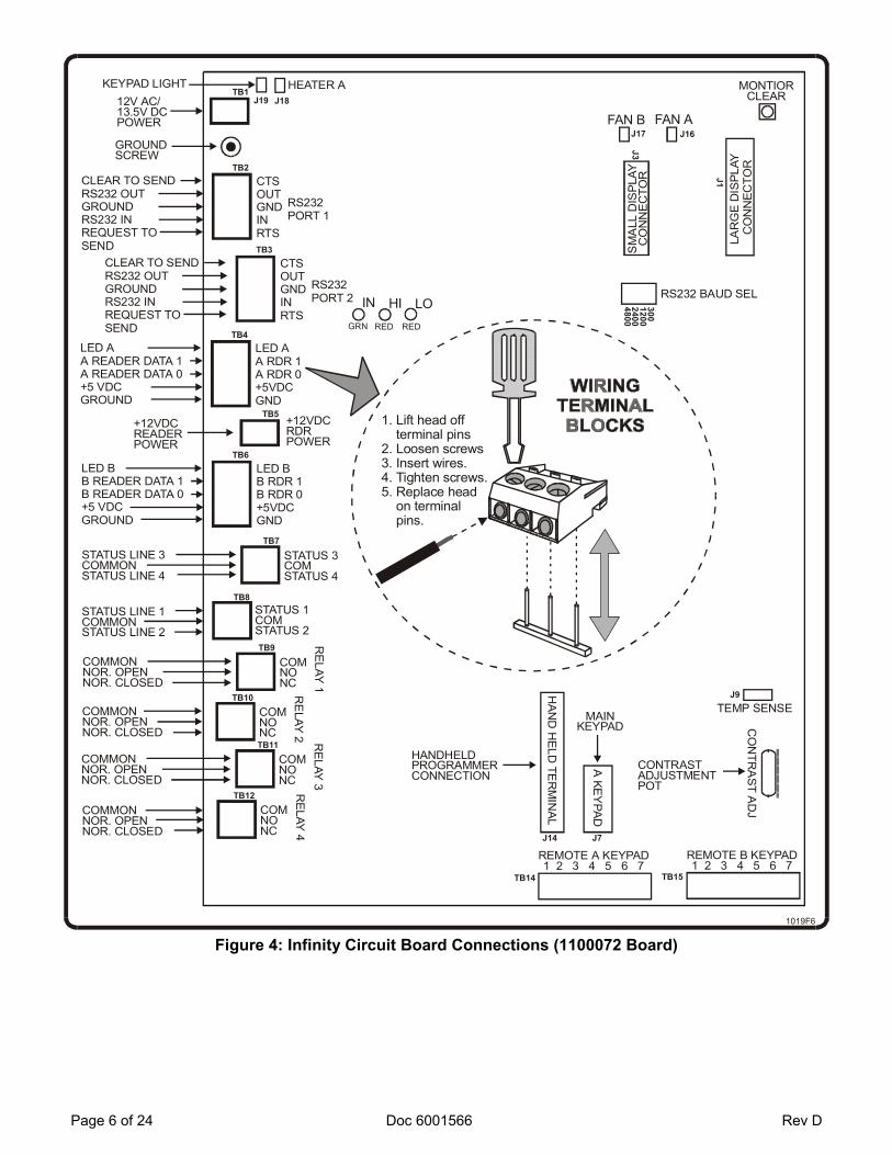
Figure 9: Telephone Interface Board, Adjustments and Indicators
MODEL 1100329 TELEPHONE INTERFACE BOARD ADJUSTMENTS
All adjustments must be made in the following order: SIDE TONE ADJUSTMENT: To adjust the side tone, the phone line must be connected to the unit. Infinity B Units: Adjusting the side tone balance is unnecessary. 1. Enter programming mode: Enter three (3) asterisks “ ” followed by the six (6) digit password.
Multi-Link Units: When adjusting the first unit (for Infinity “S” or “M” only) or a secondary unit of a multi-link chain, enter a password of “000000”.
2. In programming mode, press “69 + # (or ENTER)” on the keypad. The unit will connect to the phone line. You will hear two consecutive beeps followed by the modem carrier tone.
3. Locate the -080 daughter board. 4. Adjust LINE BAL 1 until the tone is at its lowest level. Use an adjustment tool with a 0.1” wide blade. 5. During adjustment: (a) You may hear the recording of an operator’s voice. Disregard it. Adjusting LINE
BAL 1 will not vary the operator’s voice level. (b) If the system times out (default = 30 seconds), repeat step 2 and continue to adjust the side tone until minimum sound level is achieved. The system time out will not affect prior adjustments. (c) Multi-Link Units: When adjusting the first unit (for Infinity “S” or “M” only) or a secondary unit of a multi-link chain, after completing each Line Balance adjustment, repeat steps 1 and 2 and continue to adjust the side tone balance. Exiting and re-entering programming mode will not affect prior adjustments.
6. Perform the same procedure on LINE BAL 2. 7. Confirm that LINE BAL 1 is still adjusted to the lowest tone level.

Rev D Doc 6001566 Page 21 of 24
MIC. SENSITIVITY: The microphone’s sensitivity may be adjusted on the daughter board at MIC SENS (see Figure 9). The mic. sensitivity affects the volume heard by the tenant. NOTE: Use an adjustment tool with a 0.1” wide blade. INSUFFICIENT VOLUME: The volume may be raised or lowered by adjusting the "SPEAKER LEVEL" pot. CLICK LEVEL: Adjust the click level as follows: 1. Set the "CLICK LEVEL" pot (see Figure 9) to the center of its range. 2. Enter a directory code of a tenant with a rotary-dial telephone. 3. When they answer, ask them to dial a "9". The "CLICK" LED should flash until the strike relay opens the
door and the board emits a click. 4. If the relay doesn't click and the "CLICK" LED doesn't flash regularly, turn the "CLICK LEVEL" pot
clockwise and repeat steps 2 and 3 until both responses are received. 5. If the relay clicks and the "CLICK" LED stays on or doesn't flash regularly, turn the "CLICK LEVEL" pot
counter-clockwise and repeat steps 2 and 3 until both responses are received.
C. CARD ENTRY
1. Program the unit with some test cards and facility codes as described in the accompanying manual, "INSTRUCTIONS FOR PROGRAMMING AND USE OF ALL INFINITY SYSTEMS".
2. Test the card entry feature with a valid card number and facility code. If the card is accepted, the LEDs on the front of the reader should change appearance, and the relay should activate. Card readers have different LED patterns, so the change depends on the type of reader.
3. Infinity software can be used to test card readers. Area 23, selection 3 will indicates if a specific card has been programmed in, but not if it is valid. If the relay does not activate when the card is used, check to make sure the card's facility code matches the system (see programming instructions). Area 23, selection 4 can also be used to see determine the card was read properly, but was denied access for another reason, i.e., the card is not valid (30-bit only).
D. CODE ENTRY
1. Program the unit with some test codes as described in the accompanying manual, "INSTRUCTIONS FOR PROGRAMMING AND USE OF ALL INFINITY SYSTEMS".
2. Test the code entry feature with a valid code. The relay for that keypad should activate when the code is entered.
3. Infinity software can be used to test code entry. Area 23, selection 4 (see programming instructions) can be used to determine if the code was received properly, but was denied access for some other reason (for example, the code is out of its time zone).
E. POSTAL LOCK, REQUEST FOR ACCESS, DOOR POSITION MONITORING
Test these features by shorting across the appropriate terminal block pins, then check to make sure the associated relays activate and deactivate properly. Once your wiring is in place, test the functions again.

Page 22 of 24 Doc 6001566 Rev D
F. BUILT-IN MODEM
1. Call the system using a Hayes-compatible modem hooked to a terminal (or PC using terminal emulation software).
2. If connection is made, the "TRANSMIT MODEM DATA" and "RECEIVE MODEM DATA" indicators (see Figure 9) should flash as data is transmitted and received, and you should be able to access the programming mode described in Section 10 of the programming manual.
3. If connection is not made, ensure the baud rates of both modems match. For an 1100329 board, the baud rate must be set to 300, 1200, or 2400 baud to communicate with the Infinity system's 300 (or 2400) baud modem.
G. MULTIPLE ENTRY
1. Disconnect the telephone line from the system and try dialing a number. If the system displays a "LINE IN USE - PLEASE WAIT" message, this feature is working correctly.
2. Reconnect the telephone line and the system should beep and display the message "LINE IS NOW AVAILABLE - PRESS # TO TRY TO CALL AGAIN". Make a call or press the "✳" button until the welcome message returns.
H. METHOD OF DIALING
1. The Infinity is factory set to use DTMF tone dialing. To change to rotary (also called pulse) dialing, enter the programming mode (see programming manual) and press "55" followed by "ENTER".
2. When the new programming prompt appears on the screen, the change has been made. To change the method back to DTMF tones, use the same procedure except substitute "60" for "55".
I. OPTIONAL CCTV MONITORING
Figure 10: CCTV Power Supply Board J1 Connector
1. When the monitor or television is turned on, picture will appear. • If no picture appears, check the J1 connector on the CCTV power supply board (see Figure 5). A. Make sure the connector is firmly attached to the power supply board. B. The connector is keyed and must be attached in the correct direction. From left to right, the wires
should be: yellow (video); blue (ground); and red (power).

Rev D Doc 6001566 Page 23 of 24
FCC REQUIREMENTS INSTALLATION When you are ready to install this system, call your telephone company and give them the following information:
1. The telephone number of the line to which you will connect the system. 2. The FCC registration number for the system, which is DS83E7 - 17196 - ALE. 3. The ringer equivalence number (REN), which is 0.1B.
This system connects to the telephone line by means of a standard jack called the USOC RJ11C. If this type of jack is not available where you want to install the system, you will need to order it from the telephone company. TYPE OF SERVICE Your Sentex Infinity system is designed for standard-device telephone lines. They should not be used on coin service or party lines. If you have any questions about your telephone line, such as how may pieces of equipment you can connect to it, the telephone company will provide this information upon request. TELEPHONE COMPANY PROCEDURES The goal of the telephone company is to provide you with the best service it can. In order to do this, it may occasionally be necessary for them to make changes in their equipment, operations, or procedures. If these changes might affect your service or operation of your equipment, the telephone company will give you notice, in writing, to allow you to make any changes necessary to maintain uninterrupted service. IF PROBLEMS ARISE If any of your telephone equipment is not operating properly, you should immediately remove it from your telephone line, as it may cause harm to telephone network. If the telephone company notes a problem, they may temporarily discontinue service. When practical, they will notify you in advance of this documentation. If advance notice is not feasible, you will be notified as soon as possible. When you are notified, you will be given the opportunity to correct the problem and informed of your right to file a complaint with the FCC. In the event that any repairs are ever needed on your system, they should be performed only by an authorized representative of Sentex Systems, Inc. DISCONNECTION If you should ever decide to permanently disconnect your Infinity system from its present line, please call the telephone company and let them know of this change. RADIO FREQUENCY This equipment has been tested and found to comply with the limits for a Class B digital device, pursuant to part 15 of the FCC Rules. These limits are designed to provide reasonable protection against harmful interference when the equipment is operated in a residential environment. This equipment generates, uses, and can radiate radio frequency energy and, if not installed and used in accordance with the instruction manual, may cause harmful interference to radio communications. However, there is no guarantee that interference will not occur in a particular installation. If this equipment does cause harmful interference to radio or television reception, which can be determined by turning the equipment off and on, the user is encouraged to try to correct the interference by one or more of the following measures: 1. Reorient or relocate the receiving antenna. 2. Increase the separation between the equipment and receiver. 3. Connect the equipment into an outlet on a circuit different from that to which the receiver is connected. 4. Consult the dealer or an experienced radio/TV technician for help. If necessary, the user should consult the dealer or an experienced radio/television technician for additional suggestions. The user may find the following booklet prepared by the FCC helpful: "How to Identify and Resolve Radio-Television Interface Problems". This booklet is available from the United States Government Printing Office. Washington, D.C., 20402. Stock No. 004-000-00345-4.

Page 24 of 24 Doc 6001566 Rev D
DOC REQUIREMENTS NOTICE: The Canadian Department of Communications label identifies certified equipment. This certification means that the equipment meets certain telecommunications network protective, operational, and safety requirements. The Department does not guarantee the equipment will operate to the user’s satisfaction. Before installing this equipment, user’s should ensure that it is permissible to be connected to the facilities of the local telecommunications company. The equipment must also be installed using an acceptable method of connection. In some cases, the company’s inside wiring associated with a single line individual service may be extended by means of a certified connector assembly (telephone extension cord). The customer should be aware that compliance with the above conditions may not prevent degradation of service in some situations. Repairs to certified equipment should be made by an authorized Canadian maintenance facility designated by the supplier. Any repairs or alterations made by the user to this equipment, or equipment malfunctions, may give the telecommunications company cause to request the user to disconnect the equipment. Users should ensure for their own protection that the electrical ground connections of the power utility, telephone lines, and internal metallic pipe system, if present, are connected together. This precaution may be particularly important in rural areas. Caution: Users should not attempt to make such connections themselves, but should contact the appropriate electrical inspection authority, or electrician, as appropriate. The Load Number (LN) assigned to each terminal device denotes the percentage of the total load to be connected to a telephone loop, which is used by the device to prevent overloading. The termination on a loop may consist of any combination of devices subject only to the requirement that the total of the Load Number of all the devices does not exceed 100. The load number for the Infinity system is 38.