Invalidation Notifications—Notifications—Addendum Notification ...

REGULATOR INFORMATION DISTRIBUTION TEM (RIDS)
ACCESSION NBR:7903070260 DOC ~ DATE: 79/02/28 NOTARIZED: NO DOCKETFACIL ~ 50 410 NINE MILE POINT NUCLEAR STATIONS UNIT 2g NIAGARA MOHA 05000010
AUTHBYNAME
AUTHOR AFFILIATIONBARTLETTPJ. NIAGARA MOHAWK POWER
CORP'ECIP
~ NAME RECIPIENT- AFFILIATIONCARLSONER AT ~ REGION 1 g PHILADEl PHIAE REACTOR CONSTRUCTION & ENGINEERI
SUBJECT: FOLLOWUP ON NOTIFICATIONS OF 780621 8 781122 RE POTENTIALLYREPORTABLE DEFICIENCIES IN CADWELD SLEEVES ON CONTAINMENTLINER KNUCKLE PLATE ~ FORWARDS DESCRIPTIONEANALYSIS 8CORRECTIVE AOITON ~
OISTRISUTION COOE: SOI90 COPIES RECEIYEO:LTR g ENCL SIZE:~TITLE ~ CONSTRUCTION DEFICIENCY REPORT (10CFR50 ~ 55E) ~
NOTES:
RECIPIENTID CODE/NAME
ACTION: i~ PM H- 5'Iver20 lA L.~c.g~t
COPIESLTTR ENCL
1 1
1 1
R~CIPI~~TID CODE/NAME
15 BC Z~r&21 AD VIS~
+i&'OPIESLTTR ENCL1 1
1 1
INTERNAL:05 ISE08 MPA10 QAB12 JORDAN'/IE16 AD FOR ENGR17 AD REAC SFTY22 DIR DPM
1 1
2 21 1
1 1
1 1
1 1
1 1
1 1
02 NRC PDR07 EDO 5 STAFF09 DEPY DIR DPM11 STANDRDS DEV13F IELD COOR/IE17 AD PLANT SYS19 AD SYS/PROJ23 OELD
1 1
1 1
1 1
1 1
1 1
1 1
1 1
1 1
EXTERNAL: 03 lPDR24 ACRS
1 1
16 1604 NSIC 1 1
TOTAl NUMBER OF COPIES REQUIRED: LTTR 39 ENCL 39

m
~ I
N V
fi
N II
hl

M 7 MIAS/OAFQ U MQHAWt
NIAGARA MOHAWKPOWER CORPORATION/300 ERIE BOULEVARDWEST, SYRACUSE, N.Y. 13202/TELEPHONE (3>5) 474-1511
February 28, 1979
Office of Inspection and EnforcementRegion IAttn: Mr. R. T. Garison, ChiefReactor Construction and Engineering
Support BranchU. S. Nuclear Regulatory Commission631 Park AvenueKing of Prussia, PA 19406
Dear Mr. Garison:
Re: Nine Mile Point Unit,2Docket No. 50-410
On June 21, 1978, Mr. R. W. McDaughy of your staff wasnotified of a potentially reportable deficiency under 10CFR50.55(e)at the Nine Mile Point Unit 2 construction site. The conditionconcerned magnetic particle weld indications in the semi-.automatically welded cadweld sleeves on the containment linerknuckle plate. Subsequent investigation of these indicationsrevealed a second potentially reportable deficiency
concerning'ack
of fusion along the J-bevel area of the cadweld sleeves.This second potentially significant deficiency was reported toMr. L. Narrow of your- staff on November 22, 1978.
Based on the further investigation and evaluation of thismatter, we have determined that the June 21, 1978 occurrencedid not have any adverse safety implications. The conditionreported on November 22, 1978 could have been a safetyhazard if left uncorrected.
Attached is a report providing a description of each ofthese conditions, an analysis of the. safety implications foreach, and the corrective action to be taken. This report issubmitted in accordance with Title 10, Section 50.55(e) ofthe Code of Federal Regulations.
Attac ment
Very truly yours,NIAGARA MOHAWK POWER CORPORATION
James BartlettExecutive Vice President
QO
yc: Inspection 6 Enforcement BranchWashington, D. C.
79OSOVO Sm


~ I. INTRODUCTION
On June 21, 1978, the Nuclear Regulatory Commission was notifiedby the Niagara Mohawk Power Corporation that a potential reportable
'eficiencyexisted at the Nine Mile Point Nuclear Station Unit 2construction site. This condition concerned magnetic particleindications, predominately in the toe area of the cadweld sleeveto the containment liner knuckle plate welds. Figure 1 shows thelocation of these sleeves with respect to the containment liner.Figure 2 shows the details of a typical weld joint.The Nuclear Regulatory Commission was notified that there was awork stoppage at the Nine Mile Point Unit 2 construction sitefrom June 20, 1978 until September 1, 1978. Therefore, theinvestigation of. this condition was limited during this time.
During the subsequent ultrasonic testing investigation into thesemagnetic particle indications, a second potential reportabledeficiency was discovered. This deficiency was characterized byentrapped slag and lack of fusion along the J-bevel area of someof the cadweld sleeves (see Figure 2). This condition wasreported to the Nuclear Regulatory Commission in accordance with10CFR50.55(e) on November 22, 1978. Extensive analyses and testswere performed to determine the extent of this welding deficiency.
II. DESCRIPTION OF DEFICIENCY
Magnetic particle weld indications in the cadweld sleeve tocontainment liner knuckle plate area. welds were initiallydiscovered while performing an magnetic particle inspection onbase metal aieas resulting from the removal of shop-installedtemporary stiffeners. These indications were located predominatelyin the toe area of the welds (see Figure 2). These welds hadbeen magnetic particle inspected by the containment linerfabricator, and the records showed that no significant indicationswere found. Further investigation resulted in 255 magneticparticle indications out of a total of 1824 cadwelds. Thiscondition was then reported to the Nuclear Regulatory Commissionon June 21, 1978 in accordance with 10CFR50.55(e).
A three-pronged investigation was initiated to examine themagnetic particle indications., Investigations were conductedon equivalent test sleeves, on a mockup portion of the contain-ment liner, and on production items in the field.Twenty-two equivalent test sleeve assemblies (44 cadwelds) of thesame design were evaluated. The methods used were nondestructiveexamination (ultrasonic testing and magnetic particle testing),tensile testing, bend testing, sectioning for visual examination,and microstructure examination. The results of the equivalenttest sleeve investigation were as follows:


1. Meld plate toe d'efects were not found in the equivalenttest sleeve assemblies of the same design.
2. The microstructure was considered typical for a multiplepass weld joint and the materials involved.
3. The tensile and bend test assemblies broke in the area ofthe sleeves, i.e., the weld did not fail.Visual examination of 90-degree sections did not revealtoe defects as were found in the field. However, itwas observed that J-bevel defects were found in 90-degreesections of two equivalent test sleeve assemblies. Atthis time, the extent of these J-bevel defects was notknown.
A mockup of the cadweld sleeve assembly was made to determine ifthe toe area magnetic particle defects could have been caused bywelding procedure variables, plate surface cleanliness, or platedeflection. This investigation was stopped when it was dis-covered that the toe area magnetic particle defects were relatedto entrapped slag and possible lack of fusion.
The ultrasonic test investigation of the toe area magnetic particledefects revealed the second potential reportable deficiency.This was a lack of fusion along the J-bevel area of the cadweldsleeve (see Figure 2). Eighteen of the 255 welds with magneticparticle indications and 24 of the remaining welds withoutmagnetic particle indications were selected randomly for in-vestigation. Eleven of the 18 and six of the 24 revealed linearindications 1/4 inch and greater in the J-bevel area forcircumferential lengths up to 360 degrees.
Four cadweld sleeve assemblies representing the worst-caseultrasonic test results were removed from the liner andtensile tested after having rebar stubs cadwelded at each end(see Figure 1). ln all cases, the rebar failed and not the weld.Subsequent cross-sectioning confirmed the ultrasonic test resultsas accurate. Photographs of,the cross-sections are provided asFigures 3 and 4. Two additional onsite sleeve.welds were groundin the J-bevel area and also confirmed the accuracy of theultrasonic. testing results.
An additional 257 cadweld sleeve welds were ultrasonicallyinvestigated to obtain a larger sample size. Twenty-nine ofthese were identified to have J-bevel defects as extensive orgreater than the four that were previously tensile tested. Tenof these twenty-nine were also tensile tested. All ten weldswithstood more than 125 percent of the minimum rebar yieldstrength of 250 kips. Further testing was halted and thecorrective action program described below was developed.


III. ANALYSIS OF SAFETY IMPLICATIONS
The welds are designed in the elastic range so that the reinforcingsteel tensile load will not adversely affect the containment linerintegrity. In order to ensure this, the welds have been designedto carry a design load of 180. kips, and an ultimate load of 280kips.The magnetic particle indications of the fillet weld toe area areconsidered to be a departure from the specification requirements;however, they are not considered to be a safety hazard. Alldesign loads were investigated by analysis. It was determinedthat crack propagation either along the fillet fusion zone tothe containment liner plate, into the plate, or into the filletweld would not occur.
The second reported deficiency, the slag and lack of fusion alongthe cadweld sleeve J-bevel area in the containment liner knuckleplate is a departure from the specified technical requirements.This would be considered a potential safety hazard if it were toremain uncorrected. The design requirements for allowable stressin these welds and the. containment liner plate could be exceeded
'with the type of J-bevel d'efects disclosed.
Due to the problem identified in the containment liner knuckleplate, further investigations were conducted relative to thecadweld sleeve to base plate welds at the junction of the reactorpedestal and the mat. Figure 5 shows the location of thesewelds. All 680 cadweld sleeve welds in this location had previouslypassed magnetic particle inspection. Of these, 625 cadweldsleeve welds were performed using a manual stick welding method,and tensile tests were conducted on equivalent test assemblies.All the test assemblies failed in the number 18 rebar at loadshigher than 125 percent of the minimum rebar yield strength, andno failure occurred in the welds. The remaining 55 welds inthis location were performed by the same welding method andprocedure as the liner knuckle welds. 'The exact location ofthese 55 welds is not known except that 10 are in one 90-degreesector and 4P are in another:90-degree section of thepedestal-to-mat junction (see Figure 6).
An investigation into the structural integrity of the reactorpedestal was performed. Prior to June 1975 there was noprovision in the design for a rigid structural connection ofthe drywell floor and the'containment wall. In this configura-tion, inflatable seals, were required between the floor andthe primary containment wall to separate the drywell and wetwellatmospheres. Since that time, it was decided to change thatconfiguration, and the drywell floor was rigidly connected to theprimary containment wall. This design change was reported to theNuclear Regulatory Commission in a letter dated July 29, 1976,from Mr. G. K. Rhode of Niagara Mohawk Power Corporation toMr. D. B. Vassallo of the Nuclear Regulatory Commission. Because

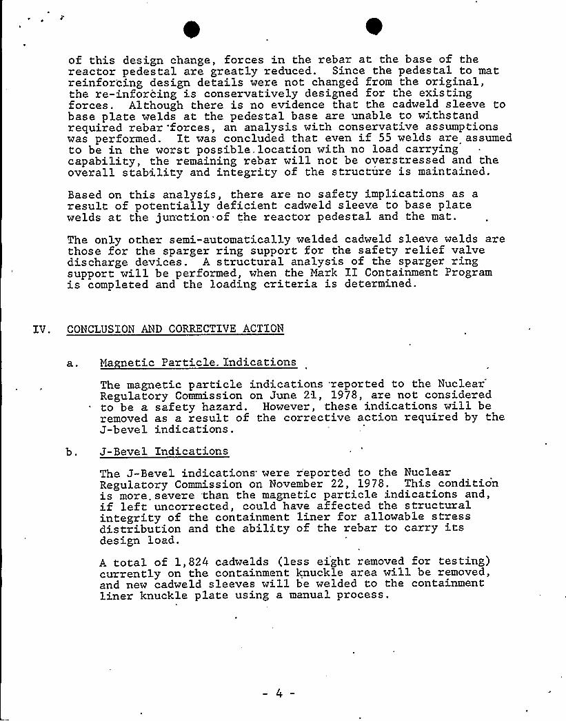
0of this design change, forces in the rebar at the base of thereactor pedestal are greatly reduced. Since the pedestal to matreinfor'cing design details were not changed from the original,the re-inforcing is conservatively designed for the existingforces. Although there is no evidence that the cadweld sleeve tobase plate welds at the pedestal base are unable to withstandrequired rebar forces, an analysis with conservative assumptionswas performed. It was concluded that even if 55 welds are assumedto be in the worst possible. location with no load carryingcapability, the remaining rebar will not be overstressed and theoverall stability and integrity of the structure is maintained.
Based on this analysis, there are no safety implications as aresult of potentially deficient cadweld sleeve to base platewelds at the jun'ction of the reactor pedestal and the mat.
The only other semi-automatically welded cadweld sleeve welds arethose for the sparger ring support for the safety relief valvedischarge devices. A structural analysis of the sparger ringsupport will be performed, when the Mark II Containment Programis completed and the loading criteria is determined.
IV. CONCLUSION AND CORRECTIVE ACTION
a ~ Ma netic Particle. Indications
The magnetic particle indications reported to theNuclear'egulatoryCommission on June 21, 1978, are not considered
to be a safety hazard. However, these indications will beremoved as a result of the corrective action required by theJ-bevel indications.
b. J-Bevel Indications
The J-Bevel indications'ere r'eported to the NuclearRegulatory Commission on November 22, 1978. This conditionis more. severe than the magnetic particle indications and,if left uncorrected, could have affected the structuralintegrity of the containment liner for allowable stressdistribution and the ability of the rebar to carry itsdesign load.
A total of 1,824 cadwelds (less eight removed for testing)currently on the containment knuckle area will be removed,and new cadweld sleeves will be welded to the containmentliner knuckle plate using a manual process.

\

J-Bevel Indications
The 55 suspect welds in the junction of the base plateand reactor pedestal have no safety implications andrequire no corrective action as discussed in Section TIlabove.
The welds in the sparger ring support will be studied andcorrective action taken in the future, if required. TheNuclear Regulatory Commission will be informed of ourevaluation of this matter.


~ Q ~
~ ~ ~ ~ ~~ S 0
Ak

r

418 RBB-1892 3A CADWELO~,
tl2 ra I.D.
33r O.D.
SLEEVE ~ J - 8 E V ."- ' R E A~
p'0
V/EL D
r6'
45
FILLE ThVELD
TOE AREA
II
1'e
e—C ONTAI NMENTPLAT E
FILLET
CADVlE LD JOIN T DETAI L


~ ~tlr r t «0 rt t«'/ rt ~ « t ~ ~tttt isn't "~ t« ~, t -t trC~.-? rttrt» St,QC t,t ~
«t I~t
t\
C ROSS
1
SE'CTtON OF Lit|En CADI'ELD SLEEVE V/ELDER .
gt ~
-SLEEVE
WELD
i7r '
t
.>,p
Jt BEv E L LAcKOF FUSION
t?
, PLAT Et ) Yu~~g gyp, ~pl
«+j-'a ~i%.';~.
Ct t t 'ttH
t- ~
't )
petit
"'*I
"J BEVEL.; LACK OF
FUSION
I r
tt ~ „-'
'
tr
t ~ '
4'
~,
?
t
~ iCt r
~$". t'$h
ft ~
$M
?
F jter-t'
g+'-"~t
)t t
P.fSj,~-~~~~


CROSS sEOIois oF LlwE
a
R CADW:-LO SLEE'jt'E
tv
.",'i'igloo"',".„"'
S E LDS ..';.',-'=',"„:"$ f . +A (".~",
t>=4tV'r,a
gC
rh*1
SLE t".
4 rr!
!yt
l
t
II *
!
'T,,f
I ~ '!
WE LD
PLAT E~ t
a
t
f. "-f4~~u" f ~
<''t<a4tr.'S .
EI.LACK'4l
~ $ .
h! I,
~ 'C 'f
g@~4' "s" ~."-'=4<~i"'8" q 0"4~4"
1'f. r
hl
~ '
hI
*
t'
t';,
~. J BEVELLACK OF„...
. ".FUSION '':,.'!
J.
!
't
'g~V'hf %5
4 tft'g,!elm(Sr If Qga'r,t ~%.
4th lk
ther ~ t ~ "'287'l9-'l 'f ~k':fI-.~-
SAfi,h gV ) 1 N
'h ~ t!
F r ~ ~
kr4 ~
Fl G.4~ ~


0
o'l~ ~P
~ ~
W
0
~ ~L
4 j
) y 0~
0
0 ~ g 0
~ g g~ 0 I
~g
e 0 ~ o~ ~
~ ~ ~
~ ~ ~
0
~ ~ 1
I ~ all
) i p
~ 0 g ~ 0
l k ~ k
S ~ Q
s ~ a ~ e a ~ s g ~


a,
SKETCH SHOWIING 4 SEGMENTS GF
PEDESTAL ASSEMBLY
SEGMENT 3 SEGMENT 1
SEGMENT 4 SEGMENT 2
P
SEGMENT 1 - SUSPECT 45 - B-SERIES CADWELD SLEEVES
WERE WELDED USING SEMI™AUTOMATIC
WELDING PROCEDURE
SEGMENT 2 - NONE
SEGMENT 3 - SUSPECT 10 - B-SERIES CADV/ELD SLEEVES
'WERE WELDED USING SEMI-AUTOMATICWELDING PROCEDURE
SEGMENT 4 - NONE
FIGURE-6 '
c