Folding and Unfolding Origami Tessellation by...
10
Department of Computer Science George Mason University Technical Reports 4400 University Drive MS#4A5 Fairfax, VA 22030-4444 USA http://cs.gmu.edu/ 703-993-1530 Folding and Unfolding Origami Tessellation by Reusing Folding Path Zhonghua Xi [email protected] Jyh-Ming Lien [email protected] Technical Report GMU-CS-TR-2015-2 Abstract Recent advances in robotics engineering have enabled the realization of self-folding machines. Rigid origami is usually used as the underlying model for the self- folding machines whose surface remains rigid during folding except at joints. A key issue in designing rigid origami is foldability that concerns about finding fold- ing steps from a flat sheet of crease pattern to a desired folded state. Although recent computational methods allow rapid simulation of folding process of certain rigid origamis, these methods can fail even when the input crease pattern is extremely simple. In this paper, we take on the challenge of planning folding and unfolding motion of origami tessellations, which are composed of repetitive crease patterns. The number of crease lines of a tessellation is usually large, thus searching in such high dimensional configuration space with the require- ment of maintaining origami rigidity is nontrivial. We propose a motion planner that takes symmetry into con- sideration and reuses folding path found on the essential crease pattern. Both of these strategies enable us to fold large origami tessellation much more efficiently than the existing methods. Our experimental results show that the proposed method successfully folds several types of rigid origami tessellations that the existing methods fail to fold. 1 Introduction Rigid origami has been a fundamental model in many self-folding machines [1] that are usually composed of mechanical linkage of flat rigid sheets joined by hinges, such as the micro-thick folding actuators [2]. In the past, people have enjoyed many practical uses of rigid origami, ranging from folding maps and airbags to pack- ing large solar panel arrays for space satellites and fold- ing space telescope. In the near future, rigid origami Figure 1: Folding process of a 11×11 Miura crease pat- tern (DOF = 220) produced by the motion planner pro- posed in this paper. will take the form of self-folding machines and provide much broader applications, such as in minimally inva- sive surgery, where there is a need for very small devices that can be deployed inside the body to manipulate tis- sue [3]. Examples that illustrate the ability of transform- ing rigid origami from a shape to another can be found in Fig. 1 and Fig. 7, where a large flat sheet can be folded into a compact stick or to a tube. A key issue in designing rigid origami is foldability that determines if one can fold a given origami form one state to another. Researchers in computational origami have attempted to simulate or plan the folding motion [4, 5, 6, 7, 8]. These existing methods, however, are known to be restricted. For example, the work by Miyazaki et al. [6] only allows bending, folding-up, and tucking- in motions. Balkcom’s method [9] cannot guarantee the correct mountain-valley assignment for each crease. The well-known Rigid Origami Simulator by Tachi [8] may sometimes produce motion with self-intersection and can be trapped in a local minimum. One of the main difficulties of planning origami folding motion comes from its highly constrained folding motion in high dimensional configuration space. For example, there are 100 closed-chain constraints in the 11×11 Miura origami shown in Fig. 1. These constraints make most (if not all) existing motion planners impractical, especially for folding large origami tessellations. Moreover, it is known to the community that given a 1
Transcript of Folding and Unfolding Origami Tessellation by...
Department of Computer ScienceGeorge Mason University Technical Reports
4400 University Drive MS#4A5Fairfax, VA 22030-4444 USAhttp://cs.gmu.edu/ 703-993-1530
Folding and Unfolding Origami Tessellation by ReusingFolding Path
Zhonghua [email protected]
Jyh-Ming [email protected]
Technical Report GMU-CS-TR-2015-2
Abstract
Recent advances in robotics engineering have enabledthe realization of self-folding machines. Rigid origamiis usually used as the underlying model for the self-folding machines whose surface remains rigid duringfolding except at joints. A key issue in designing rigidorigami is foldability that concerns about finding fold-ing steps from a flat sheet of crease pattern to a desiredfolded state. Although recent computational methodsallow rapid simulation of folding process of certain rigidorigamis, these methods can fail even when the inputcrease pattern is extremely simple. In this paper, wetake on the challenge of planning folding and unfoldingmotion of origami tessellations, which are composed ofrepetitive crease patterns. The number of crease linesof a tessellation is usually large, thus searching in suchhigh dimensional configuration space with the require-ment of maintaining origami rigidity is nontrivial. Wepropose a motion planner that takes symmetry into con-sideration and reuses folding path found on the essentialcrease pattern. Both of these strategies enable us to foldlarge origami tessellation much more efficiently than theexisting methods. Our experimental results show thatthe proposed method successfully folds several types ofrigid origami tessellations that the existing methods failto fold.
1 Introduction
Rigid origami has been a fundamental model in manyself-folding machines [1] that are usually composed ofmechanical linkage of flat rigid sheets joined by hinges,such as the micro-thick folding actuators [2]. In thepast, people have enjoyed many practical uses of rigidorigami, ranging from folding maps and airbags to pack-ing large solar panel arrays for space satellites and fold-ing space telescope. In the near future, rigid origami
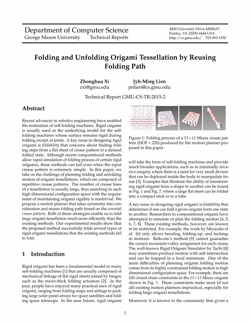
Figure 1: Folding process of a 11×11 Miura crease pat-tern (DOF = 220) produced by the motion planner pro-posed in this paper.
will take the form of self-folding machines and providemuch broader applications, such as in minimally inva-sive surgery, where there is a need for very small devicesthat can be deployed inside the body to manipulate tis-sue [3]. Examples that illustrate the ability of transform-ing rigid origami from a shape to another can be foundin Fig. 1 and Fig. 7, where a large flat sheet can be foldedinto a compact stick or to a tube.
A key issue in designing rigid origami is foldability thatdetermines if one can fold a given origami form one stateto another. Researchers in computational origami haveattempted to simulate or plan the folding motion [4, 5,6, 7, 8]. These existing methods, however, are knownto be restricted. For example, the work by Miyazaki etal. [6] only allows bending, folding-up, and tucking-in motions. Balkcom’s method [9] cannot guaranteethe correct mountain-valley assignment for each crease.The well-known Rigid Origami Simulator by Tachi [8]may sometimes produce motion with self-intersectionand can be trapped in a local minimum. One of themain difficulties of planning origami folding motioncomes from its highly constrained folding motion in highdimensional configuration space. For example, there are100 closed-chain constraints in the 11×11 Miura origamishown in Fig. 1. These constraints make most (if notall) existing motion planners impractical, especially forfolding large origami tessellations.
Moreover, it is known to the community that given a
1
crease pattern and a rigid goal configuration, the exis-tence of continuous rigid folding motion is not guaranteedin general [10]. Unfortunately, there is no known criteriafor determining whether a crease pattern or its tessel-lation can be folded between two rigid configurationswithout violating the rigidity constraint. In practice,when a crease pattern is designed, it usually requires itsdesigner to create a physical copy to verify that a rigidfolding motion does exist to bring the crease pattern to arigid goal configuration. This process can often be costlyand time consuming.
This paper models rigid origami as a kinematic systemwith closure constraints. Our ideas for addressing both ofthese rigid foldability issues include: adaptive randomizedsearch and folding path reuse. Specifically, we propose adeformation bounded folding planner (in Section 4) thatcan ensure the rigidity of the origami during continuousfolding motions; such planning has not been achievedbefore in the community. Given a tessellation formedwith repetitive crease patterns, we further take advan-tage of its symmetry to reduce the degrees of freedom(DOF). Our experimental results show strong evidencesthat this strategy can significantly speed up the com-putation (in Section 5). We further propose the ideaof essential crease pattern in Section 5.2. Fig. 1 shows afolding sequence of a 11×11 Miura origami (220 DOF,with <1% deformation) found by the proposed methodwithin 1.7 seconds1. Examples and results of foldinglarger tessellations can be found in Section 5.
Our planner requires the crease pattern for computingthe folding map. In Section 6 we propose a novel al-gorithm to obtain the crease pattern of a rigid foldedorigami from an unknown crease pattern. This allowsthe input of our system from crease patterns extendedto rigid origamis in arbitrary configurations.
2 Related Work
Planning under closure constraints. There have beenmany methods proposed to plan motion for articulatedrobots under closed-chain constraints [11, 12, 13, 14].Interestingly, we see many similar ideas used in bothclosed-chain systems and origami folding. For example,gradient decent was used by [8] for rigid origami sim-ulation and by [11] for generating valid configurationof a closed-chain system. Another example is inversekinematics, which plays the central role both in Balk-com’s simulator [9] and in constructing the so-calledkinematic roadmap [13, 15] for capturing the topology offree configuration space. Tang et al. [16] proposed an ef-ficient sampling-based planner for spatially constrainedsystems. By sampling in the reachable distance space
1All timing data reported in this paper are collected on a 2012Macbook Pro laptop with a 2.9GHz Intel Core i7 CPU and 16GB RAM.
in which all configurations lie in the set of constraint-satisfying subspaces and using a local planner, they cansignificantly reduce the computation time for finding apath.
Planning and simulating origami motion. Miyazaki etal. [6] simulated origami folding by a sequence of simplefolding steps, including bending, tucking in, and foldingup in 1996. It is easy to reconstruct an animation from asheet of paper to the final model. However, the simplic-ity of folding steps limits the types of origami modelsthat could be represented in the system. Consequently,this method is not suitable for many complex origamimodels whose folding process cannot be represented assimple folding steps such as the Miura pattern shown inFig. 5(a). Song et al. [17] presented a PRM based frame-work for studying folding motion. However, their kine-matic representation of origami is a tree-structure modelwhose folding angle of each crease line is independentof other crease lines. Although a tree-structure modelgreatly simplifies the folding map that can be easily de-fined along the path from base to each face, this modelis not applicable to represent the majority of origamis,such as the one shown in Fig. 5(a), due to their closureconstraints. Balkcom [9] proposed a simulation methodbased on the ideas of virtual cutting and combinationof forward and inverse kinematics using a rigid origamimodel. Although this approach is computational effi-cient, the correctness of mountain-valley assignment foreach crease is not guaranteed, i.e., a mountain fold canbecome a valley fold or vice versa. Tachi [8] proposed aninteractive simulator for rigid origami model (known asRigid Origami Simulator (ROS)) which generates foldingmotion of origami by calculating the trajectory by pro-jection to the constrained space based on rigid origamimodel, global self-intersection avoidance and stackingorder problems are not considered in his work. An etal. [2] proposed a new type of self-reconfiguration sys-tem called self-folding sheet. They first construct the cor-responding folded state for a given crease pattern andangle assignment then continuously unfold the paperusing local repulsive energies (via a modification of ROS[8]). By reversing the unfolding sequence, they obtainedthe path starting from a flat sheet and ending with the de-sired folded state. Akitaya et al. [18] proposed a methodfor generating folding sequences of origami, however,their system can only handle flat-foldable origami. Morerecently, Xi and Lien [19] proposed a randomized searchalgorithm via nonlinear optimization to find the inter-mediate folding steps which guarantees self-intersectionfree, however, the motion it found can lead to arbitrarydeformation.
2
3 Preliminaries: Rigid OrigamiModel
3.1 Crease Pattern
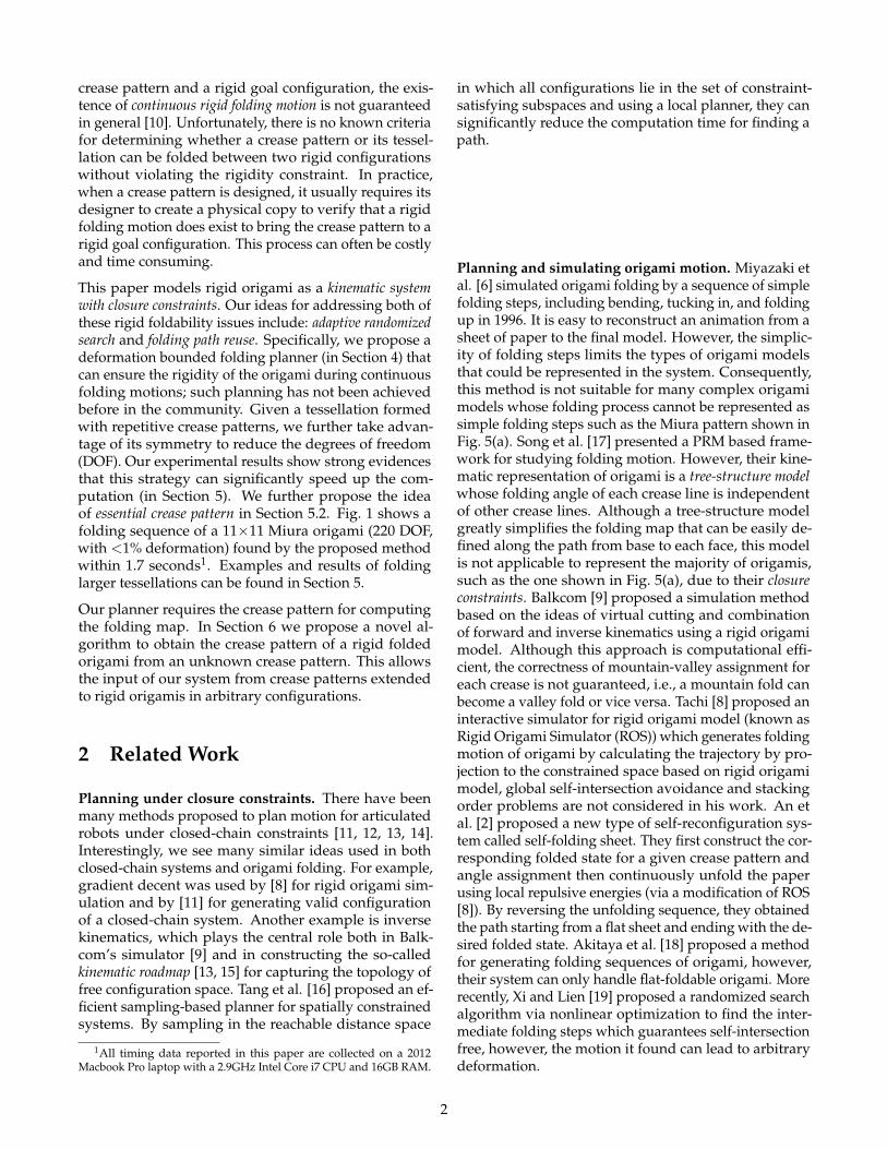
In this paper, we use crease pattern, a straight-edgedgraph embedded in the plane, to represent the rigidorigami model. Fig. 2 shows the crease patterns of theorigami tessellations used in our experiments (in Sec-tion 5). An edge of this graph correspond to the locationof a crease line in an unfolded sheet. A crease line canbe either mountain folded or valley folded. A mountainfold forms a convex crease at top with both sides foldeddown. On the other hand, a valley fold forms a concavecrease.
Real & Virtual Vertices Vertices in crease pattern can becategorized into two groups: real vertices and virtualvertices. Vertices on the boundary of a pattern are con-sidered as virtual vertices and they cannot act as witnessvertices for the purpose of computing folding map. Us-ing the folding map of a given configuration, we caninstantaneously fold a crease pattern to a folded shape.All other vertices are considered as real vertices. For ex-ample, vertices v1, v2, v3 and v4 are the only real verticesin Fig 5(a) and all the other vertices are virtual vertices.
(a) 4×4 Miura (b) 4×4 Quad
(c) 4×6 Waterbomb (d) 12×14 Waterbomb
Figure 2: Crease patterns used in the experiments. Themountain creases are shown as solid lines in red, valleycreases are show as dashed lines in blue.
Crease Lines We use l(i,j) to denote the crease line thatconnects vertex vi and vj in which at least one vertexshould be real. Boundary edges in the crease patternare not considered as crease lines. Each crease line l(i,j)is associated with a plane angle α(i,j) which is the anglebetween −→vivj and [1, 0]T (x-axis) and a folding angle ρ(i,j)which equals to π minus the dihedral angle betweentwo faces sharing the crease line l(i,j). The value of ρ isbounded in [-π, π] to avoid adjacent faces penetratingeach other.
Faces We use F(i,j,...) to refer to a face in the crease pattern,where {vi, vj, ...} are its vertices. The crease line l(i,j)belongs to two faces F(i,j,...) and F(j,i,...).
For a non-triangular crease pattern, we will triangulateit first, newly added diagonals are called virtual edgeswhose folding angles should always be zero otherwisethe panel will be bended.
3.2 Configuration
We use the folding angles of all crease lines to representthe configuration of an origami model. For an origamiwith n crease lines, its configuration is represented asC = [ρ(i1,j1), ρ(i2,j2), · · · , ρ(in ,jn)]
T . Given a configurationC, we can classify C according to its foldability and feasi-bility.
Foldability For a real vertex vi in a multi-vertex creasepattern, let Ai be the 4 × 4 matrix which translates apoint in <3 by vi. Let B(i,j) be the 4× 4 matrix in ho-mogeneous coordinates which rotates around z-axis forplane angle α(i,j), and let C(i,j) be the 4 × 4 matrix inhomogeneous coordinates which rotates around x-axisfor folding angle ρ(i,j). Then the 4× 4 folding matrixof counter-clock-wisely crossing crease line l(i,j) withwitness vertex vi is χ((i,j),i) = AiB(i,j)C(i,j)B
−1(i,j)A−1
i .
Let {l(i,j1), l(i,j2), ... , l(i,jci )} be the crease lines incident
to vi, ordered by their plane angles α(i,j), where ci is thenumber of crease lines incident to vi. If we pick F(i,jci ,...)
as F0 and fix it in the xy-plane, we define the local fold-
ability matrix for real vertex vi as L(vi) =ci∏
t=1χ((i,jt),i).
Finally, the necessary condition of foldability is:
L(vi) = I, ∀vi (1)
This condition for multi-vertex rigid origami was firstdiscovered by Balcastro and Hull in 2002 [7].
Feasibility There are several properties that an origamirigid folding should have: (1) unstretchable, (2) flat (pla-nar) for all faces, and (3) free of self intersection. A fold-able configuration only guarantees the first two proper-ties. In order to check if C is free of self intersection, weneed a folding map for each face. A folding map is a func-tion that maps a point in <2 to the corresponding pointof folded state in <3 for a given foldable configuration.
4 Folding via Adaptive Random-ized Search
Searching for a valid folding motion of an origami tessel-lation is difficult because of its highly constrained nature
3
and high dimensional configuration space. In particular,there are n closed-chain constraints for an origami withn real vertices. These constraints make most (if not all)existing probabilistic motion planners impractical. In[20] we show that for rigid origami with closure con-straint, the portion of free space is near to zero evencertain amount of deformation is allowed.
In this paper, we extend FROCC [19] which uses an adap-tive randomized search with nonlinear optimization.FROCC samples a random configuration Crand aroundcurrent configuration Cτ and pushes Crand to a foldableconfiguration C∆ via nonlinear optimization (NLOpt). IfC∆ is feasible and closer to the goal, it then replaces Cτ
with C∆ and keep doing so until goal is reached. FROCCworks well in practice, however, it also has several issuesthat we are trying to address in this paper.
Objective Function Intuitively, because each real vertexof a foldable configuration must satisfy the constraintin Eq. (1), for a given real vertex vi, we want the lo-cal foldability matrix L(vi) to be as close to an identitymatrix I as possible. However, the objective functionF(C) = ∑i |L(vi)− I| used by FROCC could be easilytrapped at local minima. In this paper, we updated theobjective function to Eq. (2).
F(C) = maxi|L(vi)− I| (2)
If L(vi) 6= I, deformation will be introduced, in Eq. (2)we try to minimize the maximum deformation whichworks better than the original one.
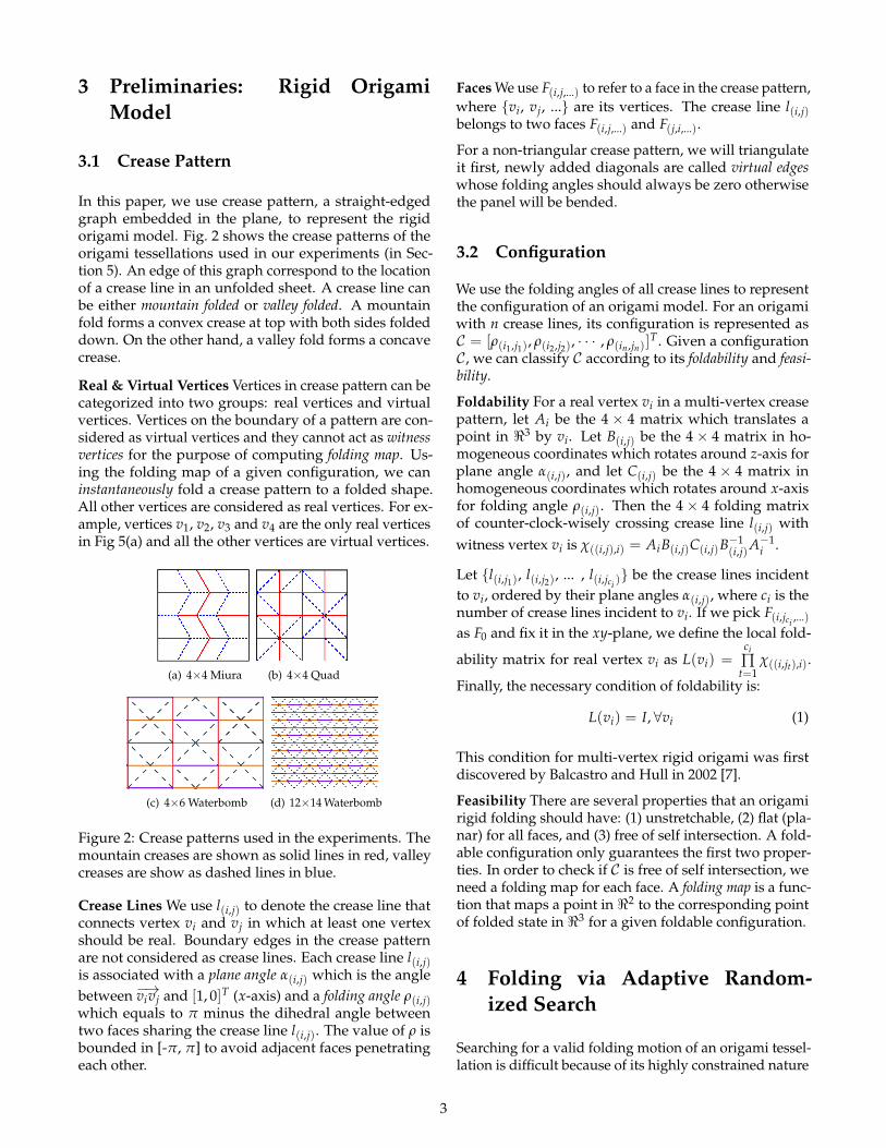
Deformation Bounded Search (DBS) During random-ized search, NLopt finds an optimal configuration Caround Cτ , but the value of F(C) in Eq. (2) may be nonezero. This is because local-foldable configuration mightnot exist around Cτ or NLopt is not able to find it withingiven iterations. Consequently, none-zero F(C) leadsto deformation in folded oragami. However, directlybounding F(C) [19] does not give us a quantitative rigid-ity measure. To illustrate this, in Fig. 3, we show defor-mation measured in terms of the stretch and shrinkageof edges given that F(C) < 0.1. We can see that withthe increase of size of the crease pattern, though theirfolding paths still look identical (with the naked eye),the edge deformation is quite dramatic (increased from≈1.5% in 3×3 Miura to ≈10% in 5×5 Miura).
Thus, we propose a deformation bounded search (DBS)that checks the maximum amount of deformation mea-sured by the change of edge length including virtualedges which is defined as (||e f olded|| − ||eorg||)/||eorg||.In DBS, we use the same objective function in Eq. (2) butonly accept configurations that are within the deforma-tion bound given by the user. The folding path foundby DBS is guaranteed to be deformation bounded andself-intersection free, which has not been achieved be-fore in the community. Folding paths for the 3x3 Miura
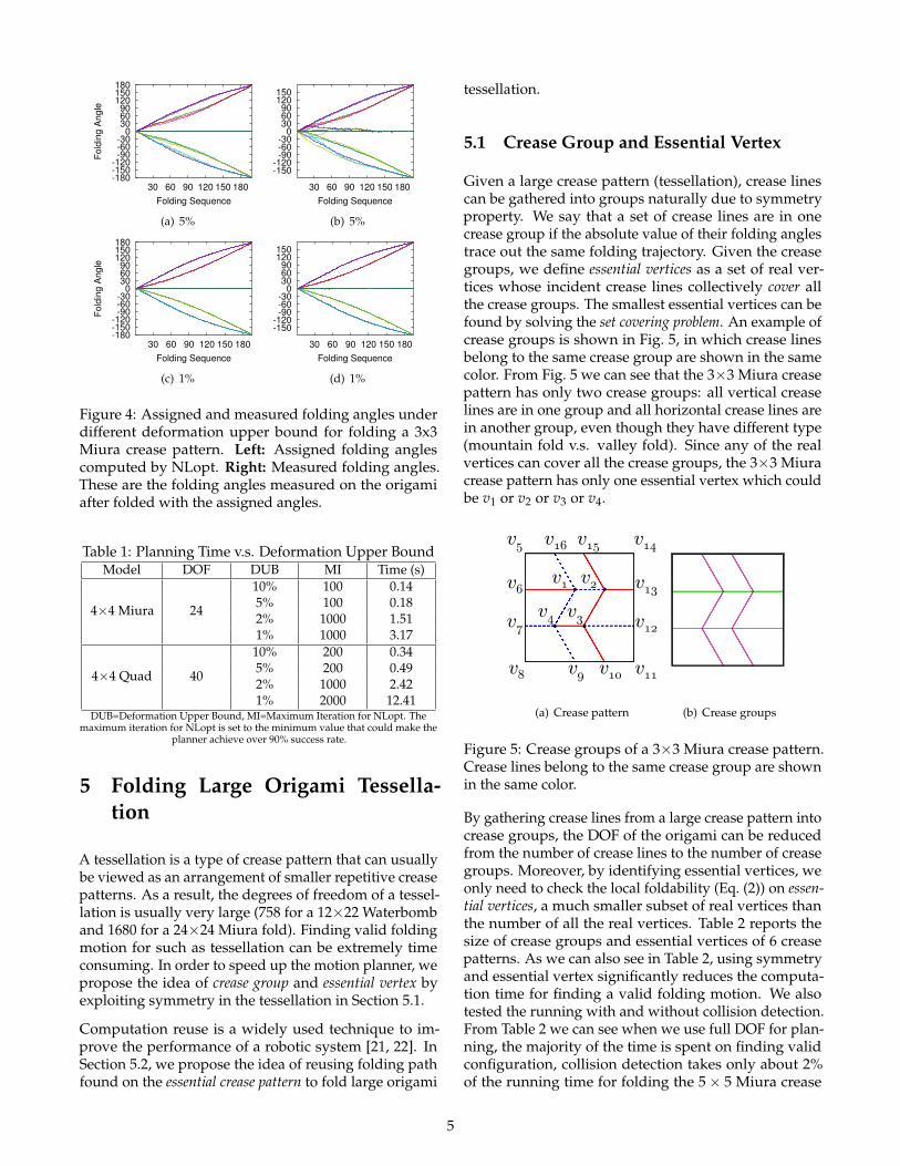
crease pattern with different deformation bounds foundby the proposed method are shown in Fig. 4. We can seethat there are huge differences between assigned foldingangles and measured ones due to deformation. Somevirtual edges have more than 15◦ folding angles whichmeans some panels have been bended in order to re-duce the deformation which is not tolerable in practice.Theoretically, they should be the same if the configu-ration is foldable and the origami will be deformationfree. Within 1% deformation, they become identical (seeFig. 4(d) and Fig. 4(c)). Note that, instead of simply filter-ing out configurations with large deformation, we havealso tried incorporating maximum deformation in theobjective function, but the optimization process is oftentrapped in local minima due to the higher complexity ofthe objective function.
-1
-0.5
0
0.5
1
1.5
30 60 90 120 150 180
Defo
rmation (
%)
Folding Sequence(a) 3×3 Miura
-10-8-6-4-2024
30 60 90 120 150 180
Defo
rmation (
%)
Folding Sequence(b) 5×5 Miura
Figure 3: Edge deformations during the folding processby requiring F(C) < 0.1 for Miura crease patterns. Left:Crease patterns. Right: Edge deformations.
Running times against various deformation upperbounds are shown in Table 1. As we can see, when lowerthe deformation tolerance, our method takes longer timeto find a valid path which is expected. The main com-putation time is from the increase in the number of it-erations needed to find an accurate enough foldableconfiguration in NLopt.
Large Origami Tessellation Though FROCC works wellin lower dimensional space (<10), with the increasing ofthe complexity of the crease pattern (e.g., large origamitessellation), it becomes harder for FROCC to find a validpath. Detailed discussion regarding this issue will begiven in Section 5.
4
-180-150-120-90-60-30
0306090
120150180
30 60 90 120 150 180
Fold
ing A
ngle
Folding Sequence
(a) 5%
-150-120-90-60-30
0306090
120150
30 60 90 120 150 180
Fold
ing A
ngle
Folding Sequence
(b) 5%
-180-150-120-90-60-30
0306090
120150180
30 60 90 120 150 180
Fold
ing A
ngle
Folding Sequence
(c) 1%
-150-120-90-60-30
0306090
120150
30 60 90 120 150 180
Fold
ing A
ngle
Folding Sequence
(d) 1%
Figure 4: Assigned and measured folding angles underdifferent deformation upper bound for folding a 3x3Miura crease pattern. Left: Assigned folding anglescomputed by NLopt. Right: Measured folding angles.These are the folding angles measured on the origamiafter folded with the assigned angles.
Table 1: Planning Time v.s. Deformation Upper BoundModel DOF DUB MI Time (s)
4×4 Miura 24
10% 100 0.145% 100 0.182% 1000 1.511% 1000 3.17
4×4 Quad 40
10% 200 0.345% 200 0.492% 1000 2.421% 2000 12.41
DUB=Deformation Upper Bound, MI=Maximum Iteration for NLopt. Themaximum iteration for NLopt is set to the minimum value that could make the
planner achieve over 90% success rate.
5 Folding Large Origami Tessella-tion
A tessellation is a type of crease pattern that can usuallybe viewed as an arrangement of smaller repetitive creasepatterns. As a result, the degrees of freedom of a tessel-lation is usually very large (758 for a 12×22 Waterbomband 1680 for a 24×24 Miura fold). Finding valid foldingmotion for such as tessellation can be extremely timeconsuming. In order to speed up the motion planner, wepropose the idea of crease group and essential vertex byexploiting symmetry in the tessellation in Section 5.1.
Computation reuse is a widely used technique to im-prove the performance of a robotic system [21, 22]. InSection 5.2, we propose the idea of reusing folding pathfound on the essential crease pattern to fold large origami
tessellation.
5.1 Crease Group and Essential Vertex
Given a large crease pattern (tessellation), crease linescan be gathered into groups naturally due to symmetryproperty. We say that a set of crease lines are in onecrease group if the absolute value of their folding anglestrace out the same folding trajectory. Given the creasegroups, we define essential vertices as a set of real ver-tices whose incident crease lines collectively cover allthe crease groups. The smallest essential vertices can befound by solving the set covering problem. An example ofcrease groups is shown in Fig. 5, in which crease linesbelong to the same crease group are shown in the samecolor. From Fig. 5 we can see that the 3×3 Miura creasepattern has only two crease groups: all vertical creaselines are in one group and all horizontal crease lines arein another group, even though they have different type(mountain fold v.s. valley fold). Since any of the realvertices can cover all the crease groups, the 3×3 Miuracrease pattern has only one essential vertex which couldbe v1 or v2 or v3 or v4.
v1 v2
v3 v4
v5
v6
v7
v8 v9
v10
v11
v12
v13
v14
v15
v16
(a) Crease pattern (b) Crease groups
Figure 5: Crease groups of a 3×3 Miura crease pattern.Crease lines belong to the same crease group are shownin the same color.
By gathering crease lines from a large crease pattern intocrease groups, the DOF of the origami can be reducedfrom the number of crease lines to the number of creasegroups. Moreover, by identifying essential vertices, weonly need to check the local foldability (Eq. (2)) on essen-tial vertices, a much smaller subset of real vertices thanthe number of all the real vertices. Table 2 reports thesize of crease groups and essential vertices of 6 creasepatterns. As we can also see in Table 2, using symmetryand essential vertex significantly reduces the computa-tion time for finding a valid folding motion. We alsotested the running with and without collision detection.From Table 2 we can see when we use full DOF for plan-ning, the majority of the time is spent on finding validconfiguration, collision detection takes only about 2%of the running time for folding the 5× 5 Miura crease
5
pattern. However, when we use symmetry property andessential vertex, the running time reduced significantly,collision detection (with almost the same amount of com-putation) then dominates the running time which takesabout 83% on average.
5.2 Reusing Folding Path
Given a crease pattern (tessellation), if this crease patternis rigid foldable, it is expected that the folding angles ofall crease lines in the same crease group remains identicaleven when planning is done using the full DOF. Furthermore, the trajectories are expected remain identical whenfolding a smaller but same type tessellation as shown inFig. 6.
-150-120
-90-60-30
0306090
120150
30 60 90 120 150 180
Fo
ldin
g A
ng
le
Folding Sequence
(a) 3×3 Miura DOF=12
-150-120
-90-60-30
0306090
120150
30 60 90 120 150 180
Fo
ldin
g A
ng
le
Folding Sequence
(b) 5×5 Miura DOF=40
Figure 6: Folding paths found without using symmetryinformation.
This give us the idea of reusing the folding path foundon smaller crease pattern to fold the large one whichis much more computational efficient. With the creasegroup and essential vertex in mind, here we define theconcept of essential crease pattern which is the smallestcrease pattern that contains all essential vertices as realvertices. We first find a folding path whose deformationis enough low on the essential crease pattern that couldsatisfy the deformation criteria when folding the largerpattern with it since the deformation will be amplifiedwith the increase of size of the crease pattern. Then thefolding path is applied to the original crease pattern.
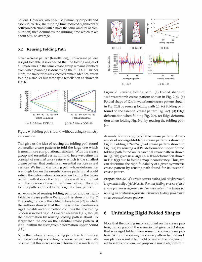
An example of reusing folding path for another rigid-foldable crease pattern Waterbomb is shown in Fig. 7.The configuration of the folded tube is from [23] in whichthe authors showed that the tube is in fact continuousrigid foldable and our method confirms that the foldingprocess is indeed rigid. As we can see from Fig. 7, thoughthe deformation by reusing folding path is about 10xlarger than the one on the essential crease pattern, itis still within the user given deformation upper bound(1%).
Note that, when reusing folding path, the deformationwill be scaled up according to crease pattern size. Weobserve that this increasing in deformation is much more
(a) 4×6 (b) 12×14
-30
0
30
60
90
30 60
Fo
ldin
g A
ng
le
Folding Sequence
(c) 4×6
-0.1-0.08-0.06-0.04-0.02
00.020.040.060.08
30 60
De
form
atio
n (
%)
Folding Sequence
(d) 4×6
-0.8
-0.6
-0.4
-0.2
0
0.2
0.4
30 60
De
form
atio
n (
%)
Folding Sequence
(e) 12×14
Figure 7: Reusing folding path. (a) Folded shape of4×6 waterbomb crease pattern shown in Fig. 2(c). (b)Folded shape of 12×14 waterbomb crease pattern shownin Fig. 2(d) by reusing folding path (c). (c) Folding pathfound on the essential crease pattern Fig. 2(c). (d) Edgedeformation when folding Fig. 2(c). (e) Edge deforma-tion when folding Fig. 2(d) by reusing the folding path(c).
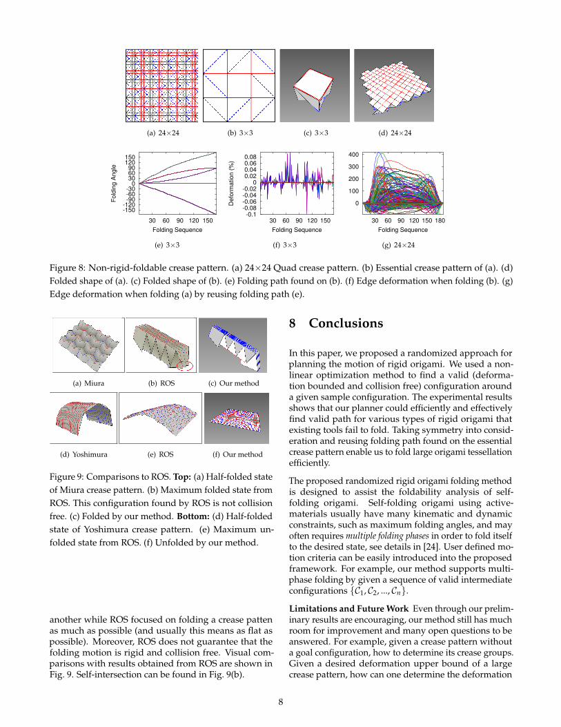
dramatic for non-rigid-foldable crease pattern. An ex-ample of non-rigid-foldable crease pattern is shown inFig. 8. Folding a 24×24 Quad crease pattern shown inFig. 8(a) by reusing a 0.1% deformation upper boundfolding path found on its essential crease pattern shownin Fig. 8(b) gives us a large (> 400%) deformation shownin Fig. 8(g) due to folding map inconsistency. Thus, wecan determine the rigid-foldability of a given symmetriccrease pattern by reusing path found for its essentialcrease pattern.
Proposition 5.1 If a crease pattern with a goal configurationis symmetrically rigid foldable, then the folding process of thatcrease pattern is deformation bounded when it is folded byreusing an arbitrary deformation bounded folding path foundon its essential crease pattern.
6 Unfolding Rigid Folded Shapes
Note that the folding map is applied on the crease pat-tern, thinking about the scenario that given a 3D shapethat was rigid folded from some unknown crease pat-tern. Without knowing the crease pattern beforehand,our planner is not able to fold or unfold the origami. Toaddress this problem, we propose a novel algorithm to
6
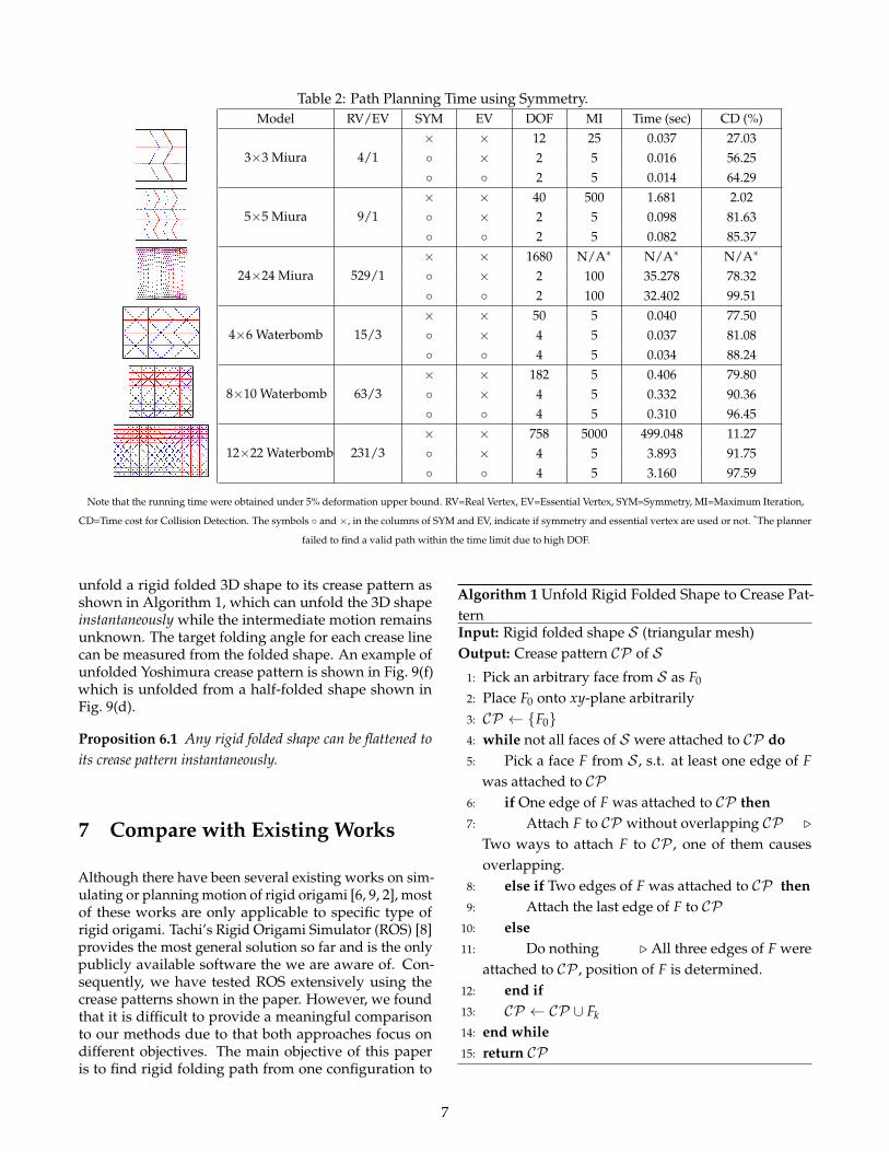
Table 2: Path Planning Time using Symmetry.Model RV/EV SYM EV DOF MI Time (sec) CD (%)
3×3 Miura 4/1× × 12 25 0.037 27.03◦ × 2 5 0.016 56.25◦ ◦ 2 5 0.014 64.29
5×5 Miura 9/1× × 40 500 1.681 2.02◦ × 2 5 0.098 81.63◦ ◦ 2 5 0.082 85.37
24×24 Miura 529/1× × 1680 N/A∗ N/A∗ N/A∗
◦ × 2 100 35.278 78.32◦ ◦ 2 100 32.402 99.51
4×6 Waterbomb 15/3× × 50 5 0.040 77.50◦ × 4 5 0.037 81.08◦ ◦ 4 5 0.034 88.24
8×10 Waterbomb 63/3× × 182 5 0.406 79.80◦ × 4 5 0.332 90.36◦ ◦ 4 5 0.310 96.45
12×22 Waterbomb 231/3× × 758 5000 499.048 11.27◦ × 4 5 3.893 91.75◦ ◦ 4 5 3.160 97.59
Note that the running time were obtained under 5% deformation upper bound. RV=Real Vertex, EV=Essential Vertex, SYM=Symmetry, MI=Maximum Iteration,
CD=Time cost for Collision Detection. The symbols ◦ and ×, in the columns of SYM and EV, indicate if symmetry and essential vertex are used or not. *The planner
failed to find a valid path within the time limit due to high DOF.
unfold a rigid folded 3D shape to its crease pattern asshown in Algorithm 1, which can unfold the 3D shapeinstantaneously while the intermediate motion remainsunknown. The target folding angle for each crease linecan be measured from the folded shape. An example ofunfolded Yoshimura crease pattern is shown in Fig. 9(f)which is unfolded from a half-folded shape shown inFig. 9(d).
Proposition 6.1 Any rigid folded shape can be flattened toits crease pattern instantaneously.
7 Compare with Existing Works
Although there have been several existing works on sim-ulating or planning motion of rigid origami [6, 9, 2], mostof these works are only applicable to specific type ofrigid origami. Tachi’s Rigid Origami Simulator (ROS) [8]provides the most general solution so far and is the onlypublicly available software the we are aware of. Con-sequently, we have tested ROS extensively using thecrease patterns shown in the paper. However, we foundthat it is difficult to provide a meaningful comparisonto our methods due to that both approaches focus ondifferent objectives. The main objective of this paperis to find rigid folding path from one configuration to
Algorithm 1 Unfold Rigid Folded Shape to Crease Pat-ternInput: Rigid folded shape S (triangular mesh)Output: Crease pattern CP of S
1: Pick an arbitrary face from S as F0
2: Place F0 onto xy-plane arbitrarily3: CP ← {F0}4: while not all faces of S were attached to CP do5: Pick a face F from S , s.t. at least one edge of F
was attached to CP6: if One edge of F was attached to CP then7: Attach F to CP without overlapping CP .
Two ways to attach F to CP , one of them causesoverlapping.
8: else if Two edges of F was attached to CP then9: Attach the last edge of F to CP
10: else11: Do nothing . All three edges of F were
attached to CP , position of F is determined.12: end if13: CP ← CP ∪ Fk
14: end while15: return CP
7
(a) 24×24 (b) 3×3 (c) 3×3 (d) 24×24
-150-120
-90-60-30
0306090
120150
30 60 90 120 150
Fo
ldin
g A
ng
le
Folding Sequence
(e) 3×3
-0.1-0.08-0.06-0.04-0.02
00.020.040.060.08
30 60 90 120 150
De
form
atio
n (
%)
Folding Sequence
(f) 3×3
0
100
200
300
400
30 60 90 120 150 180
De
form
atio
n (
%)
Folding Sequence
(g) 24×24
Figure 8: Non-rigid-foldable crease pattern. (a) 24×24 Quad crease pattern. (b) Essential crease pattern of (a). (d)Folded shape of (a). (c) Folded shape of (b). (e) Folding path found on (b). (f) Edge deformation when folding (b). (g)Edge deformation when folding (a) by reusing folding path (e).
(a) Miura (b) ROS (c) Our method
(d) Yoshimura (e) ROS (f) Our method
Figure 9: Comparisons to ROS. Top: (a) Half-folded stateof Miura crease pattern. (b) Maximum folded state fromROS. This configuration found by ROS is not collisionfree. (c) Folded by our method. Bottom: (d) Half-foldedstate of Yoshimura crease pattern. (e) Maximum un-folded state from ROS. (f) Unfolded by our method.
another while ROS focused on folding a crease pattenas much as possible (and usually this means as flat aspossible). Moreover, ROS does not guarantee that thefolding motion is rigid and collision free. Visual com-parisons with results obtained from ROS are shown inFig. 9. Self-intersection can be found in Fig. 9(b).
8 Conclusions
In this paper, we proposed a randomized approach forplanning the motion of rigid origami. We used a non-linear optimization method to find a valid (deforma-tion bounded and collision free) configuration arounda given sample configuration. The experimental resultsshows that our planner could efficiently and effectivelyfind valid path for various types of rigid origami thatexisting tools fail to fold. Taking symmetry into consid-eration and reusing folding path found on the essentialcrease pattern enable us to fold large origami tessellationefficiently.
The proposed randomized rigid origami folding methodis designed to assist the foldability analysis of self-folding origami. Self-folding origami using active-materials usually have many kinematic and dynamicconstraints, such as maximum folding angles, and mayoften requires multiple folding phases in order to fold itselfto the desired state, see details in [24]. User defined mo-tion criteria can be easily introduced into the proposedframework. For example, our method supports multi-phase folding by given a sequence of valid intermediateconfigurations {C1, C2, ..., Cn}.
Limitations and Future Work Even through our prelim-inary results are encouraging, our method still has muchroom for improvement and many open questions to beanswered. For example, given a crease pattern withouta goal configuration, how to determine its crease groups.Given a desired deformation upper bound of a largecrease pattern, how can one determine the deformation
8
upper bound required for its essential crease pattern.
References
[1] S. Felton, M. Tolley, E. Demaine, D. Rus, andR. Wood, “A method for building self-folding ma-chines,” Science, vol. 345, no. 6197, pp. 644–646,2014.
[2] B. An, N. Benbernou, E. D. Demaine, and D. Rus,“Planning to fold multiple objects from a single self-folding sheet,” Robotica, vol. 29, no. 1, pp. 87–102,2011.
[3] L. Swanstrom, M. Whiteford, and Y. Khajanchee,“Developing essential tools to enable transgastricsurgery,” Surgical endoscopy, vol. 22, no. 3, pp. 600–604, 2008.
[4] T. Hull, “On the mathematics of flat origamis,” Con-gressus numerantium, pp. 215–224, 1994.
[5] M. Bern and B. Hayes, “The complexity of flatorigami,” in Proceedings of the seventh annual ACM-SIAM symposium on Discrete algorithms, pp. 175–183,Society for Industrial and Applied Mathematics,1996.
[6] S. Miyazaki, T. Yasuda, S. Yokoi, and J.-i. Tori-waki, “An origami playing simulator in the virtualspace,” Journal of Visualization and Computer Anima-tion, vol. 7, no. 1, pp. 25–42, 1996.
[7] S.-M. Belcastro and T. Hull, “A mathematical modelfor non-flat origami,” in Origami3: Proc. the 3rd In-ternational Meeting of Origami Mathematics, Science,and Education, pp. 39–51, 2002.
[8] T. Tachi, “Simulation of rigid origami,” in Origami4:Proceedings of The Fourth International Conference onOrigami in Science, Mathematics, and Education, 2009.
[9] D. J. Balkcom and M. T. Mason, “Robotic origamifolding,” The International Journal of Robotics Re-search, vol. 27, no. 5, pp. 613–627, 2008.
[10] T. Tachi, “Designing freeform origami tessellationsby generalizing resch’s patterns,” Journal of Mechan-ical Design, vol. 135, no. 11, p. 111006, 2013.
[11] J. H. Yakey, S. M. LaValle, and L. E. Kavraki, “Ran-domized path planning for linkages with closedkinematic chains,” IEEE Transactions on Robotics andAutomation, vol. 17, no. 6, pp. 951–958, 2001.
[12] J. Cortes, T. Simeon, and J. P. Laumond, “A randomloop generator for planning the motions of closedkinematic chains using PRM methods,” in Proc. ofIEEE Int. Conf. on Robotics and Automation, pp. 2141–2146, 2002.
[13] L. Han and N. M. Amato, “A kinematics-basedprobabilistic roadmap method for closed chain sys-tems,” in Robotics:New Directions, (Natick, MA),pp. 233–246, A K Peters, 2000. Book containts theproceedings of the International Workshop on theAlgorithmic Foundations of Robotics (WAFR), Dart-mouth, March 2000.
[14] J. Cortes and T. Simeon, “Sampling-based motionplanning under kinematic loop-closure constraints,”in Proc. Int. Workshop Alg. Found. Robot.(WAFR),2004. To appear.
[15] D. Xie and N. M. Amato, “A kinematics-based prob-abilistic roadmap method for high dof closed chainsystems,” in Robotics and Automation, 2004. Proceed-ings. ICRA’04. 2004 IEEE International Conference on,vol. 1, pp. 473–478, IEEE, 2004.
[16] X. Tang, S. Thomas, P. Coleman, and N. M. Amato,“Reachable distance space: Efficient sampling-basedplanning for spatially constrained systems,” Theinternational journal of robotics research, vol. 29, no. 7,pp. 916–934, 2010.
[17] G. Song and N. M. Amato, “A motion-planningapproach to folding: From paper craft to proteinfolding,” Robotics and Automation, IEEE Transactionson, vol. 20, no. 1, pp. 60–71, 2004.
[18] H. A. Akitaya, J. Mitani, Y. Kanamori, and Y. Fukui,“Generating folding sequences from crease patternsof flat-foldable origami,” in ACM SIGGRAPH 2013Posters, p. 20, ACM, 2013.
[19] Z. Xi and J.-M. Lien, “Folding rigid origami withclosure constraints,” in International Design and En-gineering Technical Conferences & Computers and Infor-mation in Engineering Conference (IDETC/CIE), (Buf-falo, NY), ASME, Aug. 2014.
[20] Z. Xi and J.-M. Lien, “Plan folding motion for rigidorigami via discrete domain sampling,” Tech. Rep.GMU-CS-TR-2015-4, Department of Computer Sci-ence, George Mason University, 4400 UniversityDrive MSN 4A5, Fairfax, VA 22030-4444 USA, 2015.
[21] J.-M. Lien and Y. Lu, “Planning motion in similarenvironments,” in Proceedings of the Robotics: Scienceand Systems Conference (RSS), (Seattle, Washington),Jun 2009.
[22] D. Berenson, P. Abbeel, and K. Goldberg, “A robotpath planning framework that learns from experi-ence,” in Robotics and Automation (ICRA), 2012 IEEEInternational Conference on, pp. 3671–3678, IEEE,2012.
[23] J. Ma and Z. You, “Modelling of the waterbomborigami pattern and its applications,” in Interna-tional Design and Engineering Technical Conferences
9
and Computers and Information in Engineering Confer-ence (IDETC/CIE), (Buffalo, NY), ASME, Aug. 2014.
[24] S. Ahmed, C. Lauff, A. Crivaro, K. McGough,R. Sheridan, M. Frecker, P. von Lockette, Z. Ounaies,T. Simpson, J.-M. Lien, and R. Strzelec, “Multi-fieldresponsive origami structures: Preliminary model-ing and experiments,” in Proceedings of the ASME2013 International Design Engineering Technical Con-ferences & Computers and Information in EngineeringConference, August 2013.
10


![Self-Folding Textiles through Manipulation of Knit Stitch ......origami tessellation patterns [20] (Figure 2). Tessellations are repeated geometric tiling patterns. Using these geometrical](https://static.fdocuments.us/doc/165x107/60b15aa17ff1832b01391d06/self-folding-textiles-through-manipulation-of-knit-stitch-origami-tessellation.jpg)